JP3712413B2 - Improved wound drain system - Google Patents
Improved wound drain systemDownload PDFInfo
- Publication number
- JP3712413B2 JP3712413B2JP51221996AJP51221996AJP3712413B2JP 3712413 B2JP3712413 B2JP 3712413B2JP 51221996 AJP51221996 AJP 51221996AJP 51221996 AJP51221996 AJP 51221996AJP 3712413 B2JP3712413 B2JP 3712413B2
- Authority
- JP
- Japan
- Prior art keywords
- container
- wound
- fluid
- valve means
- passage
- Prior art date
- Legal status (The legal status is an assumption and is not a legal conclusion. Google has not performed a legal analysis and makes no representation as to the accuracy of the status listed.)
- Expired - Lifetime
Links
Images


Classifications
- A—HUMAN NECESSITIES
- A61—MEDICAL OR VETERINARY SCIENCE; HYGIENE
- A61M—DEVICES FOR INTRODUCING MEDIA INTO, OR ONTO, THE BODY; DEVICES FOR TRANSDUCING BODY MEDIA OR FOR TAKING MEDIA FROM THE BODY; DEVICES FOR PRODUCING OR ENDING SLEEP OR STUPOR
- A61M1/00—Suction or pumping devices for medical purposes; Devices for carrying-off, for treatment of, or for carrying-over, body-liquids; Drainage systems
- A61M1/71—Suction drainage systems
- A61M1/74—Suction control
- A61M1/743—Suction control by changing the cross-section of the line, e.g. flow regulating valves
- A—HUMAN NECESSITIES
- A61—MEDICAL OR VETERINARY SCIENCE; HYGIENE
- A61M—DEVICES FOR INTRODUCING MEDIA INTO, OR ONTO, THE BODY; DEVICES FOR TRANSDUCING BODY MEDIA OR FOR TAKING MEDIA FROM THE BODY; DEVICES FOR PRODUCING OR ENDING SLEEP OR STUPOR
- A61M1/00—Suction or pumping devices for medical purposes; Devices for carrying-off, for treatment of, or for carrying-over, body-liquids; Drainage systems
- A61M1/64—Containers with integrated suction means
- A—HUMAN NECESSITIES
- A61—MEDICAL OR VETERINARY SCIENCE; HYGIENE
- A61M—DEVICES FOR INTRODUCING MEDIA INTO, OR ONTO, THE BODY; DEVICES FOR TRANSDUCING BODY MEDIA OR FOR TAKING MEDIA FROM THE BODY; DEVICES FOR PRODUCING OR ENDING SLEEP OR STUPOR
- A61M1/00—Suction or pumping devices for medical purposes; Devices for carrying-off, for treatment of, or for carrying-over, body-liquids; Drainage systems
- A61M1/71—Suction drainage systems
- A61M1/74—Suction control
Landscapes
- Health & Medical Sciences (AREA)
- Heart & Thoracic Surgery (AREA)
- Vascular Medicine (AREA)
- Engineering & Computer Science (AREA)
- Anesthesiology (AREA)
- Biomedical Technology (AREA)
- Hematology (AREA)
- Life Sciences & Earth Sciences (AREA)
- Animal Behavior & Ethology (AREA)
- General Health & Medical Sciences (AREA)
- Public Health (AREA)
- Veterinary Medicine (AREA)
- External Artificial Organs (AREA)
- Cyclones (AREA)
- Centrifugal Separators (AREA)
- Processing Of Stones Or Stones Resemblance Materials (AREA)
Description
Translated fromJapanese技術分野
本発明は、手術後の創傷から分泌液又は体液や膿等の液を抜き取る排液操作(ドレナージ)を助成するために、減圧(大気圧より低い圧力、即ち部分真空)を用いる密閉式創傷ドレンシステムに関する。創傷ドレン法(排液法)の目的は、術後創傷の迅速かつ効率的な治癒を促進することである。
背景技術
創傷、特に、外科手術や事故に基因する創傷から分泌液や膿等の流体を排出(ドレン)するための装置としては、広範囲の装置が提案されている。その一例として、内部ばねの押圧力に抗して、或いは、容器に力を加えて変形させることによって容積を減少させて真空源を創生するようになされたベロータイプの容器がある。
しかしながら、このベロータイプの容器には、幾つかの大きな制約がある。その1つは、所望レベル(度合)の真空を得るために、数ポンド(1b)/平方インチ(in2)(数0.0703Kg/cm2)の程度の真空を創生するのに高い弾性を有する容器としなければならないことである。容器にそのような高い弾性を付与することは、費用効果の高い製造という点からは多少非実用的であり、能率的な排液操作のために望ましい真空レベルを効率的に制御し維持することができない。さらに、低レベルの真空しか創生することができないので、容器に分泌液や膿等(ここでは「流体」と総称する)が満たされるにつれて、容器内の真空が急激に消失する。また、容器内に流体が収集される速度を正確にモニターすることは、不可能ではないにしても、常態では非常に困難である。
創傷流体(創傷から生じる分泌液や膿)を抽出し、収集するための別のタイプの装置として、使い捨ての容器を使用し、そのような容器を電子的に駆動されるポンプに接続するタイプのものがある。このタイプの装置は、精巧な高価なエレクトロニクスと、ポンプと、充電可能なバッテリ又は電源を必要とする。このタイプの装置には必然的に複雑さを伴うので、初期購入価格のみならず、ポンプや制御器のメンテナンス費用をも相当に増大させる。流体容器は使い捨てであるが、ポンプ組立体等の非使い捨て機器や部品を排出された創傷流体による汚染から防護するための特別な手段を講じなければならない。
さらに別のタイプの創傷流体収集器として、所要のレベルの真空を創生するためにペンタンやヘキサン等の揮発性液体を用いる予め排気された容器を使用するタイプの装置がある。しかしながら、このタイプの装置は、真空レベルを変更又は何らかの態様で制御する能力を有しておらず、真空を消散させる漏れを生じた場合、シンクを再設定することができない。従って、このタイプの装置は、多くの状況下において最適な排液を実施するのに理想的な真空度より高い真空度で作動させることが多い。
また、このタイプの創傷流体収集器の変型として、絞り器付き可撓チューブ型の精巧な調節不可の調整器を使用し、そのような別個の調整器をドレンボトルに付設するタイプのものがある。これは、過度に強い吸引力を回避するのに役立つが、依然として、調節不可というう欠点を免れることができず、さらに、調整器は排出された創傷流体によって汚染されるので他の患者に再使用することができないから使い捨て調整器の分だけ相当なコスト高となる。
発明の開示
本発明の目的は、特に費用効果、使い捨て性、信頼性及び操作の容易さの点で改良された密閉式創傷ドレン方法及び装置を提供することである。
本発明は、その一面においては、創傷から流体を抽出する方法であって、創傷と容器の間に通路を設け、これら通路と容器の間に上記通路から上記容器への流体の流れを制御するための弁手段を設け、上記通路内に所定値の、又は所定値より高いレベルの真空を、そして上記容器内に上記通路内の真空より高いレベルの真空を周期的に設定し、上記弁手段を閉鎖している間に創傷から流体を吸引してその流体を上記通路内に収集し、上記通路内の真空レベルが上記所定値より低下するのに応答して上記弁手段を開放して上記通路から上記容器へ流体を排出させ、それによって上記通路内に上記所定値の、又は所定値より高いレベルの真空を再設定することからなる創傷流体抽出方法を提供する。
好ましい実施形態では、容器内に維持する真空レベルを通路内に存在する真空より高くし、弁手段を開放することによって上記通路から上記弁手段を通して上記容器内への流体の流れを設定して上記通路から流体を除去し、それによって上記通路内に所望のレベルの真空を維持する。
通路内に維持すべき真空のレベルは、望ましい所定の範囲内で選択自在とすることが好ましい。
本発明は、その別の面においては、創傷から流体を抽出するための装置であって、創傷から流体を受け取り容器へ送るために一端において創傷に接続するための導管と、使用中これら導管と容器の間に連通を選択的に設定するための弁手段とからなり、この弁手段は、上記導管内の真空のレベルが所定値より低下したときにそれに応答して上記導管と上記容器の間に連通を設定するように構成されている創傷流体抽出装置を提供する。
好ましい実施形態では、上記弁手段は、ゼロから選択された最高度合の真空までの間の真空レベルに応答するように調節自在とし、それによって、導管内の真空レベルを対象とする創傷の状態に適合するように調節することができる構成とする。
上記弁手段は、一方の面において大気圧に露呈され、他方の面において上記導管内に存在する真空レベルに露呈されたダイアフラムによって作動されるようにすることが好ましい。大気圧に対抗してダイアフラムに力を付与するための調節自在の力付与手段を設けることができる。この調節自在の力付与手段によって付与される力と、大気圧によって創生される力との差が、上記弁手段を閉鎖して上記容器と上記導管との間の連通を遮断するために、上記導管内の真空レベルによって与えられる必要のある力、即ち、創傷からの流体の抽出を促進するために上記導管内に存在する真空レベルによって与えられなければならない力である。
かくして、調節自在の力付与手段によって付与される力の度合を変更することによって、創傷から流体を抽出する上記導管内の真空レベルを制御することができる。ダイアフラムに作用する大気圧に対抗して力を付与するための調節自在の力付与手段によって付与される力が大きければ大きいほど、創傷流体を抽出するために上記導管内に維持される大気圧未満の圧力が低くなる。反対に、力付与手段によって付与される力が小さければ小さいほど、創傷流体を抽出するために上記導管内に維持される大気圧未満の圧力が高くなる。
本発明の上記及びその他の目的並びに特徴は、以下に添付図面を参照して述べる本発明の創傷ドレン方法及び装置の実施形態の説明から一層明らかになるであろう。
【図面の簡単な説明】
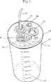
図1は、本発明の創傷ドレン装置の全体構造の透視図である。
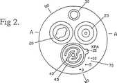
図2は、創傷ドレン装置の上からみた平面図である。
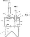
図3は、図2の線3−3に沿ってみた断面図である。
図4は、図2の線3−3に沿ってみた部分断面図である。
図5は、本発明の変型実施形態による創傷ドレン装置の全体構造の透視図である。
図6は、図5に示された調整弁の断面図である。
発明を実施するための最良の形態
図1〜4に示されるように、本発明の創傷ドレン装置は、装置の構成部品が組み込まれたキャップ15付きドレン容器10を有する。それらの構成部品には、創傷ドレンチューブ又は導管22、差し込み継手20、スピゴット(チューブの差し込み部)25、弾性円錐部材30、調整器又は調整弁40等が含まれる。ドレンチューブ22の自由端(図示せず)は、使用中周知の態様で創傷局部につながれる。ドレンチューブ22の他端は、差し込み継手20によって容器10のキャップ15に接続される。ドレンチューブ22の他端には、容器10からチューブ22への流体の逆流を防止する逆止弁35(図3)が装着されている。
容器10内には、逆止弁35から調整弁40の下面に延長したチューブ又は導管50(図4)が設けられている。内部に逆止弁26を備えたスピゴット25は、病院に設置された慣用の真空系統の壁吸引口に接続するための管(図3)を差し込むための継手である。弾性円錐部材30は、容器10内に少くとも部分真空が存在することを可視的に表示するために容器10内へ撓む(へこむ)ダイアフラムとして機能する。
図4を参照して詳しく説明すると、調整弁40は、周縁41においてキャップ15に密封状態に固定された成形エラストマーディスクからなり、該ディスクの上面にはその中心に形成されたねじ付きボス43と、ボス43と同心関係をなす環状の柔軟部分42を有し、下面には、中央弁部分44を有する。調整弁40が自由状態にあるときは、その弁部分44は、スピゴットチューブ又は導管55の上端の弁座63に係合し、チューブ55を閉鎖する。調整弁40の情報には、回転自在の柔軟又は弾性部材45が配置されている。柔軟又は弾性部分45を回転すことによって、外部から調整器40に及ぼされる大気圧に対抗して、調整器40に付与される力を調節することができる。
この柔軟部材45によって付与される力は、その周縁支持部材48に対して該柔軟部材45を回すことによって選択的に調節することができる。その回転度は、調整器40に付与される上向き力を表示する目盛70によって表される。柔軟部材45によって付与される力が大きいほど、ドレンチューブ50内に維持される真空レベルが高くなる。この真空レベルは、ドレン装置のいろいろな異なる用途に応じて異なる柔軟度の柔軟部材45を用いることによってさらに変更することができる。
創傷流体は、ドレンチューブ22及びチューブ50を通して調整弁40の下面にまで吸引された後、スピゴットチューブ55を通して容器10内へ排出される。ドレン容器10は、逆円錐形ベース60を有する。逆円錐形ベース60は、創傷流体の初期流入量をより正確に示すために液面表示器65の垂直目盛の単位を小さくすることを可能にする。ベース60を逆円錐形とすることは、容器10の内部真空による変形抵抗を高くするという点でも有利である。
術後創傷の治癒は創傷局部内からの過剰な流体を適正に排出することによって助成されることは、臨床経験から実証済みである。創傷流体を吸出すために創傷局部に適用すべき理想的な吸引度は、ケース・バイ・ケースで、かつ、治癒過程中においても時に応じて異なるが、一般的には、大気圧よりゼロ乃至15kPa低い範囲(0〜−15kPa)とすることが望ましいということができる。
病院に通常設置されているネットワーク状の壁埋込み真空系統は、大気圧(101.3kPa)より65乃至80kPa低い範囲(−60〜−80kPa)に設定されており、その真空度は、連続的に創傷ドレンを行うのに用いる吸引度としては余りにも強過ぎる。
本発明の創傷ドレン装置によって創傷局部に適用すべき真空レベルは、創傷ドレンチューブ22内の圧力レベルを制御する調整弁40を介して制御することができる。ドレン容器10内の、スピゴットチューブ55が弁座63に連接している地点の圧力は、通常、病院のネットワーク真空系統によって排気された直後では、大気圧より70kPa程度低い値である。この状態では調整弁40は閉鎖しているから、調整弁40に上向き力が加えられるまでは流体の流れは生じない。
真空吸引の助成なしで重力ドレンを行う必要がある場合には、調整弁40に加えられる上向き力をゼロに設定することができる。創傷から新しく流れ出した流体によりドレンチューブ22内の圧力が少しでも上昇すれば、ドレン容器10内の真空度とは関係なく、弁部材44を弁座から引き離すのに十分であり、流体をスピゴットチューブ55を通して容器内へ流入させることができる。
真空吸引の助成が必要とされる場合は、ねじ47によって調整弁40のボス43に固定された柔軟部材45を支持部材48の円形ランプ(傾斜面又はカム面)に圧接させて回転することにより柔軟部材45を撓ませればよい。柔軟部材45の回転によって生じる柔軟部材45の撓みの度合は、回転角度に依存し、校正された目盛70によって読み取ることができる。柔軟部材45の撓みによって調整弁40に加えられる上向き力が、弁部材44の密封を破り、流体をスピゴットチューブ55を通して容器10内へ流入させ、それによって、調整弁40の下側領域内の圧力を低下させ、オリフィス52を通してチューブ50及びドレンチューブ25内の圧力を同様に低下させる。
流体がドレン容器10内へ流入するにつれて、チューブ25及び50内の圧力が低下し続け、柔軟部材45によって調整弁40に加えられる上向き撓み力と、それにに対抗して調整弁40の下面に作用する下向き力とが均衡点に達する。この時点で、調整弁40はその閉鎖位置に戻る。調整弁40の閉鎖位置と開放位置との間の移動行程は僅か1mmの数分の1程度である。
調整弁40が閉鎖されている圧力均衡状態は、柔軟部材45によって調整弁40に加えられる上向き力を変更して、圧力均衡を回復するのに必要とする系内の真空レベルを高くするか、或いは、創傷流体の新しい流れがドレンチューブ25内に流入することによってしか破ることができない。創傷流体の新しい流れの流入によって流体の容積が増大すると、ドレンチューブ25及びチューブ50内の真空レベルを低下させ、従って、調整弁40に作用する下向き力を低下させる。それによって、調整弁40に作用する上向き力と下向き力との均衡が回復されるまでドレン容器10内への創傷流体の流入が可能にされる。
創傷流体がドレン容器10内へ流入するにつれて、容器10内の真空レベルが徐々に低下する。−75kPaにまで排気された容積600ml(ミリリットル)の容器は、400mlの創傷流体を受容すると、真空レベルが−10kPaにまで低下し、450mlの創傷流体を受容すると、真空が完全に消失する。
ドレンチューブ22内の真空レベルの調整度合は、環状の柔軟部分42の中心線から測定した、調整器ディスク40の有効サイズ(面積)と、柔軟部材45によって及ぼされる力に比しての所与の圧力差から得られる力とによって制御される。調整された圧力は、たとえスピゴットチューブ55の断面積が調整器ディスク40の有効面積の2%未満に保たれていたとしても、ドレン容器10内の真空レベルの変化によって影響されることがない。
図5及び6は、調整器即ち調整弁を、創傷流体を収集するドレン容器とは独立して形成した本発明の創傷ドレン装置の変型実施形態を示す。調整弁をドレン容器とは別体とすることによって、ドレン容器を殺菌処理の容易な、従って何度でも再使用可能な簡単な構造とすることができる。これは、図1〜4を参照して上述した、容器と調整弁を一体とした実施形態に比べて大きな商業上の利点である。図1〜4の一体型創傷ドレン装置は、能率的に殺菌することができず、従って、1回の使用で廃棄せざるを得ないからである。
図5に示されるように、この変型実施形態では、容器62は、着脱自在のキャップ又は蓋61を備えた単純な円筒形であり、容器10に関して図3に示されるような逆円錐形のベースを有するものとすることもできる。容器62のキャップ61は、容器62内に収集された流体を廃棄し、次の使用のために殺菌処理をするために着脱自在である。キャップ61に設けられた管継手64は、容器内に所要レベルの真空を初期設定するために病院のネットワーク真空系統に接続することができる。
ドレン容器62とは独立した調整弁65は、移送チューブ又は導管71によって容器62に接続され、創傷には慣用の創傷ドレンチューブ又は導管(一部分が参照番号66で示されている)によって接続される。
図5及び6の実施形態の調整器65の構造及び作動は、先に述べた調整器40と実質的に同じである。調整器ディスク40、柔軟部材45及びねじ47は、それらの作動及び調節態様を含めて、いずれも、図3及び4に関連して説明したのと同じであり、同じ参照番号で示されている。従って、それらの説明はここで繰り返さない。調整器65の、調整器40との相違は、創傷ドレンチューブ66が弁部分44の直ぐ上流のキャビティ52に連通するようにキャビティ69内に密封状態に受容されており、弁部分44の下流の通路55は、移送チューブ71に接続され、創傷流体は、移送チューブ71を介して、容器10と基本的に同じであるが、調整弁を組み込まれていない独立した容器(図6には示されていない)へ移送されるようになされていることである。
別個の調整弁と流体収集容器を用いるこの構成は、容器の殺菌処理が容易かつ完全であるため、容器の再使用を可能にし、創傷ドレンユニット(装置)全体の経済性を高める。
図2〜4又は図5及び6の実施形態の調整弁において、柔軟部材45は、その撓み度合を、従って、調整弁ディスクに及ぼす上向き力を変更するために円形ランプ(傾斜面)に圧接させて回転させるディスクの形とされているが、同様な機能は、下記のような他のいろいろな手段を用いることによって得られる。
(1)一端をキャップに固定し、他端を調整弁ディスクに固定した柔軟な梁部材。この場合、中心ねじ又はランプを用いて梁部材の中心点を持ち上げ、それによって調整弁ディスクに上向き力を付与する。
(2)一端を調整弁ディスクの上面に連結し、他端を調節自在の繋留部材に連結した引張ばね。この場合、引張ばねに可変張力を創生することができ、それによって調整弁ディスクに制御された上向き力を付与する。
本発明の創傷ドレン装置を製造するための素材としては、適当な種類の成形可能なプラスチック材が好ましいが、それに限定されるものではない。例えば、ガラス、金属、ゴム等の他の素材も、費用及び性能に鑑みて、同等に用いることができる。TECHNICAL FIELD The present invention provides reduced pressure (pressure lower than atmospheric pressure, i.e., partial vacuum) in order to assist a drainage operation (drainage) in which secretion fluid or fluid such as body fluid and pus is drained from a wound after surgery. The present invention relates to a closed wound drain system. The purpose of the wound drain method (drainage method) is to promote rapid and efficient healing of the post-operative wound.
BACKGROUND ART A wide range of devices have been proposed as devices for draining fluids such as secretions and pus from wounds, particularly wounds caused by surgery or accidents. As an example, there is a bellows type container that creates a vacuum source by reducing the volume against a pressing force of an internal spring or by applying a force to the container to deform it.
However, this bellows type container has some major limitations. One is high elasticity to create a vacuum of the order of a few pounds (1b) per square inch (in2 ) (several 0.0703 Kg / cm2 ) to obtain the desired level (degree) of vacuum. It must be a container with Giving such a high elasticity to the container is somewhat impractical in terms of cost-effective manufacturing and efficiently controlling and maintaining the desired vacuum level for efficient drainage operations. I can't. Furthermore, since only a low level of vacuum can be created, the vacuum in the container rapidly disappears as the container is filled with secretions, pus, etc. (collectively referred to herein as “fluid”). Also, accurately monitoring the rate at which fluid is collected in the container is usually very difficult, if not impossible.
Another type of device for extracting and collecting wound fluid (secretory fluid and pus resulting from wounds) is a type of using a disposable container and connecting such container to an electronically driven pump There is something. This type of device requires sophisticated and expensive electronics, a pump, and a rechargeable battery or power source. This type of equipment inevitably involves complexity, which considerably increases not only the initial purchase price but also the maintenance costs of the pump and controller. Although the fluid container is disposable, special measures must be taken to protect non-disposable equipment such as pump assemblies and components from contamination by drained wound fluid.
Yet another type of wound fluid collector is a type of device that uses a pre-evacuated container that uses a volatile liquid such as pentane or hexane to create the required level of vacuum. However, this type of device does not have the ability to change or somehow control the vacuum level, and if a leak occurs that dissipates the vacuum, the sink cannot be reset. Therefore, this type of device is often operated at a vacuum level higher than the ideal vacuum level for optimal drainage under many circumstances.
As a variation of this type of wound fluid collector, there is a type in which an elaborate non-adjustable adjuster of a flexible tube type with a restrictor is used, and such a separate adjuster is attached to a drain bottle. . This helps to avoid excessively strong suction forces, but it still cannot escape the disadvantage of non-adjustment, and in addition, the regulator is contaminated by the drained wound fluid and is therefore reconstituted for other patients. Since it cannot be used, the cost is considerably increased by the disposable regulator.
DISCLOSURE OF THE INVENTION An object of the present invention is to provide an improved closed wound drain method and apparatus, particularly in terms of cost effectiveness, disposableness, reliability and ease of operation.
In one aspect, the present invention is a method for extracting fluid from a wound, wherein a passage is provided between the wound and the container, and the flow of fluid from the passage to the container is controlled between the passage and the container. Valve means is provided for periodically setting a vacuum at a predetermined value or higher than a predetermined value in the passage, and setting a vacuum at a level higher than the vacuum in the passage in the container. Fluid is aspirated from the wound and collected in the passage while the valve means is closed, and the valve means is opened in response to the vacuum level in the passage falling below the predetermined value. A method of extracting wound fluid comprising draining fluid from a passageway into the container, thereby resetting a vacuum at the predetermined value or higher than the predetermined value in the passageway.
In a preferred embodiment, the vacuum level maintained in the vessel is higher than the vacuum present in the passage, and the flow of fluid from the passage through the valve means into the vessel is set by opening the valve means. Fluid is removed from the passageway, thereby maintaining a desired level of vacuum in the passageway.
The level of vacuum to be maintained in the passage is preferably selectable within a desired predetermined range.
The invention, in another aspect thereof, is an apparatus for extracting fluid from a wound, the conduit for connecting to the wound at one end for receiving fluid from the wound and delivering it to a container, and these conduits in use. Valve means for selectively setting communication between the containers, the valve means being responsive to a reduction in vacuum level in the conduit between the conduit and the container in response to a drop in the level. A wound fluid extraction device is provided that is configured to establish communication with the device.
In a preferred embodiment, the valve means is adjustable to respond to a vacuum level between zero and a selected maximum degree of vacuum, thereby bringing the vacuum level in the conduit into the state of the wound intended. The configuration can be adjusted to fit.
The valve means is preferably actuated by a diaphragm exposed on one side to atmospheric pressure and on the other side exposed to the vacuum level present in the conduit. Adjustable force applying means for applying force to the diaphragm against the atmospheric pressure can be provided. The difference between the force applied by the adjustable force applying means and the force created by atmospheric pressure closes the valve means and blocks communication between the container and the conduit. The force that needs to be provided by the vacuum level in the conduit, i.e., the force that must be provided by the vacuum level present in the conduit to facilitate the extraction of fluid from the wound.
Thus, by changing the degree of force applied by the adjustable force applying means, the vacuum level in the conduit for extracting fluid from the wound can be controlled. The greater the force applied by the adjustable force applying means for applying force against the atmospheric pressure acting on the diaphragm, the less the atmospheric pressure maintained in the conduit to extract wound fluid The pressure of becomes low. Conversely, the smaller the force applied by the force applying means, the higher the sub-atmospheric pressure maintained in the conduit for extracting wound fluid.
The above and other objects and features of the present invention will become more apparent from the description of the embodiments of the wound drain method and apparatus of the present invention described below with reference to the accompanying drawings.
[Brief description of the drawings]
FIG. 1 is a perspective view of the overall structure of the wound drain device of the present invention.
FIG. 2 is a plan view seen from above the wound drain device.
FIG. 3 is a cross-sectional view taken along line 3-3 in FIG.
FIG. 4 is a partial cross-sectional view taken along line 3-3 in FIG.
FIG. 5 is a perspective view of the overall structure of a wound drain device according to a modified embodiment of the present invention.
6 is a cross-sectional view of the regulating valve shown in FIG.
BEST MODE FORCARRYING OUT THE INVENTION As shown in Figures 1-4, the wound drain device of the present invention has a
In the
Referring to FIG. 4 in detail, the regulating
The force applied by the
The wound fluid is sucked to the lower surface of the regulating
Clinical experience has demonstrated that post-surgical wound healing is aided by properly draining excess fluid from within the wound area. The ideal degree of suction that should be applied to the wound local area to aspirate wound fluid varies case by case and sometimes during the healing process, but is generally zero to less than atmospheric pressure. It can be said that it is desirable to make the
The network-like wall-embedded vacuum system usually installed in hospitals is set in a range (−60 to −80 kPa) lower than atmospheric pressure (101.3 kPa) by 65 to 80 kPa, and the degree of vacuum is continuously The degree of suction used to perform wound draining is too strong.
The vacuum level to be applied to the wound site by the wound drain device of the present invention can be controlled via a regulating
When it is necessary to perform gravity drain without subsidizing vacuum suction, the upward force applied to the regulating
When assistance of vacuum suction is required, the
As the fluid flows into the
A pressure equilibrium condition in which the
As the wound fluid flows into the
The degree of adjustment of the vacuum level in the
Figures 5 and 6 show a modified embodiment of the wound drain device of the present invention in which the regulator or regulating valve is formed independently of the drain container collecting the wound fluid. By making the regulating valve separate from the drain container, the drain container can have a simple structure that can be easily sterilized and can be reused any number of times. This is a significant commercial advantage over the embodiment in which the container and the regulating valve are integrated as described above with reference to FIGS. The integrated wound drain device of FIGS. 1-4 cannot be sterilized efficiently and therefore must be discarded after a single use.
As shown in FIG. 5, in this variant embodiment, the
A regulating
The structure and operation of the
This configuration, which uses a separate regulator valve and fluid collection container, allows the container to be reused because the container is easily and completely sterilized, increasing the overall economics of the wound drain unit.
In the regulating valve of the embodiment of FIGS. 2-4 or 5 and 6, the
(1) A flexible beam member having one end fixed to a cap and the other end fixed to a regulating valve disk. In this case, a center screw or ramp is used to lift the center point of the beam member, thereby applying an upward force to the regulating valve disk.
(2) A tension spring having one end connected to the upper surface of the adjusting valve disk and the other end connected to an adjustable anchoring member. In this case, a variable tension can be created in the tension spring, thereby applying a controlled upward force to the regulating valve disk.
The material for producing the wound drain device of the present invention is preferably an appropriate type of moldable plastic material, but is not limited thereto. For example, other materials such as glass, metal, and rubber can be equally used in view of cost and performance.
Claims (9)
Translated fromJapanese前記弁手段は、前記通路によって抽出された創傷からの流体が、前記弁手段を介して前記容器に流れるように配置され、
使用時には、前記弁手段は、
前記通路内に創傷からの流体が存在することで前記通路内の真空レベルが所定値以下になると、創傷からの流体が前記弁手段を介して前記容器に抽出されるように、外部から加わる大気圧に逆らって開口し、
創傷からの流体を前記弁手段を介して前記容器に抽出した後に、前記通路内の真空レベルが前記所定値以上になると、外部から加わる大気圧の力によって閉鎖するように構成されていること
を特徴とする創傷流体抽出装置。A passage connectable at one end to the patient body, a container for collecting fluid exiting the wound of the patient body through the passage, and fluid from the wound to the container by selectively opening and closing between the passage and the container A device for extracting fluid from a wound in a patient body comprising valve means for controlling the flow of
The valve means is arranged such that fluid from the wound extracted by the passage flows to the container via the valve means;
In use, the valve means is
When fluid from the wound is present in the passage and the vacuum level in the passage becomes a predetermined value or less, a large amount of fluid is applied from the outside so that fluid from the wound is extracted to the container through the valve means. Open against the atmospheric pressure,
After the fluid from the wound is extracted to the container through the valve means, when the vacuum level in the passage becomes equal to or higher than the predetermined value, it is configured to be closed by the force of atmospheric pressure applied from the outside. Wound fluid extraction device characterized.
を特徴とする請求の範囲第1項に記載の創傷流体抽出装置。The valve means includes a disk made of an elastomer material having a flexible annular portion, a valve member that engages with a valve seat, and a flexible member that is flexible or elastic and can be rotated. It is configured to rotate while being brought into pressure contact with the inclination of an annular circular lamp, and to adjust the operation of the valve means against the atmospheric pressure applied from the outside by changing the degree of bending generated in the valve means. The wound fluid extraction device according to claim 1.
を特徴とする請求の範囲第1或いは第2項に記載の創傷流体抽出装置。The wound fluid extraction device according to claim 1 or 2, wherein the container is configured to be detachably connectable to a suction source for evacuating the container.
を特徴とする請求の範囲第3項に記載の創傷流体抽出装置。The wound fluid extraction device according to claim 3, wherein the container includes a check valve for maintaining a vacuum state in the container when the container is disconnected from the suction source.
を特徴とする請求の範囲第1項から第4項のいずれかに記載の創傷流体抽出装置。The wound fluid extraction device according to any one of claims 1 to 4, wherein the valve means can be detachably connected to the container.
を特徴とする請求の範囲第1項から第5項のいずれかに記載の創傷流体抽出装置。The wound fluid extraction device according to any one of claims 1 to 5, wherein the valve means can be detachably connected to the container via a transfer passage.
を特徴とする請求の範囲第4項記載の創傷流体抽出装置。The wound fluid extraction device according to claim 4, wherein the passage, the valve means, and the transfer passage can be detachably connected to the container as an integral assembly.
を特徴とする請求の範囲第1項から第7項のいずれかに記載の創傷流体抽出装置。8. The check valve according to claim 1, wherein a check valve is provided downstream of the valve means to prevent the contained fluid from flowing out of the container into the passage. The wound fluid extraction device as described.
を特徴とする請求の範囲第1項から第8項のいずれかに記載の創傷流体抽出装置。The wound fluid extraction device according to any one of claims 1 to 8, wherein a vacuum level in the passage can be adjusted within a specific range by adjusting the valve means.
Applications Claiming Priority (5)
| Application Number | Priority Date | Filing Date | Title |
|---|---|---|---|
| AUPM8712AAUPM871294A0 (en) | 1994-10-11 | 1994-10-11 | Vacuum assisted wound drainage device |
| AU8712 | 1995-01-04 | ||
| AU0386 | 1995-01-04 | ||
| AUPN0386AAUPN038695A0 (en) | 1995-01-04 | 1995-01-04 | Improved wound drainage system |
| PCT/AU1995/000674WO1996011031A1 (en) | 1994-10-11 | 1995-10-11 | Improved wound drainage system |
Publications (2)
| Publication Number | Publication Date |
|---|---|
| JPH10506816A JPH10506816A (en) | 1998-07-07 |
| JP3712413B2true JP3712413B2 (en) | 2005-11-02 |
Family
ID=25644788
Family Applications (1)
| Application Number | Title | Priority Date | Filing Date |
|---|---|---|---|
| JP51221996AExpired - LifetimeJP3712413B2 (en) | 1994-10-11 | 1995-10-11 | Improved wound drain system |
Country Status (7)
| Country | Link |
|---|---|
| US (1) | US5944703A (en) |
| JP (1) | JP3712413B2 (en) |
| CN (1) | CN1160359A (en) |
| AU (1) | AU695982B2 (en) |
| DE (1) | DE69529165T2 (en) |
| NZ (1) | NZ293884A (en) |
| WO (1) | WO1996011031A1 (en) |
Cited By (1)
| Publication number | Priority date | Publication date | Assignee | Title |
|---|---|---|---|---|
| JP2013508074A (en)* | 2009-10-20 | 2013-03-07 | ケーシーアイ ライセンシング インコーポレイテッド | Dressing decompression indicator, system and method |
Families Citing this family (97)
| Publication number | Priority date | Publication date | Assignee | Title |
|---|---|---|---|---|
| US6183453B1 (en)* | 1997-11-20 | 2001-02-06 | Sherwood Services, Ag | Blood evacuation container with blood spike nesting feature |
| US6022369A (en)* | 1998-02-13 | 2000-02-08 | Precision Vascular Systems, Inc. | Wire device with detachable end |
| SE512807C2 (en)* | 1998-09-02 | 2000-05-15 | Bjoern Flodin | Device for supplying inhalation gas to and removing exhalation gas from a patient |
| GB9822341D0 (en)* | 1998-10-13 | 1998-12-09 | Kci Medical Ltd | Negative pressure therapy using wall suction |
| CA2361648C (en) | 1999-03-09 | 2009-02-17 | Sherwood Services Ag | Medical drainage device with flow restriction feature |
| DE10059710A1 (en)* | 2000-12-01 | 2002-06-06 | Nueesch Engineering Remetschwi | Breast milk pump arrangement as well as control device, distribution valve and pump therefor |
| CA2432755A1 (en) | 2000-12-19 | 2002-06-27 | Hill-Rom Services, Inc. | Low exposure waste disposal suction system |
| IL158708A0 (en)* | 2001-05-02 | 2004-05-12 | Axiom Medical Inc | Transcutaneous fluid drain kit |
| US20030069551A1 (en)* | 2001-10-05 | 2003-04-10 | Axiom Medical, Inc. | Multipurpose drain |
| US6648862B2 (en) | 2001-11-20 | 2003-11-18 | Spheric Products, Ltd. | Personally portable vacuum desiccator |
| EP1449547B1 (en)* | 2001-11-29 | 2012-11-28 | Sumitomo Bakelite Co., Ltd. | Discharging implement for medical care |
| US7846141B2 (en) | 2002-09-03 | 2010-12-07 | Bluesky Medical Group Incorporated | Reduced pressure treatment system |
| GB0224986D0 (en) | 2002-10-28 | 2002-12-04 | Smith & Nephew | Apparatus |
| JP4324438B2 (en)* | 2003-09-30 | 2009-09-02 | ユニ・チャーム株式会社 | Automatic urination treatment device |
| GB0325129D0 (en) | 2003-10-28 | 2003-12-03 | Smith & Nephew | Apparatus in situ |
| US8636721B2 (en) | 2003-11-20 | 2014-01-28 | Henry M. Jackson Foundation For The Advancement Of Military Medicine, Inc. | Portable hand pump for evacuation of fluids |
| US8062272B2 (en) | 2004-05-21 | 2011-11-22 | Bluesky Medical Group Incorporated | Flexible reduced pressure treatment appliance |
| US10058642B2 (en) | 2004-04-05 | 2018-08-28 | Bluesky Medical Group Incorporated | Reduced pressure treatment system |
| US7909805B2 (en) | 2004-04-05 | 2011-03-22 | Bluesky Medical Group Incorporated | Flexible reduced pressure treatment appliance |
| US7790945B1 (en) | 2004-04-05 | 2010-09-07 | Kci Licensing, Inc. | Wound dressing with absorption and suction capabilities |
| GB0508531D0 (en)* | 2005-04-27 | 2005-06-01 | Smith & Nephew | Sai with ultrasound |
| USD539417S1 (en)* | 2004-05-14 | 2007-03-27 | Sound Surgical Technologies Llc | Aspiration canister |
| US8337475B2 (en) | 2004-10-12 | 2012-12-25 | C. R. Bard, Inc. | Corporeal drainage system |
| CA2949821C (en) | 2005-09-06 | 2021-05-18 | Smith & Nephew, Inc. | Self contained wound dressing with micropump |
| JP5237257B2 (en)* | 2006-03-20 | 2013-07-17 | アルコン,インコーポレイティド | Surgical cassette with bubble separation structure |
| US8025650B2 (en) | 2006-06-12 | 2011-09-27 | Wound Care Technologies, Inc. | Negative pressure wound treatment device, and methods |
| US8025173B2 (en) | 2006-09-07 | 2011-09-27 | Allegiance Corporation | Collapsible canister liner for medical fluid collection |
| AU2007311028B2 (en)* | 2006-10-17 | 2013-06-27 | Smith & Nephew Plc | Auxiliary powered negative pressure wound therapy apparatuses and methods |
| US9889239B2 (en) | 2007-03-23 | 2018-02-13 | Allegiance Corporation | Fluid collection and disposal system and related methods |
| AU2008232360A1 (en) | 2007-03-23 | 2008-10-02 | Allegiance Corporation | Fluid collection and disposal system having internchangeable collection and other features and methods relating thereof |
| DE202007009414U1 (en)* | 2007-07-04 | 2008-11-13 | pfm Produkte für die Medizin AG | Pre-evacuated or pre-evacuated container for medical purposes |
| US8021347B2 (en) | 2008-07-21 | 2011-09-20 | Tyco Healthcare Group Lp | Thin film wound dressing |
| US8298200B2 (en) | 2009-06-01 | 2012-10-30 | Tyco Healthcare Group Lp | System for providing continual drainage in negative pressure wound therapy |
| US8152785B2 (en)* | 2008-03-13 | 2012-04-10 | Tyco Healthcare Group Lp | Vacuum port for vacuum wound therapy |
| US20090240218A1 (en)* | 2008-03-20 | 2009-09-24 | Tyco Healthcare Group Lp | Wound Therapy System |
| CN102014982B (en)* | 2008-05-02 | 2014-03-26 | 凯希特许有限公司 | Manually actuated reduced pressure therapy pump with adjustable pressure capability |
| US20090281526A1 (en)* | 2008-05-09 | 2009-11-12 | Tyco Healthcare Group Lp | Negative Pressure Wound Therapy Apparatus Including a Fluid Line Coupling |
| US8177763B2 (en) | 2008-09-05 | 2012-05-15 | Tyco Healthcare Group Lp | Canister membrane for wound therapy system |
| US8414519B2 (en)* | 2008-05-21 | 2013-04-09 | Covidien Lp | Wound therapy system with portable container apparatus |
| US8007481B2 (en) | 2008-07-17 | 2011-08-30 | Tyco Healthcare Group Lp | Subatmospheric pressure mechanism for wound therapy system |
| US10912869B2 (en) | 2008-05-21 | 2021-02-09 | Smith & Nephew, Inc. | Wound therapy system with related methods therefor |
| US8048046B2 (en)* | 2008-05-21 | 2011-11-01 | Tyco Healthcare Group Lp | Wound therapy system with housing and canister support |
| US8257326B2 (en) | 2008-06-30 | 2012-09-04 | Tyco Healthcare Group Lp | Apparatus for enhancing wound healing |
| WO2010005709A1 (en) | 2008-07-08 | 2010-01-14 | Tyco Healthcare Group Lp | Portable negative pressure wound therapy device |
| ES2658263T3 (en) | 2008-08-08 | 2018-03-09 | Smith & Nephew, Inc. | Continuous fiber wound dressing |
| US8251979B2 (en) | 2009-05-11 | 2012-08-28 | Tyco Healthcare Group Lp | Orientation independent canister for a negative pressure wound therapy device |
| US8216198B2 (en) | 2009-01-09 | 2012-07-10 | Tyco Healthcare Group Lp | Canister for receiving wound exudate in a negative pressure therapy system |
| US8827983B2 (en) | 2008-08-21 | 2014-09-09 | Smith & Nephew, Inc. | Sensor with electrical contact protection for use in fluid collection canister and negative pressure wound therapy systems including same |
| US9414968B2 (en) | 2008-09-05 | 2016-08-16 | Smith & Nephew, Inc. | Three-dimensional porous film contact layer with improved wound healing |
| GB0900423D0 (en) | 2009-01-12 | 2009-02-11 | Smith & Nephew | Negative pressure device |
| US8162907B2 (en) | 2009-01-20 | 2012-04-24 | Tyco Healthcare Group Lp | Method and apparatus for bridging from a dressing in negative pressure wound therapy |
| US8246591B2 (en)* | 2009-01-23 | 2012-08-21 | Tyco Healthcare Group Lp | Flanged connector for wound therapy |
| US20100191196A1 (en)* | 2009-01-26 | 2010-07-29 | Heagle David G | Fibrous Wound Filler Material for Negative Pressure Wound Therapy |
| US8167869B2 (en)* | 2009-02-10 | 2012-05-01 | Tyco Healthcare Group Lp | Wound therapy system with proportional valve mechanism |
| US8882678B2 (en) | 2009-03-13 | 2014-11-11 | Atrium Medical Corporation | Pleural drainage system and method of use |
| US20110196321A1 (en) | 2009-06-10 | 2011-08-11 | Tyco Healthcare Group Lp | Fluid Collection Canister Including Canister Top with Filter Membrane and Negative Pressure Wound Therapy Systems Including Same |
| US20100324516A1 (en) | 2009-06-18 | 2010-12-23 | Tyco Healthcare Group Lp | Apparatus for Vacuum Bridging and/or Exudate Collection |
| WO2011008961A1 (en) | 2009-07-15 | 2011-01-20 | Allegiance Corporation | Fluid collection and disposal system and related methods |
| US20110139667A1 (en)* | 2009-12-11 | 2011-06-16 | Burgess James E | Stackable Suction Canister and Lid Assembly |
| USD641866S1 (en)* | 2010-04-29 | 2011-07-19 | Medline Industries, Inc. | Fluid collection container with lid |
| USD644323S1 (en)* | 2010-04-29 | 2011-08-30 | Medline Industries, Inc. | Fluid collection container lid |
| USD679807S1 (en) | 2010-04-29 | 2013-04-09 | Medline Industries, Inc. | Fluid collection container lid |
| JP5844359B2 (en)* | 2010-06-29 | 2016-01-13 | リサーチ メディカル プロプライエタリー リミテッドResearch Medical Pty Ltd | Wound drainage control device |
| GB201011173D0 (en) | 2010-07-02 | 2010-08-18 | Smith & Nephew | Provision of wound filler |
| ES2639776T3 (en) | 2010-09-20 | 2017-10-30 | Smith & Nephew, Plc | Negative pressure device |
| GB201020005D0 (en) | 2010-11-25 | 2011-01-12 | Smith & Nephew | Composition 1-1 |
| CA2819032C (en) | 2010-11-25 | 2020-06-23 | Smith & Nephew Plc | Composition i-ii and products and uses thereof |
| USD683466S1 (en)* | 2011-01-19 | 2013-05-28 | Mallinckrodt Llc | Radiation shielding container lid |
| US9050175B2 (en) | 2011-01-20 | 2015-06-09 | Scott Stephan | Therapeutic treatment pad |
| US20120192977A1 (en)* | 2011-01-27 | 2012-08-02 | Tsao Yu-Yao | Duck-billed check valve |
| US9302034B2 (en) | 2011-04-04 | 2016-04-05 | Smith & Nephew, Inc. | Negative pressure wound therapy dressing |
| RU2611760C2 (en) | 2011-06-07 | 2017-02-28 | Смит Энд Нефью Плс | Wound contacting elements and methods of their use |
| USD694404S1 (en) | 2011-06-09 | 2013-11-26 | Medline Industries, Inc. | Fluid collection container lid |
| DE102011052196B4 (en)* | 2011-07-27 | 2017-06-08 | MAQUET GmbH | Device for aspirating liquids and / or particles from body orifices |
| DE102011114266A1 (en)* | 2011-09-23 | 2013-03-28 | Michael Yim | Wound water suction system has wound pad that is connected with vacuum source such as single-use redon bottle via hose system for wound water suction |
| US20150159066A1 (en) | 2011-11-25 | 2015-06-11 | Smith & Nephew Plc | Composition, apparatus, kit and method and uses thereof |
| CN103316383B (en)* | 2012-03-19 | 2015-06-17 | 北京万生人和科技有限公司 | Vacuum extractor |
| AU2013201891B2 (en)* | 2012-03-26 | 2017-10-12 | Datamars Limited | Applicator |
| ES2820373T3 (en)* | 2012-09-14 | 2021-04-20 | 3M Innovative Properties Co | System to regulate pressure |
| US8920394B2 (en) | 2012-12-19 | 2014-12-30 | Dornoch Medical Systems, Inc. | Suction canister liner and system |
| EP2968647B1 (en) | 2013-03-15 | 2022-06-29 | Smith & Nephew plc | Wound dressing sealant and use thereof |
| US20160120706A1 (en) | 2013-03-15 | 2016-05-05 | Smith & Nephew Plc | Wound dressing sealant and use thereof |
| US9474837B2 (en) | 2013-07-03 | 2016-10-25 | Dornoch Medical Systems, Inc. | Fluid level sensor cover for a medical waste fluid collection and disposal system |
| JP6560201B2 (en)* | 2013-07-10 | 2019-08-14 | ケーシーアイ ライセンシング インコーポレイテッド | Manually regulated negative pressure pump with adapter for external pressure source |
| CA3179001A1 (en) | 2014-07-31 | 2016-02-04 | Smith & Nephew, Inc. | Systems and methods for applying reduced pressure therapy |
| US12133789B2 (en) | 2014-07-31 | 2024-11-05 | Smith & Nephew, Inc. | Reduced pressure therapy apparatus construction and control |
| CA2908983A1 (en) | 2014-10-20 | 2016-04-20 | Amico Patient Care Corporation | Method and system for signaling responsive to sensing contamination in a suction regulator device |
| US10888642B2 (en) | 2014-10-20 | 2021-01-12 | Amico Patient Care Corporation | Method and system for signaling responsive to sensing contamination in a suction regulator device |
| US10596305B2 (en) | 2016-01-25 | 2020-03-24 | Medline Industries, Inc. | Suction canister and corresponding systems and methods |
| US10398807B2 (en) | 2016-01-25 | 2019-09-03 | Medline Industries, Inc. | Canister lid and corresponding systems and methods |
| US10688226B2 (en) | 2016-01-25 | 2020-06-23 | Medline Industries, Inc. | Canister lid and corresponding systems and methods |
| US11141513B2 (en) | 2016-01-28 | 2021-10-12 | Kci Licensing, Inc. | Fluid container with pressure regulation |
| WO2018017365A1 (en) | 2016-07-18 | 2018-01-25 | Merit Medical Systems, Inc. | Inflatable radial artery compression device |
| TWI620923B (en)* | 2016-10-19 | 2018-04-11 | 邦睿生技股份有限公司 | Collection bottle and method for checking characteristic of sample |
| US11439797B2 (en)* | 2017-02-10 | 2022-09-13 | Medtronic Advanced Energy Llc. | Surgical drain system and container |
| EP3873551B1 (en)* | 2018-11-02 | 2025-10-15 | Solventum Intellectual Properties Company | Wound therapy tubeset system for wound volume estimation |
| US12426864B2 (en) | 2021-06-18 | 2025-09-30 | Merit Medical Systems, Inc. | Hemostasis devices and methods of use |
Family Cites Families (13)
| Publication number | Priority date | Publication date | Assignee | Title |
|---|---|---|---|---|
| US3086528A (en)* | 1959-01-26 | 1963-04-23 | Chemetron Corp | Intermittent vacuum regulator |
| US3659605A (en)* | 1970-04-08 | 1972-05-02 | Airco Inc | Pneumatic suction system |
| US3830238A (en)* | 1972-11-07 | 1974-08-20 | Deknatel Inc | Surgical drainage system with pressure measuring device |
| US4303072A (en)* | 1977-12-15 | 1981-12-01 | Robertshaw Controls Company | Intermittent patient suction system and control means therefor |
| US4372336A (en)* | 1980-06-17 | 1983-02-08 | Sherwood Medical Industries, Inc. | Chest drainage unit |
| US4681571A (en)* | 1981-04-23 | 1987-07-21 | C. R. Bard, Inc. | Suction canister with disposable liner and check valve |
| AU563105B2 (en)* | 1982-10-15 | 1987-06-25 | Sorenson Research Co. Inc. | Suction drainage apparatus |
| US4654029A (en)* | 1982-12-13 | 1987-03-31 | Howmedica, Inc. | Electronic drainage system |
| FR2560770A1 (en)* | 1984-03-09 | 1985-09-13 | Cheval Marguerite | Mini vacuum reducer adjusted to a fixed value for medical use |
| US4718895A (en)* | 1986-01-24 | 1988-01-12 | Bioresearch Inc. | Suction regulator |
| IN169588B (en)* | 1986-10-07 | 1991-11-16 | Pfizer Hospital Prod | |
| EP0494089B1 (en)* | 1987-01-20 | 1998-07-08 | Medinorm Aktiengesellschaft Medizintechnische Produkte | Connection device for wound suction bottle |
| US5423780A (en)* | 1994-09-09 | 1995-06-13 | Malette; William G. | Thorax drainage apparatus with variable vacuum control |
- 1995
- 1995-10-11JPJP51221996Apatent/JP3712413B2/ennot_activeExpired - Lifetime
- 1995-10-11AUAU36448/95Apatent/AU695982B2/ennot_activeExpired
- 1995-10-11WOPCT/AU1995/000674patent/WO1996011031A1/ennot_activeApplication Discontinuation
- 1995-10-11CNCN95195623Apatent/CN1160359A/enactivePending
- 1995-10-11USUS08/817,497patent/US5944703A/ennot_activeExpired - Lifetime
- 1995-10-11DEDE69529165Tpatent/DE69529165T2/ennot_activeExpired - Lifetime
- 1995-10-11NZNZ293884Apatent/NZ293884A/ennot_activeIP Right Cessation
Cited By (2)
| Publication number | Priority date | Publication date | Assignee | Title |
|---|---|---|---|---|
| JP2013508074A (en)* | 2009-10-20 | 2013-03-07 | ケーシーアイ ライセンシング インコーポレイテッド | Dressing decompression indicator, system and method |
| JP2015006376A (en)* | 2009-10-20 | 2015-01-15 | ケーシーアイ ライセンシング インコーポレイテッド | Dressing decompression indicator, system and method |
Also Published As
| Publication number | Publication date |
|---|---|
| US5944703A (en) | 1999-08-31 |
| NZ293884A (en) | 1998-09-24 |
| JPH10506816A (en) | 1998-07-07 |
| WO1996011031A1 (en) | 1996-04-18 |
| CN1160359A (en) | 1997-09-24 |
| AU695982B2 (en) | 1998-08-27 |
| DE69529165T2 (en) | 2003-10-02 |
| DE69529165D1 (en) | 2003-01-23 |
| AU3644895A (en) | 1996-05-02 |
Similar Documents
| Publication | Publication Date | Title |
|---|---|---|
| JP3712413B2 (en) | Improved wound drain system | |
| US5073172A (en) | Device for aspirating wound fluids | |
| AU2017345416B2 (en) | Electronic vacuum regulator device | |
| US5730730A (en) | Liquid flow rate control device | |
| US6213986B1 (en) | Liquid flow rate control device | |
| US3507395A (en) | Cardiotomy reservoir | |
| US4306557A (en) | Vacuum urological surgical irrigating solution collecting system | |
| US5392653A (en) | Pressure transducer magnetically-coupled interface complementing minimal diaphragm movement during operation | |
| US5910110A (en) | Controlling pressure in the eye during surgery | |
| US8157792B2 (en) | Wound drainage suction relief | |
| US4681571A (en) | Suction canister with disposable liner and check valve | |
| US7815616B2 (en) | Device for treating a wound | |
| JPH11514271A (en) | Wound drainage system | |
| EP0482096A1 (en) | Irrigation dressing | |
| US11478751B2 (en) | Automated single-use filtering apparatus, and method for controlling an automated single-use filtering apparatus | |
| JPH05509022A (en) | Blood extraction and reinfusion flow control system and method | |
| JP5844359B2 (en) | Wound drainage control device | |
| WO2000076563A1 (en) | Intermittent regulator | |
| EP0783339B1 (en) | Improved wound drainage apparatus | |
| US5993657A (en) | Adjustable collection canister for continuous renal replacement therapy | |
| US2939460A (en) | Intermittent surgical suction apparatus | |
| RU2001104097A (en) | ASPIRATION AND IRRIGATION APPARATUS FOR OPHTHALMIC SURGERY | |
| EP0862470A1 (en) | Liquid flow rate control device | |
| RU70132U1 (en) | VACUUM ASpirator | |
| GB2418617A (en) | Bladder regulating mechanism |
Legal Events
| Date | Code | Title | Description |
|---|---|---|---|
| A131 | Notification of reasons for refusal | Free format text:JAPANESE INTERMEDIATE CODE: A131 Effective date:20050208 | |
| A521 | Request for written amendment filed | Free format text:JAPANESE INTERMEDIATE CODE: A523 Effective date:20050506 | |
| TRDD | Decision of grant or rejection written | ||
| A01 | Written decision to grant a patent or to grant a registration (utility model) | Free format text:JAPANESE INTERMEDIATE CODE: A01 Effective date:20050726 | |
| A61 | First payment of annual fees (during grant procedure) | Free format text:JAPANESE INTERMEDIATE CODE: A61 Effective date:20050817 | |
| R150 | Certificate of patent or registration of utility model | Free format text:JAPANESE INTERMEDIATE CODE: R150 | |
| FPAY | Renewal fee payment (event date is renewal date of database) | Free format text:PAYMENT UNTIL: 20080826 Year of fee payment:3 | |
| FPAY | Renewal fee payment (event date is renewal date of database) | Free format text:PAYMENT UNTIL: 20090826 Year of fee payment:4 | |
| FPAY | Renewal fee payment (event date is renewal date of database) | Free format text:PAYMENT UNTIL: 20090826 Year of fee payment:4 | |
| FPAY | Renewal fee payment (event date is renewal date of database) | Free format text:PAYMENT UNTIL: 20100826 Year of fee payment:5 | |
| FPAY | Renewal fee payment (event date is renewal date of database) | Free format text:PAYMENT UNTIL: 20100826 Year of fee payment:5 | |
| FPAY | Renewal fee payment (event date is renewal date of database) | Free format text:PAYMENT UNTIL: 20110826 Year of fee payment:6 | |
| FPAY | Renewal fee payment (event date is renewal date of database) | Free format text:PAYMENT UNTIL: 20120826 Year of fee payment:7 | |
| FPAY | Renewal fee payment (event date is renewal date of database) | Free format text:PAYMENT UNTIL: 20120826 Year of fee payment:7 | |
| FPAY | Renewal fee payment (event date is renewal date of database) | Free format text:PAYMENT UNTIL: 20130826 Year of fee payment:8 | |
| R250 | Receipt of annual fees | Free format text:JAPANESE INTERMEDIATE CODE: R250 | |
| R250 | Receipt of annual fees | Free format text:JAPANESE INTERMEDIATE CODE: R250 | |
| R250 | Receipt of annual fees | Free format text:JAPANESE INTERMEDIATE CODE: R250 | |
| EXPY | Cancellation because of completion of term |