JP3708879B2 - Urine collection container - Google Patents
Urine collection containerDownload PDFInfo
- Publication number
- JP3708879B2 JP3708879B2JP2002011939AJP2002011939AJP3708879B2JP 3708879 B2JP3708879 B2JP 3708879B2JP 2002011939 AJP2002011939 AJP 2002011939AJP 2002011939 AJP2002011939 AJP 2002011939AJP 3708879 B2JP3708879 B2JP 3708879B2
- Authority
- JP
- Japan
- Prior art keywords
- urine collection
- cylinder
- urine
- tube
- cover
- Prior art date
- Legal status (The legal status is an assumption and is not a legal conclusion. Google has not performed a legal analysis and makes no representation as to the accuracy of the status listed.)
- Expired - Lifetime
Links
Images


Classifications
- B—PERFORMING OPERATIONS; TRANSPORTING
- B01—PHYSICAL OR CHEMICAL PROCESSES OR APPARATUS IN GENERAL
- B01L—CHEMICAL OR PHYSICAL LABORATORY APPARATUS FOR GENERAL USE
- B01L3/00—Containers or dishes for laboratory use, e.g. laboratory glassware; Droppers
- B01L3/50—Containers for the purpose of retaining a material to be analysed, e.g. test tubes
- B01L3/508—Containers for the purpose of retaining a material to be analysed, e.g. test tubes rigid containers not provided for above
- B01L3/5082—Test tubes per se
- B01L3/50825—Closing or opening means, corks, bungs
- A—HUMAN NECESSITIES
- A61—MEDICAL OR VETERINARY SCIENCE; HYGIENE
- A61B—DIAGNOSIS; SURGERY; IDENTIFICATION
- A61B10/00—Instruments for taking body samples for diagnostic purposes; Other methods or instruments for diagnosis, e.g. for vaccination diagnosis, sex determination or ovulation-period determination; Throat striking implements
- A61B10/0045—Devices for taking samples of body liquids
- A61B10/007—Devices for taking samples of body liquids for taking urine samples
- B—PERFORMING OPERATIONS; TRANSPORTING
- B01—PHYSICAL OR CHEMICAL PROCESSES OR APPARATUS IN GENERAL
- B01L—CHEMICAL OR PHYSICAL LABORATORY APPARATUS FOR GENERAL USE
- B01L2300/00—Additional constructional details
- B01L2300/04—Closures and closing means
- B01L2300/046—Function or devices integrated in the closure
Landscapes
- Health & Medical Sciences (AREA)
- Hematology (AREA)
- Chemical & Material Sciences (AREA)
- Life Sciences & Earth Sciences (AREA)
- General Health & Medical Sciences (AREA)
- Animal Behavior & Ethology (AREA)
- Public Health (AREA)
- Medical Informatics (AREA)
- Molecular Biology (AREA)
- Surgery (AREA)
- Biomedical Technology (AREA)
- Engineering & Computer Science (AREA)
- Heart & Thoracic Surgery (AREA)
- Veterinary Medicine (AREA)
- Pathology (AREA)
- Analytical Chemistry (AREA)
- Clinical Laboratory Science (AREA)
- Chemical Kinetics & Catalysis (AREA)
- Investigating Or Analysing Biological Materials (AREA)
- Sampling And Sample Adjustment (AREA)
Description
Translated fromJapanese【0001】
【発明の属する技術分野】
本発明は、病院や検査センター等で実施されている尿検査のために使用される採尿用容器に関するものである。
【0002】
【従来の技術】
一般に、病院や検査センターなどにおいては、数多くの尿検査が実施されている。
【0003】
この尿検査に使用される採尿用容器には、従来、国際公開WO95/09362号公報に開示されているように、採尿口が形成された筒状の容器本体と、該容器本体の開口端部に着脱自在なキャップと、上記容器本体の挿入及び抜き取りが自在に成るように形成されたカバー筒とより構成されているものがある。
【0004】
また、他の採尿用容器には、上記WO95/09362号公報に開示されているように、筒状の容器本体と、該容器本体の開口端部に対して着脱自在に形成されると共に、採尿口が形成されたキャップと、上記容器本体の挿入及び抜き取りが自在に成るように形成されたカバー筒とより構成されているものがある。
【0005】
これらの採尿用容器は、採尿時において、容器本体の開口端にキャップを取付けると共に、被検査者は、容器本体を下方に向けてキャップを把持する。そして、採尿口に尿を掛けることにより、該尿が採尿口より容器本体内に採取される。採尿後、容器本体の閉塞端側を下方に向けたままカバー筒に容器本体を挿入し、このカバー筒が採尿口を閉鎖する。
【0006】
【発明が解決しようとする課題】
上述した採尿用容器は、カバー筒によって採尿口を閉鎖した状態において、容器立て等に挿入して検査室等に搬送される。しかしながら、従来の採尿用容器では、検査室における尿検査が極めて煩雑であるという問題があった。
【0007】
具体的に、上記採尿用容器を用いた尿検査の1つには、容器本体をカバー筒に挿入したままキャップを取り外し、容器本体の開口端から試薬等を入れて行う方法がある。その他、上記容器本体にキャップを取り付けたままカバー筒を抜き取り、容器本体の採尿口などから試薬等を入れて尿検査を行う方法がある。
【0008】
しかしながら、従来の採尿用容器は、計量手段が構成されていないので、キャップの採尿口まで採尿することとなり、余剰の採尿処理が難しいという問題があった。つまり、検査装置には、容器本体のみを設置することとなるが、この容器本体以上に採尿されている場合が有り、検査装置への容器本体の設置に手間を要するという問題があった。
【0009】
特に、採尿後に容器本体等をカバー筒に挿入する際、採尿量が多いと、容器本体の尿がカバー筒の開口縁からカバー筒の外側に垂れる場合がある。したがって、手などを汚す可能性があった。
【0010】
本発明は、斯かる点に鑑みて成されたもので、検査に必要な採尿を確実に行えるようにすることを目的とするものである。
【0011】
【課題を解決するための手段】
第1の発明は、一端が閉塞され、他端が開口端に形成されて尿を収容するための細長い筒状の収容筒と、一端が閉塞端に形成され、他端が上記収容筒の開口端部の取り付け及び取り外しが自在な開口端に形成されると共に、側面に採尿口が形成されて採尿するための細長い筒状の採尿筒と、一端が閉塞され、他端が開口された細長い筒状に形成されると共に、上記採尿筒の挿入及び抜き取りが自在に成るように該採尿筒より僅かに大径に形成され、上記採尿口を覆うためのカバー筒とを備えている。そして、上記採尿筒の採尿口から閉塞端までは、所定の採尿量を収容して計量するための計量部に形成されている。
【0012】
また、第2の発明は、第1の発明において、収容筒と採尿筒とを分離した状態で、該収容筒の開口端を閉鎖するキャップを備えた構成としている。
【0013】
また、第3の発明は、第1又は第2の発明において、上記採尿筒とカバー筒とを着脱自在に結合する結合手段が設けられた構成としている。
【0014】
また、第4の発明は、第3の発明において、上記結合手段が、採尿筒の外周面に形成された突起と、上記カバー筒の内周面に形成され、採尿筒のカバー筒に対する挿入時に上記突起が嵌り込む凹部とを備えた構成としている。
【0015】
また、第5の発明は、第1の発明において、上記収容筒に採尿量を示す採尿目盛りが付された構成としている。
【0016】
すなわち、本発明では、先ず、採尿時において、採尿筒に収容筒の開口端部を取り付け、採尿状態に組み立てる。
【0017】
この組み立てた状態において、被検査者は、採尿筒を下方に向けて収容筒を把持する。そして、該被検査者は、採尿口に尿を掛けることにより、該尿が採尿口より採尿筒に流入し、計量部に溜まり、尿の採取が終了する。この採尿時において、所定量、例えば、10ml(ミリリットル)の尿が計量部に注入されると、採尿口より採尿筒の外に漏れるので、尿検査に必要な量が確実に採取され、余剰の尿が採取されることがない。
【0018】
この尿の採取が終了すると、採尿用容器を検査室等に搬送する。その際の搬送状態は、2つの形態がある。
【0019】
1つの形態は、上記採尿筒を下方に向けたままカバー筒に挿入する。この結果、汚れ部分である採尿筒が覆われる。その際、例えば、上記カバー筒に採尿筒を挿入すると、採尿口がカバー筒によって閉鎖されると共に、挿入完了時に採尿筒の突起とカバー筒の凹部とが嵌り込む。
【0020】
続いて、上記採尿用容器の上下を逆にし、収容筒を下側に向けて容器立て等に挿入して検査室等に搬送される。その際、上記採尿筒を上下を逆にすると、計量部の採尿が収容筒に流れ、該尿が収容筒に収納される。
【0021】
その後、検査室等において、収容筒を採尿筒及びカバー筒より外す。その際、カバー筒を収容筒より引っ張ると、採尿筒にカバー筒が結合手段によって結合したまま同時に収容筒より外れる。具体的に、突起と凹部とが嵌り込み、採尿筒及びカバー筒が同時に収容筒より外れ、上記尿が収容された収容筒のみを検査装置にセットすることになる。
【0022】
一方、上記搬送状態の他の形態は、収容筒にキャップを取り搬送する形態である。その際においても、採尿が終了すると、上記採尿筒を下方に向けたままカバー筒に挿入する。このカバー筒に採尿筒を挿入すると、採尿口がカバー筒によって閉鎖されると共に、突起と凹部とが係合する。
【0023】
その後、上記採尿筒を上下を逆にすると、計量部の採尿が収容筒に流れ、該尿が収容筒に収納される。この状態において、カバー筒を収容筒より引っ張ると、採尿筒にカバー筒が結合したまま同時に収容筒より外れる。そして、上記尿が収容された収容筒のみとし、この収容筒の開口端にキャップを取り付けて密封し、容器立て等に立てて検査室等に搬送される。この検査室等では、キャップを収容筒より外し、該収容筒を検査装置にセットすることになる。
【0024】
【発明の効果】
したがって、本発明によれば、採尿筒に計量部を形成するようにしたために、検査に必要な量の尿採取を確実に行うことができる。この結果、検査室等において、余剰の尿の処理を行うことないので、検査を衛生的に且つ迅速に行うことができる。
【0025】
また、上記採尿筒をカバー筒で覆うようにしたために、被検査者は採尿の際、採尿口に尿を掛けるのみでもって尿を採取することができる。この結果、尿が手等に掛かることなく尿を採取することができるので、極めて衛生的に採尿することができる。
【0026】
また、上記収容筒に開口等を形成していないので、採取した尿を遠心分離して検査する際、スピッツに移し替える必要がない。この結果、収容筒をそのまま検査装置に適用することができることから、検査の迅速化を図ることができる。
【0027】
また、上記カバー筒と採尿筒との結合するようにすると、汚れ部分に触れることなく、カバー筒と採尿筒とを同時に収容筒より取り外すことができるので、極めて衛生的に採尿を行うことができる。
【0028】
また、上記収容筒に採尿目盛りを付するようにすると、採尿量を正確に識別することができるので、検査時の検査記録等を容易に作成することができる。
【0029】
【発明の実施の形態1】
以下、本発明の実施形態1を図面に基づいて詳細に説明する。
【0030】
図1〜図9は、本発明の実施形態1を示しており、図1〜図3に示すように、採尿用容器1は、病院等で行われる尿検査の際に尿を採取するための容器である。
【0031】
上記採尿用容器1は、採取した尿を収容する収容筒2と、採尿を行うと共に計量を行う採尿筒3と、上記採尿筒3に着脱自在に取り付けられるカバー筒4とより構成されている。
【0032】
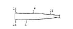
該収容筒2は、図4に示すように、一端が閉塞され、他端が開口された細長い円筒体に形成されている。該収容筒2は、合成樹脂などの透明材料より形成されている。尚、上記収容筒2の材料は、透明材料に限られず、有色半透明材料など各種の材料であってもよいことは勿論である。
【0033】
上記収容筒2は、図4の左側のほぼ半部の本体部21と、図4の右側のほぼ半部の先細部22とよりなり、尿検査装置にセット可能な外径及び長さのスピッツに構成されている。
【0034】
上記収容筒2の本体部21は、先細部22に向かって僅かに細くなるテーパ状に形成され、開口端部の外周面には、採尿筒3を固定するためのネジ23が形成されている。上記収容筒2の先細部22は、本体部21に連続し、閉塞端に向かって細くなるテーパ状に形成されている。上記収容筒2の先細部22は、本体部21のテーパ角度より大きく形成されている。
【0035】
上記収容筒2の先細部22の先端部には、第1の標線2aと第2の標線2aと形成されている。上記第1の標線2a及び第2の標線2aは、採取した尿を遠心分離して上澄を捨て、尿沈渣試験用のサンプル(15μl;マイクロリットル)を採取するための残尿量を表示するものであって、それぞれ0.1ml及び0.2mlの収納量を表示するように設定されている。
【0036】
上記収容筒2には、採尿量を示す採尿目盛り2bが付されている。該採尿目盛り2bは、収容筒2の長手方向に付され、採尿量が識別できるように構成されている。
【0037】
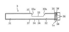
上記採尿筒3は、図5〜7に示すように、一端が閉塞され、他端が開口された細長い円筒体に形成されている。該採尿筒3は、合成樹脂などの半透明材料より形成されている。尚、上記採尿筒3の材料は、半透明材料に限られず、無着色合成樹脂など各種の材料であってもよいことは勿論である。
【0038】
上記採尿筒3は、図5の左側のほぼ半部の計量部31と、図5の右側のほぼ半部の採尿部32とより形成されている。上記計量部31は、一端が閉塞され、尿検査に必要な尿を計量するように構成されている。例えば、上記採尿筒3の計量部31は、10ml(ミリリットル)の収容容積に構成され、この容量の場合、上記計量部31は、例えば、内径が13.8mmの円筒体に形成され、長さが69.00mmに形成されている。尚、この計量部31の収容容積は、15ml(ミリリットル)や20ml(ミリリットル)であってもよく、要するに、上記計量部31の収容容積は、検査等の要望に対応して10ml(ミリリットル)以上であってもよく、逆に10ml(ミリリットル)未満であってもよい。
【0039】
上記採尿筒3の採尿部32は、一端が計量部31に連続し、他端が開口された円筒体に形成されている。そして、上記採尿部32は、採尿口33と補助口34とが形成されている。該採尿口33は、尿の採取時に該尿が注入される開口であって、採尿筒3の外周面から内周面に貫通して形成されている。上記採尿口33は、採尿筒3の円周方向の過半部を切り欠いて形成され、例えば、軸方向長さが30.00mmに形成されている。
【0040】
上記採尿口33における計量部31の側の一端は、採尿筒3の径方向に一致する直交面33aに形成され、他端は、開口端に向かって傾斜する傾斜面33bに形成されている。そして、上記採尿口33の直交面33aから採尿筒3の閉塞端までが上記計量部31に形成されている。
【0041】
上記補助口34は、採尿口33と反対側の採尿筒3の外周面から内周面に貫通して形成されている。上記補助口34は、2つ軸方向に直列に形成されている。尚、上記補助口34の個数は、1つであってよく、逆に3つ以上であってもよい。また、上記補助口34を形成した理由は、採尿時の空気抜き作用を行うようにして採尿の容易化を図るようにすると共に、成形時の変形を防止するようにするためである。
【0042】
更に、上記採尿部32の開口端部には、収容筒2の取付部35が形成されている。該取付部35は、採尿部32の外径より大径に形成され、上記収容筒2の開口端部が挿入及び抜取り自在に形成されている。
【0043】
上記取付部35の内周面には、収容筒2のネジ23にネジ込まれるネジ36が形成されている。そして、上記収容筒2のネジ23と採尿筒6のネジ36とによって収容筒2と採尿筒6とが取り付け及び取り外し自在に構成されている。上記収容筒2のネジ23と採尿筒6のネジ36とは、例えば、収容筒2と採尿筒6とを相対的に1回転又は1/2回転若しくは3/4回転で取り付け及び取り外しが行われるように構成されている。
【0044】
上記採尿筒3の外周面には、2つの第1突起37と第2突起38とが形成されている。該第1突起37は、カバー筒4の端部に尿が逆流しないように液止めするためと、カバー筒4を固定するための突起で、帯状に採尿筒3の全周に亘って形成されている。また、上記第2突起38は、カバー筒4の外部に尿が漏洩しないように液止めするためと、カバー筒4を固定するための突起で、帯状に採尿筒3の全周に亘って形成されている。上記第1突起37は、採尿口33の近傍における計量部31の外周面に形成され、第2突起38は、取付部35の外周面に形成されている。
【0045】
上記カバー筒4は、図8に示すように、一端が閉塞され、他端が開口された細長い円筒体に形成されている。該カバー筒4は、合成樹脂などの着色材料より形成されている。尚、上記採尿筒3の材料は、着色材料に限られず、各種の材料であってもよいことは勿論である。
【0046】
上記カバー筒4は、採尿筒3の挿入及び抜き取りが自在になるように該採尿筒3より僅かに大径に形成されている。
【0047】
上記カバー筒4は、採尿口33を閉鎖して採尿筒3の全体が挿入される長さに形成されたカバー本体41と、該カバー本体41の開口端部に形成された大径部42とより構成されている。該大径部42の内周面には、上記採尿筒3の第2突起38が嵌り込む凹部43が形成されている。
【0048】
上記カバー本体41は、採尿筒3の第1突起37が摺動接触する内径に形成され、採尿筒3の採尿口33から流れ出た尿がカバー筒4の閉塞端側に逆流しないように構成されている。上記カバー筒4の凹部43は、帯状に全周に形成され、採尿筒3をカバー筒4に挿入した際、収容筒2の第2突起38が嵌り込むように形成されている。
【0049】
上記カバー筒4の凹部43採尿筒3の第2突起38とが結合手段1aを構成し、収容筒2を採尿筒3及びカバー筒4より外す際、カバー筒4を収容筒2より引っ張ると、採尿筒3にカバー筒4が結合したまま同時に収容筒2より外れるように構成されている。
【0050】
また、上記カバー筒4の凹部43採尿筒3の第2突起38とは、カバー筒4の外部に尿が漏洩しないように液止めするシール機構を構成している。
【0051】
また、上記採尿用容器1は、収容筒2のキャップ5を備えている。該キャップ5は、図9に示すように、断面逆U字状に形成された本体51を備えている。そして、上記キャップ5における筒部の内周面には、収容筒2のネジ23にネジ込まれるネジ52が形成されている。上記キャップ51は、収容筒2の開口端部が挿入され、ネジ23とネジ52とネジ合わせて収容筒2を完全閉鎖するように形成されている。
【0052】
〈採尿用容器1の使用方法〉
次に、上述した採尿用容器11の使用方法について説明する。
【0053】
先ず、採尿時において、図1に示すように、採尿筒3の取付部35に収容筒2の開口端部を挿入して採尿筒3のネジ36と収容筒2のネジ23とネジ合わせて該採尿筒3と収容筒2とを取り付け、採尿状態に組み立てる。
【0054】
この組み立てた状態において、被検査者は、採尿筒3を下方に向けて収容筒2を把持する。そして、該被検査者は、採尿口33に尿を掛けることにより、該尿が採尿口33より採尿筒3に流入し、計量部31に溜まり、尿の採取が終了する。この採尿時において、所定量(例えば、10ml)の尿が計量部31に注入されると、採尿口33より採尿筒3の外に漏れるので、尿検査に必要な量が確実に採取され、余剰の尿が採取されることがない。
【0055】
この尿の採取が終了すると、採尿用容器1を検査室等に搬送する。その際の搬送状態は、2つの形態がある。
【0056】
1つの形態は、図2に示すように、上記採尿筒3を下方に向けたままカバー筒4に挿入する。この結果、汚れ部分である採尿筒3が覆われる。その際、上記カバー筒4に採尿筒3を挿入すると、採尿口33がカバー筒4によって閉鎖されると共に、挿入完了時に第2突起38とカバー筒4の凹部43とが嵌り込む。この第2突起38と凹部43との係合によって採尿の漏れが防止される。また、上記カバー本体41と採尿筒3の第1突起37とが接触しているので、採尿筒3の採尿口33から流れ出た尿がカバー筒4の閉塞端側に逆流することはない。よって、上記カバー筒4に残存する尿が生じないので、検査時の採尿不足が防止される。
【0057】
続いて、上記採尿用容器1の上下を逆にし、収容筒2を下側に向けて容器立て等に挿入して検査室等に搬送される。その際、上記採尿筒3を上下を逆にすると、計量部31の採尿が収容筒2に流れ、該尿が収容筒2に収納される。
【0058】
その後、検査室等において、上記採尿筒3の第2突起38とカバー筒4の凹部43とが係合しているので、カバー筒4を収容筒2に対して回転すると、ネジ23,36が外れる。このネジ23,36が外れた状態において、収容筒2が採尿筒3とカバー筒4とより外れる。
【0059】
この収容筒2を採尿筒3及びカバー筒4より外す際、カバー筒4を収容筒2より引っ張ると、採尿筒3にカバー筒4が結合手段1aによって結合したまま同時に収容筒2より外れる。この結果、上記尿が収容された収容筒2のみを検査装置にセットすることになる。
【0060】
一方、上記搬送状態の他の形態は、図3に示すように、収容筒2にキャップ5を取り付けて搬送する形態である。その際においても、採尿が終了すると、上記採尿筒3を下方に向けたままカバー筒4に挿入する。このカバー筒4に採尿筒3を挿入すると、採尿口33がカバー筒4によって閉鎖されると共に、第2突起38と凹部43とが係合する。
【0061】
その後、上記採尿筒3を上下を逆にすると、計量部31の採尿が収容筒2に流れ、該尿が収容筒2に収納される。この状態において、採尿筒3と収容筒2のネジ36,23を外し、カバー筒4を収容筒2より引っ張ると、採尿筒3及びカバー筒4が同時に収容筒2より外れる。この結果、上記尿が収容された収容筒2のみとなり、この収容筒2の開口端にキャップ5をネジ込んで密封し、容器立て等に立てて検査室等に搬送される。この検査室等では、キャップ5を収容筒2より外し、該収容筒2を検査装置にセットすることになる。
【0062】
〈実施形態1の効果〉
以上のように、本実施形態によれば、採尿筒3に計量部31を形成するようにしたために、検査に必要な量の尿採取を確実に行うことができる。この結果、検査室等において、余剰の尿の処理を行うことないので、検査を衛生的に且つ迅速に行うことができる。
【0063】
また、上記カバー筒4と採尿筒3との結合するようにしたので、汚れ部分に触れることなく、採尿筒3とカバー筒4とを同時に収容筒2より取り外すことができるので、極めて衛生的に採尿を行うことができる。
【0064】
また、上記採尿筒3をカバー筒4で覆うようにしたために、被検査者は採尿の際、採尿口33に尿を掛けるのみでもって尿を採取することができる。この結果、尿が手等に掛かることなく尿を採取することができるので、極めて衛生的に採尿することができる。
【0065】
また、上記収容筒2に開口等を形成していないので、採取した尿を遠心分離して検査する際、スピッツに移し替える必要がない。この結果、収容筒2をそのまま検査装置に適用することができることから、検査の迅速化を図ることができる。
【0066】
また、上記収容筒2には採尿目盛り2bが付されていることから、採尿量を正確に識別することができるので、検査時の検査記録等を容易に作成することができる。
【0067】
【発明の実施の形態2】
次に、本発明の実施形態2を図面に基づいて詳細に説明する。
【0068】
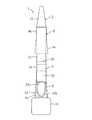
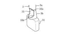
本実施形態は、図10〜図12に示すように、実施形態1のカバー筒4が採尿筒3の全体を覆うようにしたのに代えて、カバー筒4が採尿口33のみを閉鎖するように形成したものである。
【0069】
具体的に、採尿筒3の計量部31は、矩形体のタンク状に形成されている。そして、上記計量部31の上面には、採尿部32が連続形成されている。該採尿部32は、テーパ部3aと真円部3bとより形成されている。該テーパ部3aは、図10において下方に向かって大径となるテーパ状に形成され、大径端が上記計量部31に連続し、小径端に真円部3bが連続形成されている。上記テーパ部3aには、採尿口33が形成され、該採尿口33は、下端面が傾斜面33bに形成され、上端面が直交面33aに形成されている。
【0070】
上記真円部3bは、図10の上端部に取付部35が形成され、収容筒2が取り付けられるように形成されている。
【0071】
一方、上記カバー筒4は、採尿筒3の採尿部32に対応してテーパ部4aと真円部4bとより形成されている。上記カバー筒4のテーパ部4aは、図10において、下方に向かって大径となるテーパ状に形成され、小径端に真円部4bが連続形成されている。上記カバー筒4の真円部4bは、収容筒2に挿入されており、該収納筒及び採尿部32の真円部3bを摺接して移動するように形成されている。
【0072】
そして、上記カバー筒4は、収容筒2から採尿筒3にスライドさせると、採尿筒3のテーパ部3aに嵌り込み採尿口33を閉鎖するように形成されている。
【0073】
尚、キャップ5は、小径の挿入部53と、大径のフランジ部54とを備えている。上記挿入部53は、収容筒2の開口端部に挿入されて該収容筒2を閉鎖するように形成されている。
【0074】
したがって、採尿時において、図10に示すように、採尿筒3の取付部35に収容筒2の開口端部を挿入して該採尿筒3と収容筒2とを取り付け、採尿状態に組み立てる。
【0075】
この組み立てた状態において、カバー筒4は、収容筒2の外側に位置しており、採尿口33が開口した状態となっている。そして、被検査者は、採尿筒3を下方に向けて収容筒2を把持する。被検査者は、採尿口33に尿を掛けることにより、該尿が採尿口33より採尿筒3に流入し、計量部31に溜まり、尿の採取が終了する。この採尿時において、所定量(10ml)の尿が計量部31に注入されると、採尿口33より採尿筒3の外に漏れるので、尿検査に必要な量が確実に採取され、余剰の尿が採取されることがない。
【0076】
この尿の採取が終了すると、汚れていないカバー筒4を押し下げ、カバー筒4のテーパ部4aを採尿筒3のテーパ部3aに嵌め込むと、採尿口33がカバー等で閉鎖されることになる。続いて、上記カバー筒4を把持して上記採尿用容器1の上下を逆にすると、計量部31の採尿が収容筒2に流れ、該尿が収容筒2に収納される。
【0077】
その後、この状態において、容器立て等に挿入して検査室等に搬送してもよい。また、図11に示すように、収容筒2から採尿筒3及びカバー筒4を抜き取り、キャップ5によって収容筒2の開口端を閉鎖し、容器立て等に挿入して検査室等に搬送してもよい。その他の構成、作用及び効果は、実施形態1と同様である。
【0078】
【発明の実施の形態3】
次に、本発明の実施形態3を図面に基づいて詳細に説明する。
【0079】
本実施形態は、図13〜図15に示すように、実施形態2の計量部31が矩形体のタンク状にしたのに代えて、楕円状の筒体に形成したものである。
【0080】
具体的に、採尿筒3の計量部31は、採尿部32のテーパ部3aに連続し、図13において、下方に向かって大径となるテーパ状に形成され、大径端が閉鎖されている。そして、上記計量部31の上端である小径端に採尿部32のテーパ部3aの大径端が連続している。
【0081】
したがって、採尿時において、図13に示すように、採尿筒3の取付部35に収容筒2の開口端部を挿入して該採尿筒3と収容筒2とを取り付け、採尿状態に組み立てる。
【0082】
この組み立てた状態において、カバー筒4は、収容筒2の外側に位置しており、採尿口33が開口した状態となっている。そして、被検査者は、採尿筒3を下方に向けて収容筒2を把持する。被検査者は、採尿口33に尿を掛けることにより、該尿が採尿口33より採尿筒3に流入し、計量部31に溜まり、尿の採取が終了する。この採尿時において、所定量(10ml)の尿が計量部31に注入されると、採尿口33より採尿筒3の外に漏れるので、尿検査に必要な量が確実に採取され、余剰の尿が採取されることがない。
【0083】
この尿の採取が終了すると、汚れていないカバー筒4を押し下げ、カバー筒4のテーパ部4aを採尿筒3のテーパ部3aに嵌め込むと、採尿口33がカバー等で閉鎖されることになる。続いて、上記カバー筒4を把持して上記採尿用容器1の上下を逆にすると、計量部31の採尿が収容筒2に流れ、該尿が収容筒2に収納される。
【0084】
その後、この状態において、容器立て等に挿入して検査室等に搬送してもよい。また、図14に示すように、収容筒2から採尿筒3及びカバー筒4を抜き取り、キャップ5によって収容筒2の開口端を閉鎖し、容器立て等に挿入して検査室等に搬送してもよい。その他の構成、作用及び効果は、実施形態2と同様である。
【0085】
【発明の他の実施の形態】
上記実施形態においては、収容筒2のネジ23と採尿筒6のネジ36とを形成したが、この収容筒2のネジ23と採尿筒6のネジ36とは、凹部と凸部との組合せであってもよく、要するに上記収容筒2と採尿筒6とが尿が漏れることなく取り付け及び取り外しが行われるように構成されておればよい。
【図面の簡単な説明】
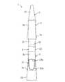
【図1】本発明の実施例1を示し、カバー筒を外した採尿用容器の正面図である。
【図2】本発明の実施例1を示し、カバー筒を取り付けた採尿用容器の縦断面図である。
【図3】本発明の実施例1を示し、キャップを取り付けた収容筒の縦断面図である。
【図4】本発明の実施例1を示す収容筒の縦断面図である。
【図5】本発明の実施例1を示す採尿筒の側面図である。
【図6】本発明の実施例1を示す採尿筒の縦断面図である。
【図7】本発明の実施例1を示す図5のA−A線における断面図である。
【図8】本発明の実施例1を示すカバー筒の縦断面図である。
【図9】本発明の実施例1を示すキャップの側面図である。
【図10】本発明の実施例2を示し、採尿前の採尿用容器の正面図である。
【図11】本発明の実施例2を示し、採尿後の採尿用容器の縦断面図である。
【図12】本発明の実施例2を示し、採尿筒の一部の斜視図である。
【図13】本発明の実施例3を示し、採尿前の採尿用容器の正面図である。
【図14】本発明の実施例3を示し、採尿後の採尿用容器の縦断面図である。
【図15】本発明の実施例3を示し、採尿筒の平面図である。
【符号の説明】
1 採尿用容器
1a 結合手段
2 収容筒
3 採尿筒
31 計量部
32 採尿部
33 採尿口
4 カバー筒
5 キャップ[0001]
BACKGROUND OF THE INVENTION
The present invention relates to a urine collection container used for urinalysis performed in hospitals, examination centers and the like.
[0002]
[Prior art]
In general, many urine tests are performed in hospitals and examination centers.
[0003]
Conventionally, the urine collection container used for the urinalysis includes a cylindrical container body in which a urine collection port is formed, and an open end portion of the container body, as disclosed in International Publication No. WO95 / 09362. And a cap that is detachable, and a cover cylinder that is formed so that the container body can be freely inserted and removed.
[0004]
In addition, as disclosed in the above-mentioned WO95 / 09362, the other urine collection container is formed to be detachable from the cylindrical container body and the opening end of the container body. There is a configuration in which a cap formed with a mouth and a cover tube formed so that the container body can be inserted and removed freely.
[0005]
In these urine collection containers, at the time of urine collection, a cap is attached to the open end of the container body, and the examinee holds the cap with the container body facing downward. The urine is collected in the container body from the urine collection port by applying urine to the urine collection port. After collecting urine, the container body is inserted into the cover cylinder with the closed end side of the container body facing downward, and the cover cylinder closes the urine collection port.
[0006]
[Problems to be solved by the invention]
The urine collection container described above is inserted into a container stand or the like and conveyed to an examination room or the like in a state where the urine collection port is closed by the cover cylinder. However, the conventional urine collection container has a problem that the urine test in the laboratory is extremely complicated.
[0007]
Specifically, as one of the urine tests using the urine collection container, there is a method in which the cap is removed while the container body is inserted into the cover tube, and a reagent or the like is inserted from the open end of the container body. In addition, there is a method in which a cover tube is removed while a cap is attached to the container body, and a urine test is performed by inserting a reagent or the like from a urine collection port of the container body.
[0008]
However, since the conventional urine collection container is not configured with a measuring means, urine collection is performed up to the urine collection port of the cap, and there is a problem that it is difficult to perform an excessive urine collection process. That is, in the inspection apparatus, only the container main body is installed, but there are cases where urine is collected more than this container main body, and there is a problem that it takes time to install the container main body in the inspection apparatus.
[0009]
In particular, when a container body or the like is inserted into the cover cylinder after urine collection, if the amount of urine collection is large, urine in the container body may hang down from the opening edge of the cover cylinder to the outside of the cover cylinder. Therefore, there is a possibility that hands and the like are soiled.
[0010]
The present invention has been made in view of such a point, and an object thereof is to reliably perform urine collection necessary for examination.
[0011]
[Means for Solving the Problems]
In the first invention, one end is closed, the other end is formed at the open end, and an elongated cylindrical storage tube for storing urine, one end is formed at the closed end, and the other end is the opening of the storage tube. An elongated cylindrical urine collection tube for collecting urine with a urine collection port formed on the side surface, and an elongated tube with one end closed and the other end opened. And a cover cylinder for covering the urine collection port. The cover cylinder is formed so as to be slightly larger in diameter than the urine collection cylinder so that the urine collection cylinder can be freely inserted and removed. And from the urine collection port of the urine collection tube to the closed end, it is formed in a measuring part for storing and measuring a predetermined urine collection amount.
[0012]
Moreover, 2nd invention is set as the structure provided with the cap which closes the opening end of this storage cylinder in the state which isolate | separated the storage cylinder and the urine collection cylinder in 1st invention.
[0013]
In addition, a third invention is configured such that in the first or second invention, coupling means for detachably coupling the urine collection cylinder and the cover cylinder is provided.
[0014]
According to a fourth invention, in the third invention, the coupling means is formed on the protrusion formed on the outer peripheral surface of the urine collection tube and the inner peripheral surface of the cover tube, and is inserted when the urine collection tube is inserted into the cover tube. It is set as the structure provided with the recessed part into which the said protrusion fits.
[0015]
Moreover, 5th invention is set as the structure by which the urine collection scale which shows urine collection volume was attached | subjected to the said storage cylinder in 1st invention.
[0016]
That is, in the present invention, first, at the time of urine collection, the opening end of the housing cylinder is attached to the urine collection cylinder and assembled in the urine collection state.
[0017]
In this assembled state, the examinee grips the storage cylinder with the urine collection cylinder facing downward. Then, when the subject hangs urine on the urine collection port, the urine flows into the urine collection tube from the urine collection port, accumulates in the measuring unit, and urine collection is completed. At the time of this urine collection, if a predetermined amount, for example, 10 ml (milliliter) of urine is injected into the measuring section, it leaks out of the urine collection tube through the urine collection port, so that the amount necessary for urinalysis is reliably collected and surplus No urine is collected.
[0018]
When the collection of urine is completed, the urine collection container is transported to an examination room or the like. There are two forms of conveying states at that time.
[0019]
In one embodiment, the urine collection tube is inserted into the cover tube while facing downward. As a result, the urine collection cylinder which is a dirty part is covered. At this time, for example, when the urine collection tube is inserted into the cover tube, the urine collection port is closed by the cover tube, and the projection of the urine collection tube and the recess of the cover tube are fitted when the insertion is completed.
[0020]
Subsequently, the container for urine collection is turned upside down, and the container is inserted into a container stand or the like with the storage tube facing downward, and is transported to an examination room or the like. At that time, when the urine collection cylinder is turned upside down, the urine collection of the measuring section flows into the storage cylinder, and the urine is stored in the storage cylinder.
[0021]
Thereafter, the storage cylinder is removed from the urine collection cylinder and the cover cylinder in an examination room or the like. At this time, when the cover tube is pulled from the housing tube, the cover tube is detached from the housing tube at the same time while being coupled to the urine collection tube by the coupling means. Specifically, the protrusion and the recess are fitted, the urine collection cylinder and the cover cylinder are simultaneously detached from the storage cylinder, and only the storage cylinder in which the urine is stored is set in the inspection apparatus.
[0022]
On the other hand, the other form of the said conveyance state is a form which takes a cap in a storage cylinder and conveys. Even in this case, when the urine collection is completed, the urine collection cylinder is inserted into the cover cylinder while facing downward. When the urine collection tube is inserted into the cover tube, the urine collection port is closed by the cover tube, and the protrusion and the recess are engaged.
[0023]
Thereafter, when the urine collection tube is turned upside down, the urine collection of the measuring portion flows into the storage tube, and the urine is stored in the storage tube. In this state, when the cover cylinder is pulled from the accommodation cylinder, the cover cylinder is detached from the accommodation cylinder at the same time while the cover cylinder is coupled to the urine collection cylinder. Then, only the storage cylinder in which the urine is stored is used, and a cap is attached to the open end of the storage cylinder so as to be sealed, and the container is transferred to an examination room or the like in a container stand or the like. In this inspection room or the like, the cap is removed from the storage cylinder, and the storage cylinder is set in the inspection apparatus.
[0024]
【The invention's effect】
Therefore, according to the present invention, since the measuring portion is formed in the urine collection cylinder, it is possible to reliably collect the amount of urine necessary for the examination. As a result, surplus urine is not processed in an examination room or the like, so that the examination can be performed hygienically and quickly.
[0025]
Further, since the urine collection tube is covered with the cover tube, the subject can collect urine simply by placing urine on the urine collection port when collecting urine. As a result, since urine can be collected without urine getting on hands or the like, urine can be collected very hygienically.
[0026]
Moreover, since the opening etc. are not formed in the said storage cylinder, when centrifuges and test | inspecting the extract | collected urine, it is not necessary to transfer to Spitz. As a result, since the storage cylinder can be applied to the inspection apparatus as it is, the inspection can be speeded up.
[0027]
In addition, when the cover tube and the urine collection tube are combined, the cover tube and the urine collection tube can be removed from the storage tube at the same time without touching the dirt portion, so that urine can be collected extremely hygienically. .
[0028]
Further, if the urine collection scale is attached to the housing cylinder, the urine collection amount can be accurately identified, so that an inspection record at the time of inspection can be easily created.
[0029]
DESCRIPTION OF THE
Hereinafter,
[0030]
1 to 9
[0031]
The
[0032]
As shown in FIG. 4, the
[0033]
The
[0034]
The
[0035]
A first
[0036]
The
[0037]
As shown in FIGS. 5 to 7, the
[0038]
The
[0039]
The
[0040]
One end of the
[0041]
The
[0042]
Further, an
[0043]
A
[0044]
Two
[0045]
As shown in FIG. 8, the
[0046]
The
[0047]
The
[0048]
The
[0049]
The
[0050]
Further, the
[0051]
The
[0052]
<Usage of
Next, a method for using the above-described urine collection container 11 will be described.
[0053]
First, at the time of urine collection, as shown in FIG. 1, the opening end portion of the
[0054]
In this assembled state, the examinee holds the
[0055]
When the collection of urine is completed, the
[0056]
In one form, as shown in FIG. 2, the
[0057]
Subsequently, the urine-collecting
[0058]
Thereafter, in the examination room or the like, the
[0059]
When removing the
[0060]
On the other hand, as shown in FIG. 3, another form of the transport state is a form in which a
[0061]
Thereafter, when the
[0062]
<Effect of
As described above, according to the present embodiment, since the measuring
[0063]
In addition, since the
[0064]
Further, since the
[0065]
In addition, since no opening or the like is formed in the
[0066]
Further, since the
[0067]
Second Embodiment of the Invention
Next, a second embodiment of the present invention will be described in detail based on the drawings.
[0068]
In this embodiment, as shown in FIGS. 10 to 12, instead of the
[0069]
Specifically, the measuring
[0070]
The
[0071]
On the other hand, the
[0072]
The
[0073]
The
[0074]
Therefore, at the time of urine collection, as shown in FIG. 10, the open end portion of the
[0075]
In this assembled state, the
[0076]
When the collection of urine is completed, when the
[0077]
Thereafter, in this state, it may be inserted into a container stand or the like and transported to an examination room or the like. Further, as shown in FIG. 11, the
[0078]
Next,
[0079]
In this embodiment, as shown in FIGS. 13 to 15, the measuring
[0080]
Specifically, the measuring
[0081]
Therefore, at the time of urine collection, as shown in FIG. 13, the opening end portion of the
[0082]
In this assembled state, the
[0083]
When the collection of urine is completed, when the
[0084]
Thereafter, in this state, it may be inserted into a container stand or the like and transported to an examination room or the like. Further, as shown in FIG. 14, the
[0085]
Other Embodiments of the Invention
In the above embodiment, the
[Brief description of the drawings]
FIG. 1 is a front view of a urine collection container with a cover cylinder removed, showing
FIG. 2 is a longitudinal sectional view of a urine collection container showing a first embodiment of the present invention and attached with a cover tube.
FIG. 3 is a vertical cross-sectional view of a storage cylinder with a cap attached thereto, showing
FIG. 4 is a vertical cross-sectional view of a storage
FIG. 5 is a side view of a urine collection cylinder showing Example 1 of the present invention.
FIG. 6 is a longitudinal sectional view of a urine collection cylinder showing Example 1 of the present invention.
7 is a cross-sectional view taken along line AA of FIG. 5 showing Example 1 of the present invention.
FIG. 8 is a longitudinal sectional view of a cover
FIG. 9 is a side view of a cap showing Example 1 of the present invention.
FIG. 10 is a front view of a urine collection container before urine collection, showing
FIG. 11 is a longitudinal sectional view of a urine collection container after urine collection, showing
FIG. 12 is a perspective view of a part of a urine collection cylinder, showing Example 2 of the present invention.
FIG. 13 is a front view of a urine collection container before urine collection, showing
FIG. 14 is a longitudinal sectional view of a urine collection container after urine collection, showing Example 3 of the present invention.
FIG. 15 is a plan view of a urine collection cylinder, showing
[Explanation of symbols]
1 Urine collection container
1a Joining means
2 container
3 Urine collection tubes
31 Weighing section
32 Urine collection part
33 Urine collection port
4 Cover tube
5 Cap
Claims (5)
Translated fromJapanese一端が閉塞端に形成され、他端が上記収容筒の開口端部の取り付け及び取り外しが自在な開口端に形成されると共に、側面に採尿口が形成されて採尿するための細長い筒状の採尿筒と、
一端が閉塞され、他端が開口された細長い筒状に形成されると共に、上記採尿筒の挿入及び抜き取りが自在に成るように該採尿筒より僅かに大径に形成され、上記採尿口を覆うためのカバー筒とを備え、
上記採尿筒の採尿口から閉塞端までは、所定の採尿量を収容して計量するための計量部に形成されている
ことを特徴とする採尿用容器。One end is closed, the other end is formed at the open end, and an elongated cylindrical storage tube for storing urine,
One end is formed as a closed end, and the other end is formed at an open end where the opening end of the housing cylinder can be freely attached and detached, and a urine collection port is formed on the side surface to collect urine. A tube,
The urine collection tube is formed in a long and narrow shape with one end closed and the other end opened, and has a slightly larger diameter than the urine collection tube so that the urine collection tube can be freely inserted and removed, and covers the urine collection port. And a cover cylinder for
The urine collection container is characterized in that a portion from the urine collection port to the closed end of the urine collection tube is formed in a measuring unit for storing and measuring a predetermined urine collection amount.
収容筒と採尿筒とを分離した状態で、該収容筒の開口端を閉鎖するキャップを備えている
ことを特徴とする採尿用容器。In claim 1,
A urine collection container comprising a cap for closing an open end of the storage cylinder in a state where the storage cylinder and the urine collection cylinder are separated.
上記採尿筒とカバー筒とを着脱自在に結合する結合手段が設けられている
ことを特徴とする採尿用容器。In claim 1 or 2,
A urine collection container, characterized in that a coupling means for detachably coupling the urine collection cylinder and the cover cylinder is provided.
上記結合手段は、採尿筒の外周面に形成された突起と、上記カバー筒の内周面に形成され、採尿筒のカバー筒に対する挿入時に上記突起が嵌り込む凹部とを備えている
ことを特徴とする採尿用容器。In claim 3,
The coupling means includes a protrusion formed on the outer peripheral surface of the urine collection tube and a recess formed on the inner peripheral surface of the cover tube and into which the protrusion fits when inserted into the cover tube of the urine collection tube. Urine collection container.
上記収容筒には、採尿量を示す採尿目盛りが付されている
ことを特徴とする採尿用容器。In claim 1,
A urine collection container, wherein the storage cylinder is provided with a urine collection scale indicating the amount of urine collection.
Priority Applications (2)
| Application Number | Priority Date | Filing Date | Title |
|---|---|---|---|
| JP2002011939AJP3708879B2 (en) | 2002-01-21 | 2002-01-21 | Urine collection container |
| PCT/JP2003/001425WO2004072637A1 (en) | 2002-01-21 | 2003-02-12 | Urine sampling container |
Applications Claiming Priority (2)
| Application Number | Priority Date | Filing Date | Title |
|---|---|---|---|
| JP2002011939AJP3708879B2 (en) | 2002-01-21 | 2002-01-21 | Urine collection container |
| PCT/JP2003/001425WO2004072637A1 (en) | 2002-01-21 | 2003-02-12 | Urine sampling container |
Publications (2)
| Publication Number | Publication Date |
|---|---|
| JP2003215121A JP2003215121A (en) | 2003-07-30 |
| JP3708879B2true JP3708879B2 (en) | 2005-10-19 |
Family
ID=33133202
Family Applications (1)
| Application Number | Title | Priority Date | Filing Date |
|---|---|---|---|
| JP2002011939AExpired - LifetimeJP3708879B2 (en) | 2002-01-21 | 2002-01-21 | Urine collection container |
Country Status (2)
| Country | Link |
|---|---|
| JP (1) | JP3708879B2 (en) |
| WO (1) | WO2004072637A1 (en) |
Families Citing this family (8)
| Publication number | Priority date | Publication date | Assignee | Title |
|---|---|---|---|---|
| JP4401845B2 (en)* | 2004-04-06 | 2010-01-20 | 株式会社札幌イムノ・ダイアグノスティック・ラボラトリー | Sample test container set and sample test kit |
| US7214199B1 (en)* | 2006-03-29 | 2007-05-08 | B. Well Veterinary Products, Inc. | Urine analysis collection kit for veterinary use |
| WO2009018473A1 (en)* | 2007-07-31 | 2009-02-05 | Micronics, Inc. | Sanitary swab collection system, microfluidic assay device, and methods for diagnostic assays |
| JP4953980B2 (en)* | 2007-08-20 | 2012-06-13 | 株式会社アトレータ | Urine collection container |
| JP5802899B2 (en)* | 2011-08-11 | 2015-11-04 | 株式会社アトレータ | Urine collection container |
| JP2015049202A (en)* | 2013-09-04 | 2015-03-16 | 禮子 辻 | Container for urine collection |
| JP6643042B2 (en)* | 2015-10-26 | 2020-02-12 | 株式会社アトレータ | Urine collection container |
| CN107340151B (en)* | 2017-08-29 | 2023-06-09 | 杭州同创越诚基因科技有限公司 | Quantitative fecal sample collection device and collection method |
Family Cites Families (4)
| Publication number | Priority date | Publication date | Assignee | Title |
|---|---|---|---|---|
| JPS5826934U (en)* | 1981-08-11 | 1983-02-21 | 佐々木 豊子 | sample container |
| JPH07167857A (en)* | 1991-11-08 | 1995-07-04 | Kaoru Shimizu | Stick for collecting urine |
| JP2884126B2 (en)* | 1992-11-05 | 1999-04-19 | 幸一郎 斉藤 | Urine collection container |
| WO1995009362A1 (en)* | 1993-09-30 | 1995-04-06 | Fujisawa Pharmaceutical Co., Ltd. | Urine sampling vessel |
- 2002
- 2002-01-21JPJP2002011939Apatent/JP3708879B2/ennot_activeExpired - Lifetime
- 2003
- 2003-02-12WOPCT/JP2003/001425patent/WO2004072637A1/enactiveApplication Filing
Also Published As
| Publication number | Publication date |
|---|---|
| JP2003215121A (en) | 2003-07-30 |
| WO2004072637A1 (en) | 2004-08-26 |
Similar Documents
| Publication | Publication Date | Title |
|---|---|---|
| US4066414A (en) | One piece tube and microscope slide manipulative laboratory device | |
| WO2005008216A2 (en) | Sanitary fluid collection, application and storage device and methods of use of same | |
| JP3622827B2 (en) | Stool collection container | |
| CN111157717B (en) | A detection device | |
| US10551373B2 (en) | Urine test device | |
| JP3708879B2 (en) | Urine collection container | |
| US20040025603A1 (en) | Test tube insert | |
| JP4308943B2 (en) | Collection container assembly | |
| JP4953980B2 (en) | Urine collection container | |
| JP5802899B2 (en) | Urine collection container | |
| JPH10185912A (en) | Feces examination kit | |
| US20040025935A1 (en) | Test tube insert | |
| US20060142669A1 (en) | Urine sampling container | |
| JPH11295194A (en) | Feces collecting container | |
| CN208769829U (en) | Mid-section urine collection and detection assembly and mid-section urine collection and detection device | |
| CN210401430U (en) | Fecal occult blood detection device | |
| CN118483000A (en) | Multifunctional urine collection cup | |
| CN218279688U (en) | A sampling device for medical examination | |
| JPH07225230A (en) | Inspection equipment with specimen collecting equipment | |
| US20140363353A1 (en) | Fast flow apparatus and method to evaluate analtyes in liquid, solid and semisolid samples | |
| CN206132445U (en) | Urinate conventional sample and leave and take device | |
| CN219353979U (en) | Urine collector | |
| CN215078945U (en) | Prevent urine storage pipe that spills and leak | |
| CN219122048U (en) | Self-testing sampling detection device | |
| CN210720400U (en) | Intelligent closestool system for urine sampling and detection |
Legal Events
| Date | Code | Title | Description |
|---|---|---|---|
| A621 | Written request for application examination | Free format text:JAPANESE INTERMEDIATE CODE: A621 Effective date:20041221 | |
| A977 | Report on retrieval | Free format text:JAPANESE INTERMEDIATE CODE: A971007 Effective date:20050714 | |
| TRDD | Decision of grant or rejection written | ||
| A01 | Written decision to grant a patent or to grant a registration (utility model) | Free format text:JAPANESE INTERMEDIATE CODE: A01 Effective date:20050726 | |
| A61 | First payment of annual fees (during grant procedure) | Free format text:JAPANESE INTERMEDIATE CODE: A61 Effective date:20050804 | |
| R150 | Certificate of patent or registration of utility model | Ref document number:3708879 Country of ref document:JP Free format text:JAPANESE INTERMEDIATE CODE: R150 Free format text:JAPANESE INTERMEDIATE CODE: R150 | |
| FPAY | Renewal fee payment (event date is renewal date of database) | Free format text:PAYMENT UNTIL: 20090812 Year of fee payment:4 | |
| R250 | Receipt of annual fees | Free format text:JAPANESE INTERMEDIATE CODE: R250 | |
| FPAY | Renewal fee payment (event date is renewal date of database) | Free format text:PAYMENT UNTIL: 20090812 Year of fee payment:4 | |
| FPAY | Renewal fee payment (event date is renewal date of database) | Free format text:PAYMENT UNTIL: 20100812 Year of fee payment:5 | |
| R250 | Receipt of annual fees | Free format text:JAPANESE INTERMEDIATE CODE: R250 | |
| FPAY | Renewal fee payment (event date is renewal date of database) | Free format text:PAYMENT UNTIL: 20110812 Year of fee payment:6 | |
| R250 | Receipt of annual fees | Free format text:JAPANESE INTERMEDIATE CODE: R250 | |
| FPAY | Renewal fee payment (event date is renewal date of database) | Free format text:PAYMENT UNTIL: 20120812 Year of fee payment:7 | |
| R250 | Receipt of annual fees | Free format text:JAPANESE INTERMEDIATE CODE: R250 | |
| FPAY | Renewal fee payment (event date is renewal date of database) | Free format text:PAYMENT UNTIL: 20120812 Year of fee payment:7 | |
| FPAY | Renewal fee payment (event date is renewal date of database) | Free format text:PAYMENT UNTIL: 20130812 Year of fee payment:8 | |
| R250 | Receipt of annual fees | Free format text:JAPANESE INTERMEDIATE CODE: R250 | |
| R250 | Receipt of annual fees | Free format text:JAPANESE INTERMEDIATE CODE: R250 | |
| R250 | Receipt of annual fees | Free format text:JAPANESE INTERMEDIATE CODE: R250 | |
| R250 | Receipt of annual fees | Free format text:JAPANESE INTERMEDIATE CODE: R250 | |
| R250 | Receipt of annual fees | Free format text:JAPANESE INTERMEDIATE CODE: R250 | |
| R250 | Receipt of annual fees | Free format text:JAPANESE INTERMEDIATE CODE: R250 | |
| R250 | Receipt of annual fees | Free format text:JAPANESE INTERMEDIATE CODE: R250 | |
| R250 | Receipt of annual fees | Free format text:JAPANESE INTERMEDIATE CODE: R250 | |
| R250 | Receipt of annual fees | Free format text:JAPANESE INTERMEDIATE CODE: R250 | |
| R250 | Receipt of annual fees | Free format text:JAPANESE INTERMEDIATE CODE: R250 | |
| EXPY | Cancellation because of completion of term |