JP3708793B2 - Semiconductor film fabrication method - Google Patents
Semiconductor film fabrication methodDownload PDFInfo
- Publication number
- JP3708793B2 JP3708793B2JP2000144672AJP2000144672AJP3708793B2JP 3708793 B2JP3708793 B2JP 3708793B2JP 2000144672 AJP2000144672 AJP 2000144672AJP 2000144672 AJP2000144672 AJP 2000144672AJP 3708793 B2JP3708793 B2JP 3708793B2
- Authority
- JP
- Japan
- Prior art keywords
- laser beam
- cylindrical
- semiconductor film
- laser
- lens
- Prior art date
- Legal status (The legal status is an assumption and is not a legal conclusion. Google has not performed a legal analysis and makes no representation as to the accuracy of the status listed.)
- Expired - Fee Related
Links
- 239000004065semiconductorSubstances0.000titleclaimsdescription22
- 238000000034methodMethods0.000titleclaimsdescription13
- 238000004519manufacturing processMethods0.000titleclaims4
- 239000000758substrateSubstances0.000claimsdescription22
- 239000011521glassSubstances0.000claimsdescription17
- 230000003287optical effectEffects0.000claimsdescription14
- 230000001678irradiating effectEffects0.000claimsdescription4
- 238000005224laser annealingMethods0.000description18
- XUIMIQQOPSSXEZ-UHFFFAOYSA-NSiliconChemical compound[Si]XUIMIQQOPSSXEZ-UHFFFAOYSA-N0.000description11
- 239000012535impuritySubstances0.000description11
- 229910052710siliconInorganic materials0.000description11
- 239000010703siliconSubstances0.000description11
- 229910052698phosphorusInorganic materials0.000description9
- 239000011574phosphorusSubstances0.000description9
- OAICVXFJPJFONN-UHFFFAOYSA-NPhosphorusChemical compound[P]OAICVXFJPJFONN-UHFFFAOYSA-N0.000description8
- 229910052796boronInorganic materials0.000description8
- 150000002500ionsChemical class0.000description8
- ZOXJGFHDIHLPTG-UHFFFAOYSA-NBoronChemical group[B]ZOXJGFHDIHLPTG-UHFFFAOYSA-N0.000description7
- 230000004913activationEffects0.000description7
- 238000000576coating methodMethods0.000description6
- 239000011248coating agentSubstances0.000description5
- VYPSYNLAJGMNEJ-UHFFFAOYSA-NSilicium dioxideChemical compoundO=[Si]=OVYPSYNLAJGMNEJ-UHFFFAOYSA-N0.000description3
- 238000010586diagramMethods0.000description3
- 229910021480group 4 elementInorganic materials0.000description3
- 229910052814silicon oxideInorganic materials0.000description3
- XYFCBTPGUUZFHI-UHFFFAOYSA-NPhosphineChemical compoundPXYFCBTPGUUZFHI-UHFFFAOYSA-N0.000description2
- 230000001133accelerationEffects0.000description2
- 238000000137annealingMethods0.000description2
- 239000013078crystalSubstances0.000description2
- 238000005516engineering processMethods0.000description2
- 238000005468ion implantationMethods0.000description2
- -1phosphorus ionsChemical class0.000description2
- 229910052581Si3N4Inorganic materials0.000description1
- 229910000577Silicon-germaniumInorganic materials0.000description1
- LEVVHYCKPQWKOP-UHFFFAOYSA-N[Si].[Ge]Chemical compound[Si].[Ge]LEVVHYCKPQWKOP-UHFFFAOYSA-N0.000description1
- 229910045601alloyInorganic materials0.000description1
- 239000000956alloySubstances0.000description1
- 229910021417amorphous siliconInorganic materials0.000description1
- 230000003321amplificationEffects0.000description1
- 238000002425crystallisationMethods0.000description1
- 230000008025crystallizationEffects0.000description1
- 230000000694effectsEffects0.000description1
- 229910052732germaniumInorganic materials0.000description1
- GNPVGFCGXDBREM-UHFFFAOYSA-Ngermanium atomChemical compound[Ge]GNPVGFCGXDBREM-UHFFFAOYSA-N0.000description1
- BHEPBYXIRTUNPN-UHFFFAOYSA-Nhydridophosphorus(.) (triplet)Chemical compound[PH]BHEPBYXIRTUNPN-UHFFFAOYSA-N0.000description1
- 230000001771impaired effectEffects0.000description1
- 238000003199nucleic acid amplification methodMethods0.000description1
- 238000005457optimizationMethods0.000description1
- 230000010355oscillationEffects0.000description1
- 229910000073phosphorus hydrideInorganic materials0.000description1
- 238000005268plasma chemical vapour depositionMethods0.000description1
- 238000003672processing methodMethods0.000description1
- 238000007493shaping processMethods0.000description1
- 229910010271silicon carbideInorganic materials0.000description1
- HBMJWWWQQXIZIP-UHFFFAOYSA-Nsilicon carbideChemical compound[Si+]#[C-]HBMJWWWQQXIZIP-UHFFFAOYSA-N0.000description1
- HQVNEWCFYHHQES-UHFFFAOYSA-Nsilicon nitrideChemical compoundN12[Si]34N5[Si]62N3[Si]51N64HQVNEWCFYHHQES-UHFFFAOYSA-N0.000description1
- 239000001394sodium malateSubstances0.000description1
- 238000004544sputter depositionMethods0.000description1
Images


Classifications
- H—ELECTRICITY
- H01—ELECTRIC ELEMENTS
- H01L—SEMICONDUCTOR DEVICES NOT COVERED BY CLASS H10
- H01L21/00—Processes or apparatus adapted for the manufacture or treatment of semiconductor or solid state devices or of parts thereof
- H01L21/02—Manufacture or treatment of semiconductor devices or of parts thereof
- H01L21/02104—Forming layers
- H01L21/02365—Forming inorganic semiconducting materials on a substrate
- H01L21/02656—Special treatments
- H01L21/02664—Aftertreatments
- H01L21/02667—Crystallisation or recrystallisation of non-monocrystalline semiconductor materials, e.g. regrowth
- H01L21/02675—Crystallisation or recrystallisation of non-monocrystalline semiconductor materials, e.g. regrowth using laser beams
- H01L21/02686—Pulsed laser beam
- C—CHEMISTRY; METALLURGY
- C23—COATING METALLIC MATERIAL; COATING MATERIAL WITH METALLIC MATERIAL; CHEMICAL SURFACE TREATMENT; DIFFUSION TREATMENT OF METALLIC MATERIAL; COATING BY VACUUM EVAPORATION, BY SPUTTERING, BY ION IMPLANTATION OR BY CHEMICAL VAPOUR DEPOSITION, IN GENERAL; INHIBITING CORROSION OF METALLIC MATERIAL OR INCRUSTATION IN GENERAL
- C23C—COATING METALLIC MATERIAL; COATING MATERIAL WITH METALLIC MATERIAL; SURFACE TREATMENT OF METALLIC MATERIAL BY DIFFUSION INTO THE SURFACE, BY CHEMICAL CONVERSION OR SUBSTITUTION; COATING BY VACUUM EVAPORATION, BY SPUTTERING, BY ION IMPLANTATION OR BY CHEMICAL VAPOUR DEPOSITION, IN GENERAL
- C23C14/00—Coating by vacuum evaporation, by sputtering or by ion implantation of the coating forming material
- C23C14/58—After-treatment
- C23C14/5806—Thermal treatment
- C23C14/5813—Thermal treatment using lasers
- C—CHEMISTRY; METALLURGY
- C23—COATING METALLIC MATERIAL; COATING MATERIAL WITH METALLIC MATERIAL; CHEMICAL SURFACE TREATMENT; DIFFUSION TREATMENT OF METALLIC MATERIAL; COATING BY VACUUM EVAPORATION, BY SPUTTERING, BY ION IMPLANTATION OR BY CHEMICAL VAPOUR DEPOSITION, IN GENERAL; INHIBITING CORROSION OF METALLIC MATERIAL OR INCRUSTATION IN GENERAL
- C23C—COATING METALLIC MATERIAL; COATING MATERIAL WITH METALLIC MATERIAL; SURFACE TREATMENT OF METALLIC MATERIAL BY DIFFUSION INTO THE SURFACE, BY CHEMICAL CONVERSION OR SUBSTITUTION; COATING BY VACUUM EVAPORATION, BY SPUTTERING, BY ION IMPLANTATION OR BY CHEMICAL VAPOUR DEPOSITION, IN GENERAL
- C23C16/00—Chemical coating by decomposition of gaseous compounds, without leaving reaction products of surface material in the coating, i.e. chemical vapour deposition [CVD] processes
- C23C16/56—After-treatment
- G—PHYSICS
- G02—OPTICS
- G02B—OPTICAL ELEMENTS, SYSTEMS OR APPARATUS
- G02B27/00—Optical systems or apparatus not provided for by any of the groups G02B1/00 - G02B26/00, G02B30/00
- G02B27/09—Beam shaping, e.g. changing the cross-sectional area, not otherwise provided for
- G—PHYSICS
- G02—OPTICS
- G02B—OPTICAL ELEMENTS, SYSTEMS OR APPARATUS
- G02B27/00—Optical systems or apparatus not provided for by any of the groups G02B1/00 - G02B26/00, G02B30/00
- G02B27/09—Beam shaping, e.g. changing the cross-sectional area, not otherwise provided for
- G02B27/0938—Using specific optical elements
- G02B27/095—Refractive optical elements
- G02B27/0955—Lenses
- G02B27/0966—Cylindrical lenses
- H—ELECTRICITY
- H01—ELECTRIC ELEMENTS
- H01L—SEMICONDUCTOR DEVICES NOT COVERED BY CLASS H10
- H01L21/00—Processes or apparatus adapted for the manufacture or treatment of semiconductor or solid state devices or of parts thereof
- H01L21/02—Manufacture or treatment of semiconductor devices or of parts thereof
- H01L21/02104—Forming layers
- H01L21/02365—Forming inorganic semiconducting materials on a substrate
- H01L21/02367—Substrates
- H01L21/0237—Materials
- H01L21/02422—Non-crystalline insulating materials, e.g. glass, polymers
- H—ELECTRICITY
- H01—ELECTRIC ELEMENTS
- H01L—SEMICONDUCTOR DEVICES NOT COVERED BY CLASS H10
- H01L21/00—Processes or apparatus adapted for the manufacture or treatment of semiconductor or solid state devices or of parts thereof
- H01L21/02—Manufacture or treatment of semiconductor devices or of parts thereof
- H01L21/02104—Forming layers
- H01L21/02365—Forming inorganic semiconducting materials on a substrate
- H01L21/02518—Deposited layers
- H01L21/02521—Materials
- H01L21/02524—Group 14 semiconducting materials
- H01L21/02532—Silicon, silicon germanium, germanium
- H—ELECTRICITY
- H01—ELECTRIC ELEMENTS
- H01L—SEMICONDUCTOR DEVICES NOT COVERED BY CLASS H10
- H01L21/00—Processes or apparatus adapted for the manufacture or treatment of semiconductor or solid state devices or of parts thereof
- H01L21/02—Manufacture or treatment of semiconductor devices or of parts thereof
- H01L21/02104—Forming layers
- H01L21/02365—Forming inorganic semiconducting materials on a substrate
- H01L21/02656—Special treatments
- H01L21/02664—Aftertreatments
- H01L21/02667—Crystallisation or recrystallisation of non-monocrystalline semiconductor materials, e.g. regrowth
- H01L21/02675—Crystallisation or recrystallisation of non-monocrystalline semiconductor materials, e.g. regrowth using laser beams
- H01L21/02678—Beam shaping, e.g. using a mask
- H—ELECTRICITY
- H01—ELECTRIC ELEMENTS
- H01L—SEMICONDUCTOR DEVICES NOT COVERED BY CLASS H10
- H01L21/00—Processes or apparatus adapted for the manufacture or treatment of semiconductor or solid state devices or of parts thereof
- H01L21/02—Manufacture or treatment of semiconductor devices or of parts thereof
- H01L21/04—Manufacture or treatment of semiconductor devices or of parts thereof the devices having potential barriers, e.g. a PN junction, depletion layer or carrier concentration layer
- H01L21/18—Manufacture or treatment of semiconductor devices or of parts thereof the devices having potential barriers, e.g. a PN junction, depletion layer or carrier concentration layer the devices having semiconductor bodies comprising elements of Group IV of the Periodic Table or AIIIBV compounds with or without impurities, e.g. doping materials
- H01L21/26—Bombardment with radiation
- H01L21/263—Bombardment with radiation with high-energy radiation
- H01L21/265—Bombardment with radiation with high-energy radiation producing ion implantation
- H01L21/26506—Bombardment with radiation with high-energy radiation producing ion implantation in group IV semiconductors
- H01L21/26513—Bombardment with radiation with high-energy radiation producing ion implantation in group IV semiconductors of electrically active species
- H—ELECTRICITY
- H01—ELECTRIC ELEMENTS
- H01L—SEMICONDUCTOR DEVICES NOT COVERED BY CLASS H10
- H01L21/00—Processes or apparatus adapted for the manufacture or treatment of semiconductor or solid state devices or of parts thereof
- H01L21/02—Manufacture or treatment of semiconductor devices or of parts thereof
- H01L21/04—Manufacture or treatment of semiconductor devices or of parts thereof the devices having potential barriers, e.g. a PN junction, depletion layer or carrier concentration layer
- H01L21/18—Manufacture or treatment of semiconductor devices or of parts thereof the devices having potential barriers, e.g. a PN junction, depletion layer or carrier concentration layer the devices having semiconductor bodies comprising elements of Group IV of the Periodic Table or AIIIBV compounds with or without impurities, e.g. doping materials
- H01L21/26—Bombardment with radiation
- H01L21/263—Bombardment with radiation with high-energy radiation
- H01L21/268—Bombardment with radiation with high-energy radiation using electromagnetic radiation, e.g. laser radiation
- H—ELECTRICITY
- H10—SEMICONDUCTOR DEVICES; ELECTRIC SOLID-STATE DEVICES NOT OTHERWISE PROVIDED FOR
- H10D—INORGANIC ELECTRIC SEMICONDUCTOR DEVICES
- H10D86/00—Integrated devices formed in or on insulating or conducting substrates, e.g. formed in silicon-on-insulator [SOI] substrates or on stainless steel or glass substrates
- H10D86/01—Manufacture or treatment
- H10D86/021—Manufacture or treatment of multiple TFTs
- H10D86/0221—Manufacture or treatment of multiple TFTs comprising manufacture, treatment or patterning of TFT semiconductor bodies
- H10D86/0223—Manufacture or treatment of multiple TFTs comprising manufacture, treatment or patterning of TFT semiconductor bodies comprising crystallisation of amorphous, microcrystalline or polycrystalline semiconductor materials
- H10D86/0229—Manufacture or treatment of multiple TFTs comprising manufacture, treatment or patterning of TFT semiconductor bodies comprising crystallisation of amorphous, microcrystalline or polycrystalline semiconductor materials characterised by control of the annealing or irradiation parameters
- H—ELECTRICITY
- H10—SEMICONDUCTOR DEVICES; ELECTRIC SOLID-STATE DEVICES NOT OTHERWISE PROVIDED FOR
- H10D—INORGANIC ELECTRIC SEMICONDUCTOR DEVICES
- H10D86/00—Integrated devices formed in or on insulating or conducting substrates, e.g. formed in silicon-on-insulator [SOI] substrates or on stainless steel or glass substrates
- H10D86/01—Manufacture or treatment
Landscapes
- Physics & Mathematics (AREA)
- Engineering & Computer Science (AREA)
- Chemical & Material Sciences (AREA)
- General Physics & Mathematics (AREA)
- Optics & Photonics (AREA)
- Condensed Matter Physics & Semiconductors (AREA)
- Manufacturing & Machinery (AREA)
- Computer Hardware Design (AREA)
- Microelectronics & Electronic Packaging (AREA)
- Power Engineering (AREA)
- High Energy & Nuclear Physics (AREA)
- Materials Engineering (AREA)
- Chemical Kinetics & Catalysis (AREA)
- Mechanical Engineering (AREA)
- Metallurgy (AREA)
- Organic Chemistry (AREA)
- Toxicology (AREA)
- Health & Medical Sciences (AREA)
- Crystallography & Structural Chemistry (AREA)
- Electromagnetism (AREA)
- Thermal Sciences (AREA)
- General Chemical & Material Sciences (AREA)
- Recrystallisation Techniques (AREA)
- Lasers (AREA)
- Lenses (AREA)
- Laser Beam Processing (AREA)
Description
Translated fromJapanese【0001】
【発明の属する技術分野】
本発明は、信頼性および量産性に優れ、ばらつきが小さく、歩留りの高いレーザーアニール方法に関する。特に、本発明は、イオン照射、イオン注入、イオンドーピング等によってダメージを受け、結晶性が著しく損なわれた被膜のレーザーアニール方法に関する。
【0002】
【従来の技術】
近年、半導体素子プロセスの低温化に関して盛んに研究が進められている。その理由の1つは、ガラス等の絶縁基板上に半導体素子を形成する必要が生じたからである。レーザーアニール技術は究極の低温プロセスと注目されている。
【0003】
【発明が解決しようとする課題】
しかしながら、従来、レーザーアニールの条件等については、各装置や被膜の条件によって異なるものとして、十分な検討がおこなわれなかった。その結果、レーザーアニール技術は非常にばらつきが大きくて、到底実用化には到らないというコンセンサスができていた。本発明の目的は、このような従来には認知されていなかった条件を提示し、よって、レーザーアニールによって再現性のよい結果を得ることである。
【0004】
【課題を解決するための手段】
本発明者は、特にイオン照射、イオン注入、イオンドーピング等のダメージによって、被膜がアモルファス、あるいはそれに類した非常に結晶性の悪化した状態で、半導体としても十分な特性の示せないような被膜を活性化せしめる目的でレーザーアニールの条件の最適化を探していたが、その際には、レーザー光のエネルギーの条件ばかりではなく、含まれる不純物やレーザーパルスのショット数によっても最適な条件が変動することを発見した。
【0005】
本発明では、活性化されるべき被膜は主としてシリコン、ゲルマニウム、あるいはシリコンとゲルマニウムの合金や炭化珪素等のIV族の元素から構成される被膜である。これらの被膜は100Å〜10000Åの厚さである。これらの被膜をレーザーアニールする際には、透光性を考慮して400nm以下の短い波長のレーザーを使用するとよいことが知られている。
【0006】
例えば、一般にレーザーのエネルギー密度が高ければ活性化が十分におこなわれ、シート抵抗が低下するものと考えられている。しかし、実際には、不純物として燐が含まれている場合には、明らかにそのような傾向が得られたとしても、不純物が硼素の場合には、逆に高エネルギーでは劣化する。また、パルスレーザーによるアニールではパルスのショット数が増加すると、結果のばらつきが少なくなるものと考えられているが、ショット数が多くなると被膜のモフォロジーが悪化し、ミクロなばらつきが増大するという現象も生じることが明らかになった。
【0007】
これは、レーザーの照射を重ねることによって、被膜中に結晶の核が大きく成長するためだと考えられる。その結果、それまでは極めて均質であった被膜中に0.1〜1μm程度のサイズで分布が生じるためである。特に、レーザーのエネルギーが大きな領域では顕著であった。
【0008】
また、レーザーアニールの際に被膜が大気中に露出しているのではなく、厚さ3〜300nm代表的には10〜100nmの透明な被膜によって覆われていることも必要であることを見出した。このような被膜はレーザー光を透過する目的から酸化珪素や窒化珪素が適しているが、通常はこの被膜をゲート酸化膜として用いる必要から酸化珪素を主たる材料とする被膜を用いる。もちろん、可動イオンをパッシベーションする目的からこれにリンや硼素がドープされていてもよい。もし、IV族被膜がこのような透明な被膜で被覆されていない場合には、先に述べたような不均質性が一段と加速された。
【0009】
このような条件を満たした上で、さらに平坦な(均質な)被膜を得るには、照射されるレーザー光のエネルギー密度をE〔mJ/cm2〕、レーザーパルスのショット数をN〔回〕としたときに、
log10N≦A(E−B)
という関係があることを見出した。このA、Bは被膜に含まれている不純物によって異なるのであるが、不純物が燐の場合には、A=−0.02、B=350であり、不純物が硼素の場合には、A=−0.02、B=300であった。また本発明は、透明な膜の代わりに透明基板を用いてもよい。即ち、この場合のレーザー処理方法は、絶縁透明基板上に、形成されたIV族元素を主成分とし、高エネルギーの不純物イオンを照射された被膜に波長400nm以下、パルス幅50nsec以下のパルス状レーザー光を照射することによって半導体を活性化せしめるレーザーアニール方法において、該パルス状レーザー光は前記絶縁透明基板を通して該被膜に照射されることと、照射されるレーザーのエネルギー密度E〔mJ/cm2〕と照射パルス数Nの間に、log10N≦−0.02(E−350)の関係を有することを特徴とするレーザー処理方法である。以下に実施例を示し、より詳細に本発明を説明する。
【0010】
【実施例】
本実施例では、IV族元素からなる膜(半導体膜)中に不純物を導入してN型とP型の一方を付与し、さらにマスクを用いて前記膜の一部に不純物を導入してその部分にN型とP型の他方を付与する。図1には本実施例で使用したレーザーアニール装置の概念図を示す。レーザー光は発振器2で発振され、全反射ミラー5、6を経由して増幅器3で増幅され、さらに全反射ミラー7、8を経由して光学系4に導入される。それまでのレーザー光のビームは3×2cm2程度の長方形であるが、この光学系4によって長さ10〜30cm、幅0.1〜1cm程度の細長いビームに加工される。この光学系を経たレーザー光のエネルギーは最大で1000mJ/ショットであった。
【0011】
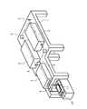
光学系4の内部の光路は図5のように示される。光学系4に入射したレーザー光は、シリンドリカル凹レンズA、シリンドリカル凸レンズB、横方向のフライアイレンズC、縦方向のフライアイレンズDを通過する。シリンドリカル凹レンズA及びシリンドリカル凸レンズBを通過したレーザー光は、後にシリンドリカルレンズHによって集束される方向に拡張される。その後、フライアイレンズC、Dを通過することによってレーザー光はそれまでのガウス分布から矩形分布に変化する。さらに、シリンドリカル凸レンズE、Fを通過してミラーG(図1ではミラー9)を介して、シリンドリカルレンズHによって集束され、試料に照射される。
【0012】
本実施例では、図5の距離X1、X2を固定し、焦点IとミラーGとの距離X3、と距離X4、X5とを調節して、倍率M、焦点距離Fを調整した。すなわち、これらの間には、
M=(X3+X4)/X5、
1/F=1/(X3+X4)+1/X5、
という関係がある。なお、本実施例では光路全長X6は約1.3mであった。
【0013】
このような細長いビームに加工するのは、加工性を向上させるためである。すなわち、短冊状のビームは光学系4を出た後、全反射ミラー9を経て、試料11に照射されるが、試料の幅よりも長いので、結局、試料は1つの方向にのみ移動させてゆけばよい。したがって、試料のステージおよび駆動装置10は構造が簡単で保守も容易である。また、試料をセットする際の位置合わせの操作(アライメント)も容易である。
【0014】
これに対して、正方形に近いビームであれば、それだけで基板全面をカバーすることは不可能であるので、試料を縦方向、横方向というように2次元的に移動させなければならない。しかし、その場合にはステージの駆動装置は複雑になり、また、位置合わせも2次元的に行わなければならないので難しい。特にアライメントを手動でおこなう場合には、その工程での時間のロスが大きく生産性が低下する。なお、これらの装置は防振台等の安定な架台1上に固定される必要がある。
【0015】
試料は、縦100mm、横100〜300mmの各種ガラス基板(例えば、コーニング社製7059番ガラス)を使用した。レーザーはKrFレーザー(波長248nm、パルス幅30nsec)を使用した。
【0016】
ガラス基板上にプラズマCVD法によってアモルファスシリコン膜(半導体膜)を厚さ100Å〜10000Å例えば1000Å(100nm)形成した。これを600℃で48時間アニールして結晶化させた。そして、これを島状にパターニングした。さらに、スパッタ法によって厚さ70nmの酸化珪素膜を形成し、基板全面に燐をドープした。このときはいわゆるイオンドーピング法を使用し、プラズマ源はフォスフィンPH3を使用した。加速電圧は80kVとした。さらに、基板の一部をマスクして、硼素をイオンドーピング法によって注入した。プラズマ源はジボランB2H6で、加速電圧は65kVであった。すなわち、マスクされた箇所には燐が注入され、結果としてN型を示し、マスクされなかった箇所には燐と硼素が注入され、結果としてP型を示す。
【0017】
そして、様々なエネルギー密度、ショット数のレーザーを照射し、レーザー活性化をおこない、シート抵抗を測定して、モフォロジーを光学顕微鏡によって観察した。図2〜図4にその結果を示す。
【0018】
図2は燐イオンを注入したシリコン膜のシート抵抗とレーザー光のエネルギー密度、およびショット数の関係を示す。燐のドーズ量は2×1015cm-2である。レーザーのエネルギー密度が200mJ/cm2以下では、活性化のために多くのショット数を要し、それでもなお10kΩ/□程度の高いシート抵抗しか得られなかったが、200mJ/cm2以上では、1〜10ショットのレーザー照射で充分な活性化がおこなえた。
【0019】
図3は硼素イオン(4×1015cm-2)を注入したシリコン膜(半導体膜)のレーザー活性化を示す。やはり、200mJ/cm2以下のエネルギー密度では活性化は不十分で多くのショット数が必要であった。一方、200〜300mJ/cm2の範囲では、充分に低いシート抵抗が1〜10ショットで得られたが、300mJ/cm2以上のレーザー照射では、かえってシート抵抗が高くなってしまった。特に200mJ/cm2以下の場合とは逆に、ショット数が多いほどシート抵抗が大きくなったが、これは、多数のレーザー照射によって、被膜の均一性が悪化し、結晶の粒界が成長したためである。
【0020】
実際のプロセスでは、レーザーアニールは、P型領域もN型領域も同時におこなう。したがって、レーザーのエネルギー密度を350mJ/cm2に設定したら、N型領域は充分に活性化されるが、P型領域は特性がかえって悪化してしまう。このため、本実施例の条件では、エネルギー密度は200〜300mJ/cm2の範囲、特に250〜300mJ/cm2の範囲が好ましかった。パルス数は1〜100パルスが良い。
【0021】
さて、レーザーアニールによって被膜のモフォロジーに変化が生じることは先に述べた通りであるが、実際にショット数とエネルギー密度とモフォロジーを検討すると、図4のような結果が得られた。ここで、Annealing Pulseとは、レーザーのショット数を意味している。図の黒丸は燐ドープシリコンに於ける表面モフォロジーに変化が現れる点を、白丸は硼素ドープシリコンに於ける変化点をそれぞれ示している。図において右上の領域は膜表面のモフォロジーの悪い(粗い)状態を示し、左下はモフォロジーの良好な(平坦な)状態を示す。燐ドープシリコンの方がレーザーに対して抵抗力が強いことがわかる。この結果から、表面モフォロジーを変化させないようにレーザーアニールをおこなうための条件は、照射されるレーザー光のエネルギー密度をE〔mJ/cm2〕、レーザーパルスのショット数をN〔回〕としたときに、
log10N≦A(E−B)
とであり、不純物が燐の場合には、A=−0.02、B=350であり、不純物が硼素の場合には、A=−0.02、B=300であることが導かれた。
【0022】
モフォロジーが荒れた場合には、部分によってシリコンの特性が著しく悪化するため、ばらつきが著しく大きくなる。実際にモフォロジーの悪い(表面の粗い)シリコン膜ではシート抵抗のばらつきは20%以上であった。ばらつきを下げるためには上記の条件を満たし、かつ、適正なレーザーエネルギー密度を設定しなければならない。
【0023】
例えば、レーザーエネルギー密度を250mJ/cm2とした場合には、レーザーのショット数は10回以下が望ましい。また、レーザーエネルギー密度を280mJ/cm2とした場合には、レーザーのショット数は1〜3回が望ましい。このような条件でレーザーアニールをおこなったときには、シート抵抗のばらつきを10%以下におさえることができた。
【0024】
【発明の効果】
本発明によって最適なレーザーアニールをおこない、よって、ばらつきが少なく信頼性の高い半導体膜を得ることができた。このように本発明は工業上、有益なものと考えられる。
【図面の簡単な説明】
【図1】実施例で使用したレーザーアニール装置の概念図を示す。
【図2】実施例で得られたレーザーアニールされたシリコン膜(燐ドープ、N型)のシート抵抗、レーザーエネルギー密度とショット数の関係を示す。
【図3】実施例で得られたレーザーアニールされたシリコン膜(燐&硼素ドープ、P型)のシート抵抗、レーザーエネルギー密度とショット数の関係を示す。
【図4】実施例で得られたシリコン膜のモフォロジーとレーザーエネルギー密度、ショット数の関係を示す。
【図5】実施例で使用したレーザーアニール装置の光学系の概念図を示す。
【符号の説明】
1 光学架台
2 レーザー装置(発振段)
3 レーザー装置(増幅段)
4 ビーム成形光学系
5〜9 全反射ミラー
10 試料ステージおよび駆動機構
11 試料(ガラス基板)[0001]
BACKGROUND OF THE INVENTION
The present invention relates to a laser annealing method having excellent reliability and mass productivity, small variation, and high yield. In particular, the present invention relates to a laser annealing method for a film that is damaged by ion irradiation, ion implantation, ion doping, or the like and whose crystallinity is significantly impaired.
[0002]
[Prior art]
In recent years, active research has been conducted on lowering the temperature of semiconductor device processes. One reason is that it is necessary to form a semiconductor element on an insulating substrate such as glass. Laser annealing technology is attracting attention as the ultimate low-temperature process.
[0003]
[Problems to be solved by the invention]
Conventionally, however, the laser annealing conditions and the like differ depending on the conditions of each apparatus and coating, and sufficient studies have not been made. As a result, there was a consensus that the laser annealing technology was very varied and could not be put to practical use. The object of the present invention is to present such previously unrecognized conditions, and thus to obtain reproducible results by laser annealing.
[0004]
[Means for Solving the Problems]
The present inventor, in particular, with a film that is amorphous or similar to a crystallinity deteriorated due to damage such as ion irradiation, ion implantation, or ion doping, has a film that does not exhibit sufficient characteristics as a semiconductor. We were looking for optimization of laser annealing conditions for the purpose of activation, but at that time, not only the conditions of the energy of the laser beam, but also the optimal conditions fluctuated depending on the impurities contained and the number of shots of the laser pulse. I discovered that.
[0005]
In the present invention, the film to be activated is a film mainly composed of silicon, germanium, or a group IV element such as silicon-germanium alloy or silicon carbide. These coatings are 100 to 10,000 inches thick. When laser annealing these films, it is known to use a laser having a short wavelength of 400 nm or less in consideration of translucency.
[0006]
For example, it is generally considered that when the energy density of a laser is high, the activation is sufficiently performed and the sheet resistance is lowered. However, in reality, when phosphorus is contained as an impurity, even if such a tendency is clearly obtained, when the impurity is boron, it is deteriorated at high energy. In addition, annealing with a pulsed laser is thought to reduce the variation in results when the number of shots of the pulse increases, but there is also a phenomenon that the morphology of the film deteriorates and the micro variation increases as the number of shots increases. It has become clear that it will occur.
[0007]
This is thought to be due to the large growth of crystal nuclei in the film by repeated laser irradiation. As a result, the distribution is generated with a size of about 0.1 to 1 μm in the coating that has been very homogeneous until then. This was particularly noticeable in the region where the laser energy was large.
[0008]
Further, it was found that the film is not exposed to the atmosphere during laser annealing, but is also covered with a transparent film having a thickness of 3 to 300 nm, typically 10 to 100 nm. . For such a film, silicon oxide or silicon nitride is suitable for the purpose of transmitting laser light. However, a film mainly composed of silicon oxide is usually used because it is necessary to use this film as a gate oxide film. Of course, it may be doped with phosphorus or boron for the purpose of passivating mobile ions. If the group IV coating was not coated with such a transparent coating, the heterogeneity as described above was further accelerated.
[0009]
In order to obtain a flatter (homogeneous) film while satisfying these conditions, the energy density of the irradiated laser light is E [mJ / cm2 ], and the number of shots of the laser pulse is N [times]. And when
log10 N ≦ A (EB)
I found that there is a relationship. A and B differ depending on the impurities contained in the film. When the impurity is phosphorus, A = −0.02 and B = 350, and when the impurity is boron, A = −. 0.02 and B = 300. In the present invention, a transparent substrate may be used instead of the transparent film. In other words, the laser processing method in this case is a pulsed laser having a wavelength of 400 nm or less and a pulse width of 50 nsec or less on a film that is formed on an insulating transparent substrate and is mainly composed of a group IV element and irradiated with high-energy impurity ions. In a laser annealing method in which a semiconductor is activated by irradiating light, the pulsed laser light is applied to the coating through the insulating transparent substrate, and an energy density E [mJ / cm2 ] of the irradiated laser And the number of irradiation pulses N have a relationship of log10 N ≦ −0.02 (E-350). The following examples illustrate the invention in more detail.
[0010]
【Example】
In this embodiment, impurities are introduced into a film (semiconductor film) made of a group IV element to give one of N-type and P-type, and further, impurities are introduced into a part of the film using a mask. The other of the N type and P type is added to the part. FIG. 1 shows a conceptual diagram of a laser annealing apparatus used in this example. The laser light is oscillated by an
[0011]
The optical path inside the
[0012]
In this embodiment, the distances X1 and X2 in FIG. 5 are fixed, the distance X3 between thefocus I and the mirror G, and the distances X4 and X5 are adjusted, and the magnification M and the focal distance F are adjusted. did. That is, between these,
M = (X3 + X4 ) / X5 ,
1 / F = 1 / (X3 + X4 ) + 1 / X5 ,
There is a relationship. In this example, the total optical path length X6 was about 1.3 m.
[0013]
The reason for processing such an elongated beam is to improve processability. That is, the strip-shaped beam exits the
[0014]
On the other hand, if the beam is nearly square, it is impossible to cover the entire surface of the substrate by itself, and the sample must be moved two-dimensionally in the vertical and horizontal directions. However, in this case, the stage driving device becomes complicated, and alignment is also difficult because it must be performed two-dimensionally. In particular, when alignment is performed manually, time loss in the process is large and productivity is lowered. These devices need to be fixed on a
[0015]
As the sample, various glass substrates (for example, No. 7059 glass manufactured by Corning) having a length of 100 mm and a width of 100 to 300 mm were used. The laser used was a KrF laser (wavelength 248 nm, pulse width 30 nsec).
[0016]
An amorphous silicon film (semiconductor film) was formed on a glass substrate by a plasma CVD method to a thickness of 100 to 10,000 mm, for example, 1000 mm (100 nm). This was annealed at 600 ° C. for 48 hours for crystallization. Then, this was patterned into an island shape. Further, a silicon oxide film having a thickness of 70 nm was formed by sputtering, and phosphorus was doped over the entire surface of the substrate. At this time, a so-called ion doping method was used, and phosphine PH3 was used as a plasma source. The acceleration voltage was 80 kV. Further, a part of the substrate was masked, and boron was implanted by an ion doping method. The plasma source was diborane B2 H6 and the acceleration voltage was 65 kV. That is, phosphorus is implanted into the masked portion, resulting in N type, and phosphorous and boron are implanted into the unmasked portion, resulting in P type.
[0017]
Then, lasers with various energy densities and shot numbers were irradiated, laser activation was performed, sheet resistance was measured, and the morphology was observed with an optical microscope. The results are shown in FIGS.
[0018]
FIG. 2 shows the relationship between the sheet resistance of the silicon film implanted with phosphorus ions, the energy density of the laser beam, and the number of shots. The dose of phosphorus is 2 × 1015 cm−2 . When the energy density of the laser was 200 mJ / cm2 or less, a large number of shots were required for activation, and yet only a high sheet resistance of about 10 kΩ / □ was obtained, but at 200 mJ / cm2 or more, 1 Sufficient activation was possible with 10 to 10 shots of laser irradiation.
[0019]
FIG. 3 shows laser activation of a silicon film (semiconductor film) implanted with boron ions (4 × 1015 cm−2 ). Again, activation was insufficient at an energy density of 200 mJ / cm2 or less, and a large number of shots were required. On the other hand, in a range of 200~300mJ / cm2, but sufficiently low sheet resistance was obtained in 10 shots, the 300 mJ / cm2 or more laser irradiation, had rather the sheet resistance becomes higher. In particular, contrary to the case of 200 mJ / cm2 or less, the sheet resistance increases as the number of shots increases. This is because the uniformity of the film deteriorates and the crystal grain boundaries grow due to the multiple laser irradiations. It is.
[0020]
In an actual process, laser annealing is performed simultaneously for both the P-type region and the N-type region. Therefore, when the energy density of the laser is set to 350 mJ / cm2 , the N-type region is sufficiently activated, but the P-type region is deteriorated on the contrary. Therefore, the conditions of this example, the energy density in the range of 200~300mJ / cm2, is particularly from 250~300mJ / cm2 was preferred. The number of pulses is preferably 1 to 100 pulses.
[0021]
As described above, changes in the morphology of the film by laser annealing are as described above. When the number of shots, energy density, and morphology were actually examined, the results shown in FIG. 4 were obtained. Here, Annealing Pulse means the number of laser shots. The black circles in the figure indicate points where changes occur in the surface morphology of phosphorus-doped silicon, and the white circles indicate points of change in boron-doped silicon. In the figure, the upper right region shows a bad (coarse) state of the film surface morphology, and the lower left shows a good (flat) state of the morphology. It can be seen that phosphorus-doped silicon is stronger in resistance to the laser. From this result, the conditions for performing laser annealing so as not to change the surface morphology are as follows: the energy density of the irradiated laser light is E [mJ / cm2 ], and the number of shots of the laser pulse is N [times] In addition,
log10 N ≦ A (EB)
When the impurity is phosphorus, A = −0.02 and B = 350, and when the impurity is boron, A = −0.02 and B = 300. .
[0022]
When the morphology is rough, the characteristics of silicon are remarkably deteriorated depending on the portion, so that the variation becomes remarkably large. In practice, the variation in sheet resistance was 20% or more in a silicon film having a bad morphology (rough surface). In order to reduce the variation, the above conditions must be satisfied and an appropriate laser energy density must be set.
[0023]
For example, when the laser energy density is 250 mJ / cm2 , the number of laser shots is desirably 10 times or less. When the laser energy density is 280 mJ / cm2 , the number of laser shots is desirably 1 to 3 times. When laser annealing was performed under such conditions, variation in sheet resistance could be suppressed to 10% or less.
[0024]
【The invention's effect】
According to the present invention, optimum laser annealing was performed, and thus a highly reliable semiconductor film with little variation was obtained. Thus, the present invention is considered industrially useful.
[Brief description of the drawings]
FIG. 1 is a conceptual diagram of a laser annealing apparatus used in Examples.
FIG. 2 shows the relationship between the sheet resistance, laser energy density, and shot number of a laser-annealed silicon film (phosphorus-doped, N-type) obtained in the example.
FIG. 3 shows the relationship between the sheet resistance, laser energy density and shot number of a laser-annealed silicon film (phosphorus & boron doped, P-type) obtained in the example.
FIG. 4 shows the relationship between the morphology of the silicon film obtained in the example, the laser energy density, and the number of shots.
FIG. 5 is a conceptual diagram of an optical system of a laser annealing apparatus used in Examples.
[Explanation of symbols]
1
3 Laser equipment (amplification stage)
4 Beam shaping
Claims (4)
Translated fromJapanese発振器からレーザー光を発振させ、一組のシリンドリカル凹レンズとシリンドリカル凸レンズ、第1及び第2のフライアイレンズ、第1及び第2のシリンドリカル凸レンズの順に該レーザー光を通して、該レーザー光の断面を前記ガラス基板の横の長さよりも長くなるように第1の方向に拡張させると共に、焦点を有するレーザー光に加工した後、
前記レーザー光の焦点より前記ガラス基板に近い位置に配設されたシリンドリカルレンズにより、前記レーザー光の断面を前記第1の方向と直交する第2の方向に集束させ、
前記半導体膜に前記集束したレーザー光を照射する際、前記ガラス基板を前記第2の方向に移動させる方法であって、
前記一組のシリンドリカル凹レンズとシリンドリカル凸レンズによって前記レーザー光の断面は前記第2の方向に拡張され、その後前記第1及び第2のフライアイレンズによって前記レーザー光の断面における前記第1の方向及び前記第2の方向のエネルギー分布は前記半導体膜において矩形分布となることを特徴とする半導体膜作製方法。Forming a semiconductor film on a glass substrate having a predetermined vertical and horizontal length;
A laser beam is oscillated from an oscillator, and apair of cylindrical concave lens and cylindrical convex lens, first and second fly-eye lenses, first and second cylindrical convex lenses are passed through the laser beamin this order , and the cross section of the laser beam is After extending in the first direction to be longer than the horizontal length of the glass substrate, and processing into a laser beam having a focus,
By a cylindrical lens disposed at a position closer to the glass substrate than the focal point of the laser light, the cross section of the laser light is focused in a second direction orthogonal to the first direction,
A method of moving the glass substrate in the second direction when irradiating the focused laser beam on the semiconductor film;
The cross section of the laser beam is expanded in the second direction by the pair of cylindrical concave lens and the cylindrical convex lens, and then the first direction and the cross section of the laser beam bythe first and second fly-eye lenses . The semiconductor film manufacturing method, wherein the energy distribution in the second direction is a rectangular distribution in the semiconductor film.
発振器からレーザー光を発振させ、一組のシリンドリカル凹レンズとシリンドリカル凸レンズ、第1及び第2のフライアイレンズ、第1及び第2のシリンドリカル凸レンズの順に該レーザー光を通して、該レーザー光の断面を前記ガラス基板の横の長さよりも長くなるように第1の方向に拡張させると共に、焦点を有するレーザー光に加工した後、
前記レーザー光の焦点より前記ガラス基板に近い位置に配設されたシリンドリカルレンズにより、前記レーザー光の断面を前記第1の方向と直交する第2の方向に集束させ、
前記半導体膜に前記集束したレーザー光を照射する際、前記ガラス基板を前記第2の方向に移動させる方法であって、
前記一組のシリンドリカル凹レンズとシリンドリカル凸レンズによって前記レーザー光の断面は前記第2の方向に拡張され、その後前記第1及び第2のフライアイレンズによって前記レーザー光の断面における前記第1の方向及び前記第2の方向のエネルギー分布は前記半導体膜において矩形分布となり、
前記シリンドリカルレンズの倍率Mは、M=(前記焦点から前記シリンドリカルレンズまでの光路長)/(前記シリンドリカルレンズと前記半導体膜との距離)であることを特徴とする半導体膜作製方法。Forming a semiconductor film on a glass substrate having a predetermined vertical and horizontal length;
A laser beam is oscillated from an oscillator, and apair of cylindrical concave lens and cylindrical convex lens, first and second fly-eye lenses, first and second cylindrical convex lenses are passed through the laser beamin this order , and the cross section of the laser beam is After extending in the first direction to be longer than the horizontal length of the glass substrate, and processing into a laser beam having a focus,
By a cylindrical lens disposed at a position closer to the glass substrate than the focal point of the laser light, the cross section of the laser light is focused in a second direction orthogonal to the first direction,
A method of moving the glass substrate in the second direction when irradiating the focused laser beam on the semiconductor film;
The cross section of the laser beam is expanded in the second direction by the pair of cylindrical concave lens and the cylindrical convex lens, and then the first direction and the cross section of the laser beam bythe first and second fly-eye lenses . The energy distribution in the second direction is a rectangular distribution in the semiconductor film,
A magnification M of the cylindrical lens is M = (optical path length from the focal point to the cylindrical lens) / (distance between the cylindrical lens and the semiconductor film).
発振器からレーザー光を発振させ、一組のシリンドリカル凹レンズとシリンドリカル凸レンズ、第1及び第2のフライアイレンズ、第1及び第2のシリンドリカル凸レンズの順に該レーザー光を通して、該レーザー光の断面を前記ガラス基板の横の長さよりも長くなるように第1の方向に拡張させると共に、焦点を有するレーザー光に加工した後、
前記レーザー光の焦点より前記ガラス基板に近い位置に配設されたシリンドリカルレンズにより、前記レーザー光の断面を前記第1の方向と直交する第2の方向に集束させ、
前記半導体膜に前記集束したレーザー光を照射する際、前記ガラス基板を前記第2の方向に移動させる方法であって、
前記一組のシリンドリカル凹レンズとシリンドリカル凸レンズによって前記レーザー光の断面は前記第2の方向に拡張され、その後前記第1及び第2のフライアイレンズによって前記レーザー光の断面における前記第1の方向及び前記第2の方向のエネルギー分布は前記半導体膜において矩形分布となり、
前記シリンドリカルレンズの焦点距離Fは、1/F=1/(前記焦点から前記シリンドリカルレンズまでの光路長)+1/(前記シリンドリカルレンズと前記半導体膜との距離)であることを特徴とする半導体膜作製方法。Forming a semiconductor film on a glass substrate having a predetermined vertical and horizontal length;
A laser beam is oscillated from an oscillator, and apair of cylindrical concave lens and cylindrical convex lens, first and second fly-eye lenses, first and second cylindrical convex lenses are passed through the laser beamin this order , and the cross section of the laser beam is After extending in the first direction to be longer than the horizontal length of the glass substrate, and processing into a laser beam having a focus,
By a cylindrical lens disposed at a position closer to the glass substrate than the focal point of the laser light, the cross section of the laser light is focused in a second direction orthogonal to the first direction,
A method of moving the glass substrate in the second direction when irradiating the focused laser beam on the semiconductor film;
The cross section of the laser beam is expanded in the second direction by the pair of cylindrical concave lens and the cylindrical convex lens, and then the first direction and the cross section of the laser beam bythe first and second fly-eye lenses . The energy distribution in the second direction is a rectangular distribution in the semiconductor film,
The focal length F of the cylindrical lens is 1 / F = 1 / (optical path length from the focal point to the cylindrical lens) + 1 / (distance between the cylindrical lens and the semiconductor film). Manufacturing method.
Priority Applications (1)
| Application Number | Priority Date | Filing Date | Title |
|---|---|---|---|
| JP2000144672AJP3708793B2 (en) | 1992-06-26 | 2000-05-17 | Semiconductor film fabrication method |
Applications Claiming Priority (5)
| Application Number | Priority Date | Filing Date | Title |
|---|---|---|---|
| JP19300592 | 1992-06-26 | ||
| JP4-193005 | 1992-06-26 | ||
| JP25229592 | 1992-08-27 | ||
| JP4-252295 | 1992-08-27 | ||
| JP2000144672AJP3708793B2 (en) | 1992-06-26 | 2000-05-17 | Semiconductor film fabrication method |
Related Parent Applications (1)
| Application Number | Title | Priority Date | Filing Date |
|---|---|---|---|
| JP5173709ADivisionJPH06124913A (en) | 1992-06-26 | 1993-06-21 | Laser processing method |
Publications (2)
| Publication Number | Publication Date |
|---|---|
| JP2001015449A JP2001015449A (en) | 2001-01-19 |
| JP3708793B2true JP3708793B2 (en) | 2005-10-19 |
Family
ID=26507640
Family Applications (10)
| Application Number | Title | Priority Date | Filing Date |
|---|---|---|---|
| JP5173709AWithdrawnJPH06124913A (en) | 1992-06-26 | 1993-06-21 | Laser processing method |
| JP2000144681AWithdrawnJP2000357667A (en) | 1992-06-26 | 2000-05-17 | Laser processing equipment |
| JP2000144655AWithdrawnJP2001023921A (en) | 1992-06-26 | 2000-05-17 | Laser processing equipment |
| JP2000144672AExpired - Fee RelatedJP3708793B2 (en) | 1992-06-26 | 2000-05-17 | Semiconductor film fabrication method |
| JP2000207589AWithdrawnJP2001044131A (en) | 1992-06-26 | 2000-07-07 | Method for manufacturing semiconductor device |
| JP2000237614AWithdrawnJP2001060562A (en) | 1992-06-26 | 2000-08-04 | Method for manufacturing semiconductor device |
| JP2004034893AWithdrawnJP2004186704A (en) | 1992-06-26 | 2004-02-12 | Laser processing equipment |
| JP2007034243AExpired - LifetimeJP4602365B2 (en) | 1992-06-26 | 2007-02-15 | Method for manufacturing semiconductor film |
| JP2009266610AExpired - LifetimeJP4832566B2 (en) | 1992-06-26 | 2009-11-24 | Method for manufacturing semiconductor film |
| JP2011149279AWithdrawnJP2011223027A (en) | 1992-06-26 | 2011-07-05 | Method for manufacturing semiconductor film and electronic apparatus |
Family Applications Before (3)
| Application Number | Title | Priority Date | Filing Date |
|---|---|---|---|
| JP5173709AWithdrawnJPH06124913A (en) | 1992-06-26 | 1993-06-21 | Laser processing method |
| JP2000144681AWithdrawnJP2000357667A (en) | 1992-06-26 | 2000-05-17 | Laser processing equipment |
| JP2000144655AWithdrawnJP2001023921A (en) | 1992-06-26 | 2000-05-17 | Laser processing equipment |
Family Applications After (6)
| Application Number | Title | Priority Date | Filing Date |
|---|---|---|---|
| JP2000207589AWithdrawnJP2001044131A (en) | 1992-06-26 | 2000-07-07 | Method for manufacturing semiconductor device |
| JP2000237614AWithdrawnJP2001060562A (en) | 1992-06-26 | 2000-08-04 | Method for manufacturing semiconductor device |
| JP2004034893AWithdrawnJP2004186704A (en) | 1992-06-26 | 2004-02-12 | Laser processing equipment |
| JP2007034243AExpired - LifetimeJP4602365B2 (en) | 1992-06-26 | 2007-02-15 | Method for manufacturing semiconductor film |
| JP2009266610AExpired - LifetimeJP4832566B2 (en) | 1992-06-26 | 2009-11-24 | Method for manufacturing semiconductor film |
| JP2011149279AWithdrawnJP2011223027A (en) | 1992-06-26 | 2011-07-05 | Method for manufacturing semiconductor film and electronic apparatus |
Country Status (4)
| Country | Link |
|---|---|
| US (7) | US5897799A (en) |
| JP (10) | JPH06124913A (en) |
| KR (6) | KR970005141B1 (en) |
| CN (7) | CN1921069B (en) |
Families Citing this family (114)
| Publication number | Priority date | Publication date | Assignee | Title |
|---|---|---|---|---|
| US6149988A (en)* | 1986-09-26 | 2000-11-21 | Semiconductor Energy Laboratory Co., Ltd. | Method and system of laser processing |
| US6261856B1 (en)* | 1987-09-16 | 2001-07-17 | Semiconductor Energy Laboratory Co., Ltd. | Method and system of laser processing |
| JPH06124913A (en) | 1992-06-26 | 1994-05-06 | Semiconductor Energy Lab Co Ltd | Laser processing method |
| US5643801A (en)* | 1992-11-06 | 1997-07-01 | Semiconductor Energy Laboratory Co., Ltd. | Laser processing method and alignment |
| CN100367461C (en) | 1993-11-05 | 2008-02-06 | 株式会社半导体能源研究所 | Method for manufacturing thin film transistor and electronic device |
| US6897100B2 (en) | 1993-11-05 | 2005-05-24 | Semiconductor Energy Laboratory Co., Ltd. | Method for processing semiconductor device apparatus for processing a semiconductor and apparatus for processing semiconductor device |
| US6723590B1 (en) | 1994-03-09 | 2004-04-20 | Semiconductor Energy Laboratory Co., Ltd. | Method for laser-processing semiconductor device |
| KR100321541B1 (en) | 1994-03-09 | 2002-06-20 | 야마자끼 순페이 | How Active Matrix Display Devices Work |
| US6300176B1 (en)* | 1994-07-22 | 2001-10-09 | Semiconductor Energy Laboratory Co., Ltd. | Laser processing method |
| JP3469337B2 (en) | 1994-12-16 | 2003-11-25 | 株式会社半導体エネルギー研究所 | Method for manufacturing semiconductor device |
| US6130120A (en)* | 1995-01-03 | 2000-10-10 | Goldstar Electron Co., Ltd. | Method and structure for crystallizing a film |
| US5854803A (en) | 1995-01-12 | 1998-12-29 | Semiconductor Energy Laboratory Co., Ltd. | Laser illumination system |
| TW305063B (en)* | 1995-02-02 | 1997-05-11 | Handotai Energy Kenkyusho Kk | |
| TW297138B (en)* | 1995-05-31 | 1997-02-01 | Handotai Energy Kenkyusho Kk | |
| JP2007251196A (en)* | 1995-07-25 | 2007-09-27 | Semiconductor Energy Lab Co Ltd | Manufacturing method of laser beam irradiation device and semiconductor device |
| US6524977B1 (en) | 1995-07-25 | 2003-02-25 | Semiconductor Energy Laboratory Co., Ltd. | Method of laser annealing using linear beam having quasi-trapezoidal energy profile for increased depth of focus |
| JP3917231B2 (en) | 1996-02-06 | 2007-05-23 | 株式会社半導体エネルギー研究所 | Laser irradiation apparatus and laser irradiation method |
| US6599790B1 (en) | 1996-02-15 | 2003-07-29 | Semiconductor Energy Laboratory Co., Ltd | Laser-irradiation method and laser-irradiation device |
| JPH09234579A (en)* | 1996-02-28 | 1997-09-09 | Semiconductor Energy Lab Co Ltd | Laser irradiation device |
| US6759628B1 (en)* | 1996-06-20 | 2004-07-06 | Sony Corporation | Laser annealing apparatus |
| US6040019A (en)* | 1997-02-14 | 2000-03-21 | Advanced Micro Devices, Inc. | Method of selectively annealing damaged doped regions |
| JPH10253916A (en) | 1997-03-10 | 1998-09-25 | Semiconductor Energy Lab Co Ltd | Laser optical device |
| JP3770999B2 (en)* | 1997-04-21 | 2006-04-26 | 株式会社半導体エネルギー研究所 | Laser irradiation apparatus and laser irradiation method |
| JP3462053B2 (en)* | 1997-09-30 | 2003-11-05 | 株式会社半導体エネルギー研究所 | Beam homogenizer, laser irradiation apparatus, laser irradiation method, and semiconductor device |
| JPH11186189A (en)* | 1997-12-17 | 1999-07-09 | Semiconductor Energy Lab Co Ltd | Laser irradiation equipment |
| JP4663047B2 (en)* | 1998-07-13 | 2011-03-30 | 株式会社半導体エネルギー研究所 | Laser irradiation apparatus and method for manufacturing semiconductor device |
| US6246524B1 (en) | 1998-07-13 | 2001-06-12 | Semiconductor Energy Laboratory Co., Ltd. | Beam homogenizer, laser irradiation apparatus, laser irradiation method, and method of manufacturing semiconductor device |
| KR100430231B1 (en)* | 1998-10-02 | 2004-07-19 | 엘지.필립스 엘시디 주식회사 | Laser Annealing Equipment |
| EP1003207B1 (en) | 1998-10-05 | 2016-09-07 | Semiconductor Energy Laboratory Co., Ltd. | Laser irradiation apparatus, laser irradiation method, beam homogenizer, semiconductor device, and method of manufacturing the semiconductor device |
| US6204160B1 (en)* | 1999-02-22 | 2001-03-20 | The United States Of America As Represented By The Secretary Of The Navy | Method for making electrical contacts and junctions in silicon carbide |
| US6393042B1 (en) | 1999-03-08 | 2002-05-21 | Semiconductor Energy Laboratory Co., Ltd. | Beam homogenizer and laser irradiation apparatus |
| JP3562389B2 (en)* | 1999-06-25 | 2004-09-08 | 三菱電機株式会社 | Laser heat treatment equipment |
| JP4827276B2 (en)* | 1999-07-05 | 2011-11-30 | 株式会社半導体エネルギー研究所 | Laser irradiation apparatus, laser irradiation method, and manufacturing method of semiconductor device |
| US7160765B2 (en)* | 1999-08-13 | 2007-01-09 | Semiconductor Energy Laboratory Co., Ltd. | Method for manufacturing a semiconductor device |
| US6567219B1 (en) | 1999-08-13 | 2003-05-20 | Semiconductor Energy Laboratory Co., Ltd. | Laser irradiation apparatus |
| TW473783B (en)* | 1999-08-13 | 2002-01-21 | Semiconductor Energy Lab | Laser apparatus, laser annealing method, and manufacturing method of a semiconductor device |
| TW494444B (en)* | 1999-08-18 | 2002-07-11 | Semiconductor Energy Lab | Laser apparatus and laser annealing method |
| US6548370B1 (en) | 1999-08-18 | 2003-04-15 | Semiconductor Energy Laboratory Co., Ltd. | Method of crystallizing a semiconductor layer by applying laser irradiation that vary in energy to its top and bottom surfaces |
| KR100319455B1 (en) | 1999-12-24 | 2002-01-05 | 오길록 | Optics system for crystallization tool |
| US6872607B2 (en)* | 2000-03-21 | 2005-03-29 | Semiconductor Energy Laboratory Co., Ltd. | Method of manufacturing a semiconductor device |
| US7078321B2 (en) | 2000-06-19 | 2006-07-18 | Semiconductor Energy Laboratory Co., Ltd. | Semiconductor device and method of manufacturing the same |
| TW523791B (en)* | 2000-09-01 | 2003-03-11 | Semiconductor Energy Lab | Method of processing beam, laser irradiation apparatus, and method of manufacturing semiconductor device |
| TW528879B (en)* | 2001-02-22 | 2003-04-21 | Ishikawajima Harima Heavy Ind | Illumination optical system and laser processor having the same |
| JP4921643B2 (en)* | 2001-02-22 | 2012-04-25 | 株式会社Ihi | Illumination optical system and laser processing apparatus including the same |
| US7009140B2 (en)* | 2001-04-18 | 2006-03-07 | Cymer, Inc. | Laser thin film poly-silicon annealing optical system |
| US7061959B2 (en)* | 2001-04-18 | 2006-06-13 | Tcz Gmbh | Laser thin film poly-silicon annealing system |
| TW558861B (en)* | 2001-06-15 | 2003-10-21 | Semiconductor Energy Lab | Laser irradiation stage, laser irradiation optical system, laser irradiation apparatus, laser irradiation method, and method of manufacturing semiconductor device |
| TW552645B (en)* | 2001-08-03 | 2003-09-11 | Semiconductor Energy Lab | Laser irradiating device, laser irradiating method and manufacturing method of semiconductor device |
| US7372630B2 (en)* | 2001-08-17 | 2008-05-13 | Semiconductor Energy Laboratory Co., Ltd. | Laser, irradiation apparatus, laser irradiation method, and method for manufacturing semiconductor device |
| CN2546122Y (en)* | 2001-11-20 | 2003-04-23 | 青岛迪玛特五金工具有限公司 | Laser locating system for hole working machinery |
| US7359762B2 (en) | 2002-04-18 | 2008-04-15 | Black & Decker Inc. | Measurement and alignment device including a display system |
| US6937336B2 (en)* | 2002-08-15 | 2005-08-30 | Black & Decker, Inc. | Optical alignment system for power tool |
| US7369916B2 (en) | 2002-04-18 | 2008-05-06 | Black & Decker Inc. | Drill press |
| US7073268B1 (en) | 2002-04-18 | 2006-07-11 | Black & Decker Inc. | Level apparatus |
| US8004664B2 (en) | 2002-04-18 | 2011-08-23 | Chang Type Industrial Company | Power tool control system |
| US20060076385A1 (en) | 2002-04-18 | 2006-04-13 | Etter Mark A | Power tool control system |
| KR20030095313A (en)* | 2002-06-07 | 2003-12-18 | 후지 샤신 필름 가부시기가이샤 | Laser annealer and laser thin-film forming apparatus |
| US20030233921A1 (en) | 2002-06-19 | 2003-12-25 | Garcia Jaime E. | Cutter with optical alignment system |
| JP2004128421A (en)* | 2002-10-07 | 2004-04-22 | Semiconductor Energy Lab Co Ltd | Laser irradiation method, laser irradiation apparatus, and manufacturing method of semiconductor device |
| US7137327B2 (en) | 2002-10-31 | 2006-11-21 | Black & Decker Inc. | Riving knife assembly for a dual bevel table saw |
| US7160762B2 (en)* | 2002-11-08 | 2007-01-09 | Semiconductor Energy Laboratory Co., Ltd. | Method for manufacturing semiconductor device, semiconductor device, and laser irradiation apparatus |
| JP4429586B2 (en)* | 2002-11-08 | 2010-03-10 | 株式会社半導体エネルギー研究所 | Method for manufacturing semiconductor device |
| SG129265A1 (en)* | 2002-11-29 | 2007-02-26 | Semiconductor Energy Lab | Laser irradiation apparatus, laser irradiation method, and method for manufacturing a semiconductor device |
| US7056810B2 (en)* | 2002-12-18 | 2006-06-06 | Semiconductor Energy Laboratory Co., Ltd. | Method for manufacturing semiconductor apparatus, and semiconductor apparatus and electric appliance |
| JP4515034B2 (en)* | 2003-02-28 | 2010-07-28 | 株式会社半導体エネルギー研究所 | Method for manufacturing semiconductor device |
| DE602004020538D1 (en)* | 2003-02-28 | 2009-05-28 | Semiconductor Energy Lab | Method and device for laser irradiation, and method for the production of semiconductors. |
| US7524712B2 (en)* | 2003-03-07 | 2009-04-28 | Semiconductor Energy Laboratory Co., Ltd. | Method for manufacturing a semiconductor device and laser irradiation method and laser irradiation apparatus |
| US7304005B2 (en)* | 2003-03-17 | 2007-12-04 | Semiconductor Energy Laboratory Co., Ltd. | Laser irradiation apparatus, laser irradiation method, and method for manufacturing a semiconductor device |
| JP4373115B2 (en)* | 2003-04-04 | 2009-11-25 | 株式会社半導体エネルギー研究所 | Method for manufacturing semiconductor device |
| US7290474B2 (en) | 2003-04-29 | 2007-11-06 | Black & Decker Inc. | System for rapidly stopping a spinning table saw blade |
| US7210820B2 (en)* | 2003-05-07 | 2007-05-01 | Resonetics, Inc. | Methods and apparatuses for homogenizing light |
| US7208395B2 (en)* | 2003-06-26 | 2007-04-24 | Semiconductor Energy Laboratory Co., Ltd. | Laser irradiation apparatus, laser irradiation method, and method for manufacturing semiconductor device |
| US7336907B2 (en)* | 2003-10-31 | 2008-02-26 | Texas Instruments Incorporated | Optical assembly having cylindrical lenses and related method of modulating optical signals |
| CN1886872A (en)* | 2003-11-26 | 2006-12-27 | Tcz股份有限公司 | Laser thin film poly-silicon annealing system |
| JP4342429B2 (en)* | 2004-02-09 | 2009-10-14 | 株式会社東芝 | Manufacturing method of semiconductor device |
| US20060146906A1 (en)* | 2004-02-18 | 2006-07-06 | Cymer, Inc. | LLP EUV drive laser |
| JP4579575B2 (en)* | 2004-05-14 | 2010-11-10 | 株式会社半導体エネルギー研究所 | Laser irradiation method and laser irradiation apparatus |
| US7243440B2 (en) | 2004-10-06 | 2007-07-17 | Black & Decker Inc. | Gauge for use with power tools |
| WO2007049525A1 (en) | 2005-10-26 | 2007-05-03 | Semiconductor Energy Laboratory Co., Ltd. | Laser irradiation apparatus and manufacturing method of semiconductor device |
| JP5132119B2 (en)* | 2005-10-26 | 2013-01-30 | 株式会社半導体エネルギー研究所 | Method for manufacturing semiconductor device |
| US7679029B2 (en) | 2005-10-28 | 2010-03-16 | Cymer, Inc. | Systems and methods to shape laser light as a line beam for interaction with a substrate having surface variations |
| US7317179B2 (en) | 2005-10-28 | 2008-01-08 | Cymer, Inc. | Systems and methods to shape laser light as a homogeneous line beam for interaction with a film deposited on a substrate |
| US20070117287A1 (en)* | 2005-11-23 | 2007-05-24 | Semiconductor Energy Laboratory Co., Ltd. | Laser irradiation apparatus |
| WO2007072837A1 (en)* | 2005-12-20 | 2007-06-28 | Semiconductor Energy Laboratory Co., Ltd. | Laser irradiation apparatus and method for manufacturing semiconductor device |
| US7307237B2 (en)* | 2005-12-29 | 2007-12-11 | Honeywell International, Inc. | Hand-held laser welding wand nozzle assembly including laser and feeder extension tips |
| JP2008124149A (en) | 2006-11-09 | 2008-05-29 | Advanced Lcd Technologies Development Center Co Ltd | Optical device, and crystallization equipment |
| DE102007036262A1 (en)* | 2007-08-02 | 2009-02-05 | Robert Bosch Gmbh | Radar sensor for motor vehicles |
| JP2009283807A (en)* | 2008-05-26 | 2009-12-03 | Canon Inc | Structure including nitride semiconductor layer, composite substrate including nitride semiconductor layer, and method for manufacturing them |
| JP5414467B2 (en)* | 2009-11-09 | 2014-02-12 | キヤノン株式会社 | Laser processing method |
| US9069255B2 (en)* | 2009-11-18 | 2015-06-30 | Jim Hennessy | Carrier sheet for a photosensitive printing element |
| JP5302937B2 (en)* | 2010-07-20 | 2013-10-02 | 株式会社イー・エム・ディー | Impurity activation method, semiconductor device manufacturing method |
| CN102169816B (en)* | 2011-03-09 | 2013-02-27 | 清华大学 | Shielding electrode device in ultra-shallow junction deep ultraviolet laser annealing equipment |
| GB2490143B (en)* | 2011-04-20 | 2013-03-13 | Rolls Royce Plc | Method of manufacturing a component |
| DE102011002236A1 (en)* | 2011-04-21 | 2012-10-25 | Dritte Patentportfolio Beteiligungsgesellschaft Mbh & Co.Kg | Process for producing a polycrystalline layer |
| US9769902B1 (en) | 2011-05-09 | 2017-09-19 | The United States Of America As Represented By Secretary Of The Air Force | Laser sensor stimulator |
| US9859348B2 (en) | 2011-10-14 | 2018-01-02 | Diftek Lasers, Inc. | Electronic device and method of making thereof |
| RU2486282C1 (en)* | 2011-11-17 | 2013-06-27 | Федеральное государственное автономное образовательное учреждение высшего профессионального образования "Уральский федеральный университет имени первого Президента России Б.Н. Ельцина" | Method of producing quartz glass implanted with tin ions |
| JP5920662B2 (en)* | 2012-06-05 | 2016-05-18 | 三菱マテリアル株式会社 | Laser processing apparatus and laser processing method |
| JP5920661B2 (en)* | 2012-06-05 | 2016-05-18 | 三菱マテリアル株式会社 | Laser processing apparatus and laser processing method |
| CN104395033B (en)* | 2012-07-04 | 2017-06-23 | 法国圣戈班玻璃厂 | Apparatus and method for laser processing of large area substrates using at least two bridges |
| DE102015000449A1 (en) | 2015-01-15 | 2016-07-21 | Siltectra Gmbh | Solid body distribution by means of material conversion |
| EP2953158A3 (en) | 2014-06-04 | 2016-02-17 | Diftek Lasers, Inc. | Method of fabricating crystalline island on substrate |
| US10121667B2 (en) | 2014-11-12 | 2018-11-06 | President And Fellows Of Harvard College | Creation of hyperdoped semiconductors with concurrent high crystallinity and high sub-bandgap absorptance using nanosecond laser annealing |
| US10930560B2 (en) | 2014-11-27 | 2021-02-23 | Siltectra Gmbh | Laser-based separation method |
| EP4530010A3 (en) | 2014-11-27 | 2025-06-25 | Siltectra GmbH | Solids partitioning using substance conversion |
| FR3035540B1 (en)* | 2015-04-27 | 2017-04-28 | Centre Nat Rech Scient | PRINTING METHOD USING TWO LASERS |
| US10312310B2 (en) | 2016-01-19 | 2019-06-04 | Diftek Lasers, Inc. | OLED display and method of fabrication thereof |
| CN106024604B (en)* | 2016-08-02 | 2018-11-23 | 京东方科技集团股份有限公司 | A kind of laser annealing apparatus |
| JP6870286B2 (en)* | 2016-11-15 | 2021-05-12 | 富士電機株式会社 | Manufacturing method of silicon carbide semiconductor device |
| US9933592B1 (en) | 2017-01-20 | 2018-04-03 | Bae Systems Information And Electronic Systems Integration Inc. | Large aperture, passive optical athermalized beam expander for eye-safe lasers |
| CN106903424B (en)* | 2017-02-20 | 2018-05-29 | 温州大学激光与光电智能制造研究院 | A kind of post-processing approach that optical element mechanical property is improved based on laser blast wave |
| US10411027B2 (en) | 2017-10-19 | 2019-09-10 | Globalfoundries Singapore Pte. Ltd. | Integrated circuits with memory cells and method for producing the same |
| CN109095587B (en)* | 2018-08-28 | 2021-08-03 | 江苏大学 | An optical device based on cavitation degradation of wastewater |
| CN111843713A (en)* | 2020-06-29 | 2020-10-30 | 江苏亚威艾欧斯激光科技有限公司 | Lens processing device and lens array |
Family Cites Families (120)
| Publication number | Priority date | Publication date | Assignee | Title |
|---|---|---|---|---|
| JPS5313976B1 (en)* | 1969-08-04 | 1978-05-13 | ||
| US4151008A (en)* | 1974-11-15 | 1979-04-24 | Spire Corporation | Method involving pulsed light processing of semiconductor devices |
| US4059461A (en)* | 1975-12-10 | 1977-11-22 | Massachusetts Institute Of Technology | Method for improving the crystallinity of semiconductor films by laser beam scanning and the products thereof |
| JPS53135653A (en) | 1977-05-01 | 1978-11-27 | Canon Inc | Photoelectric detecting optical device |
| US4155779A (en)* | 1978-08-21 | 1979-05-22 | Bell Telephone Laboratories, Incorporated | Control techniques for annealing semiconductors |
| JPS5842448B2 (en)* | 1978-08-25 | 1983-09-20 | セイコーエプソン株式会社 | lcd display panel |
| US4309224A (en)* | 1978-10-06 | 1982-01-05 | Tokyo Shibaura Denki Kabushiki Kaisha | Method for manufacturing a semiconductor device |
| US4305640A (en)* | 1978-11-24 | 1981-12-15 | National Research Development Corporation | Laser beam annealing diffuser |
| US4198246A (en)* | 1978-11-27 | 1980-04-15 | Rca Corporation | Pulsed laser irradiation for reducing resistivity of a doped polycrystalline silicon film |
| US4309225A (en)* | 1979-09-13 | 1982-01-05 | Massachusetts Institute Of Technology | Method of crystallizing amorphous material with a moving energy beam |
| US4546009A (en)* | 1979-10-01 | 1985-10-08 | Exxon Research Engineering Co | High-mobility amorphous silicon displaying non-dispersive transport properties |
| JPS5669837A (en)* | 1979-11-12 | 1981-06-11 | Fujitsu Ltd | Manufacture of semiconductor device |
| NL8006339A (en)* | 1979-11-21 | 1981-06-16 | Hitachi Ltd | SEMICONDUCTOR DEVICE AND METHOD FOR THE MANUFACTURE THEREOF. |
| US4370175A (en)* | 1979-12-03 | 1983-01-25 | Bernard B. Katz | Method of annealing implanted semiconductors by lasers |
| JPS5783745A (en) | 1980-11-08 | 1982-05-25 | Chuo Spring Co Ltd | Formation of shock-proof end piece for control cable |
| EP0058548B1 (en)* | 1981-02-16 | 1986-08-06 | Fujitsu Limited | Method of producing mosfet type semiconductor device |
| US4379727A (en)* | 1981-07-08 | 1983-04-12 | International Business Machines Corporation | Method of laser annealing of subsurface ion implanted regions |
| US4431459A (en)* | 1981-07-17 | 1984-02-14 | National Semiconductor Corporation | Fabrication of MOSFETs by laser annealing through anti-reflective coating |
| JPS5823479A (en)* | 1981-08-05 | 1983-02-12 | Fujitsu Ltd | Manufacture of semiconductor device |
| JPS5880852A (en)* | 1981-11-10 | 1983-05-16 | Toshiba Corp | Manufacture of semiconductor device |
| US4484334A (en)* | 1981-11-17 | 1984-11-20 | Allied Corporation | Optical beam concentrator |
| US4475027A (en)* | 1981-11-17 | 1984-10-02 | Allied Corporation | Optical beam homogenizer |
| JPS58127318A (en)* | 1982-01-25 | 1983-07-29 | Nippon Telegr & Teleph Corp <Ntt> | Forming method for single-crystal film on insulating layer |
| US4436557A (en)* | 1982-02-19 | 1984-03-13 | The United States Of America As Represented By The United States Department Of Energy | Modified laser-annealing process for improving the quality of electrical P-N junctions and devices |
| JPS58147708A (en)* | 1982-02-26 | 1983-09-02 | Nippon Kogaku Kk <Nikon> | Optical equipment for illumination |
| JPS58191420A (en)* | 1982-05-04 | 1983-11-08 | Nec Corp | Forming mehtod for single crystal silicon film |
| US4473433A (en)* | 1982-06-18 | 1984-09-25 | At&T Bell Laboratories | Process for producing dielectrically isolated single crystal silicon devices |
| JPS5945089A (en)* | 1982-09-09 | 1984-03-13 | Toshiba Corp | Build-up welding method |
| US4536231A (en)* | 1982-10-19 | 1985-08-20 | Harris Corporation | Polysilicon thin films of improved electrical uniformity |
| US4592799A (en)* | 1983-05-09 | 1986-06-03 | Sony Corporation | Method of recrystallizing a polycrystalline, amorphous or small grain material |
| JPS605508A (en) | 1983-06-24 | 1985-01-12 | Agency Of Ind Science & Technol | Manufacture of semiconductor crystal thin film |
| JPS6014441A (en) | 1983-07-04 | 1985-01-25 | Semiconductor Energy Lab Co Ltd | Semiconductor device manufacturing method |
| US4662708A (en)* | 1983-10-24 | 1987-05-05 | Armco Inc. | Optical scanning system for laser treatment of electrical steel and the like |
| JPS60224282A (en)* | 1984-04-20 | 1985-11-08 | Semiconductor Energy Lab Co Ltd | Manufacture of semiconductor device |
| JPH0693515B2 (en)* | 1984-04-26 | 1994-11-16 | 株式会社半導体エネルギー研究所 | Semiconductor device manufacturing method |
| GB2158843A (en) | 1984-05-14 | 1985-11-20 | Philips Electronic Associated | Method of manufacturing a semiconductor device by molecular beam epitaxy |
| JPH07118443B2 (en)* | 1984-05-18 | 1995-12-18 | ソニー株式会社 | Manufacturing method of semiconductor device |
| JPS60257511A (en)* | 1984-06-04 | 1985-12-19 | Sony Corp | Heat treatment and apparatus therefor |
| JPS6180815A (en)* | 1984-09-27 | 1986-04-24 | Sony Corp | Linear energy beam irradiation equipment |
| US4937459A (en) | 1984-11-16 | 1990-06-26 | Canon Kabushiki Kaisha | Alignment signal detecting device |
| JPS61141174A (en)* | 1984-12-13 | 1986-06-28 | Seiko Epson Corp | Solid state image pickup device |
| JPS61152069A (en) | 1984-12-26 | 1986-07-10 | Hitachi Ltd | Manufacturing method of semiconductor device |
| US4769750A (en)* | 1985-10-18 | 1988-09-06 | Nippon Kogaku K. K. | Illumination optical system |
| US4733944A (en)* | 1986-01-24 | 1988-03-29 | Xmr, Inc. | Optical beam integration system |
| EP0241317B1 (en)* | 1986-04-11 | 1993-03-10 | Canon Kabushiki Kaisha | Process for forming deposited film |
| JPS636501A (en) | 1986-06-27 | 1988-01-12 | Komatsu Ltd | integrator prism |
| JPS6325933A (en)* | 1986-07-17 | 1988-02-03 | Nec Corp | Straining method for silicon substrate |
| JPS6344739A (en)* | 1986-08-12 | 1988-02-25 | Fujitsu Ltd | Manufacture of semiconductor device |
| JPS6384789A (en) | 1986-09-26 | 1988-04-15 | Semiconductor Energy Lab Co Ltd | Light working method |
| US5708252A (en)* | 1986-09-26 | 1998-01-13 | Semiconductor Energy Laboratory Co., Ltd. | Excimer laser scanning system |
| US6149988A (en) | 1986-09-26 | 2000-11-21 | Semiconductor Energy Laboratory Co., Ltd. | Method and system of laser processing |
| JPH0355921Y2 (en)* | 1986-11-11 | 1991-12-13 | ||
| JPH0786647B2 (en) | 1986-12-24 | 1995-09-20 | 株式会社ニコン | Lighting equipment |
| US4943733A (en)* | 1987-05-15 | 1990-07-24 | Nikon Corporation | Projection optical apparatus capable of measurement and compensation of distortion affecting reticle/wafer alignment |
| JP2773117B2 (en) | 1987-06-19 | 1998-07-09 | 株式会社ニコン | Exposure apparatus and exposure method |
| US4773944A (en)* | 1987-09-08 | 1988-09-27 | Energy Conversion Devices, Inc. | Large area, low voltage, high current photovoltaic modules and method of fabricating same |
| JPS6476715A (en)* | 1987-09-17 | 1989-03-22 | Nec Corp | Manufacture of polycrystalline semiconductor thin film |
| JPS6487814A (en) | 1987-09-29 | 1989-03-31 | Matsushita Electric Industrial Co Ltd | Exhaust gas filter |
| JP2540744B2 (en) | 1987-10-08 | 1996-10-09 | 株式会社ニコン | Exposure illumination device using a laser |
| JPH01119020A (en) | 1987-10-30 | 1989-05-11 | Canon Inc | exposure equipment |
| JPH0676312B2 (en)* | 1988-01-19 | 1994-09-28 | 株式会社サンギ | Face wash, hair wash and bath salts |
| JP2623276B2 (en) | 1988-01-22 | 1997-06-25 | 株式会社日立製作所 | Method for manufacturing thin film semiconductor device |
| US5307207A (en)* | 1988-03-16 | 1994-04-26 | Nikon Corporation | Illuminating optical apparatus |
| JPH0831645B2 (en) | 1988-03-16 | 1996-03-27 | 株式会社ニコン | Lighting equipment |
| JPH01239837A (en)* | 1988-03-19 | 1989-09-25 | Nippon Denso Co Ltd | Recrystallization |
| JPH01241862A (en)* | 1988-03-24 | 1989-09-26 | Sony Corp | Manufacture of display device |
| JPH01245993A (en)* | 1988-03-27 | 1989-10-02 | Semiconductor Energy Lab Co Ltd | Thin film working device |
| NL8800953A (en)* | 1988-04-13 | 1989-11-01 | Philips Nv | METHOD FOR MANUFACTURING A SEMICONDUCTOR BODY |
| JP2664723B2 (en) | 1988-05-11 | 1997-10-22 | 富士通株式会社 | Laser annealing equipment |
| JPH01286478A (en) | 1988-05-13 | 1989-11-17 | Hitachi Ltd | Beam uniformizing optical system and manufacture thereof |
| JP2653099B2 (en) | 1988-05-17 | 1997-09-10 | セイコーエプソン株式会社 | Active matrix panel, projection display and viewfinder |
| JPH0220681A (en)* | 1988-07-05 | 1990-01-24 | Fujitsu Ltd | How to focus the laser beam |
| JPH0251224A (en) | 1988-08-15 | 1990-02-21 | Tokyo Electron Ltd | Method for implanting impurity |
| JP2632558B2 (en)* | 1988-09-08 | 1997-07-23 | 株式会社日立製作所 | Laser beam irradiation device and irradiation method |
| US5180690A (en)* | 1988-12-14 | 1993-01-19 | Energy Conversion Devices, Inc. | Method of forming a layer of doped crystalline semiconductor alloy material |
| JP2679319B2 (en)* | 1988-12-22 | 1997-11-19 | 株式会社ニコン | Illumination device, exposure apparatus including the same, and exposure method |
| US5253110A (en) | 1988-12-22 | 1993-10-12 | Nikon Corporation | Illumination optical arrangement |
| JPH02187294A (en)* | 1989-01-13 | 1990-07-23 | Nec Corp | Laser beam shaping apparatus |
| JP2535610B2 (en)* | 1989-02-22 | 1996-09-18 | 株式会社半導体エネルギー研究所 | Method of manufacturing thin film transistor |
| JPH02255292A (en)* | 1989-03-28 | 1990-10-16 | Fuji Electric Co Ltd | Laser processing device |
| US5225924A (en)* | 1989-04-07 | 1993-07-06 | Dainippon Screen Mfg. Co., Ltd. | Optical beam scanning system |
| JP3190653B2 (en)* | 1989-05-09 | 2001-07-23 | ソニー株式会社 | Annealing method and annealing device |
| US5272361A (en)* | 1989-06-30 | 1993-12-21 | Semiconductor Energy Laboratory Co., Ltd. | Field effect semiconductor device with immunity to hot carrier effects |
| US5089802A (en)* | 1989-08-28 | 1992-02-18 | Semiconductor Energy Laboratory Co., Ltd. | Diamond thermistor and manufacturing method for the same |
| JPH03132012A (en)* | 1989-10-18 | 1991-06-05 | Nikon Corp | semiconductor exposure equipment |
| US4997250A (en)* | 1989-11-17 | 1991-03-05 | General Electric Company | Fiber output coupler with beam shaping optics for laser materials processing system |
| JPH03159119A (en)* | 1989-11-17 | 1991-07-09 | Hitachi Ltd | Manufacturing method of semiconductor device |
| US5232674A (en)* | 1989-12-20 | 1993-08-03 | Fujitsu Limited | Method of improving surface morphology of laser irradiated surface |
| JP3033120B2 (en)* | 1990-04-02 | 2000-04-17 | セイコーエプソン株式会社 | Manufacturing method of semiconductor thin film |
| JPH0411226A (en) | 1990-04-27 | 1992-01-16 | Seiko Epson Corp | Manufacture of display device |
| JP2657957B2 (en)* | 1990-04-27 | 1997-09-30 | キヤノン株式会社 | Projection device and light irradiation method |
| US5095386A (en)* | 1990-05-01 | 1992-03-10 | Charles Lescrenier | Optical system for generating lines of light using crossed cylindrical lenses |
| DE69127395T2 (en)* | 1990-05-11 | 1998-01-02 | Asahi Glass Co Ltd | Method of manufacturing a thin film transistor with polycrystalline semiconductor |
| JP2700277B2 (en)* | 1990-06-01 | 1998-01-19 | 株式会社半導体エネルギー研究所 | Method for manufacturing thin film transistor |
| JP3248109B2 (en) | 1990-11-02 | 2002-01-21 | ソニー株式会社 | Step and repeat laser crystallization method and laser beam irradiation method |
| US5236865A (en)* | 1991-01-16 | 1993-08-17 | Micron Technology, Inc. | Method for simultaneously forming silicide and effecting dopant activation on a semiconductor wafer |
| JP3149450B2 (en)* | 1991-04-04 | 2001-03-26 | セイコーエプソン株式会社 | Method and apparatus for manufacturing thin film transistor |
| US5097291A (en)* | 1991-04-22 | 1992-03-17 | Nikon Corporation | Energy amount control device |
| JP3277548B2 (en)* | 1991-05-08 | 2002-04-22 | セイコーエプソン株式会社 | Display board |
| JP3213338B2 (en)* | 1991-05-15 | 2001-10-02 | 株式会社リコー | Manufacturing method of thin film semiconductor device |
| JP3466633B2 (en)* | 1991-06-12 | 2003-11-17 | ソニー株式会社 | Annealing method for polycrystalline semiconductor layer |
| GB9114018D0 (en)* | 1991-06-28 | 1991-08-14 | Philips Electronic Associated | Thin-film transistor manufacture |
| JPH0521339A (en)* | 1991-07-10 | 1993-01-29 | Ricoh Co Ltd | Thin film semiconductor device and its manufacturing method |
| KR100269350B1 (en)* | 1991-11-26 | 2000-10-16 | 구본준 | Manufacturing Method of Thin Film Transistor |
| KR950003235B1 (en)* | 1991-12-30 | 1995-04-06 | 주식회사 금성사 | Structure of semiconductor device |
| US5424244A (en)* | 1992-03-26 | 1995-06-13 | Semiconductor Energy Laboratory Co., Ltd. | Process for laser processing and apparatus for use in the same |
| US5372836A (en)* | 1992-03-27 | 1994-12-13 | Tokyo Electron Limited | Method of forming polycrystalling silicon film in process of manufacturing LCD |
| JP3211377B2 (en)* | 1992-06-17 | 2001-09-25 | ソニー株式会社 | Method for manufacturing semiconductor device |
| JPH06124913A (en) | 1992-06-26 | 1994-05-06 | Semiconductor Energy Lab Co Ltd | Laser processing method |
| CN1088002A (en)* | 1992-11-16 | 1994-06-15 | 东京电子株式会社 | Make the method and apparatus of liquid crystal display substrate and evaluating semiconductor crystals |
| US5403762A (en)* | 1993-06-30 | 1995-04-04 | Semiconductor Energy Laboratory Co., Ltd. | Method of fabricating a TFT |
| JPH06232069A (en)* | 1993-02-04 | 1994-08-19 | Semiconductor Energy Lab Co Ltd | Manufacture of semiconductor device |
| US5366926A (en)* | 1993-06-07 | 1994-11-22 | Xerox Corporation | Low temperature process for laser dehydrogenation and crystallization of amorphous silicon |
| US6300176B1 (en) | 1994-07-22 | 2001-10-09 | Semiconductor Energy Laboratory Co., Ltd. | Laser processing method |
| JP3286518B2 (en) | 1996-01-23 | 2002-05-27 | 三洋電機株式会社 | Electric field strength detection circuit of radio receiver |
| JP3917231B2 (en) | 1996-02-06 | 2007-05-23 | 株式会社半導体エネルギー研究所 | Laser irradiation apparatus and laser irradiation method |
| US5699191A (en) | 1996-10-24 | 1997-12-16 | Xerox Corporation | Narrow-pitch beam homogenizer |
| JP3813269B2 (en) | 1996-11-01 | 2006-08-23 | 株式会社半導体エネルギー研究所 | Laser irradiation system |
| US5986807A (en) | 1997-01-13 | 1999-11-16 | Xerox Corporation | Single binary optical element beam homogenizer |
| JPH10253916A (en) | 1997-03-10 | 1998-09-25 | Semiconductor Energy Lab Co Ltd | Laser optical device |
- 1993
- 1993-06-21JPJP5173709Apatent/JPH06124913A/ennot_activeWithdrawn
- 1993-06-25KRKR1019930011690Apatent/KR970005141B1/ennot_activeExpired - Lifetime
- 1993-06-26CNCN2006101016553Apatent/CN1921069B/ennot_activeExpired - Lifetime
- 1993-06-26CNCN93109565Apatent/CN1076864C/ennot_activeExpired - Lifetime
- 1995
- 1995-07-26CNCN95108719Apatent/CN1108225C/ennot_activeExpired - Lifetime
- 1996
- 1996-06-11USUS08/661,869patent/US5897799A/ennot_activeExpired - Lifetime
- 1996-09-06USUS08/709,108patent/US5858473A/ennot_activeExpired - Lifetime
- 1996-11-21KRKR1019960056010Apatent/KR0169872B1/ennot_activeExpired - Lifetime
- 1997
- 1997-10-23USUS08/956,438patent/US6002101A/ennot_activeExpired - Lifetime
- 1997-10-23USUS08/956,439patent/US5968383A/ennot_activeExpired - Lifetime
- 1997-12-01KRKR1019970064995Apatent/KR100203981B1/ennot_activeExpired - Lifetime
- 1997-12-01KRKR1019970064994Apatent/KR0169945B1/ennot_activeExpired - Lifetime
- 1998
- 1998-11-23USUS09/197,534patent/US6991975B1/ennot_activeExpired - Fee Related
- 1998-11-25KRKR1019980050583Apatent/KR100261853B1/ennot_activeExpired - Lifetime
- 1999
- 1999-07-12USUS09/351,159patent/US6440785B1/ennot_activeExpired - Fee Related
- 1999-12-11CNCNB991267265Apatent/CN1139105C/ennot_activeExpired - Lifetime
- 1999-12-20KRKR1019990059193Apatent/KR100261852B1/ennot_activeExpired - Lifetime
- 2000
- 2000-05-17JPJP2000144681Apatent/JP2000357667A/ennot_activeWithdrawn
- 2000-05-17JPJP2000144655Apatent/JP2001023921A/ennot_activeWithdrawn
- 2000-05-17JPJP2000144672Apatent/JP3708793B2/ennot_activeExpired - Fee Related
- 2000-07-07JPJP2000207589Apatent/JP2001044131A/ennot_activeWithdrawn
- 2000-08-04JPJP2000237614Apatent/JP2001060562A/ennot_activeWithdrawn
- 2001
- 2001-02-10CNCN011045167Apatent/CN1216404C/ennot_activeExpired - Lifetime
- 2001-02-10CNCN01104514Apatent/CN1350322A/enactivePending
- 2001-02-10CNCNB011045159Apatent/CN1214450C/ennot_activeExpired - Lifetime
- 2004
- 2004-02-12JPJP2004034893Apatent/JP2004186704A/ennot_activeWithdrawn
- 2005
- 2005-12-30USUS11/321,641patent/US7985635B2/ennot_activeExpired - Fee Related
- 2007
- 2007-02-15JPJP2007034243Apatent/JP4602365B2/ennot_activeExpired - Lifetime
- 2009
- 2009-11-24JPJP2009266610Apatent/JP4832566B2/ennot_activeExpired - Lifetime
- 2011
- 2011-07-05JPJP2011149279Apatent/JP2011223027A/ennot_activeWithdrawn
Also Published As
Similar Documents
| Publication | Publication Date | Title |
|---|---|---|
| JP3708793B2 (en) | Semiconductor film fabrication method | |
| KR100348342B1 (en) | Laser annealing method and apparatus | |
| US6613619B2 (en) | Semiconductor device and method for producing the same | |
| JP4021135B2 (en) | Laser irradiation apparatus and method for manufacturing semiconductor device | |
| KR100294165B1 (en) | Laser annealing method | |
| TWI238093B (en) | Laser processing apparatus and laser processing method | |
| JPH09129573A (en) | Method and apparatus for laser annealing | |
| JP3587900B2 (en) | Method for manufacturing crystalline silicon film | |
| JP3471485B2 (en) | Optical processing apparatus and optical processing method | |
| JPH10150002A (en) | Method for manufacturing semiconductor film | |
| JPH10150003A (en) | Laser processing equipment | |
| JPH10150001A (en) | Laser processing equipment | |
| JPH04130623A (en) | Manufacturing method of semiconductor device | |
| JP2003100652A (en) | Apparatus and method for irradiation with linear pulsed laser | |
| JP2007251196A (en) | Manufacturing method of laser beam irradiation device and semiconductor device |
Legal Events
| Date | Code | Title | Description |
|---|---|---|---|
| A131 | Notification of reasons for refusal | Free format text:JAPANESE INTERMEDIATE CODE: A131 Effective date:20040818 | |
| A521 | Request for written amendment filed | Free format text:JAPANESE INTERMEDIATE CODE: A523 Effective date:20041013 | |
| A02 | Decision of refusal | Free format text:JAPANESE INTERMEDIATE CODE: A02 Effective date:20050301 | |
| A521 | Request for written amendment filed | Free format text:JAPANESE INTERMEDIATE CODE: A523 Effective date:20050408 | |
| A911 | Transfer to examiner for re-examination before appeal (zenchi) | Free format text:JAPANESE INTERMEDIATE CODE: A911 Effective date:20050531 | |
| TRDD | Decision of grant or rejection written | ||
| A01 | Written decision to grant a patent or to grant a registration (utility model) | Free format text:JAPANESE INTERMEDIATE CODE: A01 Effective date:20050802 | |
| A61 | First payment of annual fees (during grant procedure) | Free format text:JAPANESE INTERMEDIATE CODE: A61 Effective date:20050804 | |
| R150 | Certificate of patent or registration of utility model | Free format text:JAPANESE INTERMEDIATE CODE: R150 | |
| FPAY | Renewal fee payment (event date is renewal date of database) | Free format text:PAYMENT UNTIL: 20080812 Year of fee payment:3 | |
| FPAY | Renewal fee payment (event date is renewal date of database) | Free format text:PAYMENT UNTIL: 20090812 Year of fee payment:4 | |
| FPAY | Renewal fee payment (event date is renewal date of database) | Free format text:PAYMENT UNTIL: 20090812 Year of fee payment:4 | |
| FPAY | Renewal fee payment (event date is renewal date of database) | Free format text:PAYMENT UNTIL: 20090812 Year of fee payment:4 | |
| FPAY | Renewal fee payment (event date is renewal date of database) | Free format text:PAYMENT UNTIL: 20100812 Year of fee payment:5 | |
| FPAY | Renewal fee payment (event date is renewal date of database) | Free format text:PAYMENT UNTIL: 20100812 Year of fee payment:5 | |
| FPAY | Renewal fee payment (event date is renewal date of database) | Free format text:PAYMENT UNTIL: 20110812 Year of fee payment:6 | |
| FPAY | Renewal fee payment (event date is renewal date of database) | Free format text:PAYMENT UNTIL: 20110812 Year of fee payment:6 | |
| FPAY | Renewal fee payment (event date is renewal date of database) | Free format text:PAYMENT UNTIL: 20120812 Year of fee payment:7 | |
| FPAY | Renewal fee payment (event date is renewal date of database) | Free format text:PAYMENT UNTIL: 20120812 Year of fee payment:7 | |
| LAPS | Cancellation because of no payment of annual fees |