JP3708152B2 - Grasping forceps - Google Patents
Grasping forcepsDownload PDFInfo
- Publication number
- JP3708152B2 JP3708152B2JP01247095AJP1247095AJP3708152B2JP 3708152 B2JP3708152 B2JP 3708152B2JP 01247095 AJP01247095 AJP 01247095AJP 1247095 AJP1247095 AJP 1247095AJP 3708152 B2JP3708152 B2JP 3708152B2
- Authority
- JP
- Japan
- Prior art keywords
- pair
- cam
- gripping members
- shaft
- support shaft
- Prior art date
- Legal status (The legal status is an assumption and is not a legal conclusion. Google has not performed a legal analysis and makes no representation as to the accuracy of the status listed.)
- Expired - Fee Related
Links
- 238000003780insertionMethods0.000claimsdescription31
- 230000037431insertionEffects0.000claimsdescription31
- 238000010586diagramMethods0.000description5
- 238000006243chemical reactionMethods0.000description4
- 229910001220stainless steelInorganic materials0.000description4
- 239000010935stainless steelSubstances0.000description4
- 239000007769metal materialSubstances0.000description3
- 230000000694effectsEffects0.000description2
- 239000000463materialSubstances0.000description2
- 239000011347resinSubstances0.000description2
- 229920005989resinPolymers0.000description2
- XLYOFNOQVPJJNP-UHFFFAOYSA-NwaterSubstancesOXLYOFNOQVPJJNP-UHFFFAOYSA-N0.000description2
- 239000012141concentrateSubstances0.000description1
- 238000002674endoscopic surgeryMethods0.000description1
- 238000012976endoscopic surgical procedureMethods0.000description1
- 210000000936intestineAnatomy0.000description1
- 238000002350laparotomyMethods0.000description1
- 239000002184metalSubstances0.000description1
- 210000000056organAnatomy0.000description1
- 229920002492poly(sulfone)Polymers0.000description1
- 229920001296polysiloxanePolymers0.000description1
- 239000004810polytetrafluoroethyleneSubstances0.000description1
- 229920001343polytetrafluoroethylenePolymers0.000description1
- 238000001356surgical procedureMethods0.000description1
- 230000000007visual effectEffects0.000description1
Images


Landscapes
- Surgical Instruments (AREA)
Description
Translated fromJapanese【0001】
【産業上の利用分野】
この発明は、内視鏡下手術の時に使用される把持鉗子に関する。
【0002】
【従来の技術】
近年、開腹をせずに細長い鉗子をトラカールと呼ばれる案内管を介して体腔内に挿入し、内視鏡下で手術を行う、内視鏡下外科手術という術式が行われるようになっている。
【0003】
従来、この種の把持鉗子は、術者が体腔の外で操作する操作部と、トラカールを介して体腔内に挿入される細長い硬性の挿入部と、挿入部の先端に設けられ体腔内で臓器を把持するための開閉可能な鉗子部材とから構成されている。
【0004】
術者は操作部を操作することで挿入部内にその全長に亘って挿通されている操作軸を前後させ、その前後動によって先端の鉗子部材を開閉させることができる。この操作軸の前後動を鉗子部材の開閉動作に変換するための機構としては、例えば特願平5−104633号に示されているようなカム機構等が知られている。
【0005】
【発明が解決しようとする課題】
しかしながら、前記特願平5−104633号に示されているカム機構においては、全閉状態ではカムピンが中心線に対して進行方向と逆側にあり、全開状態ではカムピンが中心線に対して進行方向側にある。
このため、鉗子部材を全閉状態から開方向に旋回運動させるために駆動部材を前進させた場合、カムピンの旋回中心がほぼ中心線上にあることから、カムピンがカム溝の方向に沿って移動を始めて中心線を跨ぐまでの間、カムピンには軸方向に後退する成分の力が作用することになる。
このようなカムピンにかかる後退する成分の力は、駆動部材の動きと相反する方向となる。
【0006】
結果として、カムピンとカム溝が押しつけ合うように動くため、過大な摩擦力が生じ作動がスムーズではなくなる。
このため、術者は緻密さを要求される作業の中で鉗子の動きにも注意を払う必要が生じ、負担を増加させていた。さらに、この動きを繰り返すことによってカムピンおよびカム溝が摩耗し、把持力が低下する虞があった。
【0007】
この発明は、前記事情に着目してなされたもので、その目的とするところは、駆動部材の軸方向の動きをスムーズに鉗子部材の旋回運動に変換し、且つ、繰り返しの使用に対して摩耗による把持力の低下を極力抑えた把持鉗子を提供することにある。
【0008】
【課題を解決するための手段】
この発明は前記目的を達成するために、請求項1は、一対の把持部材と、前記一対の把持部材を回動自在に支持する支持軸と、前記一対の把持部材における前記支持軸より基端側に設けられたカムピンと、前記一対の把持部材を回動操作するために進退自在に備えられた操作軸と、前記操作軸の先端に、前記操作軸の進退方向であって前記支持軸を通る中心線を跨ぐことなく前記一対の把持部材が閉状態から開方向に動くときのカムピンの進行方向側に偏って配置された、前記カムピンを摺動するためのカム溝とを有することを特徴とする把持鉗子にある。
請求項2は、生体内の挿入される挿入部と、前記挿入部の先端部に配設された一対の把持部材と、前記一対の把持部材を回動自在に支持する支持軸と、前記一対の把持部材における前記支持軸より基端側に設けられたカムピンと、前記一対の把持部材を回動操作するために前記挿入部内に進退自在に備えられた操作軸と、前記操作軸の先端に、前記操作軸の進退方向であって前記支持軸を通る中心線を跨ぐことなく前記一対の把持部材が閉状態から開方向に動くときのカムピンの進行方向側に偏って配置された、前記カムピンを摺動するためのカム溝とを有することを特徴とする把持鉗子にある。
【0009】
【作用】
操作軸を前進させると操作軸に設けられたカム軸も同様に前進し、把持部材に設けられたカムピンはカム溝に沿って摺動し、支持軸によって旋回可能に固定された把持部材は開方向に旋回運動する。
このとき、操作軸の進行方向と旋回運動するカムピンの軸方向の動きは同一方向であるため力の伝達はスムーズに行われる。
【0010】
【実施例】
以下、この発明の一実施例を図面に基づいて説明する。
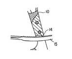
図1は把持鉗子の全体図であり、把持鉗子1は体腔内に挿入される挿入部2と、この挿入部2の近位端に該挿入部2が回転可能に接続された操作部3とから構成されている。把持鉗子1の挿入部2の遠位端にはステンレス等の金属を素材とした2つの把持部材4a、4bからなる把持部5が設けられている。
【0011】
前記挿入部2には、該挿入部2及び前記把持部5を前記操作部3に対して回転させるための回転ノブ6と、図2に示すように、挿入部2の全長に亘って設けられた挿入部2の内腔7に連通し、該内腔7を通して先端に送水するための送水口金8と通常時は体腔内の気体が該内腔7を通って体外に抜けることのないよう気密を保つためのキャップ9とが設けられている。
【0012】
前記操作部3は固定ハンドル10と、可動ハンドル11と、この2つのハンドルを旋回可能に連結する支点ピン12とからなり、前記固定ハンドル10の後端には体腔内の気密を保つためのシリコン等の柔軟性のある素材からなるゴムキャップ13が取り付けられている。
【0013】
また、前記可動ハンドル11には、図3に示すように、固定ハンドル10に設けられた突起部材14に係合し、可動ハンドル11を任意の位置で係止させるためのステンレス等の金属材料からなるラチェット15が旋回可能で、且つ、可動ハンドル11に取り付けられた弾性部材16によって突起部材14に付勢された状態で取り付けられている。
【0014】
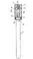
図4〜図8は、前記把持鉗子1の挿入部2の先端部を示す。挿入部2はステンレス鋼等の金属材料もしくは、ポリサルホン等の樹脂からなる中空の管状シース17と、管状シース17の先端部に設けられたステンレス等の金属材料からなる先端カバー18及びPTFE等の樹脂材料からなる絶縁チューブ19から構成されている。
【0015】
前記挿入部2内には前記操作部3の運動を前記把持部5に伝達するための手段である操作軸24が前記挿入部2の内腔7を進退可能なように設置されている。さらに、操作軸24の近位端には前記操作部3に設けられた作動溝23に係合し、該作動溝23内を摺動可能なように球状をなした、前記可動ハンドル11の旋回運動を軸方向の直線運動に変換するための変換部材22が、遠位端には前記把持部5を駆動させるための駆動部材27がそれぞれ設けられている。
【0016】
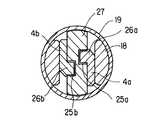
前記把持部5を構成する把持部材4a,4bには近位端側に該把持部材4a,4bが閉状態から開方向に移動するとき中心軸から遠ざかる方向に平行移動できるよう配置された長円形のスリット20a,20bが穿設されている。そして、このスリット20a,20bに係合する支持軸21によって前記先端カバー18が取り付けられている。さらに、前記把持部材4a,4bには前記駆動部材27に設けられたカム溝25a,25bに係合、摺動可能に設けられたカムピン26a,26bが設けられ、開閉機構が構成されている。
【0017】
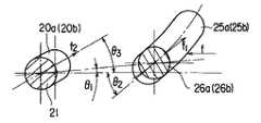
なお、図9に示すように前記支持軸21と前記カムピン26a,26bのなす角度θ1 、前記カム溝25a,25b、スリット20a,20bの中心軸に対する接線方向の角度をθ2 、θ3 、該カム溝25a,25bの接線方向に働く力f1 、及びスリット20a,20bの接線方向に働く力
f2 は操作軸24の遠位端方向にかかっている荷重をfとすれば
f1 =fcosθ2
となり、スリット20a,20bの接線方向に働く力f2 は
f2 =fcosθ1 ・cos(θ3 −θ1 )
となり、該カム溝25及びスリット20a,20bは
f1 <f2
すなわち、
cosθ2 <cosθ1 ・cos(θ3 −θ1 )
を、さらには図10において、図9と同様に操作軸24の近位端方向にかかっている荷重をF、カム溝及びスリットの各接線方向に働く力をF1、F2、各角度をθ4 、θ5 、θ6 、としたときに、
F1>F2
すなわち、
cosθ5 >cosθ4 ・cos(θ6 −θ4 )
を満たすようその形状、及び位置が決められている。
【0018】
なお、上記条件をより確実にするために該カム溝25a,25bの形状は図11に示すように異なる中心線28、29に関する溝から構成されることも可能である。
【0019】
さらに、前記カムピン26a,26bの挿入軸方向に関する動きが常に前記操作軸24と同一方向となるよう前記カム溝25a,25bが前記支持軸21を通る挿入軸方向の中心線を跨ぐことがなく中心線に対して前記カムピン26a,26bの進行方向に偏って配置されている。
【0020】
また、前記把持部材4a,4bはその近位端側が体腔内へトラカール(特に図示せず)を介して挿脱される場合、該トラカールに引っかかることがないよう滑らかな曲線形状をしていると同時に、管状組織31(腸など)が確実に閉塞できるよう十分な長さ(50mm以上)であり、かつ視野をなるべく妨げることがないよう強度の許す範囲で薄く加工され、その把持面30は臓器を傷つけることがないよう鋭利になることを避けた形状となっている。
【0021】
次に、前述のように構成された把持鉗子1の作用について説明する。
図12〜15に示すように、把持鉗子1は、術者が可動ハンドル11を固定ハンドル10に対して開方向に旋回させると、操作軸24の遠位端の変換部材22が可動ハンドル11に設けられている作動溝23内を摺動し、結果的に挿入方向に前進する。
【0022】
操作軸24の前進は駆動部材27によって把持部材4a,4bの平行移動もしくは旋回運動に変換されるが、カム溝25a,25bとスリット20a,20bの関係からスリット20a,20bの接線方向に働く力はカムピン26a,26bの移動方向に働く力に比べ大きいため、把持部材4a,4bはスリット20a,20bの摺動による平行移動がまず行われ、平行移動が完了してから把持部材4a,4bに設けられたカムピン26a,26bがカム溝25a,25bに沿って摺動するようになり結果的に前記支持軸21を中心として開方向に旋回運動が行われるようになる。
【0023】
逆に術者が可動ハンドル11を固定ハンドル10に対して閉方向に旋回させると、操作軸24の遠位端の変換部材22が可動ハンドル11に設けられている作動溝23内を摺動し、結果的に挿入軸方向に後退する。
【0024】
操作軸24の後退は前進のときと同様に駆動部材27によって把持部材4a,4bの平行移動もしくは旋回運動に変換されるが、カム溝25a,25bとスリット20a,20bの関係からスリット20a,20bの接線方向に働く力はカムピン26a,26bの移動方向に働く力に比べ小さいため、まず、把持部材4a,4bに設けられたカムピン26a,26bがカム溝25a,25bに沿って摺動するようになり結果的に前記支持軸21を中心として開方向に旋回運動が行われる。
【0025】
把持部材4a,4bの閉動作がある程度進み、把持面同士が図13のように平行になってから更に操作部3によって操作軸24を後退させると、把持部材4a,4bはスリット20a,20bの摺動によって管状組織31を圧縮するよう平行移動が行われるようになり、管状組織31が閉塞される。
【0026】
前記把持部材4a,4bの開閉動作は、例えば、図15に示すように把持部材4a,4bを開方向に動かすために駆動部材27を遠位方向(図中32の方向)に動かした場合、カムピン26a,26bは常に旋回中心を通る軸方向の中心線Sに対し、進行方向側に偏って配置されているため、その旋回運動中の軸方向の動きは前記駆動部材27と同一(図中33の方向)方向となる。
【0027】
このカムピン26a,26bと駆動部材27の軸方向の動きは閉動作に於いても開動作と同様に同一方向になる。
以上に説明したように本実施例による把持鉗子1は、その閉動作において旋回運動の後に平行移動するため、把持部材4a,4bの把持面が平行になったときの把持面間の距離は唯一に決まるわけではなく、把持しようとする管状組織の肉厚合わせてその幅を選択することが可能することが可能である。
【0028】
つまり、本実施例による把持鉗子1は管状組織31を部位による肉厚に左右されることなく閉塞することが可能となる。
また、カム溝25a,25b及びカムピン26a,26bが常に同一方向に移動するよう構成されているため、操作軸24から把持部材4a,4bにスムーズに力が伝達さると同時に、カム溝25a,25bとカムピン26a,26b間で互いに押し合うことがないため摩擦力が小さく摩耗が押さえられる。
【0029】
なお、本実施例は図に示したものに限定されるものではなく、例えば、本実施例における把持部5が可動部材と固定部材とからなる片開きのものでもよい。
前記実施態様によれば、次のような構成が得られる。
(付記1)生体内に挿入される挿入部の先端に支持軸を介して回動自在に支持された把持部材を開閉駆動する開閉機構を、カム溝とこのカム溝に係合するカムピンとで構成した把持鉗子において、前記カム溝が前記支持軸を通る軸方向の中心線を跨ぐことなく、前記鉗子部材が開方向に動くときのカムピンの進行方向に偏って配置されていることを特徴とする把持鉗子。
(付記2)前記カム溝は、挿入部内を進退する駆動部材の両側面に背合わせ状態に設けられていることを特徴とする付記1記載の把持鉗子。
(付記3)前記カムピンは、一対の鉗子部材の基端部に突設され、カム溝に摺動自在に係合していることを特徴とする付記1記載の把持鉗子。
(付記4)内腔を有する挿入部と、この挿入部の内腔に進退自在に挿入された操作軸と、前記挿入部の遠位端に開閉自在に設けられ前記操作軸の遠位端と開閉機構を介して連結された一対の把持部材と、前記挿入部の近位端に設けられ前記操作軸の近位端と連結された操作部とからなる把持鉗子において、前記開閉機構を、カム溝とこのカム溝に係合するカムピンとで構成し、前記カム溝が前記支持軸を通る軸方向の中心線に跨ぐことなく、前記鉗子部材が開方向に動くときのカムピンの進行方向に偏って配置されていることを特徴とする把持鉗子。
(付記5)前記操作部は、固定ハンドルと、可動ハンドルとからなり、可動ハンドルを固定ハンドルに対して開方向に旋回させることにより、操作軸を前進させ、開閉機構を介して一対の把持部材を開放することを特徴とする付記4記載の把持鉗子。
(付記6)前記操作部は、作動溝を有し、操作軸には前記作動溝内を摺動可能なように球状をなした変換部材が設けられ、可動ハンドルの旋回運動を軸方向の直線運動に変換させることを特徴とする付記4記載の把持鉗子。
(付記7)前記把持部を構成する把持部材は、近位端側に該把持部材が閉状態から開方向に移動するとき中心軸から遠ざかる方向に平行移動できるよう配置された長円形のスリットを有し、このスリットに係合する支持軸によって開閉自在に支持されていることを特徴とする付記4記載の把持鉗子。
【0030】
【発明の効果】
以上説明したように、この発明によれば、鉗子を全閉状態から開こうとするとき、駆動部材の動きは先端の鉗子部材にスムーズに伝達されるため、術者は鉗子の動きに対する注意が減るために手術に集中し、円滑に行うことが可能となる。また、カムピンとカム溝との間には生じる摩擦力は低く抑えられるため繰り返しの使用に対する摩耗も少なくなり把持力の低下が抑えられるという効果がある。
【図面の簡単な説明】
【図1】この発明の一実施例に係わる把持鉗子の全体構成を示す側面図。
【図2】図1のA部を拡大して示す縦断側面図。
【図3】図1のB部を拡大して示す縦断側面図。
【図4】同実施例に係わる把持鉗子の一部を断面して示す平面図。
【図5】同実施例に係わる把持鉗子の一部を断面して示す側面図。
【図6】図5のC−C線に沿う断面図。
【図7】図5のD−D線に沿う断面図。
【図8】同実施例に係わる把持鉗子の鉗子部材が開放位置にある状態を示す側面図。
【図9】同実施例に係わる把持鉗子のカム機構の構成を説明する図。
【図10】同実施例に係わる把持鉗子のカム機構の構成を説明する図。
【図11】同実施例に係わる把持鉗子のカム形状を説明する図。
【図12】同実施例に係わる把持鉗子の鉗子部材の閉動作の様子を示す図。
【図13】同実施例に係わる把持鉗子の鉗子部材の閉動作の様子を示す図。
【図14】同実施例に係わる把持鉗子の鉗子部材の閉動作の様子を示す図。
【図15】同実施例に係わる把持鉗子の駆動部の動作の様子を示す図。
【符号の説明】
1…把持鉗子、2…挿入部、3…操作部、4a,4b…把持部材、5…把持部、20a,20b…スリット、21…支持軸、24…操作軸、25a,25b…カム溝、26a,26b…カムピン、27…駆動部材。[0001]
[Industrial application fields]
The present invention relates to a grasping forceps used at the time of endoscopic surgery.
[0002]
[Prior art]
In recent years, an endoscopic surgical procedure has been performed in which an elongated forceps is inserted into a body cavity through a guide tube called trocar without performing laparotomy, and the operation is performed under an endoscope. .
[0003]
Conventionally, this kind of grasping forceps is provided with an operation unit that an operator operates outside the body cavity, an elongated rigid insertion part that is inserted into the body cavity via a trocar, and an organ within the body cavity that is provided at the distal end of the insertion part. It is comprised from the forceps member which can be opened and closed for grasping.
[0004]
The surgeon operates the operation part to move the operation shaft inserted through the entire length of the insertion part back and forth, and to open and close the forceps member at the distal end by moving back and forth. As a mechanism for converting the back-and-forth movement of the operation shaft into the opening / closing operation of the forceps member, for example, a cam mechanism as shown in Japanese Patent Application No. 5-104633 is known.
[0005]
[Problems to be solved by the invention]
However, in the cam mechanism disclosed in Japanese Patent Application No. 5-104633, in the fully closed state, the cam pin ison the opposite side of the traveling directionwith respect to the center line, and in the fully opened state, the cam pin proceeds with respect to the center line. On the direction side.
For this reason, when the drive member is moved forward in order to swivel the forceps member in the open direction from the fully closed state, the cam pin moves along the direction of the cam groove because the pivot center of the cam pin is substantially on the center line. From the first time until the center line is straddled, the force of the component retreating in the axial direction acts on the cam pin.
The force of the backward component applied to the cam pin is in a direction opposite to the movementof the drive member.
[0006]
As a result, since the cam pin and the cam groove move so as to press each other, an excessive frictional force is generated and the operation is not smooth.
For this reason, it is necessary for the operator to pay attention to the movement of the forceps in an operation that requires preciseness, increasing the burden. Furthermore, the cam pin and the cam groove are worn by repeating this movement, and the gripping force may be reduced.
[0007]
The present invention has been made paying attention to the above circumstances, and the object of the present invention is to smoothly convert the axial movement of the driving member into the swiveling movement of the forceps member, and to wear it over repeated use. It is an object of the present invention to provide a grasping forceps that suppresses a decrease in gripping force due to the above as much as possible.
[0008]
[Means for Solving the Problems]
In order to achieve the above object, the present invention providesa pair of gripping members, a support shaft that rotatably supports the pair of gripping members, and a base end of the pair of gripping members from the support shaft. A cam pin provided on the side, an operation shaft provided to be able to advance and retreat to rotate the pair of gripping members, and a forward and backward direction of the operation shaft at the tip of the operation shaft. A cam groove for sliding the cam pin, which is biased toward the advancing direction side of the cam pin when the pair of gripping members move from the closed state to the open direction without straddling the passing center line. It is in the grasping forceps.
According to a second aspect of the present invention, an insertion portion to be inserted into a living body, a pair of gripping members disposed at a distal end portion of the insertion portion, a support shaft that rotatably supports the pair of gripping members, and the pair A cam pin provided on the base end side of the support shaft of the grip member, an operation shaft provided to be able to advance and retreat in the insertion portion for rotating the pair of grip members, and a tip of the operation shaft. The cam pins arranged in a direction toward the advancing direction of the cam pins when the pair of gripping members move from the closed state to the open direction without straddling a center line passing through the support shaft in a forward / backward direction of the operation shaft A gripping forceps having a cam groove for sliding.
[0009]
[Action]
When the operating shaft is advanced, the cam shaft provided on theoperating shaft advances in the same manner, the cam pin provided on thegripping member slides along the cam groove, and thegripping member fixed pivotably by the support shaft is opened. Rotate in the direction.
At this time, since the movement direction of theoperating shaft is the same as the axial movement of the cam pin that performs the turning motion, the force is transmitted smoothly.
[0010]
【Example】
Hereinafter, an embodiment of the present invention will be described with reference to the drawings.
FIG. 1 is an overall view of a grasping forceps. The grasping forceps 1 includes an
[0011]
The
[0012]
The operation unit 3 includes a
[0013]
Further, as shown in FIG. 3, the movable handle 11 is made of a metal material such as stainless steel for engaging with a protruding
[0014]
4 to 8 show the distal end portion of the
[0015]
An
[0016]
The
[0017]
As shown in FIG. 9, the angle .theta.1 formed by the
The force f2 acting in the tangential direction of the
The cam groove 25 and the
That is,
cos θ2 <cos θ1 · cos (θ3-θ1)
Further, in FIG. 10, as in FIG. 9, the load applied in the proximal end direction of the operating
F1> F2
That is,
cos θ5> cos θ4 · cos (θ6−θ4)
The shape and position are determined so as to satisfy the above.
[0018]
In addition, in order to make the said conditions more reliable, the shape of the
[0019]
Further, the
[0020]
Further, when the proximal end side of the
[0021]
Next, the operation of the grasping forceps 1 configured as described above will be described.
As shown in FIGS. 12 to 15, in the grasping forceps 1, when the operator turns the movable handle 11 in the opening direction with respect to the fixed
[0022]
The forward movement of the
[0023]
Conversely, when the operator turns the movable handle 11 in the closing direction with respect to the fixed
[0024]
The backward movement of the operating
[0025]
If the gripping
[0026]
For example, when the driving
[0027]
The axial movements of the cam pins 26a and 26b and the
As described above, the grasping forceps 1 according to the present embodiment moves in parallel after the turning motion in the closing operation, so that the distance between the grasping surfaces when the grasping surfaces of the grasping
[0028]
That is, the grasping forceps 1 according to the present embodiment can close the
In addition, since the
[0029]
Note that the present embodiment is not limited to the one shown in the figure, and for example, the gripping portion 5 in the present embodiment may be a one-sided opening made of a movable member and a fixed member.
According to the embodiment, the following configuration is obtained.
(Supplementary Note 1) An opening / closing mechanism that opens and closes a gripping member that is rotatably supported via a support shaft at the distal end of an insertion portion that is inserted into a living body is composed of a cam groove and a cam pin that engages with the cam groove. In the configured grasping forceps, the cam groove is arranged so as to be biased in the advancing direction of the cam pin when the forceps member moves in the opening direction without straddling the axial center line passing through the support shaft. Grasping forceps.
(Supplementary note 2) The grasping forceps according to Supplementary note 1, wherein the cam groove is provided in a back-to-back state on both side surfaces of a drive member that advances and retreats in the insertion portion.
(Supplementary note 3) The grasping forceps according to Supplementary note 1, wherein the cam pin is provided at a proximal end portion of a pair of forceps members and is slidably engaged with a cam groove.
(Additional remark 4) The insertion part which has a lumen | bore, the operation axis inserted in the lumen of this insertion part so that advancement / retraction was possible, and the distal end of the said operation axis provided at the distal end of the said insertion part so that opening and closing was possible, In a grasping forceps comprising a pair of gripping members connected via an opening / closing mechanism and an operation portion provided at a proximal end of the insertion portion and connected to a proximal end of the operation shaft, the opening / closing mechanism is camped And a cam pin engaged with the cam groove. The cam groove does not straddle an axial center line passing through the support shaft, and the cam pin is biased in the advancing direction when the forceps member moves in the opening direction. A grasping forceps characterized by being arranged.
(Additional remark 5) The said operation part consists of a fixed handle and a movable handle, and advances a control axis by turning a movable handle to an opening direction with respect to a fixed handle, and a pair of holding members via an opening / closing mechanism The grasping forceps according to appendix 4, wherein the grasping forceps are released.
(Supplementary Note 6) The operation portion has an operation groove, and the operation shaft is provided with a spherical conversion member so as to be slidable in the operation groove, and the pivoting motion of the movable handle is linearized in the axial direction. The grasping forceps according to appendix 4, wherein the grasping forceps are converted into motion.
(Supplementary Note 7) The gripping member constituting the gripping portion has an oval slit arranged on the proximal end side so that the gripping member can be translated in a direction away from the central axis when the gripping member moves in the opening direction from the closed state. The gripping forceps according to appendix 4, wherein the gripping forceps are supported to be freely opened and closed by a support shaft that engages with the slit.
[0030]
【The invention's effect】
As described above, according to the present invention, when the forceps are to be opened from the fully closed state, the movement of the drive member is smoothly transmitted to the forceps member at the distal end, so that the operator is careful about the movement of the forceps. Therefore, it is possible to concentrate on the surgery and to perform smoothly. In addition, since the frictional force generated between the cam pin and the cam groove can be kept low, there is an effect that wear due to repeated use is reduced and a decrease in gripping force is suppressed.
[Brief description of the drawings]
FIG. 1 is a side view showing the overall configuration of a grasping forceps according to an embodiment of the present invention.
FIG. 2 is an enlarged vertical side view showing a portion A of FIG.
FIG. 3 is an enlarged vertical side view showing a portion B in FIG. 1;
FIG. 4 is a plan view showing a part of the grasping forceps according to the embodiment in section.
FIG. 5 is a side view showing a cross section of a part of the grasping forceps according to the embodiment.
6 is a cross-sectional view taken along line CC in FIG.
7 is a cross-sectional view taken along the line DD of FIG.
FIG. 8 is a side view showing a state where the forceps member of the grasping forceps according to the embodiment is in an open position.
FIG. 9 is a diagram for explaining the configuration of a cam mechanism of a grasping forceps according to the embodiment.
FIG. 10 is a diagram illustrating a configuration of a cam mechanism of a grasping forceps according to the embodiment.
FIG. 11 is a view for explaining the cam shape of the grasping forceps according to the embodiment.
FIG. 12 is a diagram showing a closing operation of the forceps member of the grasping forceps according to the embodiment.
FIG. 13 is a diagram showing a closing operation of the forceps member of the grasping forceps according to the embodiment.
FIG. 14 is a diagram showing a closing operation of the forceps member of the grasping forceps according to the embodiment.
FIG. 15 is a view showing an operation state of a driving unit of the grasping forceps according to the embodiment.
[Explanation of symbols]
DESCRIPTION OF SYMBOLS 1 ... Gripping forceps, 2 ... Insertion part, 3 ... Operation part, 4a, 4b ... Gripping member, 5 ... Gripping part, 20a, 20b ... Slit, 21 ... Support axis, 24 ... Operation axis, 25a, 25b ... Cam groove, 26a, 26b ... cam pins, 27 ... driving members.
Claims (2)
Translated fromJapanese前記一対の把持部材を回動自在に支持する支持軸と、
前記一対の把持部材における前記支持軸より基端側に設けられたカムピンと、
前記一対の把持部材を回動操作するために進退自在に備えられた操作軸と、
前記操作軸の先端に、前記操作軸の進退方向であって前記支持軸を通る中心線を跨ぐことなく前記一対の把持部材が閉状態から開方向に動くときのカムピンの進行方向側に偏って配置された、前記カムピンを摺動するためのカム溝と、
を有することを特徴とする把持鉗子。A pair of gripping members;
A support shaft that rotatably supports the pair of gripping members;
Cam pins provided on the base end side from the support shaft in the pair of gripping members;
An operation shaft provided to be able to advance and retract to rotate the pair of gripping members;
The leading end of the operating shaft is biased toward the cam pin moving direction when the pair of gripping members move from the closed state to the opening direction without straddling the center line passing through the support shaft in the forward / backward direction of the operating shaft. A cam groove for sliding the cam pin disposed;
Grasping forceps andhaving a.
前記挿入部の先端部に配設された一対の把持部材と、 A pair of gripping members disposed at the distal end of the insertion portion;
前記一対の把持部材を回動自在に支持する支持軸と、 A support shaft that rotatably supports the pair of gripping members;
前記一対の把持部材における前記支持軸より基端側に設けられたカムピンと、 Cam pins provided on the base end side from the support shaft in the pair of gripping members;
前記一対の把持部材を回動操作するために前記挿入部内に進退自在に備えられた操作軸と、 An operation shaft provided in the insertion portion so as to freely advance and retract in order to rotate the pair of gripping members;
前記操作軸の先端に、前記操作軸の進退方向であって前記支持軸を通る中心線を跨ぐことなく前記一対の把持部材が閉状態から開方向に動くときのカムピンの進行方向側に偏って配置された、前記カムピンを摺動するためのカム溝と、 The leading end of the operating shaft is biased toward the cam pin traveling direction when the pair of gripping members move from the closed state to the opening direction without straddling the center line passing through the support shaft in the advancing and retreating direction of the operating shaft. A cam groove for sliding the cam pin disposed;
を有することを特徴とする把持鉗子。 A grasping forceps characterized by comprising:
Priority Applications (8)
| Application Number | Priority Date | Filing Date | Title |
|---|---|---|---|
| JP01247095AJP3708152B2 (en) | 1995-01-30 | 1995-01-30 | Grasping forceps |
| AT01126032TATE288706T1 (en) | 1994-07-29 | 1995-07-11 | MEDICAL INSTRUMENT FOR USE IN COMBINATION WITH ENDOSCOPES |
| EP95110854AEP0694289B1 (en) | 1994-07-29 | 1995-07-11 | Medical instrument for use in combination with endoscopes |
| DE69534011TDE69534011T8 (en) | 1994-07-29 | 1995-07-11 | Medical instrument for use in combination with endoscopes |
| AT95110854TATE239425T1 (en) | 1994-07-29 | 1995-07-11 | MEDICAL INSTRUMENT FOR USE IN COMBINATION WITH ENDOSCOPES |
| DE69530642TDE69530642T2 (en) | 1994-07-29 | 1995-07-11 | Medical instrument for use in combination with endoscopes |
| EP01126032AEP1177771B1 (en) | 1994-07-29 | 1995-07-11 | Medical instrument for use in combination with endoscopes |
| US08/907,269US5849022A (en) | 1994-07-29 | 1997-08-06 | Medical instrument for use in combination with endoscopes |
Applications Claiming Priority (1)
| Application Number | Priority Date | Filing Date | Title |
|---|---|---|---|
| JP01247095AJP3708152B2 (en) | 1995-01-30 | 1995-01-30 | Grasping forceps |
Publications (2)
| Publication Number | Publication Date |
|---|---|
| JPH08196540A JPH08196540A (en) | 1996-08-06 |
| JP3708152B2true JP3708152B2 (en) | 2005-10-19 |
Family
ID=11806264
Family Applications (1)
| Application Number | Title | Priority Date | Filing Date |
|---|---|---|---|
| JP01247095AExpired - Fee RelatedJP3708152B2 (en) | 1994-07-29 | 1995-01-30 | Grasping forceps |
Country Status (1)
| Country | Link |
|---|---|
| JP (1) | JP3708152B2 (en) |
Families Citing this family (4)
| Publication number | Priority date | Publication date | Assignee | Title |
|---|---|---|---|---|
| JP4614965B2 (en)* | 2003-11-12 | 2011-01-19 | アプライド メディカル リソーシーズ コーポレイション | Overmold gripping jaw |
| KR100923371B1 (en)* | 2008-03-04 | 2009-10-23 | 김선호 | Tweezers for Suture Knot |
| US8409200B2 (en)* | 2008-09-03 | 2013-04-02 | Ethicon Endo-Surgery, Inc. | Surgical grasping device |
| WO2019116570A1 (en)* | 2017-12-15 | 2019-06-20 | オリンパス株式会社 | Medical grasping instrument |
- 1995
- 1995-01-30JPJP01247095Apatent/JP3708152B2/ennot_activeExpired - Fee Related
Also Published As
| Publication number | Publication date |
|---|---|
| JPH08196540A (en) | 1996-08-06 |
Similar Documents
| Publication | Publication Date | Title |
|---|---|---|
| JP3190029B2 (en) | Endoscope biopsy forceps device | |
| EP2415403B1 (en) | Articulable surgical instrument | |
| US5383888A (en) | Articulating endoscopic surgical apparatus | |
| US5468250A (en) | Endoscopic mechanism with friction maintaining handle | |
| US5860995A (en) | Laparoscopic endoscopic surgical instrument | |
| EP0573817B1 (en) | Disposable biopsy forceps | |
| EP0592243B1 (en) | Rotational endoscopic mechanism with jointed drive mechanism | |
| JP3390041B2 (en) | Forceps | |
| US5797958A (en) | Endoscopic grasping instrument with scissors | |
| US6273860B1 (en) | Biopsy apparatus | |
| US5613977A (en) | Gripping and/or cutting instrument for endoscopic purposes | |
| JP5296274B1 (en) | Endoscopic treatment tool | |
| US9168050B1 (en) | End effector construction | |
| JP4354216B2 (en) | LINKING DEVICE FOR TREATMENT TOOL AND TREATMENT TOOL | |
| US20140188159A1 (en) | Surgical tool | |
| US9271749B2 (en) | System and method for an articulating grasper end-effector | |
| US20090082788A1 (en) | Suture management method and apparatus | |
| JP2012165812A (en) | Treatment tool for flexible endoscope and scissors forceps | |
| JP3708152B2 (en) | Grasping forceps | |
| CN115317080A (en) | Minimally invasive surgical instrument with bending and infinite rotation functions and convenient to operate | |
| JP4402313B2 (en) | Surgical treatment tool and surgical treatment apparatus | |
| US20190374217A1 (en) | Endoscopic needle carrier | |
| CN110051391B (en) | Endoscopic surgical instrument | |
| JP7113087B2 (en) | Endoscopic treatment tool | |
| US20220273325A1 (en) | Surgical tool with reduced actuation force |
Legal Events
| Date | Code | Title | Description |
|---|---|---|---|
| A131 | Notification of reasons for refusal | Free format text:JAPANESE INTERMEDIATE CODE: A131 Effective date:20050315 | |
| A521 | Written amendment | Free format text:JAPANESE INTERMEDIATE CODE: A523 Effective date:20050516 | |
| TRDD | Decision of grant or rejection written | ||
| A01 | Written decision to grant a patent or to grant a registration (utility model) | Free format text:JAPANESE INTERMEDIATE CODE: A01 Effective date:20050726 | |
| A61 | First payment of annual fees (during grant procedure) | Free format text:JAPANESE INTERMEDIATE CODE: A61 Effective date:20050803 | |
| FPAY | Renewal fee payment (event date is renewal date of database) | Free format text:PAYMENT UNTIL: 20090812 Year of fee payment:4 | |
| FPAY | Renewal fee payment (event date is renewal date of database) | Free format text:PAYMENT UNTIL: 20100812 Year of fee payment:5 | |
| FPAY | Renewal fee payment (event date is renewal date of database) | Free format text:PAYMENT UNTIL: 20100812 Year of fee payment:5 | |
| FPAY | Renewal fee payment (event date is renewal date of database) | Free format text:PAYMENT UNTIL: 20110812 Year of fee payment:6 | |
| FPAY | Renewal fee payment (event date is renewal date of database) | Free format text:PAYMENT UNTIL: 20120812 Year of fee payment:7 | |
| LAPS | Cancellation because of no payment of annual fees |