JP3707973B2 - Folding container - Google Patents
Folding containerDownload PDFInfo
- Publication number
- JP3707973B2 JP3707973B2JP31786599AJP31786599AJP3707973B2JP 3707973 B2JP3707973 B2JP 3707973B2JP 31786599 AJP31786599 AJP 31786599AJP 31786599 AJP31786599 AJP 31786599AJP 3707973 B2JP3707973 B2JP 3707973B2
- Authority
- JP
- Japan
- Prior art keywords
- side wall
- long side
- folding container
- wall
- short side
- Prior art date
- Legal status (The legal status is an assumption and is not a legal conclusion. Google has not performed a legal analysis and makes no representation as to the accuracy of the status listed.)
- Expired - Fee Related
Links
- 238000003825pressingMethods0.000claimsdescription30
- 238000003780insertionMethods0.000description22
- 230000037431insertionEffects0.000description22
- 230000008878couplingEffects0.000description11
- 238000010168coupling processMethods0.000description11
- 238000005859coupling reactionMethods0.000description11
- 230000003014reinforcing effectEffects0.000description5
- 230000002093peripheral effectEffects0.000description4
- 229920005989resinPolymers0.000description4
- 239000011347resinSubstances0.000description4
- 238000002372labellingMethods0.000description3
- 238000000465mouldingMethods0.000description3
- 238000007639printingMethods0.000description3
- 230000007423decreaseEffects0.000description2
- 230000000694effectsEffects0.000description2
- 230000002452interceptive effectEffects0.000description2
- 241000257465EchinoideaSpecies0.000description1
- 230000004308accommodationEffects0.000description1
- 238000005452bendingMethods0.000description1
- 230000033228biological regulationEffects0.000description1
- 238000001746injection mouldingMethods0.000description1
- 238000000034methodMethods0.000description1
- 229920003002synthetic resinPolymers0.000description1
- 239000000057synthetic resinSubstances0.000description1
Images


Classifications
- B—PERFORMING OPERATIONS; TRANSPORTING
- B65—CONVEYING; PACKING; STORING; HANDLING THIN OR FILAMENTARY MATERIAL
- B65D—CONTAINERS FOR STORAGE OR TRANSPORT OF ARTICLES OR MATERIALS, e.g. BAGS, BARRELS, BOTTLES, BOXES, CANS, CARTONS, CRATES, DRUMS, JARS, TANKS, HOPPERS, FORWARDING CONTAINERS; ACCESSORIES, CLOSURES, OR FITTINGS THEREFOR; PACKAGING ELEMENTS; PACKAGES
- B65D11/00—Containers having bodies formed by interconnecting or uniting two or more rigid, or substantially rigid, components made wholly or mainly of plastics material
- B65D11/18—Containers having bodies formed by interconnecting or uniting two or more rigid, or substantially rigid, components made wholly or mainly of plastics material collapsible, i.e. with walls hinged together or detachably connected
- B65D11/1833—Containers having bodies formed by interconnecting or uniting two or more rigid, or substantially rigid, components made wholly or mainly of plastics material collapsible, i.e. with walls hinged together or detachably connected whereby all side walls are hingedly connected to the base panel
Landscapes
- Engineering & Computer Science (AREA)
- Mechanical Engineering (AREA)
- Rigid Containers With Two Or More Constituent Elements (AREA)
- Containers And Packaging Bodies Having A Special Means To Remove Contents (AREA)
- Packages (AREA)
Abstract
Description
Translated fromJapanese【0001】
【発明の属する技術分野】
本発明は、底部を囲むように配設された側壁が、底部に重なるように折り畳むことができる折り畳みコンテナーに関するものである。
【0002】
【従来の技術】
従来,一例として、平面形状がほぼ長方形に形成された底部の相対する長辺部に、ヒンジ部を介して連結された長側壁と、同じく上記底部の相対する短辺部に、ヒンジ部を介して連結された短側壁とからなる折り畳みコンテナーが知られており、折り畳み状態においては、底部の上に短側壁が重なるように折り畳まれ、更にその上に、長側壁が折り畳まれており、そして、折り畳まれた状態の長側壁を、底部に対して垂直に立て、次いで、折り畳まれた状態の短側壁を、底部に対して垂直に立てることにより、箱型の折り畳みコンテナーに組み立てられるように構成されている。
【0003】
折り畳みコンテナーが折り畳まれた状態では、一番下に底部が位置し、その上に、重なるように折り畳まれた短側壁が位置し、更にその上に、重なるように折り畳まれた長側壁が位置することになる。このように折り畳んだ状態の折り畳みコンテナーを、積み重ねる場合には、下に位置する折り畳んだ状態の折り畳みコンテナーの長側壁の上に、上に位置する折り畳んだ状態の折り畳みコンテナーの底部が載置されることになる。また、折り畳みコンテナーの長側壁の両方の下部角部(底部側に位置する角部)付近には、ほぼL字状の嵌合土手部が形成されており、折り畳まれた状態の2つの長側壁の4つの角部には、平面形状がほぼL字状の嵌合土手部が位置することになる。そして、折り畳んだ状態の折り畳みコンテナーを積み重ねる際には、下に位置する折り畳んだ状態の折り畳みコンテナーの2つの長側壁の4つの角部に位置する嵌合土手部に、上に位置する折り畳んだ状態の折り畳みコンテナーの底部が嵌合されるように構成されているので、下に位置する折り畳んだ状態の折り畳みコンテナーに対する、上に位置する折り畳んだ状態の折り畳みコンテナーの水平方向の移動が制限されて、多数、積み重ねられた折り畳まれた状態の折り畳みコンテナーが、ふらついて、崩れることがないように、安定して積み重ねられることになる。
【0004】
【発明が解決しようとする課題】
上述したように、従来の折り畳みコンテナーにおいては、多数の折り畳まれた状態の折り畳みコンテナーを、安定した状態で積み重ねるために、折り畳みコンテナーの長側壁の両方の下部角部付近に、嵌合土手部が形成されているが、この嵌合土手部は、組み立てられた状態においては、長側壁から突出しており、従って、長側壁同士が、互いに当接するように、2つの組み立てられた折り畳みコンテナーを並設した場合には、並設された折り畳みコンテナー間に無駄な間隙ができることになり、従って、組み立てられた折り畳みコンテナーの保管スペースが増大し、保管効率が低下するという問題があった。また、嵌合土手部を形成したために、長側壁の厚みが増し、従って、組み立てられた折り畳みコンテナーの外寸に対して、内容積が小さく、組み立てられた折り畳みコンテナーの収容効率が悪いという問題があった。
【0005】
また、従来の折り畳みコンテナーにおいては、組み立てられた状態における、長側壁と短側壁の係合が十分なものでないために、組み立てられた状態の折り畳みコンテナーを積み重ねた際のように、長側壁や短側壁に、上から負荷がかかると、長側壁と短側壁との係合が外れてしまうという問題があった。
【0006】
更に、従来の折り畳みコンテナーにおいては、長側壁や短側壁に、上から負荷がかかると、底部と長側壁及び底部と短側壁とを結合しているヒンジ部に負荷かかかり、ヒンジ部が損傷するという問題があった。
【0007】
更にまた、従来の折り畳みコンテナーにおいては、底部と長側壁及び底部と短側壁とを結合しているヒンジ部の構造に問題があるために、底部、長側壁及び短側壁をヒンジ結合して折り畳みコンテナーを組み立てる折り畳みコンテナーの組み立て作業性が悪いという問題があった。
【0008】
また更に、従来、折り畳みコンテナーに配設されるカード差しは、別途、製造されて、長側壁や短側壁に取り付けるものであるために、カード差しの取り付け作業に、時間と労力を要し、ひいては、折り畳みコンテナーの価格が上昇するという問題があった。
【0009】
本発明の目的は、上述した従来の折り畳みコンテナーが有する課題を解決するとともに、取り扱い性や収容効率の向上した折り畳みコンテナーを提供することにある。
【0010】
【課題を解決するための手段】
本発明は、上述した目的を達成するために、底部を囲むように配設された側壁を、底部に重なるように折り畳むことができるとともに、底部に対して垂直に立てられた側壁が内側に倒れないように、隣り合う側壁が互いに係合し合う係合枠部が側壁に形成されている折り畳みコンテナーにおいて、第1には、底部には、折り畳まれた状態の折り畳みコンテナーの底部が嵌合可能な係止ブロックが形成されており、且つ、側壁には、組み立てられた状態の折り畳みコンテナーの係止ブロックが挿入可能な下方が開放された凹部が形成されているとともに、係合枠部を介して、側壁同士及び側壁と底部が係合し合うようにしたものであり、第2には、相対する一方の側壁には、折り畳んだ際に、上方に突出する係止ブロックが挿入可能な透孔が穿設されているものであり、第3には、側壁の係合枠部に形成された係合突起が、底部に形成された嵌合部の透孔に嵌合されるように構成されているものであり、第4には、底部に対して側壁が垂直に立てられた際に、側壁の下面と底部の上面が、その一部において、面接触するように構成したものであり、第5には、カード差しを構成するカード押さえ条片が、薄肉連結部を介して側壁と一体に形成されているものである。
【0011】
【実施例】
以下に、本発明の実施例について説明するが、本発明の趣旨を越えない限り何ら、本実施例に限定されるものでない。
【0012】
100は、平面形状が長方形状の底部であり、底部100の相対する長辺部101には、後述するヒンジ部を介して長側壁200が連結されており、また、底部100の相対する短辺部102には、同じくヒンジ部を介して短側壁300が連結されている。
【0013】
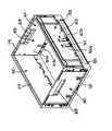
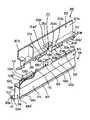
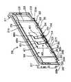
図1に示されているように、箱型に組み立てられた状態の折り畳みコンテナーを折り畳むには、先ず最初に、短側壁300を折り畳みコンテナーの内側に倒して、図2に示されているように、底部100の上に重ねる。次いで、同じく、長側壁200を折り畳みコンテナーの内側に倒して、図3に示されているように、底部100及び短側壁300の上に重ねる。逆に、図3に示されている折り畳まれた状態から、図1に示されているように組み立てるには、底部100及び短側壁300の上に重ねられた状態の長側壁200を垂直に立て、次いで、短側壁300を垂直に立てて、折り畳みコンテナーを箱型に組み立てる。
【0014】
次に、主として、図4〜図7を用いて、底部100について説明する。
【0015】
底部100は、底板103を有しており、底板103の長辺縁には、底部100の長辺部101を構成する、ほぼ逆U字状の二重壁部104が形成されている。二重壁部104は、外壁104aと、内壁104bと、外壁104aの上端と内壁104bの上端を連結する水平壁104cとから構成されており、底板103の裏面103aは、外壁104aの下端104a’より下方に位置しており、底板103の外壁104aの下端104a’より下方に位置している部分が、後述する底部嵌合部100aを構成する。二重壁部104を構成する外壁104aを上方に延長して、横長の端部壁105が形成されており、端部壁105は、長辺部101の両端部を除いて、長辺部101に沿って形成されている。
【0016】
また、二重壁部104を構成する内壁104bの上端からは、ほぼ垂直に上方に延在する板状片106aが延設されており、板状片106aには、板状片106aに対して端部壁105側に配設されたほぼ半円筒状フック106bが連接され、板状片106aとフック106bとにより、ほぼ逆J字状のヒンジ雌部106が構成されている。ヒンジ雌部106は、端部壁105の高さとほぼ同じ高さを有しており、長辺部101に沿って、適当数、形成されている(本実施例においては、ほぼ等間隔に、4個のヒンジ雌部106が形成されている。)。なお、二重壁部104の内部には、外壁104a、内壁104b及び水平壁104cを連結する内部補強リブ107を、適当な間隔で形成することができる。
【0017】
長辺部101の両端部付近に位置するヒンジ雌部106と、該ヒンジ雌部106より中央寄りに位置するヒンジ雌部106との間に位置する、端部壁105と二重壁部104の水平壁104cとで形成される隅部には、外面108aが端部壁105の外面105aとほぼ面一な長辺部側係止ブロック108が形成されている。長辺部側係止ブロック108は、端部壁105を超えて上方に延在する突出部108bを有するとともに、端部壁105の上端とほぼ同じ高さの載置面108cを有する、内側に向いた切り欠き部108dが形成されている。
【0018】
長辺部101の両端部には、二重壁部104の外壁104aと内壁104bを上方に延長することにより形成された、長辺部側係止ブロック108とほぼ同じ高さの端部係止ブロック109が形成されており、端部係止ブロック109には、長辺部側係止ブロック108の載置面108cとほぼ同じ高さを有する載置面109aと、載置面109aより上方に突出した突出部109bが形成されている。突出部109bは、長辺部101に沿って延在する突出部109b’と、該突出部109b’に直角で短辺部102方向に延びる突出部109b”とからなり、平面形状がほぼL字状に形成されている。端部係止ブロック109の外面109cも、端部壁105の外面105aとほぼ面一に形成されている。なお、110は、端部壁105と二重壁部104の水平壁104cとで形成される隅部に、適宜、形成された補強ブロックであり、補強ブロック110の上端は、端部壁105の上端に一致しているが、必要に応じて、補強ブロック110の上端は、端部壁105の上端より下方に位置するように構成することもできる。
【0019】
底部100の短辺部102は、長辺部101より、低く形成されており、短辺部102は、底板103の短辺縁に沿って、ほぼ垂直に上方に延在する垂直壁111を有している。垂直壁111に近接した底板103には、垂直壁111に沿って、所定の間隔で、上述したと同様のヒンジ雌部106が形成されている(本実施例においては、ほぼ等間隔に、4個のヒンジ雌部106が形成されている。)。
【0020】
短辺部102を構成する垂直壁111の両端部を、上方に延長することにより、透孔112aが穿設されたほぼ方形状の嵌合部112が形成されている。嵌合部112の高さは、長辺部101の両端部に形成された端部係止ブロック109より低く、透孔112aには、後述する短側壁300に形成された嵌合突起が嵌合するように構成されている。短辺部102の垂直壁111と底板103とにより形成される隅部には、短辺側係止ブロック113が形成されている。そして、短辺側係止ブロック113の高さは、上述した長辺部側係止ブロック108及び端部係止ブロック109とほぼ同じ高さに形成されており、また、短辺側係止ブロック113には、長辺部側係止ブロック108の載置面108cや端部係止ブロック109の載置面109aとほぼ同じ高さの載置面113aを形成する、内側に向いた切り欠き部113bが形成されている。また、短辺側係止ブロック113の外面113cは、短辺部102を構成する垂直壁111の外面111aとほぼ面一に形成されており、少なくとも、垂直壁111の外面111aを超えて、外側に突出することがないように構成されている。
【0021】
なお、114は、短辺部102の中程に形成された、所定の間隔を置いて配置された一対の水平枠114a、114aと背枠114bとにより、外側が開口された凹部114cが形成された、ロボット等の自動機の爪や、作業者の指等が挿入可能な、引っ掛け部である。引っ掛け部114は、垂直壁111の中程を、引っ掛け部114の幅分だけ分断することにより、形成されている。115は、底部100の長辺部101を構成する二重壁部104の外壁104aに形成された凹部であり、この凹部115に、折り畳みコンテナーに収容された物品の行き先や、物品の種類、個数等の折り畳みコンテナーや収容された物品に関する種々の情報が記載された或いは記憶されたラベルやバーコードや磁気テープ等が貼着されるように構成されている。なお、116は、必要に応じて、底板103の裏面103aに形成された縦横に走る、高さの低い補強リブである。
【0022】
後述するように、短側壁300や長側壁200にカード差しを配設した上に、更に、上述したように、底部100の二重壁部104の外壁104aに、印刷及びラベル貼付用の凹部115が形成されているので、折り畳みコンテナー内に収容されている物品の種類や行き先等の種々の情報の識別が、より容易に、且つ、確実になる。
【0023】
更に、折り畳みコンテナーの大きさが異なると、換言すれば、長側壁200や短側壁300の大きさが異なると、長側壁200や短側壁300に設けられたラベル貼付部やカード差しの位置が大きく異なる場合があるが、折り畳みコンテナーの大きさが異なっても、底部100の位置、特に、その高さは、大きく異なることはない。従って、ベルトコンベヤー等の搬送装置により搬送されている途中で、搬送装置付近に配設された読取機の読み取りセンサーにより、底部100の二重壁部104の外壁104aに形成された印刷及びラベル貼付用の凹部115に、印刷或いは貼付されたラベルを読み取るようにすれば、折り畳みコンテナーの大きさが異なっても、印刷及びラベル貼付用の凹部115の位置は、大きく異なることはないので、読取機による折り畳みコンテナー内に収容されている物品の種類や行き先等の種々の情報の読み取りが、正確に、且つ、確実に行われることになる。従って、ラベル貼付部の位置が異なるために、読み取りが失敗するというようなことが防止できるとともに、折り畳みコンテナーの大きさにより、読取機の読み取りセンサーの位置を変更する必要もない。
【0024】
次に、図2、図5、図6及び図8〜図10を用いて、長側壁2について説明する。
【0025】
長側壁200は、横長の方形状の板状部201と、板状部201の下端から外方向に向かって延在する下部水平枠202を有しており、下部水平枠202の下面には、底部111の長辺部101側に形成されたヒンジ雌部106に対応して、ヒンジ雄部203が形成されている。ヒンジ雄部203は、下部水平枠202の下面に垂下され、板状部201に対して直角な一対の垂直片203aと、一対の垂直片203a間に配設された水平ピン203bとから構成されており、垂直片203aの下部は、半円形部203a’として形成されている。
【0026】
204は、下部水平枠202の下面に形成された、上記の垂直片203aと同様の一対の垂直片204aと垂直片204aを連結する連結壁204bとからなる下部ブロックであり、連結壁204bの下端部は、垂直片204aの半円形部204a’とほぼ同じように彎曲された半円筒部に形成されている。なお、下部ブロック204の下端は、ヒンジ雄部203の垂直片203cの下端と一致しており、下部ブロック204の垂直片204aの半円形部204a’や連結壁204bの半円筒部は、ヒンジ雄部203の垂直片203aの半円形部203a’と、ほぼ同じ半径を有している。
【0027】
ヒンジ雄部203の垂直片203aの端部壁105側の端面203a”及び下部ブロック204の垂直片204aの端部壁105側の端面204a”は、端部壁105のほぼ肉厚分だけ、下部水平枠202より引っ込んでいる。そして、底部100と長側壁200を、上述したヒンジ雌部106とヒンジ雄部203とによりヒンジ結合するとともに、長側壁200を、底部100に対して垂直に立てた際には、ヒンジ雄部203の垂直片203a及び下部ブロック204の垂直片204aの下部水平枠202より引っ込んだ部分に、底部100の端部壁105が入り込み、端部壁105の上端に、長側壁200の下部水平枠202の下面が当接するように構成されている(特に、後述する図14を参照されたい。)。長側壁200に上方から負荷がかかっても、端部壁105の上端に、長側壁200の下部水平枠202の下面が当接するように構成されているので、長側壁200にかかった負荷が、端部壁105の上端と長側壁200の下部水平枠202の下面との当接により、この部分で負担されて、このような負荷が、ヒンジ雌部106とヒンジ雄部203に及ぶようなことが防止でき、従って、ヒンジ雌部106とヒンジ雄部203の損傷やヒンジ結合が外れるようなことが防止できる。
【0028】
板状部201の外面201aには、適宜、垂直リブ205や水平リブ206が、複数、形成されている。折り畳みコンテナーが組み立てられ、長側壁200が、底部100に対して、垂直に立てられた際には、板状部201の内面201bは、底部100の長辺部101を構成する二重壁部104の内壁104bや、ヒンジ雌部106の板状片106aの内面等と、ほぼ面一になるように構成されており、折り畳みコンテナーが組み立てられた状態において、折り畳みコンテナーの長側壁200側の内面に、突出部が形成されないように構成されている。そして、折り畳みコンテナーが組み立てられた状態においては、垂直リブ205や水平リブ206が、底部100の長辺部102を構成する二重壁部104の外壁104aを超えて、外側に突出しないように構成されている。
【0029】
長側壁200の両端部には、板状部201に直交する方向で、且つ、内面201b側に延在する係合枠部207が形成されており、係合枠部207の上部には、上部嵌合透孔207aが穿設されており、上部嵌合透孔207aの下方に穿設された2つの透孔207b、207c間には、水平で、横長の係合突起207dが、係合枠部207の内面207’に突設されている。図10に示されているように、係合突起207dの断面形状は、先端部が先細り状の膨出部207d’と、膨出部207d’から係合枠部207の外面207”に向かって延在する水平部207d”とにより、横向きのほぼ茸状に形成されている。更に、係合突起207dの下方には、係合枠部207を一部切り欠くことにより形成された嵌合凹部207eが形成されており、嵌合凹部207eが位置する長側壁200には、嵌合透孔207fが形成されている。更にまた、嵌合凹部207eの下方には、下部嵌合透孔207gが穿設されている。係合枠部207に穿設された上部嵌合透孔207a、透孔207b、207c及び下部嵌合透孔207gは、板状部201にほぼ平行に、換言すれば、係合枠部207の内面207’及び外面207”に対して垂直に形成されており、また、係合枠部207の下面は、下部水平枠202より上方に位置している。上記の嵌合透孔207fには、折り畳みコンテナーの折り畳み過程において、折り畳まれた短側壁300の上に重なるように、長側壁200を折り畳む際に、図3に示されているように、底部100に形成された短辺側係止ブロック113が挿入されるように構成されている。
【0030】
長側壁2の下部両端部には、下部水平枠202より一段高い水平枠208とヒンジ雄部203の垂直片203aとにより形成される切り欠き部209が形成されており、この切り欠き部209には、底部100に長側壁200を取り付け、底部100に対して、長側壁200を垂直に立てた際に、底部100に形成された端部係止ブロック109が、長側壁200に干渉することなく入り込むことができるように構成されている。そして、長側壁200に上方から負荷がかかった際には、底部100に形成された端部係止ブロック109の上面109cに、長側壁2の下部両端部に形成された水平枠208の下面208aが、面接触状態で接触し、長側壁200にかかった負荷を、負担することができるように構成されている。このように構成することにより、長側壁200にかかった負荷により、後述するようにヒンジ結合されたヒンジ雌部106とヒンジ雄部203が損傷しないように構成されている。
【0031】
そして、折り畳みコンテナーが組み立てられた状態において、長側壁200の上端より、短側壁300の上端が、若干、低くなるように構成されている。このように構成することにより、物品が収容された折り畳みコンテナーを、多数、積み重ねた場合等のように、折り畳みコンテナーに上方から負荷がかかった場合には、上述したように、底部100と面接触し、負荷に強い長側壁200に、大部分の負荷がかかるので、このような面接を形成しておらず、負荷に対して弱い短側壁300に負荷がかからないので、底部100と短側壁300とをヒンジ結合しているヒンジ雌部106とヒンジ雄部203とからなるヒンジ結合部にかかる負荷が低減し、従って、底部100と短側壁300とをヒンジ結合しているヒンジ雌部106とヒンジ雄部203が損傷するようなことが防止できる。
【0032】
また、水平枠208の下面には、板状部201の延長上に形成されている衝合壁208bが垂設されており、衝合壁208bの下端は、下部水平枠202の下面とほぼ同じになるように構成されている。そして、この衝合壁208bは、底部100に対して、長側壁200を垂直に立てた際に、その下端208b’が、底部100の端部係止ブロック109の載置面109aに近接或いは当接するとともに、衝合壁208bが、端部係止ブロック109の長辺部101に沿って延在する突出部109b’の内面に当接するように構成されている。
【0033】
折り畳まれた状態の長側壁200を垂直方向に回動させると、衝合壁208bが、底部100に形成された端部係止ブロック109の長辺部101に沿って延在する突出部109b’の内面に当接するので、長側壁200が垂直状態を超えて、それ以上回動することが阻止され、従って、ヒンジ雌部106とヒンジ雄部203からなるヒンジ部等が損傷するようなことが防止できる。また、底部100に対して、長側壁200を垂直に立てた際に、衝合壁208bの下端208b’が、底部100の端部係止ブロック109の載置面109aに近接或いは当接するように構成されているので、長側壁200に上方から負荷がかかっても、負荷を、衝合壁208bと端部係止ブロック109とで負担し、負荷がヒンジ部にかからないので、ヒンジ部が損傷するようなことが防止できる。
【0034】
210は、下部水平枠202を上方に膨出させるようにして形成された、下方が開放された凹部であり、底部100に長側壁200を取り付け、底部100に対して、長側壁200を垂直に立てた際に、底部100に形成された長辺部側係止ブロック108が、入り込むことができるように構成されている。この実施例においては、凹部210は、下部ブロック204の一対の垂直片204aと天部210aとで形成されており、凹部210の上部には、板状部201の延長上に形成されている衝合壁210bが形成されており、衝合壁210bの下端は、下部水平枠202の下面とほぼ同じになるように構成されている。そして、この衝合壁210bは、底部100に対して、長側壁200を垂直に立てた際に、その下端が、長辺部側係止ブロック108の載置面108cに近接或いは当接するとともに、衝合壁210bが、長辺部側係止ブロック108の突出部108bに当接するように構成されている。
【0035】
折り畳まれた状態の長側壁200を垂直方向に回動させると、衝合壁210bが、底部100に形成された長辺部側係止ブロック108の突出部108bに当接するので、長側壁200が垂直状態を超えて、それ以上回動することが阻止され、従って、ヒンジ雌部106とヒンジ雄部203からなるヒンジ部が損傷するようなことが防止できる。また、底部100に対して、長側壁200を垂直に立てた際に、衝合壁210bの下端が、底部100の長辺部側係止ブロック108の載置面108cに近接或いは当接するように構成されているので、長側壁200に上方から負荷がかかっても、負荷を、衝合壁210bと長辺部側係止ブロック108とで負担し、負荷がヒンジ部にかからないので、ヒンジ部が損傷するようなことが防止できる。
【0036】
上述した底部100の端部壁105と、底部100に形成されたヒンジ雌部106のフック106bとの間には、長側壁200に形成されたヒンジ雄部203の水平ピン203bの直径より、狭い間隔の間隙が形成されるように構成されている。
【0037】
次に、図1及び図10〜図13を用いて、短側壁300について説明する。
【0038】
短側壁300も、上述した長側壁200と同様に、横長の方形状の板状部301と、板状部301の下端から外方向に向かって延在する下部水平枠302を有しており、下部水平枠302の下面には、底部100の短辺部102側に形成されたヒンジ雌部106に対応して、ヒンジ雄部303が形成されている。ヒンジ雄部303は、上述した長側壁200に形成されたヒンジ雄部203と同様に、下部水平枠302の下面に垂下され、板状部301に対して直角な一対の垂直片303aと、一対の垂直片303a間に配設された水平ピン303bとから構成されており、垂直片303aの下部は、半円形部303a’として形成されている。
【0039】
また、長側壁2に形成されたは下部ブロック204と同様の、一対の垂直片304aと垂直片304aを連結する連結壁304bとからなる下部ブロック304が、下部水平枠302の下面に形成されている。なお、この実施例には、図11に示されているように、ヒンジ雄部303と、ヒンジ雄部303に隣接して配設されている下部ブロック304との間では、下部ブロック304の垂直片304aと、ヒンジ雄部303の垂直片303aとが共用されている例が示されている。
【0040】
板状部301の上端には、上部水平枠305が形成されており、また、下部水平枠302と上部水平枠305の両端を連結する、相対する垂直枠306が形成されている。折り畳みコンテナーが組み立てられて、短側壁300が底部100に対して垂直に立てられた際には、板状部301の内面301aと、底部100に形成されたヒンジ雌部106の板状片106aの内面とは、ほぼ面一になるように構成されており、折り畳みコンテナーが組み立てられた状態において、折り畳みコンテナーの短側壁300側の内面に、突出部が形成されないように構成されている。そして、折り畳みコンテナーが組み立てられた状態においては、下部水平枠302、上部水平枠305及び垂直枠306等は、底部100の短辺部102を超えて、外側に突出しないように構成されている。
【0041】
短側壁300には、下部水平枠302が上方に折り曲げられたようにして形成された、下部が開放された、縦長の凹部307が形成されており、この凹部307には、折り畳みコンテナーが組み立てられて、短側壁300が底部100に対して垂直に立てられた際に、底部100に形成された短辺側係止ブロック113が、短側壁300に干渉することなく入り込むことができるように構成されている。
【0042】
短側壁300の垂直枠306の外側には、係合枠部308が形成されており、板状部301の延長として形成されている係合枠部308の板状部308’の上部には外側に向かって、長側壁200の両端部に形成され係合枠部207に穿設された上部嵌合透孔207aに嵌合可能な、先端が先細り状に形成された、ほぼ角柱状の上部嵌合突起308aが突設されており、また、上部嵌合突起308aの下方には、先端に係止突起308b’が向き合うように形成された、一対の係止片308bが、ほぼ水平方向に延在されており、この一対の係止片308b間には、長側壁200に形成された係合突起207dの膨出部207d’が挿入され、係止片308bの先端部が、係合突起207dの上下に穿設された透孔207b、207cに挿入されるとともに、短側壁300の係合枠部308に形成された係止片308bの係止突起308b’が、長側壁200の係合枠部207に形成された係合突起207dの膨出部207d’の背面に係止されるように構成されている。
【0043】
更に、係止片308bの下方には、垂直枠306に対して垂直に、外方向に延在する中間嵌合凸部308cが形成されており、中間嵌合凸部308cは、長側壁200の係合枠部207に形成された嵌合凹部207eに嵌合されるように構成されている。更にまた、中間嵌合凸部308cの下方には、平べったい下部係合突起308dが形成されており、下部係合突起308dは、長側壁200の係合枠部207に形成された下部嵌合透孔207gに嵌合されるように構成されている。下部係合突起308dの下方には、箱状の下部嵌合凸部308eが形成されており、下部嵌合凸部308eは、折り畳みコンテナーが組み立てられた際に、長側壁200側の係合枠部207の下端と、底部100の短辺部102の両端部に形成された嵌合部112の上端との間に形成される間隙Dに挿入されるように形成されている。更に、係合枠部308の下端には、下端係合突起308fが形成されており、下端係合突起308fは、底部100の短辺部102の両端部に形成された嵌合部112の透孔112aに嵌合されるように構成されている。なお、309は、短側壁300の上方に形成された、作業者の指が挿入可能な持ち手開口部である。
【0044】
上述した底部1の垂直壁111と、底部100に形成されたヒンジ雌部106のフック106bとの間には、短側壁300に形成されたヒンジ雄部303の水平ピン303bの直径より、狭い間隔の間隙が形成されるように構成されている。
【0045】
次に、上述した構成を有する底部100、長側壁200及び短側壁300の組み立てについて説明する。
【0046】
長側壁200を下降させて、長側壁200に形成されたヒンジ雄部203の水平ピン203bを、底部100の端部壁105と、底部100に形成されたヒンジ雌部106のフック106bとの間に形成された間隙に、無理やり挿入すると、底部100のヒンジ雌部106の板状片106aは、内側に傾動し、従って、底部100の端部壁105とヒンジ雌部106のフック106bとの間には、長側壁200のヒンジ雄部203の水平ピン203bが通過する間隙ができ、水平ピン203bは、底部100のヒンジ雌部106のフック106bの下方まで押し下げられる。すると、底部100のヒンジ雌部106の板状片106aは、板状片106a自体の弾性力により、元に位置に復帰するとともに、長側壁200のヒンジ雄部203の水平ピン203bが、底部100のヒンジ雌部106のフック106bの凹部106b’に嵌合されて、底部100に形成されたヒンジ雌部106と、長側壁200に形成されたヒンジ雄部203とにより、底部100と長側壁200とがヒンジ結合されることになる。同様に、底部100の短辺部102側に形成されたヒンジ雌部106と、短側壁300に形成されたヒンジ雄部303とによるヒンジ結合により、底部100と短側壁300も、同様に、連結されるように構成されている。
【0047】
図3に示されている折り畳まれた状態から、図1に示されているように組み立てるには、底部100及び短側壁300の上に重ねられた状態の長側壁200を垂直に立て、次いで、短側壁300を垂直に立てて、折り畳みコンテナーを箱型に組み立てるが、長側壁200と短側壁300とは、長側壁200に形成された係合枠部207と、短側壁300に形成された係合枠部308とを、係合することにより、組み立てられた折り畳みコンテナーの短側壁300が、簡単に、内側に倒れないように構成されている。
【0048】
上述したように、垂直に立てられた長側壁200に対して、短側壁300を垂直方向に回動させると、先ず最初に、短側壁300の係合枠部308に形成された下端係合突起308fが、底部100の短辺部102の両端部に形成された嵌合部112の透孔112aに嵌合される。次いで、短側壁300の係合枠部308の下部嵌合凸部308eが、長側壁200側の係合枠部207の下端と、底部100の短辺部102の両端部に形成された嵌合部112の上端との間に形成される間隙Dに挿入され、また、短側壁300の係合枠部308の下部係合突起308dが、長側壁200の係合枠部207の下部嵌合透孔207gに嵌合され、更に、短側壁300の係合枠部308の中間嵌合凸部308cが、長側壁200の係合枠部207の嵌合凹部207eに嵌合される。更に、短側壁300の係合枠部308の一対の係止片308bの係止突起308b’が、長側壁200の係合枠部207に形成された係合突起207dの膨出部207d’の背面に係止されるように構成されている。そして、最後に、短側壁300の係合枠部308の上部嵌合突起308aが、長側壁200の係合枠部207の上部嵌合透孔207aに嵌合され、長側壁200に形成された係合枠部207と、短側壁300に形成された係合枠部308とが、互いに、確実に、係合されることになる。
【0049】
上述したように、垂直に立てられた長側壁200に対して、短側壁300を垂直方向に回動させた際には、先ず最初に、短側壁300の係合枠部308に形成された下端係合突起308fが、底部100の短辺部102の両端部に形成された嵌合部112の透孔112aに嵌合される。次いで、短側壁300側の係合枠部308の平べったい下部係合突起308dが、長側壁200の係合枠部207の下部嵌合透孔207gに嵌合されることにより、長側壁200に対する短側壁300の横方向(長側壁200の板状部201に対して、短側壁300が垂直方向に移動する方向)の動きが規制され、従って、長側壁200の板状部201に対する短側壁300の係合枠部308の位置が移動するようなことが防止でき、短側壁300の係合枠部308と長側壁200の係合枠部207との係合を、スムースに、且つ、確実に行うことができる。
【0050】
更に、短側壁300の係合枠部308には、先端が先細り状に形成された、ほぼ角柱状の上部嵌合突起308aが形成されており、この上部嵌合突起308aが、短側壁300の係合枠部308と長側壁200の係合枠部207との係合作業の最終段階で、上部嵌合突起308aの外周面が、長側壁200側の係合枠部207に穿設された上部嵌合透孔207aの内周面に接近するように嵌合されるように構成されているので、長側壁200に対する短側壁300の上下方向の移動や、長側壁200に対する短側壁300の接離方向への移動が規制されるので、組み立てられた状態の折り畳みコンテナーにおいて、長側壁200と短側壁300とが、ガタつくようなことが防止でき、従って、組み立てられた状態の折り畳みコンテナーを、積み重ねた際に、積み重ねられた折り畳みコンテナーがぐらつくようなことが防止でき、安定した状態で、段積みすることができる。
【0051】
上述したように、短側壁300の係合枠部308の下端係合突起308fが、底部100の短辺部102の両端部に形成された嵌合部112の透孔112aに嵌合されるように構成されているので、底部100と短側壁300との結合強度が向上するとともに、底部100に対する短側壁300の動きが規制されることになり、従って、底部100に対して短側壁300が大きく移動することにより、底部100と短側壁300を連結するヒンジ結合を構成する底部100に形成されたヒンジ雌部106や、短側壁300に形成されたヒンジ雄部303が損傷するようなことが防止できる。また、短側壁300の係合枠部308の下端係合突起308fと、底部100の短辺部102の両端部に形成された嵌合部112の透孔112aとが、一種の位置決めとして機能するので、底部100と短側壁300の結合を、スムースに、且つ、確実に行うことができる。
【0052】
また、短側壁300の係合枠部308に形成された下端係合突起308fが、底部100の短辺部102の両端部に形成された嵌合部112の透孔112aに嵌合されるので、底部100と短側壁300との結合強度が向上するとともに、短側壁300の係合枠部308に形成された下部係合突起308dの、長側壁2の係合枠部207に穿設された下部嵌合透孔207gへの嵌合、短側壁300の係合枠部309に形成された中間嵌合凸部308cの、長側壁200の係合枠部207に形成された嵌合凹部207eへの嵌合、短側壁300の係合枠部308に形成された一対の係止片308bの係止突起308b’の、長側壁200の係合枠部207に形成された係合突起207dの膨出部207d’への係止、及び、短側壁300の係合枠部308に形成された上部嵌合突起308aの、長側壁200の係合枠部207に穿設された上部嵌合透孔207aへの嵌合という、複数の嵌合手段及び係止手段により、長側壁200と短側壁300が強固に結合しているので、長側壁200と短側壁300との結合が外れにくく、ひいては、組み立てられた状態の折り畳みコンテナーの強度が向上することになり、更には、組み立てられた状態の折り畳みコンテナーを、多数、積み重ねても、長側壁200と短側壁300が動くようなことがなく、安定した状態で、積み重ね、即ち、段積みすることができる。
【0053】
更には、短側壁300の係合枠部308に形成された下部嵌合凸部308eが、折り畳みコンテナーが組み立てられた際に、長側壁200の係合枠部207の下端と、底部100の短辺部102の両端部に形成された嵌合部112の上端との間に形成される間隙Dに、サンドイッチ状に挿入されるように構成されているので、組み立てられた状態の折り畳みコンテナーの短側壁300に、上方から負荷がかかっても、底部100の短辺部102の両端部に形成された嵌合部112の上端に載置される短側壁300の下部嵌合凸部308eにより、負荷が負担されるので、底部100と短側壁300を連結するヒンジ結合に負荷がかかるようなことがないので、底部100に形成されたヒンジ雌部106や短側壁300に形成されたヒンジ雄部303が損傷するようなことが防止できる。
【0054】
更にまた、短側壁300の係合枠部308には、先端に係止突起308b’が向き合うように形成された、一対の係止片308bが、ほぼ水平方向に延在されているとともに、この一対の係止片308bにより、長側壁200側の係合枠部207に形成された係合突起207dの膨出部207d’の背面を係止するように構成したので、長側壁200或いは短側壁300が、上下方向に、ガタついても、何方か一方の係止片308bが、係合突起207dに係止されているので、係止片308bと係合突起207dとの係止状態が外れるようなことがないし、また、長側壁200或いは短側壁300が、水平方向に動いたとしても、係止片308bが、水平方向に延在した横長に形成されているので、係合突起207dから外れるようなことがなく、従って、長側壁200の係合枠部207と短側壁300の係合枠部308との係合が強固なものとなる。更に、短側壁300の係合枠部308に形成された中間嵌合凸部308cが、長側壁200の係合枠部207に形成された嵌合凹部207eに嵌合されるように構成されているので、長側壁200と短側壁300との間のガタツキや、長側壁200と短側壁300との相対的な移動が規制されるので、より確実に、係止片308bと係合突起207dとの係止状態の外れを防止することができる。
【0055】
上述したようにして、折り畳みコンテナーが組み立てられた状態においては、底部100に形成された長辺部側係止ブロック108は、長側壁200の下部水平枠202に形成された、下方が開放された凹部210に入り込み、また、底部100に形成された短辺側係止ブロック113が、短側壁300に形成された縦長の凹部307に入り込むことができるように構成されている。このように、折り畳みコンテナーが組み立てられた状態において、底部100に形成された長辺部側係止ブロック108や短辺側係止ブロック113が、長側壁200及び短側壁300に当接しないように構成されている。また、折り畳みコンテナーが組み立てられた状態においては、底部100に形成された端部係止ブロック109は、長側壁200の下部両端部に、下部水平枠202より一段高い水平枠208とヒンジ雄部203の垂直片203aとにより形成される切り欠き部209に、長側壁200に干渉することなく入り込むことができるように構成されている。
【0056】
上述したように、底部100に形成された長辺部側係止ブロック108の外面108a、短辺側係止ブロック113の外面113c及び端部係止ブロック109の外面109cは、いずれも、底部100の長辺部101及び短辺部102を超えて外側に突出しないように構成されているとともに、長側壁200及び短側壁300が、底部100の長辺部101及び短側部102を超えて、外側に突出しないように構成されており、しかも、底部100、長側壁200及び短側壁300の外面が、ほぼ面一になるように構成されているので、組み立てられた2つの折り畳みコンテナーを、長側壁200や短側壁300が、当接するように並設しても、隣り合う折り畳みコンテナー間に、実質的に間隙ができるようなことがないので、従って、組み立てられた折り畳みコンテナーの保管効率が向上する。また、従来の折り畳みコンテナーのように、嵌合土手部が形成されていないので、組み立てられた折り畳みコンテナーの外寸に対して、内容積が大きく、従って、組み立てられた折り畳みコンテナーの収容効率が向上する。
【0057】
図1に示されている組み立てられた状態の折り畳みコンテナーを、図3に示されているように、折り畳む場合には、先ず最初に、短側壁300を、底部100方向に回動させることにより、長側壁200の係合枠部207と短側壁300の係合枠部308との係合を外し、短側壁300を、底部100の上に重ねる。次いで、長側壁200を倒して、折り畳まれた短側壁300の上に重ねるが、この際、底部100に形成された短辺側係止ブロック113は、長側壁200の係合枠部207に形成された嵌合凹部207eに入り込み、その後、長側壁200に穿設された嵌合透孔207fに挿入されるように構成されているので、底部100に形成された短辺側係止ブロック113が、長側壁200の折り畳みの障害になるようなことはない。このようにして、折り畳みコンテナーが折り畳まれることになる。そして、底部100に形成された長辺部側係止ブロック108、端部係止ブロック109及び短辺側係止ブロック113は、折り畳まれた折り畳みコンテナーの長側壁200より、上方に突出するように構成されている。
【0058】
また、短辺側係止ブロック113は、長側壁200に穿設された嵌合透孔207fに挿入されるように構成されているので、短辺側係止ブロック113に外方向或いは内方向から力が加わっても、嵌合透孔207fが、短辺側係止ブロック113のズレ止めの役割をするため、短辺側係止ブロック113がズレたり、損傷するようなことがなく、従って、安定した状態で、折り畳まれた折り畳みコンテナーを段積みすることができる。このようにして、折り畳みコンテナーが折り畳まれることになる。なお、嵌合凹部207eに先端部に、末広がり状の傾斜面207e’を形成することにより、短辺側係止ブロック113が嵌合透孔207fに挿入される際に、嵌合凹部207eの上下に位置する係合枠部207に当たらないように構成することが好ましい。また、この傾斜面207e’は、短辺側係止ブロック113を嵌合透孔207fに挿入する際の案内面としても機能する。
【0059】
図3に示されている折り畳まれた状態の折り畳みコンテナー同士を、積み重ねると、下に位置する折り畳みコンテナーの底部100に形成された長辺部側係止ブロック108の切り欠き108d、短辺側係止ブロック113の切り欠き113b及び端部係止ブロック109の突出部109bには、上に位置する折り畳みコンテナーの底部100の内壁104b等により形成される底部嵌合部100aが嵌まり込み、底部嵌合部100aが、長辺部側係止ブロック108の載置面108c、短辺側係止ブロック113の載置面113a及び端部係止ブロック109の載置面109aに載置されるように構成されているので、上に位置する折り畳みコンテナーは、下に位置する折り畳みコンテナーの長辺部側係止ブロック108、短辺側係止ブロック113及び端部係止ブロック109により、水平方向に移動が阻止され、安定した状態で、多数の折り畳まれた状態の折り畳みコンテナーを、積み重ねることができるように構成されている。
【0060】
上述した実施例において底部100に形成された長辺部側係止ブロック108、端部係止ブロック109及び短辺側係止ブロック113の配置や個数等は、上述した実施例に限定されるものではない。また、底部100に長辺部側係止ブロック108及び短辺側係止ブロック113が形成されている場合には、折り畳まれた状態の折り畳みコンテナー同士を段積みした際に、上に位置する折り畳みコンテナーの底部100の底部嵌合部100aが、下に位置する折り畳みコンテナーの底部100に形成された長辺部側係止ブロック108の切り欠き108d及び短辺側係止ブロック113の切り欠き113bに嵌まり込み、その水平移動が阻止されるので、端部係止ブロック109を省略することがきる。更に、端部係止ブロック109には、長辺部101に沿って延在する突出部109b’と長辺部101に対して直角方向に延在する突出部109b”とからなる、平面形状がほぼL字状の突出部109bが形成されているので、長辺部側係止ブロック108及び短辺側係止ブロック113を形成することなく、端部係止ブロック109のみにより、折り畳まれた状態の折り畳みコンテナー同士を、安定して、段積みすることもできる。
【0061】
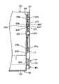
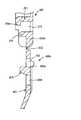
次に、図14及び図15を用いて、ヒンジ結合を構成する一例としての長側壁200に形成されたヒンジ雄部203と底部100の長辺部101に形成されたヒンジ雌部106の詳細について説明する。
【0062】
この実施例は、従来、長側壁200に配設されたヒンジ雄部203の垂直片203aの下端と、底部100の二重壁部104の水平壁104cの上面との間に形成されていた間隙を、実質的になくしたものである。
【0063】
そのために、折り畳みコンテナーが組み立てられた状態において、底部100の端部壁105の内面105bと、底部100の二重壁部104の水平壁104cとにより形成される隅部Aに位置する、長側壁200に配設されたヒンジ雄部203の垂直片203aのほぼ四分の一の領域の半径r1と、ヒンジ雄部203の水平ピン203bの中心点c1と端部壁105の内面105bとの距離d1と、水平ピン203bの中心点c1と二重壁部104の水平壁104cの上面との距離d2とが、ほぼ等しくなるように構成するとともに、水平ピン203bの中心点c1と長側壁200の板状部201の内面201bとの距離d3と、水平ピン203bの中心点c1と二重壁部104の水平壁104cの上面との距離d2とが、ほぼ等しくなるように構成したものである。このように構成するために、長側壁200に形成されたヒンジ雄部203の水平ピン203bの中心点c1が、長側壁200の厚さ方向の中心線L1から、所定量d4だけ、長側壁200の板状部201の内面201b側、即ち、長側壁200の回転側にずらされている。
【0064】
要するに、長側壁200に形成されたヒンジ雄部203の水平ピン203bの中心点c1と底部100の端部壁105の内面105bとの距離d1、水平ピン203bの中心点c1と底部100の二重壁部104の水平壁104cの上面との距離d2及び水平ピン203bの中心点c1と長側壁200の板状部201の内面201bとの距離d3を、いずれも、長側壁200に形成されたヒンジ雄部203を構成する垂直片203aの下部のほぼ半円形部203a’の半径r1と、ほぼ等しくすることにより、長側壁200に形成されたヒンジ雄部203の垂直片203aの下端と、底部100の二重壁部104の水平壁104cの上面との間にできる間隙を、実質的なくし、この間隙への異物の侵入を防止するとともに、折り畳みコンテナーの折り畳みに際して、長側壁2がほぼ水平になるまで倒れることができるようにしたものである。
【0065】
このように構成することにより、図1に示されているように、折り畳みコンテナーが組み立てられた状態において、長側壁200に形成されたヒンジ雄部203の垂直片203aの下端と、底部100の二重壁部104の水平壁104cの上面との間には、実質的な間隙がないので、この間隙に、折り畳みコンテナーに収容された物品やごみ等の異物が入り込むようなことがない。
【0066】
また、水平ピン203bの中心点c1と長側壁200の板状部201の内面201bとの距離d3と、水平ピン203bの中心点c1と底部100の二重壁部104の水平壁104cの上面との距離d2とが、ほぼ等しくなるように構成されているので、図2に示されているように、折り畳みコンテナーの折り畳みに際して、長側壁200がほぼ水平になるまで倒れることができ、水平ピン203bの中心点c1から見て、長側壁200が上方に傾斜することがないので、従って、折り畳みコンテナーを薄く折り畳むことができる。
【0067】
また、ヒンジ雌部106のフック106bの上部外周面に、底部100の端部壁105から、ヒンジ雌部106の板状片106aに向かって、上方に傾斜する傾斜面106cが形成されている。この傾斜面106cは、底部100と長側壁200とをヒンジ結合させるために、長側壁200を、上方から下降させた際に、図15に示されているように、長側壁200に形成されたヒンジ雄部203の水平ピン203bが、傾斜面106cに載置されるような幅を有している。
【0068】
底部100と長側壁200をヒンジ結合させる場合には、先ず最初に、長側壁200を、上方から下降させて、図15に示されているように、長側壁200に形成されたヒンジ雄部203の水平ピン203bを、底部100に形成されたヒンジ雌部106のフック106bの傾斜面106cに当接させる。その後、更に、長側壁200を下降させると、水平ピン203bは、フック106bの傾斜面106cに沿って、端部壁105方向に移動する。そして、長側壁200に形成されたヒンジ雄部203の水平ピン203bが、端部壁105に当接した後に、更に、長側壁200を下降させると、ヒンジ雌部106は、図15において、その弾性力に抗して、右方向に傾動し、端部壁105とフック106bの先端との間に、水平ピン203bが通過可能な間隙が形成される。この間隙を通過した水平ピン203bが、ヒンジ雌部106のフック106bの先端を超えて下方に移動した時点で、ヒンジ雌部106は、その弾性力により、元の位置に復帰するとともに、ヒンジ雄部203の水平ピン203bは、ヒンジ雌部106のフック116bの凹部106b’に嵌合されて、ヒンジ雌部106とヒンジ雄部203とからなるヒンジ部を介して、底部100と長側壁200とがヒンジ結合されることになる。
【0069】
上述したように、ヒンジ雌部106のフック106bの上部外周面には、長側壁200を、上方から下降させた際に、長側壁200に形成されたヒンジ雄部203の水平ピン203bが載置される、底部100の端部壁105方向に向かって下方に傾斜する傾斜面106cが形成されているので、長側壁200に形成されたヒンジ雄部203の水平ピン203bが、底部100に形成されたヒンジ雌部106の板状片106a方向に移動するようなことがなく、従って、従来のように、ヒンジ雄部の水平ピンが、ヒンジ雌部のフックの凹部に嵌合されず、底部と長側壁とのヒンジ結合が失敗するというようなことが防止できる。
【0070】
次に、図8及び図16〜図19を用いて、一例として、長側壁200と一体に成形されたカード差し400について説明する。
【0071】
カード差し400は、以下に説明するカード押さえ条片401等から形成されているカード差し部材400aを、2個以上、並設することにより構成されている。以下に、カード差し400を構成するカード差し部材400aの1つについて説明する。
【0072】
カード差し部材400aを構成するカード押さえ条片401は、一例として、長側壁200の下部水平枠202の下面に形成されたヒンジ雄部203の垂直片203aと、下部ブロック204の垂直片204aとの間に形成された連結壁204bの下端に連接された薄肉連結部402に連結されており、その形状は、細長の帯状に形成されている。
【0073】
カード差し部材400aが、長側壁200と一体に成形された時点では、図16や図19等に示されているように、カード押さえ条片401は、長側壁200の下端から、薄肉連結部402を介して、ほぼ下方に垂直に垂下されている。薄肉連結部402付近のカード押さえ条片401には、第1嵌合孔403が穿設されており、また、薄肉連結部402に対して第1嵌合孔403より遠い位置には、第2嵌合孔404が穿設されている。また、カード押さえ条片401の第1嵌合孔403と第2嵌合孔404間に位置するとともに、長側壁200の板状部201の外面201aから離れる方向に延在する係合凸部405が形成されている。
【0074】
211は、長側壁200の下部水平枠202上に、カード押さえ条片401の幅w1より、若干、広い内幅w2を有するように配設された一対の規制ブロックであり、規制ブロック211の奥行きx1は、長側壁200の下部水平枠202の奥行きx2とほぼ同じに形成されている。また、規制ブロック211は、長側壁200の板状部201と一体の連結ブロック212により連結されている。
【0075】
連結ブロック212のほぼ中央部の上部には、長側壁200の板状部201の外面201aから離れる方向に水平に延在する係止片213が形成されており、係止片213の下面先端には、下方に延在する係止突起213aが形成されている。係止片213の下方には、係止片213と同じ方向に、係止片213とほぼ平行に延在する案内ブロック214が形成されている。215は、係止片213と案内ブロック214との間に形成された透孔であり、カード差し部材400aを、長側壁200と一体に成形するための金型部材により形成されるものである。
【0076】
上述したように、カード差し部材400aが、長側壁200と一体に成形された時点では、カード押さえ条片401は、長側壁200の下端から、薄肉連結部402を介して、ほぼ下方に垂直に垂下されているが、この状態から、カード押さえ条片401を、薄肉連結部402を折り曲げるように、長側壁200の板状部201の外面201a方向に回動させると、先ず最初に、カード押さえ条片401に形成された第1嵌合孔403に、長側壁200に形成された案内ブロック214が嵌合し、更に、カード押さえ条片401の長側壁200の板状部201の外面201a方向への回動を続けると、カード押さえ条片401に形成された係合凸部405が、長側壁200に形成された案内ブロック214と係止片213との間隙に押し込まれ、該間隙に押し込まれた係合凸部405は、係止片213を上方に弾性変形させて、案内ブロック214と係止片213との間隙を拡げながら、該間隙に挿通される。カード押さえ条片401に形成された係合凸部405が、長側壁200に形成された案内ブロック214と係止片213との間隙を通過した後は、係止片213は、係止片213自体の弾性により、下方に回動し、係止片213の係止突起213aが、係合凸部405の先端の上部角部405aに係止され、カード押さえ条片401が、長側壁200に形成された係止片213に係合保持されるように構成されている。
【0077】
また、カード押さえ条片401は、第1嵌合孔403、第2嵌合孔404及び係合凸部405が形成された、薄肉連結部402側に位置する基部401aと、基部401aに連接されているとともに、外側に傾斜した中間部401bと、中間部401bの先端を外側に屈曲して形成されたカード案内部401cとから形成されており、カード押さえ条片401に形成された係合凸部405の先端の上部角部405aが、長側壁200に形成された係止片213の係止突起213aに係止されて、カード差し部材400aが組み立てられた時点において、カード押さえ条片401の中間部401bとカード案内部401cとの境界線に位置する屈曲部401dが、長側壁200の板状部201の外面201aに当接するように構成されており、且つ、屈曲部401dより上方に位置するカード案内部401cの内面401c’と長側壁200の板状部201の外面201aとの間には、カード案内部401cの内面401c’と長側壁200の板状部201の外面201aとの間隔が、下方に行くに従って、徐々に狭くなる、楔状空間406が形成されるように構成されている。
【0078】
上述したようにして、2つ以上のカード差し部材400aを組み立てることにより、カード差し400が形成されることになる。このようにして形成されたカード差し400に、カード407を保持させる際には、カード407の下辺407aを、上述した楔状空間406に挿入し、次いで、更に、カード407を押し下げると、カード407は、長側壁200の板状部201の外面201aに当接されているカード押さえ条片401の屈曲部401dを、長側壁200の板状部201の外面201aから離反させる方向に移動させて、長側壁200の板状部201の外面201aとカード押さえ条片401の屈曲部401dとの間に、カード407が挿通可能な間隙を形成し、そのまま、該間隙を通過し、カード407の下辺407aが、規制ブロック211や連結ブロック212の上面に当接するまで、カード407を押し下げる。このようにして、カード407が、2つ以上のカード差し部材400aに保持されることになる。そして、2つ以上のカード差し部材400aに保持されたカード407は、カード押さえ条片401の屈曲部401dにより、長側壁200の板状部201の外面201aに圧接されるように構成されているので、カード407が、簡単に、移動したり、容器用カード差し400から外れるようなことがない。
【0079】
上述したカード差し部材400aは、長側壁200と一体に成形されるが、長側壁200が不透明な樹脂で成形された場合には、カード差し部材400aも、同様の不透明な樹脂で成形されることになり、従って、カード差し部材400aに保持されたカード407の一部が、カード差し部材400aに隠れて見えなくなる。従って、このような問題を解決するために、カード差し部材400aを構成するカード押さえ条片401は、細長の帯状に形成されている。
【0080】
また、カード差し部材400aのカード押さえ条片401を成形するための金型空間には、透明な或いは半透明な樹脂を注入し、また長側壁200を成形するための金型空間には、適宜、色付き樹脂を注入することにより、透明な或いは半透明なカード差し部材400aと、色付きの長側壁200とを、一体に成形することもできる。
【0081】
本発明は、上述したように、カード差し部材400aを構成するカード押さえ条片401が、薄肉連結部402を介して、長側壁200と一体に形成されているので、カード押さえ条片401を、薄肉連結部402を折り曲げるように、長側壁200の板状部201の外面201b方向に回動させるだけで、簡単に、組み立てることができる。
【0082】
また、カード差し部材400aを構成するカード押さえ条片401が、細長の帯状に形成されているので、カード407のカード押さえ条片401に隠れる部分が少なく、従って、カード407に記載或いは記憶された、物品の行き先、物品名、種類、数量等に関する情報の読み取りに、支障をきたすようなことがない。
【0083】
2つ以上のカード差し部材400aに保持されたカード407が、カード押さえ条片401の屈曲部401dにより、長側壁200の板状部201の外面201aに圧接されるように構成されているので、カード407が、簡単に、移動したり、カード差し400から外れるようなことがない。
【0084】
組み立てられたカード押さえ条片401は、長側壁200に形成された一対の規制ブロック211間に位置するように構成されているので、カード押さえ条片401に、外力が加わり、カード押さえ条片401が、長側壁200の板状部201の外面201aに沿った方向に移動しようとしても、規制ブロック211により、その移動が抑制されるので、従って、強度的に弱い薄肉連結部402が損傷するようなことが防止できるとともに、カード押さえ条片401の移動により、カード差し部材400aに保持されたカード407が、外れるようなことが防止できる。
【0085】
また、図1等に示されているように、長側壁200には、長側壁200の上端部内側を切り欠くことにより、切り欠き部216が形成されており、同様に、短側壁300にも、短側壁300の上端部内側を切り欠くことにより、切り欠き部310が形成されている。このような切り欠き部216、310には、組み立てられた折り畳みコンテナーを積み重ねた時に、上に位置する折り畳みコンテナーの底部100の底部嵌合部100aが嵌合されるように構成されている。
【0086】
上述した折り畳みコンテナーを構成する底部100、長側壁200及び短側壁300は、それぞれ、射出成形等により、合成樹脂で一体に成形され、その後、上述したように、底部100、長側壁200及び短側壁300を、ヒンジ結合により連結することにより、折り畳みコンテナーに組み立てられるように構成されている。
【0087】
【発明の効果】
本発明は、以上説明した構成を有しているので、以下に記載する効果を奏するものである。
【0088】
底部には、折り畳まれた状態の折り畳みコンテナーの底部が嵌合可能な係止ブロックが形成されており、且つ、側壁には、組み立てられた状態の折り畳みコンテナーの係止ブロックが挿入可能な下方が開放された凹部が形成されているので折り畳まれた状態の折り畳みコンテナーを安定した状態で、積み重ねることができるとともに、係合枠部を介して、側壁同士及び側壁と底部が係合し合うように構成されているので、箱型に組み立てられ状態の折り畳みコンテナーが強固なものとなる。
【0089】
相対する一方の側壁には、折り畳んだ際に、上方に突出する係止ブロックが挿入可能な透孔が穿設されているので、係止ブロックが、折り畳みコンテナーの折り畳み作業の障害になるようなことがない。
【0090】
側壁の係合枠部に形成された係合突起が、底部に形成された嵌合部の透孔に嵌合されるように構成されているので、折り畳みコンテナーが箱型に組み立てられた際に、底部と側壁との結合強度が向上するとともに、底部に対する側壁の動きが規制されることになり、従って、底部に対して側壁が大きく移動することにより、底部と側壁を連結するヒンジ結合部が損傷するようなことが防止できる。
【0091】
底部に対して側壁が垂直に立てられた際に、側壁の下面と底部の上面が、その一部において、面接触するように構成されているので、側壁にかかった負荷を、この面接触部分で負担することができ、側壁にかかった負荷が、ヒンジ結合部に及んでヒンジ結合部が損傷するようなことが防止できる。
【0092】
カード差しを構成するカード押さえ条片が、薄肉連結部を介して側壁と一体に形成されているので、カード押さえ条片を、薄肉連結部を折り曲げるように、側壁方向に回動させるだけで、簡単に、組み立てることができる。
【図面の簡単な説明】
【図1】図1は本発明の折り畳みコンテナーの組み立てられた状態の斜視図である。
【図2】図2は本発明の折り畳みコンテナーの組み立て途中の斜視図である。
【図3】図3は本発明の折り畳みコンテナーの折り畳まれた状態の斜視図である。
【図4】図4は本発明の折り畳みコンテナーの底部の斜視図である。
【図5】図5は本発明の折り畳みコンテナーの底部と長側壁のヒンジ結合を説明するための底部と長側壁の分解部分斜視図である。
【図6】図6は本発明の折り畳みコンテナーの底部と長側壁の端部付近の分解部分斜視図である。
【図7】図7は本発明の折り畳みコンテナーの折り畳まれた状態の裏面斜視図である。
【図8】図8は本発明の折り畳みコンテナーの長側壁の斜視図である。
【図9】図9は本発明の折り畳みコンテナーの長側壁の部分斜視図である。
【図10】図10は本発明の折り畳みコンテナーの長側壁の係合枠部と短側壁の係合枠部とが係合される前の長側壁と短側壁の垂直断面図である。
【図11】図11は本発明の折り畳みコンテナーの短側壁の斜視図である。
【図12】図12は本発明の折り畳みコンテナーの短側壁の部分斜視図である。
【図13】図13は本発明の折り畳みコンテナーの長側壁の係合枠部と短側壁の係合枠部とが係合された状態の長側壁と短側壁の垂直断面図である。
【図14】図14は本発明の折り畳みコンテナーの底部と長側壁のヒンジ部を含む垂直断面図である。
【図15】図15は本発明の折り畳みコンテナーの底部と長側壁のヒンジ部がヒンジ結合される直前の底部と長側壁のヒンジ部を含む垂直断面図である。
【図16】図16は本発明の折り畳みコンテナーの長側壁に配設されるカード差しの組み立て前の拡大斜視図である。
【図17】図17は本発明の折り畳みコンテナーの長側壁に配設されるカード差しの組み立て前の垂直断面図である。
【図18】図18は本発明の折り畳みコンテナーの長側壁に配設されるカード差しの組み立て後の部分垂直断面図である。
【図19】図19はカード差しが配設された本発明の折り畳みコンテナーの長側壁の斜視図である。
【符号の説明】
100・・・・・・・・・・底部
106・・・・・・・・・・ヒンジ雌部
108・・・・・・・・・・長辺部側係止ブロック
109・・・・・・・・・・端部係止ブロック
113・・・・・・・・・・短辺側係止ブロック
200・・・・・・・・・・長側壁
203・・・・・・・・・・ヒンジ雄部
207・・・・・・・・・・係合枠部
300・・・・・・・・・・短側壁
303・・・・・・・・・・ヒンジ雄部
308・・・・・・・・・・係合枠部
400・・・・・・・・・・カード差し
401・・・・・・・・・・カード押さえ条片[0001]
BACKGROUND OF THE INVENTION
The present invention relates to a folding container that can be folded so that a side wall disposed so as to surround the bottom portion overlaps the bottom portion.
[0002]
[Prior art]
Conventionally, as an example, a long side wall connected via a hinge part to the opposite long side part of the bottom part formed in a substantially rectangular plane shape, and a hinge part to the short side part of the same bottom part. Folding containers are known consisting of short side walls connected together, and in the folded state, the short side wall is folded over the bottom, and further, the long side wall is folded thereon, and It is configured to be assembled into a box-type folding container by standing the folded long side wall perpendicular to the bottom and then standing the folded short side wall perpendicular to the bottom. ing.
[0003]
In the folded state of the folding container, the bottom is located at the bottom, the short side wall folded so as to overlap is located on the bottom, and the long side wall folded so as to overlap is located on the bottom. It will be. When stacking the folded containers in such a folded state, the bottom of the folded container in the folded state is placed on the long side wall of the folded container in the folded state located below. It will be. In addition, a substantially L-shaped fitting bank is formed in the vicinity of both lower corners (corners located on the bottom side) of both long side walls of the folding container, and the two long side walls in the folded state are formed. In these four corners, fitting banks having a substantially L-shaped planar shape are located. When the folded containers in the folded state are stacked, the folded state in which the folded container is located in the upper part of the fitting bank located in the four corners of the two long side walls of the folded container in the folded state. Since the bottom of the folding container is configured to be fitted, the horizontal movement of the folded container in the upper position relative to the folded container in the lower position is limited, A large number of stacked folding containers are stably stacked so that they do not fluctuate and collapse.
[0004]
[Problems to be solved by the invention]
As described above, in the conventional folding container, in order to stack a large number of folded folding containers in a stable state, there are fitting banks near both lower corners of the long side wall of the folding container. Although it is formed, the fitting bank portion protrudes from the long side wall in the assembled state, and therefore, two assembled folding containers are juxtaposed so that the long side walls abut each other. In this case, there is a wasteful gap between the folding containers arranged side by side, and thus there is a problem that the storage space of the assembled folding containers increases and the storage efficiency decreases. Further, since the fitting bank portion is formed, the thickness of the long side wall is increased, and therefore, the inner volume is small with respect to the outer dimension of the assembled folding container, and the housing efficiency of the assembled folding container is poor. there were.
[0005]
Further, in the conventional folding container, since the engagement between the long side wall and the short side wall is not sufficient in the assembled state, the long side wall and the short side wall are stacked as when the folded containers in the assembled state are stacked. When a load is applied to the side wall from above, there is a problem that the long side wall and the short side wall are disengaged.
[0006]
Furthermore, in the conventional folding container, when a load is applied to the long side wall and the short side wall from above, the load is applied to the hinge part connecting the bottom part and the long side wall and the bottom part and the short side wall, and the hinge part is damaged. There was a problem.
[0007]
Furthermore, in the conventional folding container, there is a problem in the structure of the hinge part connecting the bottom part and the long side wall and the bottom part and the short side wall. There was a problem that the assembling workability of the folding container was poor.
[0008]
Furthermore, conventionally, since the card holder disposed in the folding container is separately manufactured and attached to the long side wall or the short side wall, it takes time and labor to install the card holder, and consequently There was a problem that the price of the folding container increased.
[0009]
An object of the present invention is to solve the problems of the above-described conventional folding container and to provide a folding container with improved handleability and accommodation efficiency.
[0010]
[Means for Solving the Problems]
In order to achieve the above-mentioned object, the present invention can fold a side wall disposed so as to surround the bottom portion so as to overlap the bottom portion, and the side wall standing upright with respect to the bottom portion falls inward. In the folding container in which the side walls are engaged with each other so that adjacent side walls engage with each other, first, the bottom of the folded container can be fitted to the bottom. A locking block is formed on the side wall, and a recess is formed on the side wall through which the locking block of the folded folding container in the assembled state can be inserted. The side walls and the side walls and the bottom are engaged with each other. Second, the opposing one side wall can be inserted with a locking block that protrudes upward when folded. Hole drilled Thirdly, the engagement projection formed on the engagement frame portion of the side wall is configured to be fitted into the through hole of the fitting portion formed on the bottom portion. Fourthly, when the side wall is erected vertically with respect to the bottom, the lower surface of the side wall and the upper surface of the bottom are partly in surface contact with each other. Is a card holding strip that forms a card slot, and is formed integrally with the side wall via a thin connecting portion.
[0011]
【Example】
Examples of the present invention will be described below. However, the present invention is not limited to these examples as long as the gist of the present invention is not exceeded.
[0012]
[0013]
As shown in FIG. 1, in order to fold a folding container assembled in a box shape, first, the
[0014]
Next, the
[0015]
The
[0016]
In addition, a plate-
[0017]
The
[0018]
At both ends of the
[0019]
The
[0020]
By extending both ends of the
[0021]
In addition, 114 is formed in the middle of the
[0022]
As will be described later, the card insert is disposed on the
[0023]
Furthermore, if the size of the folding container is different, in other words, if the size of the
[0024]
Next, the long side wall 2 will be described with reference to FIGS. 2, 5, 6, and 8 to 10.
[0025]
The
[0026]
[0027]
The end face 203 a ″ on the
[0028]
A plurality of
[0029]
[0030]
A
[0031]
And in the state in which the folding container was assembled, it is comprised so that the upper end of the
[0032]
In addition, an abutting
[0033]
When the
[0034]
[0035]
When the
[0036]
The diameter between the
[0037]
Next, the
[0038]
Similarly to the
[0039]
Also, a
[0040]
An upper
[0041]
The
[0042]
An
[0043]
Further, an intermediate fitting
[0044]
The gap between the
[0045]
Next, the assembly of the bottom 100, the
[0046]
The
[0047]
To assemble from the folded state shown in FIG. 3 as shown in FIG. 1, the
[0048]
As described above, when the
[0049]
As described above, when the
[0050]
Further, the
[0051]
As described above, the lower
[0052]
Further, the lower
[0053]
Furthermore, when the folding container is assembled, the lower fitting
[0054]
Furthermore, a pair of locking
[0055]
As described above, in a state where the folding container is assembled, the long
[0056]
As described above, the
[0057]
When the assembled folded container shown in FIG. 1 is folded as shown in FIG. 3, first, the
[0058]
Further, since the short
[0059]
When the folded folding containers shown in FIG. 3 are stacked, the
[0060]
In the embodiment described above, the arrangement and number of the long side locking blocks 108, the end locking blocks 109, and the short side locking blocks 113 formed on the bottom 100 are limited to the above-described embodiments. is not. In addition, when the long
[0061]
Next, with reference to FIGS. 14 and 15, details of the hinge
[0062]
In this embodiment, the gap formed between the lower end of the
[0063]
Therefore, in a state in which the folding container is assembled, the long side wall is located at the corner A formed by the
[0064]
In short, the distance d1 between the center point c1 of the
[0065]
With this configuration, as shown in FIG. 1, when the folding container is assembled, the bottom end of the
[0066]
Further, the distance d3 between the center point c1 of the
[0067]
In addition, an
[0068]
When the
[0069]
As described above, the
[0070]
Next, as an example, a
[0071]
The
[0072]
As an example, the
[0073]
When the
[0074]
[0075]
A
[0076]
As described above, when the
[0077]
The
[0078]
As described above, the
[0079]
The
[0080]
In addition, a transparent or translucent resin is injected into a mold space for molding the
[0081]
In the present invention, as described above, since the
[0082]
Further, since the
[0083]
Since the
[0084]
Since the assembled
[0085]
Further, as shown in FIG. 1 and the like, the
[0086]
The
[0087]
【The invention's effect】
Since the present invention has the above-described configuration, the following effects can be achieved.
[0088]
The bottom is formed with a locking block into which the bottom of the folded container in the folded state can be fitted, and the side wall has a lower part into which the locking block of the folded container in the assembled state can be inserted. Since the opened recesses are formed, the folded containers in the folded state can be stacked in a stable state, and the side walls and the side walls and the bottom part can be engaged with each other via the engaging frame part. Since it is configured, the folding container assembled in a box shape is strong.
[0089]
The opposite side wall has a through-hole into which a locking block protruding upward can be inserted when folded, so that the locking block may interfere with the folding operation of the folding container. There is nothing.
[0090]
Since the engagement protrusion formed on the engagement frame portion of the side wall is configured to be fitted into the through hole of the fitting portion formed on the bottom portion, when the folding container is assembled into a box shape As a result, the strength of the coupling between the bottom and the side wall is improved, and the movement of the side wall with respect to the bottom is restricted. Therefore, when the side wall largely moves with respect to the bottom, the hinge coupling portion that connects the bottom and the side wall is provided. Damage can be prevented.
[0091]
Since the lower surface of the side wall and the upper surface of the bottom portion are configured to be in surface contact with each other when the side wall is erected vertically with respect to the bottom portion, a load applied to the side wall can be reduced. It is possible to prevent the load on the side wall from reaching the hinge joint and damaging the hinge joint.
[0092]
Since the card pressing strip constituting the card insert is formed integrally with the side wall via the thin connecting portion, the card pressing strip is simply rotated in the side wall direction so as to bend the thin connecting portion. Easy to assemble.
[Brief description of the drawings]
FIG. 1 is a perspective view of a folding container according to the present invention in an assembled state.
FIG. 2 is a perspective view in the middle of assembling the folding container of the present invention.
FIG. 3 is a perspective view showing a folded state of the folding container of the present invention.
FIG. 4 is a perspective view of the bottom of the folding container of the present invention.
FIG. 5 is an exploded partial perspective view of the bottom and the long side wall for explaining the hinge connection between the bottom and the long side wall of the folding container according to the present invention.
FIG. 6 is an exploded partial perspective view of the folding container according to the present invention near the bottom and the end of the long side wall.
FIG. 7 is a rear perspective view of the folding container of the present invention in a folded state.
FIG. 8 is a perspective view of the long side wall of the folding container of the present invention.
FIG. 9 is a partial perspective view of the long side wall of the folding container of the present invention.
FIG. 10 is a vertical sectional view of the long side wall and the short side wall before the engagement frame portion of the long side wall and the engagement frame portion of the short side wall of the folding container of the present invention are engaged.
FIG. 11 is a perspective view of the short side wall of the folding container of the present invention.
FIG. 12 is a partial perspective view of a short side wall of the folding container of the present invention.
FIG. 13 is a vertical cross-sectional view of the long side wall and the short side wall in a state in which the engagement frame portion of the long side wall and the engagement frame portion of the short side wall of the folding container of the present invention are engaged.
FIG. 14 is a vertical sectional view including the bottom part of the folding container and the hinge part of the long side wall of the present invention.
FIG. 15 is a vertical sectional view including the bottom portion and the long side wall hinge portion just before the bottom portion and the long side wall hinge portion of the folding container of the present invention are hinge-joined.
FIG. 16 is an enlarged perspective view before assembling the card holder disposed on the long side wall of the folding container of the present invention.
FIG. 17 is a vertical cross-sectional view before assembling the card holder disposed on the long side wall of the folding container of the present invention.
FIG. 18 is a partial vertical cross-sectional view after assembling the card holder disposed on the long side wall of the folding container of the present invention.
FIG. 19 is a perspective view of the long side wall of the folding container of the present invention in which a card slot is disposed.
[Explanation of symbols]
100 .... Bottom
106 ・ ・ ・ ・ ・ ・ ・ ・ ・ ・ Hinge female part
108 ・ ・ ・ ・ ・ ・ ・ ・ ・ ・ Long side lock block
109 ・ ・ ・ ・ ・ ・ ・ ・ ・ ・ End locking block
113 ......... Short side locking block
200 ... Long side wall
203 ..... Hinge male part
207 ..... engagement frame part
300 …… Short side wall
303 ... Hinge male part
308 ..... engagement frame part
400 .... Card insertion
401... Card holding strip
Claims (5)
Translated fromJapanesePriority Applications (6)
| Application Number | Priority Date | Filing Date | Title |
|---|---|---|---|
| JP31786599AJP3707973B2 (en) | 1999-11-09 | 1999-11-09 | Folding container |
| US09/635,693US6820761B1 (en) | 1999-11-09 | 2000-08-10 | Folding container |
| CA002316423ACA2316423C (en) | 1999-11-09 | 2000-08-18 | Folding container |
| DE60031358TDE60031358T2 (en) | 1999-11-09 | 2000-08-31 | Collapsible container |
| EP00118857AEP1114779B1 (en) | 1999-11-09 | 2000-08-31 | Collapsible container |
| AT00118857TATE342842T1 (en) | 1999-11-09 | 2000-08-31 | COLLAPSIBLE CONTAINER |
Applications Claiming Priority (1)
| Application Number | Priority Date | Filing Date | Title |
|---|---|---|---|
| JP31786599AJP3707973B2 (en) | 1999-11-09 | 1999-11-09 | Folding container |
Publications (2)
| Publication Number | Publication Date |
|---|---|
| JP2001130554A JP2001130554A (en) | 2001-05-15 |
| JP3707973B2true JP3707973B2 (en) | 2005-10-19 |
Family
ID=18092931
Family Applications (1)
| Application Number | Title | Priority Date | Filing Date |
|---|---|---|---|
| JP31786599AExpired - Fee RelatedJP3707973B2 (en) | 1999-11-09 | 1999-11-09 | Folding container |
Country Status (6)
| Country | Link |
|---|---|
| US (1) | US6820761B1 (en) |
| EP (1) | EP1114779B1 (en) |
| JP (1) | JP3707973B2 (en) |
| AT (1) | ATE342842T1 (en) |
| CA (1) | CA2316423C (en) |
| DE (1) | DE60031358T2 (en) |
Cited By (1)
| Publication number | Priority date | Publication date | Assignee | Title |
|---|---|---|---|---|
| JP2007161258A (en)* | 2005-12-09 | 2007-06-28 | Seiko Epson Corp | Foldable container |
Families Citing this family (85)
| Publication number | Priority date | Publication date | Assignee | Title |
|---|---|---|---|---|
| JP3274857B2 (en)* | 2000-04-10 | 2002-04-15 | 岐阜プラスチック工業株式会社 | Folding container |
| US6631822B1 (en)* | 2000-10-28 | 2003-10-14 | Rehrig Pacific Company | Collapsible container |
| US20020108950A1 (en)* | 2001-02-14 | 2002-08-15 | Moorman Stephen E. | Collapsible container |
| SE0103685D0 (en)* | 2001-11-05 | 2001-11-05 | Arca Systems Ab | Collapsible container |
| US6899242B2 (en)* | 2001-12-20 | 2005-05-31 | Rehrig Pacific Company | Collapsible container with recessed side-panel latch |
| US7104414B2 (en)* | 2002-01-12 | 2006-09-12 | Rehrig Pacific Company | Collapsible container |
| US6863180B2 (en) | 2002-02-15 | 2005-03-08 | Rehrig Pacific Company | Collapsible container |
| US7478726B2 (en) | 2002-05-28 | 2009-01-20 | Rehrig Pacific Company | Collapsibile crate with support members |
| US7059489B2 (en) | 2002-10-11 | 2006-06-13 | Rehrig Pacific Company | Portable storage device |
| US7017766B2 (en)* | 2003-03-10 | 2006-03-28 | Rehrig Pacific Company | Collapsible container with side wall latching capability |
| US7100786B2 (en) | 2003-03-21 | 2006-09-05 | Rehrig Pacific Company | Collapsible container |
| US7195127B2 (en)* | 2003-05-13 | 2007-03-27 | Rehrig Pacific Company | Collapsible container |
| US7306159B1 (en)* | 2003-06-07 | 2007-12-11 | Rochelo Donald R | Protective case for six different sized memory cards |
| GB2403944A (en)* | 2003-07-10 | 2005-01-19 | Sec Sea Pak Ltd | A foldable storage crate |
| DE10357278A1 (en)* | 2003-12-05 | 2006-03-02 | J. Eberspächer GmbH & Co. KG | transport system |
| US20050155967A1 (en)* | 2004-01-21 | 2005-07-21 | Vial Ignacio B. | Locking arrangements for side walls of rigid, foldable or collapsible boxes |
| US7234598B2 (en)* | 2004-03-16 | 2007-06-26 | Schaefer Systems International, Inc. | Material handling container with card holder |
| US7441673B2 (en)* | 2004-03-16 | 2008-10-28 | Mcdade Clinton | Material handling container with card holder |
| US7475526B2 (en)* | 2004-04-19 | 2009-01-13 | Polymer Logistics (Israel) Ltd. | Knock-down crate with walls stored in base and method employing such a crate |
| US7296704B2 (en)* | 2004-08-11 | 2007-11-20 | Ferrini Jonathan B | Collapsible container |
| US20060213150A1 (en)* | 2005-03-24 | 2006-09-28 | Sonon James A | Method for product handling using a configurable display container |
| WO2006119513A1 (en)* | 2005-04-29 | 2006-11-09 | Miguel Gonsalves Carreira | A collapsible container |
| CN1880186B (en)* | 2005-06-16 | 2011-07-20 | 三甲株式会社 | Folding container |
| TR200502815A2 (en)* | 2005-07-19 | 2007-10-22 | Odesa Gel��T�R�Lm�� Pol�Mer Yatirimlari Ve Di� T�Caret A.�. | Lock system for collapsible safes. |
| JP4764678B2 (en)* | 2005-08-26 | 2011-09-07 | 三甲株式会社 | Foldable container |
| US7357269B2 (en) | 2005-11-01 | 2008-04-15 | Rehrig Pacific Company | Container |
| WO2008094131A2 (en)* | 2007-01-31 | 2008-08-07 | Ay Kasa Polimer Ambalaj Ve Tasima Sistemleri Sanayi Ticaret A.S. | Centralization and lock system used in folded carrying boxes |
| US20080296183A1 (en)* | 2007-05-29 | 2008-12-04 | Meers Ryan C | Tray and dolly |
| US20080296308A1 (en)* | 2007-05-30 | 2008-12-04 | Daniel Barbalho | Collapsible container |
| US7641066B2 (en)* | 2007-06-11 | 2010-01-05 | Rehrig Pacific Company | Collapsible container |
| US20090057191A1 (en)* | 2007-08-27 | 2009-03-05 | Temple Jr Nicholas B | Stackable and collapsible pallet container |
| US7717283B2 (en) | 2007-11-06 | 2010-05-18 | Rehrig Pacific Company | Collapsible container |
| JP4942043B2 (en)* | 2007-11-28 | 2012-05-30 | 三甲株式会社 | Folding container |
| US7861458B2 (en)* | 2007-12-13 | 2011-01-04 | Rehrig Pacific Company | Collapsible container |
| JP4817398B2 (en)* | 2008-01-08 | 2011-11-16 | サミー株式会社 | Board case for gaming machines |
| US8261923B2 (en)* | 2008-04-22 | 2012-09-11 | Otto Industries North America, Inc. | Collapsible container |
| US7861879B2 (en) | 2008-05-02 | 2011-01-04 | Orbis Corporation | Folding container |
| ES2411730T3 (en)* | 2008-06-17 | 2013-07-08 | Georg Utz Holding Ag | Folding container for transport and storage |
| CA2686829A1 (en) | 2008-12-02 | 2010-06-02 | Rehrig Pacific Company | Collapsible container |
| DE102009049103A1 (en)* | 2009-04-15 | 2010-11-04 | Ifco Systems Gmbh | Crate with foldable and removable outer walls |
| DE102009049185A1 (en) | 2009-04-15 | 2011-01-05 | Ifco Systems Gmbh | Crate with foldable side walls with stable sidewall structure |
| BRPI0924017B1 (en) | 2009-04-15 | 2019-03-26 | Ifco Systems Gmbh | CONTAINER UNDERSTANDING A FOLDING SIDE WALL. |
| DE102009049186A1 (en) | 2009-04-15 | 2010-11-04 | Ifco Systems Gmbh | Crate with foldable and self-locking side walls |
| DE102009049184A1 (en) | 2009-04-15 | 2010-11-04 | Ifco Systems Gmbh | Crate with foldable side walls and locking mechanisms with overload protection |
| US20110139775A1 (en) | 2009-12-16 | 2011-06-16 | Roger Nolan | Fork Tine Notch |
| EP2390199B1 (en) | 2010-05-27 | 2013-07-10 | Rehrig Pacific Company | Collapsible dual height stacking container |
| JP5420496B2 (en)* | 2010-07-30 | 2014-02-19 | 三甲株式会社 | Folding container |
| PL2431287T3 (en) | 2010-09-20 | 2013-12-31 | Ifco Systems Gmbh | Crate |
| US9469429B2 (en) | 2010-09-20 | 2016-10-18 | Ifco Systems Gmbh | Crate |
| DE102011001656B4 (en) | 2011-03-02 | 2015-01-08 | Provendor Gmbh | Snap closure on a folding box for the transport and storage of goods of all kinds |
| DE102010054495A1 (en) | 2010-12-14 | 2012-06-14 | Provendor Gmbh | Folding box for transporting and storing goods, comprises five portions, two side walls, two longitudinal walls and base, where short side is provided with size of fifteen point one centimeters |
| US20130299490A1 (en)* | 2012-05-08 | 2013-11-14 | Tosca Services, LLC | Reusable bin |
| CN103569448B (en)* | 2012-08-08 | 2016-01-13 | 康准电子科技(昆山)有限公司 | Containing case |
| US8915397B2 (en) | 2012-11-01 | 2014-12-23 | Orbis Corporation | Bulk container with center support between drop door and side wall |
| US10750727B1 (en) | 2013-02-26 | 2020-08-25 | Tyson Foods, Inc. | Portable basket colony for growing and transport and method of use |
| US9737056B2 (en) | 2013-02-26 | 2017-08-22 | Tyson Foods, Inc. | Portable basket colony for growing and transport and method of use |
| US9708097B2 (en) | 2013-11-15 | 2017-07-18 | Orbis Corporation | Bulk bin with integrated shock absorber |
| US9487326B2 (en) | 2013-11-26 | 2016-11-08 | Orbis Corporation | Bulk bin with panel to panel interlock features |
| MX354768B (en)* | 2013-12-20 | 2018-03-21 | Buckhorn Inc | Collapsible container having foldable side and end panels. |
| US9863174B2 (en) | 2014-06-20 | 2018-01-09 | Orbis Corporation | Hinge rod trap for a collapsible bin |
| US20150375558A1 (en)* | 2014-06-27 | 2015-12-31 | Storex Industries Corporation | Collapsible file box with integrated file hanging rails |
| CN104163295B (en)* | 2014-07-22 | 2017-02-15 | 上海鸿研物流技术有限公司 | Foldable container |
| FR3043074B1 (en)* | 2015-11-04 | 2020-02-28 | Decorec | CONTAINER FOR HANDLING PARTS |
| KR102632306B1 (en) | 2015-11-10 | 2024-01-31 | 한스 우츠 | folding container |
| US10703531B2 (en) | 2016-03-11 | 2020-07-07 | Rehrig Pacific Company | Collapsible crate with wood appearance |
| CN105836254B (en)* | 2016-05-24 | 2018-12-07 | 上海鸿研物流技术有限公司 | Folding carton |
| US10427830B2 (en)* | 2016-10-03 | 2019-10-01 | Schaefer Systems International, Inc. | Rotating sidewall stop for supporting folding sidewalls of a height-extended bulk box |
| DE202016106088U1 (en)* | 2016-10-28 | 2017-02-06 | Georg Utz Holding Ag | Collapsible container |
| DE102017113053B4 (en)* | 2017-06-14 | 2023-01-05 | Schoeller Allibert Gmbh | Large load carrier with pivoting flap |
| US10532853B2 (en)* | 2018-01-05 | 2020-01-14 | Easy Gardener Products, Inc. | Product display container |
| CN208287495U (en)* | 2018-04-18 | 2018-12-28 | 陈思钿 | Removable Multifunctional storage box |
| JP7114062B2 (en)* | 2018-07-04 | 2022-08-08 | 河淳株式会社 | folding storage box |
| US11724857B2 (en) | 2018-08-03 | 2023-08-15 | Wenco S.A. | Mechanism for joining collapsible walls of a plastic container |
| US11597557B2 (en) | 2018-10-04 | 2023-03-07 | Rehrig Pacific Company | Reconfigurable beverage crate |
| US12330840B2 (en)* | 2019-02-04 | 2025-06-17 | Rehrig Pacific Company | Collapsible crate with retractable wall |
| AT522598B1 (en)* | 2019-04-05 | 2021-01-15 | Rudolf Czapek | GARDEN BOX |
| US10758071B1 (en)* | 2019-04-26 | 2020-09-01 | Nanning Fugui Precision Industrial Co., Ltd. | Smart folding box |
| US11312534B2 (en)* | 2019-08-24 | 2022-04-26 | Logistics Advanced Research Center LLC | Modular reusable shipping crate |
| US11634259B2 (en) | 2019-08-24 | 2023-04-25 | Logistics Advanced Research Center LLC | Reusable shipping platform for transporting multiple electrical circuit breakers |
| CN110712827A (en)* | 2019-10-22 | 2020-01-21 | 上海派瑞特塑业有限公司 | Folding transport case |
| US20210323728A1 (en)* | 2020-04-21 | 2021-10-21 | Orbis Corporation | Bread tray merchandiser barrier |
| CN111942707B (en)* | 2020-08-17 | 2024-09-24 | 芜湖勤惠科技有限公司 | Folding type logistics station apparatus |
| CA3172382A1 (en) | 2021-09-16 | 2023-03-16 | Rehrig Pacific Company | Hybrid collapsible crate |
| EP4206085A1 (en)* | 2022-01-03 | 2023-07-05 | Schoeller Allibert GmbH | Reusable transport container with side wall with orientation sensor |
| CN117842501B (en)* | 2024-02-21 | 2025-09-23 | 朴朴科技(福建)有限公司 | A folding basket |
Family Cites Families (16)
| Publication number | Priority date | Publication date | Assignee | Title |
|---|---|---|---|---|
| US1280629A (en)* | 1917-04-09 | 1918-10-08 | William H Appleby | Hinge. |
| FR1040163A (en)* | 1951-06-29 | 1953-10-13 | Folding crate or crate | |
| US4062467A (en)* | 1974-07-27 | 1977-12-13 | Friedrich Wolfgang E | Collapsible transport container |
| DE2734964C2 (en)* | 1977-08-03 | 1983-08-18 | Uwe Wolfgang 4444 Bentheim Friedrich | Collapsible transport box |
| US5275302A (en)* | 1982-06-18 | 1994-01-04 | Uitz Mark O | Plastic container and pallet system |
| US4591065A (en)* | 1984-09-25 | 1986-05-27 | Foy Dennis M | Foldable container assembly |
| DE8536127U1 (en)* | 1985-12-21 | 1986-02-13 | Sgourakis, Constantin, 5600 Wuppertal | Stackable transport container with foldable walls |
| JPH0444948A (en)* | 1990-06-04 | 1992-02-14 | Gifu Plast Ind Co Ltd | Foldable container |
| DE4201145C2 (en)* | 1992-01-17 | 2001-02-08 | Giso Verwaltungsgmbh & Co Beha | Containers made of plastic, in particular vegetable containers, with foldable side walls |
| AT401765B (en)* | 1992-11-18 | 1996-11-25 | Furtner Josef | CONTAINER WITH SWIVELING SIDEWALLS |
| AUPN006594A0 (en)* | 1994-12-14 | 1995-01-12 | Technosearch Pty. Limited | Improvements in containers |
| EP0830291B1 (en)* | 1995-06-07 | 2009-05-06 | Orbis Corporation | Collapsible container with hinged sidewalls |
| CA2153141C (en)* | 1995-06-30 | 1998-10-06 | Roch Nolet | Five-piece container having foldable side pieces |
| GB9522232D0 (en)* | 1995-10-31 | 1996-01-03 | Woodall Plastic Products Ltd | Collapsible crate |
| BE1010646A3 (en)* | 1996-09-24 | 1998-11-03 | Overpelt Plascobel Nv | Folding crate |
| US6189695B1 (en)* | 2000-05-04 | 2001-02-20 | Ching-Rong Liu | Structure for foldable storage bins |
- 1999
- 1999-11-09JPJP31786599Apatent/JP3707973B2/ennot_activeExpired - Fee Related
- 2000
- 2000-08-10USUS09/635,693patent/US6820761B1/ennot_activeExpired - Fee Related
- 2000-08-18CACA002316423Apatent/CA2316423C/ennot_activeExpired - Fee Related
- 2000-08-31DEDE60031358Tpatent/DE60031358T2/ennot_activeExpired - Lifetime
- 2000-08-31EPEP00118857Apatent/EP1114779B1/ennot_activeExpired - Lifetime
- 2000-08-31ATAT00118857Tpatent/ATE342842T1/ennot_activeIP Right Cessation
Cited By (1)
| Publication number | Priority date | Publication date | Assignee | Title |
|---|---|---|---|---|
| JP2007161258A (en)* | 2005-12-09 | 2007-06-28 | Seiko Epson Corp | Foldable container |
Also Published As
| Publication number | Publication date |
|---|---|
| CA2316423C (en) | 2006-07-11 |
| US6820761B1 (en) | 2004-11-23 |
| CA2316423A1 (en) | 2001-05-09 |
| EP1114779A2 (en) | 2001-07-11 |
| EP1114779A3 (en) | 2003-11-26 |
| EP1114779B1 (en) | 2006-10-18 |
| JP2001130554A (en) | 2001-05-15 |
| ATE342842T1 (en) | 2006-11-15 |
| DE60031358D1 (en) | 2006-11-30 |
| DE60031358T2 (en) | 2007-08-23 |
Similar Documents
| Publication | Publication Date | Title |
|---|---|---|
| JP3707973B2 (en) | Folding container | |
| US7063223B2 (en) | Folding container | |
| EP1197444A1 (en) | Cassette storing case | |
| US5890590A (en) | Housing for a disc-shaped information carrier | |
| EP0773711A2 (en) | Component holder body | |
| US4735309A (en) | Computer disk box | |
| GB2132588A (en) | Cassette for storing cards, discs and the like | |
| JP3522337B2 (en) | Card holder for container | |
| JP2000159226A (en) | Folding container | |
| JP2528002Y2 (en) | Paper packaging container | |
| JP2024002585A (en) | container | |
| JP2001240053A (en) | Article storage case | |
| KR960009884B1 (en) | Integral reel spring/removable dust door combination | |
| JP2000126009A (en) | Article display box | |
| JPH08133268A (en) | Container for holding syringes | |
| AU761167B2 (en) | A foldable crate | |
| JP2577846Y2 (en) | Card insertion | |
| KR200207097Y1 (en) | Custody case for documents | |
| JP2017154800A (en) | Card holder | |
| JP2000033950A (en) | Card holder for container | |
| JPH11147523A (en) | Folding container | |
| JPH11324468A (en) | Hinge member | |
| KR930006671Y1 (en) | Box for set the papers in order | |
| JPH0411979Y2 (en) | ||
| JPH07309343A (en) | Transport container |
Legal Events
| Date | Code | Title | Description |
|---|---|---|---|
| A977 | Report on retrieval | Free format text:JAPANESE INTERMEDIATE CODE: A971007 Effective date:20050603 | |
| TRDD | Decision of grant or rejection written | ||
| A01 | Written decision to grant a patent or to grant a registration (utility model) | Free format text:JAPANESE INTERMEDIATE CODE: A01 Effective date:20050726 | |
| A61 | First payment of annual fees (during grant procedure) | Free format text:JAPANESE INTERMEDIATE CODE: A61 Effective date:20050802 | |
| R150 | Certificate of patent or registration of utility model | Free format text:JAPANESE INTERMEDIATE CODE: R150 Ref document number:3707973 Country of ref document:JP Free format text:JAPANESE INTERMEDIATE CODE: R150 | |
| FPAY | Renewal fee payment (event date is renewal date of database) | Free format text:PAYMENT UNTIL: 20110812 Year of fee payment:6 | |
| R250 | Receipt of annual fees | Free format text:JAPANESE INTERMEDIATE CODE: R250 | |
| FPAY | Renewal fee payment (event date is renewal date of database) | Free format text:PAYMENT UNTIL: 20140812 Year of fee payment:9 | |
| R250 | Receipt of annual fees | Free format text:JAPANESE INTERMEDIATE CODE: R250 | |
| R250 | Receipt of annual fees | Free format text:JAPANESE INTERMEDIATE CODE: R250 | |
| R250 | Receipt of annual fees | Free format text:JAPANESE INTERMEDIATE CODE: R250 | |
| LAPS | Cancellation because of no payment of annual fees |