JP3707561B2 - Waste drug reservoir for suction-type drainage system - Google Patents
Waste drug reservoir for suction-type drainage systemDownload PDFInfo
- Publication number
- JP3707561B2 JP3707561B2JP52961896AJP52961896AJP3707561B2JP 3707561 B2JP3707561 B2JP 3707561B2JP 52961896 AJP52961896 AJP 52961896AJP 52961896 AJP52961896 AJP 52961896AJP 3707561 B2JP3707561 B2JP 3707561B2
- Authority
- JP
- Japan
- Prior art keywords
- wall
- reservoir
- diffuser cap
- sleeve
- receptacle
- Prior art date
- Legal status (The legal status is an assumption and is not a legal conclusion. Google has not performed a legal analysis and makes no representation as to the accuracy of the status listed.)
- Expired - Fee Related
Links
- 239000002699waste materialSubstances0.000titleclaimsabstractdescription57
- 239000003814drugSubstances0.000titleclaimsdescription4
- 229940079593drugDrugs0.000titleclaimsdescription4
- 239000003795chemical substances by applicationSubstances0.000claimsdescription21
- 230000002265preventionEffects0.000claims1
- 238000001356surgical procedureMethods0.000abstractdescription11
- 239000002920hazardous wasteSubstances0.000abstractdescription3
- 239000007788liquidSubstances0.000description5
- 230000002093peripheral effectEffects0.000description5
- 230000004323axial lengthEffects0.000description3
- 239000000645desinfectantSubstances0.000description2
- 238000012279drainage procedureMethods0.000description2
- 239000012530fluidSubstances0.000description2
- 239000003349gelling agentSubstances0.000description2
- 229920001903high density polyethylenePolymers0.000description2
- 239000004700high-density polyethyleneSubstances0.000description2
- 238000000034methodMethods0.000description2
- 238000012986modificationMethods0.000description2
- 230000004048modificationEffects0.000description2
- 229920005992thermoplastic resinPolymers0.000description2
- 239000004743PolypropyleneSubstances0.000description1
- 230000002745absorbentEffects0.000description1
- 239000002250absorbentSubstances0.000description1
- 230000004913activationEffects0.000description1
- 210000001124body fluidAnatomy0.000description1
- 239000010839body fluidSubstances0.000description1
- 238000011109contaminationMethods0.000description1
- 239000006185dispersionSubstances0.000description1
- 238000001879gelationMethods0.000description1
- 208000015181infectious diseaseDiseases0.000description1
- 230000002458infectious effectEffects0.000description1
- 238000002347injectionMethods0.000description1
- 239000007924injectionSubstances0.000description1
- 239000000463materialSubstances0.000description1
- 230000013011matingEffects0.000description1
- 239000004033plasticSubstances0.000description1
- 229920003023plasticPolymers0.000description1
- -1polypropylenePolymers0.000description1
- 229920001155polypropylenePolymers0.000description1
- 230000002028prematureEffects0.000description1
- 229920001169thermoplasticPolymers0.000description1
- 239000004416thermosoftening plasticSubstances0.000description1
Images


Classifications
- A—HUMAN NECESSITIES
- A61—MEDICAL OR VETERINARY SCIENCE; HYGIENE
- A61J—CONTAINERS SPECIALLY ADAPTED FOR MEDICAL OR PHARMACEUTICAL PURPOSES; DEVICES OR METHODS SPECIALLY ADAPTED FOR BRINGING PHARMACEUTICAL PRODUCTS INTO PARTICULAR PHYSICAL OR ADMINISTERING FORMS; DEVICES FOR ADMINISTERING FOOD OR MEDICINES ORALLY; BABY COMFORTERS; DEVICES FOR RECEIVING SPITTLE
- A61J1/00—Containers specially adapted for medical or pharmaceutical purposes
- A61J1/14—Details; Accessories therefor
- A61J1/20—Arrangements for transferring or mixing fluids, e.g. from vial to syringe
- A61J1/2089—Containers or vials which are to be joined to each other in order to mix their contents
- A—HUMAN NECESSITIES
- A61—MEDICAL OR VETERINARY SCIENCE; HYGIENE
- A61M—DEVICES FOR INTRODUCING MEDIA INTO, OR ONTO, THE BODY; DEVICES FOR TRANSDUCING BODY MEDIA OR FOR TAKING MEDIA FROM THE BODY; DEVICES FOR PRODUCING OR ENDING SLEEP OR STUPOR
- A61M1/00—Suction or pumping devices for medical purposes; Devices for carrying-off, for treatment of, or for carrying-over, body-liquids; Drainage systems
- A61M1/60—Containers for suction drainage, adapted to be used with an external suction source
- A61M1/604—Bag or liner in a rigid container, with suction applied to both
- A—HUMAN NECESSITIES
- A61—MEDICAL OR VETERINARY SCIENCE; HYGIENE
- A61M—DEVICES FOR INTRODUCING MEDIA INTO, OR ONTO, THE BODY; DEVICES FOR TRANSDUCING BODY MEDIA OR FOR TAKING MEDIA FROM THE BODY; DEVICES FOR PRODUCING OR ENDING SLEEP OR STUPOR
- A61M1/00—Suction or pumping devices for medical purposes; Devices for carrying-off, for treatment of, or for carrying-over, body-liquids; Drainage systems
- A61M1/88—Draining devices having means for processing the drained fluid, e.g. an absorber
- A61M1/882—Draining devices provided with means for releasing antimicrobial or gelation agents in the drained fluid
- B—PERFORMING OPERATIONS; TRANSPORTING
- B65—CONVEYING; PACKING; STORING; HANDLING THIN OR FILAMENTARY MATERIAL
- B65D—CONTAINERS FOR STORAGE OR TRANSPORT OF ARTICLES OR MATERIALS, e.g. BAGS, BARRELS, BOTTLES, BOXES, CANS, CARTONS, CRATES, DRUMS, JARS, TANKS, HOPPERS, FORWARDING CONTAINERS; ACCESSORIES, CLOSURES, OR FITTINGS THEREFOR; PACKAGING ELEMENTS; PACKAGES
- B65D81/00—Containers, packaging elements, or packages, for contents presenting particular transport or storage problems, or adapted to be used for non-packaging purposes after removal of contents
- B65D81/32—Containers, packaging elements, or packages, for contents presenting particular transport or storage problems, or adapted to be used for non-packaging purposes after removal of contents for packaging two or more different materials which must be maintained separate prior to use in admixture
- B65D81/3205—Separate rigid or semi-rigid containers joined to each other at their external surfaces
- A—HUMAN NECESSITIES
- A61—MEDICAL OR VETERINARY SCIENCE; HYGIENE
- A61J—CONTAINERS SPECIALLY ADAPTED FOR MEDICAL OR PHARMACEUTICAL PURPOSES; DEVICES OR METHODS SPECIALLY ADAPTED FOR BRINGING PHARMACEUTICAL PRODUCTS INTO PARTICULAR PHYSICAL OR ADMINISTERING FORMS; DEVICES FOR ADMINISTERING FOOD OR MEDICINES ORALLY; BABY COMFORTERS; DEVICES FOR RECEIVING SPITTLE
- A61J1/00—Containers specially adapted for medical or pharmaceutical purposes
- A61J1/14—Details; Accessories therefor
- A61J1/20—Arrangements for transferring or mixing fluids, e.g. from vial to syringe
- A61J1/2003—Accessories used in combination with means for transfer or mixing of fluids, e.g. for activating fluid flow, separating fluids, filtering fluid or venting
- A61J1/202—Separating means
- A61J1/2031—Separating means having openings brought into alignment
- A—HUMAN NECESSITIES
- A61—MEDICAL OR VETERINARY SCIENCE; HYGIENE
- A61J—CONTAINERS SPECIALLY ADAPTED FOR MEDICAL OR PHARMACEUTICAL PURPOSES; DEVICES OR METHODS SPECIALLY ADAPTED FOR BRINGING PHARMACEUTICAL PRODUCTS INTO PARTICULAR PHYSICAL OR ADMINISTERING FORMS; DEVICES FOR ADMINISTERING FOOD OR MEDICINES ORALLY; BABY COMFORTERS; DEVICES FOR RECEIVING SPITTLE
- A61J1/00—Containers specially adapted for medical or pharmaceutical purposes
- A61J1/14—Details; Accessories therefor
- A61J1/20—Arrangements for transferring or mixing fluids, e.g. from vial to syringe
- A61J1/2003—Accessories used in combination with means for transfer or mixing of fluids, e.g. for activating fluid flow, separating fluids, filtering fluid or venting
- A61J1/2048—Connecting means
- A61J1/2051—Connecting means having tap means, e.g. tap means activated by sliding
- A—HUMAN NECESSITIES
- A61—MEDICAL OR VETERINARY SCIENCE; HYGIENE
- A61J—CONTAINERS SPECIALLY ADAPTED FOR MEDICAL OR PHARMACEUTICAL PURPOSES; DEVICES OR METHODS SPECIALLY ADAPTED FOR BRINGING PHARMACEUTICAL PRODUCTS INTO PARTICULAR PHYSICAL OR ADMINISTERING FORMS; DEVICES FOR ADMINISTERING FOOD OR MEDICINES ORALLY; BABY COMFORTERS; DEVICES FOR RECEIVING SPITTLE
- A61J1/00—Containers specially adapted for medical or pharmaceutical purposes
- A61J1/14—Details; Accessories therefor
- A61J1/20—Arrangements for transferring or mixing fluids, e.g. from vial to syringe
- A61J1/2003—Accessories used in combination with means for transfer or mixing of fluids, e.g. for activating fluid flow, separating fluids, filtering fluid or venting
- A61J1/2048—Connecting means
- A61J1/2055—Connecting means having gripping means
Landscapes
- Health & Medical Sciences (AREA)
- Heart & Thoracic Surgery (AREA)
- Life Sciences & Earth Sciences (AREA)
- Animal Behavior & Ethology (AREA)
- General Health & Medical Sciences (AREA)
- Public Health (AREA)
- Veterinary Medicine (AREA)
- Engineering & Computer Science (AREA)
- Vascular Medicine (AREA)
- Anesthesiology (AREA)
- Biomedical Technology (AREA)
- Hematology (AREA)
- Mechanical Engineering (AREA)
- Pharmacology & Pharmacy (AREA)
- Accommodation For Nursing Or Treatment Tables (AREA)
- External Artificial Organs (AREA)
- Electrical Discharge Machining, Electrochemical Machining, And Combined Machining (AREA)
- Sink And Installation For Waste Water (AREA)
- Centrifugal Separators (AREA)
- Separation Of Suspended Particles By Flocculating Agents (AREA)
- Treatment Of Biological Wastes In General (AREA)
- Processing Of Solid Wastes (AREA)
- Treatment Of Liquids With Adsorbents In General (AREA)
Abstract
Description
Translated fromJapanese発明の分野
本発明は、一般的には、関連の吸引式排液システムとともに使用される使い捨ての廃棄物レセプタクルとともに使用する廃棄物処理剤を含むリザーバに関し、特に、使い捨ての廃棄物レセプタクルの上に配置して、関連の吸引式排液システムを使用して収集した廃棄物を処理することができ、したがって吸引排液手順の前にリザーバを予め配置し、手順の後に作動させることができるリザーバに関する。
発明の背景
今日一般に使用されている吸引式排液システムは、外科およびその他の患者処置による廃棄物(つまり体液)を収集する剛性コンテナまたは軟質ライナなどの、使い捨てのレセプタクルを有する。流体接続ラインが、使い捨てレセプタクルを患者の身体に接続する。別のラインが、レセプタクルを吸引源に接続する。吸引した廃棄物は往々にして感染性が強く、レセプタクルからの流出または漏出による露出は避けねばならない。流出および漏出は、レセプタクルの移送または交換中に最も多い。
したがって、露出の可能性を抑えるため、吸収材、ゲル化剤、または殺菌剤を与えて、処分前に廃棄物を処理することが望ましい。既知の廃棄物処理システムには、廃棄物処理剤を含むリザーバを、吸引式排液システムの使い捨てのレセプタクルに永続的に、および/または一体式に取り付けたものがある。永続的なリザーバは、状況によって異なる廃棄物処理剤を使用する能力を制限することになる。あるいは、柔軟性のある取付システムが、「吸引排液のゲル化処理」と題し、本発明の譲受人Abbott Laboratoriesに譲渡され、同譲受人が販売する米国特許出願第269,496号に開示されている。上記で開示された柔軟性のある取付廃棄物処理システムの一つの限界は、廃液の吸引式排液手順の前に、システムをセットアップできないことである。したがって、外科助手は、外科処置の実施中または外科処置の終了後に、廃棄物処理システムをセットアップし、作動させなければならない。小さい外科チームの場合は、外科処置の間または直後にこの廃棄物処理を開始するため、余分な人員を設けることができないこともある。したがって、危険な流体が未処理のまま放置され、外科処置の終了後しばらくは、潜在的な危険をもたらすことがある。
本発明の廃棄物処理システムは、外科処置中またはその後、廃液の迅速、効率的かつ便利な処理を促進するよう、特に構成されたものである。手術開始前に、廃棄物処理剤を含むリザーバを、廃棄物を処理する位置に配置し、使い捨てのレセプタクルが満杯に達したら、すぐに作動させることができる。したがって、廃棄物を含むレセプタクルは、満杯に達した直後に処理することができ、したがって汚染の可能性を軽減する。
発明の概要
本発明は、関連の吸引システムを使用して収集した廃棄物を処理するための廃棄物処理リザーバを対象とする。関連の吸引システムに接続された使い捨てのレセプタクルは、ライナなどの密閉チャンバおよび注ぎ口付きの蓋を含む。廃棄物処理リザーバは、廃棄物処理剤を貯蔵するため、開放口付きの閉じたコンテナを含む。円筒形の壁がディフューザキャップを形成し、開放端部とほぼ閉じた端部とを有する。閉端部は、円筒形壁を通って半径方向に開く複数の開口部を有する。円筒形のディフューザキャップの開端部は、処理剤コンテナの開放口を入れ子式に覆う。リザーバシステムは、さらに、組み合わせたディフューザキャップと薬剤容器とを使い捨てのレセプタクルの蓋の口に取り付ける、内壁およびおおむね同心円の外壁を有する二重壁スリーブを含む。スリーブの内壁の内面は、ディフューザキャップがスリーブに対して第一位置にあるときに、キャップの半径方向開口部を密封状態で覆う。内壁の外面および外壁は、レセプタクルのカバー口と嵌合可能で、したがってディフューザキャップは二重壁スリーブの第二位置へと摺動可能である。第二位置で、半径方向開口部は、スリーブの内壁の内面を越えて軸方向に移動する。これによって、廃棄物処理剤が、薬剤リザーバの内部から使い捨てレセプタクルのチャンバへと流れる開通路が可能となる。本発明の廃棄物処理リザーバは、外科処置前にシステムをセットアップし、外科処置直後に容易に作動させることができ、したがって有害な廃棄物を即座に、かつ効率的に処理できるよう構成される。
本発明のシステムのその他の特徴および利点は、以下の詳細な説明、添付図面類、および請求の範囲から容易に明らかになる。
【図面の簡単な説明】
第1図は、本発明の廃棄物処理剤リザーバシステムの構成要素および使い捨てレセプタクルの蓋の分解部分断面図である。
第2図は、レセプタクルの蓋上の用意の調った位置にあるリザーバシステムの部分断面図である。
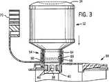
第3図は、レセプタクル中の廃棄物を処理するよう、レセプタクルの蓋上で作動位置にあるリザーバシステムの部分断面図である。
第4図は、設定および接続する直前の、組み立てたリザーバシステムおよび使い捨てレセプタクルの斜視図である。
第5図は、安全クリップを外した状態で、レセプタクル上の用意が調った位置のリザーバシステムの斜視図である。
第6図は、システムを作動させ、廃棄物を処理した後の、リザーバシステムの斜視図である。
発明の詳細な説明
本発明には様々な実施の形態が考えられるが、本明細書の開示は本発明の例証と見なされ、例証された特定の実施形態に本発明を限定するものではないと理解し、現在の好ましい実施形態を図面で図示し、以下で説明する。
第1図を参照すると、本発明の原理を具体化した廃棄物処理リザーバシステム10の分解図が図示されている。システムは、一体型の底部14、側壁16および肩18を含むほぼ閉じたコンテナ12を含む。円筒形の首部分20が肩から延在し、開放口22を含む。第一外周リップ24および第二平行外周リップ26が、首部分上に配置されている。コンテナ12は、高密度ポリエチレン(HDP)などの適切な熱可塑性樹脂からブロー成形されてもよい。
ディフューザキャップ30は、開放端34および実質的に閉じた端36を有する円筒形壁部分32を含む。閉端は、ディフューザキャップの開放端を向いた頂部を有する一体型の円錐形端壁38によって規定される。複数の開口部40が、ディフューザキャップの円筒形側壁の下半分を通って半径方向に延び、ディフューザキャップの内部からの通路を提供する。円筒形側壁は、開口部間で、内部縦リブ42によって強化することができる。リブは、廃棄物処理材を適切な開口部を通って円錐形端壁の表面を下方向に案内するガイドとしても機能する。
ディフューザキャップ30は、ディフューザキャップの開放端に第一内周溝46、ディフューザキャップの中間に第二内周溝48も含む。ディフューザの円筒形壁の外面に、わずかに隆起した外周リップ50が配置される。ディフューザキャップは、ポリプロピレンなどの熱可塑性樹脂で射出成形することが好ましい。
ディフューザキャップの第一および第二内周溝46および48は、ディフューザキャップがコンテナの首部分に入れ子式に対合すると、コンテナ12の首部分の第一および第二外周リップ24および26と対合する。ディフューザキャップ30とコンテナ12とがリザーバシステムの組立中に互いに対して容易に滑り嵌合するが、キャップとコンテナとの分離には協力に抵抗するよう、リップおよび溝は構成される。
二重壁スリーブ54も、廃棄物処理リザーバシステムの第三構成要素として、HPDなどの適切な熱可塑性樹脂から射出成形される。二重壁スリーブは、内壁56および外壁58を含む。2枚の壁はほぼ同心円であるが、ぴったりテーパ嵌合して円筒形フランジと対合密封するよう、少なくとも一方の壁は、スリーブの軸に対してわずかな角度を有することが好ましい。
内壁の内面60は、キャップがスリーブに対して第一位置にあるときに、ディフューザキャップの開口部40も密封状態で覆う。スリーブの内面は、浅い上部内面溝64および浅い下部内面溝66を有する。スリーブに対するディフューザキャップの第一位置は、ディフューザキャップのわずかに隆起した外周リップ50が、スリーブの浅い上部内面溝64内にあるときに規定される。二重壁スリーブは、内外壁間に開放チャネル62も含む。内壁56および外壁58は、開放チャネルがレセプタクルの蓋にある注入口の延長円筒形フランジ部分88と入れ子式に嵌合するよう構成される。
二重壁スリーブ54は、つなぎ接続部72によってスリーブに一体接続される安全クリップ70を含む。クリップはC字形であり、したがってクリップの端部は半円よりわずかに長く延びる。クリップ半円の内径は、ディフューザキャップ30の外径とサイズが等しく、したがってプラスチック製クリップのアームは、ディフューザの周囲に弾性嵌合する。クリップ70の軸長は、ディフューザキャップの上半分の軸長、つまり隆起した外側リップ50から閉端36までの長さと等しい。クリップがディフューザキャップの周囲に嵌合すると、クリップの軸長によって、ディフューザキャップの複数の開放口40は、確実に、二重壁スリーブの内壁の内面60によって覆われたままである。
使い捨てレセプタクル80は、硬質蓋82と、蓋に密封されて、蓋から下がる軟質ライナ84とを含む。ライナおよび蓋はともに、たとえば1、2または3リットルの容量を有する密封チャンバを規定する。レセプタクルは、吸引式排液システムによって吸引された廃液を保持する。
蓋は、円筒形フランジ88によって規定されて着脱可能なキャップ90によって密閉された注ぎ口86を含む。円筒形フランジも、二重壁スリーブの内壁56と外壁58との間にテーパ嵌合するため、テーパをつけてよい。二重壁スリーブの内壁と外壁との間のチャネル62は、チャネルの開放端がコンテナ12から離れた方向を向くよう、配向される。チャネルによって、廃棄物処理剤リザーバシステムは、レセプタクルの注入口上に容易にかつ密封状態に摺動することができる。
次に、吸引式排液システムによって使い捨てレセプタクルに収集された廃棄物の処理に、本発明を使用することについて説明する。第4図を参照すると、組み立てた廃棄物処理剤リザーバシステム10は、二重壁スリーブ54の開放チャネルが注入口86の円筒形フランジ88に面するよう配向されている。廃棄物処理剤リザーバ10は、システムの時期尚早または偶発的な作動を防止するよう、ディフューザの上半分に配置された安全クリップ70で、レセプタクルの使い捨ての蓋およびライナに接続される。廃棄物処理剤リザーバ10が所定の位置にしっかりある状態で(第5図)、クリップ70をディフューザキャップから外す。第3図および第6図から分るように、リザーバのコンテナの底部14をかるく押すと、ディフューザキャップが二重壁スリーブの第二位置に摺動する。
第二位置は、ディフューザキャップのわずかに隆起した外周リップ50が二重壁スリーブの浅い上部内面溝64から浅い下部内面溝66へ移動する、と規定される。この移動の結果は、第3図に図示され、これによってディフューザキャップの複数の開放口40が、二重壁スリーブ54の内壁の内面60より先に移動する。第二位置で、リザーバ10内にある廃棄物処理剤の通路は、コンテナ12の内部からレセプタクルのチャンバへと開く。
さらに、処理剤がチャンバ内へと落ちる際に、ディフューザキャップの円錐形端壁38が、廃液全体に廃棄物処理剤を分散させる。処理剤がゲル化剤、固化剤、殺菌剤、または上記のいずれかの組合せであっても、この分散が、より高速かつ効果的な廃棄物の処理を促進する。
二重壁スリーブ54およびディフューザキャップの端壁38が、注入口の口キャップ90と密封状態で置き換わり、したがって外科処置の開始前に、廃棄物処理剤リザーバシステムを、使い捨てレセプタクル上に予め配置することができる。スリーブおよび端壁による密封で、吸引排液システムは、所定の位置に予め配置された廃棄物処理剤リザーバとともに作動し、ライナ内に廃棄物を収集することができる。したがって、使い捨てレセプタクルが容量に達したら、外科助手は迅速に安全クリップ70を外し、コンテナの底部14を押下してシステムを作動させることができる。廃棄物処理剤が、潜在的に有害な廃液に迅速かつタイムリーに作用する。これによって、使い捨てレセプタクルを交換するか、移動させることが望ましい場合に、廃液が未処理の状態であるという危険が軽減される。
上記から、本発明の斬新な概念の真の精神および範囲から逸脱することなく、無数の修正および変形が実行できることが理解される。本明細書の開示は、広く理解され、本明細書で開示された特定の実施形態については、何の制約も意図されず、想定されない。開示は、添付の請求の範囲によって、請求の範囲に含まれるすべての修正を対象とするものとする。FIELD OF THE INVENTION The present invention relates generally to a reservoir containing a waste treatment agent for use with a disposable waste receptacle used with an associated suction drainage system, and more particularly to a disposable waste. Can be placed on top of a receptacle to treat collected waste using an associated suction drainage system, thus pre-positioning the reservoir prior to the suction drainage procedure and operating after the procedure It is related with the reservoir which can do.
BACKGROUND OF THE INVENTION Aspirated drainage systems commonly used today have disposable receptacles, such as rigid containers or soft liners, that collect waste (i.e. body fluid) from surgical and other patient procedures. A fluid connection line connects the disposable receptacle to the patient's body. Another line connects the receptacle to the suction source. Inhaled waste is often highly infectious and exposure through spills or leaks from receptacles must be avoided. Spills and leaks are most common during the transfer or exchange of receptacles.
Therefore, it is desirable to treat the waste prior to disposal by providing an absorbent, gelling agent, or disinfectant to reduce the possibility of exposure. Some known waste treatment systems have a reservoir containing a waste treatment agent permanently and / or integrally attached to a disposable receptacle of a suction drainage system. A permanent reservoir will limit the ability to use different waste treatment agents in different situations. Alternatively, a flexible mounting system is disclosed in U.S. Patent Application No. 269,496, entitled "Suction Drainage Gelation", assigned to the assignee of the present invention Abbott Laboratories and sold by that assignee. . One limitation of the flexible attached waste treatment system disclosed above is that the system cannot be set up prior to the waste aspirated drainage procedure. Accordingly, the surgical assistant must set up and operate the waste disposal system during the surgical procedure or after the surgical procedure is completed. Small surgical teams may not be able to provide extra personnel to begin this waste treatment during or immediately after the surgical procedure. Thus, dangerous fluids are left untreated and may pose a potential hazard for some time after the end of the surgical procedure.
The waste treatment system of the present invention is specifically configured to facilitate rapid, efficient and convenient treatment of waste liquid during or after a surgical procedure. Prior to the start of surgery, a reservoir containing a waste treatment agent can be placed in a position to treat the waste and can be activated as soon as the disposable receptacle is full. Thus, receptacles containing waste can be processed immediately after reaching full, thus reducing the possibility of contamination.
SUMMARY OF THE INVENTION The present invention is directed to a waste treatment reservoir for treating waste collected using an associated suction system. A disposable receptacle connected to an associated suction system includes a sealed chamber such as a liner and a lid with a spout. The waste treatment reservoir includes a closed container with an open mouth for storing waste treatment agents. A cylindrical wall forms a diffuser cap and has an open end and a generally closed end. The closed end has a plurality of openings that open radially through the cylindrical wall. The open end of the cylindrical diffuser cap nests the opening of the treatment agent container. The reservoir system further includes a double wall sleeve having an inner wall and a generally concentric outer wall that attaches the combined diffuser cap and drug container to the lid opening of the disposable receptacle. The inner surface of the inner wall of the sleeve seals the radial opening of the cap in a sealed manner when the diffuser cap is in a first position relative to the sleeve. The outer surface of the inner wall and the outer wall can be mated with the cover opening of the receptacle so that the diffuser cap is slidable to the second position of the double wall sleeve. In the second position, the radial opening moves axially beyond the inner surface of the inner wall of the sleeve. This allows an open path for the waste treatment agent to flow from inside the drug reservoir to the chamber of the disposable receptacle. The waste treatment reservoir of the present invention is configured to set up the system prior to the surgical procedure and can be easily activated immediately after the surgical procedure, thus treating hazardous waste immediately and efficiently.
Other features and advantages of the system of the present invention will be readily apparent from the following detailed description, the accompanying drawings, and the claims.
[Brief description of the drawings]
FIG. 1 is an exploded partial cross-sectional view of components of a waste treatment agent reservoir system of the present invention and a lid of a disposable receptacle.
FIG. 2 is a partial cross-sectional view of the reservoir system in a ready position on the receptacle lid.
FIG. 3 is a partial cross-sectional view of the reservoir system in an operative position on the receptacle lid to treat waste in the receptacle.
FIG. 4 is a perspective view of the assembled reservoir system and disposable receptacle just prior to setup and connection.
FIG. 5 is a perspective view of the reservoir system in a ready position on the receptacle with the safety clip removed.
FIG. 6 is a perspective view of the reservoir system after operating the system and disposing of the waste.
DETAILED DESCRIPTION OF THE INVENTION While the invention is susceptible to various embodiments, the disclosure herein is considered as illustrative of the invention and limits the invention to the specific embodiments illustrated. It is understood that this is not the case and the presently preferred embodiment is illustrated in the drawings and described below.
Referring to FIG. 1, an exploded view of a waste
The
The
The first and second inner
The
The
The
The lid includes a
Next, the use of the present invention for the treatment of waste collected in a disposable receptacle by a suction drainage system will be described. Referring to FIG. 4, the assembled waste treatment
The second position is defined as the slightly raised
In addition, the
The
From the foregoing, it will be appreciated that numerous modifications and variations can be made without departing from the true spirit and scope of the inventive concepts of the present invention. The disclosure herein is well understood and no limitation is intended or envisioned for the specific embodiments disclosed herein. The disclosure is intended to cover all modifications contained within the scope of the appended claims.
Claims (7)
Translated fromJapanese廃棄物処理剤を貯蔵する開放口付きの閉じた容器と、
開放端部分およびほぼ閉じた端部分を有する円筒形のディフューザキャップとを備え、閉端部分は複数の半径方向開口部を有して、開放端部分は、処理済コンテナの開放口に入れ子式に対合し、さらに、
組み合わせたディフューザキャップと処理剤コンテナとをレセプタクルの蓋の口に取り付けるための内壁と、これとおおむね同心円の外壁とを有する二重壁スリーブを備え、キャップがスリーブに対して第一位置にあるときは、内壁の内面が、ディフューザキャップの半径方向開口部を密封状態で覆い、内壁の外面と外壁が、レセプタクルの蓋の口と密封状態で嵌合し、したがってディフューザキャップは二重壁スリーブの第二位置へ、軸方向に摺動可能であり、半径方向開口部が、スリーブの内壁の内面を越え、したがって廃棄物処理剤の通路が薬剤コンテナからレセプタクルのチャンバへと開くリザーバシステム。A reservoir system for processing waste collected using an associated suction system into a disposable receptacle having a chamber and a spouted lid,
A closed container with an open mouth for storing the waste treatment agent;
A cylindrical diffuser cap having an open end portion and a generally closed end portion, the closed end portion having a plurality of radial openings, the open end portion being nested within an open port of the treated container Pair, and
A double wall sleeve having an inner wall for attaching the combined diffuser cap and treatment agent container to the receptacle lidmouth and a generally concentric outer wall when the cap is in a first position relative to the sleeve; The inner surface of the inner wall covers the radial opening of the diffuser cap in a sealed manner, and the outer surface of the inner wall and the outer wall fit in a sealed manner with the mouth of the lid of the receptacle, so that the diffuser cap is A reservoir system that is slidable axially into two positions, with a radial opening beyond the inner surface of the inner wall of the sleeve, thus opening the waste treatment agent passageway from the drug container to the receptacle chamber.
Applications Claiming Priority (3)
| Application Number | Priority Date | Filing Date | Title |
|---|---|---|---|
| US08/413,569US5543042A (en) | 1995-03-30 | 1995-03-30 | Waste agent reservoir for suction drainage system |
| US08/413,569 | 1995-03-30 | ||
| PCT/US1996/004191WO1996030061A1 (en) | 1995-03-30 | 1996-03-27 | Waste agent reservoir for suction drainage system |
Publications (2)
| Publication Number | Publication Date |
|---|---|
| JP2002516578A JP2002516578A (en) | 2002-06-04 |
| JP3707561B2true JP3707561B2 (en) | 2005-10-19 |
Family
ID=23637742
Family Applications (1)
| Application Number | Title | Priority Date | Filing Date |
|---|---|---|---|
| JP52961896AExpired - Fee RelatedJP3707561B2 (en) | 1995-03-30 | 1996-03-27 | Waste drug reservoir for suction-type drainage system |
Country Status (11)
| Country | Link |
|---|---|
| US (1) | US5543042A (en) |
| EP (1) | EP0827414B1 (en) |
| JP (1) | JP3707561B2 (en) |
| AT (1) | ATE225193T1 (en) |
| AU (1) | AU701564B2 (en) |
| CA (1) | CA2216956C (en) |
| DE (1) | DE69624108T2 (en) |
| DK (1) | DK0827414T3 (en) |
| ES (1) | ES2186776T3 (en) |
| PT (1) | PT827414E (en) |
| WO (1) | WO1996030061A1 (en) |
Families Citing this family (46)
| Publication number | Priority date | Publication date | Assignee | Title |
|---|---|---|---|---|
| DE19723197C2 (en)* | 1997-06-03 | 1999-07-29 | Braun Melsungen Ag | Suction device for body fluids |
| FR2851912B1 (en)* | 2003-03-03 | 2005-05-13 | Optis France Sa | UNIFORM POWER CONNECTOR FOR DELIVERY DEVICES OF ACTIVE PRINCIPLES |
| JP2010275019A (en)* | 2009-04-30 | 2010-12-09 | Sanyo Chem Ind Ltd | Joint |
| US10226376B2 (en) | 2014-03-19 | 2019-03-12 | Purewick Corporation | Apparatus and methods for receiving discharged urine |
| US11376152B2 (en) | 2014-03-19 | 2022-07-05 | Purewick Corporation | Apparatus and methods for receiving discharged urine |
| US11806266B2 (en) | 2014-03-19 | 2023-11-07 | Purewick Corporation | Apparatus and methods for receiving discharged urine |
| US10390989B2 (en) | 2014-03-19 | 2019-08-27 | Purewick Corporation | Apparatus and methods for receiving discharged urine |
| US10952889B2 (en) | 2016-06-02 | 2021-03-23 | Purewick Corporation | Using wicking material to collect liquid for transport |
| CN104116635B (en)* | 2014-08-01 | 2016-08-03 | 李珊珊 | A kind of medical rubber stopper bottle |
| FI128232B (en) | 2014-08-07 | 2020-01-15 | Serres Oy | Accessory part |
| US10973678B2 (en) | 2016-07-27 | 2021-04-13 | Purewick Corporation | Apparatus and methods for receiving discharged urine |
| US10376406B2 (en) | 2016-07-27 | 2019-08-13 | Purewick Corporation | Male urine collection device using wicking material |
| JP2020510464A (en) | 2017-01-31 | 2020-04-09 | ピュアウィック コーポレイション | Apparatus and method for receiving excreted urine |
| KR102492111B1 (en) | 2018-05-01 | 2023-01-27 | 퓨어윅 코포레이션 | Fluid Collection Devices and Methods of Using The Same |
| WO2019212952A1 (en) | 2018-05-01 | 2019-11-07 | Purewick Corporation | Fluid collection devices, related systems, and related methods |
| WO2019212950A1 (en) | 2018-05-01 | 2019-11-07 | Purewick Corporation | Fluid collection devices, related systems, and related methods |
| JP7093851B2 (en) | 2018-05-01 | 2022-06-30 | ピュアウィック コーポレイション | Fluid collecting clothing |
| KR102513810B1 (en) | 2018-05-01 | 2023-03-24 | 퓨어윅 코포레이션 | Fluid collection devices, systems and methods |
| CN108853616A (en)* | 2018-06-25 | 2018-11-23 | 河南驼人贝斯特医疗器械有限公司 | The negative pressure drainage device that achievable waste liquid solidifies at any time |
| WO2020256865A1 (en) | 2019-06-21 | 2020-12-24 | Purewick Corporation | Fluid collection devices including a base securement area, and related systems and methods |
| US12329364B2 (en) | 2019-07-19 | 2025-06-17 | Purewick Corporation | Fluid collection devices including at least one shape memory material |
| JP7269851B2 (en)* | 2019-09-20 | 2023-05-09 | 大研医器株式会社 | Waste liquid storage container, waste liquid reservoir provided with the same, and waste liquid suction system |
| US12350190B2 (en) | 2020-01-03 | 2025-07-08 | Purewick Corporation | Urine collection devices having a relatively wide portion and an elongated portion and related methods |
| ES2969642T3 (en) | 2020-04-10 | 2024-05-21 | Purewick Corp | Fluid collection assemblies that include one or more leak prevention features |
| EP3904230A1 (en)* | 2020-04-30 | 2021-11-03 | Suppsolution GmbH | Portion container, container mixing system and method of use therefor |
| US12048643B2 (en) | 2020-05-27 | 2024-07-30 | Purewick Corporation | Fluid collection assemblies including at least one inflation device and methods and systems of using the same |
| USD967409S1 (en) | 2020-07-15 | 2022-10-18 | Purewick Corporation | Urine collection apparatus cover |
| US20220047410A1 (en) | 2020-08-11 | 2022-02-17 | Purewick Corporation | Fluid collection assemblies defining waist and leg openings |
| US12156792B2 (en) | 2020-09-10 | 2024-12-03 | Purewick Corporation | Fluid collection assemblies including at least one inflation device |
| US11801186B2 (en) | 2020-09-10 | 2023-10-31 | Purewick Corporation | Urine storage container handle and lid accessories |
| US12042423B2 (en) | 2020-10-07 | 2024-07-23 | Purewick Corporation | Fluid collection systems including at least one tensioning element |
| US12208031B2 (en) | 2020-10-21 | 2025-01-28 | Purewick Corporation | Adapters for fluid collection devices |
| US12257174B2 (en) | 2020-10-21 | 2025-03-25 | Purewick Corporation | Fluid collection assemblies including at least one of a protrusion or at least one expandable material |
| US12048644B2 (en) | 2020-11-03 | 2024-07-30 | Purewick Corporation | Apparatus for receiving discharged urine |
| US12070432B2 (en) | 2020-11-11 | 2024-08-27 | Purewick Corporation | Urine collection system including a flow meter and related methods |
| US12245967B2 (en) | 2020-11-18 | 2025-03-11 | Purewick Corporation | Fluid collection assemblies including an adjustable spine |
| US12268627B2 (en) | 2021-01-06 | 2025-04-08 | Purewick Corporation | Fluid collection assemblies including at least one securement body |
| CA3162613A1 (en) | 2021-01-19 | 2022-07-19 | Purewick Corporation | Variable fit fluid collection devices, systems, and methods |
| US12178735B2 (en) | 2021-02-09 | 2024-12-31 | Purewick Corporation | Noise reduction for a urine suction system |
| EP4274524B1 (en) | 2021-02-26 | 2024-08-28 | Purewick Corporation | A male fluid collection device configured as a male urine collection device |
| US11938054B2 (en) | 2021-03-10 | 2024-03-26 | Purewick Corporation | Bodily waste and fluid collection with sacral pad |
| US12029677B2 (en) | 2021-04-06 | 2024-07-09 | Purewick Corporation | Fluid collection devices having a collection bag, and related systems and methods |
| US12233003B2 (en) | 2021-04-29 | 2025-02-25 | Purewick Corporation | Fluid collection assemblies including at least one length adjusting feature |
| US12251333B2 (en) | 2021-05-21 | 2025-03-18 | Purewick Corporation | Fluid collection assemblies including at least one inflation device and methods and systems of using the same |
| US12324767B2 (en) | 2021-05-24 | 2025-06-10 | Purewick Corporation | Fluid collection assembly including a customizable external support and related methods |
| US12150885B2 (en) | 2021-05-26 | 2024-11-26 | Purewick Corporation | Fluid collection system including a cleaning system and methods |
Family Cites Families (14)
| Publication number | Priority date | Publication date | Assignee | Title |
|---|---|---|---|---|
| US3404811A (en)* | 1966-12-02 | 1968-10-08 | Cernei Jose | Container for maintaining in separate condition liquids which are to be mixed together and which may be manipulated to commingle such liquids |
| US4024991A (en)* | 1975-11-28 | 1977-05-24 | George Noblit Tyson | Imparter to provide silver to water supplies |
| US4145291A (en)* | 1976-09-27 | 1979-03-20 | Foremost-Mckesson, Inc. | Disinfecting means within a water dispenser |
| US5391351A (en)* | 1987-10-07 | 1995-02-21 | Kaufman; Jack W. | Body waste fluids solidification system |
| FR2630997B1 (en)* | 1988-05-04 | 1990-09-14 | Tecnoma | DEVICE FOR INTRODUCING A DOSED QUANTITY OF A PRODUCT WITHIN A SPEAKER |
| DE69008600T2 (en)* | 1989-03-30 | 1994-08-25 | Abbott Lab | Suction device with a device for preventing infection. |
| US5405526A (en)* | 1990-06-21 | 1995-04-11 | Sutera; Carl M. | Bottle water disinfectant system |
| FR2667049B1 (en)* | 1990-09-26 | 1994-07-08 | Kerplas Snc | DOUBLE BODY BOTTLE. |
| US5139666A (en)* | 1991-01-04 | 1992-08-18 | Domotechnica Canada, Inc. | Bottle and filter |
| US5240620A (en)* | 1991-10-01 | 1993-08-31 | Amnon Shalev | Method and apparatus for filtering water |
| JPH0686738U (en)* | 1992-06-16 | 1994-12-20 | 森下ルセル株式会社 | Medical container |
| US5200070A (en)* | 1992-07-20 | 1993-04-06 | Mcmenamin Kevin P | Bottle water filter arrangement |
| IE69360B1 (en)* | 1993-07-01 | 1996-09-04 | Abbott Lab | Gelling treatment for suction drainage system |
| US5417860A (en)* | 1993-08-30 | 1995-05-23 | Filtertek, Inc. | Bottle filter and pouring device |
- 1995
- 1995-03-30USUS08/413,569patent/US5543042A/ennot_activeExpired - Lifetime
- 1996
- 1996-03-27PTPT96912483Tpatent/PT827414E/enunknown
- 1996-03-27AUAU55288/96Apatent/AU701564B2/ennot_activeCeased
- 1996-03-27DKDK96912483Tpatent/DK0827414T3/enactive
- 1996-03-27ESES96912483Tpatent/ES2186776T3/ennot_activeExpired - Lifetime
- 1996-03-27EPEP96912483Apatent/EP0827414B1/ennot_activeExpired - Lifetime
- 1996-03-27DEDE69624108Tpatent/DE69624108T2/ennot_activeExpired - Fee Related
- 1996-03-27WOPCT/US1996/004191patent/WO1996030061A1/enactiveIP Right Grant
- 1996-03-27ATAT96912483Tpatent/ATE225193T1/ennot_activeIP Right Cessation
- 1996-03-27CACA 2216956patent/CA2216956C/ennot_activeExpired - Fee Related
- 1996-03-27JPJP52961896Apatent/JP3707561B2/ennot_activeExpired - Fee Related
Also Published As
| Publication number | Publication date |
|---|---|
| PT827414E (en) | 2003-02-28 |
| EP0827414B1 (en) | 2002-10-02 |
| ES2186776T3 (en) | 2003-05-16 |
| DE69624108T2 (en) | 2003-06-12 |
| AU5528896A (en) | 1996-10-16 |
| US5543042A (en) | 1996-08-06 |
| CA2216956A1 (en) | 1996-10-03 |
| DE69624108D1 (en) | 2002-11-07 |
| JP2002516578A (en) | 2002-06-04 |
| ATE225193T1 (en) | 2002-10-15 |
| EP0827414A1 (en) | 1998-03-11 |
| CA2216956C (en) | 2008-06-10 |
| WO1996030061A1 (en) | 1996-10-03 |
| DK0827414T3 (en) | 2002-12-16 |
| AU701564B2 (en) | 1999-02-04 |
Similar Documents
| Publication | Publication Date | Title |
|---|---|---|
| JP3707561B2 (en) | Waste drug reservoir for suction-type drainage system | |
| US5620428A (en) | Suction canister apparatus and method | |
| US8651531B2 (en) | Method and apparatus for the disposal of waste fluids | |
| US5688255A (en) | Method and apparatus for removing and disposing of body fluids | |
| US5185007A (en) | Suction drainage infection control system | |
| JP3618755B2 (en) | Prevention of overfilling of suction and drainage devices | |
| US5960837A (en) | Suction canister having molded interlocking lid | |
| US6056731A (en) | Suction device for body fluids | |
| US4235344A (en) | Irrigation cap | |
| JP2002516725A (en) | System for storing, mixing and administering drugs | |
| EP1295561A1 (en) | Liquid specimen collection container. | |
| CA2143421A1 (en) | Microporous filtration funnel assembly | |
| JPH02180659A (en) | Liquid dispensing nozzle mechanism | |
| US4357937A (en) | Medical irrigation device | |
| JPH0956810A (en) | Liquid waste treatment equipment | |
| JP2000079162A (en) | Float for liquid waste treatment equipment | |
| US8920394B2 (en) | Suction canister liner and system | |
| JPH11292108A (en) | Closed delivery device | |
| US5672162A (en) | Closure delivery system | |
| JP3049210U (en) | Drug container | |
| CN213526650U (en) | Medical waste liquid collecting cylinder | |
| JP3519425B2 (en) | Liquid waste suction treatment method and treatment apparatus | |
| JP2024518789A (en) | Liquid dispenser and protective cap for liquid dispenser |
Legal Events
| Date | Code | Title | Description |
|---|---|---|---|
| A131 | Notification of reasons for refusal | Free format text:JAPANESE INTERMEDIATE CODE: A131 Effective date:20050111 | |
| A711 | Notification of change in applicant | Free format text:JAPANESE INTERMEDIATE CODE: A711 Effective date:20050208 | |
| A601 | Written request for extension of time | Free format text:JAPANESE INTERMEDIATE CODE: A601 Effective date:20050405 | |
| A521 | Request for written amendment filed | Free format text:JAPANESE INTERMEDIATE CODE: A523 Effective date:20050509 | |
| A602 | Written permission of extension of time | Free format text:JAPANESE INTERMEDIATE CODE: A602 Effective date:20050530 | |
| TRDD | Decision of grant or rejection written | ||
| A01 | Written decision to grant a patent or to grant a registration (utility model) | Free format text:JAPANESE INTERMEDIATE CODE: A01 Effective date:20050719 | |
| A61 | First payment of annual fees (during grant procedure) | Free format text:JAPANESE INTERMEDIATE CODE: A61 Effective date:20050727 | |
| R150 | Certificate of patent or registration of utility model | Free format text:JAPANESE INTERMEDIATE CODE: R150 | |
| FPAY | Renewal fee payment (event date is renewal date of database) | Free format text:PAYMENT UNTIL: 20090812 Year of fee payment:4 | |
| FPAY | Renewal fee payment (event date is renewal date of database) | Free format text:PAYMENT UNTIL: 20100812 Year of fee payment:5 | |
| FPAY | Renewal fee payment (event date is renewal date of database) | Free format text:PAYMENT UNTIL: 20100812 Year of fee payment:5 | |
| FPAY | Renewal fee payment (event date is renewal date of database) | Free format text:PAYMENT UNTIL: 20110812 Year of fee payment:6 | |
| FPAY | Renewal fee payment (event date is renewal date of database) | Free format text:PAYMENT UNTIL: 20120812 Year of fee payment:7 | |
| FPAY | Renewal fee payment (event date is renewal date of database) | Free format text:PAYMENT UNTIL: 20130812 Year of fee payment:8 | |
| LAPS | Cancellation because of no payment of annual fees |