JP3705816B2 - Image-guided biopsy device and method with improved imaging - Google Patents
Image-guided biopsy device and method with improved imagingDownload PDFInfo
- Publication number
- JP3705816B2 JP3705816B2JP53123996AJP53123996AJP3705816B2JP 3705816 B2JP3705816 B2JP 3705816B2JP 53123996 AJP53123996 AJP 53123996AJP 53123996 AJP53123996 AJP 53123996AJP 3705816 B2JP3705816 B2JP 3705816B2
- Authority
- JP
- Japan
- Prior art keywords
- tissue mass
- biopsy instrument
- tip
- tissue
- support
- Prior art date
- Legal status (The legal status is an assumption and is not a legal conclusion. Google has not performed a legal analysis and makes no representation as to the accuracy of the status listed.)
- Expired - Fee Related
Links
Images


Classifications
- A—HUMAN NECESSITIES
- A61—MEDICAL OR VETERINARY SCIENCE; HYGIENE
- A61B—DIAGNOSIS; SURGERY; IDENTIFICATION
- A61B8/00—Diagnosis using ultrasonic, sonic or infrasonic waves
- A61B8/42—Details of probe positioning or probe attachment to the patient
- A61B8/4272—Details of probe positioning or probe attachment to the patient involving the acoustic interface between the transducer and the tissue
- A61B8/4281—Details of probe positioning or probe attachment to the patient involving the acoustic interface between the transducer and the tissue characterised by sound-transmitting media or devices for coupling the transducer to the tissue
- A—HUMAN NECESSITIES
- A61—MEDICAL OR VETERINARY SCIENCE; HYGIENE
- A61B—DIAGNOSIS; SURGERY; IDENTIFICATION
- A61B17/00—Surgical instruments, devices or methods
- A61B17/34—Trocars; Puncturing needles
- A61B17/3403—Needle locating or guiding means
- A—HUMAN NECESSITIES
- A61—MEDICAL OR VETERINARY SCIENCE; HYGIENE
- A61B—DIAGNOSIS; SURGERY; IDENTIFICATION
- A61B8/00—Diagnosis using ultrasonic, sonic or infrasonic waves
- A61B8/08—Clinical applications
- A61B8/0833—Clinical applications involving detecting or locating foreign bodies or organic structures
- A61B8/0841—Clinical applications involving detecting or locating foreign bodies or organic structures for locating instruments
- A—HUMAN NECESSITIES
- A61—MEDICAL OR VETERINARY SCIENCE; HYGIENE
- A61B—DIAGNOSIS; SURGERY; IDENTIFICATION
- A61B90/00—Instruments, implements or accessories specially adapted for surgery or diagnosis and not covered by any of the groups A61B1/00 - A61B50/00, e.g. for luxation treatment or for protecting wound edges
- A61B90/10—Instruments, implements or accessories specially adapted for surgery or diagnosis and not covered by any of the groups A61B1/00 - A61B50/00, e.g. for luxation treatment or for protecting wound edges for stereotaxic surgery, e.g. frame-based stereotaxis
- A61B90/14—Fixators for body parts, e.g. skull clamps; Constructional details of fixators, e.g. pins
- A61B90/17—Fixators for body parts, e.g. skull clamps; Constructional details of fixators, e.g. pins for soft tissue, e.g. breast-holding devices
- A—HUMAN NECESSITIES
- A61—MEDICAL OR VETERINARY SCIENCE; HYGIENE
- A61B—DIAGNOSIS; SURGERY; IDENTIFICATION
- A61B10/00—Instruments for taking body samples for diagnostic purposes; Other methods or instruments for diagnosis, e.g. for vaccination diagnosis, sex determination or ovulation-period determination; Throat striking implements
- A61B10/02—Instruments for taking cell samples or for biopsy
- A61B10/0233—Pointed or sharp biopsy instruments
- A—HUMAN NECESSITIES
- A61—MEDICAL OR VETERINARY SCIENCE; HYGIENE
- A61B—DIAGNOSIS; SURGERY; IDENTIFICATION
- A61B90/00—Instruments, implements or accessories specially adapted for surgery or diagnosis and not covered by any of the groups A61B1/00 - A61B50/00, e.g. for luxation treatment or for protecting wound edges
- A61B90/36—Image-producing devices or illumination devices not otherwise provided for
- A61B90/37—Surgical systems with images on a monitor during operation
- A61B2090/378—Surgical systems with images on a monitor during operation using ultrasound
- A—HUMAN NECESSITIES
- A61—MEDICAL OR VETERINARY SCIENCE; HYGIENE
- A61B—DIAGNOSIS; SURGERY; IDENTIFICATION
- A61B2562/00—Details of sensors; Constructional details of sensor housings or probes; Accessories for sensors
- A61B2562/16—Details of sensor housings or probes; Details of structural supports for sensors
- A61B2562/168—Fluid filled sensor housings
- A—HUMAN NECESSITIES
- A61—MEDICAL OR VETERINARY SCIENCE; HYGIENE
- A61B—DIAGNOSIS; SURGERY; IDENTIFICATION
- A61B90/00—Instruments, implements or accessories specially adapted for surgery or diagnosis and not covered by any of the groups A61B1/00 - A61B50/00, e.g. for luxation treatment or for protecting wound edges
- A61B90/10—Instruments, implements or accessories specially adapted for surgery or diagnosis and not covered by any of the groups A61B1/00 - A61B50/00, e.g. for luxation treatment or for protecting wound edges for stereotaxic surgery, e.g. frame-based stereotaxis
- A61B90/11—Instruments, implements or accessories specially adapted for surgery or diagnosis and not covered by any of the groups A61B1/00 - A61B50/00, e.g. for luxation treatment or for protecting wound edges for stereotaxic surgery, e.g. frame-based stereotaxis with guides for needles or instruments, e.g. arcuate slides or ball joints
Landscapes
- Health & Medical Sciences (AREA)
- Life Sciences & Earth Sciences (AREA)
- Surgery (AREA)
- Medical Informatics (AREA)
- Veterinary Medicine (AREA)
- Pathology (AREA)
- Nuclear Medicine, Radiotherapy & Molecular Imaging (AREA)
- Engineering & Computer Science (AREA)
- Biomedical Technology (AREA)
- Heart & Thoracic Surgery (AREA)
- Public Health (AREA)
- Molecular Biology (AREA)
- General Health & Medical Sciences (AREA)
- Animal Behavior & Ethology (AREA)
- Physics & Mathematics (AREA)
- Biophysics (AREA)
- Radiology & Medical Imaging (AREA)
- Acoustics & Sound (AREA)
- Neurosurgery (AREA)
- Oral & Maxillofacial Surgery (AREA)
- Ultra Sonic Daignosis Equipment (AREA)
- Apparatus For Radiation Diagnosis (AREA)
Description
Translated fromJapanese発明の分野
本発明は、生物学的組織の生検を行うための装置および方法に関し、より詳細には、超音波イメージングでガイドしながら生物学的組織の生検を行うことに関する。
発明の背景
例えば放射線撮影(radiographic)および断層撮影(sonographic)技術を用いることにより、悪性と疑われる腫瘍塊を同定するための装置および方法が知られている。典型的には、そのような組織塊に対して次に生検を行うことにより、悪性の状態あるいは程度を決定してさらなる治療コースを決定する。例えば、乳房X線像の病変を含むことが疑われる領域を生検することにより、病変が悪性であるか良性であるかを決定し、もし悪性であれば、悪性の程度に応じた治療コース、例えば乳房切除術、放射線治療または化学療法などを決定する。
従来公知の生検方法は、21ゲージの皮下注射針を用いた微細針吸引や、自動化生検銃に実装された14ゲージの針を用いたラージコア生検などの最小侵襲的技術から、病変部を外科的に切除する開手順にわたる。最小侵襲的技術は、外科的切除よりも、速く安価であり、患者に対して安全かつ傷害性が低いために、幅広く受け入れられるようになってきている。
しかし、従来公知の最小侵襲的生検技術に共通する問題は、病変周囲の健常組織ではなく、病変と疑わしい部分からの組織サンプルを、生検針が本当に得ることができるようにすることである。生検針の軌跡が病変と疑わしい領域に入っていくことを確実にするための従来公知の技術は、例えば、Fornageら、”Ultrasound-Guided Needle Biopsy of The Breast And Other Interventional Procedures”、Radiologica Clinics of North America、Vol.30、No.1(1992年1月)、Fornageら、”Breast Masses: US-Guided Fine Needle Aspiration Biopsy”Radiology、162: 409-414(1987年2月)、Parkerら、”US-Guided Automated Large-Core Breast Biopsy”、Radiology、187: 507-511(1993年5月)ならびに、ParkerおよびJobe、”Large-Core Breast Biopsy Offers Reliable Diagnosis”,Diagnostic Imagingからの再版(1990年10月)に記載がある。
上記文献は、フリーハンドによる超音波技術を記載しており、生検針の病変と疑わしい部分への挿入を、一方の手に直線配列状の超音波トランスデューサを持ちながら他方の手で針を組織に挿入することにより行っている。特に、超音波トランスデューサを疑わしい塊の正中線の上方に保持し、次に針(または自動化生検銃の針)をトランスデューサの基部近辺の組織に挿入することにより、針の先端が超音波スキャン中に現れるようにする。さらに、生検銃を用いる際には、使用中に生検銃を安定させたり、超音波トランスデューサを保持するために追加的な人手が必要になり得る。
FornageらおよびPakerらの文献に記載されるように、病変と疑わしい部分が患者の胸壁近傍、あるいは補綴物(prothesis)の近傍に位置するときには、フリーハンド技術では困難になる。これらの文献はまた、フリーハンド技術を使用する際の医師(practitioner)の技術レベルによって、得られる結果が劇的に影響され得ることを、強調している。上述の文献は全て、超音波トランスデューサに接続され得る生検針ガイドの使用を却下している。なぜなら、ガイドは、良好な結果を得るために必要なフレキシビリティーおよび操作性の邪魔になるからである。
ParkerおよびJobeの文献はまた、定位(stereotactic)乳房X線撮影生検システムを記載している。このようなシステムにおいては、異なる角度からの胸部組織のX線イメージを2つ撮ることにより、病変の座標を計算することを可能にする。生検針−−典型的には生検台に取り付けられた剛性のハウジングに実装された自動化生検銃(例えば、ジョージア州Covington、Bard DivisionのC.R. Bard. Inc.から入手可能なBiopyt)−−を、計算された座標に移動してアクチュエートする。さらに2つの胸部組織X線を撮ることにより、針が実際に病変と疑わしい領域をサンプルしたか否かを確認する。
ParkerおよびJobeの文献はアド・オン型定位システムの欠点を記載している。すなわち、胸部が移動することにより、以前になされた立体計算(stereo calculation)が無駄になってしまう可能性である。この文献はまた、コロラド州ThorntonのFischer Imagin Corporationから販売されているMammotest systemによりアド・オン型定位システムの欠点のいくつかが克服されるが、かなりのコスト差がでてしまうことが記載されている。
しかし、全ての定位システムに共通の欠点は、組織のX線写真を複数撮る必要のために、健康を害する恐れのあるイオン化照射に、組織を曝してしまうことである。これらのシステムはまた、針軌跡のリアルタイムでのイメージングを提供し得ないため、ParkerおよびJobeの文献に記載されているように、胸部組織が途中で動くことにより、計算された座標が無駄になってしまい、誤解を招くような生検サンプルが得られてしまう可能性がある。実際、臨床医は、生検針が意図されたターゲットから外れてしまったことに、フォローアップとしての定位像を撮るまで気づかないのである。
また、生検針の軌跡を固定する目的で、固定されたハウジング中に生検針が固定されているために、定位システムでは、ターゲット組織に対して生検針の移動の自由がない。結果として、組織を十分に特徴付けるためには、何度か針を抜き差しすることが必要になる。
上述の従来公知の方法および装置の大きな欠点は、生検針の胸部表面から腫瘍あるいは病変と疑わしい領域への正しい軌跡を、臨床医がリアルタイムで評価することができないことに起因するものである。フリーハンドの超音波スキャニングでガイドされている場合でさえも、病変と疑わしい部分が回収できたという確信のレベルを高めるためには、臨床医は典型的には生検針を10〜15回以上抜き差ししなければならない。そして、針吸引サンプルの各々を別々にテストしなければならず、手順の総コストが大きく増加する。
同様に、定位システムにおいては、組織移動をモニターできないこと、およびいったん挿入された生検針を操作することができないことにより、病変と疑わしい部分を十分に特徴付けるためには、針を複数回挿入する必要が発生する。そしてやはり、病変と疑わしい部分を正しく特徴付けるためには、これらの複数のサンプルの各々を各個にテストしなければならない。
このように生検針の抜き差しを繰り返すことは、患者にとって多大な不快感をもたらし得る。また、外科的方法による治療が必要がないことが生検により示されたとしても、生検針を繰り返し挿入したことにより、美容的に美しくない瘢痕が患者に残る可能性がある。
これらの従来公知の方法および装置のさらなる欠点は、針の経路(track)に、悪性かも知れない腫瘍細胞を接種してしまう可能性があることである。例えば、従来公知の方法において、臨床医はターゲット組織から細胞をサンプルしたかどうかを確認するために何度か針を挿入しなければならないため、臨床医は腫瘍と疑わしい領域に入ったと思わなかったが実際に入っていた針の経路に沿って、悪性細胞が播種されてしまう可能性がある。
上記に鑑みれば、ターゲットとされる組織領域へリアルタイムで所定の軌跡を有するように生検針の挿入位置決めを可能にすることにより、生検サンプルを得るために針を繰り返し抜き差しする必要を減少させる、装置および方法を提供することが望ましい。
また、高い確信で針の軌跡がターゲットとされる組織領域へ入るようにリアルタイムでの生検針の挿入位置決めを可能にすることにより、複数の針経路に沿って播種されることによって悪性の可能性を有する腫瘍細胞が拡散される危険性を減少させる、装置および方法を提供することが望ましい。
また、生検針を、所定の軌跡に沿って組織領域内への挿入位置決めを可能にし、いったん針が挿入されてからの軌跡を臨床医が変更することを可能にすることによって、繰り返し皮膚を突き刺すことに起因する瘢痕の数を減少させる、装置および方法を提供することが望ましい。
生物学的組織の超音波イメージングを用いるものを含み、従来公知の生検システムのさらなる欠点は、胸壁近傍あるいは胸壁に延びる組織特徴部を評価することができない点である。そのような特徴部は、従来公知のX線撮影および断層撮影イメージング技術によっては典型的には到達し得なかった。なぜなら、X線放射をX線フィルムに向けることができないことと、断層撮影システムの場合は組織を水漕に沈めることを包含する複雑な構成が必要とされたためである。
従って、患者の胸部線の近傍または胸部線内に延びる生物学的特徴部のイメージを提供するようにイメージングの能力を向上させた、生検システムを提供することが望ましい。
発明の要約
上記に鑑み、本発明の目的は、ターゲットとされる組織領域へ所定の軌跡を有するようにリアルタイムで生検針の挿入の初期位置決めを可能にする装置および方法を提供することである。結果として、生検サンプルを得るために針を繰り返し抜き差しする必要が減少し、医療手順の効率が改善され、医療手順中における患者の苦痛が減少する。
本発明の別の目的は、高い確信で針の軌跡がターゲットとされる組織領域へ入るようにリアルタイムでの生検針の挿入位置決めを可能にすることにより、複数の針経路に沿って播種されることによって悪性の可能性を有する腫瘍細胞が拡散される危険性を減少させる、装置および方法を提供することである。
本発明のさらに別の目的は、生検針を所定の軌跡に沿って組織領域内への挿入位置決めを可能にし、いったん針が挿入されてからの軌跡を臨床医が変更することを可能にすることによって、繰り返し皮膚を突き刺すことに起因する瘢痕の数を減少させる、装置および方法を提供することである。
本発明のさらに別の目的は、患者の胸壁の近傍または胸壁内に延びる組織内の生物学的特徴部を臨床医がイメージングすることを可能にすることにより、組織をより徹底的に検査し、兆候があればより徹底的な生検を行うことを可能にする、装置および方法を提供することである。
本発明の上記およびその他の目的は、挿入前の実際の針位置と挿入後に見込まれる軌跡とをリアルタイムで相関させることにより、生検針を初期挿入位置までガイドする装置および方法を提供することによって、本発明の原理により達成される。好適な実施態様において、針位置は電子的に追跡され、予め格納されたあるいはリアルタイムの組織イメージ上に、投影される。臨床医はこうして、生検針が挿入時に交わる可能性が高い、イメージングされた組織の特徴部を観察し得る。さらに、生検針の挿入時の貫通深さを評価するために、選択された軌跡の超音波スキャニングを提供してもよい。
本発明の装置によって提供される超音波スキャニングは、超音波トランスデューサまたは上部圧迫板を胸壁に対して角度付けることにより、患者の胸部線の近傍または胸部線内に延びる生物学的特徴部のイメージングを提供する能力を有していてもよい。
本発明のさらなる特徴、その性質およびさまざまな効果は、添付の図面および以下の好適な実施態様の詳細な説明からより明らかになるであろう。
【図面の簡単な説明】
図1は、本発明による生検システムの実施態様例の斜視図である。
図2は、図1の生検システムの、図1の挿入図2に示した部分の分解斜視拡大図である。
図3A〜3Cは、別の針支持アセンブリの開位置および閉位置それぞれの、斜視図および立面図である。
図4は、図1および2の生検システムの別の構成を下から見た、斜視図である。
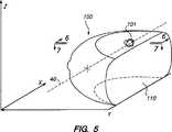
図5は、圧迫された胸部組織の斜視図であり、本発明による生検システムにおいて用いられる基準軸を示している。
図6は、図5の圧迫された胸部組織の、図5の6−6線におけるY−Z表示例を示す。
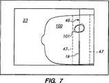
図7は、図5の圧迫された胸部組織の、図5の7−7線におけるX−Y表示例を示し、生検針が組織内に部分的に挿入された状態を示す。
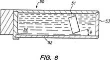
図8は、患者の胸部線の近傍または胸部線内に延びる生物学的特徴部のイメージングを可能にする、本発明に基づき構成された超音波スキャニングシステムの断面図である。
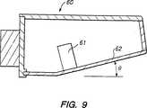
図9は、図8のシステムの別の実施態様を示す断面図である。
発明の詳細な説明
本発明は、例えば断層撮影または乳房X線撮影などによって示される、生物学的組織の生検を行うためのシステムに関するものである。概観としては、本発明の装置は、予め格納された、あるいはリアルタイムの超音波イメージ上を用いて生検針の初期位置を決定することにより、針の軌跡が、例えば病変と疑わしい部分などのターゲット組織領域に交わる確信が、高くなる。
本明細書で説明する第1の実施態様例において、生検システムはスタンドアローンの断層撮影装置を包含する。別の実施態様において、生検システムは、本願において援用する共通に譲渡された米国特許第5,479,927号に記載されるような断層乳房X線撮影システムと共に用いられ得る。
図1を参照して、本発明の原理に基づいて構成された生検システム10を説明する。システム10は、生検台11およびコンピュータディスプレイシステム12を有している。生検台11は、基部17と頂部ブロック18との間の支持部材16上に可動に設けられた、超音波スキャナ13、組織支持台14、および針支持システム15を有している。生検針19は、詳細に後述するように、針支持システム15によって解除可能に保持されている。針支持システム15は、ケーブル21を介してコンピュータディスプレイシステム12のコンピュータ20に取外し可能に結合されており、生検針の動きがコンピュータディスプレイシステム12のモニタ23上に表示される。
超音波スキャナ13は、上記援用の米国特許第5,479,927号の図7を参照して記載されているように、図1に示す座標軸によって示されるX−Y平面内において移動できるように設けられた、環状あるいは直線状配列の超音波トランスデューサを有するように構成されてもよい。特に、超音波トランスデューサは、ベルト、ケーブル、駆動ねじ、または同様のメカニズムからなるシステムによって駆動されるキャリッジ上に設けることにより、生検すべき組織の3次元データモデルを生成するのに十分な一連の平面に沿ってスキャニングを提供することにしてもよい。
超音波スキャナ13は、組織を組織支持台14に対して固定するための上部圧迫板として機能する、下面を有している。超音波スキャナ13の圧迫板は、ポリイミド、ナトリウム系アイオノマー樹脂またはポリメチルペンテンなど、上述の特許に記載の材料のうち任意のもので構成し得るが、本発明のスタンドアローンの断層撮影アプリケーション例においては、圧迫板の放射線透過性は必要でないことが当然理解されるであろう。超音波スキャナ13はまた、詳しく後述するように、患者の胸部線の近傍または胸部線内の生物学的特徴部のイメージングを可能にするためのある種の改良が施されていてもよい。超音波スキャナによって生成されたイメージングデータは、ケーブル22を介して、コンピュータディスプレイシステム12に供給される。
図1の実施態様における組織支持台14は、例えば金属、ファイバーグラスまたは、例えばUHMWプラスチック(超高分子量ポリエチレンなど)等のプラスチックなど、またはその組み合わせによる、丈夫な材料から構成されており、圧迫状態における生物学的組織の下面を支持する機能を有する。特に、組織支持台14および超音波スキャナ13は、組織に対して十分な圧迫を提供し、かつ患者の大きさを受け入れるように高さ調節を提供するために、支持部材16に対して取り外し可能かつ調節可能に設けられてもよい。
図示のコンピュータディスプレイシステム12は、移動可能なカート24上に設けられたモニタ23およびコンピュータ20を有している。コンピュータ20は、例えば、80386以上のマイクロプロセッサあるいは同様なプロセッサ、超音波スキャナ13によって生成されたイメージングデータおよび針支持システム15によって生成された位置決めデータを操作するためのソフトウェアプログラムを格納するのに十分な、ハードディスクドライブまたは同様なメモリ装置を有する、汎用のパーソナルコンピュータであり得る。システム12は、超音波トランスデューサ13および針支持システム15から受け取ったデータを処理するための、1つ以上の追加的なカードを有しているが、その構成の詳細は通常の超音波取得原理のアプリケーションを用いたものであり、本発明の一部を構成するものではないことが、当然理解されるであろう。
図2を参照して、針支持システム15の実施態様例を説明する。針支持システム15は、アンカーバー25、支持ブロックアセンブリ26および27、Y軸トラック28、Y軸リニアエンコーダ29、支持板アセンブリ30、Z軸トラック31、Z軸リニアエンコーダ32、および針支持ブロックアセンブリ33を有している。
アンカーブロック25は、組織支持台14の側面に設けられた溝34に対して近い許容度ではまり込むような寸法を有する。組織支持台14の溝部には位置決め穴35が設けられており、ロック用ペグ(図示せず)が穴35およびアンカーブロック25の穴36の中を通って延びることができることにより、アンカーブロック25が(従って針支持システム15も)、組織支持台14に対して公知の関係になるようにしっかりとロックされる。
溝34およびアンカーブロック25の組み合わせにより、針支持システム全体に高い剛性が提供される一方、組織支持台14の各側面に設けられた溝34により、臨床医が左側からでも右側からでも組織に近づくことを可能にする。また、超音波スキャナ13および組織支持台14は、例えば、それ自体支持部材16に旋回可能に接続されたブロックに対して調節可能に設けることにより、生検システム全体が生物学的組織に対して回転可能であるようにし、接近できる組織領域を増やすことができる。
支持ブロックアセンブリ26および27は、Y軸トラック28をアンカーブロック25に、従って組織支持台14に対して堅く固定する。Y軸リニアエンコーダ29は、例えば、インクリメンタルバイナリカウンタを有しており、Y軸トラック28の長さ方向に沿って摺動可能である。好適な実施態様においては、Y軸トラックはその中に、平行に離れて設けられた銅箔からなるプリント基板構成を有しており、Y軸リニアエンコーダ29が、エンコーダが手動でY軸トラック28に沿って摺動される際の静電容量を感知するヘッドと、隣接する銅箔間で補間を行うための回路とを有していてもよい。Y軸リニアエンコーダ29がY軸トラック28に沿って摺動される際、予め定められた基準ポイント(好ましくは患者の胸壁から最も遠い位置に位置するハードストップ)からの変位に対応した信号を出力する。リニアエンコーダ29から出力される信号は、ジャック21aを介してエンコーダ29に接続されるケーブル21を介して、コンピュータ20に供給される。
支持板アセンブリ30は、Z軸リニアエンコーダ32を、Y軸リニアエンコーダ29に対して堅く固定する。Z軸リニアエンコーダ31はリニアエンコーダ32内に摺動可能に係合していることにより、リニアエンコーダ32は、トラック32が上昇または下降される際の、Z軸トラックのリニアエンコーダ32に対する変位に対応する信号を生成する。リニアエンコーダ32から出力される信号は、ジャック21bを介してエンコーダ32に接続されるケーブル21を介して、コンピュータ20に供給される。リニアエンコーダ32は、例えば、組織支持台14の上面または超音波スキャナ13の下面を、その基準ポイントとして用い得る。リニアエンコーダ29および32は、好ましくは、約プラスマイナス0.05mmの変位精度を有しており、エンコーダ29および32上のスイッチ、またはソフトウェア制御によりリセット可能である。
リニアエンコーダ29は、エンコーダをY軸トラック28上のある位置にロックするための手段(図示せず)を有しており、リニアエンコーダ32は、Z軸トラック31をエンコーダ32中のある位置にロックするための手段(図示せず)を有している。リニアエンコーダ29および32、ならびに組み合わせトラック28および31は、スイス国CrissierのSylvac S.A.から入手可能であり、米国において、イリノイ州シカゴのFowler Company, Inc.により、パーツNo.54-050-035(Y軸エンコーダ29)およびNo.54-050-000(Z軸エンコーダ32)として流通されている。
また、当業者には当然理解されるように、リニアエンコーダ29および32は、例えばコンピュータマウスおよびTVゲームのジョイスティックなどの適切に設計されたロータリーエンコーダ、またはリニア可変変位トランスデューサもしくはリニア電位差計などの他の適切な変位感知要素から構成されていてもよい。
針支持アセンブリ33は、生検針ホルダを有している。生検針ホルダは、初期位置決めおよび挿入の際には生検針を安定に保持するが、解除可能に生検針を解放(release)することにより、生検針が患者組織内に挿入された後のフリーハンド移動を可能にする。
図2の実施態様例において、針支持アセンブリは上部ブロック33aおよび下部ブロック33bを有する。針支持部材は、例えば下部ブロック33bの下面に設けられたスロット(図示せず)により、Z軸トラック31の上端に取り外し可能に結合される。上部ブロック33aは、その下面に半円形の管溝33cを有しており、下部ブロック33bは、その上面に半円形の管溝33cを有している。上部ブロック33aおよび下部ブロック33bの管溝33cは、この2つの部品が互いに位置合わせされた際に組合わさって孔(bore)を形成し、生検針19がこの孔を通して摺動可能に位置される。
また、上部ブロック33aおよび下部ブロック33bは好ましくは、例えば図2の実施態様例におけるブロック状凸部33eおよび対応する凹部33fのような、組み合わせ凸部および凹部を有している。孔33gは、この2つのブロックが互いに組み合わせられた際に、上部ブロック33aおよび下部ブロック33bにわたって位置合わせされることにより、ピン33dが孔33g中に摺動可能に位置させることができる。このようにして、上部ブロック33aおよび下部ブロック33bは、ピン33dによって互いに堅く固定されることにより、生検針19の初期位置決めおよび挿入の間、生検針19を担持する。管溝33cによって形成された孔に挿入されるとき、生検針は孔と並んだ軌跡を有する。
患者に針が挿入されると、ピン33dを孔33gから取り除くことにより、臨床医の邪魔にならないように上部ブロック33aを取り除き下部ブロック33bを動かすことができる。この構成により、臨床医がこのように生検針を針支持アセンブリ33から取り除き、針先端の動きをディスプレイ23で観察しながら生検針を手動で操作することが可能になる。従って、針支持アセンブリ33は、定位生検システムの精度で生検針の初期位置決めすることを可能にする一方、フリーハンド超音波技術のフレキシビリティーおよび操作性を提供する。
図3A〜3Bに、針支持アセンブリ33’の別の実施態様例を示す。図3Aに示すように、針支持アセンブリ33’は、要素37aおよび37bに形成されたV字型管溝を有するブロック37と、一体的に成形されたロック用アーム38とを有している。ロック用アーム38は、閉位置において生検針19に対して係合するように設けられたリッジ38aを有している。ロック用アームはまた、ギザ部38cを含むラッチ部分38を有しており、ギザ部38cはブロック37上のギザ部37cと係合する。
ロック用アーム38は、要素37aと37bとの間に近い許容度ではまり込むような寸法を有することによって、リッジ38aが広い範囲の寸法を有する生検針に対して係合することを可能にする、図3Bおよび3Cに示すように、針支持ブロック33’は、この支持体をZ軸トラック31に結合するためのスロット37dを有していてもよい。ロック用アーム38は、生検針19を患者の組織に対してイメージガイドされた位置合わせするために、生検針19を要素37aおよび37bに形成されたV字型管溝中に安定に係合するが、ロック用アーム38をブロック37から上方に離すことにより、生検針をすぐに針支持アセンブリ33’から解放することが可能である。
針支持アセンブリ33および33’は好ましくは、滅菌が可能な丈夫かつ軽量な材料から形成されている。例えば、針支持アセンブリ33および33’は、繰り返し滅菌することが可能な機械加工されたアルミニウムから形成されていてもよく、あるいは、1回使用するごとに捨てられる射出成形されたプラスチック要素から形成されていてもよい。針支持アセンブリ33’は、好ましくはポリエチレンなどの適切なプラスチックから一体成形される。
図4を参照して、図1〜3の生検システムの別の実施態様を説明する。図4において、図1〜3のシステムと同様な要素を、例えば生検針支持システム115のように、100番台の参照符号で示している。
組織支持台114が複数の開口部114’を有する格子状構造を有しており、針支持システム115が組織支持台114の下部に設けられている点で、図4の生検システムは図1〜3のものとは異なっている。図4から明らかなように、図4のシステムの構成は、胸部の下面から組織の生検を行うことにより、針を突き刺すことに起因する瘢痕を目立たなくすることを可能にする。また、複数の開口部114’が、患者の組織(図4において点で示している)を支持するために用いられる組織支持台114の全領域にわたって拡がっていくことがわかる。
図4の好適な実施態様においては、組織支持台114は、約0.5インチ(12.7mm)の厚さを有しており、適切な剛性プラスチック、金属合金、またはその組み合わせにより形成される。組織支持台114は、約1.5インチ(38mm)の複数の正方形状開口部を、最小限の再位置決めで患者の組織の下側の大部分に接近することを可能にするのに十分なスペーシングで、ある1面に有している。
図1および図2に示す矢印方向を参照すれば、図4の針支持システム115は、X−Y平面にあることになり、Y軸トラック128、Y軸リニアエンコーダ129、X軸トラック131、X軸リニアエンコーダ132、および針支持アセンブリ133を有している。X軸トラック131は、支持ブロックアセンブリ126によって組織支持台114上に設けられており、Y軸リニアエンコーダ132がその上に摺動可能に係合している。Y軸トラック128は、Y軸リニアエンコーダ129内に摺動可能に係合しており、Y軸リニアエンコーダ129自体は、図2を用いて説明したようにX軸リニアエンコーダに結合されている。Y軸トラック128は、生検針119に対して係合する針支持アセンブリ133を担持している。
針支持システム115は、ケーブル121を介してコンピュータディスプレイシステム12に接続されている。上述のように図4のシステムの部品の物理的な構成が異なること以外は、図1〜3のシステムについての説明が図4のシステムについて適用される。
図5〜7を参照して、図1〜4のシステムの動作を説明する。図5を参照して、生物学的組織の塊100、具体的にはヒトの胸部を、組織支持台14の上面と超音波スキャナ13の下面との間で圧迫された状態(明瞭さのため、超音波スキャナ13および組織支持台14は図5には示していない)で示している。組織100は患者につながったままであることが当然理解されるであろう。組織100は、病変と疑わしい部分に相当する領域101を含んでいる。
図5は、以下の説明で用いる基準軸を示している。特に、Y軸は患者の胸壁から垂直に延びる方向であり(平面110)、Z軸方向は立面方向であり、X軸方向は患者の胸壁に沿って平行に延びている。投影された針の軌跡40は、組織100の皮膚に場所41で接触し、病変と疑わしい領域101に交わる。
動作中において、患者の組織塊は、超音波スキャナ13の下面と組織支持台14の上面との間で圧迫され図5に示す組織塊100の形状を呈する。組織塊にわたって圧迫負荷を分布させ、患者の不快感を和らげ、超音波スキャナの組織塊に対する結合を改善するために、ゲルパッド(gel pad)を用いてもよい。
次に、臨床医は、超音波スキャナ13を操作してY−ZまたはX−Z平面方向に1連の2次元スライスを生成することにより、組織の徹底的な超音波検査を行い得る。これらのスライスは次に、デジタル操作されることにより、組織塊の内部特徴部のホログラフイメージをディスプレイ23上に提供するか、組織を通る任意の平面のビューを提供することができる。
生検が示されたとき、臨床医は、新しい針支持アセンブリ33または33’をZ軸トラック31に結合し、生検針を針支持アセンブリに係合させる。次に、臨床医はディスプレイ23上で観察するための組織100を通るビュー平面、例えば図6のような立面ビュー(すなわちY−Z平面を通る)などを、選択する。生検針が臨床医によって手動で組織100近くをY−Z平面内で動かされるにつれ、針支持システム15のエンコーダ29および32は信号を出力し、信号はコンピュータ20によって処理され、選択されたビュー平面の超音波イメージ上に、例えば十字線45として表示される。針支持アセンブリの寸法は、生検針の位置とエンコーダ29および32との間の視差が適切に考慮されるように、よく調節されていることが当然理解されるであろう。
生検針19を組織100近くに手動で移動することにより、針支持システム15は、コンピュータ20に対応する座標を供給し、これにより、臨床医は十字線45を病変と疑わしい領域101に合わせることができる(図6では十字線45から点数の十字線45’へと移動する、点線の矢印で示している)。
十字線45が領域101と合わせられたならば、臨床医は、生検針の軌跡を評価するために、組織100を通るさらなるビューを選択し得る。例えば、臨床医は、生検針19の軌跡を表示するために、図7に示すように組織100を通る平面ビュー(すなわちX−Z平面を通る)を選択し得る。図7のような平面図において、生検針は、超音波イメージ上に、好ましくは十字線ではなく線46として投影される。
生検システム10はさらに、超音波スキャナ13を組織内部のイメージを連続的に生成するように操作することによって、組織塊100全体あるいはその選択された部分の超音波イメージを連続的に更新することができる。このようにして、例えば、臨床医が生検針を領域101に合わせたとき、針支持システム15をY−Z平面内でそれ以上動かないようにロックし、組織100のうち生検針軌跡近傍の部分、例えば図7に示す点線47内部のみをスキャンするように適切なコマンドを超音波スキャナに送り得る。
臨床医は次に、針を針支持アセンブリを通って患者の組織内に入るようにX方向に摺動させることによって、生検針19を組織100中へと延ばす。図7に示すように超音波イメージの平面ビューが表示されている場合は、臨床医は生検針が組織塊を貫通していく進行状態をモニターし得る。
生検針19の軌跡の線46に沿って領域101のサンプルを得た後、臨床医は、ピン33dを取り去ることにより生検針19を針支持アセンブリ33から解除するか、針支持アセンブリ33’のロック用アーム38を取り去る。次に、臨床医は生検針を操作することによって、組織100の皮膚に突き刺し傷を増やすことなく、超音波イメージガイド下において領域101の追加的なサンプルを収集し得る。
図4のシステムの動作は、針支持システム115が、患者の胸部下に位置するX−Y平面で操作される点以外、上記と同様である。臨床医が組織100の内部組織の完全な超音波イメージを得ると、X−Y平面内のビューが選択される。このビューは図6のものと同様な様子を呈する。針支持システム115を操作するにつれ、図6に示すように、対応する十字線45が表示された超音波ビュー平面上で動き回る。
生検針を次に、組織支持台114内の最も近い開口部114’を通して挿入することにより、生検を行い得る。図1〜3のシステムと同様に、生検針が組織100に挿入される際の進行状態を、後に超音波スキャナ13を用いてイメージングすることによって得ることができる。特に、図4のシステムを用いてY−Z平面で生成されたイメージは、図7に示すものと同様な様子を呈する。
上述のように、本発明の生検システム10は従来公知のシステムおよび技術に対して多大な利点を提供する。フリーハンド超音波技術と異なり、本発明は、生検針の正確な初期位置合わせを提供するため、臨床医は生検針の提案された軌跡が興味のある領域に交わることを高く確信でき、針の抜き差しの回数および、複数の針経路に沿って悪性細胞を播種してしまうリスクを減少することができる。
また、超音波スキャン内に入ってくる針の部分のみを表示するフリーハンド技術と異なり、本発明は、針トラックの全長にわたって生検針を連続的にモニタリングすることを提供する。例えば、フリーハンド超音波技術は、生検針軌跡が皮膚を既に突き刺してからでないと生検針軌跡に関する情報を提供しない。対して、本発明は、挿入前から、針軌跡の予測を可能にする。
同様に、本発明の生検システム10は、定位X線システムに比較して多大な効果を有する。例えば、本発明の生検システムは、X線の使用にともなう危険なイオン化照射の使用を無くし、針の位置付けのため座標計算の必要を無くし、フォローアップとしてのイメージングの必要無しに、実際の針軌跡のリアルタイムでのモニタリングを提供し、1回の突き刺し傷を通してターゲット領域内の複数の領域を臨床医がサンプルすることを可能にする。また、本発明のシステムは、定位X線システムほど複雑でなく、比例して構築、使用、維持費用が安い。
さらに、本発明の生検システムは、他の超音波スキャニング装置、例えば上記米国特許第5,479,927号に記載の断層乳房X線撮影装置と共に用い得ることが、理解されるであろう。例えば、本発明の生検システム15を上記特許に記載された超音波スキャナを含むX線システムにおいて使用するためには、針支持システム15をダミーX線フィルムカセットに対してつなぎ止め得る(anchor)。ダミーX線フィルムカセットは、超音波スキャナと上述の生検針支持システムを組み合わせて使用することを可能にするために、X線システムのフィルムホルダ/回折格子アセンブリ(しばしば「Bucky」と呼ばれる)中に設置される。
図8および9を参照して、本発明の生検システムに適切に用い得るさらなる特徴を説明する。図8を参照して、上記および米国特許第5,479,927号に記載の超音波スキャナ13と実質的に同様の設計を有する超音波スキャナ50の断面を示す。超音波スキャナ50は、トランスデューサ51が圧迫板52に直接結合されていず、角度θだけ圧迫板から離れて傾けられている点において、上記実施態様とは異なっている。さらに、圧迫板52と前部パネル53との両方を、剛性の超音波透過性(sonolucent)材料で構成している。
超音波スキャナ50内において、水54またはその他の適切な音伝導性媒体で満たすことにより、トランスデューサ51と圧迫板52との適切な音響的結合を得ることができる。この構成は、スキャナの直下に位置する組織のイメージングを提供するだけでなく、患者の胸壁の近傍あるいは胸壁内部に位置する組織のイメージングも提供することが予期される。
図9は、向上したイメージングを提供するように設計された超音波スキャナの別の実施態様を示している。特に、超音波トランスデューサ61および圧迫板62が水平方向に対して角度θ’で傾いている点を除き、図9の超音波スキャナ60は上述の超音波スキャナ13と同様の設計である。超音波トランスデューサ61および圧迫板62の両方とも角度を付けているため、トランスデューサ61は、上記米国特許第5,479,927号に記載の結合手段を用いて圧迫板62に音響的に結合され得る。圧迫板62の傾き角はまた、患者の胸部線の近傍または胸部線内に延びる内部特徴部の超音波イメージングを可能にすることが、予期される。
本発明の好適な実施態様例を上記に説明したが、発明から逸脱することなく様々な変更および改変をなし得、また付属の請求項は発明の真の趣旨および範囲内にあるそのような変更および改変を全て包含することを意図されていることが、当業者には明らかであろう。Field of Invention
The present invention relates to an apparatus and method for performing a biopsy of a biological tissue, and more particularly to performing a biopsy of a biological tissue while being guided by ultrasound imaging.
Background of the Invention
Devices and methods are known for identifying tumor masses suspected of being malignant, for example, by using radiographic and sonographic techniques. Typically, a subsequent biopsy is performed on such a tissue mass to determine the malignant state or extent to determine further courses of treatment. For example, by biopsying an area suspected of containing a mammogram, it is determined whether the lesion is malignant or benign. Determine, for example, mastectomy, radiation therapy or chemotherapy.
Conventional biopsy methods are based on minimally invasive techniques such as fine needle aspiration using a 21 gauge hypodermic needle and a large core biopsy using a 14 gauge needle mounted on an automated biopsy gun. Open procedure for surgical excision. Minimally invasive techniques are gaining wide acceptance because they are faster and cheaper than surgical resection, and are safe and less damaging to the patient.
However, a common problem with previously known minimally invasive biopsy techniques is that the biopsy needle can really obtain a tissue sample from a suspicious portion of the lesion rather than the healthy tissue surrounding the lesion. Conventionally known techniques to ensure that the biopsy needle trajectory enters the suspicious area are, for example, Fornage et al., “Ultrasound-Guided Needle Biopsy of The Breast And Other Interventional Procedures”, Radiologica Clinics of North America, Vol. 30, No. 1 (January 1992), Fornage et al., “Breast Masses: US-Guided Fine Needle Aspiration Biopsy” Radiology, 162: 409-414 (February 1987), Parker et al., “US -Guided Automated Large-Core Breast Biopsy ”, Radiology, 187: 507-511 (May 1993) and Parker and Jobe,“ Large-Core Breast Biopsy Offers Reliable Diagnosis ”, reprint from Diagnostic Imaging (October 1990) ).
The above document describes free-hand ultrasound technology, inserting a biopsy needle into a suspected lesion, holding a linear array of ultrasonic transducers in one hand, and placing the needle into the tissue with the other hand It is done by inserting. In particular, holding the ultrasound transducer above the midline of the suspicious mass and then inserting the needle (or automated biopsy gun needle) into the tissue near the base of the transducer so that the tip of the needle is being ultrasonically scanned To appear in. Further, when using a biopsy gun, additional manpower may be required to stabilize the biopsy gun during use and to hold the ultrasonic transducer.
As described in Fornage et al. And Paker et al., Freehand technology is difficult when a suspicious part is located near the patient's chest wall or prothesis. These references also emphasize that the results obtained can be dramatically influenced by the skill level of the practitioner when using freehand technology. All of the above documents dismiss the use of biopsy needle guides that can be connected to an ultrasonic transducer. This is because the guide interferes with the flexibility and operability necessary to obtain good results.
The Parker and Jobe literature also describes a stereotactic mammography biopsy system. In such a system, it is possible to calculate the coordinates of the lesion by taking two X-ray images of breast tissue from different angles. A biopsy needle--an automated biopsy gun (e.g., Biopyt available from CR Bard. Inc., Bard Division, Covington, GA) typically mounted in a rigid housing attached to a biopsy table Move to the calculated coordinates and actuate. Further, by taking two chest tissue X-rays, it is confirmed whether or not the needle has actually sampled an area suspected of being a lesion.
Parker and Jobe documents describe the shortcomings of add-on localization systems. That is, there is a possibility that the previously performed stereo calculation is wasted due to the movement of the chest. This document also states that the Mammotest system sold by Fischer Imagin Corporation of Thornton, Colorado, overcomes some of the disadvantages of add-on localization systems, but creates significant cost differences. Yes.
However, a drawback common to all stereotaxic systems is that the tissue is exposed to ionizing radiation that can be harmful to health due to the need to take multiple x-rays of the tissue. These systems also cannot provide real-time imaging of the needle trajectory, and as described in Parker and Jobe literature, the computed coordinates are wasted by moving the chest tissue along the way. This can lead to misleading biopsy samples. In fact, the clinician does not realize that the biopsy needle has deviated from the intended target until a stereotaxic image is taken as a follow-up.
Further, since the biopsy needle is fixed in the fixed housing for the purpose of fixing the locus of the biopsy needle, the stereotaxic system has no freedom of movement of the biopsy needle with respect to the target tissue. As a result, it may be necessary to insert and remove the needle several times to fully characterize the tissue.
A major drawback of the previously known methods and devices described above is due to the inability of the clinician to evaluate in real time the correct trajectory from the breast surface of the biopsy needle to the area suspected of being a tumor or lesion. To increase the level of confidence that suspicious lesions have been recovered, even when guided by freehand ultrasound scanning, clinicians typically remove and insert biopsy needles 10-15 times or more. Must. And each of the needle aspiration samples must be tested separately, which greatly increases the total cost of the procedure.
Similarly, in a stereotaxic system, it is necessary to insert the needle multiple times in order to fully characterize a suspicious area due to the inability to monitor tissue movement and the inability to manipulate a biopsy needle once inserted. Will occur. And again, each of these multiple samples must be tested individually to correctly characterize the suspected lesion.
Repeating the insertion and removal of the biopsy needle in this manner can cause great discomfort for the patient. Also, even if biopsy shows that no surgical treatment is needed, repeated insertion of the biopsy needle may leave a scar that is not cosmetically beautiful in the patient.
A further disadvantage of these previously known methods and devices is that the needle track may be inoculated with potentially malignant tumor cells. For example, in a previously known method, the clinician had to insert a needle several times to see if he had sampled cells from the target tissue, so the clinician did not think he had entered the area suspected of being a tumor There is a possibility that malignant cells will be seeded along the path of the needle that was actually contained.
In view of the above, by enabling the insertion positioning of the biopsy needle to have a predetermined trajectory in real time to the targeted tissue region, reducing the need to repeatedly insert and remove the needle to obtain a biopsy sample, It would be desirable to provide an apparatus and method.
The possibility of malignancy by seeding along multiple needle paths by enabling real-time biopsy needle insertion positioning so that the needle trajectory enters the targeted tissue region with high confidence It would be desirable to provide devices and methods that reduce the risk of tumor cells having a spread.
In addition, the biopsy needle can be inserted and positioned within the tissue region along a predetermined trajectory, allowing the clinician to change the trajectory once the needle has been inserted, thereby repeatedly piercing the skin It would be desirable to provide an apparatus and method that reduces the number of scars caused by it.
A further disadvantage of previously known biopsy systems, including those using ultrasound imaging of biological tissue, is the inability to evaluate tissue features near or extending to the chest wall. Such features could typically not be reached by conventionally known X-ray and tomographic imaging techniques. This is because X-ray radiation cannot be directed to the X-ray film, and in the case of a tomography system, a complicated structure including submerging the tissue in the elutriation is required.
Accordingly, it is desirable to provide a biopsy system with improved imaging capabilities to provide images of biological features that extend near or within the chest line of the patient.
Summary of invention
In view of the above, an object of the present invention is to provide an apparatus and method that enables initial positioning of biopsy needle insertion in real time so as to have a predetermined trajectory to the targeted tissue region. As a result, the need to repeatedly remove and insert the needle to obtain a biopsy sample is reduced, improving the efficiency of the medical procedure and reducing patient pain during the medical procedure.
Another object of the present invention is seeded along multiple needle paths by enabling real-time biopsy needle insertion positioning so that the needle trajectory enters the targeted tissue region with high confidence. It is an object of the present invention to provide an apparatus and method that reduces the risk of spreading potentially malignant tumor cells.
Yet another object of the present invention is to enable the biopsy needle to be positioned within the tissue region along a predetermined trajectory and to allow the clinician to change the trajectory once the needle has been inserted. By providing a device and method that reduces the number of scars resulting from repeated piercing of the skin.
Yet another object of the present invention is to more thoroughly examine tissue by allowing a clinician to image biological features within tissue extending near or into the chest wall of the patient, To provide an apparatus and method that allows a more thorough biopsy to be performed if there are signs.
The above and other objects of the present invention provide an apparatus and method for guiding a biopsy needle to an initial insertion position by correlating the actual needle position before insertion and the trajectory expected after insertion in real time. This is achieved by the principle of the present invention. In the preferred embodiment, the needle position is tracked electronically and projected onto a pre-stored or real-time tissue image. The clinician can thus observe the features of the imaged tissue where the biopsy needle is likely to meet during insertion. In addition, ultrasonic scanning of selected trajectories may be provided to evaluate the penetration depth upon insertion of the biopsy needle.
The ultrasound scanning provided by the apparatus of the present invention provides imaging of biological features that extend near or within the patient's chest line by angling the ultrasound transducer or upper compression plate relative to the chest wall. May have the ability to provide.
Further features of the invention, its nature and various advantages will be more apparent from the accompanying drawings and the following detailed description of the preferred embodiments.
[Brief description of the drawings]
FIG. 1 is a perspective view of an exemplary embodiment of a biopsy system according to the present invention.
2 is an exploded perspective enlarged view of the portion of the biopsy system of FIG. 1 shown in the inset FIG. 2 of FIG.
3A-3C are perspective and elevation views, respectively, of an open position and a closed position of another needle support assembly.
FIG. 4 is a perspective view of another configuration of the biopsy system of FIGS. 1 and 2 viewed from below.
FIG. 5 is a perspective view of a compressed breast tissue showing a reference axis used in a biopsy system according to the present invention.
FIG. 6 shows a YZ display example of the compressed breast tissue of FIG. 5 along line 6-6 of FIG.
FIG. 7 shows an XY display example of the compressed breast tissue of FIG. 5 taken along line 7-7 of FIG. 5, and shows a state where the biopsy needle is partially inserted into the tissue.
FIG. 8 is a cross-sectional view of an ultrasound scanning system constructed in accordance with the present invention that enables imaging of biological features that extend near or within a patient's chest line.
FIG. 9 is a cross-sectional view illustrating another embodiment of the system of FIG.
Detailed Description of the Invention
The present invention relates to a system for performing a biopsy of a biological tissue, as shown, for example, by tomography or mammography. As an overview, the device of the present invention determines the initial position of a biopsy needle using pre-stored or real-time ultrasound images so that the needle trajectory is a target tissue such as a portion suspected of being a lesion. Confidence in territory increases.
In the first example embodiment described herein, the biopsy system includes a stand-alone tomography apparatus. In another embodiment, the biopsy system can be used with a tomographic x-ray system as described in commonly assigned US Pat. No. 5,479,927, incorporated herein by reference.
With reference to FIG. 1, a biopsy system 10 constructed in accordance with the principles of the present invention will be described. The system 10 includes a biopsy table 11 and a
As described with reference to FIG. 7 of the above-incorporated US Pat. No. 5,479,927, the ultrasonic scanner 13 is provided so as to be movable in the XY plane indicated by the coordinate axes shown in FIG. It may be configured to have an annular or linear array of ultrasonic transducers. In particular, the ultrasonic transducer is provided on a carriage driven by a system consisting of a belt, cable, drive screw, or similar mechanism, thereby providing a series sufficient to generate a three-dimensional data model of the tissue to be biopsied. Scanning may be provided along the plane.
The ultrasonic scanner 13 has a lower surface that functions as an upper compression plate for fixing the tissue to the
The
The illustrated
An example embodiment of the
The
The combination of the
The support plate assembly 30 firmly fixes the Z-axis
The
Also, as will be appreciated by those skilled in the art,
The
In the example embodiment of FIG. 2, the needle support assembly has an
Further, the
When the needle is inserted into the patient, the
3A-3B illustrate another example embodiment of a needle support assembly 33 '. As shown in FIG. 3A, the needle support assembly 33 'includes a
The locking
With reference to FIG. 4, another embodiment of the biopsy system of FIGS. In FIG. 4, the same elements as those in the system of FIGS.
The biopsy system of FIG. 4 is similar to the biopsy system of FIG. Different from ~ 3. As can be seen from FIG. 4, the configuration of the system of FIG. 4 allows a biopsy of the tissue from the underside of the chest to obscure scars resulting from needle sticks. It can also be seen that the plurality of
In the preferred embodiment of FIG. 4, the
Referring to the arrow directions shown in FIGS. 1 and 2, the
The
The operation of the system of FIGS. 1 to 4 will be described with reference to FIGS. Referring to FIG. 5, a
FIG. 5 shows a reference axis used in the following description. In particular, the Y-axis is the direction that extends perpendicularly from the patient's chest wall (plane 110), the Z-axis direction is the elevation direction, and the X-axis direction extends in parallel along the patient's chest wall. The projected
In operation, the patient's tissue mass is compressed between the lower surface of the ultrasound scanner 13 and the upper surface of the
The clinician can then perform a thorough ultrasound examination of the tissue by manipulating the ultrasound scanner 13 to generate a series of two-dimensional slices in the YZ or XZ plane direction. These slices can then be digitally manipulated to provide a holographic image of the internal features of the tissue mass on the
When a biopsy is indicated, the clinician couples a new
By manually moving the
If the
The biopsy system 10 further continuously updates the ultrasound image of the
The clinician then extends
After obtaining a sample of
The operation of the system of FIG. 4 is similar to the above except that the
A biopsy can then be performed by inserting a biopsy needle through the
As mentioned above, the biopsy system 10 of the present invention provides significant advantages over previously known systems and techniques. Unlike freehand ultrasound technology, the present invention provides accurate initial alignment of the biopsy needle so that the clinician is highly confident that the proposed trajectory of the biopsy needle intersects the area of interest, The number of insertions and removals and the risk of seeding malignant cells along multiple needle paths can be reduced.
Also, unlike the freehand technique that displays only the portion of the needle that enters the ultrasound scan, the present invention provides for continuous monitoring of the biopsy needle over the entire length of the needle track. For example, freehand ultrasound technology does not provide information about the biopsy needle trajectory until the biopsy needle trajectory has already pierced the skin. On the other hand, the present invention makes it possible to predict the needle trajectory before insertion.
Similarly, the biopsy system 10 of the present invention has a significant effect compared to a stereotactic X-ray system. For example, the biopsy system of the present invention eliminates the use of dangerous ionizing radiation associated with the use of X-rays, eliminates the need for coordinate calculations for needle positioning, and eliminates the need for imaging as a follow-up. Provides real-time monitoring of the trajectory and allows the clinician to sample multiple areas within the target area through a single puncture wound. Also, the system of the present invention is not as complex as a stereotactic X-ray system and is proportionally cheaper to construct, use, and maintain.
It will further be appreciated that the biopsy system of the present invention may be used with other ultrasound scanning devices, such as the tomographic x-ray apparatus described in US Pat. No. 5,479,927, supra. For example, in order to use the
With reference to FIGS. 8 and 9, additional features that may be suitably used in the biopsy system of the present invention will be described. Referring to FIG. 8, a cross section of an
By filling the
FIG. 9 illustrates another embodiment of an ultrasound scanner designed to provide improved imaging. In particular, the
While preferred embodiments of the invention have been described above, various changes and modifications can be made without departing from the invention, and the appended claims are intended to be within the true spirit and scope of the invention. It will be apparent to those skilled in the art that the invention is intended to encompass all such modifications.
Claims (30)
Translated fromJapanese該組織塊のイメージを提供する超音波スキャナであって、該選択された領域を含む該組織塊のイメージが該ディスプレイ手段上に表示される超音波スキャナと、
該生検器具の先端をある軌跡で保持する保持体と、
該保持体に結合された、該組織塊中への挿入以前に該生検器具の該先端の現在位置に対応する信号を生成する手段であって、該信号は該生検器具の該先端の該選択された領域に対する現在位置を現すシンボルによって該ディスプレイ手段上に表示される、手段と、
を有する装置であって、
該シンボルを該選択された領域に合わせることは、該生検器具の該先端の軌跡が該選択された領域に交わるであろう位置に該支持体を移動することに相当する、
装置。An apparatus for positioning the tip of a biopsy instrument upon insertion into a selected region of a tissue mass for use in a system including a display means,
An ultrasound scanner providing an image of the tissue mass, wherein the image of the tissue mass including the selected region is displayed on the display means;
A holding body for holding the tip of the biopsy instrument in a certain locus;
Coupled to said holding member, a currenthand stagethat generates a signal corresponding to the position of the distal end of the insertion previously biopsy instrument into the tissue mass in, wherein the said signal biopsy instrument Means displayed on the display means by a symbol representing the current position for the selected region of the tip;
A device comprising:
Matching the symbol to the selected area corresponds to moving the support to a position where the trajectory of the tip of the biopsy instrument will intersect the selected area;
apparatus.
生検器具の先端をある軌跡で保持する保持体と、
該保持体に結合された、該組織塊中への挿入以前に該生検器具の該先端の現在位置に対応する信号を生成する手段とを有する装置であって、
該ディスプレイ手段は、組織塊の該選択された領域を含むイメージおよび、該生検器具の該先端の該選択された領域に対する現在位置を現すシンボルを表示することにより、該シンボルを該選択された領域に合わせることは、該生検器具の該先端の軌跡が該選択された領域に交わるであろう位置に該支持体を移動することに相当する、
装置。A device for positioning the tip of a biopsy instrument upon insertion into a selected region of a tissue mass for use in a system including display means and an ultrasound scanner that provides an image of the tissue mass Equipment,
A holding body for holding the tip of the biopsy instrument in a certain locus;
Coupled to said holding member, the apparatus having amanual stepthat generates a signal corresponding to the current position of the tip of the biopsy instrument prior to insertion into the tissue mass in,
The display means displays the selected symbol by displaying an image including the selected region of the tissue mass and a symbol representing a current position relative to the selected region of the tip of the biopsy instrument. Matching the area corresponds to moving the support to a position where the trajectory of the tip of the biopsy instrument will intersect the selected area.
apparatus.
該組織塊を固定する手段と、
該組織塊の該選択された領域を含む超音波イメージを生成する手段と、
該組織塊の該選択された領域を含む該超音波イメージを表示する手段と、
該生検器具の先端をある軌跡で保持する保持体を提供する手段と、
該超音波イメージ以外の、該生検器具の該先端が該組織塊中へ挿入される以前に該生検器具の該先端の現在位置に対応する信号を生成する手段と、
該生検器具の該先端の該選択された領域に対する現在位置を現すシンボルを、該信号に応答して表示する手段と、
該シンボルが該選択された領域に合わさる位置に該支持体を移動することによって、該生検器具の該先端の軌跡が該選択された領域に交わるようにする手段とを備えるシステム。Asystem for positioning the tip of a biopsy instrument to have a predetermined trajectory into a selected region of a tissue mass;
Means for fixing the tissue mass;
Means for generating an ultrasound image including the selected region of the tissue mass;
Means for displaying the ultrasound image including the selected region of the tissue mass;
Means for providing a holder for holding the tip of the biopsy instrument in a certain path;
Means for generating a signal other than the ultrasound image corresponding to the current position of the tip of the biopsy instrument before the tip of the biopsy instrument is inserted into the tissue mass;
Means for displaying, in response to the signal, a symbol representing a current position for the selected region of the tip of the biopsy instrument;
System in which the symbolsandmeans to make by moving the support in a position mating to the selected region intersects a region locus of the tip of the biopsy instrument is the selected.
該組織塊および該生検器具の該先端の該超音波イメージを表示する手段と、
該生検器具の該先端の該組織塊中への挿入を、該表示されたイメージに応答してガイドする手段と、
をさらに備える、請求項26に記載のシステム。Means for inserting the tip of the biopsy instrument into the tissue mass while providing a real-time ultrasound image of the tissue mass and the tip of the biopsy instrument;
Means for displaying the ultrasound image of the tissue mass and the tip of the biopsy instrument;
Means for guiding the insertion of the biopsy instrument into the tissue mass in response to the displayed image;
27. Thesystem of claim 26, further comprising:
該生検器具をフリーハンド操作することによって、該組織塊中における該生検器具の該先端の該軌跡を変更する手段と、
をさらに備える、請求項25に記載のシステム。Means for releasing the biopsy instrument from the support after the tip of the biopsy instrument is inserted into the tissue mass;
Means for changing the trajectory of the tip of the biopsy instrument in the tissue mass by freehanding the biopsy instrument;
Further Rucomprising asystem according to claim 25.
Applications Claiming Priority (3)
| Application Number | Priority Date | Filing Date | Title |
|---|---|---|---|
| US08/421,381US5660185A (en) | 1995-04-13 | 1995-04-13 | Image-guided biopsy apparatus with enhanced imaging and methods |
| US08/421,381 | 1995-04-13 | ||
| PCT/US1996/005123WO1996032066A1 (en) | 1995-04-13 | 1996-04-12 | Image-guided biopsy apparatus with enhanced imaging and methods |
Related Child Applications (1)
| Application Number | Title | Priority Date | Filing Date |
|---|---|---|---|
| JP2005072106ADivisionJP2005237976A (en) | 1995-04-13 | 2005-03-14 | Image-guided biopsy apparatus and method with improved imaging |
Publications (2)
| Publication Number | Publication Date |
|---|---|
| JPH11505446A JPH11505446A (en) | 1999-05-21 |
| JP3705816B2true JP3705816B2 (en) | 2005-10-12 |
Family
ID=23670287
Family Applications (2)
| Application Number | Title | Priority Date | Filing Date |
|---|---|---|---|
| JP53123996AExpired - Fee RelatedJP3705816B2 (en) | 1995-04-13 | 1996-04-12 | Image-guided biopsy device and method with improved imaging |
| JP2005072106AWithdrawnJP2005237976A (en) | 1995-04-13 | 2005-03-14 | Image-guided biopsy apparatus and method with improved imaging |
Family Applications After (1)
| Application Number | Title | Priority Date | Filing Date |
|---|---|---|---|
| JP2005072106AWithdrawnJP2005237976A (en) | 1995-04-13 | 2005-03-14 | Image-guided biopsy apparatus and method with improved imaging |
Country Status (5)
| Country | Link |
|---|---|
| US (1) | US5660185A (en) |
| EP (1) | EP0825833A4 (en) |
| JP (2) | JP3705816B2 (en) |
| AU (1) | AU694865B2 (en) |
| WO (1) | WO1996032066A1 (en) |
Families Citing this family (151)
| Publication number | Priority date | Publication date | Assignee | Title |
|---|---|---|---|---|
| WO1995011627A1 (en) | 1993-10-29 | 1995-05-04 | Neovision Corporation | Methods and apparatus for performing sonomammography and enhanced x-ray imaging |
| US5983123A (en) | 1993-10-29 | 1999-11-09 | United States Surgical Corporation | Methods and apparatus for performing ultrasound and enhanced X-ray imaging |
| JPH10508504A (en) | 1994-09-16 | 1998-08-25 | バイオプシス メディカル インコーポレイテッド | Method and apparatus for identifying and marking tissue |
| US5833627A (en) | 1995-04-13 | 1998-11-10 | United States Surgical Corporation | Image-guided biopsy apparatus and methods of use |
| US6256529B1 (en)* | 1995-07-26 | 2001-07-03 | Burdette Medical Systems, Inc. | Virtual reality 3D visualization for surgical procedures |
| US5820552A (en) | 1996-07-12 | 1998-10-13 | United States Surgical Corporation | Sonography and biopsy apparatus |
| US5851180A (en)* | 1996-07-12 | 1998-12-22 | United States Surgical Corporation | Traction-inducing compression assembly for enhanced tissue imaging |
| US6254538B1 (en)* | 1996-08-15 | 2001-07-03 | Life Imaging Systems, Inc. | System and process for performing percutaneous biopsy within the breast using three-dimensional ultrasonography |
| US5776062A (en)* | 1996-10-15 | 1998-07-07 | Fischer Imaging Corporation | Enhanced breast imaging/biopsy system employing targeted ultrasound |
| KR20000069165A (en) | 1996-11-29 | 2000-11-25 | 라이프 이미징 시스템즈 인코퍼레이티드 | Apparatus for guiding medical instruments during ultrasonographic imaging |
| AU5112698A (en)* | 1996-11-29 | 1998-06-22 | Life Imaging Systems Inc. | Apparatus for guiding medical instruments during ultrasonographic imaging |
| US5810008A (en)* | 1996-12-03 | 1998-09-22 | Isg Technologies Inc. | Apparatus and method for visualizing ultrasonic images |
| US6314310B1 (en)* | 1997-02-14 | 2001-11-06 | Biosense, Inc. | X-ray guided surgical location system with extended mapping volume |
| US6400979B1 (en)* | 1997-02-20 | 2002-06-04 | Johns Hopkins University | Friction transmission with axial loading and a radiolucent surgical needle driver |
| US6270464B1 (en)* | 1998-06-22 | 2001-08-07 | Artemis Medical, Inc. | Biopsy localization method and device |
| US20030135115A1 (en)* | 1997-11-24 | 2003-07-17 | Burdette Everette C. | Method and apparatus for spatial registration and mapping of a biopsy needle during a tissue biopsy |
| EP1079730B1 (en)* | 1997-11-24 | 2007-01-03 | Computerized Medical Systems, Inc. | Real time brachytherapy spatial registration and visualization system |
| USD412748S (en) | 1998-01-22 | 1999-08-10 | Ultraguide, Ltd. | Monitor for medical equipment |
| WO1999051143A1 (en) | 1998-04-07 | 1999-10-14 | Windy Hill Technology, Inc. | Methods and devices for the localization of lesions in solid tissue |
| US6298262B1 (en) | 1998-04-21 | 2001-10-02 | Neutar, Llc | Instrument guidance for stereotactic surgery |
| US6529765B1 (en) | 1998-04-21 | 2003-03-04 | Neutar L.L.C. | Instrumented and actuated guidance fixture for sterotactic surgery |
| US6546277B1 (en)* | 1998-04-21 | 2003-04-08 | Neutar L.L.C. | Instrument guidance system for spinal and other surgery |
| ATE371409T1 (en)* | 1998-05-21 | 2007-09-15 | Christopher J Walshe | SYSTEM FOR FIXING TISSUE |
| US6027457A (en) | 1998-06-18 | 2000-02-22 | United States Surgical Corporation | Apparatus and method for securing tissue during ultrasound examination and biopsy |
| US6056692A (en)* | 1998-07-08 | 2000-05-02 | Schwartz; John Q. | Apparatus and method for locating and marking blood vessels |
| US6351662B1 (en) | 1998-08-12 | 2002-02-26 | Neutar L.L.C. | Movable arm locator for stereotactic surgery |
| US6282437B1 (en) | 1998-08-12 | 2001-08-28 | Neutar, Llc | Body-mounted sensing system for stereotactic surgery |
| US7517348B2 (en)* | 1998-09-03 | 2009-04-14 | Rubicor Medical, Inc. | Devices and methods for performing procedures on a breast |
| JP4443672B2 (en)* | 1998-10-14 | 2010-03-31 | 株式会社東芝 | Ultrasonic diagnostic equipment |
| EP1143845A4 (en)* | 1998-11-25 | 2004-10-06 | Fischer Imaging Corp | User interface system for mammographic imager |
| US6574499B1 (en)* | 1998-11-25 | 2003-06-03 | Xdata Corporation | Mammography method and apparatus |
| US6122542A (en)* | 1998-11-25 | 2000-09-19 | Rubicor Medical, Inc. | Breast stabilization devices and imaging and interventional methods using the same |
| US6535756B1 (en)* | 2000-04-07 | 2003-03-18 | Surgical Navigation Technologies, Inc. | Trajectory storage apparatus and method for surgical navigation system |
| US20030135102A1 (en)* | 2000-05-18 | 2003-07-17 | Burdette Everette C. | Method and system for registration and guidance of intravascular treatment |
| US7494494B2 (en)* | 2000-08-30 | 2009-02-24 | Johns Hopkins University | Controllable motorized device for percutaneous needle placement in soft tissue target and methods and systems related thereto |
| US7615008B2 (en) | 2000-11-24 | 2009-11-10 | U-Systems, Inc. | Processing and displaying breast ultrasound information |
| US7556602B2 (en)* | 2000-11-24 | 2009-07-07 | U-Systems, Inc. | Breast cancer screening with adjunctive ultrasound mammography |
| US7103205B2 (en)* | 2000-11-24 | 2006-09-05 | U-Systems, Inc. | Breast cancer screening with ultrasound image overlays |
| US7597663B2 (en) | 2000-11-24 | 2009-10-06 | U-Systems, Inc. | Adjunctive ultrasound processing and display for breast cancer screening |
| US7940966B2 (en)* | 2000-11-24 | 2011-05-10 | U-Systems, Inc. | Full-field breast image data processing and archiving |
| US6695786B2 (en)* | 2001-03-16 | 2004-02-24 | U-Systems, Inc. | Guide and position monitor for invasive medical instrument |
| FR2823969B1 (en)* | 2001-04-30 | 2003-12-26 | Ge Med Sys Global Tech Co Llc | METHOD FOR TAKING TISSUE DURING X-RAY EXAMINATION AND IMPLEMENTING DEVICE |
| US6733458B1 (en) | 2001-09-25 | 2004-05-11 | Acuson Corporation | Diagnostic medical ultrasound systems and methods using image based freehand needle guidance |
| EP1460938A4 (en) | 2001-11-05 | 2006-07-26 | Computerized Med Syst Inc | Apparatus and method for registration, guidance, and targeting of external beam radiation therapy |
| US20030194050A1 (en)* | 2002-04-15 | 2003-10-16 | General Electric Company | Multi modality X-ray and nuclear medicine mammography imaging system and method |
| US6882700B2 (en)* | 2002-04-15 | 2005-04-19 | General Electric Company | Tomosynthesis X-ray mammogram system and method with automatic drive system |
| US7783089B2 (en)* | 2002-04-15 | 2010-08-24 | General Electric Company | Method and apparatus for providing mammographic image metrics to a clinician |
| US6707878B2 (en) | 2002-04-15 | 2004-03-16 | General Electric Company | Generalized filtered back-projection reconstruction in digital tomosynthesis |
| US6724856B2 (en)* | 2002-04-15 | 2004-04-20 | General Electric Company | Reprojection and backprojection methods and algorithms for implementation thereof |
| US7218766B2 (en)* | 2002-04-15 | 2007-05-15 | General Electric Company | Computer aided detection (CAD) for 3D digital mammography |
| US6748047B2 (en)* | 2002-05-15 | 2004-06-08 | General Electric Company | Scatter correction method for non-stationary X-ray acquisitions |
| US6780179B2 (en) | 2002-05-22 | 2004-08-24 | Rubicor Medical, Inc. | Methods and systems for in situ tissue marking and orientation stabilization |
| EP1531730B1 (en) | 2002-05-31 | 2012-01-18 | U-Systems, Inc. | Apparatus for acquiring ultrasound scans of a breast |
| US7187800B2 (en) | 2002-08-02 | 2007-03-06 | Computerized Medical Systems, Inc. | Method and apparatus for image segmentation using Jensen-Shannon divergence and Jensen-Renyi divergence |
| US7438692B2 (en)* | 2002-10-18 | 2008-10-21 | Mark Tsonton | Localization mechanism for an MRI compatible biopsy device |
| US6912050B2 (en)* | 2003-02-03 | 2005-06-28 | Hach Company | Phase shift measurement for luminescent light |
| DE20308606U1 (en)* | 2003-05-30 | 2004-10-14 | Siemens Ag | Device for holding at least one ultrasound head |
| US6846289B2 (en) | 2003-06-06 | 2005-01-25 | Fischer Imaging Corporation | Integrated x-ray and ultrasound medical imaging system |
| US20050159676A1 (en)* | 2003-08-13 | 2005-07-21 | Taylor James D. | Targeted biopsy delivery system |
| US8123691B2 (en)* | 2003-08-19 | 2012-02-28 | Kabushiki Kaisha Toshiba | Ultrasonic diagnostic apparatus for fixedly displaying a puncture probe during 2D imaging |
| US7313430B2 (en) | 2003-08-28 | 2007-12-25 | Medtronic Navigation, Inc. | Method and apparatus for performing stereotactic surgery |
| US20050089205A1 (en)* | 2003-10-23 | 2005-04-28 | Ajay Kapur | Systems and methods for viewing an abnormality in different kinds of images |
| US7313259B2 (en)* | 2003-11-26 | 2007-12-25 | General Electric Company | Method, system and computer program product for multi-modality registration using virtual cursors |
| US7670282B2 (en) | 2004-06-14 | 2010-03-02 | Pneumrx, Inc. | Lung access device |
| EP3542736A1 (en) | 2004-06-16 | 2019-09-25 | PneumRx, Inc. | Intra-bronchial lung volume reduction system |
| CA2570261C (en) | 2004-07-08 | 2014-06-10 | Pneumrx, Inc. | Pleural effusion treatment device, method and material |
| US7766891B2 (en) | 2004-07-08 | 2010-08-03 | Pneumrx, Inc. | Lung device with sealing features |
| WO2006058195A2 (en) | 2004-11-23 | 2006-06-01 | Pneumrx, Inc. | Steerable device for accessing a target site and methods |
| US8795195B2 (en)* | 2004-11-29 | 2014-08-05 | Senorx, Inc. | Graphical user interface for tissue biopsy system |
| DE102005039658B3 (en)* | 2005-08-22 | 2007-07-19 | Siemens Ag | Laser device for a mammography device |
| US8852111B2 (en)* | 2005-09-02 | 2014-10-07 | Ultrasound Ventures, Llc | Ultrasound guidance system |
| WO2007040172A1 (en)* | 2005-10-04 | 2007-04-12 | Hitachi Medical Corporation | Ultrasonic probe and ultrasonic diagnostic device employing same |
| WO2007095330A2 (en) | 2006-02-15 | 2007-08-23 | Hologic Inc | Breast biopsy and needle localization using tomosynthesis systems |
| US8157837B2 (en) | 2006-03-13 | 2012-04-17 | Pneumrx, Inc. | Minimally invasive lung volume reduction device and method |
| US9402633B2 (en) | 2006-03-13 | 2016-08-02 | Pneumrx, Inc. | Torque alleviating intra-airway lung volume reduction compressive implant structures |
| US8888800B2 (en) | 2006-03-13 | 2014-11-18 | Pneumrx, Inc. | Lung volume reduction devices, methods, and systems |
| US8568333B2 (en)* | 2006-05-01 | 2013-10-29 | Devicor Medical Products, Inc. | Grid and rotatable cube guide localization fixture for biopsy device |
| US7507210B2 (en)* | 2006-05-01 | 2009-03-24 | Ethicon Endo-Surgery, Inc. | Biopsy cannula adjustable depth stop |
| US20070282221A1 (en)* | 2006-06-02 | 2007-12-06 | U-Systems, Inc. | Ultrasound assisted and x-ray assisted biopsy devices |
| WO2007130526A2 (en)* | 2006-05-02 | 2007-11-15 | U-Systems, Inc. | Ultrasound scanning and ultrasound- assisted biopsy |
| US8496593B2 (en)* | 2006-05-26 | 2013-07-30 | Robert Park | Needle guide |
| US8118743B2 (en)* | 2006-05-26 | 2012-02-21 | Ultrasound Ventures, Llc | Sterile cover |
| US7728868B2 (en) | 2006-08-02 | 2010-06-01 | Inneroptic Technology, Inc. | System and method of providing real-time dynamic imagery of a medical procedure site using multiple modalities |
| IL177550A0 (en) | 2006-08-17 | 2006-12-31 | Sialo Technology Israel Ltd | All-in-one optical microscopic handle |
| JP2010501267A (en)* | 2006-08-24 | 2010-01-21 | ウルトラサウンド ヴェンチャーズ エルエルシー | Aseptic cover and needle guide for imaging device |
| AU2007322982A1 (en)* | 2006-10-23 | 2008-05-29 | Hirdesh Sahni | An image guided whole body stereotactic needle placement device with falling arc |
| US7985971B2 (en)* | 2007-02-16 | 2011-07-26 | Hong Kong Applied Science And Technology Research Institute Co. Ltd. | Method of producing thin semiconductor structures |
| US10201324B2 (en) | 2007-05-04 | 2019-02-12 | Delphinus Medical Technologies, Inc. | Patient interface system |
| JP2009136523A (en)* | 2007-12-07 | 2009-06-25 | Ge Medical Systems Global Technology Co Llc | Ultrasonic diagnosis apparatus, radiofrequency wave cautery treatment device, ultrasonic diagnosis and treatment system, and ultrasonic diagnosis and treatment apparatus |
| WO2009094646A2 (en) | 2008-01-24 | 2009-07-30 | The University Of North Carolina At Chapel Hill | Methods, systems, and computer readable media for image guided ablation |
| US8340379B2 (en) | 2008-03-07 | 2012-12-25 | Inneroptic Technology, Inc. | Systems and methods for displaying guidance data based on updated deformable imaging data |
| US9173669B2 (en) | 2008-09-12 | 2015-11-03 | Pneumrx, Inc. | Enhanced efficacy lung volume reduction devices, methods, and systems |
| US8690776B2 (en) | 2009-02-17 | 2014-04-08 | Inneroptic Technology, Inc. | Systems, methods, apparatuses, and computer-readable media for image guided surgery |
| US8554307B2 (en) | 2010-04-12 | 2013-10-08 | Inneroptic Technology, Inc. | Image annotation in image-guided medical procedures |
| US11464578B2 (en) | 2009-02-17 | 2022-10-11 | Inneroptic Technology, Inc. | Systems, methods, apparatuses, and computer-readable media for image management in image-guided medical procedures |
| US8641621B2 (en) | 2009-02-17 | 2014-02-04 | Inneroptic Technology, Inc. | Systems, methods, apparatuses, and computer-readable media for image management in image-guided medical procedures |
| KR101010597B1 (en)* | 2009-04-14 | 2011-01-24 | 주식회사 메디슨 | Biopsy device detachable ultrasonic diagnostic device |
| KR101112659B1 (en)* | 2009-04-14 | 2012-02-16 | 삼성메디슨 주식회사 | Biopsy apparatus and ultrasonic diagnostic apparatus therewith |
| KR20100116430A (en)* | 2009-04-22 | 2010-11-01 | 주식회사 메디슨 | Ultrasonic diagnostic apparatus |
| WO2010135352A1 (en) | 2009-05-18 | 2010-11-25 | Pneumrx, Inc. | Cross-sectional modification during deployment of an elongate lung volume reduction device |
| US8747331B2 (en)* | 2009-06-23 | 2014-06-10 | Hologic, Inc. | Variable angle guide holder for a biopsy guide plug |
| ES2862525T3 (en) | 2009-10-08 | 2021-10-07 | Hologic Inc | Needle Breast Biopsy System and Method of Use |
| JP5825753B2 (en) | 2009-11-17 | 2015-12-02 | 富士フイルム株式会社 | Biopsy equipment |
| US9144403B2 (en) | 2010-02-12 | 2015-09-29 | Delphinus Medical Technologies, Inc. | Method of characterizing the pathological response of tissue to a treatment plan |
| CN102869301B (en) | 2010-02-12 | 2016-06-29 | 戴尔菲纳斯医疗科技公司 | The method characterizing the tissue of patient |
| US9044216B2 (en) | 2010-07-12 | 2015-06-02 | Best Medical International, Inc. | Biopsy needle assembly |
| US8758256B2 (en) | 2010-07-12 | 2014-06-24 | Best Medical International, Inc. | Apparatus for brachytherapy that uses a scanning probe for treatment of malignant tissue |
| US20120143083A1 (en)* | 2010-12-01 | 2012-06-07 | Andrew Kwai | Devices and methods for improving the usability of stereotactic imaging for performing a breast biopsy |
| WO2012077111A1 (en) | 2010-12-06 | 2012-06-14 | Sonarium Medical Ltd. | System and method for ultrasound examination of the breast |
| JP6057922B2 (en) | 2011-03-08 | 2017-01-11 | ホロジック, インコーポレイテッドHologic, Inc. | System and method for dual energy and / or contrast enhanced breast imaging for screening, diagnosis and biopsy |
| JP6404713B2 (en) | 2011-06-17 | 2018-10-17 | コーニンクレッカ フィリップス エヌ ヴェKoninklijke Philips N.V. | System and method for guided injection in endoscopic surgery |
| BE1020228A3 (en)* | 2011-10-12 | 2013-06-04 | Mepy Benelux Bvba | A NEEDLE GUIDE AND METHOD FOR DETERMINING THE POSITION OF A NEEDLE MOSTLY IN A SUCH NEEDLE GUIDE FITTED TO AN IMAGE CONDITIONER. |
| EP2782505B1 (en) | 2011-11-27 | 2020-04-22 | Hologic, Inc. | System and method for generating a 2d image using mammography and/or tomosynthesis image data |
| DE202011109495U1 (en)* | 2011-12-27 | 2013-01-08 | Isys Medizintechnik Gmbh | needle guide |
| US8670816B2 (en) | 2012-01-30 | 2014-03-11 | Inneroptic Technology, Inc. | Multiple medical device guidance |
| JP6240097B2 (en) | 2012-02-13 | 2017-11-29 | ホロジック インコーポレイティッド | How to navigate a tomosynthesis stack using composite image data |
| US20130303895A1 (en)* | 2012-05-14 | 2013-11-14 | Delphinus Medical Technologies, Inc. | System and Method for Performing an Image-Guided Biopsy |
| US9763641B2 (en) | 2012-08-30 | 2017-09-19 | Delphinus Medical Technologies, Inc. | Method and system for imaging a volume of tissue with tissue boundary detection |
| US10123770B2 (en) | 2013-03-13 | 2018-11-13 | Delphinus Medical Technologies, Inc. | Patient support system |
| US10314559B2 (en) | 2013-03-14 | 2019-06-11 | Inneroptic Technology, Inc. | Medical device guidance |
| CN105451657A (en) | 2013-03-15 | 2016-03-30 | 霍罗吉克公司 | System and method for navigating tomosynthesis stack including automatic focusing |
| US10092358B2 (en) | 2013-03-15 | 2018-10-09 | Hologic, Inc. | Tomosynthesis-guided biopsy apparatus and method |
| EP3060132B1 (en)* | 2013-10-24 | 2019-12-04 | Hologic, Inc. | System and method for navigating x-ray guided breast biopsy |
| WO2015066280A1 (en)* | 2013-10-30 | 2015-05-07 | Brigham And Women's Hospital, Inc. | Ventriculostomy guidance device |
| JP6506769B2 (en) | 2014-02-28 | 2019-04-24 | ホロジック, インコーポレイテッドHologic, Inc. | System and method for generating and displaying tomosynthesis image slabs |
| US10143443B2 (en) | 2014-05-05 | 2018-12-04 | Delphinus Medical Technologies, Inc. | Method for representing tissue stiffness |
| US10743837B2 (en) | 2014-08-04 | 2020-08-18 | Delphinus Medical Technologies, Inc. | Ultrasound waveform tomography method and system |
| US10285667B2 (en) | 2014-08-05 | 2019-05-14 | Delphinus Medical Technologies, Inc. | Method for generating an enhanced image of a volume of tissue |
| US10390838B1 (en) | 2014-08-20 | 2019-08-27 | Pneumrx, Inc. | Tuned strength chronic obstructive pulmonary disease treatment |
| US9901406B2 (en) | 2014-10-02 | 2018-02-27 | Inneroptic Technology, Inc. | Affected region display associated with a medical device |
| US10188467B2 (en) | 2014-12-12 | 2019-01-29 | Inneroptic Technology, Inc. | Surgical guidance intersection display |
| US9949700B2 (en) | 2015-07-22 | 2018-04-24 | Inneroptic Technology, Inc. | Medical device approaches |
| WO2017059078A1 (en) | 2015-09-30 | 2017-04-06 | Devicor Medical Products, Inc. | Breast support compression pillow |
| US9675319B1 (en) | 2016-02-17 | 2017-06-13 | Inneroptic Technology, Inc. | Loupe display |
| US10786224B2 (en) | 2016-04-21 | 2020-09-29 | Covidien Lp | Biopsy devices and methods of use thereof |
| US10278778B2 (en) | 2016-10-27 | 2019-05-07 | Inneroptic Technology, Inc. | Medical device navigation using a virtual 3D space |
| US10827989B2 (en) | 2016-12-20 | 2020-11-10 | General Electric Company | System and method for imaging biopsy samples obtained from a patient |
| DE102017104301A1 (en)* | 2017-03-01 | 2018-09-06 | Hubert Noras | Biopsy needle guide with two-stage fixation |
| EP3600052A1 (en) | 2017-03-30 | 2020-02-05 | Hologic, Inc. | System and method for targeted object enhancement to generate synthetic breast tissue images |
| CN110621233B (en) | 2017-03-30 | 2023-12-12 | 豪洛捷公司 | Method for processing breast tissue image data |
| EP3600047A1 (en) | 2017-03-30 | 2020-02-05 | Hologic, Inc. | System and method for hierarchical multi-level feature image synthesis and representation |
| WO2018236565A1 (en) | 2017-06-20 | 2018-12-27 | Hologic, Inc. | METHOD AND SYSTEM FOR MEDICAL IMAGING WITH DYNAMIC SELF-LEARNING |
| US11259879B2 (en) | 2017-08-01 | 2022-03-01 | Inneroptic Technology, Inc. | Selective transparency to assist medical device navigation |
| US11484365B2 (en) | 2018-01-23 | 2022-11-01 | Inneroptic Technology, Inc. | Medical image guidance |
| US11331161B2 (en) | 2018-03-23 | 2022-05-17 | Covidien Lp | Surgical assemblies facilitating tissue marking and methods of use thereof |
| WO2020068851A1 (en) | 2018-09-24 | 2020-04-02 | Hologic, Inc. | Breast mapping and abnormality localization |
| US11517294B2 (en) | 2019-05-07 | 2022-12-06 | Covidien Lp | Biopsy devices and methods of use thereof |
| CA3082629A1 (en) | 2019-07-04 | 2021-01-04 | Aaron Fenster | Biopsy apparatus |
| US12254586B2 (en) | 2021-10-25 | 2025-03-18 | Hologic, Inc. | Auto-focus tool for multimodality image review |
| WO2023097279A1 (en) | 2021-11-29 | 2023-06-01 | Hologic, Inc. | Systems and methods for correlating objects of interest |
| CN116439802B (en)* | 2023-05-12 | 2024-04-12 | 上海长征医院 | Palm type ultrasonic device and imaging method |
Family Cites Families (28)
| Publication number | Priority date | Publication date | Assignee | Title |
|---|---|---|---|---|
| US3765403A (en)* | 1968-05-20 | 1973-10-16 | Holotron Corp | Ultrasonic imaging techniques and mammograph equipment |
| DE2443558B2 (en)* | 1974-09-11 | 1979-01-04 | Siemens Ag, 1000 Berlin Und 8000 Muenchen | Device for puncturing internal organs and vessels |
| US3971950A (en)* | 1975-04-14 | 1976-07-27 | Xerox Corporation | Independent compression and positioning device for use in mammography |
| US3963933A (en)* | 1975-08-18 | 1976-06-15 | General Electric Company | Mammography fixture |
| US4485819A (en)* | 1980-01-21 | 1984-12-04 | Wolfgang Igl | Mechanical accessory for commercially available compound apparatuses for echo mammography |
| US4433690A (en)* | 1981-07-20 | 1984-02-28 | Siemens Ag | Compact ultrasound apparatus for medical examination |
| EP0096039A1 (en)* | 1981-12-14 | 1983-12-21 | The Commonwealth Of Australia | Apparatus for ultrasonic examination of deformable objects |
| US4434799A (en)* | 1982-03-02 | 1984-03-06 | Siemens Ag | Ultrasound apparatus for medical examinations |
| DE3222053A1 (en)* | 1982-06-11 | 1983-12-15 | Siemens AG, 1000 Berlin und 8000 München | Apparatus for the ultrasonic examination of the female breast |
| DE3227624A1 (en)* | 1982-07-23 | 1984-01-26 | Siemens AG, 1000 Berlin und 8000 München | Device for examining the female breast using ultrasound |
| FR2533818B1 (en)* | 1982-10-05 | 1985-11-08 | Franceschi Claude | APPARATUS FOR ECHOTOMOGRAPHY OF EXTERNAL ORGANS, ESPECIALLY BREAST GLANDS |
| JPS60163643A (en)* | 1984-02-07 | 1985-08-26 | テルモ株式会社 | Ultrasonic measuring method and apparatus |
| DE3405537A1 (en)* | 1984-02-16 | 1985-08-22 | Lothar W. Dr.med. 2000 Hamburg Popp | Method for ultrasonic echo-pulse diagnosis and device for carrying out the method |
| US4599738A (en)* | 1984-04-17 | 1986-07-08 | Patrick Panetta | Universal mammography compression system |
| US4862893A (en)* | 1987-12-08 | 1989-09-05 | Intra-Sonix, Inc. | Ultrasonic transducer |
| US4821727A (en)* | 1986-10-30 | 1989-04-18 | Elscint Ltd. | Mammographic biopsy needle holder system |
| US4875478A (en)* | 1987-04-10 | 1989-10-24 | Chen Harry H | Portable compression grid & needle holder |
| GB8709406D0 (en)* | 1987-04-21 | 1987-05-28 | Aberdeen University Of Univers | Examining body of living tissues |
| DE3782167T2 (en)* | 1987-07-21 | 1993-02-18 | Hewlett Packard Gmbh | MEASURING VALUE TRANSMITTER. |
| US5078142A (en)* | 1989-11-21 | 1992-01-07 | Fischer Imaging Corporation | Precision mammographic needle biopsy system |
| US5158088A (en)* | 1990-11-14 | 1992-10-27 | Advanced Technology Laboratories, Inc. | Ultrasonic diagnostic systems for imaging medical instruments within the body |
| FI89132C (en)* | 1990-04-06 | 1993-08-25 | Orion Yhtymae Oy | Method for fine-needle biopsy or for performing a tissue marker in conjunction with mammography and arrangements for performing the procedure |
| DE4037387A1 (en)* | 1990-11-22 | 1992-05-27 | Kari Dr Richter | Object imaging display for ultrasonic sonic scanning computer tomograph - superimposes echoes of primary radiation into summation image |
| US5113420A (en)* | 1990-12-24 | 1992-05-12 | Texaco Inc. | Method and apparatus for positioning a sample with repeatable accuracy |
| WO1995011627A1 (en)* | 1993-10-29 | 1995-05-04 | Neovision Corporation | Methods and apparatus for performing sonomammography and enhanced x-ray imaging |
| US5474072A (en)* | 1993-10-29 | 1995-12-12 | Neovision Corporation | Methods and apparatus for performing sonomammography |
| IL107523A (en)* | 1993-11-07 | 2000-01-31 | Ultraguide Ltd | Articulated needle guide for ultrasound imaging and method of using same |
| WO1996025882A1 (en)* | 1995-02-22 | 1996-08-29 | Groenningsaeter Aage | Method for ultrasound guidance during clinical procedures |
- 1995
- 1995-04-13USUS08/421,381patent/US5660185A/ennot_activeExpired - Lifetime
- 1996
- 1996-04-12WOPCT/US1996/005123patent/WO1996032066A1/ennot_activeApplication Discontinuation
- 1996-04-12AUAU53909/96Apatent/AU694865B2/ennot_activeCeased
- 1996-04-12JPJP53123996Apatent/JP3705816B2/ennot_activeExpired - Fee Related
- 1996-04-12EPEP96910826Apatent/EP0825833A4/ennot_activeWithdrawn
- 2005
- 2005-03-14JPJP2005072106Apatent/JP2005237976A/ennot_activeWithdrawn
Also Published As
| Publication number | Publication date |
|---|---|
| AU694865B2 (en) | 1998-07-30 |
| JP2005237976A (en) | 2005-09-08 |
| US5660185A (en) | 1997-08-26 |
| WO1996032066A1 (en) | 1996-10-17 |
| AU5390996A (en) | 1996-10-30 |
| JPH11505446A (en) | 1999-05-21 |
| EP0825833A1 (en) | 1998-03-04 |
| EP0825833A4 (en) | 1998-06-10 |
Similar Documents
| Publication | Publication Date | Title |
|---|---|---|
| JP3705816B2 (en) | Image-guided biopsy device and method with improved imaging | |
| US6731966B1 (en) | Systems and methods for targeting a lesion | |
| EP0928160B1 (en) | Image-guided biopsy apparatus | |
| US11612377B2 (en) | Image guided surgical methodology and system employing patient movement detection and correction | |
| US10660667B2 (en) | Apparatus, system and method for imaging a medical instrument | |
| EP0936889B1 (en) | Enhanced breast imaging/biopsy system employing targeted ultrasound | |
| JP4401676B2 (en) | Positioning mechanism for MRI compatible biopsy device | |
| US6853856B2 (en) | Diagnostic imaging interventional apparatus | |
| US20110009748A1 (en) | Transperineal prostate biopsy system and methods | |
| JP2004033752A (en) | Magnetic resonance imaging compatible biopsy device having detachable probe | |
| JP2004033753A (en) | Method for using magnetic resonance imaging compatible biopsy device with detachable probe | |
| WO1996025882A1 (en) | Method for ultrasound guidance during clinical procedures | |
| CN212521854U (en) | Medical instrument | |
| WO2000065989A1 (en) | Systems and methods for targeting a breast lesion | |
| Takizawa | Isocentric stereotactic three-dimensional digitizer for neurosurgery | |
| CA2217976C (en) | Image-guided biopsy apparatus with enhanced imaging and methods | |
| Tandon | Design and simulation of an accurate breast biopsy system | |
| MXPA00006601A (en) | Method and apparatus for removing tissue from a region of interest using stereotacticradiographic guidance |
Legal Events
| Date | Code | Title | Description |
|---|---|---|---|
| A131 | Notification of reasons for refusal | Free format text:JAPANESE INTERMEDIATE CODE: A131 Effective date:20040914 | |
| A601 | Written request for extension of time | Free format text:JAPANESE INTERMEDIATE CODE: A601 Effective date:20041207 | |
| A602 | Written permission of extension of time | Free format text:JAPANESE INTERMEDIATE CODE: A602 Effective date:20050131 | |
| A521 | Request for written amendment filed | Free format text:JAPANESE INTERMEDIATE CODE: A523 Effective date:20050314 | |
| TRDD | Decision of grant or rejection written | ||
| A01 | Written decision to grant a patent or to grant a registration (utility model) | Free format text:JAPANESE INTERMEDIATE CODE: A01 Effective date:20050712 | |
| A61 | First payment of annual fees (during grant procedure) | Free format text:JAPANESE INTERMEDIATE CODE: A61 Effective date:20050727 | |
| R150 | Certificate of patent or registration of utility model | Free format text:JAPANESE INTERMEDIATE CODE: R150 | |
| FPAY | Renewal fee payment (event date is renewal date of database) | Free format text:PAYMENT UNTIL: 20090805 Year of fee payment:4 | |
| FPAY | Renewal fee payment (event date is renewal date of database) | Free format text:PAYMENT UNTIL: 20090805 Year of fee payment:4 | |
| FPAY | Renewal fee payment (event date is renewal date of database) | Free format text:PAYMENT UNTIL: 20100805 Year of fee payment:5 | |
| FPAY | Renewal fee payment (event date is renewal date of database) | Free format text:PAYMENT UNTIL: 20110805 Year of fee payment:6 | |
| FPAY | Renewal fee payment (event date is renewal date of database) | Free format text:PAYMENT UNTIL: 20110805 Year of fee payment:6 | |
| FPAY | Renewal fee payment (event date is renewal date of database) | Free format text:PAYMENT UNTIL: 20120805 Year of fee payment:7 | |
| LAPS | Cancellation because of no payment of annual fees |