JP3705595B2 - Molding method of synthetic resin handle - Google Patents
Molding method of synthetic resin handleDownload PDFInfo
- Publication number
- JP3705595B2 JP3705595B2JP2002357240AJP2002357240AJP3705595B2JP 3705595 B2JP3705595 B2JP 3705595B2JP 2002357240 AJP2002357240 AJP 2002357240AJP 2002357240 AJP2002357240 AJP 2002357240AJP 3705595 B2JP3705595 B2JP 3705595B2
- Authority
- JP
- Japan
- Prior art keywords
- mold
- synthetic resin
- pin
- gate
- mounting hole
- Prior art date
- Legal status (The legal status is an assumption and is not a legal conclusion. Google has not performed a legal analysis and makes no representation as to the accuracy of the status listed.)
- Expired - Lifetime
Links
- 229920003002synthetic resinPolymers0.000titleclaimsdescription38
- 239000000057synthetic resinSubstances0.000titleclaimsdescription38
- 238000000465mouldingMethods0.000titleclaimsdescription36
- 238000000034methodMethods0.000titleclaimsdescription35
- 229920005989resinPolymers0.000claimsdescription38
- 239000011347resinSubstances0.000claimsdescription38
- 239000002994raw materialSubstances0.000claimsdescription26
- 239000000463materialSubstances0.000claimsdescription14
- 239000004566building materialSubstances0.000claimsdescription5
- 229910052751metalInorganic materials0.000description6
- 239000002184metalSubstances0.000description6
- 239000000843powderSubstances0.000description4
- XAGFODPZIPBFFR-UHFFFAOYSA-NaluminiumChemical compound[Al]XAGFODPZIPBFFR-UHFFFAOYSA-N0.000description3
- 229910052782aluminiumInorganic materials0.000description2
- 230000003796beautyEffects0.000description2
- 238000001816coolingMethods0.000description2
- 238000012805post-processingMethods0.000description2
- 238000010411cookingMethods0.000description1
- 230000007423decreaseEffects0.000description1
- 238000010586diagramMethods0.000description1
- 230000000694effectsEffects0.000description1
- 230000001771impaired effectEffects0.000description1
- 238000001746injection mouldingMethods0.000description1
- 238000003825pressingMethods0.000description1
Images


Landscapes
- Moulds For Moulding Plastics Or The Like (AREA)
Description
Translated fromJapanese【0001】
【発明の属する技術分野】
本発明は、合成樹脂製把手の成形方法に関し、家屋、家具、家電製品や車両などの扉部及び引き出し部、鞄や工具箱などの運搬用容器、或いは、調理器具や食器などに使用され、特にドア、引き戸、開き戸や引き出しなどの建材等に使用される取付孔を有する合成樹脂製把手の成形方法に関する。
【0002】
【従来の技術】
合成樹脂製把手(ハンドルやツマミ)は扉、引き出しなどに金属製のボルト又はナットで取り付けられることが多い。そのため、ネジ部を合成樹脂で成形すると、強度的に問題があるため、把手成形後、雌ネジ又は雄ネジを取り付ける取付孔を有している。(例えば、特許文献1参照)。
【0003】
そのため、取付孔を有する合成樹脂製把手の成形方法において、取付孔を成形するピンなどの突起を金型内に設け、ゲートから該金型内に溶融した合成樹脂原料を射出して、把手を成形する方法が採られてきた。
【0004】
【特許文献1】
登録実用新案第3045509号公報(第1ページ、要約)
【0005】
【発明が解決しようとする課題】
かかる従来技術の合成樹脂製把手の成形方法においては、ゲートから注入される溶融した合成樹脂原料が取付孔を成形する突起により分流され、該突起を回り込んで、再び樹脂原料が合流する。しかし、合流するまでに樹脂原料の温度が低下しているので、合流した樹脂原料が十分に融合しないので、ウェルドラインと呼ばれる、再融合した跡が残る。そのため、ウェルドライン近傍では把手の機械的強度が低下するという問題点があった。
【0006】
また、アルミ粉などの金属粉が混入され光沢を有するメタリック樹脂を原料とした場合、特に光沢にムラが生じ美観を損なうという問題点もあった。そのため、ウェルドラインが目立たないようにゲート位置を定めなければならず、ゲート設計の自由度が低下していた。さらに、成形後、ゲート近傍に残った樹脂を除去するゲートカットと呼ばれる後加工を必要としていた。
【0007】
本発明の目的は、ウェルドラインが発生しない合成樹脂製把手の成形方法を提供し、機械的強度に優れ、美観を損なわない把手を提供することにある。
【0008】
【課題を解決するための手段】
上記課題を解決するため、鋭意検討した結果、本発明は、取付孔を有する合成樹脂製把手の成形方法において、
金型のゲートから溶融した合成樹脂原料を前記金型内に充填し、取付孔を成形するピンを金型内部方向に移動させ前記ゲート近傍に残留した前記樹脂原料を金型内に押し込み、さらに前記ピンを金型内部方向に移動させ前記取付孔を成形することを特徴とする合成樹脂製把手の成形方法を採用した。
【0009】
金型内に溶融した樹脂原料が充填された後、取付孔を成形するピンを金型内部方向に移動させゲート近傍に残留した樹脂原料を金型内に押し込むことによりゲートカットされる。さらに、前記ピンが金型内部方向に移動させ、取付孔を成形する。したがって、樹脂原料がピンなどの突起により分流されることがないので、取付孔近傍にウェルドラインが発生することがない。また、成形時にゲートカットされているので、成形後、後加工によりゲート近傍に残って成形された樹脂を取り除く必要がない。
【0010】
また、取付孔を有する合成樹脂製把手の成形方法において、
金型のゲートから溶融した合成樹脂原料を前記金型内に充填し、第1のピンを金型内部方向に移動させ取付孔を成形し、さらに前記第1のピンに対して金型内部方向に移動可能に外挿された第2のピンを金型内部方向に移動させ前記ゲート近傍に残留した前記樹脂原料を金型内に押し込み前記取付孔を成形することを特徴とする合成樹脂製把手の成形方法も採用できる。
【0011】
さらに、取付孔を有する合成樹脂製把手の成形方法において、
金型のゲートから溶融した合成樹脂原料を前記金型内に充填し、第2のピンを金型内部方向に移動させ前記ゲート近傍に残留した前記樹脂原料を金型内に押し込み、さらに前記第2のピンに対して金型内部方向に移動可能に内挿された第1のピンを金型内部方向に移動させ前記取付孔を成形することを特徴とする合成樹脂製把手の成形方法も採用できる。
【0012】
取付孔を成形するピンを、取付孔を成形する第1のピンとゲート近傍に残留した樹脂原料を金型内に押し込み第2のピンとに分割し、当該第1のピンが当該第2のピンに内挿され、互いに制限されずに金型内部方向に移動できる構造としている。
【0013】
そのため、先ず第1のピンを金型内部方向に移動させ取付孔を成形した後、第2のピンを金型内部方向に移動させゲート近傍に残留した樹脂原料を金型内に押し込むことにより取付孔を成形することができる。逆に、先ず第2のピンを金型内部方向に移動させゲート近傍に残留した樹脂原料を金型内に押し込んだ後、第1のピンを金型内部方向に移動させ取付孔を成形することもできる。
【0014】
また、取付孔を成形する第1及び第2のピンを押し込む深さを変化させることができるので、ピンを交換することなく取付孔の深さの異なる成形品を成形することができる。
【0015】
前記合成樹脂製把手が建材用合成樹脂製把手である合成樹脂製把手の成形方法も採用することができる。
【0016】
ドア、引き戸、開き戸や引き出しなどの建材に取り付けられた場合、ドアなどの開閉時に把手に、特に取付孔近傍に機械的な負荷がかかる。本発明により成形される把手はウェルドラインがなく機械的強度に優れているので、建材用把手として好適に使用することができる。
【0017】
前記合成樹脂原料がメタリック樹脂である合成樹脂製把手の成形方法も採用できる。
【0018】
光沢を有するメタリック樹脂に把手が成形されることがある。メタリック樹脂は合成樹脂にアルミなどの金属粉を混入した樹脂であり、該金属粉により光沢が有する。ウェルドラインが発生した場合、光沢にムラが生じるため、美観を損なうことがある。そのため、ウェルドラインが目立たないように、ゲート位置を決定していたが、本発明の方法によれば、その必要がなくなり、ゲート設計の自由度が増す。その結果、1つの金型でより多くの製品を同時に成形することができる。
【0019】
なお、本発明の成形方法によって成形される把手は、略コの字形状の把手(ハンドル)のほか、開き戸や引き出しなど取り付けられる略円形状などをしたツマミも含まれる。
【0020】
【発明の実施の形態】
以下、図面を用いて、本発明に係る成形方法の実施形態を説明する。図1は本発明に係る把手及びツマミを示す概略斜視図である。図1(a)は把手を示す図で、略コの字形状の把手10の両端部に取付孔11を有している。図1(b)はツマミを示す図で、ツマミ20は略円形状の形状を有し、一端の中央に取付孔21を有している。必要に応じて成形後取付孔11、21に雌ネジ又は雄ネジをインサートされた後、把手10やツマミ20は、ドア、引き戸、開き戸、引き出しなどに取り付けられる。
【0021】
図2〜5は本発明に係る成形方法を示す金型の要部概略断面図で、取付孔近傍を成形する部分を示している。図では省略しているが、把手10を成形する金型であれば、略コの字形状の空洞が連なり、他端に取付孔21を成形する突起が設けられて金型1が閉じている。他端の取付孔は、樹脂原料3が分流することなく成形されるので、従来通り、金型1内に突起を設けた状態でよい。また、ツマミ21を成形する金型であれば、ツマミ21の形状に応じた空洞が連なり、金型1が閉じている。
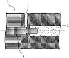
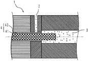
【0022】
図2は、溶融した樹脂原料3がゲート2を通って、金型1内部に充填された状態を示している。この状態では、ゲート2近傍に樹脂原料3が残留しており、取付孔を成形するピン4は金型1内に挿入されていない。なお、3aは樹脂原料に混入された金属粉であり、アルミなど金属の粉体、フレークなどが使用される。
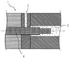
【0023】
次に、図3に示すように、ピン4が金型1内に移動すると、ピン4によりゲート2近傍に残留した樹脂原料3が金型1内部に押し込められる。すなわち、ゲート2近傍の樹脂原料3が排除され、ゲートカットが行われる。
【0024】
さらに、図4に示すように、ピン4が金型1内の所定の位置に移動すると、ピン4により取付孔が成形される。したがって、ピン4が樹脂原料3内に押し込まれ、取付孔が成形されるので、樹脂原料3の分流・合流が発生しない。その結果、ウェルドラインのない成形品が成形される。
【0025】
そして、図5に示すように、冷却後金型を離型すると、取付孔11が成形された把手10の成形品が完成する。なお、さらにピン4を金型1内にさらに移動することにより、離型を行ってもよい。また、樹脂原料3の充填やピン4の移動は、公知の射出成形装置で行うことができる。
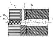
【0026】
図6は、本発明に係る他の成形方法を示す金型の要部概略断面図である。図において、取付孔を成形するピン4は、取付孔を成形する第1のピン41とゲート近傍に残留した樹脂原料を金型内に押し込み第2のピン42とに分割され、当該第1のピン41が第2のピン42に内挿され、互いに制限されずに金型1内部方向に移動できる構造としている。
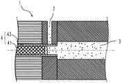
【0027】
図6に示すように、金型1内に樹脂原料3が充填された後、先ず、図7に示すように、第2のピン42が金型1内部に移動し、ゲート2近傍に残留した樹脂原料3が金型1内部に押し込められる。次に、図7に示すように、第1のピン41を金型1内部に移動し、取付孔が成形される。図5に示したように、冷却後金型を離型すると、取付孔11が成形された把手10の成形品が完成する。
【0028】
逆に、図9に示すように、先ず、第1のピン41を金型1内部に移動し、取付孔を成形した後、第2のピン42が金型1内部に移動し、ゲート2近傍に残留した樹脂原料3が金型1内部に押し込め、取付孔を成形してもよい。
【0029】
なお、成形の完了を示す図8では、図5に比べてピン4の押し込みの深さが浅いが、図5と同程度に押し込むことも可能であり、取付孔を成形する第1及び第2のピン41、42を押し込む深さを変化させることができるので、ピン4を交換することなく取付孔の深さの異なる成形品を成形することができる。
【発明の効果】
以上の通り、本発明の成形方法は、金型のゲートから溶融した合成樹脂原料を前記金型内に充填し、取付孔を成形するピンを金型内部方向に移動させ前記ゲート近傍に残留した前記樹脂原料を金型内に押し込み、さらに前記ピンを金型内部方向に移動させ前記取付孔を成形する方法であるので、取付孔の近傍にウェルドラインのない合成樹脂製把手を成形することができ、機械的強度に優れ、美観を損なうことのない把手を提供することができる。
【図面の簡単な説明】
【図1】図1(a)は本発明により成形される把手を、図1(b)は本発明により成形されるツマミをそれぞれ示す概略斜視図である。
【図2】本発明に係る成形方法を示す金型の要部概略断面図である。
【図3】本発明に係る成形方法を示す金型の要部概略断面図である。
【図4】本発明に係る成形方法を示す金型の要部概略断面図である。
【図5】本発明に係る成形方法を示す金型の要部概略断面図である。
【図6】本発明に係る他の成形方法を示す金型の要部概略断面図である。
【図7】本発明に係る他の成形方法を示す金型の要部概略断面図である。
【図8】本発明に係る他の成形方法を示す金型の要部概略断面図である。
【図9】本発明に係る他の成形方法を示す金型の要部概略断面図である。
【符号の説明】
1 金型
2 ゲート
3 樹脂原料
4 ピン
10 把手
11、21 取付孔
20 ツマミ
41 第1のピン
42 第2のピン[0001]
BACKGROUND OF THE INVENTION
The present invention relates to a method for forming a handle made of synthetic resin, and is used for doors and drawers of houses, furniture, home appliances and vehicles, transport containers such as baskets and tool boxes, or cooking utensils and tableware, In particular, the present invention relates to a method for molding a synthetic resin handle having a mounting hole used for building materials such as doors, sliding doors, hinged doors and drawers.
[0002]
[Prior art]
Synthetic resin handles (handles and knobs) are often attached to doors and drawers with metal bolts or nuts. For this reason, there is a problem in strength when the screw portion is formed of a synthetic resin. Therefore, after the handle is formed, a mounting hole for attaching a female screw or a male screw is provided. (For example, refer to Patent Document 1).
[0003]
Therefore, in a method for forming a synthetic resin handle having a mounting hole, a protrusion such as a pin for forming the mounting hole is provided in the mold, and a molten synthetic resin raw material is injected from the gate into the mold. Molding methods have been employed.
[0004]
[Patent Document 1]
Registered Utility Model No. 3045509 (first page, summary)
[0005]
[Problems to be solved by the invention]
In such a synthetic resin grip molding method of the prior art, the molten synthetic resin material injected from the gate is diverted by the projection for forming the mounting hole, wraps around the projection, and the resin material joins again. However, since the temperature of the resin raw material is lowered before joining, the joined resin raw materials are not sufficiently fused, so that a refuse mark called a weld line remains. Therefore, there is a problem that the mechanical strength of the handle decreases in the vicinity of the weld line.
[0006]
Moreover, when metallic resin such as aluminum powder is mixed and glossy metallic resin is used as a raw material, there is a problem that unevenness in gloss occurs and the appearance is impaired. Therefore, the gate position has to be determined so that the weld line is not conspicuous, and the degree of freedom in gate design is reduced. Further, after molding, post-processing called gate cut is required to remove the resin remaining in the vicinity of the gate.
[0007]
An object of the present invention is to provide a method for forming a synthetic resin handle that does not generate a weld line, and to provide a handle that has excellent mechanical strength and does not impair the appearance.
[0008]
[Means for Solving the Problems]
As a result of intensive studies to solve the above problems, the present invention is a method for forming a synthetic resin handle having a mounting hole.
Filling the mold with the synthetic resin material melted from the gate of the mold, moving the pin forming the mounting hole in the mold direction, and pushing the resin material remaining in the vicinity of the gate into the mold, and A synthetic resin grip molding method is adopted, in which the pin is moved inward of the mold to mold the mounting hole.
[0009]
After the molten resin material is filled in the mold, the gate is cut by moving the pin forming the mounting hole in the mold direction and pushing the resin material remaining in the vicinity of the gate into the mold. Further, the pin is moved toward the inside of the mold to form a mounting hole. Therefore, since the resin raw material is not shunted by protrusions such as pins, no weld line is generated in the vicinity of the mounting hole. Further, since the gate is cut at the time of molding, there is no need to remove the molded resin remaining in the vicinity of the gate by post-processing after molding.
[0010]
Moreover, in the molding method of the synthetic resin handle having a mounting hole,
The synthetic resin raw material melted from the gate of the mold is filled in the mold, the first pin is moved in the mold inner direction to form a mounting hole, and the mold inner direction with respect to the first pin A synthetic resin handle characterized in that a second pin externally movably moved is moved inward of the mold, the resin material remaining in the vicinity of the gate is pushed into the mold, and the mounting hole is formed. The molding method can also be adopted.
[0011]
Furthermore, in the molding method of the synthetic resin handle having a mounting hole,
The synthetic resin raw material melted from the gate of the mold is filled in the mold, the second pin is moved inward of the mold, the resin raw material remaining in the vicinity of the gate is pushed into the mold, and the second Also adopts a synthetic resin grip molding method, wherein the mounting hole is molded by moving the first pin inserted in the mold so as to be movable in the mold inner direction with respect to the two pins. it can.
[0012]
The pin for forming the mounting hole is divided into a first pin for forming the mounting hole and a resin raw material remaining in the vicinity of the gate into the mold, and the second pin is divided into the second pin. The structure is interpolated and can move toward the inside of the mold without being limited to each other.
[0013]
Therefore, first the first pin is moved inward of the mold to form the mounting hole, then the second pin is moved inward of the mold and the resin material remaining in the vicinity of the gate is pushed into the mold for mounting. Holes can be formed. On the contrary, first, the second pin is moved in the mold direction, the resin material remaining in the vicinity of the gate is pushed into the mold, and then the first pin is moved in the mold direction to form the mounting hole. You can also.
[0014]
Moreover, since the depth which pushes in the 1st and 2nd pin which shape | molds an attachment hole can be changed, the molded article from which the depth of an attachment hole differs can be shape | molded, without replacing | exchanging a pin.
[0015]
A synthetic resin grip molding method in which the synthetic resin grip is a synthetic resin grip for building materials can also be employed.
[0016]
When attached to building materials such as doors, sliding doors, hinged doors and drawers, a mechanical load is applied to the handle, particularly in the vicinity of the attachment hole, when the door is opened and closed. Since the handle formed by the present invention has no weld line and is excellent in mechanical strength, it can be suitably used as a handle for building materials.
[0017]
A synthetic resin grip forming method in which the synthetic resin raw material is a metallic resin can also be employed.
[0018]
A handle may be formed on the glossy metallic resin. The metallic resin is a resin in which a metal powder such as aluminum is mixed in a synthetic resin, and the metal powder has a gloss. When the weld line is generated, the gloss is uneven, which may impair the beauty. For this reason, the gate position is determined so that the weld line is not conspicuous. However, according to the method of the present invention, the necessity is eliminated, and the degree of freedom in gate design increases. As a result, more products can be molded simultaneously with one mold.
[0019]
In addition, the handle molded by the molding method of the present invention includes a generally U-shaped handle (handle) and a knob having a substantially circular shape attached to a hinged door or a drawer.
[0020]
DETAILED DESCRIPTION OF THE INVENTION
Hereinafter, an embodiment of a forming method according to the present invention will be described with reference to the drawings. FIG. 1 is a schematic perspective view showing a handle and a knob according to the present invention. FIG. 1A is a view showing a handle, and has attachment holes 11 at both ends of a substantially
[0021]
2 to 5 are schematic cross-sectional views of the main part of the mold showing the molding method according to the present invention, and show a part for molding the vicinity of the mounting hole. Although not shown in the drawing, in the case of a mold for forming the
[0022]
FIG. 2 shows a state in which the
[0023]
Next, as shown in FIG. 3, when the
[0024]
Further, as shown in FIG. 4, when the
[0025]
Then, as shown in FIG. 5, when the mold is released after cooling, a molded product of the
[0026]
FIG. 6 is a schematic cross-sectional view of a main part of a mold showing another molding method according to the present invention. In the figure, the
[0027]
As shown in FIG. 6, after the resin
[0028]
On the other hand, as shown in FIG. 9, first, the
[0029]
In FIG. 8 showing the completion of molding, the depth of pressing of the
【The invention's effect】
As described above, in the molding method of the present invention, the synthetic resin raw material melted from the gate of the mold is filled in the mold, and the pins for molding the mounting holes are moved inward of the mold and remain in the vicinity of the gate. Since the resin raw material is pushed into the mold and the pin is moved inward to mold the mounting hole, a synthetic resin handle without a weld line can be molded in the vicinity of the mounting hole. It is possible to provide a handle that has excellent mechanical strength and does not impair the beauty.
[Brief description of the drawings]
FIG. 1 (a) is a schematic perspective view showing a handle molded according to the present invention, and FIG. 1 (b) is a schematic perspective view showing a knob molded according to the present invention.
FIG. 2 is a schematic cross-sectional view of a main part of a mold showing a molding method according to the present invention.
FIG. 3 is a schematic cross-sectional view of a main part of a mold showing a molding method according to the present invention.
FIG. 4 is a schematic cross-sectional view of a main part of a mold showing a molding method according to the present invention.
FIG. 5 is a schematic cross-sectional view of a main part of a mold showing a molding method according to the present invention.
FIG. 6 is a schematic cross-sectional view of a main part of a mold showing another molding method according to the present invention.
FIG. 7 is a schematic cross-sectional view of a main part of a mold showing another molding method according to the present invention.
FIG. 8 is a schematic cross-sectional view of a main part of a mold showing another molding method according to the present invention.
FIG. 9 is a schematic cross-sectional view of a main part of a mold showing another molding method according to the present invention.
[Explanation of symbols]
1
Claims (4)
Translated fromJapanese金型のゲートから溶融した合成樹脂原料を前記金型内に充填し、第1のピンを金型内部方向に移動させ取付孔を成形し、さらに前記第1のピンに対して金型内部方向に移動可能に外挿された第2のピンを金型内部方向に移動させ前記ゲート近傍に残留した前記樹脂原料を金型内に押し込み前記取付孔を成形することを特徴とする合成樹脂製把手の成形方法。In the molding method of the synthetic resin handle having the mounting hole,
The synthetic resin raw material melted from the gate of the mold is filled in the mold,the first pin is moved in the mold inner direction to form a mounting hole, and the mold inner direction with respect to the first pin A synthetic resin handle characterized in that asecond pin externally movably moved is moved inward of the mold, the resin material remaining in the vicinity of the gate is pushed into the mold, and the mounting hole is formed. Molding method.
金型のゲートから溶融した合成樹脂原料を前記金型内に充填し、第2のピンを金型内部方向に移動させ前記ゲート近傍に残留した前記樹脂原料を金型内に押し込み、さらに前記第2のピンに対して金型内部方向に移動可能に内挿された第1のピンを金型内部方向に移動させ前記取付孔を成形することを特徴とする合成樹脂製把手の成形方法。In the molding method of the synthetic resin handle having the mounting hole,
The synthetic resin raw material melted from the gate of the mold is filled in the mold,the second pin is moved inward of the mold, the resin raw material remaining in the vicinity of the gate is pushed into the mold, and the second A method for molding a synthetic resin handle, wherein the mounting hole is formed bymoving a first pin, which is inserted in the mold so as to be movable in the mold inner direction, with respect to the two pins .
Priority Applications (3)
| Application Number | Priority Date | Filing Date | Title |
|---|---|---|---|
| JP2002357240AJP3705595B2 (en) | 2002-12-09 | 2002-12-09 | Molding method of synthetic resin handle |
| CN 03150400CN1283441C (en) | 2002-12-09 | 2003-07-30 | Forming method for synthetic resin handle |
| HK04106277.7AHK1063451B (en) | 2002-12-09 | 2004-08-23 | Molding method of a handle made of synthetic resin |
Applications Claiming Priority (1)
| Application Number | Priority Date | Filing Date | Title |
|---|---|---|---|
| JP2002357240AJP3705595B2 (en) | 2002-12-09 | 2002-12-09 | Molding method of synthetic resin handle |
Publications (2)
| Publication Number | Publication Date |
|---|---|
| JP2004188678A JP2004188678A (en) | 2004-07-08 |
| JP3705595B2true JP3705595B2 (en) | 2005-10-12 |
Family
ID=32757331
Family Applications (1)
| Application Number | Title | Priority Date | Filing Date |
|---|---|---|---|
| JP2002357240AExpired - LifetimeJP3705595B2 (en) | 2002-12-09 | 2002-12-09 | Molding method of synthetic resin handle |
Country Status (2)
| Country | Link |
|---|---|
| JP (1) | JP3705595B2 (en) |
| CN (1) | CN1283441C (en) |
Families Citing this family (9)
| Publication number | Priority date | Publication date | Assignee | Title |
|---|---|---|---|---|
| JP2010251712A (en) | 2009-03-26 | 2010-11-04 | Sony Corp | Bi-section type semiconductor laser device, manufacturing method thereof, and driving method of bi-section type semiconductor laser device |
| JP2011187579A (en) | 2010-03-05 | 2011-09-22 | Sony Corp | Mode-locked semiconductor laser element and driving method thereof |
| JP2011187580A (en) | 2010-03-05 | 2011-09-22 | Sony Corp | Self-oscillation type semiconductor laser element and driving method of the same |
| JP5138023B2 (en) | 2010-12-08 | 2013-02-06 | ソニー株式会社 | Semiconductor laser element |
| JP2012151210A (en) | 2011-01-18 | 2012-08-09 | Sony Corp | Semiconductor laser device |
| CN102322176A (en)* | 2011-06-30 | 2012-01-18 | 厦门建霖工业有限公司 | Method for preparing imitation metal composite door handle |
| KR101566245B1 (en)* | 2014-06-17 | 2015-11-05 | (주)태양프라스틱 | Knob of apparatus for folding the automobile seat and method of manufacturing it |
| DE102019210375A1 (en)* | 2019-07-12 | 2021-01-14 | Continental Teves Ag & Co. Ohg | Method of manufacturing a robust sensor |
| CN118493737B (en)* | 2024-06-04 | 2024-11-19 | 深圳市精森源科技有限公司 | An integrated automobile door handle high-efficiency injection molding machine and injection molding process |
- 2002
- 2002-12-09JPJP2002357240Apatent/JP3705595B2/ennot_activeExpired - Lifetime
- 2003
- 2003-07-30CNCN 03150400patent/CN1283441C/ennot_activeExpired - Lifetime
Also Published As
| Publication number | Publication date |
|---|---|
| JP2004188678A (en) | 2004-07-08 |
| CN1283441C (en) | 2006-11-08 |
| HK1063451A1 (en) | 2004-12-31 |
| CN1506212A (en) | 2004-06-23 |
Similar Documents
| Publication | Publication Date | Title |
|---|---|---|
| JP3705595B2 (en) | Molding method of synthetic resin handle | |
| CA2523902A1 (en) | Container with hinged lids and method of molding the container and assembling the hinged lids on the container in the molding process | |
| EP0624447B1 (en) | Method for manufacturing synthetic resin containers | |
| CA2375668A1 (en) | Mould with turnable middle section | |
| US4762379A (en) | Blow molded panels and a mold and method of making them | |
| WO2006071113A3 (en) | Method and apparatus for manufacturing products | |
| CN206242383U (en) | Workpiece Double-color forming die | |
| JP3616936B2 (en) | Synthetic resin handle member and manufacturing method thereof | |
| WO2006039309A3 (en) | A molded, plastic container and a method for making the same | |
| JP2014004737A (en) | Method for injection molding of resin and injection-molded article of resin | |
| HK1063451B (en) | Molding method of a handle made of synthetic resin | |
| WO1997038840A1 (en) | Two-material moulding | |
| JP3484421B2 (en) | Hollow molding method and apparatus for three-dimensional bent product | |
| WO2011095490A3 (en) | Molding tool for producing molded parts made of plastic, for example, in particular made of a fiber composite material | |
| JP2919603B2 (en) | Molding method for lid-formed products | |
| JP5453051B2 (en) | Manufacturing method of resin products | |
| JP2672733B2 (en) | Mold for molding and molding method | |
| DE60105083T2 (en) | A method of manufacturing a plastic door for home electric appliances and door made by the method | |
| KR100580807B1 (en) | Discontinuous molding of plastics, apparatus for carrying out such methods, and parts made by such methods or apparatus | |
| JP4047648B2 (en) | Sandwich molding method | |
| CN212147318U (en) | Complicated three-plate structure injection mold | |
| CN218576882U (en) | Fruit and vegetable box decorative plate mold | |
| CN212554876U (en) | Gate shearing device for air door injection molding part | |
| US20050112224A1 (en) | Methods and apparatuses for the formation of blow molded objects | |
| JP2004230794A (en) | Injection molding method and its molding mold |
Legal Events
| Date | Code | Title | Description |
|---|---|---|---|
| A977 | Report on retrieval | Free format text:JAPANESE INTERMEDIATE CODE: A971007 Effective date:20050117 | |
| A131 | Notification of reasons for refusal | Free format text:JAPANESE INTERMEDIATE CODE: A131 Effective date:20050121 | |
| A521 | Request for written amendment filed | Free format text:JAPANESE INTERMEDIATE CODE: A523 Effective date:20050322 | |
| A131 | Notification of reasons for refusal | Free format text:JAPANESE INTERMEDIATE CODE: A131 Effective date:20050602 | |
| A521 | Request for written amendment filed | Free format text:JAPANESE INTERMEDIATE CODE: A523 Effective date:20050606 | |
| TRDD | Decision of grant or rejection written | ||
| A01 | Written decision to grant a patent or to grant a registration (utility model) | Free format text:JAPANESE INTERMEDIATE CODE: A01 Effective date:20050627 | |
| A61 | First payment of annual fees (during grant procedure) | Free format text:JAPANESE INTERMEDIATE CODE: A61 Effective date:20050725 | |
| R150 | Certificate of patent or registration of utility model | Ref document number:3705595 Country of ref document:JP Free format text:JAPANESE INTERMEDIATE CODE: R150 Free format text:JAPANESE INTERMEDIATE CODE: R150 | |
| FPAY | Renewal fee payment (event date is renewal date of database) | Free format text:PAYMENT UNTIL: 20110805 Year of fee payment:6 | |
| R250 | Receipt of annual fees | Free format text:JAPANESE INTERMEDIATE CODE: R250 | |
| FPAY | Renewal fee payment (event date is renewal date of database) | Free format text:PAYMENT UNTIL: 20170805 Year of fee payment:12 | |
| R250 | Receipt of annual fees | Free format text:JAPANESE INTERMEDIATE CODE: R250 | |
| R250 | Receipt of annual fees | Free format text:JAPANESE INTERMEDIATE CODE: R250 | |
| R250 | Receipt of annual fees | Free format text:JAPANESE INTERMEDIATE CODE: R250 | |
| R250 | Receipt of annual fees | Free format text:JAPANESE INTERMEDIATE CODE: R250 | |
| R250 | Receipt of annual fees | Free format text:JAPANESE INTERMEDIATE CODE: R250 | |
| R250 | Receipt of annual fees | Free format text:JAPANESE INTERMEDIATE CODE: R250 | |
| R250 | Receipt of annual fees | Free format text:JAPANESE INTERMEDIATE CODE: R250 | |
| EXPY | Cancellation because of completion of term |