JP3704887B2 - Fault diagnosis device for internal combustion engine - Google Patents
Fault diagnosis device for internal combustion engineDownload PDFInfo
- Publication number
- JP3704887B2 JP3704887B2JP13133997AJP13133997AJP3704887B2JP 3704887 B2JP3704887 B2JP 3704887B2JP 13133997 AJP13133997 AJP 13133997AJP 13133997 AJP13133997 AJP 13133997AJP 3704887 B2JP3704887 B2JP 3704887B2
- Authority
- JP
- Japan
- Prior art keywords
- fuel
- amount
- common rail
- fuel pressure
- injection amount
- Prior art date
- Legal status (The legal status is an assumption and is not a legal conclusion. Google has not performed a legal analysis and makes no representation as to the accuracy of the status listed.)
- Expired - Fee Related
Links
Images


Classifications
- Y—GENERAL TAGGING OF NEW TECHNOLOGICAL DEVELOPMENTS; GENERAL TAGGING OF CROSS-SECTIONAL TECHNOLOGIES SPANNING OVER SEVERAL SECTIONS OF THE IPC; TECHNICAL SUBJECTS COVERED BY FORMER USPC CROSS-REFERENCE ART COLLECTIONS [XRACs] AND DIGESTS
- Y02—TECHNOLOGIES OR APPLICATIONS FOR MITIGATION OR ADAPTATION AGAINST CLIMATE CHANGE
- Y02T—CLIMATE CHANGE MITIGATION TECHNOLOGIES RELATED TO TRANSPORTATION
- Y02T10/00—Road transport of goods or passengers
- Y02T10/10—Internal combustion engine [ICE] based vehicles
- Y02T10/12—Improving ICE efficiencies
Landscapes
- Fuel-Injection Apparatus (AREA)
- Electrical Control Of Air Or Fuel Supplied To Internal-Combustion Engine (AREA)
- Combined Controls Of Internal Combustion Engines (AREA)
Description
Translated fromJapanese【0001】
【発明の属する技術分野】
本発明は内燃機関の故障診断装置に関する。
【0002】
【従来の技術】
吐出量可変の燃料供給ポンプから吐出された加圧燃料をコモンレール内に供給し、コモンレール内に供給された加圧燃料を各気筒の燃料噴射弁に分配供給し、コモンレール内の燃料圧を燃料圧センサにより検出してコモンレール内の燃料圧が目標燃料圧となるように燃料供給ポンプの吐出量を制御するようにした内燃機関において、燃料圧センサの出力電圧が通常ではとり得ない極度に低い電圧或いは極度に高い電圧となったときには燃料圧センサが故障したと判断し、コモンレール内の燃料圧をオープンループ制御するようにした内燃機関が公知である(特開平4−272445号公報参照)。
【0003】
【発明が解決しようとする課題】
しかしながら燃料圧センサの故障の中には燃料圧センサの出力電圧が単に正規の出力電圧からずれるだけであって通常とり得る電圧の範囲内にある故障もあり、このような故障を生じた場合には上記内燃機関におけるような簡単な方法では燃料圧センサの故障を見付け出すことはできない。
【0004】
【課題を解決するための手段】
そこで1番目の発明では、吐出量可変の燃料供給ポンプから吐出された加圧燃料をコモンレール内に供給し、コモンレール内に供給された加圧燃料を各気筒の燃料噴射弁に分配供給し、コモンレール内の燃料圧を燃料圧センサにより検出してコモンレール内の燃料圧が目標燃料圧となるように燃料供給ポンプの吐出量を制御するようにした内燃機関において、質量流量検出器により検出された吸入空気の質量流量と空燃比センサにより検出された空燃比から各燃料噴射弁より実際に噴射された実噴射量を検出する実噴射量検出手段と、各燃料噴射弁から噴射すべき燃料量の指令値と実噴射量検出手段により検出された実噴射量との差、燃料圧センサにより検出された燃料圧変化、および機関回転数の変動量に基づいて燃料が実際に漏洩しているか或いは燃料圧センサが故障しているか否かを判断する判断手段とを具備し、この判断手段は、実噴射量が噴射すべき燃料量の指令値よりも予め定められた噴射量以上多くかつ機関回転数の変動量が予め定められた変動量よりも小さいときには燃料圧センサが故障していると判断し、実噴射量が噴射すべき燃料量の指令値よりも予め定められた噴射量以上多くかつ機関回転数の変動量が予め定められた変動量よりも大きいときには燃料が燃料噴射弁から燃焼室内に漏洩していると判断する。
また、2番目の発明では1番目の発明において、判断手段は、燃料圧センサにより検出された燃料噴射前後における燃料圧変化と、燃料噴射量に基づき算出された燃料噴射による燃料圧変化の予測値とに基づいて燃料がコモンレールから又は燃料供給ポンプよりコモンレールを経て燃料噴射弁に至る配管から漏洩しているか否かを判断し、実噴射量が噴射すべき燃料量の指令値よりも予め定められた燃料量以上少なくかつ燃料がコモンレール又は配管から漏洩していないと判断されたときには燃料圧センサが故障していると判断し、実噴射量が噴射すべき燃料量の指令値とほぼ同じか又は指令値よりも少なくかつ燃料がコモンレール又は配管から漏洩していると判断されたときには燃料が実際にコモンレール又は配管から漏洩していると判断する。
【0010】
【発明の実施の形態】
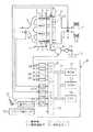
図1を参照すると、1はディーゼル機関本体、2は各気筒の燃焼室、3は各燃焼室2内に向けて燃料を噴射するための電気制御式燃料噴射弁を夫々示す。各燃焼室2は対応する吸気枝管4を介して共通のサージタンク5に接続され、サージタンク5は吸気ダクト6を介してエアクリーナ7に連結される。吸気ダクト6内には質量流量検出器8が配置される。また、各燃焼室2は共通の排気マニホルド9に連結され、排気マニホルド9の集合部には空燃比センサ10が配置される。
【0011】
各燃料噴射弁3は対応する燃料供給管11を介して共通の燃料リザーバ、いわゆるコモンレール12に連結される。燃料タンク13内の燃料は低圧ポンプ14により吐出量可変の燃料供給ポンプ、即ち電気制御式高圧ポンプ15に供給され、高圧ポンプ15から吐出された加圧燃料がコモンレール12内に供給される。コモンレール12内の加圧燃料は燃料供給管11を介して各燃料噴射弁3に分配供給され、各燃料噴射弁3から対応する燃焼室2内に噴射される。コモンレール12の一端部には燃料圧センサ16が取付けられる。
【0012】
電子制御ユニット20はディジタルコンピュータからなり、双方向性バス21を介して相互に接続されたROM(リードオンリメモリ)22、RAM(ランダムアクセスメモリ)23、CPU(マイクロプロセッサ)24、入力ポート25および出力ポート26を具備する。質量流量検出器8は各気筒に供給される吸入空気の質量流量に比例した出力電圧を発生し、この出力電圧が対応するAD変換器27を介して入力ポート25に入力される。燃料圧センサ16はコモンレール12内の燃料圧に比例した出力電圧を発生し、この出力電圧が対応するAD変換器27を介して入力ポート25に入力される。
【0013】
また、空燃比センサ10の出力信号が対応するAD変換器27を介して入力ポート25に入力される。アクセルペダル30にはアクセルペダル30の踏込み量に比例した出力電圧を発生する負荷センサ31が接続され、負荷センサ31の出力電圧は対応するAD変換器27を介して入力ポート25に入力される、クランク角センサ32はクランクシャフトが例えば30°回転する毎に出力パルスを発生し、この出力パルスは入力ポート25に入力される。この出力パルスから各気筒のクランク角および機関回転数が算出される。一方、出力ポート26は対応する駆動回路28を介して高圧ポンプ15および各燃料噴射弁3に接続される。
【0014】
燃料噴射量Qは機関回転数Nおよびアクセルペダル30の踏込み量から定まり、これらの関係が図2に示されている。なお、図2において各実線はアクセルペダル30の同一踏込み量(最大踏込み量に対するパーセンテージで示されている)を表わしている。
コモンレール12内の目標燃料圧Pcは機関回転数Nおよび燃料噴射量Qから定まり、これらの関係が図3に示されている。図1に示される実施例では燃料圧センサ16により検出されたコモンレール12内の燃料圧が図3に示される目標燃料圧Pcとなるように高圧ポンプ15の吐出量が制御される。
【0015】
各燃料噴射弁3から噴射すべき燃料量Qの指令値は出力ポート26に出力され、出力ポート26に出力された噴射量Qの指令値に基づいて各燃料噴射弁3から燃料が噴射される。燃料噴射弁3および燃料圧センサ16が正常に作動しておりかつコモンレール12から燃料が漏洩していない限り、噴射量Qの指令値に基づいて各燃料噴射弁3から燃料噴射を行うと各燃料噴射弁3から噴射される燃料量Qは図2に示される燃料量となる。なお、この燃料量Qの指令値は実際には噴射時間で与えられており、この噴射時間TPは図4に示されるように噴射量Qおよび機関回転数Nの関数としてマップの形で予めROM22内に記憶されている。しかしながら発明を理解しやすくするために本願明細書では、噴射量Qの指令値というときは図2に示される噴射量を表わしているものとする。
【0016】
ところで燃料圧センサ16の出力信号が異常となるか、或いはコモンレール12から燃料が漏洩すると実際の噴射量が噴射量Qの指令値と異なってしまい、意図した燃焼が得られるなく。従って燃料圧センサ16の出力信号が異常になったか否か、或いはコモンレール12から燃料が漏洩しているか否かをできるだけ早く検出する必要がある。ところが燃料圧センサ16の出力信号が異常になっても、コモンレール12から燃料が漏洩しても燃料噴射量に同様な変化が表われ、これらを簡単に区別することはできない。そこで本発明による実施例では噴射量Qの指令値と実噴射量との差、およびコモンレール12からの燃料漏れの判定、および機関回転数の変動から燃料圧センサ16の出力信号が異常になっているか否か、或いはコモンレール12から燃料が漏洩しているか否かを判断するようにしている。
【0017】
下に示す表1は故障形態をNo. 1からNo. 4の4つの形態に分類し、各故障形態における燃料噴射量の変化、燃料漏れの判定および機関回転数の変動を示している。
【0018】
【表1】
次にこの表1に従って各故障形態から順次説明する。
まず始めに故障形態No. 1およびNo. 2について説明する。図5(A)の実線Xは燃料圧センサ16が正常に作動しているときの燃料圧センサ16の出力電圧Vとコモンレール12内の燃料圧Pcとの関係を示している。これに対して図5(B)はゲインが変化することによって出力電圧Vが正常値Xからずれた場合(YおよびZ)を示しており、図5(C)は零点がドリフトすることによって出力電圧Vが正常値Xからずれた場合(YおよびZ)を示している。
【0020】
図5(B)および図5(C)のYで示される場合には同一の燃料圧Pcに対して出力電圧Vが正常値Xよりも低くなっており、この場合が表1の故障形態No. 1である。一方、図5(B)および図5(C)のZで示される場合には同一の燃料圧Pcに対して出力電圧Vが正常値Xよりも高くなっており、この場合が表1の故障形態No. 2である。即ち、表1の故障形態No. 1およびNo. 2は燃料圧センサ16が故障した場合を示している。
【0021】
一方、表1の故障形態No. 3およびNo. 4はコモンレール12からの燃料漏れが発生している場合を示している。即ち、故障形態No. 3はコモンレール12から、或いはコモンレール12と高圧ポンプ15間の配管等から外部に燃料が漏洩している場合を示している。これに対して故障形態No. 4は燃料噴射弁3から燃焼室2内に燃料が漏洩している場合を示している。例えばいずれかの燃料噴射弁3が開弁し放しとなって燃料が噴射され放しになるような場合である。
【0022】
次に表1の燃料噴射量の欄について説明する。この欄では噴射量Qの指令値と実噴射量とが比較される。そこでまず初めに実噴射量の算出方法について説明する。図6は空燃比センサ10の出力電流Iと空燃比A/Fとの関係を示している。図6に示されるように空燃比センサ10の出力電流Iは空燃比A/Fに応じて変化し、従って空燃比センサ10の出力電流Iから空燃比A/Fを検出することができる。一方、各気筒内に供給される吸入空気の質量流量は質量流量検出器8により検出されており、この質量流量検出器8により検出された吸入空気の質量流量と空燃比センサ10により検出された空燃比A/Fから実噴射量が算出される。
【0023】
故障形態No. 1では燃料圧センサ16の出力電圧Vが正常値よりも低くなっている。このときこの低い出力電圧Vに基いてコモンレール12内の燃料圧が図3に示される目標燃料圧Pcに制御されるのでコモンレール12内の燃料圧は目標燃料圧Pcよりも高くなる。その結果、燃料噴射量が正規の噴射量よりも多くなるために実噴射量が噴射量Qの指令値よりも大きくなる。
【0024】
一方、故障形態No. 2では燃料圧センサ16の出力電圧Vが正常値よりも高くなっている。このときこの高い出力電圧Vに基いてコモンレール12内の燃料圧が図3に示される目標燃料圧Pcに制御されるのでコモンレール12内の燃料圧は目標燃料圧Pcよりも低くなる。その結果、燃料噴射量が正規の噴射量よりも少なくなるために実噴射量が噴射量Qの指令値よりも小さくなる。
【0025】
故障形態No. 3は例えばコモンレール12から燃料が外部に漏洩している場合である。コモンレール12から燃料が漏洩すると燃料圧センサ16の出力信号に基づいてコモンレール12内の燃料圧が目標燃料圧となるように高圧ポンプ15から燃料が補給される。従って高圧ポンプ15から燃料が補給されるまでの間はコモンレール12内の燃料圧は目標燃料圧Pcよりも若干低くなっており、従って故障形態No. 3では実噴射量が噴射量Qの指令値とほぼ同じか、噴射量Qの指令値よりも少しばかり小さくなっている。
【0026】
故障形態No. 4では例えばいずれかの気筒の燃料噴射弁3から燃料が吹き放しになる。従ってこのときには実噴射量が噴射量Qの指令値よりも大きくなる。
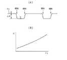
次に表1の漏れ判定の欄について説明する。図7(A)はコモンレール12から燃料が漏洩していないときのコモンレール12内の燃料圧Pcの変化を示している。図7(A)に示されるように噴射が行われるとコモンレール12内の燃料圧PcがΔPだけ低下し、次いで暫らくすると低下した燃料分だけ燃料が高圧ポンプ15からコモンレール12内に供給される。
【0027】
上述したように噴射が行われるとコモンレール12内の燃料圧PcがΔPだけ低下する。この低下量ΔPは次式に基づいて噴射量Qから予測することもできる。
ΔP=(ΔV/V)・K
上式は体積変化ΔVと圧力変化ΔPとの関係を示す一般式であってVは全体の体積を示し、Kは体積弾性率を示している。上式をコモンレール12内の圧力変化に適用するとVはコモンレール12の容積、ΔVは噴射量Q、ΔPは噴射による燃料圧低下量の予測値を表わすことになる。なお、図7(B)に示されるように体積弾性率Kはコモンレール12内の燃料圧Pcが高くなるにつれて大きくなる。本発明による実施例では図7(A)において噴射前のa点における燃料圧を燃料圧センサ16により検出すると共に噴射後におけるb点における燃料圧を燃料圧センサ16により検出し、これらの燃料圧の差を低下量の実測値ΔPとしている。コモンレール12からの燃料漏れがない場合には実測値ΔPと予測値ΔPとはほぼ等しくなり、これに対して燃料漏れが発生すると実測値ΔPが予測値ΔPよりも大きくなる。このことを利用してコモンレール12からの燃料漏れの判定を行っている。
【0028】
図8(A),(B),(C)において破線は燃料圧センサ16が正常でありかつコモンレール12からの燃料漏れがないときの噴射前後におけるコモンレール12内の燃料圧の変化を示している。
一方、図8(A)において実線は故障形態No. 1のときの噴射前後におけるコモンレール12内の燃料圧の変化を示している。故障形態No. 1のときには前述したようにコモンレール12内の燃料圧が目標燃料圧よりも高くなっている。コモンレール12内の燃料圧が高くなっていると体積弾性率Kが大きくなり、斯くしてこのとき実線で示される燃料圧低下量の実測値ΔPは破線で示される燃料圧低下量とほぼ等しい予測値ΔPよりも大きくなる。従ってこの場合にはコモンレール12からの燃料漏れが生じていないにもかかわらずに燃料漏れが生じていると判断される。
【0029】
一方、図8(B)において実線は故障形態No. 2のときの噴射前後におけるコモンレール12内の燃料圧の変化を示している。故障形態No. 2のときには前述したようにコモンレール12内の燃料圧が目標燃料圧よりも低くなる。コモンレール12内の燃料圧が低くなると体積弾性率Kが小さくなり、斯くしてこのとき実線で示される燃料圧低下量の実測値ΔPは破線で示される燃料圧低下量とほぼ等しい予測値ΔPよりも小さくなる。従ってこの場合にはコモンレール12からの燃料漏れが生じていないと判断される。
【0030】
一方、図8(C)の実線は故障形態No. 3およびNo. 4のときの噴射前後におけるコモンレール12内の燃料圧変化を示している。燃料漏れを生じているときにはコモンレール12内の燃料圧は燃料が補給されるまで低下し続け、斯くしてこのとき実線で示される燃料圧低下量の実測値ΔPは破線で示される燃料圧低下量とほぼ等しい予測値ΔPよりも大きくなる。従ってこの場合にはコモンレール12からの燃料漏れが生じていると判断される。
【0031】
次に表1の回転変動の欄について説明する。本発明による実施例ではクランク角センサ32の出力信号に基づいて各気筒の爆発上死点から爆発下死点までの180クランク角度の経過時間が算出され、爆発行程が連続する二つの気筒間における経過時間差から回転数変動量が求められる。図9には経過時間の変化の二つのパターンAおよびBが示されている。なお、図9において#1,#2,#3,#4は夫々1番気筒、2番気筒、3番気筒、4番気筒を示している。
【0032】
故障形態No. 1のように実噴射量が噴射量Qの指令値より多い場合であっても、故障形態No. 2のように実噴射量が噴射量Qの指令値より少ない場合であっても各燃料噴射弁3から噴射される燃料量にはほとんどばらつきがない。また、コモンレール12から燃料が漏洩している場合であっても故障形態No. 3のように外部に燃料が漏洩している場合には各燃料噴射弁3から噴射される燃料量にはほとんどばらつきがない。従って故障形態No. 1からNo. 3の場合には爆発行程の経過時間が図9のAのように変化し、機関回転数の変動量は極めて小さくなる。
【0033】
これに対して故障形態No. 4のようにいずれか一つの燃料噴射弁3から燃料が吹き放しになった場合には燃料が吹き放しになっている気筒の爆発行程の経過時間のみが他の気筒の経過時間に比べて短かくなる。図9のBは3番気筒#3の燃料噴射弁3から燃料が吹き放しになった場合を示している。この場合には爆発行程が連続する気筒間、例えば1番気筒#1と3番気筒#3間の経過時間の差が大きくなり、斯くして機関回転数の変動量が大きくなる。
【0034】
表1において故障形態No. 1とNo. 4ではいずれも実噴射量が噴射量Qの指令値よりも多くなるが故障形態No. 1では回転変動が正常な小さな範囲にあるのに対して故障形態No. 4では回転変動が大きくなる。即ち、故障形態No. 1とNo.4を比較するに当って回転変動の大きさが実際にコモンレール12から燃料が漏洩しているか否かの判断の基準となっている。即ち、実噴射量が噴射量Qの指令値よりも多い場合において回転変動が小さければ実際に燃料が漏洩していないと判断され、従ってこの場合には燃料圧センサ16が故障していると判断される。これに対し実噴射量が噴射量Qの指令値よりも多い場合において回転変動が大きければ実際に燃料が漏洩していると判断され、従ってこの場合には燃料噴射弁3から燃焼室2内に燃料が漏洩していると判断される。
【0035】
一方、実噴射量が噴射量Qの指令値よりも少ない場合には故障形態がNo. 2かNo. 3のいずれかの故障が発生していることになる。この場合、コモンレール12から燃料が漏洩していないと判断されたときには燃料圧センサ16が故障していると判断され、コモンレール12から燃料が漏洩しているときにはコモンレール12から燃料が外部に漏洩していると判断される。また、実噴射量と噴射量Qの指令値とがほぼ等しくても燃料漏れがあると判断された場合にはコモンレール12から燃料が外部に漏洩していると判断される。
【0036】
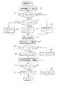
図10に異常判定ルーチンを示す。図10を参照するとまず初めにステップ40において実噴射量Qrが算出される。次いでステップ41では実噴射量Qrが噴射量Qの指令値に一定値αを加算した値(Q+α)よりも大きいか否かが判別される。Q+α<Qrのときにはステップ42に進んでQ+α<Qrであることを示すフラグQ1がセットされる。一方、Q+α≧Qrのときにはステップ43に進んで実噴射量Qrが噴射量Qの指令値から一定値αを減算した値(Q−α)よりも小さいか否かが判別される。Q−α>Qrのときにはステップ44に進んでQ−α>Qrであることを示すフラグQ2がセットされる。これに対してQ−α≦Qrのときにはステップ45に進んでフラグQ1,Q2がリセットされる。
【0037】
ステップ46では燃料圧センサ16の出力信号に基づいてコモンレール12内の燃料圧低下量の実測値ΔPが算出される。次いでステップ47では噴射量Qおよび体積弾性率Kを用いてコモンレール12内の燃料圧低下量の予測値Pd(=予測値ΔP)が算出される。次いでステップ48では実測値ΔPが予測値Pdに一定値βを加算した値(Pd+β)よりも大きいか否かが判別される。ΔP>Pd+βのときにはステップ49に進んで燃料が漏洩していることを示すフラグLがセットされる。これに対してΔP≦Pd+βのときにはステップ50に進んでフラグLがリセットされる。
【0038】
ステップ51では爆発行程が連続する二つの気筒間の爆発行程の経過時間差の平均値である回転数変動値Fが算出される。次いでステップ52では回転数変動値Fが設定値F0よりも大きいか否かが判別される。F>F0のときにはステップ53に進んで回転変動が大きいことを示すフラグFがセットされる。これに対してF≦F0のときにはステップ54に進んでフラグFがリセットされる。
【0039】
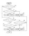
図11に故障判定ルーチンを示す。図11を参照するとステップ60においてフラグQ1がセットされているか否かが判別される。フラグQ1がセットされているときにはステップ61に進んでフラグFがセットされているか否かが判別される。フラグFがセットされていないときにはステップ62に進んで燃料圧センサ16が故障していると判断される。これに対してフラグFがセットされているときにはステップ63に進んでコモンレール12内から燃焼室2内に燃料が漏洩していると判断される。
【0040】
一方、ステップ60においてフラグQ1がセットされていないと判断されたときにはステップ64に進んでフラグQ2がセットされているか否かが判別される。フラグQ2がセットされているときにはステップ65に進んでフラグLがセットされているか否かが判別される。フラグLがセットされていないときにはステップ66に進んで燃料圧センサ16が故障していると判断される。これに対してフラグLがセットされているときにはステップ67に進んでコモンレール12内から外部に燃料が漏洩していると判断される。
【0041】
一方、ステップ64においてフラグQ2がセットされていないと判別されたときにはステップ68に進んでフラグLがセットされているか否かが判別される。フラグLがセットされているときにはステップ67に進んでコモンレール12内から外部に燃料が漏洩していると判断される。
【0042】
【発明の効果】
燃料圧センサが故障したことを確実に検出することができる。
【図面の簡単な説明】
【図1】ディーゼル機関の全体図である。
【図2】燃料・噴射量Qを示す図である。
【図3】コモンレール内の目標燃料圧を示す図である。
【図4】噴射時間TPのマップを示す図である。
【図5】燃料圧センサの出力電圧を示す図である。
【図6】空燃比センサの出力を示す図である。
【図7】コモンレール内の燃料圧変化を示す図である。
【図8】コモンレール内の燃料圧変化を示す図である。
【図9】各気筒の爆発行程の経過時間を示す図である。
【図10】異常判定を行うためのフローチャートである。
【図11】故障判定を行うためのフローチャートである。
【符号の説明】
2…燃焼室
3…燃料噴射弁
12…コモンレール
16…燃料圧センサ[0001]
BACKGROUND OF THE INVENTION
The present invention relates to an internal combustion engine failure diagnosis apparatus.
[0002]
[Prior art]
Pressurized fuel discharged from a variable delivery fuel supply pump is supplied into the common rail, the pressurized fuel supplied into the common rail is distributed and supplied to the fuel injection valves of each cylinder, and the fuel pressure in the common rail is adjusted to the fuel pressure. In an internal combustion engine in which the fuel supply pump discharge amount is controlled so that the fuel pressure in the common rail becomes the target fuel pressure detected by the sensor, the output voltage of the fuel pressure sensor is an extremely low voltage that cannot normally be taken Alternatively, an internal combustion engine in which it is determined that the fuel pressure sensor has failed when the voltage becomes extremely high and the fuel pressure in the common rail is controlled in an open loop is known (see Japanese Patent Laid-Open No. 4-272445).
[0003]
[Problems to be solved by the invention]
However, some of the fuel pressure sensor failures are such that the output voltage of the fuel pressure sensor simply deviates from the normal output voltage and is within the normal voltage range. It is not possible to find a failure of the fuel pressure sensor by a simple method as in the internal combustion engine.
[0004]
[Means for Solving the Problems]
Accordingly, in the first aspect of the invention, the pressurized fuel discharged from the fuel supply pump having a variable discharge amount is supplied into the common rail, the pressurized fuel supplied into the common rail is distributed and supplied to the fuel injection valves of each cylinder, and the common rail is supplied. in an internal combustion engine which is adapted to control the discharge amount of the fuel supply pump to the fuel pressure detected by the fuel pressure sensor is a fuel pressure in the common rail becomes a target fuel pressure of the inner,which is detected by the mass flow detector inhalation An actual injection amount detecting means for detecting the actual injection amount actually injected from each fuel injection valve from the air mass flow rate and the air-fuel ratio detected by the air-fuel ratio sensor, and a command for the fuel amount to be injected from each fuel injection valve The fuel actually leaks based on the difference between the value and the actual injection amount detected by the actual injection amount detection means, the change in the fuel pressure detected by the fuel pressure sensor, and the amount of fluctuation in the engine speed. Or determining means for determining whether or not the fuel pressure sensor is malfunctioning. The determining means has an actual injection amount larger than a command value for the amount of fuel to be injected and more than a predetermined injection amount and When the fluctuation amount of the engine speed is smaller than the predetermined fluctuation amount, it is determined that the fuel pressure sensor has failed, and the actual injection amount is equal to or greater than the predetermined injection amount than the command value of the fuel amount to be injected. When the amount of fluctuation in the engine speed is larger than a predetermined fluctuation amount, it is determined that fuel is leaking from the fuel injection valve into the combustion chamber.
In the second invention, in the first invention, the judging means is a fuel pressure change detected before and after the fuel injection detected by the fuel pressure sensor, and a predicted value of the fuel pressure change by the fuel injection calculated based on the fuel injection amount. Based on the above, it is determined whether fuel is leaking from the common rail or from the fuel supply pump through the common rail to the fuel injection valve, and the actual injection amount is determined in advance from the command value of the fuel amount to be injected. When it is determined that the amount of fuel is less than the amount of fuel and the fuel is not leaking from the common rail or the pipe, it is determined that the fuel pressure sensor has failed, and the actual injection amount is substantially the same as the command value of the fuel amount to be injected or When it is determined that the fuel is leaking from the common rail or piping that is less than the command value, it is determined that the fuel is actually leaking from the common rail or piping. That.
[0010]
DETAILED DESCRIPTION OF THE INVENTION
Referring to FIG. 1,
[0011]
Each
[0012]
The
[0013]
Further, the output signal of the air-
[0014]
The fuel injection amount Q is determined from the engine speed N and the depression amount of the
The target fuel pressure Pc in the
[0015]
The command value of the fuel amount Q to be injected from each
[0016]
When the output signal of the
[0017]
Table 1 shown below classifies the failure modes into four types, No. 1 to No. 4, and shows changes in fuel injection amount, determination of fuel leakage, and fluctuations in engine speed in each failure mode.
[0018]
[Table 1]
Next, each failure mode will be described in order according to Table 1.
First, failure modes No. 1 and No. 2 will be described. A solid line X in FIG. 5A shows the relationship between the output voltage V of the
[0020]
Figure 5 (B) and 5 when represented by Y in (C) andlower Kuna' than normal X output voltage V for the same fuel pressure Pc, the failure mode in this case is Table 1 No.1. On the other hand, in the case indicated by Z in FIGS. 5B and 5C, the output voltage V is higher than the normal value X with respect to the same fuel pressure Pc. It is form No. 2. That is, failure modes No. 1 and No. 2 in Table 1 indicate cases where the
[0021]
On the other hand, failure modes No. 3 and No. 4 in Table 1 show cases where fuel leakage from the
[0022]
Next, the fuel injection amount column in Table 1 will be described. In this column, the command value of the injection amount Q is compared with the actual injection amount. First, a method for calculating the actual injection amount will be described. FIG. 6 shows the relationship between the output current I of the air-
[0023]
In failure mode No. 1, the output voltage V of the
[0024]
On the other hand, in failure mode No. 2, the output voltage V of the
[0025]
Failure mode No. 3 is, for example, the case where fuel leaks from the
[0026]
In the failure mode No. 4, for example, fuel is blown off from the
Next, the leakage judgment column in Table 1 will be described. FIG. 7A shows a change in the fuel pressure Pc in the
[0027]
When the injection is performed as described above, the fuel pressure Pc in the
ΔP = (ΔV / V) · K
The above expression is a general expression showing the relationship between the volume change ΔV and the pressure change ΔP, where V indicates the entire volume and K indicates the volume modulus. When the above equation is applied to the pressure change in the
[0028]
8A, 8B, and 8C, the broken line indicates the change in the fuel pressure in the
On the other hand, the solid line in FIG. 8A indicates the change in the fuel pressure in the
[0029]
On the other hand, the solid line in FIG. 8B indicates the change in the fuel pressure in the
[0030]
On the other hand, the solid line in FIG. 8C shows the fuel pressure change in the
[0031]
Next, the rotation fluctuation column in Table 1 will be described. In the embodiment according to the present invention, the elapsed time of 180 crank angles from the explosion top dead center to the explosion bottom dead center of each cylinder is calculated on the basis of the output signal of the crank angle sensor 32, and the two cylinders having a continuous explosion stroke are calculated. A rotational speed fluctuation amount is obtained from the elapsed time difference. FIG. 9 shows two patterns A and B of changes in elapsed time. In FIG. 9, # 1, # 2, # 3, and # 4 indicate the first cylinder, the second cylinder, the third cylinder, and the fourth cylinder, respectively.
[0032]
Even when the actual injection amount is larger than the command value of the injection amount Q as in failure mode No. 1, the actual injection amount is smaller than the command value of the injection amount Q as in failure mode No. 2. However, there is almost no variation in the amount of fuel injected from each
[0033]
On the other hand, when the fuel is blown off from any one of the
[0034]
In Table 1, in both failure modes No. 1 and No. 4, the actual injection amount is greater than the command value of injection amount Q, but in failure mode No. 1, the rotational fluctuation is in the normal small range, but the failure In form No. 4, the rotational fluctuation becomes large. That is, when comparing failure modes No. 1 and No.4 , the magnitude of the rotational fluctuation is a criterion for determining whether or not the fuel actually leaks from the
[0035]
On the other hand, when the actual injection amount is smaller than the command value of the injection amount Q, it means that a failure with either No. 2 or No. 3 has occurred. In this case, when it is determined that the fuel does not leak from the
[0036]
FIG. 10 shows an abnormality determination routine. Referring to FIG. 10, first, at
[0037]
In
[0038]
In step 51, a rotational speed fluctuation value F that is an average value of the elapsed time difference of the explosion stroke between two cylinders in which the explosion stroke continues is calculated. Then whether the engine speed fluctuation value F in
[0039]
FIG. 11 shows a failure determination routine. Referring to FIG. 11, it is determined in
[0040]
On the other hand, when it is determined in
[0041]
On the other hand, when it is determined at
[0042]
【The invention's effect】
It is possible to reliably detect that the fuel pressure sensor has failed.
[Brief description of the drawings]
FIG. 1 is an overall view of a diesel engine.
FIG. 2 is a diagram showing a fuel / injection amount Q;
FIG. 3 is a diagram showing a target fuel pressure in a common rail.
FIG. 4 is a diagram showing a map of injection time TP.
FIG. 5 is a diagram showing an output voltage of a fuel pressure sensor.
FIG. 6 is a diagram showing an output of an air-fuel ratio sensor.
FIG. 7 is a diagram showing a change in fuel pressure in a common rail.
FIG. 8 is a diagram showing a change in fuel pressure in a common rail.
FIG. 9 is a diagram showing an elapsed time of an explosion stroke of each cylinder.
FIG. 10 is a flowchart for performing abnormality determination.
FIG. 11 is a flowchart for performing failure determination.
[Explanation of symbols]
2 ...
Claims (2)
Translated fromJapanesePriority Applications (1)
| Application Number | Priority Date | Filing Date | Title |
|---|---|---|---|
| JP13133997AJP3704887B2 (en) | 1997-05-21 | 1997-05-21 | Fault diagnosis device for internal combustion engine |
Applications Claiming Priority (1)
| Application Number | Priority Date | Filing Date | Title |
|---|---|---|---|
| JP13133997AJP3704887B2 (en) | 1997-05-21 | 1997-05-21 | Fault diagnosis device for internal combustion engine |
Publications (2)
| Publication Number | Publication Date |
|---|---|
| JPH10318032A JPH10318032A (en) | 1998-12-02 |
| JP3704887B2true JP3704887B2 (en) | 2005-10-12 |
Family
ID=15055639
Family Applications (1)
| Application Number | Title | Priority Date | Filing Date |
|---|---|---|---|
| JP13133997AExpired - Fee RelatedJP3704887B2 (en) | 1997-05-21 | 1997-05-21 | Fault diagnosis device for internal combustion engine |
Country Status (1)
| Country | Link |
|---|---|
| JP (1) | JP3704887B2 (en) |
Cited By (1)
| Publication number | Priority date | Publication date | Assignee | Title |
|---|---|---|---|---|
| CN102767455A (en)* | 2012-08-10 | 2012-11-07 | 潍柴动力股份有限公司 | Method and device for detecting aging of electronic control high pressure common rail system |
Families Citing this family (8)
| Publication number | Priority date | Publication date | Assignee | Title |
|---|---|---|---|---|
| DE102005043971A1 (en)* | 2005-09-15 | 2007-03-22 | Robert Bosch Gmbh | Method and device for monitoring a fuel metering system |
| JP4513895B2 (en)* | 2007-09-25 | 2010-07-28 | 株式会社デンソー | Fuel injection system control device |
| JP5556572B2 (en)* | 2010-10-15 | 2014-07-23 | いすゞ自動車株式会社 | Fuel pressure sensor diagnostic device |
| JP5459235B2 (en)* | 2011-01-18 | 2014-04-02 | トヨタ自動車株式会社 | Control device for internal combustion engine |
| JP6094464B2 (en)* | 2013-12-10 | 2017-03-15 | 株式会社デンソー | Fuel injection control device |
| JP6642104B2 (en)* | 2016-02-26 | 2020-02-05 | いすゞ自動車株式会社 | Internal combustion engine, vehicle, and control method for internal combustion engine |
| CN107448328B (en)* | 2017-07-04 | 2019-05-10 | 潍柴西港新能源动力有限公司 | The control method of gas engine nozzle leakage protection and detection |
| CN107165731B (en)* | 2017-07-21 | 2019-06-07 | 中国第一汽车股份有限公司 | The detection method leaked in natural gas engine pressure reducer shut-off valve |
- 1997
- 1997-05-21JPJP13133997Apatent/JP3704887B2/ennot_activeExpired - Fee Related
Cited By (2)
| Publication number | Priority date | Publication date | Assignee | Title |
|---|---|---|---|---|
| CN102767455A (en)* | 2012-08-10 | 2012-11-07 | 潍柴动力股份有限公司 | Method and device for detecting aging of electronic control high pressure common rail system |
| CN102767455B (en)* | 2012-08-10 | 2014-05-28 | 潍柴动力股份有限公司 | Method and device for detecting aging of electronic control high pressure common rail system |
Also Published As
| Publication number | Publication date |
|---|---|
| JPH10318032A (en) | 1998-12-02 |
Similar Documents
| Publication | Publication Date | Title |
|---|---|---|
| US20220268233A1 (en) | Fuel leak detection system | |
| US6234148B1 (en) | Method and device for monitoring a pressure sensor | |
| US5384707A (en) | Diagnostic airflow measurement | |
| EP0900325B1 (en) | Fuel leakage detector system | |
| US6032639A (en) | Diagnosis for fuel system of internal combustion engine | |
| US6012438A (en) | System for checking a pressure sensor of a fuel supply system for an internal combustion engine | |
| US5708202A (en) | Method of recognizing operating errors in a fuel injection system of an internal combustion engine | |
| JP3104612B2 (en) | Leak tester and leak test method | |
| US5983714A (en) | System for detecting failure of fuel pressure sensor | |
| JP3278155B2 (en) | Method and apparatus for testing the functional capability of a tank venting device | |
| JPH08326617A (en) | Fuel supply device for internal combustion engine | |
| KR19980703636A (en) | Detection device for detecting leaks in the fuel supply system | |
| US6427527B1 (en) | Diagnostic method of determining causes of faults in the formation of an air/fuel mixture for an internal combustion engine | |
| US6752128B2 (en) | Intake system failure detecting device and method for engines | |
| US6944531B2 (en) | Air flow sensor failure determination apparatus and method | |
| JPH07317591A (en) | Failure diagnosis device for boost pressure detection means | |
| JP3704887B2 (en) | Fault diagnosis device for internal combustion engine | |
| JPS60104220A (en) | Method of inspecting performance of sensor | |
| JPH10184479A (en) | Failure diagnosis device for fuel level detection means | |
| US5921077A (en) | Method of monitoring a secondary air pump | |
| JP4259570B2 (en) | Valve abnormality determination device, abnormality determination method, program for realizing the method, and recording medium recording the program | |
| JP3849175B2 (en) | Failure diagnosis device for fuel pressure regulating valve of direct injection internal combustion engine | |
| US20080209992A1 (en) | Pressure sensor and pressure control system | |
| JPS58101244A (en) | Abnormality detecting method and treating method of suction tube pressure signal | |
| US5728932A (en) | Method for diagnosing performance of intake air amount detection device and apparatus thereof |
Legal Events
| Date | Code | Title | Description |
|---|---|---|---|
| A977 | Report on retrieval | Free format text:JAPANESE INTERMEDIATE CODE: A971007 Effective date:20040616 | |
| A131 | Notification of reasons for refusal | Free format text:JAPANESE INTERMEDIATE CODE: A131 Effective date:20040727 | |
| A521 | Written amendment | Free format text:JAPANESE INTERMEDIATE CODE: A523 Effective date:20040907 | |
| TRDD | Decision of grant or rejection written | ||
| A01 | Written decision to grant a patent or to grant a registration (utility model) | Free format text:JAPANESE INTERMEDIATE CODE: A01 Effective date:20050705 | |
| A61 | First payment of annual fees (during grant procedure) | Free format text:JAPANESE INTERMEDIATE CODE: A61 Effective date:20050718 | |
| R150 | Certificate of patent or registration of utility model | Free format text:JAPANESE INTERMEDIATE CODE: R150 | |
| FPAY | Renewal fee payment (event date is renewal date of database) | Free format text:PAYMENT UNTIL: 20080805 Year of fee payment:3 | |
| FPAY | Renewal fee payment (event date is renewal date of database) | Free format text:PAYMENT UNTIL: 20090805 Year of fee payment:4 | |
| FPAY | Renewal fee payment (event date is renewal date of database) | Free format text:PAYMENT UNTIL: 20100805 Year of fee payment:5 | |
| FPAY | Renewal fee payment (event date is renewal date of database) | Free format text:PAYMENT UNTIL: 20110805 Year of fee payment:6 | |
| LAPS | Cancellation because of no payment of annual fees |