JP3704043B2 - Balloon catheter with axial flexibility - Google Patents
Balloon catheter with axial flexibilityDownload PDFInfo
- Publication number
- JP3704043B2 JP3704043B2JP2000600723AJP2000600723AJP3704043B2JP 3704043 B2JP3704043 B2JP 3704043B2JP 2000600723 AJP2000600723 AJP 2000600723AJP 2000600723 AJP2000600723 AJP 2000600723AJP 3704043 B2JP3704043 B2JP 3704043B2
- Authority
- JP
- Japan
- Prior art keywords
- tubular body
- balloon
- catheter
- distal end
- proximal end
- Prior art date
- Legal status (The legal status is an assumption and is not a legal conclusion. Google has not performed a legal analysis and makes no representation as to the accuracy of the status listed.)
- Expired - Lifetime
Links
- 239000012530fluidSubstances0.000claimsdescription17
- 239000003550markerSubstances0.000claimsdescription15
- 229910001000nickel titaniumInorganic materials0.000claimsdescription15
- HLXZNVUGXRDIFK-UHFFFAOYSA-Nnickel titaniumChemical compound[Ti].[Ti].[Ti].[Ti].[Ti].[Ti].[Ti].[Ti].[Ti].[Ti].[Ti].[Ni].[Ni].[Ni].[Ni].[Ni].[Ni].[Ni].[Ni].[Ni].[Ni].[Ni].[Ni].[Ni].[Ni]HLXZNVUGXRDIFK-UHFFFAOYSA-N0.000claimsdescription15
- 238000005520cutting processMethods0.000claimsdescription5
- 230000007423decreaseEffects0.000claimsdescription4
- 229910052751metalInorganic materials0.000claimsdescription3
- 239000002184metalSubstances0.000claimsdescription3
- 239000007787solidSubstances0.000claimsdescription2
- 239000000853adhesiveSubstances0.000description41
- 230000001070adhesive effectEffects0.000description41
- 239000000463materialSubstances0.000description28
- 238000000034methodMethods0.000description15
- BASFCYQUMIYNBI-UHFFFAOYSA-NplatinumChemical compound[Pt]BASFCYQUMIYNBI-UHFFFAOYSA-N0.000description10
- 230000007704transitionEffects0.000description10
- 210000004204blood vesselAnatomy0.000description8
- 238000005476solderingMethods0.000description7
- 239000010935stainless steelSubstances0.000description7
- 229910001220stainless steelInorganic materials0.000description7
- 230000006870functionEffects0.000description6
- 238000005219brazingMethods0.000description5
- 238000007667floatingMethods0.000description5
- 229910052697platinumInorganic materials0.000description5
- 229920001651CyanoacrylatePolymers0.000description4
- PXHVJJICTQNCMI-UHFFFAOYSA-NNickelChemical compound[Ni]PXHVJJICTQNCMI-UHFFFAOYSA-N0.000description4
- PCHJSUWPFVWCPO-UHFFFAOYSA-NgoldChemical compound[Au]PCHJSUWPFVWCPO-UHFFFAOYSA-N0.000description4
- 229910052737goldInorganic materials0.000description4
- 239000010931goldSubstances0.000description4
- 238000004519manufacturing processMethods0.000description4
- -1polyethylene terephthalatePolymers0.000description4
- 210000005166vasculatureAnatomy0.000description4
- MWCLLHOVUTZFKS-UHFFFAOYSA-NMethyl cyanoacrylateChemical compoundCOC(=O)C(=C)C#NMWCLLHOVUTZFKS-UHFFFAOYSA-N0.000description3
- 241001526284Percus <genus>Species0.000description3
- 239000004830Super GlueSubstances0.000description3
- RTAQQCXQSZGOHL-UHFFFAOYSA-NTitaniumChemical compound[Ti]RTAQQCXQSZGOHL-UHFFFAOYSA-N0.000description3
- 230000008602contractionEffects0.000description3
- FGBJXOREULPLGL-UHFFFAOYSA-Nethyl cyanoacrylateChemical compoundCCOC(=O)C(=C)C#NFGBJXOREULPLGL-UHFFFAOYSA-N0.000description3
- 229920000139polyethylene terephthalatePolymers0.000description3
- 239000005020polyethylene terephthalateSubstances0.000description3
- 230000004044responseEffects0.000description3
- 239000010936titaniumSubstances0.000description3
- 239000004642PolyimideSubstances0.000description2
- 230000000712assemblyEffects0.000description2
- 238000000429assemblyMethods0.000description2
- 238000005452bendingMethods0.000description2
- 238000002788crimpingMethods0.000description2
- 238000009826distributionMethods0.000description2
- 238000010438heat treatmentMethods0.000description2
- 238000003780insertionMethods0.000description2
- 230000037431insertionEffects0.000description2
- 229920000126latexPolymers0.000description2
- 239000004816latexSubstances0.000description2
- 230000007246mechanismEffects0.000description2
- 229910052759nickelInorganic materials0.000description2
- 229920001721polyimidePolymers0.000description2
- 238000001356surgical procedureMethods0.000description2
- 229910052719titaniumInorganic materials0.000description2
- 238000011282treatmentMethods0.000description2
- 230000002792vascularEffects0.000description2
- 238000003466weldingMethods0.000description2
- KKJUPNGICOCCDW-UHFFFAOYSA-N7-N,N-Dimethylamino-1,2,3,4,5-pentathiocyclooctaneChemical compoundCN(C)C1CSSSSSC1KKJUPNGICOCCDW-UHFFFAOYSA-N0.000description1
- 239000004593EpoxySubstances0.000description1
- 229910000990Ni alloyInorganic materials0.000description1
- 239000004677NylonSubstances0.000description1
- 239000004696Poly ether ether ketoneSubstances0.000description1
- 239000004952PolyamideSubstances0.000description1
- 239000004698PolyethyleneSubstances0.000description1
- 229910001069Ti alloyInorganic materials0.000description1
- 238000004026adhesive bondingMethods0.000description1
- 229910045601alloyInorganic materials0.000description1
- 239000000956alloySubstances0.000description1
- 238000002399angioplastyMethods0.000description1
- 210000001367arteryAnatomy0.000description1
- 230000008901benefitEffects0.000description1
- JUPQTSLXMOCDHR-UHFFFAOYSA-Nbenzene-1,4-diol;bis(4-fluorophenyl)methanoneChemical compoundOC1=CC=C(O)C=C1.C1=CC(F)=CC=C1C(=O)C1=CC=C(F)C=C1JUPQTSLXMOCDHR-UHFFFAOYSA-N0.000description1
- 239000000560biocompatible materialSubstances0.000description1
- 230000005540biological transmissionEffects0.000description1
- 230000009172burstingEffects0.000description1
- 230000000747cardiac effectEffects0.000description1
- 238000004891communicationMethods0.000description1
- 238000010276constructionMethods0.000description1
- 238000007887coronary angioplastyMethods0.000description1
- NLCKLZIHJQEMCU-UHFFFAOYSA-Ncyano prop-2-enoateChemical classC=CC(=O)OC#NNLCKLZIHJQEMCU-UHFFFAOYSA-N0.000description1
- 230000003247decreasing effectEffects0.000description1
- 230000007812deficiencyEffects0.000description1
- 208000037265diseases, disorders, signs and symptomsDiseases0.000description1
- 238000012377drug deliveryMethods0.000description1
- 230000000694effectsEffects0.000description1
- 229910000701elgiloys (Co-Cr-Ni Alloy)Inorganic materials0.000description1
- 238000005516engineering processMethods0.000description1
- 238000001125extrusionMethods0.000description1
- 230000001771impaired effectEffects0.000description1
- 230000006872improvementEffects0.000description1
- 238000002347injectionMethods0.000description1
- 239000007924injectionSubstances0.000description1
- 230000002262irrigationEffects0.000description1
- 238000003973irrigationMethods0.000description1
- 238000005304joiningMethods0.000description1
- 230000003902lesionEffects0.000description1
- 238000003754machiningMethods0.000description1
- 239000007769metal materialSubstances0.000description1
- 229920001778nylonPolymers0.000description1
- 229920002647polyamidePolymers0.000description1
- 239000004417polycarbonateSubstances0.000description1
- 229920000515polycarbonatePolymers0.000description1
- 229920002530polyetherether ketonePolymers0.000description1
- 229920000573polyethylenePolymers0.000description1
- 229920000642polymerPolymers0.000description1
- 229920001296polysiloxanePolymers0.000description1
- 230000002028prematureEffects0.000description1
- 238000001959radiotherapyMethods0.000description1
- 230000009467reductionEffects0.000description1
- 150000003839saltsChemical class0.000description1
- 238000007789sealingMethods0.000description1
- 229910001285shape-memory alloyInorganic materials0.000description1
- 229910000679solderInorganic materials0.000description1
- 230000002966stenotic effectEffects0.000description1
- 230000008961swellingEffects0.000description1
- 229920001187thermosetting polymerPolymers0.000description1
- 210000000689upper legAnatomy0.000description1
- 208000019553vascular diseaseDiseases0.000description1
- 230000003313weakening effectEffects0.000description1
Images


Classifications
- A—HUMAN NECESSITIES
- A61—MEDICAL OR VETERINARY SCIENCE; HYGIENE
- A61M—DEVICES FOR INTRODUCING MEDIA INTO, OR ONTO, THE BODY; DEVICES FOR TRANSDUCING BODY MEDIA OR FOR TAKING MEDIA FROM THE BODY; DEVICES FOR PRODUCING OR ENDING SLEEP OR STUPOR
- A61M25/00—Catheters; Hollow probes
- A61M25/10—Balloon catheters
- A61M25/104—Balloon catheters used for angioplasty
- A—HUMAN NECESSITIES
- A61—MEDICAL OR VETERINARY SCIENCE; HYGIENE
- A61M—DEVICES FOR INTRODUCING MEDIA INTO, OR ONTO, THE BODY; DEVICES FOR TRANSDUCING BODY MEDIA OR FOR TAKING MEDIA FROM THE BODY; DEVICES FOR PRODUCING OR ENDING SLEEP OR STUPOR
- A61M25/00—Catheters; Hollow probes
- A61M25/01—Introducing, guiding, advancing, emplacing or holding catheters
- A61M25/09—Guide wires
- A61M25/09016—Guide wires with mandrils
- A61M25/09033—Guide wires with mandrils with fixed mandrils, e.g. mandrils fixed to tip; Tensionable wires
- A—HUMAN NECESSITIES
- A61—MEDICAL OR VETERINARY SCIENCE; HYGIENE
- A61M—DEVICES FOR INTRODUCING MEDIA INTO, OR ONTO, THE BODY; DEVICES FOR TRANSDUCING BODY MEDIA OR FOR TAKING MEDIA FROM THE BODY; DEVICES FOR PRODUCING OR ENDING SLEEP OR STUPOR
- A61M25/00—Catheters; Hollow probes
- A61M2025/0098—Catheters; Hollow probes having a strain relief at the proximal end, e.g. sleeve
- A—HUMAN NECESSITIES
- A61—MEDICAL OR VETERINARY SCIENCE; HYGIENE
- A61M—DEVICES FOR INTRODUCING MEDIA INTO, OR ONTO, THE BODY; DEVICES FOR TRANSDUCING BODY MEDIA OR FOR TAKING MEDIA FROM THE BODY; DEVICES FOR PRODUCING OR ENDING SLEEP OR STUPOR
- A61M25/00—Catheters; Hollow probes
- A61M25/01—Introducing, guiding, advancing, emplacing or holding catheters
- A61M25/09—Guide wires
- A61M2025/09008—Guide wires having a balloon
- A—HUMAN NECESSITIES
- A61—MEDICAL OR VETERINARY SCIENCE; HYGIENE
- A61M—DEVICES FOR INTRODUCING MEDIA INTO, OR ONTO, THE BODY; DEVICES FOR TRANSDUCING BODY MEDIA OR FOR TAKING MEDIA FROM THE BODY; DEVICES FOR PRODUCING OR ENDING SLEEP OR STUPOR
- A61M25/00—Catheters; Hollow probes
- A61M25/01—Introducing, guiding, advancing, emplacing or holding catheters
- A61M25/09—Guide wires
- A61M2025/09175—Guide wires having specific characteristics at the distal tip
- A61M2025/09183—Guide wires having specific characteristics at the distal tip having tools at the distal tip
- A—HUMAN NECESSITIES
- A61—MEDICAL OR VETERINARY SCIENCE; HYGIENE
- A61M—DEVICES FOR INTRODUCING MEDIA INTO, OR ONTO, THE BODY; DEVICES FOR TRANSDUCING BODY MEDIA OR FOR TAKING MEDIA FROM THE BODY; DEVICES FOR PRODUCING OR ENDING SLEEP OR STUPOR
- A61M25/00—Catheters; Hollow probes
- A61M25/10—Balloon catheters
- A61M2025/1043—Balloon catheters with special features or adapted for special applications
- A61M2025/1079—Balloon catheters with special features or adapted for special applications having radio-opaque markers in the region of the balloon
- A—HUMAN NECESSITIES
- A61—MEDICAL OR VETERINARY SCIENCE; HYGIENE
- A61M—DEVICES FOR INTRODUCING MEDIA INTO, OR ONTO, THE BODY; DEVICES FOR TRANSDUCING BODY MEDIA OR FOR TAKING MEDIA FROM THE BODY; DEVICES FOR PRODUCING OR ENDING SLEEP OR STUPOR
- A61M25/00—Catheters; Hollow probes
- A61M25/10—Balloon catheters
- A61M2025/1043—Balloon catheters with special features or adapted for special applications
- A61M2025/1093—Balloon catheters with special features or adapted for special applications having particular tip characteristics
- A—HUMAN NECESSITIES
- A61—MEDICAL OR VETERINARY SCIENCE; HYGIENE
- A61M—DEVICES FOR INTRODUCING MEDIA INTO, OR ONTO, THE BODY; DEVICES FOR TRANSDUCING BODY MEDIA OR FOR TAKING MEDIA FROM THE BODY; DEVICES FOR PRODUCING OR ENDING SLEEP OR STUPOR
- A61M25/00—Catheters; Hollow probes
- A61M25/0043—Catheters; Hollow probes characterised by structural features
- A61M25/0054—Catheters; Hollow probes characterised by structural features with regions for increasing flexibility
Landscapes
- Health & Medical Sciences (AREA)
- Life Sciences & Earth Sciences (AREA)
- Heart & Thoracic Surgery (AREA)
- Hematology (AREA)
- Engineering & Computer Science (AREA)
- Anesthesiology (AREA)
- Biomedical Technology (AREA)
- Pulmonology (AREA)
- Biophysics (AREA)
- Animal Behavior & Ethology (AREA)
- General Health & Medical Sciences (AREA)
- Public Health (AREA)
- Veterinary Medicine (AREA)
- Vascular Medicine (AREA)
- Child & Adolescent Psychology (AREA)
- Media Introduction/Drainage Providing Device (AREA)
Description
Translated fromJapanese【0001】
(技術分野)
本発明は、血管内処置で使用する医療用カテーテルに関し、さらに詳しくはその先端部の可撓性が改良されたカテーテルに関する。
(背景技術)
バルーンカテーテルなどのような医療用カテーテルは、さまざまな血管の障害を処置する際に有効であることが証明されている。さらに、このタイプのカテーテルにより、臨床医は、過去に於いて要求された複雑な、そして、場合によっては生命を脅かす手術を必要とする人体組織を冒す処置を最低限に抑えて障害を治療することができる。例えば、バルーン血管形成術は、血管の狭窄病巣(例えば、動脈の詰まりなど)を緩和させる通常の処置であり、心臓のバイパス手術の必要性が少なくなっている。
【0002】
医療用カテーテルは曲がりくねった血管網を通って意図する治療患部に到達しなければならないため、カテーテルは特に先端部にかなりの可撓性を必要とする。しかし、先端部にあまり可撓性を持たせすぎると、臨床医がカテーテルの先端部を患者の体内で前進させる際、それ自体が折れ曲がってしまう可能性がある。カテーテルに望ましい可撓性を持たせる一つの方法として、カテーテルの先端部に“芯線”を組み込んできた。芯線は、カテーテル本体の先端部から延在するワイヤで、前進中の脱出、折れ曲がり、ねじれなどを防ぐため、構造的に支持する役割を果たす。さらに、芯線も可撓性を有しており、カテーテルの先端部を曲がりくねった血管網や他の体腔内で誘導することができる。
【0003】
しかし、従来の芯線は、カテーテルの先端部に対し、必ずしも理想的な可撓性を呈するものではなかった。例えば、芯線をカテーテル本体の先端部内に取り付けた場合、カテーテル本体は、比較的可撓性を有する芯線と比較して剛性を有するため、芯線とカテーテル本体との間で急に可撓性が移行する。この移行は、カテーテルが曲がりくねった通路を前進する際、その変わり目で鋭く屈折することがあるため、望ましくない。これにより、カテーテルを血管内で誘導するのが難しくなり、また、血管に損傷を与える可能性が高くなる。
【0004】
さらに、バルーンまたは他の膨張性部材をその先端部に備えたカテーテルは、装置の可撓性に関し特別の問題を有している。例えば、多くのバルーンカテーテルでは、カテーテルのバルーンを備えた位置とバルーンの先端部を超えて延在するワイヤとの間の可撓性の移行が急激すぎる場合があり、その場合、カテーテルが血管内を進む際に、可撓性のワイヤは血管の曲がった部分を進むことができるが、バルーンが位置する硬い部分は進むことができないという問題が起きる。これにより、バルーンが、急に曲がった部分を誘導中に血管の壁に突き刺さる可能性がある。
【0005】
また、これらの装置では、バルーンの寸法範囲に関しても問題が起きる。カテーテルの先端部に取り付けられたバルーンは、膨張する際、半径方向のみならず、長手の方向にも拡張する傾向を有している。使用しているバルーンの材料によっては、バルーンの長さの拡張が最小限(例えばポリエチレンテレフタレート)のものから大きいもの(ラテックスやCフレックス)まである。例えば、取り付け前の長さが約9mmのCフレックスバルーンの場合、膨張すると、長さ方向全体に2から20mm長くなる。よって、これらのバルーンが取り付けられているカテーテルおよび/または芯線は、硬すぎると、バルーンを膨張したときにカテーテルおよび/または芯線が曲がったり、その他、望ましくない影響を受ける場合がある。
【0006】
さらに、バルーンの心合わせや破裂も、カテーテルの可撓性によって影響される。特に、バルーンの拡張がカテーテルおよび/または芯線の剛性によって制限を受ける場合、バルーンは均一に拡張しない。これにより、バルーン内では応力の配分が不均一となり、よってバルーンの心合わせが不十分となる。さらに、応力の配分が不均一であると、応力集中点が生まれ、耐用年数が減って、最終的にはバルーンの故障の時期を早める。
【0007】
よって、バルーンの周りおよび内部に望ましい可撓性を有するバルーンカテーテルに改良し、バルーンの範囲、心合わせ、および破裂性を改善させる必要がある。また、カテーテルの可撓性が改善され、カテーテルの基端部と先端部の間の移行を改善する必要がある。
【0008】
(発明の開示)
本発明は、先端部の内部およびその周りの可撓性を改善したカテーテルを提供することによって上記のような欠陥を解決している。特に、その先端部にバルーンを備えたカテーテルの場合、本発明の好ましい実施形態では、カテーテルの、バルーンが取り付けられている領域内およびその周りの移行と可撓性を改善している。本発明の一つの局面によると、カテーテルは、基端部と先端部を有する長手の本体を備えている。基端部と先端部を有する少なくとも一本の接続ワイヤが設けられており、芯線の基端部は、長手の本体の先端に取り付けられており、芯線の先端部は、長手の本体の先端部を越えて延在している。芯線の基端部は、接続ワイヤの先端に接続されており、そこから先端に向かって延在している。ある実施形態では、芯線がカテーテル本体に直接取り付けられていないため、移行領域は、カテーテル本体と芯線との間に設けられ、カテーテルが徐々に可撓性を増していくように構成されている。
【0009】
本発明のもう一つの局面によると、医療装置は、基端部と先端部を有する長手の本体を備えている。長手の本体の先端部には、拡張可能な部材が取り付けられている。芯線は、長手の本体とほとんど同じ長手の軸に沿っており、基端部と先端部を有する。芯線の基端部は、拡張可能な部材内に位置しており、長手の本体の先端部から遠位の方向に間隔をあけて位置している。長手の本体を芯線に接続するための手段も設けられている。
【0010】
本発明のもう一つの局面によると、バルーンカテーテルは、基端部と先端部を有する長手の管状体と、その内部を延在する内腔とを備えている。膨張可能なバルーンが管状体の先端部に取り付けられている。芯線は、管状体と実質的に同じ長手の軸に沿っており、基端部と先端部を有する。芯線の基端部は、管状体の先端から内腔の外側まで遠位の方向に間隔を空けて位置している。複数の接続ワイヤが管状体の先端部を芯線に接続している。
【0011】
本発明のもう一つの局面によると、カテーテルは、基端部と先端部を有する長手の管状体と、その内部を延在する内腔とを備えている。基端部と先端部を有する芯線が設けられており、芯線の基端部は管状体の内腔内に延在しており、先端部は、管状体から遠位の方向に延在している。芯線の一部は内腔の内側に同軸に位置しており、芯線と管状体との間に環状の空間を形成している。環状の空間は、芯線の周囲で、かつ内腔内側に位置する部分の全長にわたり延在している。拡張可能な部材の基端部は管状体の先端上に取り付けられており、先端部は芯線上で、かつ管状体から遠位に取り付けられている。
【0012】
本実施形態は、カテーテルが患者の血管系内を前進する場合、実際に、基端部を管状体の内部で“浮遊”させ、芯線が管状体の内部で長手方向に動くことができる。カテーテルの先端部が曲がると、芯線は、より漸進的に曲げるようにカテーテルから遠位の方向に向かって外側に移動するため、この長手方向の動作が、カテーテルが管状体と芯線との間で徐々にその可撓性を増すという効果を得る。さらに、バルーンまたは他の拡張可能な装置が管状体と芯線との間に取り付けられた場合、浮遊芯線による長手方向の動きは、バルーンまたは拡張可能な装置の作動により、その長手方向の拡張に順応できるようになる。
【0013】
本発明のもう一つの局面によると、カテーテルは、基端部と先端部を有する長手の管状体と、その内部を延在する内腔とを備えている。基端部と先端部を有する芯線が設けられており、芯線の基端部は内腔の先端部に延在しているが、内腔と付着しない状態に保たれている。可撓性部材が管状体を芯線に接続している。
【0014】
本発明のもう一つの局面によると、カテーテルは、基端部と先端部を有する長手の管状体と、その内部を延在する内腔とを備えている。拡張可能な部材が遠位の部分に取り付けられている。遠位の部分は、拡張可能な部材の拡張に呼応して軸方向に拡張するように構成されている。
【0015】
本発明のもう一つの局面によると、カテーテルは、基端部と先端部を有する長手の管状体と、その内部を延在する内腔とを備えている。拡張可能な部材が、管状体の先端部に取り付けられている。管状体は、拡張可能な部材が作動した場合に、管状体に長手方向の可撓性を与えるために、拡張可能な部材の内部で少なくとも部分的に延在するコイル状の部分を有している。
【0016】
本発明のもう一つの局面によると、カテーテルは、基端部と先端部を有する長手の管状体と、その内部を延在する内腔とを備えている。長手の本体に少なくとも部分的に拡張可能な部材の近位の部分に切込みを設けている。
【0017】
本発明のもう一つの局面によると、カテーテルは、先端部を有する長手の組立体を備えている。バルーンが長手の組立体の遠位の部分に取り付けられており、バルーンは、長手の組立体に取り付けたシート材を備え、間隔を空けた箇所の間に位置するシート材がバルーンを膨張させるための膨張圧に呼応して外側に向けて拡張するように構成されている。長手の組立体が、間隔を開けた位置の間で軸方向に拡張可能であり、バルーンが膨張したときのバルーンの形状の変化に順応し、それによってバルーンの中の応力が低減する。
【0018】
本発明のもう一つの局面によると、バルーンを有する長手の組立体を備えたカテーテルを設ける方法が提供されている。バルーンは、体腔内で膨張させる。長手の組立体の一部は、バルーンの膨張中にバルーン内で軸方向長手に延在し、バルーン材料上にかかる応力を低減させる。
【0019】
(発明を実施するための最良の形態)
本発明の好ましい実施形態は、バルーンの領域内およびその周囲において特に可撓性が改善されたバルーンカテーテルを表している。本書の内容に於いて、これら実施形態は、単一の内腔を有する単一の閉塞装置の一部であるように記述しているが、これら実施形態の原理と局面は、ここでは説明しない構造や機能を有するより複雑な閉塞装置にも適用可能である。例えば、本発明者は、ここで説明する実施形態を、係留可能なガイドワイヤまたはフィルタとして機能する閉塞装置に使用することもできる。さらに、本実施形態は、ラテックスやシリコーンのようなバルーンを有するカテーテルや、ポリエチレンテレフタレートなどのような材質からなる拡張バルーンに使用するカテーテルにも適用可能である。さらに、本実施形態は、薬剤送出や、放射治療などに使用する灌注カテーテルのようなバルーンを備えていないカテーテルや、フィルタやメッシュなどのようなその他のタイプの拡張可能な部材を備えたカテーテルにも適用可能である。カテーテルの先端の設計は、通常のガイドワイヤにも適用できる。よって、ガイドワイヤは中空でも、中実でもよい。ここで説明する実施形態をさまざまな構造や機能に適用する方法については、当業者にとっては、以下の説明から明らかとなろう。
【0020】
I. 閉塞装置の概要
A. 閉塞バルーンガイドワイヤ
本発明の好ましい実施形態は、図1に略図で示したような閉塞バルーン/ガイドワイヤの使用に関する。これらのガイドワイヤまたはカテーテルは、血管を閉塞させ、他のさまざまなカテーテルおよび装置の摺動可能な挿入または前進を可能にする。「カテーテル」という用語は、ここでは、これらの望ましい特性を有するガイドワイヤとカテーテルの両方を備えるものとする。「閉塞」という用語は、血管の部分的および全体の閉塞のことをいう。
【0021】
図1に示すように、カテーテル110は、長手の可撓性管状体112であって、一般的に、管状体112の近位の部分に相当する近位の制御端部114と、管状体112の遠位の部分に相当する遠位の機能的端部116との間に延在する可撓性管状体112を備えている。管状体112は、端部114および116の間に延在する中央内腔118を有している。膨張口120は管状体112の基端部114近傍に設けられている。内腔118と連通する膨張可能なバルーン122を膨張または収縮できる膨張口120を流体が通って、内腔118に出入りするように、膨張口120は内腔118と流体連通している。膨張口120は、現存の雌型ルアーロックアダプタと類似していてもよく、また、一端が取り外し可能な弁となっていてもよい。さらに詳しくは、本出願人により1997年11月20日に同時出願された出願番号第08/975,723号の「ロープロファイルカテーテル弁および膨張アダプタ(LOW PROFILE CATHETER VALVE AND INFLATION ADAPTER)」に開示されており、その全体が参照のため、本書に引用されている。
【0022】
管状体112の長さは、希望の適用方法に合わせてかなり変化させることができる。例えば、カテーテル110が従来の大腿からの経皮経管冠動脈形成術において他のカテーテル用のガイドワイヤとして機能する場合、管状体112は、一人操作用装置として長さ約180cm、あるいはワイヤ上で使用するには約300cmであり、長さ約160から320cmの範囲の中空内管から構成されている。あるいは、管状体112の長さがさほど必要のない異なった処置法には、長さの短い管状体112を使用することができる。
【0023】
管状体112は、外径が約0.008インチから0.14インチの断面形状をした円形である。カテーテル110を他のカテーテルのガイドワイヤとして使用する場合には、管状体112の外径は、0.010インチから0.038インチであり、好ましくは外径が0.014から0.020インチ以下である。カテーテル110と使用する場合は、内腔118の断面形状は、円形でなくてもよい。当業者にとっては明らかであろうが、例えば、本発明とともに使用する場合は、三角形、四角形、楕円形、あるいは他の非円形断面形状も組み入れることができる。管状体112は、後に詳しく説明するように、さまざまな断面形状に形成することができる。
【0024】
管状体112は、管状体112を座屈したり、不本意にねじれたりせずにカテーテル110を患者の脈管構造を通して遠位の動脈位置まで前進することができる十分な構造的完全性または“押圧可能性”を有している。また、管状体112は、患者の中に挿入した後に管状体112を回転させようとするこれらの実施形態のようにトルクを伝達する能力を有することが望ましい。管状体112は、これらの性質を持たせるため、そしてカテーテルの製造に適合するように、当業者にとっては周知のさまざまな生物学的適合性材料を使用して製造することが可能である。例えば、管状体112は、ELGILOYのようなステンレス鋼材から形成してもよく、また、PEEK、ナイロン、ポリイミド、ポリアミド、ポリエチレン、またはこれらの組み合わせのような重合体材料から形成されたものでもよい。好ましい実施形態では、構造的完全性とトルク伝達において、管状体112を通常ニチノールと呼ばれるチタンとニッケルの合金から形成することにより、望ましい性質が達成されている。さらに好ましい実施形態では、管状体112を形成するのに使用されるニチノール合金は、メムリー社から、TINELという商品名で販売されている約50.8%のニッケルと残りの部分がチタンから構成されている。このようなニッケルとチタンの成分を有するカテーテル管状体は、他の材料と比較すると、可撓性と耐ねじれ性の組み合わせが改善されることがわかっている。カテーテル110の構成に関する詳細は、本書に於いて参照のため全体を引用している、同出願人による1997年3月6日提出の、「中空医療用ワイヤとその構成方法(HOLLOW MEDICAL WIRES AND METHODS OF CONSTRUCTING SAME)」と題した同時出願中の出願通し番号第08/812,876号、および、1998年2月19日提出の、「医療用カテーテル用軸(SHAFT FOR MEDICAL CATHETHER)」と題した同時出願中の出願番号第09/026,105号に記載されている。
【0025】
図1に示すように、膨張可能なバルーン122のような拡張可能な部材を管状体112の先端部116に取り付ける。ある好ましい実施形態では、バルーン122は、参照のため本書にその全体を引用している、本出願人による1998年2月19日提出の、「バルーンカテーテルおよびその製造方法(BALLOON CATHETER AND METHOD OF MANUFACTURE)」と題した同時出願中の出願番号第09/026,225号に開示されているように、スチレン-エチレン-ブチレン-スチレン(SEBS)ブロック重合体からなる材料で形成されている。バルーン122は当業者にとって周知のような手段、例えば、後で詳しく述べるように接着剤やヒートボンティングによって管状体112に固定してもよい好ましい実施形態で説明しているバルーン122は、長さが5から9mmである。他の拡張可能な部材は、その全体が参照のため、本書に引用されている本出願人による1998年2月19日提出の、「血管の閉塞(OCCLUSION OF A VASSEL)」と題した同時出願中の出願番号第09/026,106号に開示されているようなカテーテル110に適している。
【0026】
B. バルーン膨張/収縮の概要
図2−4は、図1に示した閉塞バルーンガイドワイヤカテーテルの膨張/収縮を表している。図2に示すように、シリンジ組立体32が、膨張アダプタ34を使用した閉塞バルーンガイドワイヤカテーテル110に接続されている。シリンジ組立体32は、膨張シリンジ36と、大容量またはリザーバシリンジ38を備え、使用中に内部でロープロファイルカテーテル弁42とバルーンカテーテル110が係合する膨張アダプタ34に管40を介して接続されている。
【0027】
カテーテル弁42は、図4Aおよび4Bに関連してさらに詳しく説明するが、カテーテル110の開放された基端部に取り付けられている。シリンジ36は、アダプタ34と弁42を介して膨張流体を中空カテーテル110の内腔118およびバルーン122内に噴射するために使用する。膨張アダプタ34は、図3に関連してさらに詳しく説明するが、弁42を開閉し、カテーテル110の先端に取り付けたバルーン122の膨張を調整する。
【0028】
特に、バルーンガイドワイヤカテーテル110は、図4Aおよび4Bにさらに詳しく示すように、その側面アクセス膨張口120を有する基端部に取り付けたロープロファイルカテーテル弁42を有している。膨張口120、カテーテル110の基端部、および弁42の先端部は、シリンジ組立体32が機能的に連結されている膨張アダプタ34(図3参照)内に位置している。膨張シリンジ36は、先端の噴射キャップ44を介して、大容量シリンジ38と短管セグメント40を接続する弁48に接続されている。管セグメント40は、膨張アダプタ34の取り付け具または雄型ルアー部材48に接続するように構成されている。よって、弁42は、アダプタ34によって開閉され、シリンジ組立体32の低容量シリンジ36を使用してカテーテル110の端部に位置するバルーン122を膨張させることができる。好ましくは、ロープロファイルカテーテル弁42は、上記の参照のために全体を本書で引用している参照出願、LOW PROFILE CATHETER VALVE AND INFLATION ADAPTER「ロープロファイルカテーテル弁および膨張アダプタ」に説明したようなものを使用する。特に、図4Aおよび4Bから明らかなように、弁42は、カテーテル110より断面の直径が大きくないため、“ロープロファイル”であると考える。
【0029】
図2および3を参照しながら説明する。膨張アダプタ34は、好ましくは金属、医療用レベルのポリカーボネートなどから形成された二つの半形50,52を有するハウジングを備えている。半形50,52は、ヒンジ54によって取り付けられており、クラムシェル方式で分離または結合できる。ロッキングクリップ56は、アダプタ34が使用中の間、それら半形を固定する。ハウジング内の溝は、ロープロファイル弁42を有するカテーテル110の基端部58を受容するだけの幅を有している。雄型ルアー部材48(図2)または他の適したコネクタがハウジングの上端から延在し、膨張の通路を形成している。シール60がハウジング内におよび膨張通路の内部セグメント62の周りに設けられており、雄型ルアー部材48に取り付けられたシリンジ36によって供給される加圧流体を誘導する。
【0030】
図4Aおよび4Bに示した実施形態では、ロープロファイルカテーテル弁42は、ワイヤセグメント66の先端に取り付けられているとともに、ガイドワイヤカテーテル110の膨張内腔118内に位置する可動シーラ部64を備えている。ワイヤ66は、カテーテル110の基端の開口内のばねに固定してもよい。ワイヤセグメント上に形成された、あるいはその代わりに使用でき、内腔118の壁との摩擦係合によってシーラ部64に偏向力をかけるジグザグワイヤ68を備えるさまざまなばねまたは偏向装置を使用することができる。シーラ部64は、膨張内腔118の断面の円周全体にしっかりと接触することによって膨張内腔118に流体の密封状態を形成する。シーラ部64は、カテーテルの側面アクセス膨張口120の近位に基端側に設けられ、膨張口120と先端の膨張可能なバルーン122との間に制限されない流体通路を確立することができる。希望があれば、臨床医は、シーラ部またはその先端を膨張口の位置まで動かし、流体が膨張口120を介してバルーン122の中への流入あるいは流出を防ぐことも可能である。
【0031】
アクチュエータ70は、図2のアダプタハウジングの上端に位置しており、ハウジング内に位置する摺動パネル72(図3)を作動させるカムを制御する。好ましくは、カテーテル110は、側面膨張口120がハウジングの密閉された膨張領域62内に位置するように、弁を閉じた状態(図4B)のハウジング内に位置している。カテーテル110がアダプタの第2の半形52内に位置するように、アダプタを設けることができることも理解できよう。カテーテルの隣接する基端部は、ハウジング(と患者)の外へ延在し、カテーテル弁42の基端部58はハウジングのもう一方の側から外へ延在している。そして、ロッキングクリップ56が固定され、シリンジ36が取り付けられる。アクチュエータ70は第1の位置から第2の位置まで移動し、ハウジング内の摺動パネル72によって弁が開放位置をとり、流体が膨張口120(図4A)を通って流れるようになる。弁は、アクチュエータ70を第2の位置から第1の位置(図4B)に移動させ、バルーンの膨張を維持することによって閉じる。
【0032】
他の膨張アダプタ/膨張シリンジ組立体も使用できる。例えば、アダプタ34に、アクチュエータのノブ70上に設けた安全ロックのような付加的特性を付与し、アダプタの使用中、カテーテル弁が開放状態の時に誤って開くことを防止できる。さらに、アダプタには、オーバードライブシステムを設け、密閉部材をカテーテルの中にオーバードライブすることができる。これらの機能および他の膨張組立体の詳細は、参照のため全体を本書に引用している、本出願人による1997年11月20日提出の、「ロープロファイルカテーテル弁および膨張アダプタ(LOW PROFILE CATHETER VALVE AND INFLATION ADAPTER)」と題した同時出願中の出願番号第08/975,723号、本出願人による1998年2月19日提出の、「シリンジおよびロープロファイルカテーテルを膨張させる方法(SYRINGE AND METHOD FOR INFLATING LOW PROFILE CATHETER BALLOONS)」と題した同時出願中の出願番号第09/025,991号、そして、本出願人による1998年11月20日提出の、「低容量シリンジおよび外科用バルーンを膨張させる方法(LOW VOLUME SYRINGE AND METHOD OF INFLATING SURGICAL BALLOONS)」と題した同時出願中の出願番号第09/195,796号などに記載されている。
【0033】
II. 接続ワイヤ付きバルーンカテーテル
図5は、本発明のある好ましい局面におけるバルーンカテーテル110の先端部の断面図であり、図1と同様の部品に関しては、同じ参照番号で表している。カテーテルの先端部は、おおむね、管状体112の先端部116に取り付けたバルーン122と、バルーン122の内部を管状体112の先端部116に取り付け、そこから遠位の方向に延在する接続ワイヤ124,126と、管状体と実質的に同じ長手の軸に沿って延在し、基端が、内腔118の外側の管状体の先端部116から遠位の方向に間隔をあけて位置する芯線128を備えている。コイル130,132は、接続ワイヤと芯線をそれぞれ取り巻いている。
【0034】
特に、管状体112の先端部116では、接続ワイヤが管状体112に取り付けられており、先端を越えて延在している。これらのワイヤは管状体112の外側または内腔118の内部に、接着剤、はんだ付け、蝋付け、溶接、または当業者にとって周知のその他の手段によって接着されてもよい。好ましくは、図5および6Aに示すように、二本の接続ワイヤ124,126をその基端部124A、126Aの、管状体112の外壁の反対側にそれぞれ取り付ける。これらのワイヤは、好ましくは金属材料から形成されており、さらに、好ましくはニチノールのような材料から形成する。それぞれのワイヤの直径は、好ましくは約0.003から0.010インチであり、さらに好ましくは、約0.005インチである。基端部124Aおよび126Aは、図6Aに示すように平坦化され、管状体112とより接着しやすく形成するのが好ましい。
【0035】
接続ワイヤ124,126は、その長さの大部分にわたり、ほぼ円形で示される。しかし、本発明者は、他の形状も使用することを意図している。例えば、ワイヤ124,126は、全体が実質的に平坦な形状を有するリボン形でもよい。
【0036】
さらに、管状体を芯線に接続するのに二本のワイヤを使用しなければならないわけではない。よって、芯線は、管状体の先端に、一本のワイヤのみで接続するか、もしくは3本以上のワイヤで接続することもできる。さらに、管状体を芯線に接続するのに、コイル130および132のみを通して、またバルーン122自体によるなど、異なる手段を用いることも意図している。
【0037】
図5および6Bに示すように、二本のワイヤ124,126は、およそ、バルーン122の長さに相当する長さだけ、管状体112の先端を越えて延在している。図5では、バルーン122は、動作長が約5mmであり、ワイヤ124,126は、約5mmを超えて長手方向に延在している。これらのワイヤは、バルーン122の先端近くのその先端部124B,126Bで集束し、そこで、芯線128に取り付けられている。芯線128との接続点において、ワイヤ124,126は、芯線の基端部128Aの反対側に取り付けられているのが好ましく、また、図6Cに示すように両端124B,126Bが平坦になっており、芯線と接続しやすくなっているのが好ましい。ワイヤ124,126と芯線128との間の接続は、接着剤、はんだ付け、またはそれらの組み合わせによって行うのが好ましい。
【0038】
図5に示す芯線128は、芯線の基端部128Aの取り付け点から先端部128Bの接続ワイヤまで延在する。芯線128の基端部128Aは、バルーン122の内部およびバルーンの先端部122Bに位置するのが好ましい。芯線128の長さは、約10から200mmさらに好ましくは約25から50mm、そして閉塞装置に適用するほとんどの場合は、一般的に約35mmである。図5に示す実施形態では、芯線128の長さは約30mmで、直径が約0.007インチである。芯線は、ニチノールのような形状記憶合金から形成するのが好ましいが、ステンレス鋼など、他の材料から形成することもできる。芯線の構成および設計に関する他の詳細な説明に関しては、参照のため全体を本書に引用している、本出願人による、本出願と同日提出の「カテーテルの芯線(CATHETER CORE WIRE)」[弁理士案件登録No.PERCUS.003CP1]と題した同時出願中の出願番号第09/253,971号に記載されている。
【0039】
図5および6A−6Cに示すように、第1のコイル130がバルーン122の中の接続ワイヤ124、126の周りに設けられており、管状体112の先端部116から、接続ワイヤの芯線128への取り付け部に隣接する位置まで延在している。コイル130は、図6Aに示すようにその基端部130Aが、接続ワイヤ124,126の平坦な基端部124A,126A上に取り付けられているとともに、管状体112上にも取り付けられている。コイル130は、はんだ付け、蝋付け、または接着剤によって管状体112の先端に固定されている。接続コイル130を管状体112とワイヤ124,126に接続するための好ましい接着剤にはシアノアクリレートがある。コイル130は、金またはプラチナのような適した放射線不透過性の材料、あるいは、ニチノールまたはステンレス鋼から成形することができる。好ましくは、コイル130は、ステンレス鋼から形成する。コイル130の適した外径は、管状体112の先端部116の外径が0.014インチの時に約0.017インチである。コイル130の長さは、ほぼ、バルーン22の動作長に相当し、約2〜8mm、さらに好ましくは図5に示すように、約5mmである。
【0040】
図5に示すように、第2のコイル132は、芯線128の周りに設けられている。第2のコイルは、実質的に芯線の全長を越え、図示のごとく、約30mmである。この第2のコイル132の外径は、管状体112の先端部の外径が0.014インチのとき、約0.014インチである。これにより、バルーンの膨張が基端部122Aから先端部122Bまで実質的に均一となる。第1のコイル130は、図6Cに示すように、接続ワイヤと芯線との間の取り付け部の近傍において第2のコイル132と重なっており、この両者は、上記のように、接着剤、はんだ付け、溶接または蝋付けによって接続されているのが好ましい。第2のコイル132は、コイル130のような類似した材料から成形することができ、好ましくは、放射線不透過性材料から成形するのが好ましい。コイル132は、先端部128Bにおいて芯線128にはんだ付けされており、カテーテルの先端にボール134を形成するのが好ましい。好ましい実施形態ではコイルが二本の場合を説明しているが、一つのコイルでも十分であることは理解できよう。
【0041】
バルーン122は、管状体112の先端部116に取り付ける。さらに好ましくは、バルーン122は、その基端部122Aを管状体112の先端部116に取り付け、先端部122Bを管状体112の先端部から離れたコイルに取り付ける。バルーン122の基端部122Aは、接着剤やヒートシールなど、当業者には周知の何らかの手段で管状体112に固定する。図5に示すように、接着剤136を使って、管状体をバルーン122に接着する。接着剤136は、シアノアクリレートが好ましい。同様に、先端部122Bでは、バルーン122はコイル130,132の間の重なりから遠位に位置する第2のコイル132に接着剤136を使って固定される。バルーン122は、コイル130の内腔118や間隙を介して流体が通過することによって膨張する。ワイヤ124および126は、152の位置で芯線128の基端部と、コイル130,132と、バルーンの先端部122B近傍ではんだ付けで接着または密閉し、膨張流体がカテーテルの先端から漏出しないように防ぐのが好ましい。
【0042】
バルーン122の基端および先端部122A,122Bに塗布した接着剤136は、バルーン内に入り、管状体112とコイル132それぞれと接着される。バルーン122の接着の長さを制御するため、任意で接着剤ストッパ138,140を管状体112およびコイル132上に設けるのが好ましい。図5に示すように、近位の管138のような接着剤は、管状体112の周囲およびコイル130の基端側に位置し、接続ワイヤ124,126を接続する。遠位の管140は、コイル132上の、コイル130の遠位側130Bに当接して設けられている。接着剤ストッパは、コイル130上など、カテーテル110の他の位置に設けてもよいことは理解されるはずである。接着剤ストッパ138,140は、好ましくはバルーン122の基端部および先端部から希望の箇所に位置し、バルーン膨張の動作長を調整するのが好ましい。よって、図5に示されているように、ストッパ138,140の長さが約0.25mmであり、バルーン122の長さが約9mmであり、ストッパ138,140がバルーン122の基端部および先端部から約2mmに位置し、動作長を約5mmにするのが好ましい。接着剤ストッパは、ポリイミドのような熱硬化性材料から成形されるのが好ましい。接着剤ストッパに関する他の詳細事項については、上記の、1998年2月19日提出の、「バルーンカテーテルおよびその製造方法(BALOON CATHETER AND METHOD OF MANUFACTURE)」と題した出願番号第09/026,225号に記載してあるため、ここで反復する必要はないであろう。
【0043】
バルーン122、コイル130、および接続ワイヤ124,126の接続点の基部側から管状体112の先端には、放射線不透過性マーカまたはコイル142が管状体上に設けられている。しかし、コイル130,132が金やプラチナのような放射線不透過性材料から成形されているため、マーカ142の必要性がない実施形態も考えられる。図5に示すように、マーカ142は、管状体112を囲む管の形状であるのが好ましい。マーカ142の上の、管状体がバルーンに接続している基端部に接着テーパ144が設けられている。シアノアクリレート接着剤を使用するのが好ましいが、他の類似した材料も使用できる。テーパ144は、バルーン122の基端部122Aから管状体112に延在している。同様のテーパ146はバルーン122を第2のコイル132に接続しているバルーン122の先端から設けられている。これらの特徴についてさらに詳しくは、上記の、1998年2月19日提出の、「医療用カテーテルの軸(SHAFT FOR MEDICAL CATHETHER)」と題した出願番号第09/026,105号に記載してある。
【0044】
図5の管状体112は、先端部116の近傍で直径が小さくなっているのが好ましい。図示した実施形態では、管状体112の外径は、基端部114(図示せず)で約0.018インチ(であり、先端部116の近傍まで、実質的に管状体112の長さ全体を通して一定の直径を維持している。先端部116から約5〜30cmの位置では、管状体112の外径が約0.018インチから約0.014インチまで小さくなる。この直径が減少する部分は、約1から25cmの長さにわたって延在するのが好ましい。先端部116では、管状体112は、断面が一定の部分を有し、その部分の長さは、図示のごとく、約5〜29cmである。
【0045】
管状体112の直径寸法の減少は、カテーテル110の外形を最小限にし、カテーテル110を患者の脈管構造の中で安全に、そして容易に前進させるためである。特に、先端部116に取り付けたバルーン122では、前進中のカテーテル110の最大外形は、バルーン122の膨張していない状態の外径による。管状体112の先端を管状体の残りの部分より比較的小さくすることによって、バルーン122を先端部116に取り付けることによって、装置の基端部の寸法と比較してカテーテルの外形が著しく大きくなることはない。0.018インチの内管は、より堅い軸を設けてあり、押し出しやすくするため、また、特に、かさばるステントデリバリーシステムの場合に、大型PTCAデバイスを支持できるように構成されている。また、外径が大きいと、内径も大きくなり、膨張と収縮の回数が減る。しかし、管状体112は、全体を通して一定の直径としてもよいことは理解できよう。任意で、管状体の先端を塩浴で軟化させ、管の熱処理によって可撓性を改善することもできる。
【0046】
上記図5および6A−6Cで説明するカテーテル110は、カテーテル110の先端の可撓性とバルーンの心合わせにおいて、かなりの改善をみせている。特に、この設計は、管状体112からバルーン122そして先端134までの移行が良好である。芯線の基端部を管状体の先端を越えた位置に位置させることにより、カテーテルは、一部、バルーン122の内部のワイヤとコイル130を接続することによって形成されるその移行領域を、管状体と芯線との間に有することになる。ワイヤ124,126が構造体と支持体を付加する一方で、コイル130はカテーテル110に可撓性を付与する。よって、カテーテルの可撓性は、管状体112からバルーン122を通って芯線128まで徐々に増すことになる。
【0047】
バルーンの応力集中点を減らすことによって、より均一な拡張が導かれるため、バルーンの心合わせが改善される。特に、バルーンを可撓性部材上に取り付けることにより、バルーンの壁の中で応力をより均一に分散させ、バルーンをより均一に拡張することができる。さらに、バルーンを均一に拡張させることにより、期外破裂またはバルーンの不良を引き起こしかねないバルーンの局所的な脆弱化の可能性が減る。
【0048】
III. 同軸芯線
図7および8は、バルーンカテーテル110の先端のもう一つの好ましい実施形態を表しており、カテーテル110は、その先端部の可撓性が改善されている。理解しやすいようにするため、図7および8で使用している参照番号は、図1および図5−6Cで使用する参照番号に実質的に対応している。図7に示す管状体112は、図5に示す実施形態で説明したものと実質的には同じであるのが好ましく、特に、管状体112の外径が、基端部114からその全長の実質的な部分に於いて0.018インチであるとともに、その先端部116では外径約0.014インチまで減少している。しかし、ここで説明する設計は、例えば、約0.014インチなど、管状体112の全長に沿って一定の外径を有する管に対しても使用できるものであることは理解できよう。芯線128は、管状体112の先端部に挿入され、そこから先端に向かって内腔118から外に延在している。コイル130、132が芯線128の周りを囲むように設けられており、バルーン122がコイルの上の管状体112の先端まで設けられている。
【0049】
さらに詳しくは、図7に示すように、芯線128の基端部128Aが管状体112の内腔118の中まで延在しているが、管状体には取り付けられておらず、よって、管状体112と芯線128との間には環状の空間が形成されている。環状の空間は、芯線の周りを、内腔118内に位置する芯線の全長にわたり延在している。芯線128の基端部は、好ましくは、約2〜200mm、さらに好ましくは7mmにわたって内腔118のその先端部116内に延在している。芯線128は、その基端部128Aから先端部128Bまで、長さ約20〜200mmを超えて、さらに好ましくは、約25〜50mm延在し、ほとんどの閉塞装置においては約35mmである。図7に示すように、芯線128は、長さが約45mmである。芯線の直径は、好ましくは約0.003インチであり、その先端部の長さ128Bを超えて延在するが、ただし、テーパ状の芯線も使用できる。芯線は、ニチノールから成形するのが好ましいが、ステンレス鋼や他の適した材料も使用できる。
【0050】
第1のコイル130は、管状体112の先端部に取り付けられており、そこから遠位の方向に延在して芯線128を囲んでいる。コイル130は、ステンレス鋼、金、またはプラチナなどのような材料も使用できるが、ニチノールから形成するのが好ましい。コイル130の外径は、好ましくは約0.017インチであり、好ましくは管状体112の先端部からほぼ、バルーン122の動作長に等しい約5mmの長さにわたり延在させる。コイル130は、はんだ付け、蝋付けまたは接着剤によって管状体112に取り付ける。好ましい接着剤としては、シアノアクリレートがあるが、当業者にとっては明らかなように、他の類似した金属同士の接着用接着剤も使用できる。
【0051】
第2のコイル132は、第1のコイル130の遠位の端部から遠位の方向に延在し、芯線128を囲んでいる。第2のコイル132は、第1のコイル130の内部に取り付けられており、はんだ付けや類似した技術によって接着している。あるいは、コイル130、132の寸法が同じ、あるいは類似している場合には、突合せ接合も可能である。コイル132は、芯線128条を芯線の先端部128Bまで延在し、コイル132は、ボール134の中にはんだ付けされている。図7に示すように。コイル132は、長さ約30mmを超えて延在し、外径は約0.014インチである。コイル132は、プラチナのような放射線不透過性材料から形成するのが好ましいが、ニチノール、金、ステンレス鋼などの材料も使用可能である。
【0052】
バルーン122は、基端部122Aを管状体の先端部116に取り付け、先端部122Bを管状体から離れる方向にコイル132に取り付けるようにして管状体112に接着されている。従来の、接着剤による接着や熱による接着を備える、当業者には周知のバルーン接着技術を使ってバルーン122を管状体112に取り付けることも可能である。図7に示すように、バルーン122の基端部122Aは、接着剤136によって管状体112に接着している。好ましい接着剤としては、シアノアクリレートがある。バルーン122は、ここでは、管状体112に直接接着しているように示しているが、バルーンをコイル130への接着剤による接着により間接的に取り付けることも可能である。バルーン122の先端部122Bは、接着剤136によって第2のコイル132に接着してあり、第2のコイル132は、芯線128に接着してある。図示の接着剤136は、主に、第2のコイル132上に塗布しているが、接着剤136を第1の重なったコイル130上に塗布することもできる。さらに、コイルを二つではなく、一つだけ用いることも考えられる。バルーン122は、バルーンの内部または動作領域が実質的に管状体112から遠位の方向に位置するように取り付けるのが好ましい。すると、バルーンの膨張は、コイル130内の間隙を通して流体が通ることによって起きる。先に図5に関連して説明したように、プラグ152をコイル132と芯線128の間の基端部132Aに設け、流体がバルーン122から漏出しないように防ぐのが好ましい。
【0053】
上記の図5−6Cに関連して説明したように、任意の接着剤ストッパ138,140が、管状体112およびコイル132それぞれの上に設けられており、接着剤136がストッパの点を越えてバルーン122内に流れ込まないように防ぐのが好ましい。接着剤136は、各端部において、おそらく約2mmにわたってバルーン122内まで流れ込む。よって、バルーンの長さが約9mmの場合、バルーンは、約5mmの動作長を有することになる。これらストッパ138,140は、カテーテルの他の位置に設けることもできることは理解できよう。
【0054】
図7に示す実施形態は、すでに説明したように、バルーンが管状体に取り付けられている点の基部側の管状体112の先端部に放射線不透過性マーカ142を備えているのが好ましい。このマーカは、管状体とバルーンの基端部の間を徐々に接着する接着テーパ144によって覆われている。同様に、接着テーパ146は、上記でさらに詳しく説明したように、バルーン122の先端部の先端122Bからコイル132まで設けられている。
【0055】
図7に示すカテーテルの可撓性とバルーンの特性は、一部が芯線の基端部が管状体112あるいは、カテーテルの他の部分に接着または固定されていないことにより、改善される。むしろ、基端部128Aは、管状体と同軸であるとともに管状体112内に「浮遊」している。これにより、患者の脈管構造を通って移動している間にカテーテルの先端部が折れ曲がった場合、芯線の基端部が管状体内で長手方向に移動できるため、さらに可撓性が改善されるのである。さらに、バルーン122が膨張すると、バルーンの長手方向の膨張が管状体112の内部に取り付けられた可撓性を有する芯線によって損なわれることがない。よって、バルーンが拡張すると、芯線が遠位の方向に移動する。これにより、バルーンにかかる応力が低減し、バルーンの破裂性を改善することができる。バルーンの応力集中点を減らすとより均一に拡張するため、バルーンの心合わせも同様に改善される。
【0056】
図8は、管状体112内の同軸芯線128のもう一つの実施形態を表している。この実施形態では、カテーテルは、芯線の基端部128Aが管状体112の内腔118の外側に完全にすべり出すのを防ぐための停止機構を備える。例えば、管状体112は、先端部112の壁厚を厚くしたり、あるいは先端部116で内腔118を部分的に遮断することもできる。そして、芯線128の寸法を基端部128Aで大きくすることにより、芯線の基端部より遠位の内腔118の寸法が芯線の基端部の寸法より小さいため、芯線128は、内腔118から出てしまうことがない。
【0057】
図8に示すように、管状体112を、先端部16の近くかつ芯線の基端部128A上でクリンプ(crimp)してもよい。このクリンプ(crimp)148が、先端部16の内腔118内の中心に位置している場合は、芯線128と実際に接触するには十分とはいえない。しかし、芯線の基端部128Aは、内腔118のクリンプ(crimp)148の位置の内径より直径が大きいハンドル部150を設けている。また、ハンドル部150は、芯線を内腔118の中心に維持している。よって、ハンドル部150は、芯線が管状体112の内部を長手方向にクリンプ(crimp)148の位置を越えて移動することを防ぐ。ハンドル部150は、好ましくはクリンプ(crimp)148から5〜20mm離れた箇所に位置させる。芯線の直径が約0.004インチの場合、ハンドル部はの直径は、約0.006インチであるのが好ましく、クリンプ(crimp)148の両側の距離は、0.005インチであるのが好ましい。
【0058】
クリンプ(crimp)148は、管状体112の先端部から好ましくは約1mmに位置する。管状体112がニチノールからなる実施形態の場合、十分なクリンプ(crimp)圧を管状体にかけ、ニチノールの弾性反応を克服しなければならない。一般的に、ニチノールの管状体を約9%以上変形させる場合、十分な圧力をかけなければならない。ニチノールの管状体の外径が0.014インチであり、内径が約0.0095インチである場合、約120ksiの圧力をかければ十分であることがわかっている。管状体112が芯線上で凹みを形成できれば他の圧力でも可能であるが、実際に芯線に接触して管状体内部における長手方向の動作を妨害するほどの大きさではならない。クリンプ(crimp)に関して、さらに詳しくは、上記の本出願と同日提出の「カテーテルの芯線(CATHETER CORE WIRE)」[弁理士案件登録No.PERCUS.003CP1]と題した同時出願中の出願番号第09/253,971号に記載されている。
【0059】
バルーンの膨張による曲がりの問題について、図9−10を参照しながら説明する。図9Aおよび9Bは、基端部14から先端部16まで延在する管状体12を有するカテーテル10を示している。アダプタ18を管状体12の基端部に取り付けており、芯線20をカテーテルの基端部のアダプタ18内に取り付けている。バルーン22は、管状体の先端部16に取り付けてあり、さらに詳しくは、バルーン22は、その基端部24を管状体に、そしてその先端部26をバルーン内を通って延在する芯線20に取り付けてある。マーカ30がバルーン22内の芯線20上に載置されており、コイル28がバルーンの先端部から延在している。
【0060】
この形状の問題は、芯線20がその基端部と先端部の両方において長手方向に固定されているという点である。バルーン22が膨張すると、バルーンは、半形方向のみならず、長手方向にも拡張し、両端が事実上固定されているため、図10に示すように曲がってしまう。この問題は、バルーンの基端部と先端部の両方が同じ内管に固定されている装置の場合や、その他のバルーンの両端が固定して保持されている装置の場合にも起きる。
【0061】
図11Aは、内部に浮遊芯線を有し、上記のような問題を解決するカテーテル200のもう一つの実施形態を示している。カテーテル200は、基端部204と先端部206の間を延在する長手の管状体202を有している。内腔208は、管状体の内部を延在し、基端部から先端部まで、流体の通路を形成している。バルーン210は、管状体の先端部206に取り付けられている。コイル212は、バルーンの先端部からカテーテルの先端部の丸みを帯びた先端214まで延在している。芯線218は、管状体202の基端部204から先端部206を通り、バルーン210まで延在し、コイル212の入り口まで続いている。放射線不透過性マーカ220が芯線218上に設けられており、カテーテル200を可視化している。
【0062】
カテーテル200の基端部には、図12Aに示すように、芯線218がアダプタ216の小室222内に延在している。アダプタ216は、内腔208を通ってバルーン210を膨張させ、また、アーム228を使って装置を回転させるために使用する。好ましくは、芯線の基端部は、図12Bに示すように、平坦になっている。この形状により、カテーテルの先端を操作するためにアダプタを回転させる際に重要となる、アダプタへの有効なロック機構となる。芯線の基端部は、さらに、バルーンの膨張中、小室222内部の芯線の基端部をロックする突出頭部224のような、拡大部を有する。さらに詳しくは、図11A〜12Aに示すように、芯線の基端部224が矢印の形状をしており、基端部224より遠位の、小室の狭くなった部分と協働して、矢印の頭部224を小室222の内部に保持している。図12Aに示すように、小室222の、基端部224より遠位の狭い部分には、小室の先端部に位置するフランジ226を設けることもできる。
【0063】
図11Bに示すように、バルーン210が膨張すると、バルーンは、長さL1からL2に長手方向に拡張する。この長手方向の拡張により、芯線218が内腔208内を遠位の方向に前進するが、実質的に小室222の長さより先まで前進することはない。この長手方向の移動により、上記のような誘導中の可撓性を改善することができる。
【0064】
IV.長手方向に可撓性を有する内管
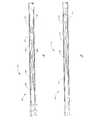
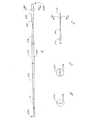
本発明のもう一つの実施形態では、バルーンカテーテル300は、特に、バルーンが取り付けられている領域において独自の可撓性を有する。図13Aに示すように、カテーテル300は、基端部314(図示せず)と先端部316を有する管状体312とその中を延在する内腔318とを備える。対応する膨張可能なバルーン322のような拡張可能な部材を管状体の先端部316に、好ましくは、バルーンの基端部322Aと先端部322Bをともに管状体312に取り付けて、設けている。芯線328は、管状体の先端部316の内腔318内に設けられており、そこから遠位の方向に延在している。コイル332が先端部316から延在し、芯線328を囲んでおり遠位のボール334まで続いている。
【0065】
管状体は、好ましくは、上記のようなニチノール材で成形する。管状体312の先端部分は、拡張可能な部材の拡張に呼応して軸方向に拡張するように構成されている。さらに詳しく説明すると、図13Aに示すバルーンカテーテルでは、管状体312の先端部分に、管状体の壁に設けた特殊な切込み352によってバルーン領域内に望ましい可撓性を付与している。これらの切込み352は、機械加工やEDMのような他の方法も可能であるが、好ましくはレーザを使って形成する。図13Aに示す好ましい実施形態では、管状体312の先端部分はコイル状になっている。しかし、内管は希望の可撓性を付与するため、さまざまな方法により、切込みを入れたり、形成することができる。
【0066】
図13Aに示す実施形態では、コイル状の内管の切込み352は、希望の可撓性により、好ましくは先端部316から1〜3mmのところで始まり、そこからバルーン322の長さまたはそれ以上近位の方向に延在する。例えば、約8mmの長さを有するバルーンの場合、切込みは、約2〜20mmの長さにわたり形成することができる。より高い可撓性が必要な実施形態では、内管の先端近くにのみ、短い範囲にわたり約2〜3mmの切込みを設ける。同様に、バルーンの基端部またはそれを越える範囲でさらに高い可撓性が望ましい場合には、切込みは、管状体に15mm以上の長さにわたって設けることもできる。
【0067】
内管コイルには、一定または可変幅および/またはピッチを設けて、カテーテルの可撓性を制御することができる。図13Aに示した実施形態では、管状体312を内管の先端部316から約2mmの位置から、バルーン322の基端部を超え、合計約15mmの長さに渡って切込みを入れる。切込み352の先端部では、管状体312内のコイルは、約0.15mmのリボン幅W1を有し、それが基端部に向けて徐々に広くなり、切込みの基端部では、約1から2mmのリボン幅となる。内管の長手の軸に対する切込み352の角度は、好ましくは、図13Aに示すように遠位の方向に向かって大きくなり、可撓性も先端部に向けて大きくなる。好ましい実施形態では、切込みの先端部で角度が約80であり、切込みの基端部で、約3と、徐々に小さくなっている。コイル状の部分全体にわたり、内管の切込みは、好ましくは約0.08mmのピッチとなっている。リボン幅が可変であることの利点は、管状体312と芯線328との間の可撓性を、より漸進的に移行させることができるという点である。さらに、切込みの角度を近位に向かって徐々に小さくすることにより、コイル状の管状体は、切込み角度の減少に伴って引っ張り強度が増す。
【0068】
コイル状の管状体の長さ、幅、ピッチ、角度のさらなる変化も考慮されることは理解できよう。例えば、図14に示すように、一定の幅でピッチW2が約0.25mmのコイルが使用される。さらに、コイル状の内管は、基端部で管状体の壁全体にわたらない程度の深さの切込みのコイルから始まり、内管が完全に貫通するまで遠位に向って徐々に深さを増すように形成する。この実施形態は、図15Aおよび15Bに示す。さらに、管状体312の先端部分には、特殊な熱処理を施してあり、可撓性を向上している。例えば、ある実施形態では、管状体312の先端約30mmは熱処理を施して可撓性を改善することができる。
【0069】
好ましい実施形態のカテーテル300を構成する際、管状体312を希望の形状に切った後、芯線328を準備して図13Aに示すように管状体312の先端部316内部に取り付ける。好ましい芯線328は、ニチノール材であり、基端部328A(図示せず)と先端部328Bを有する。図16A〜16Dに示すように、この芯線328は、好ましくは5つに区分される。基端部の第1区370は、実質的に一定の直径であり、第2区372はテーパ状であり、第3区374は、実質的に一定の直径であり、第4区376はテーパ状であり、第5区378は平坦な先端を有する。図16Aに示すように、好ましい実施形態では、第1区370は、直径約0.005〜0.006インチ、長さが約10mmであるのが好ましい。第2区372は、約6mmにわたってテーパ状になっており、約0.005〜0.006インチから約0.007インチに直径が増大している。第3区374は、実質的に一定の直径約0.007インチ、長さが約4mmである。第3区の先端が管状体312の先端部316と並ぶ。第4区376は、約13から15mmにわたってテーパ状であり、先端378が平坦になっており、長さが約10mm、厚みが約0.002インチである。区分378では、移行380部分でさらにテーパ状になっており、平坦な先端が厚みにおいて近位に向かって減っており、薄い平坦な区分378と丸いテーパ状の区分376との間の移行をさらに漸進的にしている。この移行380は、比較的平坦な表面と約3〜5mmの長さであるのが好ましい。
【0070】
さらに詳しくは、上記の本出願と同日提出の「カテーテルの芯線(CATHETER CORE WIRE)」[弁理士案件登録No.PERCUS.003CP1]と題した同時出願中の出願番号第09/253,971号に記載されている。カテーテル300には、長さと構造の異なる芯線も利用可能であることは理解できよう。よって、芯線は、基端側または先端側のテーパ部のうち一方だけを有するもの、複数の基端側および先端側テーパ部を有するもの、あるいはテーパ部を有さないものなどが可能である。さらに、芯線328は、第1区と第2区370,372を設けず、実質的にすべての芯線328が先端部316から外に延在するように構成することもできる。さらに、芯線は、先端のテーパ部に直接隣接して基端側テーパ部を有するものでもよい。
【0071】
好ましくは、コイル332は、芯線にはんだ付けされ、遠位に向かってテーパ状の部分376の始めから平坦な先端378の先端部まで延在する。よって、好ましい実施形態の芯線に関しては、コイル332は、約25mmの長さにわたり延在する。このコイル/芯線の半組立体を組み立てた後、管状体のまさに先端部316と一致する遠位のテーパ部分376の始点と、コイル332とが先端部316に当接するように、芯線328は、管状体312の内腔318に挿入される。芯線328は、中央の区分374の管状体312に好ましくは1箇所もしくは複数箇所、さらに好ましくは図13Aに示す点362,364において、クリンプ(crimp)によって取り付ける。管状体312の芯線328へのクリンプ(crimp)は、上記のように、圧力約120ksi、もしくはその他の圧力を使って行うことができる。クリンプ(crimp)に加え、あるいはクリンプ(crimp)の代わりに、芯線328をはんだ付け、接着剤、エポキシ、または当業者にとっては周知の他の方法により、管状体312に取り付けることができる。
【0072】
芯線328は、近位の方向に延在し、内管が切り込まれている領域を通って管状体312に入る。第1、第2、第3区370,372,374が管状体312内に延在する長さは、好ましくは約10〜100mmであり、さらに好ましくは約15〜60mmであり、図13Aおよび16Aに示した好ましい実施形態では、約20mmである。芯線328が内腔318から外側に延在する長さは、好ましくは約10〜200mm、さらに好ましくは、約15〜60mm、そして、図13Aでは約25mmである。芯線を近位の方向に内管の内部まで延在させることによって、芯線がカテーテルに対して付加的構造上の支持体として機能する。しかし、好ましい芯線は、近位の方向にテーパ状となっているため、芯線328は、管状体312の内壁に接触することはなく、よって、カテーテルが血管の曲がり部分を通過できる機能やバルーンの膨張はほとんどない。
【0073】
図13Aに示すように、バルーン322は、管状体の先端部に取り付けられ、バルーン322は、基端部322Aと先端部322Bとを有し、その両方とも管状体に取り付けられている。好ましい実施形態のバルーン322Aの長さは約8mmで、外径は約0.034インチであり、内径が約0.015インチである。図13Bの好ましい実施形態で示すように、バルーン322の動作領域の外側およびバルーンの近位の方向に延在するように切込み352を設ける。好ましくはスリーブ366を管状体312上に設け、バルーンの動作領域より近位に切込み352を設けることにより、内腔318から膨張流体が漏出しないように防ぐ。スリーブは、好ましくはPET,FEP,TFEまたは類似した材料から形成した収縮管を使用する。好ましい実施形態では、この収縮管は、約15mmの長さを有し、先端部316から約5mmから近位の方向に延在している。この収縮管により、切込みをバルーンの動作領域の近位に形成し、流体を逃がすことなく、可撓性を増すことができる。あるいは、図15Bに示すように、基端部の切込みが管状体の壁全体にわたって延在していない場合、または、バルーンの近位に切込みが設けられていない場合、収縮管は必要ない。
【0074】
バルーン322は、好ましくはC−Flex材または他の対応する材料から形成し、前述のように、接着剤または他の手段によって管状体312に接着する。接着剤ストッパ338および340を、前述のように、バルーンの両端から約2mmの位置に設け、接着剤336がバルーンの動作領域の中に入り込む長さを調整する。バルーンの膨張は、管状体312における切込みを介して行われる。
【0075】
図13Aに示す好ましい実施形態は、バルーン322の近位の管状体312に取り付けたコイル状のマーカ342も備える。マーカ342をコイル状にすることにより、先端部のバルーン部に可撓性を付与する。コイル342は、好ましくはプラチナもしくはそれに類似した材料から形成され、外径が約0.024インチ、内径が約0.016インチ、長さが約1mmである。図13Aに示すように、コイル状のマーカ342は、好ましくはバルーン322に当接する。マーカ342をコイル状として説明しているが、マーカは、切込みでもよく、あるいは、他の方法で形成され、可撓性を改善するものならよいことは理解できよう。
【0076】
接着テーパ344A,344Bおよび346がバルーンに隣接して設けられ、基端部322Aの管状体312とバルーン322との間、および先端部322Bのバルーン322と芯線328の間に移行領域を設けている。よって遠位のテーパ346は、バルーンの先端部から芯線328まで延在する。テーパ材は、前述のように、シアノアクリレート接着剤か、あるいは、UV硬化性またはその変形の接着剤のように、より柔軟な接着剤を使用するのが好ましい。図13Aに示した実施形態では、テーパ344Aは、好ましくはシアノアクリレート接着剤であり、接着剤344B、346は、好ましくはUV接着剤である。テーパ344Aの基端部と基端部322Aとの間の距離は、好ましくは約1〜3mmであり、さらに好ましくは約2.5mm未満であり、テーパ344A自体の長さは約1mm未満であるのが好ましい。しかし、前述の様に、テーパは一つだけでもよい。遠位のテーパ346の長さは、好ましくは約3mmである。他の詳細については、1998年2月19日提出の、「バルーンカテーテルおよびその製造方法(BALOON CATHETER AND METHOD OF MANUFACTURE)」と題した出願通し番号第09/026,225号と、1998年2月19日提出の、「医療用カテーテルの軸(SHAFT FOR MEDICAL CATHETHER)」と題した出願通し番号第09/026,105号に記載してあるため、ここでは反復する必要はないであろう。
【0077】
図13Aのバルーン322の膨張により、内管の中のコイルが長手方向に拡張し、バルーンの長手方向の拡張を調整する。この拡張は、バルーンに応力を均一に分散し、破裂性とバルーンの心合わせを向上させる。本発明者は、例えば、バルーンの拡張による内管の長手方向の伸びは一般的には約2〜4mmであるが、約10〜20mmであることを証明した。さらに、クリンプ(crimp)362、364の近位の芯線の区分370、372が管状体312の内壁に接触しないため、芯線328は、バルーンの長手方向の拡張を妨害することはない。
【0078】
本発明は、変形や修正が可能であることは一般の当業者によって明らかであろう。本発明の範囲は、図や前述の説明によって制限されるものではなく、添付の特許請求の範囲によってのみ制限される。
【図面の簡単な説明】
【図1】 本発明のバルーンカテーテルの側面図である。
【図2】 バルーンカテーテルの近位の部分に設けた膨張アダプタに機能的に連結したシリンジ組立体を表した図である。
【図3】 図2のカテーテル弁とバルーンカテーテルの斜視図であり、開放された膨張アダプタの内部に位置している様子を表した図である。
【図4】 図4Aおよび図4B。
それぞれ、ロープロファイルカテーテル弁の開放位置と閉鎖位置を表した図である。
【図5】 バルーンカテーテルの先端部の好ましい局面による断面図であり、特に、二本の接続ワイヤを介して管状体に取り付けた芯線を表す図である。
【図6】 図6A、図6B、および図6C。
図5に示すカテーテルの断面図であり、それぞれ6A−6A,6B−6B,6C−6Cに沿って切った部分を表す。
【図7】 バルーンカテーテルの先端部のもう一つの好ましい局面による断面図であり、特に、カテーテルの管状体内に位置する浮遊芯線を表す図である。
【図8】 図7に示したカテーテルのもう一つの実施形態を表す断面図である。
【図9】 図9Aおよび図9B。
その基端部をアダプタに取り付け、その先端部を膨張バルーンに取り付けた芯線を有するカテーテルの断面図である。
【図10】 図9Aのバルーンおよび芯線の断面図であり、バルーンが膨張して曲がっている状態を示すものである。
【図11】 図11Aおよび図11B。
図11Aは、その先端部に膨張していないバルーンを有し、その中に浮遊芯線を有するカテーテルの断面図である。
図11Bは、図11Aのカテーテルの断面図であり、バルーンを膨張した状態を表したものである。
【図12】 図12Aおよび図12B。
図12Aは、図11Aに示すカテーテルの基端部の拡大断面図である。
図12Bは、図12Aに示すカテーテルの基端部を線12B−12Bに沿って切った断面図である。
【図13】 図13Aおよび図13B。
図13Aは、長手方向に可撓性を有する内管を有するバルーンカテーテルの先端部の長手方向断面図である。
図13Bは、図13Aのバルーンの基端部の拡大図である。
【図14】 一定のリボン幅およびピッチを有するコイル状内管の側面図である。
【図15】 図15Aおよび図15B。
図15Aは、切り込み深さが可変の、長手方向に可撓性を有する内管を有するバルーンカテーテルの断面図である。
図15Bは、図15Aに示すバルーンの基端部の拡大図である。
【図16】 図16A、図16B、図16Cおよび図16D。
図13Aまたは図15Aの内管に挿入した芯線の側面図である。[0001]
(Technical field)
The present invention relates to a medical catheter for use in an intravascular procedure, and more particularly to a catheter with improved flexibility at its distal end.
(Background technology)
Medical catheters such as balloon catheters have proven effective in treating various vascular disorders. In addition, this type of catheter allows clinicians to treat disorders with minimal interventions that affect the complex and sometimes life-threatening surgery required in the past. be able to. For example, balloon angioplasty is a common procedure that relieves stenotic lesions in blood vessels (eg, clogged arteries) and reduces the need for cardiac bypass surgery.
[0002]
Since medical catheters must reach the intended treatment site through a tortuous vascular network, the catheter requires considerable flexibility, particularly at the tip. However, if the tip is too flexible, the clinician may bend itself when the catheter tip is advanced in the patient's body. One way to give the catheter the desired flexibility has been to incorporate a “core wire” at the distal end of the catheter. The core wire is a wire extending from the distal end portion of the catheter main body, and serves to support structurally in order to prevent escape, bending, twisting, and the like during advancement. Furthermore, the core wire is also flexible, and can be guided in a tortuous vascular network or other body cavity at the distal end of the catheter.
[0003]
However, the conventional core wire does not necessarily exhibit ideal flexibility with respect to the distal end portion of the catheter. For example, when the core wire is attached in the distal end portion of the catheter body, the catheter body has rigidity compared to the core wire having relatively flexibility, so that the flexibility suddenly shifts between the core wire and the catheter body. To do. This transition is undesirable because the catheter may refract sharply at the turn as it advances through the tortuous path. This makes it difficult to guide the catheter inside the blood vessel and increases the possibility of damaging the blood vessel.
[0004]
In addition, catheters with a balloon or other inflatable member at the tip have special problems with respect to device flexibility. For example, in many balloon catheters, the flexible transition between the position of the catheter balloon and the wire extending beyond the tip of the balloon may be too abrupt, in which case the catheter is intravascularly As the wire moves, the flexible wire can go through the bent part of the blood vessel, but the hard part where the balloon is located cannot go. As a result, the balloon may pierce the wall of the blood vessel while guiding the suddenly bent portion.
[0005]
These devices also have problems with respect to the size range of the balloon. When inflated, the balloon attached to the distal end of the catheter has a tendency to expand not only in the radial direction but also in the longitudinal direction. Depending on the balloon material used, the balloon length can range from minimal (eg, polyethylene terephthalate) to large (latex or C-flex). For example, in the case of a C flex balloon having a length of about 9 mm before being attached, when it is inflated, it becomes 2 to 20 mm longer in the entire length direction. Thus, if the catheter and / or core wire to which these balloons are attached is too stiff, the catheter and / or core wire may be bent or otherwise undesirably affected when the balloon is inflated.
[0006]
Furthermore, balloon alignment and rupture are also affected by the flexibility of the catheter. In particular, if balloon expansion is limited by catheter and / or core stiffness, the balloon will not expand uniformly. This results in non-uniform stress distribution within the balloon, and therefore insufficient alignment of the balloon. Furthermore, non-uniform stress distribution creates stress concentration points, reduces service life, and ultimately accelerates balloon failure.
[0007]
Thus, there is a need to improve the balloon catheter with the desired flexibility around and within the balloon to improve balloon coverage, alignment and rupture. There is also a need for improved catheter flexibility and improved transition between the proximal and distal ends of the catheter.
[0008]
(Disclosure of the Invention)
The present invention solves such deficiencies by providing a catheter with improved flexibility in and around the tip. Particularly in the case of a catheter with a balloon at its distal end, a preferred embodiment of the present invention improves the transition and flexibility of the catheter in and around the area where the balloon is attached. According to one aspect of the present invention, the catheter includes a longitudinal body having a proximal end and a distal end. At least one connection wire having a proximal end and a distal end is provided, the proximal end of the core wire is attached to the distal end of the long body, and the distal end of the core wire is the distal end of the long body. Extends beyond. The proximal end portion of the core wire is connected to the distal end of the connection wire and extends from the distal end toward the distal end. In some embodiments, since the core wire is not directly attached to the catheter body, a transition region is provided between the catheter body and the core wire so that the catheter gradually increases in flexibility.
[0009]
According to another aspect of the invention, a medical device includes a longitudinal body having a proximal end and a distal end. An expandable member is attached to the distal end of the longitudinal body. The core wire is along a longitudinal axis almost the same as the longitudinal main body, and has a proximal end portion and a distal end portion. The proximal end of the core wire is located within the expandable member and is spaced in a distal direction from the distal end of the elongated body. Means are also provided for connecting the longitudinal body to the core.
[0010]
According to another aspect of the present invention, a balloon catheter includes a long tubular body having a proximal end portion and a distal end portion, and a lumen extending through the inside thereof. An inflatable balloon is attached to the distal end of the tubular body. The core wire is substantially along the same longitudinal axis as the tubular body, and has a proximal end portion and a distal end portion. The proximal end of the core wire is spaced from the distal end of the tubular body to the outside of the lumen in a distal direction. A plurality of connecting wires connect the tip of the tubular body to the core wire.
[0011]
According to another aspect of the present invention, a catheter includes a long tubular body having a proximal end and a distal end, and a lumen extending through the inside thereof. A core wire having a proximal end portion and a distal end portion is provided, the proximal end portion of the core wire extends into the lumen of the tubular body, and the distal end portion extends in a distal direction from the tubular body. Yes. A part of the core wire is coaxially located inside the lumen, and an annular space is formed between the core wire and the tubular body. The annular space extends around the entire length of the portion located around the core wire and inside the lumen. The proximal end of the expandable member is mounted on the distal end of the tubular body, and the distal end is mounted on the core and distal from the tubular body.
[0012]
This embodiment can actually “float” the proximal end within the tubular body and move the core wire longitudinally within the tubular body when the catheter is advanced within the patient's vasculature. As the tip of the catheter bends, the core moves outwardly in a distal direction from the catheter to bend more gradually, so this longitudinal movement causes the catheter to move between the tubular body and the core. The effect of gradually increasing the flexibility is obtained. In addition, when a balloon or other expandable device is attached between the tubular body and the core, the longitudinal movement of the floating core is adapted to its longitudinal expansion by actuation of the balloon or expandable device. become able to.
[0013]
According to another aspect of the present invention, a catheter includes a long tubular body having a proximal end and a distal end, and a lumen extending through the inside thereof. A core wire having a proximal end portion and a distal end portion is provided, and the proximal end portion of the core wire extends to the distal end portion of the lumen, but is maintained in a state not attached to the lumen. A flexible member connects the tubular body to the core wire.
[0014]
According to another aspect of the present invention, a catheter includes a long tubular body having a proximal end and a distal end, and a lumen extending through the inside thereof. An expandable member is attached to the distal portion. The distal portion is configured to expand axially in response to expansion of the expandable member.
[0015]
According to another aspect of the present invention, a catheter includes a long tubular body having a proximal end and a distal end, and a lumen extending through the inside thereof. An expandable member is attached to the distal end of the tubular body. The tubular body has a coiled portion that extends at least partially within the expandable member to provide longitudinal flexibility to the tubular body when the expandable member is actuated. Yes.
[0016]
According to another aspect of the present invention, a catheter includes a long tubular body having a proximal end and a distal end, and a lumen extending through the inside thereof. The longitudinal body has a cut in the proximal portion of the at least partially expandable member.
[0017]
According to another aspect of the invention, the catheter includes a longitudinal assembly having a tip. A balloon is attached to a distal portion of the longitudinal assembly, the balloon comprising a sheet material attached to the longitudinal assembly, so that the sheet material located between the spaced locations inflates the balloon. In response to the expansion pressure of the gas, it is configured to expand outward. The longitudinal assembly is axially expandable between spaced positions to accommodate changes in the shape of the balloon as the balloon is inflated, thereby reducing stress in the balloon.
[0018]
According to another aspect of the present invention, a method of providing a catheter with a longitudinal assembly having a balloon is provided. The balloon is inflated in the body cavity. A portion of the longitudinal assembly extends axially longitudinally within the balloon during balloon inflation to reduce stress on the balloon material.
[0019]
(Best Mode for Carrying Out the Invention)
The preferred embodiment of the present invention represents a balloon catheter with improved flexibility, particularly in and around the balloon region. In the context of this document, these embodiments are described as being part of a single occlusion device having a single lumen, but the principles and aspects of these embodiments are not described herein. The present invention can also be applied to more complicated occlusion devices having structures and functions. For example, the inventors may use the embodiments described herein for an occlusion device that functions as a moorable guidewire or filter. Furthermore, the present embodiment can also be applied to a catheter having a balloon such as latex or silicone, or a catheter used for an expansion balloon made of a material such as polyethylene terephthalate. Furthermore, the present embodiment is applicable to a catheter that does not include a balloon such as an irrigation catheter used for drug delivery or radiation therapy, or a catheter that includes other types of expandable members such as filters and meshes. Is also applicable. The design of the catheter tip can also be applied to a normal guide wire. Thus, the guide wire may be hollow or solid. It will be apparent to those skilled in the art from the following description how to apply the embodiments described herein to various structures and functions.
[0020]
I. Overview of the occlusion device
A. Occlusion balloon guidewire
A preferred embodiment of the present invention relates to the use of an occlusion balloon / guidewire as shown schematically in FIG. These guidewires or catheters occlude blood vessels and allow slidable insertion or advancement of various other catheters and devices. The term “catheter” is here intended to include both guidewires and catheters having these desirable properties. The term “occlusion” refers to partial and total occlusion of a blood vessel.
[0021]
As shown in FIG. 1, the
[0022]
The length of the
[0023]
The
[0024]
[0025]
As shown in FIG. 1, an expandable member such as an
[0026]
B. Overview of balloon inflation / deflation
2-4 represent the inflation / deflation of the occlusion balloon guidewire catheter shown in FIG. As shown in FIG. 2, a
[0027]
The
[0028]
In particular, the
[0029]
This will be described with reference to FIGS.
[0030]
In the embodiment shown in FIGS. 4A and 4B, the low
[0031]
The
[0032]
Other inflation adapter / inflation syringe assemblies can also be used. For example, the
[0033]
II. Balloon catheter with connecting wire
FIG. 5 is a cross-sectional view of the distal end portion of the
[0034]
In particular, at the
[0035]
The connecting
[0036]
Furthermore, it is not necessary to use two wires to connect the tubular body to the core wire. Therefore, the core wire can be connected to the tip of the tubular body with only one wire, or can be connected with three or more wires. In addition, it is contemplated that different means may be used to connect the tubular body to the core, such as through only the
[0037]
As shown in FIGS. 5 and 6B, the two
[0038]
The
[0039]
As shown in FIGS. 5 and 6A-6C, a
[0040]
As shown in FIG. 5, the
[0041]
The
[0042]
The adhesive 136 applied to the proximal end and the
[0043]
A radiopaque marker or
[0044]
The
[0045]
The reduction in the diameter of the
[0046]
The
[0047]
By reducing the stress concentration point of the balloon, more uniform expansion is introduced, thus improving the alignment of the balloon. In particular, by mounting the balloon on the flexible member, the stress can be more evenly distributed within the balloon wall and the balloon can be expanded more uniformly. In addition, evenly expanding the balloon reduces the possibility of local weakening of the balloon, which can cause premature rupture or balloon failure.
[0048]
III. Coaxial core wire
7 and 8 illustrate another preferred embodiment of the tip of the
[0049]
More specifically, as shown in FIG. 7, the
[0050]
The
[0051]
[0052]
The
[0053]
As described in connection with FIGS. 5-6C above, optional
[0054]
The embodiment shown in FIG. 7 preferably includes a
[0055]
The flexibility and balloon characteristics of the catheter shown in FIG. 7 are improved by the fact that part of the core end is not glued or fixed to the
[0056]
FIG. 8 illustrates another embodiment of the
[0057]
As shown in FIG. 8, the
[0058]
Crimp 148 is preferably located about 1 mm from the distal end of
[0059]
The problem of bending due to balloon inflation will be described with reference to FIGS. 9A and 9B show a catheter 10 having a
[0060]
The problem with this shape is that the
[0061]
FIG. 11A shows another embodiment of a
[0062]
As shown in FIG. 12A, a
[0063]
As shown in FIG. 11B, when the
[0064]
IV. Inner tube having flexibility in the longitudinal direction
In another embodiment of the present invention, the
[0065]
The tubular body is preferably formed from a nitinol material as described above. The distal end portion of the
[0066]
In the embodiment shown in FIG. 13A, the coiled inner tube cut 352 preferably begins 1-3 mm from the
[0067]
The inner tube coil can be provided with a constant or variable width and / or pitch to control the flexibility of the catheter. In the embodiment shown in FIG. 13A, the
[0068]
It will be appreciated that further changes in the length, width, pitch and angle of the coiled tubular body are also considered. For example, as shown in FIG. 14, a coil having a constant width and a pitch W2 of about 0.25 mm is used. In addition, the coiled inner tube begins with a coil of depth of cut that does not extend across the entire wall of the tubular body at the proximal end and gradually increases in depth toward the distal end until the inner tube is fully penetrated. Form to increase. This embodiment is shown in FIGS. 15A and 15B. Furthermore, a special heat treatment is applied to the tip portion of the
[0069]
In constructing the
[0070]
For further details, see “CATHETER CORE WIRE” [patent attorney registration no. PERCUS. No. 09 / 253,971, co-pending application entitled “003CP1”. It will be appreciated that cores of different lengths and structures can be used for the
[0071]
Preferably, the
[0072]
The
[0073]
As shown in FIG. 13A, the
[0074]
The
[0075]
The preferred embodiment shown in FIG. 13A also includes a coiled
[0076]
Adhesive tapers 344A, 344B and 346 are provided adjacent to the balloon to provide transition regions between the
[0077]
Inflation of the
[0078]
It will be apparent to those skilled in the art that the present invention can be modified and modified. The scope of the invention is not limited by the figures and the foregoing description, but only by the appended claims.
[Brief description of the drawings]
FIG. 1 is a side view of a balloon catheter of the present invention.
FIG. 2 shows a syringe assembly operatively connected to an inflation adapter provided in the proximal portion of the balloon catheter.
3 is a perspective view of the catheter valve and balloon catheter of FIG. 2 and shows a state in which the catheter valve and the balloon catheter are positioned inside the opened expansion adapter. FIG.
FIG. 4A and FIG. 4B.
It is the figure showing the open position and closed position of a low profile catheter valve, respectively.
FIG. 5 is a cross-sectional view of the distal end portion of the balloon catheter according to a preferred aspect, and particularly shows a core wire attached to a tubular body via two connection wires.
6A, 6B, and 6C. FIG.
FIG. 6 is a cross-sectional view of the catheter shown in FIG. 5, showing parts cut along 6A-6A, 6B-6B, and 6C-6C, respectively.
FIG. 7 is a cross-sectional view according to another preferred aspect of the distal end of a balloon catheter, in particular a floating core located within the tubular body of the catheter.
8 is a cross-sectional view showing another embodiment of the catheter shown in FIG. 7. FIG.
9A and 9B.
It is sectional drawing of the catheter which has the core wire which attached the base end part to the adapter and attached the front-end | tip part to the inflation balloon.
FIG. 10 is a cross-sectional view of the balloon and the core wire of FIG. 9A, showing a state where the balloon is inflated and bent.
FIG. 11A and FIG. 11B.
FIG. 11A is a cross-sectional view of a catheter having a non-inflated balloon at its distal end and a floating core wire therein.
FIG. 11B is a cross-sectional view of the catheter of FIG. 11A and shows the balloon inflated.
FIG. 12A and FIG. 12B.
FIG. 12A is an enlarged cross-sectional view of the proximal end portion of the catheter shown in FIG. 11A.
12B is a cross-sectional view taken along line 12B-12B of the proximal end of the catheter shown in FIG. 12A.
FIG. 13A and FIG. 13B.
FIG. 13A is a longitudinal sectional view of a distal end portion of a balloon catheter having an inner tube having flexibility in the longitudinal direction.
FIG. 13B is an enlarged view of the proximal end portion of the balloon of FIG. 13A.
FIG. 14 is a side view of a coiled inner tube having a constant ribbon width and pitch.
FIG. 15A and FIG. 15B.
FIG. 15A is a cross-sectional view of a balloon catheter having a longitudinally flexible inner tube with variable depth of cut.
FIG. 15B is an enlarged view of the proximal end portion of the balloon shown in FIG. 15A.
16A, 16B, 16C and 16D. FIG.
It is a side view of the core wire inserted in the inner tube of FIG. 13A or FIG. 15A.
Claims (14)
Translated fromJapanese該先端部に連結される拡張可能部材であり、基端および先端を有する拡張可能部材とを備えるカテーテルであって、
該細長管状胴部は、その先端部のみにおいて切込みによって形成されたコイル状部を有し、該コイル状部は該拡張可能部材に近い基端に始まり、そこから連通し該拡張可能部材内部であって該拡張可能部材の基端と先端との間の端部に至り、
前記内孔は、前記拡張可能部材を膨張または収縮させるために、該拡張可能部材に流体を流し、
更に、前記コイル状部を部分的に覆い、該コイル状部の覆われた部分を経て前記内孔から流体が流れ出すのを防ぐスリーブを備え、該スリーブはコイル状部の基端近傍に基端を有するとともに、コイル状部の先端近傍に先端を有するカテーテル。An elongated tubular body having a base and a tip and having an inner bore extending therein;
An expandable member coupled to the distal end, the expandable member having a proximal end and a distal end,
The elongated tubular bodyhas a coiled portion formed by cutting only at its distal end, and the coiled portion starts from a proximal end close to the expandable member and communicates therewithin within the expandable member. To the end between the proximal and distal ends of the expandable member,
The inner bore allows fluid to flow through the expandable member to expand or contract the expandable member;
And a sleeve that partially covers the coil-shaped portion and prevents fluid from flowing out of the inner hole through the covered portion of the coil-shaped portion, the sleeve being proximal to the proximal end of the coil-shaped portion. And a catheter having a tip near the tip of the coiled portion.
該管状胴部に装着される基端および先端を有する膨張可能部材であって、該基端は該コイル状部の基端と先端との間にあって且つ該先端はコイル状部の先端に装着される膨張可能部材と、
該管状胴部を覆う管状体であって、該コイル状部の基端近傍であって該管状胴部の基端より遠位にある基端を有するとともに、該コイル状部の該先端近傍にある先端とを有する管状体とを備えるカテーテルであって、
該膨張可能部材は、流体が管状胴部の内孔を通り該管状胴部の先端側に位置し該管状体より遠位にあるコイル状部を経て、該管状胴部の内側から外側に向かいそして該膨張可能部材に流入することにより膨張するカテーテル。An elongate tubular body having a proximal end and a distal end and having an inner bore extending therein, the tubular body near the distal end being proximal to provide flexibility in the longitudinal direction to the tubular body. An elongated tubular body that is a coiled part having an end and a tip;
An inflatable member having a proximal end and a distal end attached to the tubular body, the proximal end being between the proximal end and the distal end of the coiled portion, and the distal end being attached to the distal end of the coiled portion An inflatable member,
A tubular body covering the tubular body, having a proximal end near the proximal end of the coiled portion and distal to the proximal end of the tubular body, and near the distal end of the coiled portion A catheter comprising a tubular body having a tip,
The inflatable member passesfrom the inside to the outside of the tubular body through a coiled portion located on the distal end side of the tubular body and distal to the tubular body through the inner hole of the tubular body.the catheter expands by flowing into said inflatable member.
Applications Claiming Priority (3)
| Application Number | Priority Date | Filing Date | Title |
|---|---|---|---|
| US09/253,591 | 1999-02-22 | ||
| US09/253,591US6500147B2 (en) | 1999-02-22 | 1999-02-22 | Flexible catheter |
| PCT/US2000/004367WO2000050113A2 (en) | 1999-02-22 | 2000-02-22 | Balloon catheter with axial flexibility |
Publications (2)
| Publication Number | Publication Date |
|---|---|
| JP2003520060A JP2003520060A (en) | 2003-07-02 |
| JP3704043B2true JP3704043B2 (en) | 2005-10-05 |
Family
ID=22960907
Family Applications (1)
| Application Number | Title | Priority Date | Filing Date |
|---|---|---|---|
| JP2000600723AExpired - LifetimeJP3704043B2 (en) | 1999-02-22 | 2000-02-22 | Balloon catheter with axial flexibility |
Country Status (7)
| Country | Link |
|---|---|
| US (2) | US6500147B2 (en) |
| EP (1) | EP1154817B1 (en) |
| JP (1) | JP3704043B2 (en) |
| AU (1) | AU3702400A (en) |
| CA (1) | CA2371893A1 (en) |
| DE (1) | DE60014857D1 (en) |
| WO (1) | WO2000050113A2 (en) |
Families Citing this family (138)
| Publication number | Priority date | Publication date | Assignee | Title |
|---|---|---|---|---|
| US6379334B1 (en)* | 1997-02-10 | 2002-04-30 | Essex Technology, Inc. | Rotate advance catheterization system |
| US6740104B1 (en)* | 1998-05-15 | 2004-05-25 | Advanced Cardiovascular Systems, Inc. | Enhanced catheter with alignment means |
| AU7720100A (en) | 1999-09-27 | 2001-04-30 | Essex Technology, Inc. | Rotate-to-advance catheterization system |
| US6443926B1 (en) | 2000-02-01 | 2002-09-03 | Harold D. Kletschka | Embolic protection device having expandable trap |
| US7322957B2 (en) | 2000-02-01 | 2008-01-29 | Harold D. Kletschka | Angioplasty device and method of making same |
| US6911036B2 (en)* | 2001-04-03 | 2005-06-28 | Medtronic Vascular, Inc. | Guidewire apparatus for temporary distal embolic protection |
| US20020161395A1 (en)* | 2001-04-03 | 2002-10-31 | Nareak Douk | Guide wire apparatus for prevention of distal atheroembolization |
| US20040236366A1 (en)* | 2002-05-16 | 2004-11-25 | Kennedy Kenneth C. | Non-buckling balloon catheter |
| US20030236495A1 (en)* | 2002-05-16 | 2003-12-25 | Kennedy Kenneth C. | Non-buckling balloon catheter |
| ATE376442T1 (en)* | 2002-08-06 | 2007-11-15 | Abbott Lab Vascular Entpr Ltd | BALLOON CATHETER WITH RADIO-OPAQUE MARKINGS |
| US20070167804A1 (en)* | 2002-09-18 | 2007-07-19 | Byong-Ho Park | Tubular compliant mechanisms for ultrasonic imaging systems and intravascular interventional devices |
| CA2499389A1 (en)* | 2002-09-18 | 2004-04-01 | The Board Of Trustees Of The Leland Stanford Junior University | Tubular compliant mechanisms for ultrasonic imaging systems and intravascular interventional devices |
| US7153277B2 (en)* | 2002-12-03 | 2006-12-26 | Scimed Life Systems, Inc. | Composite medical device with markers |
| US7331933B2 (en)* | 2002-12-31 | 2008-02-19 | Advanced Cardiovascular Systems, Inc. | Balloon catheter with a compression member for balloon bonding |
| DE50209306D1 (en) | 2002-12-31 | 2007-03-08 | Abbott Lab Vascular Entpr Ltd | Catheter with a more flexible area between stem and tip, and method of making the same |
| US7169118B2 (en)* | 2003-02-26 | 2007-01-30 | Scimed Life Systems, Inc. | Elongate medical device with distal cap |
| US7182735B2 (en)* | 2003-02-26 | 2007-02-27 | Scimed Life Systems, Inc. | Elongated intracorporal medical device |
| DE602004018908D1 (en)* | 2003-03-31 | 2009-02-26 | Memry Corp | MEDICAL DEVICES WITH MEDICAMENT ELUTION PROPERTIES AND METHOD OF PREPARATION THEREOF |
| US7473242B2 (en)* | 2003-04-30 | 2009-01-06 | Medtronic Vascular, Inc. | Method and systems for treating vulnerable plaque |
| US7303574B2 (en)* | 2003-08-07 | 2007-12-04 | Medtronic Vasculor, Inc. | Occlusion catheter with frictional valve |
| US7824392B2 (en) | 2003-08-20 | 2010-11-02 | Boston Scientific Scimed, Inc. | Catheter with thin-walled braid |
| US7615043B2 (en) | 2003-08-20 | 2009-11-10 | Boston Scientific Scimed, Inc. | Medical device incorporating a polymer blend |
| US8252014B2 (en) | 2004-03-03 | 2012-08-28 | Innovational Holdings Llc. | Rapid exchange balloon catheter with braided shaft |
| US7658723B2 (en)* | 2004-05-27 | 2010-02-09 | Abbott Laboratories | Catheter having plurality of stiffening members |
| US7794448B2 (en)* | 2004-05-27 | 2010-09-14 | Abbott Laboratories | Multiple lumen catheter and method of making same |
| US7625353B2 (en)* | 2004-05-27 | 2009-12-01 | Abbott Laboratories | Catheter having first and second guidewire tubes and overlapping stiffening members |
| US7785439B2 (en)* | 2004-09-29 | 2010-08-31 | Abbott Laboratories Vascular Enterprises Limited | Method for connecting a catheter balloon with a catheter shaft of a balloon catheter |
| US7815627B2 (en)* | 2004-05-27 | 2010-10-19 | Abbott Laboratories | Catheter having plurality of stiffening members |
| US7527606B2 (en)* | 2004-05-27 | 2009-05-05 | Abbott Laboratories | Catheter having main body portion with coil-defined guidewire passage |
| US7628769B2 (en)* | 2004-05-27 | 2009-12-08 | Abbott Laboratories | Catheter having overlapping stiffening members |
| US7785318B2 (en)* | 2004-05-27 | 2010-08-31 | Abbott Laboratories | Catheter having plurality of stiffening members |
| US9289576B2 (en)* | 2004-06-17 | 2016-03-22 | W. L. Gore & Associates, Inc. | Catheter assembly |
| US7166100B2 (en)* | 2004-06-29 | 2007-01-23 | Cordis Neurovascular, Inc. | Balloon catheter shaft design |
| US20060030835A1 (en)* | 2004-06-29 | 2006-02-09 | Sherman Darren R | Catheter shaft tubes and methods of making |
| US7542808B1 (en) | 2004-09-17 | 2009-06-02 | Cardiac Pacemakers, Inc. | Lead and catheter assembly |
| US8414527B2 (en) | 2004-09-21 | 2013-04-09 | Boston Scientific Scimed, Inc. | Rapid exchange catheters having a sealed guidewire lumen and methods of making the same |
| US8080030B2 (en)* | 2005-01-21 | 2011-12-20 | University Of South Florida | Endoscopic sheath having a biomimetic retractor |
| EP1861133B1 (en) | 2005-02-28 | 2012-11-21 | Spirus Medical Inc. | Rotate-to-advance catheterization system |
| US20060259066A1 (en)* | 2005-04-28 | 2006-11-16 | Euteneuer Charles L | Bifurcated artery filter system |
| US8317678B2 (en) | 2005-05-04 | 2012-11-27 | Olympus Endo Technology America Inc. | Rotate-to-advance catheterization system |
| US8343040B2 (en)* | 2005-05-04 | 2013-01-01 | Olympus Endo Technology America Inc. | Rotate-to-advance catheterization system |
| US8414477B2 (en)* | 2005-05-04 | 2013-04-09 | Olympus Endo Technology America Inc. | Rotate-to-advance catheterization system |
| EP2461180A1 (en) | 2005-05-04 | 2012-06-06 | Volcano Corporation | Miniature actuator mechanism for intravascular imaging |
| US8235942B2 (en)* | 2005-05-04 | 2012-08-07 | Olympus Endo Technology America Inc. | Rotate-to-advance catheterization system |
| US20090005645A1 (en)* | 2005-05-04 | 2009-01-01 | Frassica James J | Rotate-to- advance catheterization system |
| US7780650B2 (en) | 2005-05-04 | 2010-08-24 | Spirus Medical, Inc. | Rotate-to-advance catheterization system |
| US7780723B2 (en) | 2005-06-13 | 2010-08-24 | Edwards Lifesciences Corporation | Heart valve delivery system |
| US20070173862A1 (en)* | 2006-01-24 | 2007-07-26 | Jose Fernandez | Flexible support member with high pushability |
| DE202006002832U1 (en)* | 2006-02-22 | 2007-07-05 | Microcuff Gmbh | feeding tube |
| US8435229B2 (en) | 2006-02-28 | 2013-05-07 | Olympus Endo Technology America Inc. | Rotate-to-advance catheterization system |
| US8574220B2 (en) | 2006-02-28 | 2013-11-05 | Olympus Endo Technology America Inc. | Rotate-to-advance catheterization system |
| US8167929B2 (en) | 2006-03-09 | 2012-05-01 | Abbott Laboratories | System and method for delivering a stent to a bifurcated vessel |
| US20070260224A1 (en)* | 2006-03-09 | 2007-11-08 | Abbott Laboratories | Flexible catheter tip having a shaped head |
| US20080065013A1 (en)* | 2006-09-13 | 2008-03-13 | Boston Scientific Scimed, Inc. | Balloon catheter |
| CN101677797B (en)* | 2007-01-22 | 2013-04-24 | 泰勒医疗公司 | Catheter with guidewire lumen with tubular portion and sleeve |
| US20080306441A1 (en)* | 2007-04-10 | 2008-12-11 | Wilson-Cook Medical Inc. | Non-buckling balloon catheter with spring loaded floating flexible tip |
| JP2010524631A (en)* | 2007-04-23 | 2010-07-22 | インターヴェンショナル アンド サージカル イノヴェイションズ リミテッド ライアビリティ カンパニー | Guidewire with adjustable stiffness |
| US9387308B2 (en) | 2007-04-23 | 2016-07-12 | Cardioguidance Biomedical, Llc | Guidewire with adjustable stiffness |
| US8870755B2 (en) | 2007-05-18 | 2014-10-28 | Olympus Endo Technology America Inc. | Rotate-to-advance catheterization system |
| US20090005853A1 (en)* | 2007-06-26 | 2009-01-01 | Karim Osman | Integration Of Markers Into Bar Arms |
| US20090132019A1 (en)* | 2007-11-15 | 2009-05-21 | Medtronic Vascular, Inc. | Bifurcate Stent Delivery Catheter |
| JP2011512956A (en)* | 2008-02-26 | 2011-04-28 | ボストン サイエンティフィック サイムド,インコーポレイテッド | Balloon catheter with a highly durable tip |
| US8034099B2 (en) | 2008-03-27 | 2011-10-11 | Medtronic Vascular, Inc. | Stent prosthesis having select flared crowns |
| US9061119B2 (en) | 2008-05-09 | 2015-06-23 | Edwards Lifesciences Corporation | Low profile delivery system for transcatheter heart valve |
| US8652202B2 (en) | 2008-08-22 | 2014-02-18 | Edwards Lifesciences Corporation | Prosthetic heart valve and delivery apparatus |
| US20100087731A1 (en)* | 2008-10-07 | 2010-04-08 | Medtronic Vascular, Inc. | Method for Tracking Degradation of a Biodegradable Stent Having Superparamagnetic Iron Oxide Particles Embedded Therein |
| TW201039875A (en)* | 2009-03-31 | 2010-11-16 | Toray Industries | Guide wire and ablation catheter with balloon having the same |
| US9427302B2 (en)* | 2009-04-09 | 2016-08-30 | Medtronic Vascular, Inc. | Stent having a C-shaped body section for use in a bifurcation |
| US8052737B2 (en)* | 2009-05-05 | 2011-11-08 | Medtronic Vascular, Inc. | Implantable temporary flow restrictor device |
| US8506525B2 (en)* | 2009-11-12 | 2013-08-13 | University Of South Alabama | Wound sealing fluid delivery apparatus and method |
| US8241311B2 (en)* | 2009-12-15 | 2012-08-14 | Medtronic Vascular, Inc. | Methods and systems for bypassing an occlusion in a blood vessel |
| CA2789394C (en)* | 2010-02-09 | 2016-09-13 | Medinol Ltd. | Catheter tip assembled with a spring |
| US10342570B2 (en) | 2014-02-03 | 2019-07-09 | Medinol Ltd. | Device for traversing vessel occlusions and method of use |
| US20110230946A1 (en)* | 2010-03-16 | 2011-09-22 | Abbott Laboratories | Easy marker placement balloon mold |
| US9237961B2 (en) | 2010-04-23 | 2016-01-19 | Medtronic Vascular, Inc. | Stent delivery system for detecting wall apposition of the stent during deployment |
| US9402754B2 (en) | 2010-05-18 | 2016-08-02 | Abbott Cardiovascular Systems, Inc. | Expandable endoprostheses, systems, and methods for treating a bifurcated lumen |
| US9943668B2 (en)* | 2010-07-16 | 2018-04-17 | Sub3 Vascular, Llc | Guidewire and catheter system and method for treating a blood clot |
| JP5191615B2 (en)* | 2010-09-23 | 2013-05-08 | オリンパスメディカルシステムズ株式会社 | Bend catheter |
| WO2012109468A1 (en)* | 2011-02-09 | 2012-08-16 | Boston Scientific Scimed, Inc. | Balloon catheter |
| US9155619B2 (en) | 2011-02-25 | 2015-10-13 | Edwards Lifesciences Corporation | Prosthetic heart valve delivery apparatus |
| US8652098B2 (en)* | 2011-03-08 | 2014-02-18 | Abbott Cardiovascular Systems Inc. | Catheter with radiopaque coil |
| WO2012149205A1 (en) | 2011-04-27 | 2012-11-01 | Dolan Mark J | Nerve impingement systems including an intravascular prosthesis and an extravascular prosthesis and associated systems and methods |
| US20130046376A1 (en) | 2011-06-24 | 2013-02-21 | Ali Hassan | Method and devices for flow occlusion during device exchanges |
| US10434292B2 (en) | 2011-06-24 | 2019-10-08 | Access Closure | Method and devices for flow occlusion during device exchanges |
| WO2013016275A1 (en) | 2011-07-22 | 2013-01-31 | Cook Medical Technologies Llc | Irrigation devices adapted to be used with a light source for the identification and treatment of bodily passages |
| US9119716B2 (en)* | 2011-07-27 | 2015-09-01 | Edwards Lifesciences Corporation | Delivery systems for prosthetic heart valve |
| US8632467B2 (en) | 2011-10-12 | 2014-01-21 | Volcano Corporation | Rotational shape-memory actuators and associated devices, systems, and methods |
| JP6118335B2 (en) | 2011-12-09 | 2017-04-19 | ボストン サイエンティフィック サイムド,インコーポレイテッドBoston Scientific Scimed,Inc. | Recanalization catheter assembly |
| ES2696081T3 (en)* | 2012-04-23 | 2019-01-14 | Pq Bypass Inc | System for circumventing occlusions in a femoral artery |
| US9532785B2 (en) | 2012-05-09 | 2017-01-03 | Access Closure, Inc. | Method and devices for flow occlusion during device exchanges |
| US9144663B2 (en) | 2012-10-24 | 2015-09-29 | Medtronic, Inc. | Methods and devices for repairing and/or preventing paravalvular leakage post-implantation of a valve prosthesis |
| US8974482B2 (en) | 2012-12-21 | 2015-03-10 | Edgar Louis Shriver | Device to steer into subintimal false lumen and parallel park in true lumen |
| US9456897B2 (en) | 2013-02-21 | 2016-10-04 | Medtronic, Inc. | Transcatheter valve prosthesis and a concurrently delivered sealing component |
| US10569062B2 (en)* | 2013-09-09 | 2020-02-25 | Prytime Medical Devices, Inc. | Low profile occlusion catheter |
| US9789283B2 (en) | 2014-02-03 | 2017-10-17 | Medinol Ltd. | Catheter tip assembled with a spring |
| JP6442229B2 (en) | 2014-10-30 | 2018-12-19 | 株式会社グッドマン | Balloon catheter |
| WO2016071822A1 (en)* | 2014-11-03 | 2016-05-12 | Koninklijke Philips N.V. | Intravascular devices, systems, and methods having a radiopaque patterned flexible tip |
| US9974946B2 (en)* | 2015-04-07 | 2018-05-22 | NeuroTronik IP Holding (Jersey) Limited | Inflatable intravascular electrode supports for neuromodulation |
| CA2980018C (en) | 2015-03-19 | 2018-02-20 | Prytime Medical Devices, Inc. | System and method for low-profile occlusion balloon catheter |
| US10179046B2 (en) | 2015-08-14 | 2019-01-15 | Edwards Lifesciences Corporation | Gripping and pushing device for medical instrument |
| US10561496B2 (en) | 2015-09-16 | 2020-02-18 | Edwards Lifesciences Corporation | Perfusion balloon designs |
| US10350067B2 (en) | 2015-10-26 | 2019-07-16 | Edwards Lifesciences Corporation | Implant delivery capsule |
| US10321996B2 (en) | 2015-11-11 | 2019-06-18 | Edwards Lifesciences Corporation | Prosthetic valve delivery apparatus having clutch mechanism |
| US11219746B2 (en) | 2016-03-21 | 2022-01-11 | Edwards Lifesciences Corporation | Multi-direction steerable handles for steering catheters |
| US10799676B2 (en) | 2016-03-21 | 2020-10-13 | Edwards Lifesciences Corporation | Multi-direction steerable handles for steering catheters |
| US10799677B2 (en) | 2016-03-21 | 2020-10-13 | Edwards Lifesciences Corporation | Multi-direction steerable handles for steering catheters |
| US10368872B2 (en) | 2016-06-02 | 2019-08-06 | Prytime Medical Devices, Inc. | System and method for low profile occlusion balloon catheter |
| US10561510B2 (en) | 2016-06-10 | 2020-02-18 | Medtronic Vascular, Inc. | Customizing the elution profile of a stent |
| US10575946B2 (en) | 2016-09-01 | 2020-03-03 | Medtronic Vascular, Inc. | Heart valve prosthesis and separate support flange for attachment thereto |
| EP4327732A3 (en) | 2017-01-12 | 2024-04-24 | The Regents of The University of California | Endovascular perfusion augmentation for critical care |
| US20180228502A1 (en)* | 2017-02-13 | 2018-08-16 | Penumbra, Inc. | Dual lumen hypotube catheter |
| EP4613214A2 (en) | 2017-04-18 | 2025-09-10 | Edwards Lifesciences Corporation | Heart valve sealing devices and delivery devices therefor |
| US11224511B2 (en) | 2017-04-18 | 2022-01-18 | Edwards Lifesciences Corporation | Heart valve sealing devices and delivery devices therefor |
| CA3060519A1 (en) | 2017-04-21 | 2018-10-25 | The Regents Of The University Of California | Aortic flow meter and pump for partial-aortic occlusion |
| US10973634B2 (en) | 2017-04-26 | 2021-04-13 | Edwards Lifesciences Corporation | Delivery apparatus for a prosthetic heart valve |
| US10959846B2 (en) | 2017-05-10 | 2021-03-30 | Edwards Lifesciences Corporation | Mitral valve spacer device |
| EP4397285A3 (en) | 2017-06-30 | 2024-09-25 | Edwards Lifesciences Corporation | Lock and release mechanisms for trans-catheter implantable devices |
| CN116196149A (en) | 2017-06-30 | 2023-06-02 | 爱德华兹生命科学公司 | Transcatheter valve docking station |
| US10857334B2 (en) | 2017-07-12 | 2020-12-08 | Edwards Lifesciences Corporation | Reduced operation force inflator |
| US10806573B2 (en) | 2017-08-22 | 2020-10-20 | Edwards Lifesciences Corporation | Gear drive mechanism for heart valve delivery apparatus |
| US11051939B2 (en) | 2017-08-31 | 2021-07-06 | Edwards Lifesciences Corporation | Active introducer sheath system |
| IL316784A (en) | 2017-10-18 | 2025-01-01 | Edwards Lifesciences Corp | Catheter assembly |
| US11207499B2 (en) | 2017-10-20 | 2021-12-28 | Edwards Lifesciences Corporation | Steerable catheter |
| PT3787561T (en) | 2018-04-30 | 2022-05-27 | Edwards Lifesciences Corp | DEVICES FOR CRIMPING PROSTHETIC IMPLANTS |
| CN116269937A (en) | 2018-04-30 | 2023-06-23 | 爱德华兹生命科学公司 | Push-on sheath style |
| US11844914B2 (en) | 2018-06-05 | 2023-12-19 | Edwards Lifesciences Corporation | Removable volume indicator for syringe |
| DE102018114583A1 (en)* | 2018-06-18 | 2019-12-19 | Nemos Gmbh | Arrangement for transmitting torsional moments, in particular as a torsion spring or drive shaft made of fiber composite materials in order to achieve a high specific material utilization |
| EP3833273A4 (en) | 2018-08-06 | 2022-06-29 | Prytime Medical Devices, Inc. | System and method for low profile occlusion balloon catheter |
| US11779728B2 (en) | 2018-11-01 | 2023-10-10 | Edwards Lifesciences Corporation | Introducer sheath with expandable introducer |
| JP7502298B2 (en) | 2018-12-11 | 2024-06-18 | エドワーズ ライフサイエンシーズ コーポレイション | Delivery system for prosthetic heart valves - Patents.com |
| WO2020123281A1 (en) | 2018-12-12 | 2020-06-18 | Edwards Lifesciences Corporation | Combined introducer and expandable sheath |
| SG11202107448UA (en) | 2019-01-16 | 2021-08-30 | Edwards Lifesciences Corp | Apparatus and method for monitoring valve expansion |
| EP4121159A2 (en) | 2020-03-16 | 2023-01-25 | Certus Critical Care, Inc. | Blood flow control devices, systems, and methods and error detection thereof |
| EP4487822A3 (en) | 2020-08-24 | 2025-04-09 | Edwards Lifesciences Corporation | Commissure marker for a prosthetic heart valve |
| PL4203851T3 (en) | 2020-08-31 | 2025-06-23 | Edwards Lifesciences Corporation | Systems and methods for crimping and device preparation |
| WO2022197895A1 (en) | 2021-03-18 | 2022-09-22 | Prytime Medical Devices, Inc. | Vascular occlusion catheter |
| USD1084324S1 (en) | 2023-08-01 | 2025-07-15 | Edwards Lifesciences Corporation | Handle for implant delivery device |
| WO2025070550A1 (en)* | 2023-09-27 | 2025-04-03 | Sbカワスミ株式会社 | Balloon-equipped guide wire, catheter set, and medical instrument |
Family Cites Families (37)
| Publication number | Priority date | Publication date | Assignee | Title |
|---|---|---|---|---|
| US3467101A (en) | 1965-09-30 | 1969-09-16 | Edwards Lab Inc | Balloon catheter |
| US4276874A (en)* | 1978-11-15 | 1981-07-07 | Datascope Corp. | Elongatable balloon catheter |
| US4351341A (en)* | 1980-08-15 | 1982-09-28 | Uresil Company | Balloon catheter |
| US4944727A (en)* | 1986-06-05 | 1990-07-31 | Catheter Research, Inc. | Variable shape guide apparatus |
| US5449343A (en) | 1985-07-30 | 1995-09-12 | Advanced Cardiovascular Systems, Inc. | Steerable dilatation catheter |
| US4723936A (en) | 1986-07-22 | 1988-02-09 | Versaflex Delivery Systems Inc. | Steerable catheter |
| US4715378A (en) | 1986-07-28 | 1987-12-29 | Mansfield Scientific, Inc. | Balloon catheter |
| USRE34633E (en) | 1987-11-13 | 1994-06-07 | Cook Incorporated | Balloon guide |
| US4848344A (en) | 1987-11-13 | 1989-07-18 | Cook, Inc. | Balloon guide |
| US4943278A (en)* | 1988-02-29 | 1990-07-24 | Scimed Life Systems, Inc. | Dilatation balloon catheter |
| US4998917A (en)* | 1988-05-26 | 1991-03-12 | Advanced Cardiovascular Systems, Inc. | High torque steerable dilatation catheter |
| US6027863A (en) | 1991-09-05 | 2000-02-22 | Intratherapeutics, Inc. | Method for manufacturing a tubular medical device |
| US5605162A (en) | 1991-10-15 | 1997-02-25 | Advanced Cardiovascular Systems, Inc. | Method for using a variable stiffness guidewire |
| US5324259A (en) | 1991-12-18 | 1994-06-28 | Advanced Cardiovascular Systems, Inc. | Intravascular catheter with means to seal guidewire port |
| US5243996A (en) | 1992-01-03 | 1993-09-14 | Cook, Incorporated | Small-diameter superelastic wire guide |
| JP3345147B2 (en) | 1993-01-26 | 2002-11-18 | テルモ株式会社 | Vasodilators and catheters |
| US5344402A (en) | 1993-06-30 | 1994-09-06 | Cardiovascular Dynamics, Inc. | Low profile perfusion catheter |
| CA2102250A1 (en) | 1993-11-02 | 1995-05-03 | Robert S. Schwartz | Flexible catheter guidewire |
| US5456665C1 (en) | 1994-03-04 | 2001-05-22 | Arrow Internat Invest Corp | Intra-aortic balloon catheter |
| EP0749333A1 (en) | 1994-03-10 | 1996-12-27 | Schneider (Usa) Inc. | Catheter having shaft of varying stiffness |
| US5507765A (en)* | 1994-04-28 | 1996-04-16 | Mott; James B. | Punch-type surgical instrument for skin incision, set of parts for making such an instrument of selectably variable size, and blade unit for such instrument |
| JP3970341B2 (en) | 1994-06-20 | 2007-09-05 | テルモ株式会社 | Vascular catheter |
| US5454795A (en) | 1994-06-27 | 1995-10-03 | Target Therapeutics, Inc. | Kink-free spiral-wound catheter |
| US5779688A (en) | 1994-10-28 | 1998-07-14 | Intella Interventional Systems, Inc. | Low profile balloon-on-a-wire catheter with shapeable and/or deflectable tip and method |
| US5599326A (en)* | 1994-12-20 | 1997-02-04 | Target Therapeutics, Inc. | Catheter with multi-layer section |
| JPH09639A (en) | 1995-06-23 | 1997-01-07 | New Ueebu Medical:Kk | Coronary vein expander for ptca surgery |
| JP3432060B2 (en)* | 1995-09-05 | 2003-07-28 | テルモ株式会社 | Vasodilator |
| US5746701A (en) | 1995-09-14 | 1998-05-05 | Medtronic, Inc. | Guidewire with non-tapered tip |
| US6004279A (en) | 1996-01-16 | 1999-12-21 | Boston Scientific Corporation | Medical guidewire |
| US6068623A (en) | 1997-03-06 | 2000-05-30 | Percusurge, Inc. | Hollow medical wires and methods of constructing same |
| US6050972A (en) | 1996-05-20 | 2000-04-18 | Percusurge, Inc. | Guidewire inflation system |
| US6544276B1 (en) | 1996-05-20 | 2003-04-08 | Medtronic Ave. Inc. | Exchange method for emboli containment |
| US5993424A (en) | 1996-08-05 | 1999-11-30 | Cordis Corporation | Guidewire having a distal tip that can change its shape within a vessel |
| US6554795B2 (en) | 1997-03-06 | 2003-04-29 | Medtronic Ave, Inc. | Balloon catheter and method of manufacture |
| US5814064A (en)* | 1997-03-06 | 1998-09-29 | Scimed Life Systems, Inc. | Distal protection device |
| US6066149A (en)* | 1997-09-30 | 2000-05-23 | Target Therapeutics, Inc. | Mechanical clot treatment device with distal filter |
| US6228072B1 (en) | 1998-02-19 | 2001-05-08 | Percusurge, Inc. | Shaft for medical catheters |
- 1999
- 1999-02-22USUS09/253,591patent/US6500147B2/ennot_activeExpired - Lifetime
- 2000
- 2000-02-22AUAU37024/00Apatent/AU3702400A/ennot_activeAbandoned
- 2000-02-22CACA002371893Apatent/CA2371893A1/ennot_activeAbandoned
- 2000-02-22WOPCT/US2000/004367patent/WO2000050113A2/enactiveIP Right Grant
- 2000-02-22DEDE2000614857patent/DE60014857D1/ennot_activeExpired - Lifetime
- 2000-02-22JPJP2000600723Apatent/JP3704043B2/ennot_activeExpired - Lifetime
- 2000-02-22EPEP00915811Apatent/EP1154817B1/ennot_activeExpired - Lifetime
- 2002
- 2002-10-21USUS10/277,719patent/US20030060802A1/ennot_activeAbandoned
Also Published As
| Publication number | Publication date |
|---|---|
| EP1154817B1 (en) | 2004-10-13 |
| CA2371893A1 (en) | 2000-08-31 |
| AU3702400A (en) | 2000-09-14 |
| US6500147B2 (en) | 2002-12-31 |
| WO2000050113A2 (en) | 2000-08-31 |
| US20020007146A1 (en) | 2002-01-17 |
| DE60014857D1 (en) | 2004-11-18 |
| US20030060802A1 (en) | 2003-03-27 |
| JP2003520060A (en) | 2003-07-02 |
| WO2000050113A3 (en) | 2000-12-07 |
| EP1154817A2 (en) | 2001-11-21 |
Similar Documents
| Publication | Publication Date | Title |
|---|---|---|
| JP3704043B2 (en) | Balloon catheter with axial flexibility | |
| EP3359239B1 (en) | Occlusion bypassing apparatus with a re-entry needle and a distal stabilization balloon | |
| EP1023100B1 (en) | Method of manufacture of a balloon catheter | |
| EP1212116B1 (en) | Expandable micro-catheter | |
| AU2001271320B2 (en) | Balloon occlusion device having a proximal valve | |
| JP4680907B2 (en) | Devices and methods across chronic total occlusion | |
| EP0843571B1 (en) | Vascular dilatation device | |
| US5843050A (en) | Microcatheter | |
| JP5453299B2 (en) | Drug delivery catheter having an inflatable communication portion between two axially spaced balloons | |
| US8628519B2 (en) | Rapid exchange bias laser catheter design | |
| US6319229B1 (en) | Balloon catheter and method of manufacture | |
| JP2004503339A (en) | Medical equipment | |
| EP0254701A1 (en) | Steerable catheter | |
| US20040073162A1 (en) | Balloon construction for occlusion device | |
| JP2004510524A (en) | Method and apparatus for protecting a proximal end of a medical device | |
| JP2008546431A (en) | Heart valve delivery system | |
| JP3533299B2 (en) | Nickel-titanium slip medical catheter wire | |
| JP5234548B2 (en) | catheter | |
| US6786888B1 (en) | Low profile catheter for emboli protection | |
| EP2196174B1 (en) | Process for loading a stent onto a stent delivery system | |
| US20240198039A1 (en) | Catheters with laser cut hypotube scaffold for flow under significant pressure differentials | |
| WO2024103030A1 (en) | Micro balloon catheter with distal vent |
Legal Events
| Date | Code | Title | Description |
|---|---|---|---|
| A977 | Report on retrieval | Free format text:JAPANESE INTERMEDIATE CODE: A971007 Effective date:20041224 | |
| A131 | Notification of reasons for refusal | Free format text:JAPANESE INTERMEDIATE CODE: A131 Effective date:20050111 | |
| A521 | Request for written amendment filed | Free format text:JAPANESE INTERMEDIATE CODE: A523 Effective date:20050411 | |
| TRDD | Decision of grant or rejection written | ||
| A01 | Written decision to grant a patent or to grant a registration (utility model) | Free format text:JAPANESE INTERMEDIATE CODE: A01 Effective date:20050621 | |
| A61 | First payment of annual fees (during grant procedure) | Free format text:JAPANESE INTERMEDIATE CODE: A61 Effective date:20050721 | |
| R150 | Certificate of patent or registration of utility model | Ref document number:3704043 Country of ref document:JP Free format text:JAPANESE INTERMEDIATE CODE: R150 Free format text:JAPANESE INTERMEDIATE CODE: R150 | |
| FPAY | Renewal fee payment (event date is renewal date of database) | Free format text:PAYMENT UNTIL: 20080729 Year of fee payment:3 | |
| S531 | Written request for registration of change of domicile | Free format text:JAPANESE INTERMEDIATE CODE: R313531 | |
| FPAY | Renewal fee payment (event date is renewal date of database) | Free format text:PAYMENT UNTIL: 20080729 Year of fee payment:3 | |
| R360 | Written notification for declining of transfer of rights | Free format text:JAPANESE INTERMEDIATE CODE: R360 | |
| FPAY | Renewal fee payment (event date is renewal date of database) | Free format text:PAYMENT UNTIL: 20080729 Year of fee payment:3 | |
| R350 | Written notification of registration of transfer | Free format text:JAPANESE INTERMEDIATE CODE: R350 | |
| FPAY | Renewal fee payment (event date is renewal date of database) | Free format text:PAYMENT UNTIL: 20090729 Year of fee payment:4 | |
| R250 | Receipt of annual fees | Free format text:JAPANESE INTERMEDIATE CODE: R250 | |
| FPAY | Renewal fee payment (event date is renewal date of database) | Free format text:PAYMENT UNTIL: 20100729 Year of fee payment:5 | |
| R250 | Receipt of annual fees | Free format text:JAPANESE INTERMEDIATE CODE: R250 | |
| FPAY | Renewal fee payment (event date is renewal date of database) | Free format text:PAYMENT UNTIL: 20110729 Year of fee payment:6 | |
| R250 | Receipt of annual fees | Free format text:JAPANESE INTERMEDIATE CODE: R250 | |
| FPAY | Renewal fee payment (event date is renewal date of database) | Free format text:PAYMENT UNTIL: 20120729 Year of fee payment:7 | |
| R250 | Receipt of annual fees | Free format text:JAPANESE INTERMEDIATE CODE: R250 | |
| FPAY | Renewal fee payment (event date is renewal date of database) | Free format text:PAYMENT UNTIL: 20120729 Year of fee payment:7 | |
| FPAY | Renewal fee payment (event date is renewal date of database) | Free format text:PAYMENT UNTIL: 20130729 Year of fee payment:8 | |
| R250 | Receipt of annual fees | Free format text:JAPANESE INTERMEDIATE CODE: R250 | |
| R250 | Receipt of annual fees | Free format text:JAPANESE INTERMEDIATE CODE: R250 | |
| R250 | Receipt of annual fees | Free format text:JAPANESE INTERMEDIATE CODE: R250 | |
| R250 | Receipt of annual fees | Free format text:JAPANESE INTERMEDIATE CODE: R250 | |
| R250 | Receipt of annual fees | Free format text:JAPANESE INTERMEDIATE CODE: R250 | |
| R250 | Receipt of annual fees | Free format text:JAPANESE INTERMEDIATE CODE: R250 | |
| R250 | Receipt of annual fees | Free format text:JAPANESE INTERMEDIATE CODE: R250 | |
| R250 | Receipt of annual fees | Free format text:JAPANESE INTERMEDIATE CODE: R250 | |
| EXPY | Cancellation because of completion of term |