JP3703627B2 - Gas sensor - Google Patents
Gas sensorDownload PDFInfo
- Publication number
- JP3703627B2 JP3703627B2JP17143898AJP17143898AJP3703627B2JP 3703627 B2JP3703627 B2JP 3703627B2JP 17143898 AJP17143898 AJP 17143898AJP 17143898 AJP17143898 AJP 17143898AJP 3703627 B2JP3703627 B2JP 3703627B2
- Authority
- JP
- Japan
- Prior art keywords
- cylinder member
- caulking
- filter
- hardness
- outer cylinder
- Prior art date
- Legal status (The legal status is an assumption and is not a legal conclusion. Google has not performed a legal analysis and makes no representation as to the accuracy of the status listed.)
- Expired - Lifetime
Links
- 238000001514detection methodMethods0.000claimsdescription43
- 229910001220stainless steelInorganic materials0.000claimsdescription15
- 239000010935stainless steelSubstances0.000claimsdescription11
- 235000019589hardnessNutrition0.000description80
- 239000007789gasSubstances0.000description65
- 239000001301oxygenSubstances0.000description53
- 229910052760oxygenInorganic materials0.000description53
- QVGXLLKOCUKJST-UHFFFAOYSA-Natomic oxygenChemical compound[O]QVGXLLKOCUKJST-UHFFFAOYSA-N0.000description51
- 238000010438heat treatmentMethods0.000description29
- 238000002788crimpingMethods0.000description25
- 229910052751metalInorganic materials0.000description22
- 239000002184metalSubstances0.000description22
- 239000000919ceramicSubstances0.000description17
- 230000002093peripheral effectEffects0.000description14
- 230000035939shockEffects0.000description11
- 238000000137annealingMethods0.000description10
- 238000000034methodMethods0.000description10
- 238000012360testing methodMethods0.000description10
- WABPQHHGFIMREM-UHFFFAOYSA-Nlead(0)Chemical compound[Pb]WABPQHHGFIMREM-UHFFFAOYSA-N0.000description9
- 230000001012protectorEffects0.000description9
- XLYOFNOQVPJJNP-UHFFFAOYSA-NwaterSubstancesOXLYOFNOQVPJJNP-UHFFFAOYSA-N0.000description9
- 229910000831SteelInorganic materials0.000description8
- 230000000694effectsEffects0.000description8
- 238000011156evaluationMethods0.000description8
- 230000008569processEffects0.000description8
- 230000001681protective effectEffects0.000description8
- 239000010959steelSubstances0.000description8
- 230000008859changeEffects0.000description7
- 229920001343polytetrafluoroethylenePolymers0.000description7
- 239000004810polytetrafluoroethyleneSubstances0.000description7
- 238000010586diagramMethods0.000description6
- 229910000963austenitic stainless steelInorganic materials0.000description5
- 230000008878couplingEffects0.000description5
- 238000010168coupling processMethods0.000description5
- 238000005859coupling reactionMethods0.000description5
- 238000003780insertionMethods0.000description5
- 230000037431insertionEffects0.000description5
- 239000000463materialSubstances0.000description5
- 238000012545processingMethods0.000description5
- 239000007784solid electrolyteSubstances0.000description5
- 238000005482strain hardeningMethods0.000description5
- 229920000544Gore-TexPolymers0.000description4
- 238000007667floatingMethods0.000description4
- 239000007788liquidSubstances0.000description4
- 238000012423maintenanceMethods0.000description4
- 230000009471actionEffects0.000description3
- 230000000903blocking effectEffects0.000description3
- 230000006835compressionEffects0.000description3
- 238000007906compressionMethods0.000description3
- 230000007547defectEffects0.000description3
- 238000002474experimental methodMethods0.000description3
- 230000001771impaired effectEffects0.000description3
- 239000000203mixtureSubstances0.000description3
- -1polytetrafluoroethylenePolymers0.000description3
- 230000002265preventionEffects0.000description3
- XEEYBQQBJWHFJM-UHFFFAOYSA-NIronChemical compound[Fe]XEEYBQQBJWHFJM-UHFFFAOYSA-N0.000description2
- 238000013459approachMethods0.000description2
- 239000012298atmosphereSubstances0.000description2
- 230000003197catalytic effectEffects0.000description2
- 238000004891communicationMethods0.000description2
- 238000001816coolingMethods0.000description2
- 230000007423decreaseEffects0.000description2
- 238000010494dissociation reactionMethods0.000description2
- 238000005242forgingMethods0.000description2
- 239000012212insulatorSubstances0.000description2
- 238000005304joiningMethods0.000description2
- 230000014759maintenance of locationEffects0.000description2
- 238000004519manufacturing processMethods0.000description2
- 229910000734martensiteInorganic materials0.000description2
- 238000002844meltingMethods0.000description2
- 230000008018meltingEffects0.000description2
- 230000008646thermal stressEffects0.000description2
- RYGMFSIKBFXOCR-UHFFFAOYSA-NCopperChemical compound[Cu]RYGMFSIKBFXOCR-UHFFFAOYSA-N0.000description1
- 101000920618Homo sapiens Transcription and mRNA export factor ENY2Proteins0.000description1
- 101150000971SUS3 geneProteins0.000description1
- 101150065537SUS4 geneProteins0.000description1
- 102100031954Transcription and mRNA export factor ENY2Human genes0.000description1
- GEIAQOFPUVMAGM-UHFFFAOYSA-NZrOInorganic materials[Zr]=OGEIAQOFPUVMAGM-UHFFFAOYSA-N0.000description1
- 230000004913activationEffects0.000description1
- 229910000287alkaline earth metal oxideInorganic materials0.000description1
- 150000001342alkaline earth metalsChemical class0.000description1
- 229910052782aluminiumInorganic materials0.000description1
- XAGFODPZIPBFFR-UHFFFAOYSA-NaluminiumChemical compound[Al]XAGFODPZIPBFFR-UHFFFAOYSA-N0.000description1
- PNEYBMLMFCGWSK-UHFFFAOYSA-Naluminium oxideInorganic materials[O-2].[O-2].[O-2].[Al+3].[Al+3]PNEYBMLMFCGWSK-UHFFFAOYSA-N0.000description1
- 238000005452bendingMethods0.000description1
- 230000015572biosynthetic processEffects0.000description1
- 238000006243chemical reactionMethods0.000description1
- 239000013065commercial productSubstances0.000description1
- 150000001875compoundsChemical class0.000description1
- 238000012790confirmationMethods0.000description1
- 229910052802copperInorganic materials0.000description1
- 239000010949copperSubstances0.000description1
- 230000007797corrosionEffects0.000description1
- 238000005260corrosionMethods0.000description1
- 238000005336crackingMethods0.000description1
- 125000004122cyclic groupChemical class0.000description1
- 230000005593dissociationsEffects0.000description1
- 208000018459dissociative diseaseDiseases0.000description1
- 239000000835fiberSubstances0.000description1
- 230000006872improvementEffects0.000description1
- 229910052742ironInorganic materials0.000description1
- 229910001105martensitic stainless steelInorganic materials0.000description1
- 230000007246mechanismEffects0.000description1
- 238000012986modificationMethods0.000description1
- 230000004048modificationEffects0.000description1
- 239000012299nitrogen atmosphereSubstances0.000description1
- 150000002926oxygenChemical class0.000description1
- 239000012466permeateSubstances0.000description1
- 239000000843powderSubstances0.000description1
- 239000002244precipitateSubstances0.000description1
- 238000001556precipitationMethods0.000description1
- 239000000047productSubstances0.000description1
- 229910001404rare earth metal oxideInorganic materials0.000description1
- 238000005215recombinationMethods0.000description1
- 230000006798recombinationEffects0.000description1
- 239000005871repellentSubstances0.000description1
- 239000011347resinSubstances0.000description1
- 229920005989resinPolymers0.000description1
- 230000002441reversible effectEffects0.000description1
- 239000006104solid solutionSubstances0.000description1
- 239000000454talcSubstances0.000description1
- 229910052623talcInorganic materials0.000description1
- 238000010998test methodMethods0.000description1
- 230000037303wrinklesEffects0.000description1
- 229910000859α-FeInorganic materials0.000description1
Images


Classifications
- G—PHYSICS
- G01—MEASURING; TESTING
- G01N—INVESTIGATING OR ANALYSING MATERIALS BY DETERMINING THEIR CHEMICAL OR PHYSICAL PROPERTIES
- G01N27/00—Investigating or analysing materials by the use of electric, electrochemical, or magnetic means
- G01N27/26—Investigating or analysing materials by the use of electric, electrochemical, or magnetic means by investigating electrochemical variables; by using electrolysis or electrophoresis
- G01N27/403—Cells and electrode assemblies
- G01N27/406—Cells and probes with solid electrolytes
- G01N27/407—Cells and probes with solid electrolytes for investigating or analysing gases
Landscapes
- Chemical & Material Sciences (AREA)
- Life Sciences & Earth Sciences (AREA)
- Health & Medical Sciences (AREA)
- Physics & Mathematics (AREA)
- Chemical Kinetics & Catalysis (AREA)
- Electrochemistry (AREA)
- Molecular Biology (AREA)
- Analytical Chemistry (AREA)
- Biochemistry (AREA)
- General Health & Medical Sciences (AREA)
- General Physics & Mathematics (AREA)
- Immunology (AREA)
- Pathology (AREA)
- Measuring Oxygen Concentration In Cells (AREA)
Description
Translated fromJapanese【0001】
【発明の属する技術分野】
本発明は、酸素センサ、HCセンサ、NOXセンサなど、測定対象となるガス中の被検出成分を検出するためのガスセンサに関する。
【0002】
【従来の技術】
従来より、上述のようなガスセンサとして、被検出成分を検出する検出部が先端に形成された棒状ないし筒状の検出素子を、金属製のケーシングの内側に配置した構造のものが知られている。この金属製のケーシングは、外周面にセンサ取付け用のねじ部が形成された主体金具、その主体金具の一端側から突出する検出素子の検出部を覆う形で主体金具に結合されるプロテクタ、そのプロテクタとは反対側から主体金具に結合されるとともに、主体金具の後方に延びる検出素子を覆う内筒部材、さらには、その内筒部材の後端部に結合され、検出素子からのリード線を後方側の開口部から延出させる外筒部材など、複数の筒状体を組み合わせて構成される。
【0003】
このうち、内筒部材と外筒部材とは例えばステンレス鋼にて形成されるが、多くのセンサにおいて、これらは次のような加締め接合により結合されていることが多い。すなわち、外筒部材の端部を内筒部材の対応する端部に外側から重ね合わせて重なり部を形成し、その重なり部において外筒部材を内筒部材に向けて周方向に加締めることにより環状の加締め部を形成して、両者を気密に結合した状態とする。
【0004】
ところで、上記のような内筒部材と外筒部材とを加締め接合するに際しては、加締めに先立って両部材の硬度調整を行うことが、がたつきやゆるみが生じにくく気密性に優れた接合状態を得る上で重要である。例えば、特開平9−210953号公報には、酸素センサの内筒部材と外筒部材とをステンレス鋼で構成した場合、内筒部材(内側カバー)のビッカース硬度をHv150〜350、外筒部材(外側カバー)のビッカース硬度をHv100〜300に調整することにより、耐震性とシール性に優れた加締め接合状態が得られる旨が記載されている。また、その実施形態例には、具体的な数値として外筒部材の硬度をHv150(ただし厚さ0.5mm)、内筒部材の硬度をHv240(ただし厚さ0.7mm)とする例が挙げられている。
【0005】
【発明が解決しようとする課題】
ところで、ガスセンサ、例えば酸素センサは、高温の排気ガスが流通する排気管やエキゾーストマニホルドに取り付けて使用されることが多い関係上、センサ温度は、不使用時には室温前後となる一方、高速高負荷運転時には数百℃にも昇温するため、かなり激しい熱衝撃が繰返し付加されることとなる。しかしながら、上記公報においては、加締め接合状態に及ぼす振動付加と被水(あるいは冠水)の影響については論じられているが、上記のような熱衝撃付加の影響については詳しい言及がほとんどなされていない。そして、本発明者らが鋭意検討した結果、外筒部材及び内筒部材の硬度値として上記公報に記載された値を採用した場合、センサの加締め接合部は、厳しい熱履歴を付加した後においては、加締め接合部が必ずしも良好な気密性を維持し得ないことが判明したのである。
【0006】
本発明の課題は、検出素子を覆う内筒部材と外筒部材とが加締め接合された構成を有し、かつ熱衝撃等が加わりやすい使用環境下においても、その加締め部が良好な気密性を維持しうるガスセンサを提供することにある。
【0007】
【課題を解決するための手段及び作用・効果】
上記課題を解決するために本発明のガスセンサは、
先端部に検出部が形成された棒状ないし筒状形態をなし、測定対象となるガス(被測定ガス)中の被検出成分を検出する検出素子と、
検出部への被測定ガスの流通を許容した状態で、検出素子の外側を覆う筒状のケーシングとを備え、
そのケーシングは、軸線方向に隣接配置される2つの筒状部を少なくとも含んで構成され、それら2つの筒状部は、対応する端部において一方のもの(以下、内筒部材という)が他方のもの(以下、外筒部材という)の内側に位置する形で重なり部を生ずるように配置されており、
内筒部材のビッカース硬度H1がHv250〜430、外筒部材のビッカース硬度H2がHv160〜330、両者の硬度差H1−H2が30以上とされ、重なり部においてそれら内筒部材と外筒部材とが、周方向に形成された加締め部により気密状態で接合されていることを特徴とする。
【0008】
上記本発明のガスセンサの構成によれば、内筒部材と外筒部材との硬度を上記のように設定することにより、熱衝撃等の加わりやすい使用環境下においても、加締め部が良好な気密性を維持しうるものとなる。
【0009】
本発明の構成において重要な点は、まず、外筒部材のビッカース硬度H2をHv160以上と、例えば前記公報に開示された値よりも高めに設定したことにある。すなわち、外筒部材のビッカース硬度を高めることにより加締め部の硬度が高められるので、熱サイクル付加時に加締め部に生ずる熱応力変形が抑制されて緩み等が生じにくくなり、気密性が向上するものと考えられる。そして、内筒部材のビッカース硬度H1をHv250以上とさらに高い値に設定し、加えて外筒部材との硬度差H1−H2が30以上となるように設定することで、上記のように硬度の高い外筒部材を加締めた場合に、内筒部材はその加締め力を十分に受けとめることができるようになり、密着力の高い加締め部形成が可能となる。
【0010】
外筒部材のビッカース硬度H2がHv160未満になると、加締め部の耐熱衝撃性が低下し、繰返し熱サイクルが加わった場合に十分な気密性が確保できなくなる。また、内筒部材との間の硬度差H1−H2が30未満になると、内筒部材が加締め力を十分に受けとめられなくなって望まざる強変形を起こし、また、外筒部材の加締め変形も不十分となって、得られる加締め部の気密性が損なわれる不具合につながる。なお、内筒部材のビッカース硬度H1がHv250未満になるか、あるいは外筒部材のビッカース硬度H2がHv330を超えると、加締め部の耐熱衝撃性が低下し、繰返し熱サイクルが加わった場合に十分な気密性が確保できなくなる。その理由は、まず、内筒部材のビッカース硬度H1がHv250未満になった場合は、該内筒部材の剛性の絶対値が不足する結果、加締め時に望まざる強変形を起こして気密性が損なわれるものと考えられる。他方、外筒部材のビッカース硬度H2がHv330を超えた場合は、外筒部材の剛性が高くなり過ぎ、加締め時の変形が不十分になるか、あるいは無理に加締めようとしたときに不均一変形や割れ等を生じやすくなって、同様に気密性が損なわれるものと考えられる。なお、上記硬度差H1−H2はより望ましくは50以上とするのがよい。
【0011】
次に、内筒部材の肉厚は0.6〜1.0mmとするのがよく、外筒部材の肉厚は0.2〜0.6mmとするのがよい。内筒部材の肉厚が0.6mm未満になると、その硬度H1をHv250以上に確保していても加締め力の受け止めが不十分となり、加締め部の気密性が損なわれる場合がある。また、内筒部材の肉厚が1.0mmを超えると、加締め加工が困難となる場合がある。他方、外筒部材の肉厚が0.2mm未満になると該部材の強度不足による変形等が生じやすくなる。また、外筒部材の肉厚が0.6mmを超えると、加締め力が内筒部材に作用しにくくなり、健全な加締め部を得にくくなる場合がある。
【0012】
また、本発明者らの検討によれば、内筒部材との間で30以上(望ましくは50以上)の硬度差が生じている限り、外筒部材の硬度H2として少なくともHv160が確保されていることで、内筒部材の硬度H1がHv430までは、そのレベルによらず、加締め部の耐熱衝撃性を良好に確保できることが判明している。このことは、内筒部材の硬度レベルが高くなるほど、良好な加締め部が得られる外筒部材の硬度範囲が拡がること、換言すれば、工程上の要因で外筒部材の硬度が多少ばらついた場合でも、耐熱衝撃性に優れた良好な加締め部が得やすくなることを意味している。具体的には、内筒部材の硬度H1をHv300以上とすることで、良好な加締め部を形成できる外筒部材の硬度範囲が顕著に拡がり、工程管理も容易となる。この観点において、内筒部材の硬度H1は、より望ましくはHv330以上に設定するのがよい。なお、内筒部材あるいは外筒部材の材質として、例えばオーステナイト鋼などの冷間加工可能な鉄系材料を例示することができるが、この場合、その硬度レベルは一般にはHv430以下の範囲のものとなる。
【0013】
他方、外筒部材が、例えばオーステナイト系ステンレス鋼の鍛造、引抜あるいは深絞り工等の冷間加工により製造されたものである場合、そのビッカース硬度H2は、より望ましくはHv175〜275の範囲で調整するのがよい。これは、以下の理由による。
【0014】
すなわち、冷間加工後の部材は加工硬化の進行により、Hv350〜400前後と加締め加工には不向きな高硬度状態になっていることが多いので、部材を加締め加工するのに先立って加工に適した硬度範囲のものとなるよう、これを適当な温度で焼鈍(焼なまし)することが望ましい。この場合、冷間加工材の焼鈍後の硬度は焼鈍温度に対して必ずしも直線的に変化せず、温度の上昇に対してある温度までは硬度の変化は比較的小さいが(第一温度域)、その温度に到達すると比較的狭い特定の温度域にて硬度が急激に減少し(第二温度域)、それよりも高温側では再び温度上昇に対する硬度変化が鈍くなる(第三温度域)という挙動をとる。
【0015】
そして、外筒部材のビッカース硬度H2を上記範囲に設定することで、硬度変化の比較的小さい第三温度域、あるいは第二温度域高温側における焼鈍処理により部材の硬度調整を行うことが可能となり、焼鈍温度が多少ずれても加締め加工に適した硬度レベルを安定して得ることが可能となる。なお、内筒部材は、加工後に特に焼鈍を施さなくとも、その硬度をHv250〜430の範囲内のものにできる場合がある。また、外筒部材についても温間加工などの採用により、加工後の焼鈍を省略しても、その硬度をHv160〜330の範囲内のものにできる場合がある。
【0016】
内筒部材あるいは外筒部材の具体的な材質としては、耐食性確保の観点から前述のようにステンレス鋼を使用することが望ましい。具体的には、JIS:G4304に記載された各種ステンレス鋼があり、例えば、SUS201、SUS202、SUS301、SUS301J、SUS302、SUS302B、SUS304、SUS304L、SUS304N1、SUS304N2、SUS304LN、SUS305、SUS309S、SUS310S、SUS316、SUS316L、SUS316N、SUS316LN、SUS316J1、SUS316J1L、SUS317、SUS317L、SUS317J1、SUS321、SUS347、SUSXM15J1等のオーステナイト系ステンレス鋼(常温においてもオーステナイト組織を示すステンレス鋼)、SUS329J1、SUS329J2L等のオーステナイト−フェライト系ステンレス鋼(オーステナイトとフェライトの2相組織を示すステンレス鋼)、SUS405、SUS410L、SUS429、SUS430、SUS430LX、SUS434、SUS436L、SUS444、SUS447J1、SUSXM27等のフェライト系ステンレス鋼(熱処理によって硬化せず、かつフェライト組織を示すステンレス鋼)、SUS631等の析出硬化系ステンレス鋼(アルミニウム、銅などの元素を添加することにより、熱処理によってこれらの元素を主体とする化合物等を析出させ、硬化させることができるステンレス鋼)等を例示できる。
【0017】
また、本発明でいう「ステンレス鋼」の概念には、下記に例示される耐熱鋼も含まれるものとする。
▲1▼オーステナイト系耐熱鋼
例えばJIS:G4311及びG4312に組成が規定されたものがあり、SUS31、SUH35、SUH36、SUH37、SUH38、SUH309、SUH310、SUH330、SUH660、SUH661等を例示できる。なお、該オーステナイト系耐熱鋼は、本発明においてオーステナイト系ステンレス鋼の概念に含まれるものとする。
▲2▼フェライト系耐熱鋼
例えばJIS:G4311及びG4312に組成が規定されたものがあり、SUH446等を例示できる。なお、該フェライト系耐熱鋼は、本発明においてフェライト系ステンレス鋼の概念に含まれるものとする。
▲3▼マルテンサイト系耐熱鋼
例えばJIS:G4311及びG4312に組成が規定されたものがあり、SUS1、SUS3、SUS4、SUS11、SUS600、SUS616等を例示できる。なお、該マルテンサイト系耐熱鋼は、本発明においてマルテンサイト系ステンレス鋼の概念に含まれるものとする。
【0018】
これらのうち、加工(特に冷間加工)の容易性ひいては部材の製造能率向上の観点から、フェライト系ステンレス鋼及びオーステナイト系ステンレス鋼を本発明に好適に使用でき、高温多湿となるセンサの使用環境を考慮すれば、オーステナイト系ステンレス鋼を使用することが特に望ましいといえる。
【0019】
なお、内筒部材と外筒部材との重なり部には、該外筒部材を前記内筒部材に向けて加締めることにより、それらの周方向に円環状に形成された主加締め部と、該円環状の主加締め部において外筒部材と内筒部材とが、それらの軸線周りにおいて相対的に回転することを阻止する回転阻止部とを形成することができる。この構成によれば、主加締め部においては、内筒部材と外筒部材との間の接触面が円筒状面となるので気密性に優れ、それらの間から内筒部材内に水等が漏れ込むことが確実に阻止される。また、該主加締め部と共に回転阻止部を形成することで、内筒部材と外筒部材との間に軸線回りの捩じり力が作用しても、両者の間に相対的な回転が生じにくく、ひいては上記主加締め部における気密性を一層確実なものとすることができる。
【0020】
回転阻止部は、外筒部材の軸線方向において主加締め部の少なくとも一方の側に、該外筒部材を内筒部材に向けて加締めることにより形成された補助加締め部とすれば、その形成も容易で回転阻止効果にも優れる。補助加締め部は、具体的には、外筒部材の軸線方向において主加締め部に対し所定の間隔で隣接し、かつ該外筒部材の周方向に沿う環状に形成することができる。環状形態の補助加締め部を主加締め部に隣接して形成することで、回転阻止効果が一層高められる。この場合、さらに具体的には、補助加締め部の軸断面形状を多角形状とすることができる。こうすれば、内筒部材と外筒部材との接触面が角筒状となり、捩じり力が作用した場合の内筒部材と外筒部材との間の相対的な回転が極めて生じにくくなる。
【0021】
なお、補助加締め部は、主加締め部よりも検出素子に近い側に形成するのがよい。すなわち、センサの先端側は高温にさらされることが多いので、気密性確保が優先される主加締め部がそのような熱源から遠くなる上記配置関係がより望ましいといえる。
【0022】
また、主加締め部と補助加締め部とは、それぞれ外筒部材を周方向外側から圧縮する複数の加締めパンチを含むとともに、外筒部材の軸線方向において所定距離だけ隔たった位置関係で配置される2組の加締めパンチユニットを用いて一括して形成することができる。この方式によれば、主加締め部と補助加締め部とが1回の加締め工程により同時形成されるので能率的であるばかりでなく、次のような効果も合わせて達成される。すなわち、加締めパンチによる圧縮により、外筒部材が内筒部材に向けて局所的に食い込みつつ圧接されて加締め部が形成されるのであるが、その圧接部の周囲において外筒部材には、食込変形に伴うしわ寄せ部あるいは浮き上がり部が形成されやすい。ここで、主加締め部と補助加締め部とを順次的に形成した場合、後で形成する加締め部によるしわ寄せ部あるいは浮き上がり部の影響が先に形成した加締め部に及び、気密性が損なわれる問題が生じやすい。しかしながら、上述のように両加締め部を同時に形成するようにすれば、しわ寄せ部あるいは浮き上がり部の影響をそれら加締め部の間の領域にプールすることができ、ひいてはいずれの加締め部においても十分な密着性すなわち気密性を確保することができるようになる。
【0023】
なお、上記ガスセンサの構成においては検出素子を、その検出部が、ケーシング内に導入される外気を基準ガスとして作動する酸素濃淡電池素子を含むものとして構成することができる。この場合、内筒部材を検出素子を収容する主筒とし、外筒部材をその主筒とは独立した筒状体としてこれにほぼ同軸的に設けられ、検出素子からのリード線が自身の後方外側へ延びることを許容しつつ、主筒に対し後方側から連結されるフィルタアセンブリとすることができる。そして、そのフィルタアセンブリは、主筒に対し後方側からほぼ同軸的に連結される筒状形態をなすとともに内部が該主筒の内部と連通し、かつ壁部に1ないし複数の気体導入孔が形成されたフィルタ保持部と、該フィルタ保持部の気体導入孔を塞ぐように配置され、液体の透過は阻止し気体の透過は許容するフィルタとを備えて構成することができる。この場合、それらフィルタ及び気体導入孔を経て外気が主筒内に導入されることとなる。なお、本明細書においては、酸素検出素子の軸方向においてその先端部に向かう側を「前方側」、これと反対方向に向かう側を「後方側」とする。
【0024】
上記構成の特徴の要旨は、フィルタを含む気通構造部をフィルタアセンブリとして主筒とは独立に構成し、これを主筒に連結・一体化した構成を有する点にある。これにより、次のような効果が達成される。
▲1▼フィルタアセンブリの組立ては、酸素検出素子などの主筒内への組付けとは独立に行うことができるので、例えば検出素子のリード線が邪魔になったりせず、組立作業を極めて能率的に行うことができる。
▲2▼主筒内への部品の組付けと、フィルタアセンブリの組立てとを並行して行えるので、生産性が飛躍的に向上する。また、フィルタの組付け不良などが生じても、フィルタアセンブリの段階で不良が発見できれば、センサ完成品に該不良の影響は及ばず、部品等の無駄等が生じにくい。
【0025】
なお、本発明においてフィルタは、例えばポリテトラフルオロエチレン等、フッ素系樹脂からなる多孔質樹脂形成物で構成された防水性かつ通気性を有するものを使用できる。具体的には、例えばポリテトラフルオロエチレン(以下、PTFEという)の未焼成成形体を、PTFEの融点よりも低い加熱温度で1軸以上の方向に延伸することにより得られる多孔質繊維構造体(例えば、特公昭42−13560、特公昭51−18991、特公昭56−45773、特公昭56−17216、特開昭145735、特開昭59−152825、特開平3−221541、特開平7−126428、特開平7−196831等、商品名:例えばゴアテックス(ジャパンゴアテックス(株)))を用いたものを使用できる。
【0026】
フィルタアセンブリは、主筒の後方側に対し内部が互いに連通するようにこれと同軸的かつ一体的に設けられ、壁部に1ないし複数の気体導入孔が形成されたフィルタ保持部と、該フィルタ保持部の外側において気体導入孔を塞ぐように配置され、液体の透過は阻止し気体の透過は許容するフィルタと、そのフィルタの外側に配置される筒状に形成され、壁部に1ないし複数の補助気体導入孔が形成されるとともに、該フィルタをフィルタ保持部との間で挟み付けて保持する補助フィルタ保持部とを備えたものとして構成できる。この場合、補助気体導入孔からフィルタを経て気体導入孔より外気が主筒内に導入される。すなわち、内外のフィルタ保持部によりフィルタを確実に保持することができ、フィルタ保持部へのフィルタの組付けも容易である。例えばフィルタを円筒状に形成した場合、フィルタ保持部に対し該フィルタを外挿し、さらにその外側から補助フィルタ保持部を嵌め入れ、気体導入孔及び補助気体導入孔と干渉しない位置において、フィルタ保持部と補助フィルタ保持部とを結合する保持部結合部を形成すればよい。
【0027】
気体導入孔及び補助気体導入孔は、それぞれフィルタ保持部及び補助フィルタ保持部に対し、軸方向中間部において互いに対応する位置関係で周方向に沿って所定の間隔で複数個形成することができる。これにより、フィルタアセンブリ側から主筒内へ外気を偏りなく導入することができる。また、フィルタ保持部を周方向に取り囲むように、例えば筒状のフィルタをその外側に配置し、補助フィルタ保持部には保持部結合部として、フィルタを挟んで該補助フィルタ保持部をフィルタ保持部に向けて加締めることにより、その周方向に沿って環状のフィルタ加締め部を形成することができる。保持部結合部を環状のフィルタ加締め部とすることで、フィルタアセンブリの組立てが一層容易となる。なお、この環状の加締め部は、軸方向において気体導入孔及び補助気体導入孔の列を挟む両側に形成できる。この場合、各加締め部において、補助フィルタ保持部とフィルタ保持部との間にフィルタの縁を挟み込む形にすることで、補助気体導入孔からフィルタの縁を迂回してフィルタ保持部の気体導入孔ヘ至る経路が形成されにくくなり、ここを通って水等がフィルタ保持部内側ひいては主筒内側へ漏れ込む可能性も小さくなる。
【0028】
また、フィルタを上述のように筒状に形成してフィルタ保持部の外周に沿うように配置する場合、補助フィルタ保持部は、その軸方向後端縁がフィルタの後端縁に対応して位置するように配置でき、該後端縁に沿って周方向にフィルタ加締め部を形成することができる。これにより、補助フィルタ保持部の後端面位置において、フィルタ保持部との間に位置するフィルタを目視できるようになる。このようにすれば、次のような利点がある。すなわち、フィルタ保持部に筒状のフィルタを外挿し、その状態でさらに補助フィルタ保持部をフィルタ保持部に対して軸方向に相対移動させながら嵌め入れる際に、フィルタが補助フィルタ保持部と連れ移動して位置ずれを起こすことがありうる。この場合、万一この状態でフィルタ加締め部が形成されれば、加締め部からフィルタが外れてシールが不完全となるのであるが、フィルタの後端面部分が上述のように目視できるようになっていることで、そのようなフィルタの加締め不良を容易に発見できる。
【0029】
また、補助フィルタ保持部の前端縁側にフィルタ加締め部を形成する場合、そのフィルタ加締め部においてフィルタを部分的に露出させるフィルタ確認露出部を形成することもできる。こうすれば、補助フィルタ保持部の前端縁側においても加締め部においてフィルタが正常に加締められているか否かを容易に判別できる。
【0030】
【発明の実施の形態】
以下、本発明の実施の形態を図面に示す実施例に基づき説明する。
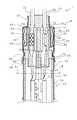
図1は本発明のガスセンサの一実施例たる酸素センサの内部構造を示している。該酸素センサ1は、先端が閉じた中空軸状の固体電解質部材である酸素検出素子2と、軸状のセラミックヒータである発熱体3とを備えて構成される。酸素検出素子2は酸素イオン伝導性を有する固体電解質により構成されている。そのような固体電解質としては、Y2O3ないしCaOを固溶させたZrO2が代表的なものであるが、それ以外のアルカリ土類金属ないし希土類金属の酸化物とZrO2との固溶体を使用してもよい。また、ベースとなるZrO2にはHfO2が含有されていてもよい。
【0031】
この酸素検出素子2の中間部外側には、絶縁性セラミックから形成されたインシュレータ6,7、並びにタルクから形成されたセラミック粉末8を介して金属製のケーシング10が設けられ、酸素検出素子2はケーシング10と電気的に絶縁された状態で貫通している。ケーシング10は、酸素センサ1を排気管等の取付部に取り付けるためのねじ部9bを有する主体金具9、その主体金具9の一方の開口部に内側が連通するように結合された内筒部材としての主筒14、該主筒14とは反対側から主体金具9に取り付けられたプロテクタ100等を備える。また、図2に示すように、酸素検出素子2の内面及び外面には、そのほぼ全面を覆うように一対の電極層2b,2cが設けられている。これら電極層2b,2cはいずれも、酸素検出素子2を構成する固体電解質へ酸素を注入するための酸素分子の解離反応、及び該固体電解質から酸素を放出させるための酸素の再結合反応に対する可逆的な触媒機能(酸素解離触媒機能)を有する多孔質電極、例えばPt多孔質電極として構成されている。
【0032】
なお、以下においては、酸素検出素子2の軸方向においてその閉じた先端部に向かう側を「前方側(あるいは先端側)」、これと反対方向に向かう側を「後方側(あるいは後端側)」として説明を行う。
【0033】
まず、主体金具9の前方側開口部には筒状のプロテクタ装着部9aが形成され、ここに、酸素検出素子2の先端側(検出部)を所定の空間を隔てて覆うようにキャップ状のプロテクタ100が装着されている。プロテクタ100には、排気ガスを透過させる複数のガス透過口103〜106が貫通形態で形成されている。これにより排気ガス中の酸素が酸素検出素子2の先端側表面に接触可能となっている。
【0034】
次に、主体金具9の後方側の開口部には、前述の主筒14がインシュレータ6との間にリング15を介して加締められ、この主筒14にさらに外筒部材としてのフィルタアセンブリ16が外側から嵌合・固定されている。このフィルタアセンブリ16の図中上端側の開口はゴム等で構成されたグロメット(弾性シール部材)17で封止され、またこれに続いてさらに内方にセラミックセパレータ18が設けられている。そして、それらセラミックセパレータ18及びグロメット17を貫通するように、酸素検出素子2用のリード線20,21及び発熱体3用のリード線(リード線20,21の影になって見えない)が配置されている。
【0035】
次に、図3に示すように、セラミックセパレータ18には、各リード線20,21を挿通するための複数のセパレータ側リード線挿通孔72が軸方向に貫通して形成されており、その軸方向中間位置には、外周面から突出する形態でフランジ状のセパレータ側支持部73が形成されている。そして、該セラミックセパレータ18は、セパレータ側支持部73よりも前方側に位置する部分を主筒14の後端部内側に入り込ませた状態で、該セパレータ側支持部73において主筒14の後端面に当接するとともに、セパレータ側支持部73よりも後方側に位置する部分を主筒14の外側に突出させた状態で配置される。
【0036】
酸素検出素子2用の一方のリード線20は、端子金具23のコネクタ部24及びこれに続く引出し線部25、並びに端子金具23の内部電極接続部26を経て、前述の酸素検出素子2の内側の電極層2c(図2)と電気的に接続されている。一方、他方のリード線21は、別の端子金具33のコネクタ部34及びこれに続く引出し線部35並びに外部電極接続部35bを経て、酸素検出素子2の外側の電極層2b(図2)と電気的に接続されている。
【0037】
ここで、酸素検出素子2は、排気ガス温が十分高温となっている場合には当該排気ガスで加熱されて活性化されるが、エンジン始動時など排気ガス温が低温である場合には前述の発熱体3で強制的に加熱することで活性化される。発熱体3は、通常はセラミックヒータであり、例えばアルミナを主とするセラミック棒45の先端部に、例えば蛇行状に形成された抵抗発熱線部(図示せず)を有する発熱部42が設けられたものである。この抵抗発熱線部は、ヒータ端子部40から延びるリード線を経て通電されることにより、酸素検出素子2の先端部(検出部)を所定の活性化温度以上に加熱する役割を果たす。
【0038】
また、上述の発熱体3は、端子金具23により酸素検出素子2の中空部内に保持される。この端子金具23には、前述の内部電極接続部26に関して発熱体3の先端側(すなわち発熱部42に近い側)に発熱体把持部27が形成されている。発熱体把持部27は、発熱体3の周囲を包囲するC字状の横断面形状を有している。そして、発熱体3を未挿入の状態では該発熱体3の外径よりは少し小さい内径を有し、発熱体3の挿入に伴い弾性的に拡径してその摩擦力により該発熱体3を把持する。図1の構成において、この発熱体把持部27は内部電極接続部26の片側の1箇所にのみ設けられている。
【0039】
内部電極接続部26は、左右両側の縁に鋸刃状の接触部26aがそれぞれ複数形成された板状部分を円筒状に曲げ加工することにより、発熱体3を包囲する形態で形成されている。そして、その外周面と酸素検出素子2の中空部内壁面2aとの間の摩擦力によって発熱体3を該中空部に対し軸線方向に位置決めする役割を果たすとともに、上記複数の接触部26aの各先端部において内側の電極層2c(図2)と接触・導通するようになっている。
【0040】
次に、図3に示すように、フィルタアセンブリ16は、主筒14(ケーシング10)に対し後方外側からほぼ同軸的に連結される筒状形態をなすとともに、内部が主筒14の内部と連通し、かつ壁部に複数の気体導入孔52が形成されたフィルタ保持部51を備える。そして、そのフィルタ保持部51の外側には、上記気体導入孔52を塞ぐ筒状のフィルタ53が配置され、さらに、そのフィルタ53の外側には、壁部に1ないし複数の補助気体導入孔55が形成されるとともに、フィルタ53をフィルタ保持部51との間で挟み付けて保持する筒状の補助フィルタ保持部54が配置される。具体的には、気体導入孔52及び補助気体導入孔55は、フィルタ保持部51及び補助フィルタ保持部54に対し、各軸方向中間部において互いに対応する位置関係で周方向に沿って所定の間隔で形成されており、フィルタ53は、フィルタ保持部51を周方向に取り囲むように配置されている。
【0041】
フィルタ53は、例えばポリテトラフルオロエチレン(以下、PTFEという)の未焼成成形体を、PTFEの融点よりも低い加熱温度で1軸以上の方向に延伸することにより得られる多孔質繊維構造体(商品名:例えばゴアテックス(ジャパンゴアテックス(株)))により、水滴等の水を主体とする液体の透過は阻止し、かつ空気及び/又は水蒸気などの気体の透過は許容する撥水性フィルタとして構成されている。これにより、補助気体導入孔55からフィルタ53を経て気体導入孔52より、基準ガスとしての大気(外気)が主筒14(ケーシング10)内に導入されるとともに、水滴等の液体状態の水は主筒14内に侵入することが阻止されるようになっている。
【0042】
また、図4に示すように、フィルタ53は、補助フィルタ保持部54の内面に密着する一方、フィルタ保持部51の外面とフィルタ53との間には、例えば補助気体導入孔55の列に沿って環状形態をなすように所定量の隙間58が形成されている。さらに、補助フィルタ保持部54には、周方向に配列する補助気体導入孔55の列を挟んでその軸方向両側に、フィルタ53を介して該補助フィルタ保持部54をフィルタ保持部51に対して結合する環状のフィルタ加締め部56,57が形成されている。
【0043】
他方、フィルタ保持部51は、自身の軸方向中間部に形成された段付き部60により、該段付き部60に関して軸方向前方側を第一部分61、同じく軸方向後方側を第二部分62として、該第二部分62が第一部分61よりも径小となるように構成されており、気体導入孔52はその第二部分62の壁部に形成されている。さらに、補助フィルタ保持部54はフィルタ保持部51の第一部分61の外径よりも小さい内径を有する。
【0044】
図3に戻り、フィルタ保持部51は、セラミックセパレータ18の突出部分を第二部分62の内側まで進入させてこれを覆うとともに、段付き部60においてセパレータ側支持部73に対し、主筒14とは反対側から金属弾性部材74を介して当接するように配置される。他方、該フィルタ保持部51の先端側、すなわち第一部分61において主筒14に対し外側からこれに重なりを生じるように配置され、その重なり部においてフィルタ保持部を主筒14に向けて加締めることにより、それらの周方向に円環状のアセンブリ連結加締め部76(以下、単に加締め部76ともいう)が形成される。この加締め部76により、フィルタ保持部51は主筒14に対し、内周面が主筒14の外周面に対して気密状態となるように圧接されてこれに連結される。なお、図1において、加締め部76の幅w1は、具体的には3mm程度とすることができる。
【0045】
ここで、主筒14(内筒部材)とフィルタ保持部51(外筒部材)とは、いずれもステンレス鋼(図1ではSUS304L)にて構成され、前者のビッカース硬度H1がHv250〜430、後者のビッカース硬度H2がHv160〜330、両者の硬度差H1−H2が30以上とされている。さらに、主筒14の肉厚は0.6〜1.0mm(図1では例えば0.8mm)とされ、フィルタ保持部51の肉厚は0.2〜0.4mm(図1では例えば0.3mm)とされている。なお、主筒14とフィルタ保持部51は、鍛造あるいは深絞り等の冷間加工により製造され、組立工程に先立ってこれを軟化焼鈍することにより、その硬度調整がなされる。
【0046】
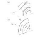
以下、フィルタアセンブリ16の主筒14に対する組付けは例えば次のようにして行われる。すなわち、図5(a)に示すように、セラミックセパレータ18に金属弾性部材74を外挿し、さらにそのセラミックセパレータ18の前端側を主筒14に挿入する。一方、フィルタアセンブリ16は図4に示すように予め組み立てておき、これを図5(a)に示すように、そのフィルタ保持部51においてセラミックセパレータ18及び主筒14の外側から被せる。なお、酸素検出素子2及び発熱体3等(図1)は主筒14内に予め組みつけておき、それらからのリード線(4本あるうち20,21のみを図示)はセラミックセパレータ18のセパレータ側リード線挿通孔72(図3)に通し、さらにフィルタ保持部51の後端側開口部から外側に延出した状態にしておく。
【0047】
続いて、図5(b)に示すように、主筒14とフィルタアセンブリ16とに軸方向の圧縮力を付加する。これにより、金属弾性部材74はフィルタ保持部51とセラミックセパレータ18のセパレータ側支持部73との間で圧縮変形し、セラミックセパレータ18を主筒14とフィルタ保持部51との間で挟み付けるための付勢力を発生する。そして、この状態を維持しつつ、図5(c)に示すように、フィルタ保持部51と主筒14とに加締め部76を形成し、両者を結合する。次いで、図5(d)に示すように、フィルタ保持部51の後端側開口部に弾性シール部材17を嵌め入れ、さらに防護カバー64を被せるとともに、同図(e)に示すように加締め部66及び67を形成して組立てが終了する。
【0048】
また、加締め部76は、例えば図6に概念的に示すような加締め装置79を用いて形成することができる。図6(a)に示すように、該加締め装置79は、それぞれフィルタ保持部51を周方向外側から圧縮する複数の加締めパンチ81を含み、これらの先端面は互いに連なって円筒面をなす。そして、図6(b)に示すように、これら加締めパンチ81はフィルタ保持部51の外周面に対し、その半径方向に互いに一体的に接近・離間するようになっている。
【0049】
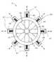
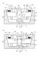
図7は、加締め装置79のより具体的な構成の一例を示す平面図である。すなわち、該加締め装置79は、リング状のパンチホルダ86と、そのパンチホルダ86の周方向に沿って配置されるとともに、それぞれ該パンチホルダ86を半径方向に進退可能に貫通する複数のパンチセグメント85とを有するパンチアセンブリ89を備える。また、各パンチセグメント85の後端部にはばね支持部87が形成され、これとパンチホルダ86の外周面との間には、該パンチセグメント85を外向きに付勢するばね部材88が配置される。一方、図8(a)に示すように、このパンチアセンブリ89に対応して、内周面91が底面側で縮径するテーパ面とされた受けユニット90が設けられ、その底面中央にはワーク挿通孔94を有する位置決め突出部93が形成されている。
【0050】
そして、主筒14にフィルタアセンブリ16を被せた状態のワークWを位置決め突出部93に対し、プロテクタ100をワーク挿通孔94に挿入する形でセットする。このとき、主体金具9が位置決め突出部93上面で支持され、ワークWは受けユニット90の底面中央に対し直立状態で保持される。そして、パンチアセンブリ89は、受けユニット90の内側に同軸的にセットされ、各パンチセグメント85がワークWを取り囲んだ状態となる。また、パンチセグメント85の外側端面92には、受けユニット90の内周面91に対応するテーパが付与されている。
【0051】
この状態で、フィルタアセンブリ16を主筒14に向けて図示しない加圧機構により押し込み(図5(b))、さらにパンチアセンブリ89を受けユニット90の底面に向けて押し込むと、図8(b)に示すように、テーパ状に形成された外側端面92と内周面91との間のカム作用により、各パンチセグメント85は対応するばね88の圧縮を伴いながら一斉にワークWに向けて接近し、加締め部76を形成する。
【0052】
上記補助フィルタ保持部51の外側には、筒状の防護カバー64がこれを覆うように設けられている。この防護カバー64は、フィルタ53への直接的な液滴の噴射あるいは油や汚れ等の付着物の付着を阻止ないし抑制する働きをなす。該防護カバー64は、例えば気体導入孔52(あるいは補助気体導入孔55)に対応する位置においてフィルタ53との間に気体滞留空間65を生じるように配置され、軸方向において気体導入孔52を挟んだ両側部分が、フィルタ保持部51の外面に対しカバー接合部としての加締め部66,67により接合されている。そして、その軸方向前方側の加締め部66に対応する位置において、フィルタ保持部51との間には、気体滞留空間65を外部と連通させてこれに外気を導入する外部連通部68が形成されている。
【0053】
具体的には、図4に示すように、フィルタ保持部51の第一部分61の外周面に、該フィルタ保持部の軸方向に延びる溝部69が周方向に沿って所定の間隔で複数形成され、これら溝部69が外部連通部を構成している。そして、図9及び図10に示すように、防護カバー64をフィルタ保持部51の第一部分61に向けて加締めることにより、各溝部69をその配列方向に横切るように、かつ溝部69の底部において防護カバー64と第一部分61との間に隙間70が残留するように上記加締め部66が環状形態で形成されている。この構造においては、図10に示すように、防護カバー64とフィルタ保持部51の第一部分61との間において、各溝部69に形成される隙間70の前方側開口部71から、該隙間70を通って気体滞留空間65へ外気が導かれることとなる。一方、加締め部67は第二部分62の末端部外周面に形成されている。なお、加締め部66は、セラミックセパレータ18の、セパレータ側支持部73の外周面に対応する位置に形成されている。これにより、加締め部形成の際の圧縮力をセパレータ側支持部73で受けることができるので、該加締め部66の形成を確実に行うことができる。
【0054】
以下、酸素センサ1の作用について説明する。
上記図1の酸素センサ1においては、前述の通りフィルタアセンブリ16のフィルタ53を介して基準ガスとしての大気が導入される一方、酸素検出素子2の外面にはプロテクタ100のガス透過口103〜106を介して導入された排気ガスが接触し、該酸素検出素子2には、その内外面の酸素濃度差に応じて酸素濃淡電池起電力が生じる。そして、この酸素濃淡電池起電力を、排気ガス中の酸素濃度の検出信号として電極層2b,2cからリード線21,20を介して取り出すことにより、排気ガス中の酸素濃度を検出できる。
【0055】
ここで、主筒14の硬度H1とフィルタ保持部51の硬度H2とを前記値に設定することにより、前述の工程で形成される加締め部76の気密性(シール性)及びその高温耐久性が向上する。その結果、例えば熱衝撃等が繰返し加わった場合でも加締め部76の緩み等が生じにくくなり、水しぶき等がかかった場合でもその主筒14内への漏れ込みが効果的に阻止される。フィルタ保持部51のビッカース硬度を160以上に高めることにより、得られる加締め部76の硬度が高められる結果、熱サイクル等が付加された際の加締め部76に生ずる熱応力変形が抑制され、加締めの緩み等が生じにくくなって気密性が向上することが、その要因として推測される。
【0056】
この場合、主筒14のビッカース硬度を300以上とさらに高い値に設定し、加えてフィルタ保持部51との硬度差が50以上となるようにすることで、上記のように硬度の高いフィルタ保持部51を主筒14に向けて加締めた場合に、主筒14はその加締め力を十分に受けとめることができるようになり、さらに密着力の高い加締め部形成が可能となる。
【0057】
他方、上記酸素センサ1の構成においては、フィルタアセンブリ16の組立てが、酸素検出素子2などのケーシング10内への組付けとは独立に行われるので、リード線が邪魔になったりせず、組立作業を極めて能率的に行うことができる。また、ケーシング10内への部品の組付けと、フィルタアセンブリ16の組立てとを並行して行えるので、生産性が飛躍的に向上する。さらに、フィルタ53の組付け不良などが生じても、フィルタアセンブリ16の段階で不良が発見できれば、センサ完成品に該不良の影響が及ばず、部品の無駄等が生じにくい。
【0058】
なお、図11により示す主体金具9の各部の寸法は、例えば以下のように設定できる。K1:27.6mm、K2:14.8mm、K3:12.8mm、K4:9mm、K5:3.8mm、K6:2mm、K7:1mm、K8:11.9mm、K9:8.6mm、K10:9mm、K11:21.1mm、K12:6.5mm、K13:φ22mm、K14:φ16.88mm、K15:φ9.48mm、K16:φ7.5mm、K17:φ16.5mm、K18:φ11.6mm、K19:φ16mm。
【0059】
他方、図1において、センサ1の全長L1は約75mmであり、主体金具9のガスケットGの受け面9dから、プロテクタ100の先端面までの長さL2は約29mmである。また、主筒14の内径は14.2mm程度である。
【0060】
なお、図12に示すように、アセンブリ連結加締め部75は、上記加締め部76を主加締め部76として、その主加締め部76よりも酸素検出素子2の先端部に近い側に、角状断面(本実施例では八角形状断面)の補助加締め部77を回転阻止部として形成した2重加締め部として構成することもできる。これにより、次の効果が達成される。すなわち、主加締め部76においては、主筒14とフィルタ保持部51との間の接触面が円筒状面となるので気密性に優れ、それらの間から主筒14内に水等が漏れ込むことを確実に阻止する役割を果たす。しかしながら、図14(b)に模式的に示すように、主筒14とフィルタ保持部51に外部からの衝撃等により強い捩じり力が作用した場合に、円筒状の接触面では両者の間に相対回転による滑りが発生して気密性が損なわれる可能性もありうる。
【0061】
そこで上述のような補助加締め部77を形成すれば、その接触面が図14(a)に示すように角筒状に形成されていることから、上述のような捩じり力が作用しても主筒14とフィルタ保持部51との間の相対的な回転が生じにくい。その結果、主加締め部76においてもそのような相対回転が生じることが効果的に阻止され、主筒14とフィルタ保持部51との間の気密性を一層確実とすることができる。なお、主加締め部76と補助加締め部77とは、軸線方向における位置関係を入れ換えて形成してもよいが、酸素センサ1の先端側は高温にさらされることが多いので、気密性確保が優先される主加締め部76がそのような熱源から遠くなる上記配置関係がより望ましいといえる。
【0062】
また、この場合のアセンブリ連結加締め部75は、例えば図13に概念的に示すような加締め装置79を用いて形成することができる。図13(a)及び(b)に示すように、該加締め装置79は、それぞれフィルタ保持部51を周方向外側から圧縮する複数の加締めパンチ81ないし83を含むとともに、同図(c)に示すように、フィルタ保持部51の軸線方向において所定距離だけ隔たった位置関係で配置される第一及び第二の加締めパンチユニット80及び82を備えている。ここで、第一の加締めパンチユニット80は主加締め部76を形成するためのものであり、各加締めパンチ81の先端面は互いに連なって円筒面をなす。一方、第二の加締めパンチユニット82は補助加締め部77を形成するためのものであり、各加締めパンチ83の先端面は互いに連なって八角筒状面をなす。そして、図13(c)に示すように、これら加締めパンチ81,83は、それぞれ対応するもの同士が連結部84によって連結されてパンチセグメント85を形成し、フィルタ保持部51の外周面に対し、その半径方向に互いに一体的に接近・離間するようになっている。
【0063】
そして、フィルタ保持部51の周囲に配置されたこれらパンチセグメント85を一斉にフィルタ保持部51に向けて接近させることにより、フィルタ保持部51には主加締め部76と補助加締め部77とが一括して形成されることとなる。この方式によれば、主加締め部76と補助加締め部77とが1回の加締め工程により同時形成されるので能率的であるばかりでなく、次のような効果も合わせて達成される。すなわち、加締めパンチによる圧縮により、フィルタ保持部51が主筒14に向けて局所的に食込みつつ圧接されて加締め部が形成されるのであるが、その圧接部の周囲においてフィルタ保持部51には、食込変形に伴うしわ寄せ部あるいは浮き上がり部が形成されやすい。ここで、主加締め部76と補助加締め部77とを順次的に形成した場合、後で形成する加締め部によるしわ寄せ部あるいは浮き上がり部の影響が先に形成した加締め部に及び、気密性が損なわれる問題が生じやすい。しかしながら、上述のように加締め部76,77を同時に形成するようにすれば、しわ寄せ部あるいは浮き上がり部の影響をそれら加締め部76及び77の間の領域にプールすることができ、ひいてはいずれの加締め部76,77においても十分な密着性すなわち気密性を確保することができるようになる。
【0064】
なお、上記補助加締め部77以外にも、例えば図15に示すように、フィルタ保持部51から主筒14側に向けて食い込む食込部78を周方向に沿って所定の間隔で形成したものも回転阻止部として機能しうる。
【0065】
また、以上説明した本発明のセンサの構造は、酸素センサ以外のガスセンサ、例えばHCセンサやNOXセンサなどにも同様に適用できる。
【0066】
【実施例】
以下、本発明の効果を確認するために以下の実験を行った。
まず、図16(a)に示すように、図1のセンサ1の主筒14及びフィルタ保持部51に使用されたものと同寸法及び同材質のステンレス鋼冷間加工管材(SUS304L)を、内筒部材14’及び外筒部材51’として、実験に必要な数量だけ用意した(ただし、外筒部材51’には、図3等における気体流通孔52に相当するものは形成していない)。ここで、内筒部材14’と外筒部材51‘(後にフィルタ保持部51となる)について、後述する加締め部76’の形成予定位置にて測定したビッカース硬度は、前者(H1)、後者(H2)共に平均値にてHv400(範囲:Hv375〜425)である。
【0067】
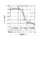
次に、両部材を窒素雰囲気中で550〜800℃の各種温度にて軟化焼鈍処理を施し(焼鈍時間60分)、H1をHv130〜410、同じくH2をHv130〜400の各種値にて調整した。なお、図18は、内筒部材14’について得られた、処理温度と処理後の硬度H1との関係を示すものである。すなわち、焼鈍処理後の部材の硬度は焼鈍温度に対して必ずしも直線的に変化せず、温度の上昇に対して620℃前後のある温度までは硬度の変化は比較的小さいが(第一温度域)、その温度に到達すると、700℃程度までの比較的狭い特定の温度域にて硬度が急激に減少し(第二温度域)、それよりも高温側では再び温度上昇に対する硬度変化が鈍くなる(第三温度域)という挙動をとっていることがわかる。
【0068】
次いで、上記のようにして得られた各種硬度の内筒部材14’と外筒部材51’とを組み合わせ、図16(a)に示すように、それぞれ内筒部材14’を外筒部材51’内に軸方向に挿入することにより、図1と同じ配置形態で重なり部を形成した。なお、この重なり部の軸線方向の長さL10は8mm以上であり、該重なり部における内筒部材14’の内径D1は12.2mm、同じく厚さt1は0.8mmである。また、外筒部材51’の厚さt2は0.3mmである。そして、図16(b)に示すように、その重なり部に対し、図1のセンサと同様の加締め部76’を、図7及び図8に示したものと同様の加締め装置により形成し、試験組立体Qを作製した。なお、加締めの圧力は11ton以上であり、加締め部76’の幅w1は約3mmとした。
【0069】
そして、図17に示すように、その試験組立体Qの軸線方向両側の開口部をゴム製の栓体J1及びJ2で塞ぐとともに、その内筒部材14’側の栓体J1に空気供給管を差し込み、さらに試験組立体Q全体を水槽内にて水没させた。そして、その状態で、上記空気供給管を介して試験組立体Qの内側空間にゲージ圧1.0kgf/cm2にて圧縮空気を送り込み、内筒部材14’と外筒部材51’との隙間からの空気漏れがあるか否かを目視にて観察するとともに、空気供給管の中間に設けた体積流量計によりその漏れ流量β(cc/分)を測定し、加締め部76’及び補助加締め部77’の気密性評価を行った。なお、評価は、漏れ流量βが
0.1cc/分以下(A)、
0.5cc/分以下(B)、
10cc/分以下(D)、
100cc/分以下(E)、
100cc/分を超える(F)
の5段階で行い、A及びBを合格とした。図19は、縦軸に内筒部材の硬度H1を、横軸に外筒部材の硬度H2を取り、各硬度の組み合わせ毎の評価結果を示すものである。すなわち、内筒部材の硬度H1がHv170以上、外筒部材の硬度H2がHv130以上、及び両者の硬度差H1−H2が50以上の比較的広い範囲で、良好な気密性が得られていることがわかる。
【0070】
次に、熱衝撃耐久試験として、各試験組立体Qを大気中にて500℃に60分加熱した後、水中に投じて急冷するサイクルを20回繰り返し、同様の気密性評価試験を行った。なお、評価は、
0.1cc/分以下(A)、
0.5cc/分以下(B)、
1.0cc/分以下(C)
10cc/分以下(D)、
100cc/分以下(E)、
100cc/分を超える(F)
の6段階で行い、A〜Cを合格とした。図20は、縦軸に内筒部材の硬度H1を、横軸に外筒部材の硬度H2を取り、各硬度の組み合わせ毎の評価結果を示すものである。すなわち、内筒部材の硬度H1をHv250〜430、外筒部材の硬度H2をHv160〜330、両者の硬度差H1−H2を30以上とした本発明の範囲においては、熱衝撃を加えた後も加締め部が良好な気密性を維持していることがわかる。
【図面の簡単な説明】
【図1】本発明の一実施例としての酸素センサの縦断面図。
【図2】図1の、酸素検出素子の検出部付近を拡大して示す断面図。
【図3】図1のフィルタアセンブリの部分を拡大して示す断面図。
【図4】フィルタアセンブリの正面部分断面図。
【図5】図1の酸素センサの組立工程説明図。
【図6】加締め装置の概念図。
【図7】その要部を示す平面模式図。
【図8】同じく側面断面模式図。
【図9】フィルタアセンブリと防護カバーとの間の加締め部の平面断面図及びその部分拡大図。
【図10】同じくその部分拡大縦断面図。
【図11】主体金具の寸法説明図。
【図12】補助加締め部を有するアセンブリ連結加締め部の拡大図、そのB−B及びC−C断面図。
【図13】加締め装置の概念図。
【図14】アセンブリ連結加締め部における加締め部と補助加締め部の作用説明図。
【図15】回転阻止部の変形例を示す平面断面図。
【図16】実施例の実験にて使用した試験組立体の作製工程説明図。
【図17】加締め部の気密性評価試験方法の説明図。
【図18】内筒部材の焼鈍処理温度と処理後のビッカース硬度測定値との関係を示すグラフ。
【図19】各内筒部材と外筒部材との硬度の組み合わせにおける気密性評価試験を示すグラフ(加熱急冷サイクル付加前)。
【図20】各内筒部材と外筒部材との硬度の組み合わせにおける気密性評価試験を示すグラフ(加熱急冷サイクル付加後)。
【符号の説明】
1 酸素センサ(ガスセンサ)
2 酸素検出素子
9 主体金具
10 ケーシング
14 主筒(内筒部材)
51 フィルタ保持部(外筒部材)
76 アセンブリ連結加締め部(加締め部)[0001]
BACKGROUND OF THE INVENTION
The present invention relates to oxygen sensors, HC sensors, NOX The present invention relates to a gas sensor for detecting a component to be detected in a gas to be measured, such as a sensor.
[0002]
[Prior art]
2. Description of the Related Art Conventionally, as a gas sensor as described above, a gas sensor having a structure in which a rod-shaped or cylindrical detection element having a detection portion for detecting a detected component formed at the tip is arranged inside a metal casing is known. . The metal casing includes a metal shell having a sensor mounting screw portion formed on the outer peripheral surface, a protector coupled to the metal shell so as to cover the detection portion of the detection element protruding from one end of the metal shell, It is coupled to the metal shell from the opposite side of the protector, and is connected to the inner cylinder member that covers the detection element extending to the rear of the metal shell, and further to the rear end of the inner cylinder member. It is configured by combining a plurality of cylindrical bodies such as an outer cylinder member that extends from the opening on the rear side.
[0003]
Among these, the inner cylinder member and the outer cylinder member are made of, for example, stainless steel, but in many sensors, these are often coupled by the following crimp bonding. That is, the end of the outer cylinder member is overlapped with the corresponding end of the inner cylinder member from the outside to form an overlapping portion, and the outer cylinder member is caulked in the circumferential direction toward the inner cylinder member in the overlapping portion. An annular caulking portion is formed so that both are hermetically coupled.
[0004]
By the way, when caulking and joining the inner cylinder member and the outer cylinder member as described above, it is possible to adjust the hardness of both members prior to caulking, and the airtightness is excellent because rattling and loosening are less likely to occur. This is important in obtaining a bonded state. For example, in Japanese Patent Application Laid-Open No. 9-210953, when the inner cylinder member and the outer cylinder member of the oxygen sensor are made of stainless steel, the Vickers hardness of the inner cylinder member (inner cover) is Hv150 to 350, the outer cylinder member ( It is described that by adjusting the Vickers hardness of the outer cover) to
[0005]
[Problems to be solved by the invention]
By the way, a gas sensor, for example, an oxygen sensor is often used by being attached to an exhaust pipe or an exhaust manifold through which high-temperature exhaust gas circulates. Sometimes the temperature rises to several hundred degrees Celsius, so a fairly severe thermal shock is repeatedly applied. However, in the above publication, the influence of vibration addition and flooding (or submergence) on the caulking joint state is discussed, but there is little detailed mention about the influence of the above-described thermal shock addition. . And as a result of intensive studies by the present inventors, when the values described in the above publication are adopted as the hardness values of the outer cylinder member and the inner cylinder member, the caulking joint portion of the sensor has added a severe thermal history. Thus, it has been found that the crimped joint cannot always maintain good airtightness.
[0006]
An object of the present invention is to have a structure in which an inner cylinder member and an outer cylinder member that cover a detection element are joined by caulking, and the caulking portion has a good airtightness even in a use environment where thermal shock is easily applied. An object of the present invention is to provide a gas sensor capable of maintaining the characteristics.
[0007]
[Means for solving the problems and actions / effects]
In order to solve the above problems, the gas sensor of the present invention is
A detection element for detecting a component to be detected in a gas to be measured (a gas to be measured) having a rod-like or cylindrical shape in which a detection part is formed at the tip part;
In a state in which the gas to be measured is allowed to flow to the detection unit, a cylindrical casing that covers the outside of the detection element is provided,
The casing is configured to include at least two cylindrical portions arranged adjacent to each other in the axial direction, and one of the two cylindrical portions (hereinafter referred to as an inner cylindrical member) at the corresponding end is the other. It is arranged so as to produce an overlapping portion in a form located inside the thing (hereinafter referred to as the outer cylinder member),
The Vickers hardness H1 of the inner cylinder member is
[0008]
According to the above-described configuration of the gas sensor of the present invention, by setting the hardness of the inner cylinder member and the outer cylinder member as described above, the crimped portion has a good airtightness even in a usage environment where thermal shock or the like is easily applied. It is possible to maintain sex.
[0009]
An important point in the configuration of the present invention is that the Vickers hardness H2 of the outer cylinder member is first set to Hv 160 or higher, for example, higher than the value disclosed in the above publication. That is, since the hardness of the caulking portion is increased by increasing the Vickers hardness of the outer cylinder member, the thermal stress deformation generated in the caulking portion when a heat cycle is added is suppressed, and loosening or the like is less likely to occur, and the airtightness is improved. It is considered a thing. Then, the Vickers hardness H1 of the inner cylinder member is set to a higher value of Hv250 or more, and in addition, the hardness difference H1−H2 with the outer cylinder member is set to 30 or more, so that the hardness can be increased as described above. When a high outer cylinder member is caulked, the inner cylinder member can sufficiently receive the caulking force, and a caulking portion with high adhesion can be formed.
[0010]
When the Vickers hardness H2 of the outer cylinder member is less than Hv160, the thermal shock resistance of the crimped portion is lowered, and sufficient airtightness cannot be ensured when repeated thermal cycles are applied. Further, when the hardness difference H1-H2 with the inner cylinder member is less than 30, the inner cylinder member cannot sufficiently receive the caulking force, causing undesired strong deformation, and caulking deformation of the outer cylinder member. Becomes insufficient, leading to a problem that the airtightness of the obtained crimped portion is impaired. In addition, if the Vickers hardness H1 of the inner cylinder member is less than Hv250 or the Vickers hardness H2 of the outer cylinder member exceeds Hv330, the thermal shock resistance of the swaged portion is lowered, which is sufficient when repeated thermal cycles are applied. Airtightness cannot be secured. The reason is that, first, when the Vickers hardness H1 of the inner cylinder member is less than Hv250, the absolute value of the rigidity of the inner cylinder member is insufficient. It is thought that. On the other hand, when the Vickers hardness H2 of the outer cylinder member exceeds Hv330, the rigidity of the outer cylinder member becomes too high, and the deformation at the time of caulking becomes insufficient, or it is not possible when forcibly trying to caulk. It is considered that uniform deformation and cracking are likely to occur, and the airtightness is similarly impaired. The hardness difference H1-H2 is more preferably 50 or more.
[0011]
Next, the thickness of the inner cylinder member is preferably 0.6 to 1.0 mm, and the thickness of the outer cylinder member is preferably 0.2 to 0.6 mm. When the thickness of the inner cylinder member is less than 0.6 mm, even if the hardness H1 is secured to Hv250 or higher, the receiving of the caulking force becomes insufficient, and the airtightness of the caulking part may be impaired. Further, when the thickness of the inner cylinder member exceeds 1.0 mm, the caulking process may be difficult. On the other hand, when the thickness of the outer cylindrical member is less than 0.2 mm, deformation due to insufficient strength of the member is likely to occur. Further, if the thickness of the outer cylinder member exceeds 0.6 mm, the caulking force is less likely to act on the inner cylinder member, and it may be difficult to obtain a sound caulking portion.
[0012]
Further, according to the study by the present inventors, as long as a hardness difference of 30 or more (preferably 50 or more) occurs with the inner cylinder member, at least Hv160 is secured as the hardness H2 of the outer cylinder member. Thus, it has been found that when the hardness H1 of the inner cylinder member is up to Hv430, the thermal shock resistance of the crimped portion can be ensured satisfactorily regardless of the level. This means that as the hardness level of the inner cylinder member increases, the hardness range of the outer cylinder member from which a good crimped portion can be obtained is expanded, in other words, the hardness of the outer cylinder member varies somewhat due to process factors. Even in this case, it means that a good crimped portion excellent in thermal shock resistance is easily obtained. Specifically, by setting the hardness H1 of the inner cylinder member to Hv300 or more, the hardness range of the outer cylinder member that can form a good crimped portion is significantly expanded, and process management is facilitated. In this respect, the hardness H1 of the inner cylinder member is more preferably set to Hv330 or more. In addition, as a material of the inner cylinder member or the outer cylinder member, for example, an iron-based material that can be cold-worked such as austenitic steel can be exemplified. In this case, the hardness level is generally in a range of
[0013]
On the other hand, when the outer cylinder member is manufactured by cold working such as forging, drawing or deep drawing of austenitic stainless steel, the Vickers hardness H2 is more preferably adjusted in the range of Hv175 to 275. It is good to do. This is due to the following reason.
[0014]
That is, since the member after cold working is in a high hardness state that is unsuitable for caulking because of the progress of work hardening, it is processed prior to caulking the member. It is desirable to anneal (anneal) this at an appropriate temperature so that it has a hardness range suitable for the above. In this case, the hardness of the cold-worked material after annealing does not necessarily change linearly with respect to the annealing temperature, but the change in hardness is relatively small up to a certain temperature with respect to the temperature rise (first temperature range). When the temperature is reached, the hardness suddenly decreases in a relatively narrow specific temperature range (second temperature range), and on the higher temperature side, the hardness change with respect to the temperature rise becomes slow again (third temperature range). Take behavior.
[0015]
By setting the Vickers hardness H2 of the outer cylinder member within the above range, it becomes possible to adjust the hardness of the member by annealing in the third temperature range where the hardness change is relatively small or the second temperature range high temperature side. Even if the annealing temperature deviates somewhat, a hardness level suitable for caulking can be stably obtained. In some cases, the inner cylinder member can have a hardness in the range of
[0016]
As a specific material of the inner cylinder member or the outer cylinder member, it is desirable to use stainless steel as described above from the viewpoint of ensuring corrosion resistance. Specifically, there are various stainless steels described in JIS: G4304. For example, SUS201, SUS202, SUS301, SUS301J, SUS302, SUS302B, SUS304, SUS304L, SUS304N1, SUS304N2, SUS304LN, SUS305, SUS309S, SUS310S, SUS316, Austenitic stainless steel such as SUS316L, SUS316N, SUS316LN, SUS316J1, SUS316J1L, SUS317, SUS317L, SUS317J1, SUS321, SUS347, and SUSXM15J1, stainless steel such as SUS329J2 and SUS329J2 (Auste SUS405, SUS410L, SUS429, SUS430, SUS430LX, SUS434, SUS436L, SUS444, SUS447J1, SUSXM27 and other ferritic stainless steels (not hardened by heat treatment and exhibit ferrite structure) Stainless steel), precipitation hardened stainless steel such as SUS631 (stainless steel that can precipitate and harden compounds mainly composed of these elements by heat treatment by adding elements such as aluminum and copper), etc. It can be illustrated.
[0017]
In addition, the concept of “stainless steel” in the present invention includes heat resistant steel exemplified below.
(1) Austenitic heat resistant steel
For example, JIS: G4311 and G4312 have compositions defined, and examples include SUS31, SUH35, SUH36, SUH37, SUH38, SUH309, SUH310, SUH330, SUH660, SUH661, and the like. The austenitic heat-resistant steel is included in the concept of austenitic stainless steel in the present invention.
(2) Ferritic heat resistant steel
For example, JIS: G4311 and G4312 have compositions defined, and examples thereof include SUH446. The ferritic heat resistant steel is included in the concept of ferritic stainless steel in the present invention.
(3) Martensitic heat resistant steel
For example, JIS: G4311 and G4312 have compositions defined, and examples include SUS1, SUS3, SUS4, SUS11, SUS600, and SUS616. The martensitic heat resistant steel is included in the concept of martensitic stainless steel in the present invention.
[0018]
Of these, ferritic stainless steel and austenitic stainless steel can be suitably used in the present invention from the viewpoint of ease of processing (particularly cold working) and, hence, improvement of the manufacturing efficiency of the member, and the usage environment of the sensor that becomes hot and humid. In view of this, it can be said that it is particularly desirable to use austenitic stainless steel.
[0019]
In addition, in the overlapping portion of the inner cylinder member and the outer cylinder member, by crimping the outer cylinder member toward the inner cylinder member, a main crimping portion formed in an annular shape in the circumferential direction thereof, In the annular main caulking portion, it is possible to form a rotation preventing portion that prevents the outer cylinder member and the inner cylinder member from relatively rotating around their axes. According to this configuration, in the main caulking portion, since the contact surface between the inner cylinder member and the outer cylinder member becomes a cylindrical surface, it is excellent in airtightness, and water or the like enters into the inner cylinder member from between them. Leakage is reliably prevented. In addition, by forming the rotation preventing portion together with the main caulking portion, even if a torsional force around the axis acts between the inner cylindrical member and the outer cylindrical member, relative rotation between the two is performed. It is hard to occur, and as a result, the airtightness in the main caulking portion can be further ensured.
[0020]
If the rotation preventing portion is an auxiliary crimping portion formed by crimping the outer cylinder member toward the inner cylinder member on at least one side of the main crimping portion in the axial direction of the outer cylinder member, Easy to form and excellent in rotation prevention effect. Specifically, the auxiliary crimping portion can be formed in an annular shape adjacent to the main crimping portion at a predetermined interval in the axial direction of the outer cylinder member and along the circumferential direction of the outer cylinder member. The rotation prevention effect is further enhanced by forming the annular auxiliary swaged portion adjacent to the main swaged portion. In this case, more specifically, the axial cross-sectional shape of the auxiliary caulking portion can be a polygonal shape. If it carries out like this, the contact surface of an inner cylinder member and an outer cylinder member will become a rectangular tube shape, and when a torsional force will act, relative rotation between an inner cylinder member and an outer cylinder member will become difficult to produce very much. .
[0021]
The auxiliary crimping portion is preferably formed on the side closer to the detection element than the main crimping portion. That is, since the front end side of the sensor is often exposed to a high temperature, it can be said that the above-described arrangement relationship in which the main caulking portion where priority is given to airtightness is far from such a heat source is more desirable.
[0022]
The main crimping portion and the auxiliary crimping portion each include a plurality of crimping punches that compress the outer cylindrical member from the outer circumferential side, and are arranged in a positional relationship separated by a predetermined distance in the axial direction of the outer cylindrical member. These two sets of caulking punch units can be collectively formed. According to this method, the main caulking portion and the auxiliary caulking portion are formed simultaneously by a single caulking step, so that not only is efficient, but the following effects are also achieved. That is, by compression by the caulking punch, the outer cylinder member is pressed against the inner cylinder member while locally biting to form a caulking portion. A wrinkled portion or a raised portion is easily formed due to biting deformation. Here, when the main caulking portion and the auxiliary caulking portion are formed sequentially, the influence of the wrinkling portion or the floating portion due to the caulking portion to be formed later extends to the caulking portion formed earlier, and the air tightness is Problems that are spoiled tend to occur However, if both the caulking portions are formed simultaneously as described above, the influence of the wrinkled portion or the floating portion can be pooled in the region between the caulking portions, and in any caulking portion as a result. Sufficient adhesion, that is, airtightness can be secured.
[0023]
In the configuration of the gas sensor, the detection element can be configured such that the detection unit includes an oxygen concentration cell element that operates using outside air introduced into the casing as a reference gas. In this case, the inner cylinder member is a main cylinder that accommodates the detection element, and the outer cylinder member is provided as a cylindrical body that is independent of the main cylinder, and is provided substantially coaxially therewith. The filter assembly can be connected to the main cylinder from the rear side while allowing it to extend outward. The filter assembly has a cylindrical shape that is substantially coaxially connected to the main cylinder from the rear side, the inside communicates with the inside of the main cylinder, and one or more gas introduction holes are formed in the wall portion. The filter holding part formed and a filter arranged so as to block the gas introduction hole of the filter holding part and blocking the permeation of liquid and allowing the permeation of gas can be provided. In this case, outside air is introduced into the main cylinder through the filter and the gas introduction hole. In this specification, the side toward the tip in the axial direction of the oxygen detection element is referred to as “front side”, and the side toward the opposite direction is referred to as “rear side”.
[0024]
The gist of the feature of the above configuration is that the air passage structure including the filter is configured as a filter assembly independently of the main tube, and is connected and integrated with the main tube. Thereby, the following effects are achieved.
(1) The assembly of the filter assembly can be performed independently of the assembly of the oxygen detection element or the like into the main cylinder, so that the lead wire of the detection element does not get in the way, for example, and the assembly work is extremely efficient. Can be done automatically.
(2) Since the assembly of parts into the main cylinder and the assembly of the filter assembly can be performed in parallel, productivity is dramatically improved. Even if a filter assembly failure or the like occurs, if a failure can be found at the filter assembly stage, the sensor will not be affected by the failure, and parts will not be wasted.
[0025]
In the present invention, as the filter, for example, a water-permeable and air-permeable filter made of a porous resin formed of a fluororesin such as polytetrafluoroethylene can be used. Specifically, for example, a porous fibrous structure (for example, obtained by stretching an unfired molded body of polytetrafluoroethylene (hereinafter referred to as PTFE) in a uniaxial direction at a heating temperature lower than the melting point of PTFE ( For example, JP-B 42-13560, JP-B 51-18991, JP-B 56-45773, JP-B 56-17216, JP-A-145735, JP-A-59-152825, JP-A-3-221541, JP-A-7-126428, JP-A-7-196831 or the like, for example, a product using a trade name such as Gore-Tex (Japan Gore-Tex Co., Ltd.) can be used.
[0026]
A filter assembly is provided coaxially and integrally with the inside of the main cylinder so as to communicate with each other with respect to the rear side of the main cylinder, and has a filter holding portion in which one or a plurality of gas introduction holes are formed in the wall portion, and the filter The filter is disposed outside the holding portion so as to block the gas introduction hole, prevents the liquid from passing therethrough and allows the gas to pass therethrough, and is formed in a cylindrical shape disposed outside the filter. The auxiliary gas introduction hole is formed, and an auxiliary filter holding part that holds the filter between the filter holding part and the filter is provided. In this case, outside air is introduced into the main cylinder from the gas introduction hole through the filter from the auxiliary gas introduction hole. That is, the filter can be reliably held by the inner and outer filter holding portions, and the filter can be easily assembled to the filter holding portion. For example, when the filter is formed in a cylindrical shape, the filter holding unit is extrapolated from the filter holding unit, and the auxiliary filter holding unit is further fitted from the outside of the filter holding unit at a position where it does not interfere with the gas introduction hole and the auxiliary gas introduction hole. What is necessary is just to form the holding | maintenance part coupling | bond part which couple | bonds an auxiliary filter holding | maintenance part.
[0027]
A plurality of gas introduction holes and auxiliary gas introduction holes can be formed at predetermined intervals along the circumferential direction with respect to the filter holding portion and the auxiliary filter holding portion, respectively, in a positional relationship corresponding to each other in the axial intermediate portion. Thereby, it is possible to introduce the outside air from the filter assembly side into the main cylinder without any deviation. Further, for example, a cylindrical filter is disposed outside the filter holding portion so as to surround the filter holding portion, and the auxiliary filter holding portion is connected to the auxiliary filter holding portion as a holding portion coupling portion. By caulking toward the end, an annular filter caulking portion can be formed along the circumferential direction. The assembly of the filter assembly is further facilitated by using the holding portion coupling portion as an annular filter caulking portion. In addition, this cyclic | annular crimping part can be formed in the both sides which pinch | interpose the row | line | column of a gas introduction hole and an auxiliary | assistant gas introduction hole in an axial direction. In this case, in each caulking part, the edge of the filter is sandwiched between the auxiliary filter holding part and the filter holding part, thereby bypassing the filter edge from the auxiliary gas introduction hole and introducing the gas into the filter holding part. A path leading to the hole is less likely to be formed, and the possibility that water or the like leaks into the inside of the filter holding portion and thus inside the main cylinder through the passage is reduced.
[0028]
In addition, when the filter is formed in a cylindrical shape as described above and arranged along the outer periphery of the filter holding portion, the auxiliary filter holding portion is positioned so that the axial rear end edge thereof corresponds to the filter rear end edge. The filter caulking portion can be formed in the circumferential direction along the rear end edge. As a result, the filter positioned between the auxiliary filter holding part and the filter holding part can be viewed at the rear end face position. This has the following advantages. That is, when the tubular filter is extrapolated to the filter holding portion, and the auxiliary filter holding portion is further fitted in the filter holding portion while moving relative to the filter holding portion in the axial direction, the filter moves with the auxiliary filter holding portion. Position misalignment. In this case, if the filter caulking part is formed in this state, the filter is detached from the caulking part and the seal becomes incomplete, but the rear end surface part of the filter can be visually observed as described above. Thus, it is possible to easily find a caulking defect of such a filter.
[0029]
Moreover, when forming a filter crimp part in the front edge side of an auxiliary filter holding part, the filter confirmation exposure part which exposes a filter partially in the filter crimp part can also be formed. If it carries out like this, it can be discriminate | determined easily whether the filter is normally crimped in the crimping part also in the front edge side of an auxiliary filter holding | maintenance part.
[0030]
DETAILED DESCRIPTION OF THE INVENTION
Hereinafter, embodiments of the present invention will be described based on examples shown in the drawings.
FIG. 1 shows the internal structure of an oxygen sensor as an embodiment of the gas sensor of the present invention. The
[0031]
A
[0032]
In the following, the side toward the closed tip in the axial direction of the
[0033]
First, a cylindrical protector mounting portion 9a is formed in the front side opening of the
[0034]
Next, the
[0035]
Next, as shown in FIG. 3, a plurality of separator-side lead wire insertion holes 72 for inserting the
[0036]
One
[0037]
Here, when the exhaust gas temperature is sufficiently high, the
[0038]
The
[0039]
The internal
[0040]
Next, as shown in FIG. 3, the
[0041]
The
[0042]
Further, as shown in FIG. 4, the
[0043]
On the other hand, the
[0044]
Returning to FIG. 3, the
[0045]
Here, the main cylinder 14 (inner cylinder member) and the filter holding part 51 (outer cylinder member) are both made of stainless steel (SUS304L in FIG. 1), and the former Vickers hardness H1 is
[0046]
Hereinafter, the assembly of the
[0047]
Subsequently, as shown in FIG. 5B, an axial compressive force is applied to the
[0048]
Moreover, the crimping
[0049]
FIG. 7 is a plan view showing an example of a more specific configuration of the
[0050]
Then, the workpiece W in a state where the
[0051]
In this state, when the
[0052]
A cylindrical
[0053]
Specifically, as shown in FIG. 4, a plurality of
[0054]
Hereinafter, the operation of the
In the
[0055]
Here, by setting the hardness H1 of the
[0056]
In this case, the Vickers hardness of the
[0057]
On the other hand, in the configuration of the
[0058]
In addition, the dimension of each part of the
[0059]
On the other hand, in FIG. 1, the total length L1 of the
[0060]
As shown in FIG. 12, the assembly
[0061]
Therefore, if the
[0062]
Moreover, the assembly
[0063]
Then, by bringing these
[0064]
In addition to the
[0065]
Further, the structure of the sensor of the present invention described above is a gas sensor other than an oxygen sensor, such as an HC sensor or NO.X The same applies to sensors.
[0066]
【Example】
Hereinafter, the following experiment was performed in order to confirm the effect of the present invention.
First, as shown in FIG. 16 (a), stainless steel cold-worked tubing (SUS304L) having the same dimensions and the same materials as those used for the
[0067]
Next, both members were softened and annealed at various temperatures of 550 to 800 ° C. in a nitrogen atmosphere (annealing
[0068]
Subsequently, the
[0069]
Then, as shown in FIG. 17, the openings on both axial sides of the test assembly Q are closed with rubber plugs J1 and J2, and an air supply pipe is connected to the plug J1 on the inner cylinder member 14 'side. Further, the entire test assembly Q was submerged in a water tank. In that state, a gauge pressure of 1.0 kgf / cm is introduced into the inner space of the test assembly Q through the air supply pipe.2 Compressed air is fed in and visually observed whether there is an air leak from the gap between the inner cylinder member 14 'and the outer cylinder member 51', and by a volumetric flow meter provided in the middle of the air supply pipe The leakage flow rate β (cc / min) was measured, and the airtightness of the crimped
0.1 cc / min or less (A),
0.5 cc / min or less (B),
10 cc / min or less (D),
100 cc / min or less (E),
Over 100cc / min (F)
A and B were set to pass. FIG. 19 shows the evaluation results for each combination of hardness, with the vertical axis representing the hardness H1 of the inner cylinder member and the horizontal axis representing the hardness H2 of the outer cylinder member. That is, good airtightness is obtained in a relatively wide range in which the hardness H1 of the inner cylinder member is
[0070]
Next, as a thermal shock endurance test, each test assembly Q was heated to 500 ° C. for 60 minutes in the atmosphere, and then a cycle in which it was poured into water and rapidly cooled was repeated 20 times, and a similar airtightness evaluation test was performed. The evaluation is
0.1 cc / min or less (A),
0.5 cc / min or less (B),
1.0cc / min or less (C)
10 cc / min or less (D),
100 cc / min or less (E),
Over 100cc / min (F)
It was performed in six stages, and A to C were regarded as passing. FIG. 20 shows the evaluation results for each combination of hardness, with the vertical axis representing the hardness H1 of the inner cylinder member and the horizontal axis representing the hardness H2 of the outer cylinder member. That is, within the scope of the present invention in which the hardness H1 of the inner cylinder member is
[Brief description of the drawings]
FIG. 1 is a longitudinal sectional view of an oxygen sensor as one embodiment of the present invention.
2 is an enlarged cross-sectional view of the vicinity of a detection portion of the oxygen detection element in FIG.
3 is an enlarged cross-sectional view of a portion of the filter assembly of FIG.
FIG. 4 is a front partial cross-sectional view of a filter assembly.
5 is an explanatory diagram of an assembly process of the oxygen sensor in FIG. 1. FIG.
FIG. 6 is a conceptual diagram of a caulking device.
FIG. 7 is a schematic plan view showing the main part.
FIG. 8 is a schematic side sectional view.
FIG. 9 is a plan sectional view and a partially enlarged view of a caulking portion between a filter assembly and a protective cover.
FIG. 10 is a partially enlarged longitudinal sectional view of the same.
FIG. 11 is an explanatory diagram of dimensions of the metal shell.
FIG. 12 is an enlarged view of an assembly connecting caulking portion having an auxiliary caulking portion, and its BB and CC cross-sectional views.
FIG. 13 is a conceptual diagram of a caulking device.
FIG. 14 is an operation explanatory view of a caulking portion and an auxiliary caulking portion in the assembly coupling caulking portion.
FIG. 15 is a plan cross-sectional view showing a modification of the rotation blocking unit.
FIG. 16 is an explanatory diagram of a manufacturing process of a test assembly used in an experiment of an example.
FIG. 17 is an explanatory diagram of an airtightness evaluation test method for a caulking portion.
FIG. 18 is a graph showing the relationship between the annealing temperature of the inner cylinder member and the measured Vickers hardness value.
FIG. 19 is a graph showing an airtightness evaluation test in a combination of hardnesses of each inner cylinder member and outer cylinder member (before heating and cooling cycle addition).
FIG. 20 is a graph showing an airtightness evaluation test in a combination of hardnesses of each inner cylinder member and outer cylinder member (after heating and cooling cycle is added).
[Explanation of symbols]
1 Oxygen sensor (gas sensor)
2 Oxygen detection element
9 Main metal fittings
10 Casing
14 Main tube (inner tube member)
51 Filter holding part (outer cylinder member)
76 Assembly connecting caulking part (caulking part)
Claims (5)
Translated fromJapanese前記検出部への被測定ガスの流通を許容した状態で、前記検出素子の外側を覆う筒状のケーシングとを備え、
そのケーシングは、軸線方向に隣接配置される2つの筒状部を少なくとも含んで構成され、それら2つの筒状部は、対応する端部において一方のもの(以下、内筒部材という)が他方のもの(以下、外筒部材という)の内側に位置する形で重なり部を生ずるように配置されており、
前記内筒部材のビッカース硬度H1がHv250〜430、前記外筒部材のビッカース硬度H2がHv160〜330、両者の硬度差H1−H2が30以上とされ、前記重なり部においてそれら内筒部材と外筒部材とが、周方向に形成された加締め部により気密状態で接合されていることを特徴とするガスセンサ。A detection element for detecting a component to be detected in a gas to be measured (hereinafter referred to as a gas to be measured) having a rod shape or a cylindrical shape in which a detection portion is formed at a tip portion;
In a state in which the gas to be measured is allowed to flow to the detection unit, a cylindrical casing that covers the outside of the detection element is provided,
The casing is configured to include at least two cylindrical portions arranged adjacent to each other in the axial direction, and one of the two cylindrical portions (hereinafter referred to as an inner cylindrical member) at the corresponding end is the other. It is arranged so as to produce an overlapping portion in a form located inside the thing (hereinafter referred to as the outer cylinder member),
The inner cylinder member has a Vickers hardness H1 of Hv250 to 430, the outer cylinder member has a Vickers hardness H2 of Hv160 to 330, and a hardness difference H1−H2 of 30 or more. A gas sensor, wherein a member is joined in an airtight state by a caulking portion formed in a circumferential direction.
Priority Applications (3)
| Application Number | Priority Date | Filing Date | Title |
|---|---|---|---|
| JP17143898AJP3703627B2 (en) | 1998-06-18 | 1998-06-18 | Gas sensor |
| EP99304708AEP0965838A1 (en) | 1998-06-18 | 1999-06-16 | Gas sensor |
| US09/334,722US6548023B1 (en) | 1998-06-18 | 1999-06-17 | Gas sensor |
Applications Claiming Priority (1)
| Application Number | Priority Date | Filing Date | Title |
|---|---|---|---|
| JP17143898AJP3703627B2 (en) | 1998-06-18 | 1998-06-18 | Gas sensor |
Publications (2)
| Publication Number | Publication Date |
|---|---|
| JP2000002684A JP2000002684A (en) | 2000-01-07 |
| JP3703627B2true JP3703627B2 (en) | 2005-10-05 |
Family
ID=15923133
Family Applications (1)
| Application Number | Title | Priority Date | Filing Date |
|---|---|---|---|
| JP17143898AExpired - LifetimeJP3703627B2 (en) | 1998-06-18 | 1998-06-18 | Gas sensor |
Country Status (3)
| Country | Link |
|---|---|
| US (1) | US6548023B1 (en) |
| EP (1) | EP0965838A1 (en) |
| JP (1) | JP3703627B2 (en) |
Families Citing this family (19)
| Publication number | Priority date | Publication date | Assignee | Title |
|---|---|---|---|---|
| DE69822968T2 (en) | 1997-11-21 | 2005-03-31 | Denso Corp., Kariya | gas sensor |
| JP2002174620A (en)* | 2000-12-07 | 2002-06-21 | Denso Corp | Gas sensor element and gas sensor |
| JP4167008B2 (en)* | 2002-05-24 | 2008-10-15 | 日本特殊陶業株式会社 | Gas detector |
| US7241370B2 (en) | 2002-08-20 | 2007-07-10 | Ngk Spark Plug Co., Ltd. | Protective covers for gas sensor, gas sensor and gas sensor manufacturing method |
| EP2940463B1 (en)* | 2003-06-30 | 2019-11-20 | NGK Spark Plug Co., Ltd. | Gassensor comprising a cylindrical protector cap |
| EP1507144B1 (en)* | 2003-07-04 | 2018-05-09 | Ngk Spark Plug Co., Ltd | Cylindrical gas sensor comprising a vibration resistant protector |
| US7178382B2 (en)* | 2003-12-24 | 2007-02-20 | Denso Corporation | Structure of gas sensor designed to reduce mechanical damage to sensor element |
| US20080017510A1 (en)* | 2004-05-26 | 2008-01-24 | Nair Balakrishnan G | NOx Gas Sensor Method and Device |
| US7114325B2 (en)* | 2004-07-23 | 2006-10-03 | Ford Global Technologies, Llc | Control system with a sensor |
| US7611612B2 (en)* | 2005-07-14 | 2009-11-03 | Ceramatec, Inc. | Multilayer ceramic NOx gas sensor device |
| JP4654987B2 (en)* | 2005-12-02 | 2011-03-23 | 株式会社デンソー | Gas sensor |
| JP4815257B2 (en)* | 2006-04-13 | 2011-11-16 | 日本特殊陶業株式会社 | Gas sensor |
| TW200827057A (en)* | 2006-12-29 | 2008-07-01 | Hon Hai Prec Ind Co Ltd | Bezel and method of making the bezel |
| WO2008103311A2 (en)* | 2007-02-16 | 2008-08-28 | Ceramatec, Inc. | Nox sensor with improved selectivity and sensitivity |
| JP2009276339A (en)* | 2008-04-16 | 2009-11-26 | Ngk Spark Plug Co Ltd | Sensor |
| JP4774110B2 (en)* | 2008-07-28 | 2011-09-14 | 日本特殊陶業株式会社 | Circuit board case |
| US9164080B2 (en) | 2012-06-11 | 2015-10-20 | Ohio State Innovation Foundation | System and method for sensing NO |
| JP6480228B2 (en)* | 2015-03-26 | 2019-03-06 | 日本碍子株式会社 | Gas sensor |
| US10969372B2 (en)* | 2017-12-11 | 2021-04-06 | Ngk Spark Plug Co., Ltd. | Gas sensor |
Family Cites Families (35)
| Publication number | Priority date | Publication date | Assignee | Title |
|---|---|---|---|---|
| CA962021A (en) | 1970-05-21 | 1975-02-04 | Robert W. Gore | Porous products and process therefor |
| US3962153A (en) | 1970-05-21 | 1976-06-08 | W. L. Gore & Associates, Inc. | Very highly stretched polytetrafluoroethylene and process therefor |
| US3930969A (en) | 1974-06-28 | 1976-01-06 | Cyprus Metallurgical Processes Corporation | Process for oxidizing metal sulfides to elemental sulfur using activated carbon |
| JPS5617216A (en) | 1979-07-24 | 1981-02-19 | Central Jidosha Kk | Plastic press die and production thereof |
| US4239505A (en) | 1979-09-07 | 1980-12-16 | Union Carbide Corporation | Purge gas conditioning of high intensity ionization system for particle removal |
| US4596837A (en) | 1982-02-22 | 1986-06-24 | Daikin Industries Ltd. | Semisintered polytetrafluoroethylene article and production thereof |
| JPS58145735A (en) | 1982-02-22 | 1983-08-30 | Daikin Ind Ltd | Method for manufacturing polytetrafluoroethylene porous material |
| JPS59152825A (en) | 1983-02-19 | 1984-08-31 | Daikin Ind Ltd | Semi-fired polytetrafluoroethylene body and its manufacturing method |
| US4578174A (en)* | 1983-05-09 | 1986-03-25 | Ngk Insulators, Ltd. | Oxygen sensor with heater |
| DE3511730A1 (en)* | 1984-07-06 | 1986-02-06 | Bosch Gmbh Robert | MEASURING PROBE FOR DETERMINING THE OXYGEN CONTENT IN GASES |
| US4818364A (en)* | 1987-04-13 | 1989-04-04 | Allied-Signal Inc. | Terminal member for 02 sensor |
| US4870855A (en)* | 1987-12-22 | 1989-10-03 | Delphian Corporation | Gas sensor protection devices and assemblies |
| JPH0689165B2 (en) | 1990-01-29 | 1994-11-09 | ダイキン工業株式会社 | Polytetrafluoroethylene porous membrane and method for producing the same |
| JP2745805B2 (en) | 1990-10-29 | 1998-04-28 | トヨタ自動車株式会社 | Manufacturing method of oxygen concentration sensor |
| JP2897471B2 (en) | 1991-07-31 | 1999-05-31 | トヨタ自動車株式会社 | Oxide semiconductor oxygen concentration sensor |
| JPH05196598A (en) | 1992-01-22 | 1993-08-06 | Toyota Motor Corp | Method of measuring oxygen sensor response time |
| JP2530276B2 (en)* | 1992-09-14 | 1996-09-04 | 株式会社森製作所 | Catalytic combustion type carbon monoxide sensor |
| US5573650A (en)* | 1993-01-28 | 1996-11-12 | Nippondenso Co., Ltd. | Gas sensor |
| DE4318789A1 (en)* | 1993-06-05 | 1994-12-08 | Bosch Gmbh Robert | Seal for a sensor element of a gas sensor |
| JP2854223B2 (en) | 1993-09-08 | 1999-02-03 | ジャパンゴアテックス株式会社 | Oil repellent waterproof ventilation filter |
| JPH07196831A (en) | 1993-12-28 | 1995-08-01 | Japan Gore Tex Inc | Polytetrafluoroethylene porous membrane and method for producing the same |
| JP3453899B2 (en) | 1995-01-25 | 2003-10-06 | 株式会社デンソー | Method and apparatus for evaluating characteristics of air-fuel ratio sensor |
| JP3221541B2 (en) | 1995-01-26 | 2001-10-22 | 日本電信電話株式会社 | Connection structure and connection method between optical waveguide and optical fiber |
| JP3624526B2 (en)* | 1995-06-07 | 2005-03-02 | 株式会社デンソー | Oxygen concentration detector |
| JPH0996622A (en)* | 1995-09-29 | 1997-04-08 | Matsushita Electric Ind Co Ltd | Gas sensor and manufacturing method thereof |
| JP3624498B2 (en)* | 1995-10-27 | 2005-03-02 | 株式会社デンソー | Air-fuel ratio sensor |
| US5874664A (en)* | 1996-01-30 | 1999-02-23 | Denso Corporation | Air fuel ratio sensor and method for assembling the same |
| JP3079985B2 (en)* | 1996-01-30 | 2000-08-21 | 株式会社デンソー | Oxygen concentration detector |
| DE19603379A1 (en)* | 1996-01-31 | 1997-08-07 | Bosch Gmbh Robert | Gas sensor |
| US5762771A (en)* | 1996-02-06 | 1998-06-09 | Denso Corporation | Air-fuel ratio sensor |
| DE19605290C2 (en)* | 1996-02-14 | 1998-02-26 | Bosch Gmbh Robert | Sensor |
| JP3863974B2 (en)* | 1996-10-31 | 2006-12-27 | 株式会社日本自動車部品総合研究所 | Gas detector |
| JP3553316B2 (en)* | 1997-05-20 | 2004-08-11 | 日本碍子株式会社 | Gas sensor |
| DE69822968T2 (en)* | 1997-11-21 | 2005-03-31 | Denso Corp., Kariya | gas sensor |
| EP0974836B1 (en)* | 1998-07-13 | 2014-01-15 | Denso Corporation | Gas sensor having improved structure for installation of protective cover |
- 1998
- 1998-06-18JPJP17143898Apatent/JP3703627B2/ennot_activeExpired - Lifetime
- 1999
- 1999-06-16EPEP99304708Apatent/EP0965838A1/ennot_activeWithdrawn
- 1999-06-17USUS09/334,722patent/US6548023B1/ennot_activeExpired - Lifetime
Also Published As
| Publication number | Publication date |
|---|---|
| US6548023B1 (en) | 2003-04-15 |
| JP2000002684A (en) | 2000-01-07 |
| EP0965838A1 (en) | 1999-12-22 |
Similar Documents
| Publication | Publication Date | Title |
|---|---|---|
| JP3703627B2 (en) | Gas sensor | |
| CN101865875B (en) | Gas sensor | |
| JP3648381B2 (en) | Gas sensor and manufacturing method thereof | |
| JP5310170B2 (en) | Gas sensor and manufacturing method thereof | |
| JP2009198422A (en) | Gas sensor | |
| JP2009002846A (en) | Gas sensor and its manufacturing method | |
| JP3885781B2 (en) | Gas sensor | |
| JP5129599B2 (en) | Gas sensor and manufacturing method thereof | |
| JP4634301B2 (en) | Gas sensor and gas sensor manufacturing method | |
| JPH11160274A (en) | Gas sensor | |
| JP6740921B2 (en) | Gas sensor | |
| CN102565152B (en) | Gas sensor | |
| JP5524944B2 (en) | Gas sensor | |
| JP2007101411A (en) | Sensor | |
| JP3660110B2 (en) | Oxygen sensor | |
| JP2008232864A (en) | Gas sensor | |
| US20080105030A1 (en) | Gas Sensor Containing a Protective Tube | |
| JP3713134B2 (en) | Oxygen sensor | |
| JP3713133B2 (en) | Oxygen sensor | |
| JP3950523B2 (en) | Oxygen sensor with heater | |
| JP2004226117A (en) | Manufacturing method of gas sensor, and gas sensor | |
| JP3705907B2 (en) | Oxygen sensor | |
| JP3705907B6 (en) | Oxygen sensor | |
| JPH1172462A (en) | Oxygen sensor | |
| JP3869534B2 (en) | Oxygen sensor |
Legal Events
| Date | Code | Title | Description |
|---|---|---|---|
| A977 | Report on retrieval | Free format text:JAPANESE INTERMEDIATE CODE: A971007 Effective date:20040712 | |
| A131 | Notification of reasons for refusal | Free format text:JAPANESE INTERMEDIATE CODE: A131 Effective date:20040908 | |
| TRDD | Decision of grant or rejection written | ||
| A01 | Written decision to grant a patent or to grant a registration (utility model) | Free format text:JAPANESE INTERMEDIATE CODE: A01 Effective date:20050620 | |
| A61 | First payment of annual fees (during grant procedure) | Free format text:JAPANESE INTERMEDIATE CODE: A61 Effective date:20050720 | |
| R150 | Certificate of patent or registration of utility model | Free format text:JAPANESE INTERMEDIATE CODE: R150 | |
| FPAY | Renewal fee payment (event date is renewal date of database) | Free format text:PAYMENT UNTIL: 20080729 Year of fee payment:3 | |
| FPAY | Renewal fee payment (event date is renewal date of database) | Free format text:PAYMENT UNTIL: 20090729 Year of fee payment:4 | |
| FPAY | Renewal fee payment (event date is renewal date of database) | Free format text:PAYMENT UNTIL: 20090729 Year of fee payment:4 | |
| FPAY | Renewal fee payment (event date is renewal date of database) | Free format text:PAYMENT UNTIL: 20090729 Year of fee payment:4 | |
| FPAY | Renewal fee payment (event date is renewal date of database) | Free format text:PAYMENT UNTIL: 20100729 Year of fee payment:5 | |
| FPAY | Renewal fee payment (event date is renewal date of database) | Free format text:PAYMENT UNTIL: 20100729 Year of fee payment:5 | |
| FPAY | Renewal fee payment (event date is renewal date of database) | Free format text:PAYMENT UNTIL: 20110729 Year of fee payment:6 | |
| FPAY | Renewal fee payment (event date is renewal date of database) | Free format text:PAYMENT UNTIL: 20110729 Year of fee payment:6 | |
| FPAY | Renewal fee payment (event date is renewal date of database) | Free format text:PAYMENT UNTIL: 20120729 Year of fee payment:7 | |
| FPAY | Renewal fee payment (event date is renewal date of database) | Free format text:PAYMENT UNTIL: 20120729 Year of fee payment:7 | |
| FPAY | Renewal fee payment (event date is renewal date of database) | Free format text:PAYMENT UNTIL: 20120729 Year of fee payment:7 | |
| FPAY | Renewal fee payment (event date is renewal date of database) | Free format text:PAYMENT UNTIL: 20130729 Year of fee payment:8 | |
| R250 | Receipt of annual fees | Free format text:JAPANESE INTERMEDIATE CODE: R250 | |
| R250 | Receipt of annual fees | Free format text:JAPANESE INTERMEDIATE CODE: R250 | |
| R250 | Receipt of annual fees | Free format text:JAPANESE INTERMEDIATE CODE: R250 | |
| R250 | Receipt of annual fees | Free format text:JAPANESE INTERMEDIATE CODE: R250 | |
| R250 | Receipt of annual fees | Free format text:JAPANESE INTERMEDIATE CODE: R250 | |
| EXPY | Cancellation because of completion of term |