JP3703250B2 - Reflective display lighting device - Google Patents
Reflective display lighting deviceDownload PDFInfo
- Publication number
- JP3703250B2 JP3703250B2JP12234397AJP12234397AJP3703250B2JP 3703250 B2JP3703250 B2JP 3703250B2JP 12234397 AJP12234397 AJP 12234397AJP 12234397 AJP12234397 AJP 12234397AJP 3703250 B2JP3703250 B2JP 3703250B2
- Authority
- JP
- Japan
- Prior art keywords
- sin
- substrate
- light
- angle
- collimator
- Prior art date
- Legal status (The legal status is an assumption and is not a legal conclusion. Google has not performed a legal analysis and makes no representation as to the accuracy of the status listed.)
- Expired - Fee Related
Links
Images


Classifications
- G—PHYSICS
- G02—OPTICS
- G02F—OPTICAL DEVICES OR ARRANGEMENTS FOR THE CONTROL OF LIGHT BY MODIFICATION OF THE OPTICAL PROPERTIES OF THE MEDIA OF THE ELEMENTS INVOLVED THEREIN; NON-LINEAR OPTICS; FREQUENCY-CHANGING OF LIGHT; OPTICAL LOGIC ELEMENTS; OPTICAL ANALOGUE/DIGITAL CONVERTERS
- G02F1/00—Devices or arrangements for the control of the intensity, colour, phase, polarisation or direction of light arriving from an independent light source, e.g. switching, gating or modulating; Non-linear optics
- G02F1/01—Devices or arrangements for the control of the intensity, colour, phase, polarisation or direction of light arriving from an independent light source, e.g. switching, gating or modulating; Non-linear optics for the control of the intensity, phase, polarisation or colour
- G02F1/13—Devices or arrangements for the control of the intensity, colour, phase, polarisation or direction of light arriving from an independent light source, e.g. switching, gating or modulating; Non-linear optics for the control of the intensity, phase, polarisation or colour based on liquid crystals, e.g. single liquid crystal display cells
- G02F1/133—Constructional arrangements; Operation of liquid crystal cells; Circuit arrangements
- G02F1/1333—Constructional arrangements; Manufacturing methods
- G02F1/1335—Structural association of cells with optical devices, e.g. polarisers or reflectors
- G02F1/1336—Illuminating devices
- G02F1/133616—Front illuminating devices
Landscapes
- Light Guides In General And Applications Therefor (AREA)
- Liquid Crystal (AREA)
- Planar Illumination Modules (AREA)
Description
Translated fromJapanese【0001】
【発明の属する技術分野】
本発明は、書籍や写真などの印刷物や、パーソナルコンピュータなどのOA機器、携帯情報端末、ポータブルビデオテープレコーダーなどの画面表示装置、又は、各種モニタに使用される反射型液晶表示装置、などに用いられる反射表示用照明装置に関するものである。
【0002】
【従来の技術】
近年、パーソナルコンピュータや携帯情報端末、ビデオテープレコーダーなどは小型化、ポータブル化が進んでおり、画像表示装置の消費電力低減が重要な課題となっている。このため、画像表示装置に反射型液晶表示装置を用いるものが多数存在している。
反射型液晶表示素子は、太陽光や室内光などの外光を反射させることにより画面の明るさを得ている。しかし、外光の少ないところでは画面に十分な明るさが得られない。そこで、外光の十分でないところにおいても画面表示可能とする照明装置の付いた反射型液晶表示装置がいくつか発明されている。
反射型液晶表示素子に取り付けられる照明装置の一例を示す。図16は従来の照明装置の断面図の模式図である。図16に示すとおり、従来の照明装置は、光源1、リフレクタ2、導光体63、補償板5によって構成される。リフレクタ2は光源1から発射された光線を平行化するために、光源1から導光体63の側面までの距離を長くしている。導光体63は、リフレクタ2より導入された光線を全反射によって伝搬する機能と、上面の溝の斜面によって光線を全反射させ、光線角度を変えることによって反射板4を照明する機能を有する。補償板5は反射板4からの反射光が導光体63を通過する際に生じる歪みを、補正する機能を有する。
【0003】
【発明が解決しようとする課題】
しかしながら、従来の照明装置は、導光体63より補償板5に透過した光線が補償板5上面にて全反射したのち再び導光体63に入射するとき、光線の一部が導光体63の上面の溝の斜面で反射するため、溝筋が見えやすいという問題点がある。また、この溝筋が見えやすいという問題点を軽減化するために、リフレクタ2によって光線を平行化しているが、平行化された光は導光体63の溝の斜面に当たらず、導光体63の光源側と反対側に到達しやすいため、照明効率が低いという問題点がある。
そこで、本発明は、かかる問題点を解決することを課題とし、溝筋が見えにくく、反射光の画像が良好に保たれ、照明効率がよい、反射表示用照明装置を提供することを目的とする。
【0004】
【課題を解決するための手段及びその作用】
上記目的を達成するために、本発明は以下のように構成している。
本発明の第1態様によれば、 光源と、前記光源からの光が入射する面である側面と互いに平行な上下面とを有する透明基板とを備え、
前記透明基板には、前記透明基板の屈折率とは異なる屈折率を有する材料を内部に有する溝が配置されるとともに、前記透明基板の屈折率をnとし、前記溝内の材料の屈折率をn1とし、反射表示用照明装置の視野角をβとするとき、
前記溝と前記透明基板の上面とのなす角のうちの鋭角θが、
(数5)
θ<sin−1(n1/n)−sin−1{(1/n)sin(β)}<90°
の条件を満たすようにしたことを特徴とする反射表示用照明装置を提供する。
【0005】
本発明の第2態様によれば、少なくとも光源と、前記光源からの光が入射する面を側面とする透明な第1の基板と、前記第1の基板の上面方向に配置された透明な第2の基板とを備えて構成され、
前記第1の基板の下面は平面であり、前記第1の基板の上面には階段状の斜面が配置され、
前記第2の基板の下面は階段状の斜面が前記第1の基板の前記上面の前記斜面と同形状で配置され、前記光源の出射口にコリメータを配置し、
前記第1の基板の屈折率をnとし、前記第1の基板と前記第2の基板の間に配置された材料の屈折率をn2とし、反射表示用照明装置の視野角をβとするとき、
前記第1の基板の前記上面および前記第2の基板の前記下面の斜面の角度のうちの鋭角θが、
(数6)
θ<sin−1(n2/n)−sin−1{(1/n)sin(β)}<90°
の条件を満たすようにするとともに、
上記斜面のピッチは、上記第1の基板の光源より遠ざかるにつれて小さくなるとともに、上記斜面長さを、上記第1の基板の光源より遠ざかるにつれて大きくなるようにしたことを特徴とする反射表示用照明装置を提供する。
【0006】
本発明の第3態様によれば、第2態様において、前記光源の出射口に配置されたコリメータの光線出射角度が±sin-1[n*sin{90−θ−sin-1(n2/n)}]以内であるようにした反射表示用照明装置を提供する。
本発明の第4態様によれば、第2又は3の態様において、前記光源の出射口に配置されたコリメータは光線入射面が平面であり、前記第1の基板の屈折率をnとし、前記第1の基板と前記第2の基板を貼り合わせている材料の屈折率をn2とし、前記コリメータの屈折率をn3とし、前記コリメータの出射面の円錐形の凹部を構成する凸部の頂角の半分の角度δが
(数7)
sin-1[n*sin{90−θ−sin-1(n2/n)}]=90−δ−sin-1[n3*sin{90−δ−sin-1(1/n3)}]
を満たす値であるとしたとき、前記コリメータの出射面が角度+δまたは角度−δの斜面が複数個配置されている反射表示用照明装置を提供する。
本発明の第5態様によれば、第2又は3の態様において、前記光源の出射口に配置されたコリメータは光線入射面が平面であり、前記第1の基板の屈折率をnとし、前記第1の基板と前記第2の基板を貼り合わせている材料の屈折率をn2とし、前記コリメータの屈折率をn3とし、前記コリメータの出射面の円錐形の凹部を構成する凸部の頂角の半分の角度δが
(数8)
δ=sin-1[n*sin{90−θ−sin-1(n2/n)}]
を満たす値であるとしたとき、前記コリメータの出射面が角度+δまたは角度−δの斜面が複数個配置されている反射表示用照明装置を提供する。
【0007】
本発明の第1〜3態様によれば、前記光源から出射された光は前記透明基板に入射し、透明基板内で全反射を繰り返しながら伝搬していく。このとき、光線は角度によって、透明基板の内部にある前記スリットによって全反射するものと、透過するものに分けられる。全反射した光線は角度を変えられ、全反射角より小さくなってしまうために透明基板の下面側に出射する。また、透過した光線は透明基板の上面で全反射し、引き続き透明基板内を伝搬するため、透明基板のスリット筋は見えにくい。また、スリットを透過し、溝筋を見えにくくするために従来必要であったコリメータが不要となるので、ほとんど全ての光線が透明基板の下側へ射出するため、照明効率が良い。
また、透明基板の下面より出射した光は、被照明物を照射し、被照明物からの反射光は、透明基板に再び入射されるが、
【数9】
θ<sin−1(n1/n)−sin−1{(1/n)sin(β)}
であるために、視野角に影響されず、良好な画像を表示することができる。
このように、溝筋が見えにくく、照明効率のよい、照明装置を提供することが可能である。
【0008】
また本発明の第4〜9態様によれば、前記光源から出射した光線は前記コリメータによって平行にされ、前記第1の基板に導入される。第1の基板に入射した光は第1の基板の斜面において全反射し、光線角度が全反射角よりも小さくなってしまうために下面側に出射する。
また、第1の基板の下面より出射した光は、被照明物を照明し、被照明物からの反射光は、第1の基板に再び入射されるが、前記第2の基板があるため、画像の歪みがなく、また、
【数10】
θ<sin-1(n1/n)−sin-1{(1/n)sin(β)}
であれば、視野角に影響されず、良好な画像を表示することができる。
また、コリメータの光線出射角度が±{90−θ−sin-1(n1/n)}以内であれば、光源から出射された光線はすべて第1の基板の斜面で全反射し、被照明物に照明することが可能であり照明効率が良い。
このように、溝筋が見えにくく、反射光の画質が良好に保たれ、照明効率のよい、照明装置を提供することが可能である。
【0009】
【発明の実施の形態】
以下、本発明の第1実施形態による照明装置について、図面を参照しながら説明する。
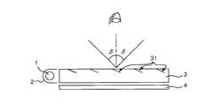
図1は本発明の第1実施形態における照明装置の断面の模式図を示すものである。本発明の第1実施形態における照明装置は、照明装置を上方から観察者が見る角度(以下視野角と呼ぶ)をβとする。
図1において、1は光源であり、例えば、熱陰極管、若しくは冷陰極管などの蛍光灯、あるいは発光ダイオードを線状に配列したもの、あるいは白熱灯、あるいは有機発光材料を線状に形成したものであり、導光体3の側面に配置される。図1において、2はリフレクタであり、光源1を覆うようにして配置され、内面は反射率が高く、拡散性が小さくなるように構成される。例えば、樹脂のシートに銀、若しくはアルミなどの反射率の高い材料を蒸着し、このシートを薄い金属板、あるいは樹脂のシートに接着してリフレクタを構成したものである。光源1が蛍光灯の場合、光源1とリフレクタ2との隙間は、ガラスの屈折率1.5に近い材料で充填するのが望ましい。また、光源1側における導光体3の側面厚みとリフレクタ2の高さは同じであるのが望ましい。その理由は、導光体3は薄いほうが望ましいが、入射効率のため、厚さの下限値がリフレクタ2の高さとなるためである。
図1において、3は透明基板(以下導光体と呼ぶ)であり、石英、ガラス、透明樹脂、例えばアクリル系樹脂、若しくはポリカーボネイトなどを材料とする。導光体3の上面と下面はほぼ平行であり、上面から見ると導光体2はほぼ長方形である。導光体3の側面と上面、側面と下面とは、それぞれ、ほぼ90度の角度をなす。導光体3の上面にはスリット31が形成される。
【0010】
図2にスリット31の部分の詳細図を示す。スリット31は光源1の長手方向にほぼ平行に延在している。スリット31の中は、屈折率の低い材料で満たされており、例えば空気若しくはフッ素系の樹脂で構成される。また、スリット31は、導光体の屈折率をnとし、スリット内部の屈折率をn1とし、スリット31と導光体上面とのなす角をθとし、視野角をβとするとき、
【数11】
θ<sin-1(n1/n)−sin-1{(1/n)sin(β)}
の条件を満たす。
第1実施形態では導光体材料をPMMA(Polymethylmetacrylate)とし、スリット内部を空気とし、視野角を40度としたので、n=1.5、n1=1、β=40より、スリット31と上面とのなす角θは16度とした。また、スリット31の長さ33を50μmとし、スリット31のピッチ32は200μmとした。また、視野角β=30のときはθ=22.34°となる。
図1において、4は反射板である。反射板4は、例えば、書籍や写真などの印刷物や、パーソナルコンピュータなどのOA機器、携帯情報端末、若しくはポータブルビデオテープレコーダーなどの画面表示装置、又は各種モニタに使用される反射型液晶表示装置などを意味する。
【0011】
次に、図3を用いて導光体3内での光の伝搬について説明する。
導光体3に入射された光は、導光体3の屈折率をnとすると、スネルの法則により、放射分布が±sin-1(1/n)の光となる。導光体3の上記した材料のほとんどは、屈折率が1.42以上であるので、放射分布は±44.77度の範囲となる。ところで、導光体3は、上面と下面がほぼ平行であり、導光体3への入射面である側面と上面及び側面と下面は、それぞれ、ほぼ90度の角度をなすので、側面から入射した光が上面あるいは下面に入射すると、入射角の最小値は90−44.77=45.23度となる。屈折率が1.42以上のとき、全反射角は44.77度以下となるので、側面から入射した光は上面及び下面で全反射することになる。
導光体3を伝搬する光のうちスリット31の近傍以外の場所では、導光体3の上面及び下面の平坦部で全反射する。スリット31の部分では、光線の角度によって透過する光線と、全反射する光線とに分かれる。図3に示すように、光線と導光体3の上面とがなす角度をαとすると、
【数12】
α>90−θ−sin-1(n1/n)
のときスリット31を透過し、
【数13】
α<90−θ−sin-1(n1/n)
のときスリット31で全反射する。
【0012】
スリット31を透過した光線は、導光体3の上面の平坦部で全反射し、再び伝搬していく。スリット31で全反射した光線は、導光体3の下面から出射するが、下面への入射角は{90−(2θ+α)}であり、スネルの法則より、
【数14】
90−(2θ+α)<sin-1(1/n)
のとき、導光体3の下面より出射して、反射板4を照明する。
このようにして第1実施形態の照明装置は反射板4を照明するが、光源1から出た光はコリメートされる必要がないので、スリット31にて全反射する率が高く、効率良く反射板4を照明することができる。また、スリット31を透過した光は導光体3を再び伝搬するため、溝筋が見えにくいという効果がある。
【0013】
次に、反射板4を照明した後の反射光の伝搬について図4を用いて説明する。導光体3より照明された光線は反射板4を照明し、反射光を返す。反射光は導光体3に下面より再入射し、スリット31の近傍以外ではそのまま導光体3の上面から出射される。
スリット31の近傍では、反射光の導光体3の下面への入射角をγとすると、
[数15]
θ+sin-1{(1/n)sin(γ)}>sin-1(n1/n)
のときスリット31にて全反射する。このため、反射光41が角度γで導光体3の下面より入射したとき、γ>βのときスリット31で全反射して観察者には到達しないが、γ≦βのときスリット31で透過し観察者まで到達する。
そこで、スリット31で透過する条件は、[数15]より
θ+sin-1{(1/n)sin(γ)}<sin-1(n1/n).....(15A)
でかつγ≦βである。すなわち、
上記式(15A)において、[sin-1{(1/n)sin(γ)}]の項を右辺に移動させると、
θ<sin-1(n1/n)−sin-1{(1/n)sin(γ)}
となり、γ≦βであるから、スリット31の角度θは、
θ<[sin-1(n1/n)−sin-1{(1/n)sin(β)}]≦[sin-1(n1/n)−sin-1{(1/n)sin(γ)}]
となり、
[数16]
θ<sin−1(n1/n)−sin-1{(1/n)sin(β)}
という[数16]が導出される。このことより、反射光は視野角±βの範囲内ではスリット31の部分で全反射しないため、観察者の視野を妨げず、良好な画像を得られる。
【0014】
以上により、本第1実施形態によれば、導光体3の溝筋が見えにくく、反射光の画像が良好に保たれ、照明効率のよい、照明装置を提供することが可能である。また、均一照明が可能であり、光源1から出た光をコリメートする必要がないので、リフレクタ2を小さくすることができ、上記したようにリフレクタ2の高さと導光体3の側面の高さとをほぼ同等にするため、リフレクタ2の高さに応じて導光体3の側面の厚みも小さくすることができる。
なお、第1実施形態では、スリット31は導光体3の上面に配置したが、図11に示すように導光体3の上面と下面との間に、若しくは図12に示すように導光体3の下面に、若しくは図13に示すように導光体3の上面側から下面側に向けて斜めに配置するようにしてもよい。
また、第1実施形態では、導光体3の上面と下面が平行であるが、平行でなくても良い。
また、第1実施形態ではスリット31のピッチ32を等間隔としたが、導光体3の光源1より遠ざかるにつれて小さくすると、光源1から近い所と遠い所とで輝度差が少なくなり、より均一な照明が得られる。また、スリット31の長さ33を、導光体3の光源1より遠ざかるにつれて大きくしても同様の効果が得られる。また、スリット31の角度θを光源1より遠ざかるにつれて大きくしても同様の効果が得られる。
【0015】
以下、本発明の第2実施形態による照明装置について、図5を用いて説明する。
図5は、本発明の第2実施形態における照明装置の断面の模式図である。本発明の第2実施形態における照明装置は、視野角をβとする。
図5において、光源1及びリフレクタ2は第1実施形態と同様である。
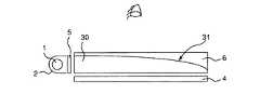
図5において、30は第1の透明基板の一例としての導光体であり、6は導光体30の上に配置された第2の透明基板の一例としての補償板である。5は光源1と導光体30との間に配置されたコリメータであり、光源1から出射された光を平行化する。導光体30の上面の階段状の斜面131の角度をθとし、導光体30の屈折率をnとし、導光体30と補償板6の間の材料の屈折率をn2として、コリメータ5の出射特性は、±sin-1[n*sin{90−θ−sin-1(n2/n)}]以内である。
例えば、β=40、n=1.5、n2=1のとき、θ=16°であり、コリメータ5の出射特性は、±52.13°である。また、β=30、n=1.5、n2=1のときは、θ=22.34であり、コリメータ5の出射特性は±40.85°である。
コリメータ5の構造は、例えば、上記出射特性を満たす、平凸のシリンドリカルレンズで実現可能である。また、コリメータ5は回折格子であっても良い。また、照明装置の視野角βが大きい場合は、コリメータ5の出射特性角度が大きいのでコリメータ5がなくても良い。
【0016】
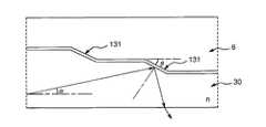
導光体30は、石英、ガラス、透明樹脂、例えばアクリル系樹脂、若しくはポリカーボネイトなどを材料とする。図6に導光体30の詳細な図を示す。導光体30は下面は平面であり、上面は階段状の斜面131が所定の間隔をおいて複数本配置されている。各斜面131は光源1の長手方向にほぼ平行である。
斜面131の角度をθとし、導光体30の材質の屈折率をnとし、導光体30と補償板6との間の材料の屈折率をn2とし、視野角をβとするとき、斜面131の角度θは、
【数17】
θ<sin-1(n2/n)−sin-1{(1/n)sin(β)}
である。斜面131のピッチ32は、導光体30の光源1より遠ざかるにつれて小さくすると良い。また斜面131の長さ33を、導光体30の光源1より遠ざかるにつれて大きくしても良い。また、斜面131の角度θを光源1より遠ざかるにつれて大きくしても良い。また、導光体30は上面から見るとほぼ長方形である。
補償板6は、石英、ガラス、透明樹脂、例えばアクリル系樹脂、若しくはポリカーボネイトなどを材料とする。補償板6は、下面は階段状の斜面61が前記導光体30の上面の斜面131と同形状で配置され、上面は平面である。導光体30の上面と補償板6の下面は所定の間隔をもって配置されている。
図5において、4は反射板である。反射板4は例えば、書籍や写真などの印刷物や、パーソナルコンピュータなどのOA機器、携帯情報端末、若しくはポータブルビデオテープレコーダーなどの画面表示装置、各種モニタに使用される反射型液晶表示装置などである。
【0017】
次に、図7を用いて第2の実施形態の導光体30内での光の伝搬について説明する。導光体30に入射した光は、導光体30の斜面131の近傍以外の場所では導光体30の上面または下面の平坦部において全反射しながら伝搬していく。導光体30の斜面131の近傍では、光線の角度によって透過する光線と、全反射する光線とに分かれる。導光体30の屈折率をnとし、導光体30と補償板6の間の材料の屈折率をn2とし、導光体30の下面と光線がなす角度をαとし、導光体30の斜面131の角度をθとすると、
【数18】
α>90−θ−sin-1(n2/n)
のとき導光体30の斜面131を透過し、
【数19】
α<90−θ−sin-1(n2/n)
のとき導光体30の斜面131で全反射する。
【0018】
導光体30の斜面131を透過した光線は、補償板6の光源1とは反対側に到達した後に反射するため、観察者側に出射する可能性が高く、照明効率を劣化させる。しかし、光源1のコリメータ5の出射特性が、±sin-1[n*sin{90−θ−sin-1(n2/n)}]以内であるため、導光体30へ入射される光線は、±{90−θ−sin-1(n2/n)}以内となり、したがって(数19)の式を満たすため、ほとんどの光線は導光体30の斜面131で全反射し、反射板4を照明する。
よって、光源1から出射された光は効率良く反射板4を表示することが可能である。また、このように効率良く反射板4を照明するため、導光体30の斜面131より観察者側に透過する光線が少ないので、溝筋が見えにくいという効果がある。
【0019】
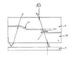
次に、反射板4を照明した後の反射光の伝搬について図8を用いて説明する。導光体30より照明された光線は反射板4を照明し、反射光を返す。反射光は導光体30に下面より再入射し、導光体30の斜面131の近傍以外ではそのまま上面から出射される。
導光体30の斜面131の近傍では、反射光の導光体30の下面への入射角をγとすると、
【数20】
θ+sin-1{(1/n)sin(γ)}>sin-1(n2/n)
のとき導光体30の斜面131にて全反射する。このため、反射光41が角度γで導光体の下面より入射したとき、γ>βのとき斜面131で全反射して観察者には到達しないが、γ≦βのとき斜面131を透過して観察者まで到達する。
このことと、導光体30の斜面131の角度θが、
【数21】
θ<sin-1(n2/n)−sin-1{(1/n)sin(β)}
であることより、反射光は視野角±βの範囲内では導光体30の斜面131の部分で全反射しないため、観察者の視野を妨げず、良好な画像を得られる。
【0020】
以上により第2の実施形態によれば、導光体30の溝筋が見えにくく、反射光の画像が良好に保たれ、照明効率のよい、照明装置を提供することが可能である。
なお、第2実施形態では、階段状の溝としたが図14に示すような任意の曲線でもよい。また、第2実施形態では斜面131のピッチ32を等間隔としたが、導光体30の光源1より遠ざかるにつれて小さくすると、光源1から近い所と遠い所とで輝度差が少なく、均一な照明が得られる。また、斜面131の長さ33を、導光体30の光源1より遠ざかるにつれて大きくしても同様の効果が得られる。また、斜面131の角度θを光源1より遠ざかるにつれて大きくしても同様の効果が得られる。
また、図17のように、補償板6の上面と導光体30の下面が平行でなくても同様の効果が得られる。
また、図18のように、補償板6の上面が曲面であっても同様の効果が得られる。
【0021】
以下、本発明の第3実施形態による照明装置について説明する。
本発明の第3実施形態の構造は第2実施形態とほぼ同一であり、コリメータ5の構造のみ異なる。
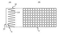
図9を用いて第3実施形態のコリメータ5の構造を説明する。コリメータ5の光線入射面51は平面である。コリメータ5の出射面52は、頂角2δの円錐形の凹部が複数設けられた構造となっている。
導光体30の屈折率をnとし、導光体30と補償板6を貼り合わせている材料の屈折率をn2とし、コリメータ5の屈折率をn3としたとき、δは
【数22】
sin-1[n*sin{90−θ−sin-1(n2/n)}]=90−δ−sin-1[n3*sin{90−δ−sin-1(1/n3)}]
を満たす値である。
【0022】
次に、図10を用いて、コリメータ5の動作を説明する。光源1から発した光線がコリメータ5の入射面51から入射すると、その放射分布は±sin-1(1/n3)である。よって、コリメータ5の出射側の斜面52に入射される光線角度は幾何的に求まり、入射角最小値iminは、
【数23】
imin=90−δ−sin-1(1/n3)
であり、入射角最大値imaxは、
【数24】
imax=90
である。
また、コリメータ5から出射される光線角度はスネルの法則より求まり、出射側の斜面52に対する出射角度最小値ominは、
【数25】
omin=sin-1{n3*sin(imin)}
であり、出射角最大値omaxは、
【数26】
omax=90
である。
【0023】
出射側の斜面52はδだけ光軸に対して傾いているので、出射角最大値ωmaxは、
【数27】
ωmax=90−δ−omin
であり、また出射角最小値ωminは、
【数28】
ωmin=−δ
である。すなわち、
【数29】
ωmax=90−δ−sin-1[n3*sin{90−δ−sin-1(1/n3)}]
【数30】
ωmin=−δ
である。
【0024】
ところで、導光体30の斜面131の角度をθ、導光体30と補償板6との間にある材料の屈折率をn2としたとき、必要なコリメータ5の出射特性は±sin-1[n*sin{90−θ−sin-1(n2/n)}]以内である。δは、sin-1[n*sin{90−θ−sin-1(n2/n)}]=90−δ−sin-1[n3*sin{90−δ−sin-1(1/n3)}]を満たす値としているので、ωmax=(コリメータ5の出射特性)となっており、所望の出射特性を満たしている。
例えば、視野角β=30、n=1.5、n2=1、n3=1.5としたときにθ=22.4となり、必要な出射特性は40.85°であり、δ=46.2°としたときの出射角度は、ωmax=+40.81°、ωmin=−46.2°となり、所望のコリメータ5の出射特性が得られる。また、δ=sin-1[n*sin{90−θ−sin-1(n2/n)}]を満たす値とすると、上記の例でδ=40.85°、ωmax=+38.10°、ωmin=−40.85°となるので、所望のコリメータ5の出射特性が得られる。また、上記条件でδは40.85°以上46.2°以下の任意の値としても良い。
【0025】
以上のように第3実施形態を用いれば、導光体30に必要な出射特性を満足するコリメータ5を実現でき、第2実施形態と同様の効果を得ることができる。
なお、第3実施形態ではコリメータ5の出射面52の形状を頂角2δの円錐形の凹部としたが、頂角2δの円錐形の突起でもよい。また、円錐形の代わりに断面の頂角2δの多角錘でもよい。また、図15(A),(B)に示すような、頂角2δの平行な溝であっても良い。
【0026】
【発明の効果】
以上のように、本発明の一態様によれば、平板状の導光体の側面に光源例えば線状光源を配置し、導光体の内部にスリットを光源とほぼ平行に延在するように配置することによって、前記導光体の内部を伝搬する光の大部分を、導光体に形成されたスリットでの全反射によって導光体より射出し、被照明物の例としての反射板を照射することができ、またスリットにおいて全反射せず、透過する光は再び導光体内部を伝搬するため、溝筋が見えにくく、また反射板からの反射光は歪みがなく観察者側へ透過するので、反射板の良好な画質を保つことが可能である。また、光源から出射される光線をコリメートする必要がないため、反射表示用照明装置を小型化でき、また全ての光線がスリットでの全反射によって導光体より射出されるので照明効率がよい。また、スリットを所定の角度で配置することにより、観察者の視野内でスリット部とスリット部以外での輝度差が少なく、反射光の良好な画質を保つことが可能である。
【0027】
また、本発明の別の態様によれば、第1の透明基板の例としての導光体の側面に光源例えば線状光源を配置し、光源から出射される光をコリメータによって平行化し、前記導光体の形状を下面が平面で上面が階段状の斜面が所定の角度で設けられたものとし、上面が平面で下面が前記導光体と同形状の溝が設けられた第2の透明基板の例としての補償板を前記導光体に貼り合わせることにより、前記導光体の内部を伝搬する光の大部分を前記導光体の階段状の斜面での全反射によって前記導光体より射出し、被照明物の例としての反射板を照射することができる。また、補償板があるため反射板からの反射光は歪みがなく観察者側へ透過するので、前記反射板の良好な画質を保つことが可能である。また、光源から出射される光は、前記コリメータによって所定の角度に平行化されるので前記導光体から前記補償板へ透過せず、反射板を効率よく照明することが可能であり、また溝筋が見えにくい。また、階段状の斜面を所定の角度にすることによって、観察者の視野内で階段状の斜面部と斜面部以外での輝度差が少なく、反射光の良好な画質を保つことが可能である。
また、本発明のさらに別の態様によれば、導光体に必要な出射特性を満足するコリメータを実現でき、前記した態様の効果をも得ることができる。
【図面の簡単な説明】
【図1】 本発明の第1実施形態における照明装置の断面の模式図
【図2】 第1実施形態におけるスリットの配置を示す模式図
【図3】 第1実施形態における導光体内での光の伝搬について説明するための図
【図4】 第1実施形態における導光体内での反射光の伝搬について説明するための図
【図5】 本発明の第2実施形態における照明装置の断面の模式図
【図6】 第2実施形態における導光体内での光の伝搬について説明するための図
【図7】 第2実施形態における導光体内での光の伝搬について説明するための図
【図8】 第2実施形態における導光体内での反射光の伝搬について説明するための図
【図9】 (A),(B)は第2実施形態におけるコリメータの概略断面側面図及び平面図
【図10】 第2実施形態におけるコリメータの動作を説明するための図
【図11】 本発明の第1実施形態における照明装置の一変形例の断面の模式図
【図12】 本発明の第1実施形態における照明装置の別の変形例の断面の模式図
【図13】 本発明の第1実施形態における照明装置のさらに別の変形例の断面の模式図
【図14】 本発明の第2実施形態における照明装置の一例の断面の模式図
【図15】 (A),(B)は本発明の第3実施形態における照明装置のコリメータの概略断面側面図及び平面図
【図16】 従来の照明装置の断面の模式図
【図17】 本発明の第2実施形態における照明装置の一変形例の断面の模式図
【図18】 本発明の第2実施形態における照明装置の別の変形例の断面の模式図
【符号の説明】
1 光源
2 リフレクタ
3 導光体
4 反射板
5 コリメータ
6 補償板
30 導光体
31 スリット
32 スリットのピッチ
33 スリットの長さ
41 反射光
51 コリメータの入射面
52 コリメータの出射面
131 斜面[0001]
BACKGROUND OF THE INVENTION
The present invention is used for printed materials such as books and photographs, OA devices such as personal computers, screen display devices such as portable information terminals and portable video tape recorders, or reflective liquid crystal display devices used for various monitors. BeFor reflection displayThe present invention relates to a lighting device.
[0002]
[Prior art]
In recent years, personal computers, portable information terminals, video tape recorders, and the like have become smaller and more portable, and reduction of power consumption of image display devices has become an important issue. For this reason, many image display devices use a reflective liquid crystal display device.
The reflective liquid crystal display element obtains screen brightness by reflecting external light such as sunlight and room light. However, sufficient brightness cannot be obtained on the screen where there is little external light. In view of this, some reflective liquid crystal display devices with an illumination device capable of displaying a screen even in a place where external light is insufficient have been invented.
An example of the illuminating device attached to a reflection type liquid crystal display element is shown. FIG. 16 is a schematic diagram of a cross-sectional view of a conventional lighting device. As shown in FIG. 16, the conventional illumination device includes a
[0003]
[Problems to be solved by the invention]
However, in the conventional illumination device, when the light beam transmitted from the
Then, this invention makes it a subject to solve such a problem, a groove line is hard to see, the image of reflected light is kept favorable, and illumination efficiency is good.For reflection displayAn object is to provide a lighting device.
[0004]
[Means for Solving the Problem and Action]
In order to achieve the above object, the present invention is configured as follows.
According to the first aspect of the present invention, a light source and the light sourceIt is the surface where light fromsideAnd upper and lower surfaces parallel to each otherA transparent substrate,
The transparent substrate has a refractive index different from that of the transparent substrate.Groove with material insideWith being placed,PreviousThe refractive index of the transparent substrate is n,In the grooveThe refractive index of the material is n1age,For reflection displayWhen the viewing angle of the lighting device is β,
The acute angle θ out of the angle formed by the groove and the upper surface of the transparent substrate is
(Equation 5)
θ <sin-1(N1/ N) -sin-1{(1 / n) sin (β)}<90 °
Characterized by satisfying the conditions ofFor reflection displayA lighting device is provided.
[0005]
According to the second aspect of the present invention, at least a light source and the light sourceThe surface where light from is incidentThe sideToA transparent first substrate and an upper surface of the first substrate;directionAnd a transparent second substrate disposed on the substrate,
Said first substrateofBottomIsA plane, saidOf the first substrateTopInStepped slopeIs arrangedPlaced,
Said second substrateofThe lower surface has a stepped slope arranged in the same shape as the slope of the upper surface of the first substrate.,PreviousPlace a collimator at the exit of the light source,
The refractive index of the first substrate is n, and the first substrate and the second substratePlaced betweenThe refractive index of the material is n2age,For reflection displayWhen the viewing angle of the lighting device is β,
An acute angle θ among the angles of the slopes of the upper surface of the first substrate and the lower surface of the second substrate is:
(Equation 6)
θ <sin-1(N2/ N) -sin-1{(1 / n) sin (β)}<90 °
To meet the requirements of
The pitch of the slope becomes smaller as the distance from the light source of the first substrate increases.BecomeIn addition, the slope length is set to the first substrate.Light ofBigger as you move away from the sourceBecomeIt is characterized byFor reflection displayA lighting device is provided.
[0006]
According to the third aspect of the present invention, in the second aspect, the light beam emission angle of the collimator disposed at the light source outlet is ± sin.-1[N * sin {90-θ-sin-1(N2/ N)}].For reflection displayA lighting device is provided.
According to a fourth aspect of the present invention, in the second or third aspect, the collimator disposed at the exit of the light source has a plane of light incident surface, and the refractive index of the first substrate is n, The refractive index of the material for bonding the first substrate and the second substrate is n2And the refractive index of the collimator is n3And an angle δ which is a half of the apex angle of the convex portion constituting the conical concave portion of the exit surface of the collimator is
(Equation 7)
sin-1[N * sin {90-θ-sin-1(N2/ N)}] = 90−δ−sin-1[NThree* Sin {90-δ-sin-1(1 / nThree]}]
When the value satisfies the above, a plurality of inclined surfaces having an angle + δ or an angle −δ are arranged on the exit surface of the collimator.For reflection displayA lighting device is provided.
According to a fifth aspect of the present invention, in the second or third aspect, the collimator arranged at the exit of the light source has a plane light incident surface, and the refractive index of the first substrate is n, The refractive index of the material for bonding the first substrate and the second substrate is n2And the refractive index of the collimator is n3And an angle δ which is a half of the apex angle of the convex portion constituting the conical concave portion of the exit surface of the collimator is
(Equation 8)
δ = sin-1[N * sin {90-θ-sin-1(N2/ N)}]
When the value satisfies the above, a plurality of inclined surfaces having an angle + δ or an angle −δ are arranged on the exit surface of the collimator.For reflection displayA lighting device is provided.
[0007]
According to the first to third aspects of the present invention, the light emitted from the light source enters the transparent substrate and propagates while repeating total reflection in the transparent substrate. At this time, the light rays are divided into those that are totally reflected by the slits inside the transparent substrate and those that are transmitted. Since the angle of the totally reflected light beam is changed and becomes smaller than the total reflection angle, it is emitted to the lower surface side of the transparent substrate. Further, since the transmitted light is totally reflected on the upper surface of the transparent substrate and then propagates through the transparent substrate, the slit streaks on the transparent substrate are difficult to see. In addition, since a collimator that has been conventionally required to transmit the slit and make the groove lines difficult to see becomes unnecessary, almost all light rays are emitted to the lower side of the transparent substrate, so that the illumination efficiency is good.
The light emitted from the lower surface of the transparent substrate irradiates the object to be illuminated, and the reflected light from the object to be illuminated is incident again on the transparent substrate.
[Equation 9]
θ <sin-1(N1/ N) -sin-1{(1 / n) sin (β)}
Therefore, a good image can be displayed without being influenced by the viewing angle.
In this way, it is possible to provide an illuminating device in which the groove is difficult to see and the illumination efficiency is good.
[0008]
According to the fourth to ninth aspects of the present invention, the light beam emitted from the light source is collimated by the collimator and introduced into the first substrate. The light incident on the first substrate is totally reflected on the slope of the first substrate, and the light beam angle is smaller than the total reflection angle, so that it is emitted to the lower surface side.
Further, the light emitted from the lower surface of the first substrate illuminates the object to be illuminated, and the reflected light from the object to be illuminated is incident on the first substrate again, but because there is the second substrate, There is no image distortion,
[Expression 10]
θ <sin-1(N1/ N) -sin-1{(1 / n) sin (β)}
If so, a good image can be displayed without being influenced by the viewing angle.
Also, the collimator's light emission angle is ± {90-θ-sin.-1(N1/ N)}, all the light beams emitted from the light source are totally reflected by the slope of the first substrate and can illuminate the object to be illuminated, and the illumination efficiency is good.
In this manner, it is possible to provide an illumination device that is less likely to see the groove stripes, maintains the image quality of the reflected light, and has high illumination efficiency.
[0009]
DETAILED DESCRIPTION OF THE INVENTION
Hereinafter, a lighting apparatus according to a first embodiment of the present invention will be described with reference to the drawings.
FIG. 1 shows a schematic diagram of a cross section of a lighting device according to a first embodiment of the present invention. In the illuminating device according to the first embodiment of the present invention, an angle at which an observer views the illuminating device from above (hereinafter referred to as a viewing angle) is β.
In FIG. 1,
In FIG. 1,
[0010]
FIG. 2 shows a detailed view of the
## EQU11 ##
θ <sin-1(N1/ N) -sin-1{(1 / n) sin (β)}
Satisfy the condition of
In the first embodiment, since the light guide material is PMMA (Polymethylmetacrylate), the inside of the slit is air, and the viewing angle is 40 degrees, n = 1.5, n1= 1 and β = 40, the angle θ between the
In FIG. 1, 4 is a reflecting plate. The reflector 4 is, for example, a printed material such as a book or a photo, an OA device such as a personal computer, a screen display device such as a portable information terminal or a portable video tape recorder, or a reflective liquid crystal display device used for various monitors. Means.
[0011]
Next, the propagation of light in the
The light incident on the
The light propagating through the
[Expression 12]
α> 90−θ−sin-1(N1/ N)
Is transmitted through the
[Formula 13]
α <90−θ−sin-1(N1/ N)
At this time, the light is totally reflected by the
[0012]
The light beam transmitted through the
[Expression 14]
90− (2θ + α) <sin-1(1 / n)
At this time, the light is emitted from the lower surface of the
Thus, although the illuminating device of 1st Embodiment illuminates the reflecting plate 4, since the light emitted from the
[0013]
Next, propagation of reflected light after illuminating the reflector 4FIG.Will be described. The light beam illuminated from the
In the vicinity of the
[Equation 15]
θ + sin-1{(1 / n) sin (γ)}> sin-1(N1/ N)
At this time, the light is totally reflected by the
Therefore, the condition for transmission through the
θ + sin-1{(1 / n) sin (γ)} <sin-1(N1/ N).....(15A)
And γ ≦ β. That is,
In the above formula (15A), [sin-1When the term {(1 / n) sin (γ)}] is moved to the right side,
θ <sin-1(N1/ N) -sin-1{(1 / n) sin (γ)}
Since γ ≦ β, the angle θ of the
θ <[sin-1(N1/ N) -sin-1{(1 / n) sin (β)}] ≦ [sin-1(N1/ N) -sin-1{(1 / n) sin (γ)}]
And
[Equation 16]
θ <sin−1(N1/ N) -sin-1{(1 / n) sin (β)}
[Equation 16] is derived. thisThus, since the reflected light is not totally reflected by the
[0014]
As described above, according to the first embodiment, it is possible to provide an illuminating device in which the groove of the
In the first embodiment, the
Moreover, in 1st Embodiment, although the upper surface and lower surface of the
Further, in the first embodiment, the
[0015]
Hereinafter, a lighting apparatus according to a second embodiment of the present invention will be described with reference to FIG.
FIG. 5 is a schematic cross-sectional view of a lighting device according to the second embodiment of the present invention. In the illumination device according to the second embodiment of the present invention, the viewing angle is β.
In FIG. 5, the
In FIG. 5, 30 is a light guide as an example of a first transparent substrate, and 6 is a compensator as an example of a second transparent substrate disposed on the
For example, β = 40, n = 1.5, n2When = 1, θ = 16 °, and the output characteristics of the
The structure of the
[0016]
The
The angle of the
[Expression 17]
θ <sin-1(N2/ N) -sin-1{(1 / n) sin (β)}
It is. The
The
In FIG. 5, 4 is a reflector. The reflector 4 is, for example, a printed material such as a book or a photo, an OA device such as a personal computer, a screen display device such as a portable information terminal or a portable video tape recorder, a reflective liquid crystal display device used for various monitors, and the like. .
[0017]
Next, the propagation of light in the
[Expression 18]
α> 90−θ−sin-1(N2/ N)
Is transmitted through the
[Equation 19]
α <90−θ−sin-1(N2/ N)
At this time, the light is totally reflected by the
[0018]
The light beam that has passed through the
Therefore, the light emitted from the
[0019]
Next, propagation of reflected light after illuminating the reflector 4 will be described with reference to FIG. The light beam illuminated from the
In the vicinity of the
[Expression 20]
θ + sin-1{(1 / n) sin (γ)}> sin-1(N2/ N)
At this time, the light is totally reflected by the
This and the angle θ of the
[Expression 21]
θ <sin-1(N2/ N) -sin-1{(1 / n) sin (β)}
Therefore, the reflected light is not totally reflected by the
[0020]
As described above, according to the second embodiment, it is possible to provide an illuminating device in which the groove of the
In the second embodiment, a step-like groove is used, but an arbitrary curve as shown in FIG. 14 may be used. Further, in the second embodiment, the
Also, as shown in FIG. 17, the same effect can be obtained even if the upper surface of the
Further, the same effect can be obtained even when the upper surface of the
[0021]
Hereinafter, a lighting device according to a third embodiment of the present invention will be described.
The structure of the third embodiment of the present invention is almost the same as that of the second embodiment, and only the structure of the
The structure of the
The refractive index of the
[Expression 22]
sin-1[N * sin {90-θ-sin-1(N2/ N)}] = 90−δ−sin-1[NThree* Sin {90-δ-sin-1(1 / nThree]}]
It is a value that satisfies
[0022]
Next, the operation of the
[Expression 23]
imin= 90-δ-sin-1(1 / nThree)
And the maximum angle of incidence imaxIs
[Expression 24]
imax= 90
It is.
Further, the light ray angle emitted from the
[Expression 25]
omin= Sin-1{NThree* Sin (imin)}
And the maximum output angle omaxIs
[Equation 26]
omax= 90
It is.
[0023]
Since the outgoing-
[Expression 27]
ωmax= 90−δ−omin
And the output angle minimum value ωminIs
[Expression 28]
ωmin= −δ
It is. That is,
[Expression 29]
ωmax= 90-δ-sin-1[NThree* Sin {90-δ-sin-1(1 / nThree]}]
[30]
ωmin= −δ
It is.
[0024]
By the way, the angle of the
For example, viewing angle β = 30, n = 1.5, n2= 1, nThreeWhen θ = 1.5, θ = 22.4, and the required output characteristic is 40.85 °. When δ = 46.2 °, the output angle is ωmax= + 40.81 °, ωmin= −46.2 °, and the desired output characteristics of the
[0025]
As described above, when the third embodiment is used, the
In the third embodiment, the shape of the
[0026]
【The invention's effect】
As described above, according to one aspect of the present invention, a light source, for example, a linear light source is disposed on a side surface of a flat light guide, and a slit extends substantially parallel to the light source inside the light guide. By disposing, a majority of the light propagating inside the light guide is emitted from the light guide by total reflection at the slit formed in the light guide, and a reflector as an example of an object to be illuminated is provided. Irradiates, and does not totally reflect in the slit, and the transmitted light propagates through the light guide again, so it is difficult to see the groove streaks, and the reflected light from the reflector plate is transmitted without distortion to the viewer side Therefore, it is possible to maintain a good image quality of the reflector. In addition, since it is not necessary to collimate the light emitted from the light source,For reflection displayThe illumination device can be miniaturized, and all the light rays are emitted from the light guide through total reflection at the slit, so that the illumination efficiency is good. In addition, by arranging the slits at a predetermined angle, it is possible to maintain a good image quality of the reflected light by reducing the luminance difference between the slit portion and the portion other than the slit portion within the observer's visual field.
[0027]
According to another aspect of the present invention, a light source, for example, a linear light source is disposed on a side surface of a light guide as an example of the first transparent substrate, and the light emitted from the light source is collimated by a collimator so that the light is guided. A second transparent substrate in which the shape of the light body is such that the lower surface is flat and the upper surface is a stepped slope at a predetermined angle, and the upper surface is flat and the lower surface is provided with grooves of the same shape as the light guide. By adhering a compensation plate as an example of the light guide to the light guide, most of the light propagating inside the light guide is reflected from the light guide by total reflection on the stepped slope of the light guide. It can inject | emits and can irradiate the reflecting plate as an example of a to-be-illuminated object. In addition, since there is a compensation plate, the reflected light from the reflecting plate is transmitted without distortion to the viewer side, so that the image quality of the reflecting plate can be maintained. Further, since the light emitted from the light source is collimated at a predetermined angle by the collimator, the light is not transmitted from the light guide to the compensation plate, and the reflector can be efficiently illuminated. It is difficult to see the streaks. In addition, by setting the stepped slope to a predetermined angle, there is little difference in brightness between the stepped slope and the sloped part within the observer's field of view, and good image quality of reflected light can be maintained. .
Further, according to still another aspect of the present invention, a collimator that satisfies the emission characteristics necessary for the light guide can be realized, and the effects of the aspect described above can also be obtained.
[Brief description of the drawings]
FIG. 1 is a schematic cross-sectional view of a lighting device according to a first embodiment of the present invention.
FIG. 2 is a schematic diagram showing the arrangement of slits in the first embodiment.
FIG. 3 is a diagram for explaining light propagation in the light guide in the first embodiment.
FIG. 4 is a diagram for explaining propagation of reflected light in the light guide in the first embodiment.
FIG. 5 is a schematic cross-sectional view of a lighting device according to a second embodiment of the present invention.
FIG. 6 is a diagram for explaining light propagation in the light guide in the second embodiment.
FIG. 7 is a view for explaining light propagation in the light guide in the second embodiment.
FIG. 8 is a view for explaining propagation of reflected light in the light guide in the second embodiment.
9A and 9B are a schematic cross-sectional side view and a plan view of a collimator according to a second embodiment.
FIG. 10 is a diagram for explaining the operation of the collimator in the second embodiment;
FIG. 11 is a schematic cross-sectional view of a modification of the lighting device according to the first embodiment of the present invention.
FIG. 12 is a schematic cross-sectional view of another modification of the lighting device according to the first embodiment of the present invention.
FIG. 13 is a schematic cross-sectional view of still another modification of the lighting device according to the first embodiment of the present invention.
FIG. 14 is a schematic cross-sectional view of an example of a lighting device according to a second embodiment of the present invention.
FIGS. 15A and 15B are a schematic sectional side view and a plan view of a collimator of a lighting device according to a third embodiment of the present invention.
FIG. 16 is a schematic cross-sectional view of a conventional lighting device.
FIG. 17 is a schematic cross-sectional view of a modification of the lighting device according to the second embodiment of the present invention.
FIG. 18 is a schematic cross-sectional view of another modification of the lighting device according to the second embodiment of the present invention.
[Explanation of symbols]
1 Light source
2 Reflector
3 Light guide
4 reflectors
5 Collimator
6 Compensation plate
30 Light guide
31 slit
32 Pitch of slit
33 Slit length
41 Reflected light
51 Collimator entrance surface
52 Output surface of collimator
131 slope
Claims (5)
Translated fromJapanese前記透明基板には、前記透明基板の屈折率とは異なる屈折率を有する材料を内部に有する溝(31)が配置されるとともに、前記透明基板(3)の屈折率をnとし、前記溝内の前記材料の屈折率をn1とし、反射表示用照明装置の視野角をβとするとき、
前記溝と前記透明基板の上面とのなす角のうちの鋭角θが、
(数1)
θ<sin−1(n1/n)−sin−1{(1/n)sin(β)}<90°
の条件を満たすようにしたことを特徴とする反射表示用照明装置。A light source (1), anda transparent substrate (3)having sidesurfaces that are surfaces onwhich lightfrom the light sourceis incidentand upper and lower surfaces parallel to each other ,
The transparent substrate, witha groove (31)is placedwith a material having a refractive index different from the refractive index of the transparent substratetherein, apre-Symbol refractive index of the transparent substrate (3) is n, theWhen the refractive index of the materialin the groove is n1 and the viewing angle of thereflective display lighting device is β,
The acute angle θ out of the angle formed by the groove and the upper surface of the transparent substrate is
(Equation 1)
θ <sin−1 (n1 / n) −sin−1 {(1 / n) sin (β)}<90 °
An illumination devicefor reflection display characterized by satisfying the above condition.
前記第1の基板の下面は平面であり、前記第1の基板の上面には階段状の斜面(131)が配置され、
前記第2の基板の下面は階段状の斜面が前記第1の基板の前記上面の前記斜面と同形状で配置され、前記光源の出射口にコリメータ(5)を配置し、
前記第1の基板の屈折率をnとし、前記第1の基板と前記第2の基板の間に配置された材料の屈折率をn2とし、反射表示用照明装置の視野角をβとするとき、
前記第1の基板の前記上面および前記第2の基板の前記下面の斜面の角度のうちの鋭角θが、
(数2)
θ<sin−1(n2/n)−sin−1{(1/n)sin(β)}<90°
の条件を満たすようにするとともに、
上記斜面(131)のピッチ(32)は、上記第1の基板の光源より遠ざかるにつれて小さくなるとともに、上記斜面長さ(33)を、上記第1の基板の光源より遠ざかるにつれて大きくなるようにしたことを特徴とする反射表示用照明装置。At least a light source (1),a transparent first substrate (30) havinga surface on which lightfrom the light sourceis incident as a side surface ,and a transparent second substrate disposed in the upper surfacedirection of the first substrate ( 6)
The lower surfaceof the first substrateis a plane, stepped slope (131)is placedon the upper surfaceof saidfirst substrate,
The lower surfaceof the second substrate stepped slope which are arranged in the inclined surfaces having the same shape of the upper surface of the firstsubstrate, placing the collimator (5) to the exit of theprevious SL source,
The refractive index of the first substrate is n, the refractive index of thematerial disposed between the second substrate and the first substrate and n2, the viewing angle of thereflective display illumination device and β When
An acute angle θ among the angles of the slopes of the upper surface of the first substrate and the lower surface of the second substrate is:
(Equation 2)
θ <sin−1 (n2 / n) −sin−1 {(1 / n) sin (β)}<90 °
To meet the requirements of
The pitch of the inclined surface (131) (32), together withsmaller with increasing distance from the light source of the first substrate, the inclined surface length (33), tobe larger with distance from thelight sourceof said first substrate A lighting devicefor reflection display, which is characterized by the above.
(数3)
sin−1[n*sin{90−θ−sin−1(n2/n)}]=90−δ−sin−1[n3*sin{90−δ−sin−1(1/n3)}]
を満たす値であるとしたとき、前記コリメータの出射面が角度+δまたは角度−δの斜面が複数個配置されている請求項2又は3に記載の反射表示用照明装置。The collimator (5) disposed at the light emission port of the light source has a flat light incident surface, the refractive index of the first substrate is n, and the first substrate and the second substrate are bonded together. The refractive index of the material is n2 , the refractive index of the collimator is n3, and the angle δ which is half the apex angle of the convex portion constituting the conical concave portion of the exit surface (52) of the collimator is (Expression 3)
sin−1 [n * sin {90−θ−sin−1 (n2 / n)}] = 90−δ−sin−1 [n3 * sin {90−δ−sin−1 (1 / n3 ) }]
4. Thereflection display illumination device according to claim 2, wherein a plurality of inclined surfaces having an angle of + δ or an angle of −δ are arranged on the exit surface of the collimator when the value satisfies the following condition.
(数4)
δ=sin−1[n*sin{90−θ−sin−1(n2/n)}]
を満たす値であるとしたとき、前記コリメータの出射面が角度+δまたは角度−δの斜面が複数個配置されている請求項2又は3に記載の反射表示用照明装置。The collimator (5) disposed at the light emission port of the light source has a flat light incident surface, the refractive index of the first substrate is n, and the first substrate and the second substrate are bonded together. The refractive index of the material is n2 , the refractive index of the collimator is n3, and the angle δ which is half the apex angle of the convex portion constituting the conical concave portion of the exit surface (52) of the collimator is (Expression 4)
δ = sin−1 [n * sin {90−θ−sin−1 (n2 / n)}]
4. Thereflection display illumination device according to claim 2, wherein a plurality of inclined surfaces having an angle of + δ or an angle of −δ are arranged on the exit surface of the collimator when the value satisfies the following condition.
Priority Applications (4)
| Application Number | Priority Date | Filing Date | Title |
|---|---|---|---|
| JP12234397AJP3703250B2 (en) | 1997-05-13 | 1997-05-13 | Reflective display lighting device |
| EP98108588AEP0879991A3 (en) | 1997-05-13 | 1998-05-12 | Illuminating system |
| KR1019980017136AKR100315198B1 (en) | 1997-05-13 | 1998-05-13 | Illuminating system |
| US09/769,497US6379017B2 (en) | 1997-05-13 | 2001-01-26 | Illuminating system |
Applications Claiming Priority (1)
| Application Number | Priority Date | Filing Date | Title |
|---|---|---|---|
| JP12234397AJP3703250B2 (en) | 1997-05-13 | 1997-05-13 | Reflective display lighting device |
Publications (2)
| Publication Number | Publication Date |
|---|---|
| JPH10311915A JPH10311915A (en) | 1998-11-24 |
| JP3703250B2true JP3703250B2 (en) | 2005-10-05 |
Family
ID=14833616
Family Applications (1)
| Application Number | Title | Priority Date | Filing Date |
|---|---|---|---|
| JP12234397AExpired - Fee RelatedJP3703250B2 (en) | 1997-05-13 | 1997-05-13 | Reflective display lighting device |
Country Status (1)
| Country | Link |
|---|---|
| JP (1) | JP3703250B2 (en) |
Families Citing this family (13)
| Publication number | Priority date | Publication date | Assignee | Title |
|---|---|---|---|---|
| JP4113633B2 (en)* | 1999-04-20 | 2008-07-09 | 日東電工株式会社 | Liquid crystal display |
| JP4462512B2 (en)* | 1999-04-26 | 2010-05-12 | 日東電工株式会社 | Liquid crystal display |
| JP2000330107A (en)* | 1999-05-24 | 2000-11-30 | Nitto Denko Corp | Liquid crystal display |
| JP4006918B2 (en) | 2000-02-28 | 2007-11-14 | オムロン株式会社 | Surface light source device and manufacturing method thereof |
| US6592233B1 (en)* | 2000-10-03 | 2003-07-15 | Nokia Mobile Phones Ltd. | Lighting device for non-emissive displays |
| US7537374B2 (en)* | 2005-08-27 | 2009-05-26 | 3M Innovative Properties Company | Edge-lit backlight having light recycling cavity with concave transflector |
| JP2010537364A (en)* | 2007-08-16 | 2010-12-02 | コーニンクレッカ フィリップス エレクトロニクス エヌ ヴィ | Lighting assembly |
| WO2010027942A1 (en)* | 2008-09-02 | 2010-03-11 | Qualcom Mems Technologies, Inc. | Light turning device with prismatic light turning features |
| US20100051089A1 (en)* | 2008-09-02 | 2010-03-04 | Qualcomm Mems Technologies, Inc. | Light collection device with prismatic light turning features |
| CN102449512A (en) | 2009-05-29 | 2012-05-09 | 高通Mems科技公司 | Illumination devices and methods of fabrication thereof |
| KR101104141B1 (en)* | 2009-11-30 | 2012-01-13 | 한국과학기술원 | Light Guide Plates and Backlight Units |
| JP2014107240A (en)* | 2012-11-29 | 2014-06-09 | Fujikura Ltd | Light guide plate and photoirradiation device |
| CN112987401A (en)* | 2021-03-01 | 2021-06-18 | 捷开通讯(深圳)有限公司 | Reflective display |
- 1997
- 1997-05-13JPJP12234397Apatent/JP3703250B2/ennot_activeExpired - Fee Related
Also Published As
| Publication number | Publication date |
|---|---|
| JPH10311915A (en) | 1998-11-24 |
Similar Documents
| Publication | Publication Date | Title |
|---|---|---|
| US6379017B2 (en) | Illuminating system | |
| KR100436104B1 (en) | Illuminator, liquid crystal display using the illuminator and electronic device | |
| USRE41566E1 (en) | Optical film and liquid crystal display device using the film | |
| US6629764B1 (en) | Illuminator and LCD device comprising the illuminator | |
| CN104748006B (en) | For the film-type back light unit of flat-panel monitor | |
| US7044628B2 (en) | Backlight unit | |
| JP6444339B2 (en) | Viewing angle switching backlight unit | |
| EP2538131A1 (en) | Backlight unit | |
| JP3703250B2 (en) | Reflective display lighting device | |
| JP6307587B2 (en) | Viewing angle selection backlight unit | |
| JPWO2005017407A1 (en) | Illumination device and liquid crystal display device | |
| JP2000048618A (en) | Lighting panel and display device using the same | |
| JP4142013B2 (en) | Illumination device and liquid crystal display device | |
| KR20160083571A (en) | Super Directional Light Guide Film And Thin Film Type Back Light Unit For Flat Panel Display Using The Same | |
| JP2000227522A (en) | Light guide plate and plane lighting device | |
| US6705739B2 (en) | Backlighting module for a display apparatus | |
| KR101224638B1 (en) | Prism sheet having reflective layer, back light unit and liquid crystal display having the same | |
| JPH11174214A (en) | Directional reflector and reflective display using the same | |
| JPH1164641A (en) | Illumination device by upward irradiation and liquid crystal display device | |
| JP3411858B2 (en) | Light guide plate and flat lighting device | |
| JP2000021224A (en) | Illumination device and reflective liquid crystal display device | |
| JP3417261B2 (en) | Lighting equipment | |
| JP2001108835A (en) | Light guide plate and plane lighting device | |
| JPH06250169A (en) | Illuminator and liquid crystal display device | |
| CN112764151B (en) | Surface light source device and liquid crystal display device |
Legal Events
| Date | Code | Title | Description |
|---|---|---|---|
| A131 | Notification of reasons for refusal | Free format text:JAPANESE INTERMEDIATE CODE: A131 Effective date:20050412 | |
| A521 | Written amendment | Free format text:JAPANESE INTERMEDIATE CODE: A523 Effective date:20050613 | |
| TRDD | Decision of grant or rejection written | ||
| A01 | Written decision to grant a patent or to grant a registration (utility model) | Free format text:JAPANESE INTERMEDIATE CODE: A01 Effective date:20050712 | |
| A61 | First payment of annual fees (during grant procedure) | Free format text:JAPANESE INTERMEDIATE CODE: A61 Effective date:20050719 | |
| R150 | Certificate of patent or registration of utility model | Free format text:JAPANESE INTERMEDIATE CODE: R150 | |
| FPAY | Renewal fee payment (event date is renewal date of database) | Free format text:PAYMENT UNTIL: 20090729 Year of fee payment:4 | |
| LAPS | Cancellation because of no payment of annual fees |