JP3701425B2 - Segment erector device for shield machine - Google Patents
Segment erector device for shield machineDownload PDFInfo
- Publication number
- JP3701425B2 JP3701425B2JP02237997AJP2237997AJP3701425B2JP 3701425 B2JP3701425 B2JP 3701425B2JP 02237997 AJP02237997 AJP 02237997AJP 2237997 AJP2237997 AJP 2237997AJP 3701425 B2JP3701425 B2JP 3701425B2
- Authority
- JP
- Japan
- Prior art keywords
- segment
- linear motion
- erector
- extended arm
- drum
- Prior art date
- Legal status (The legal status is an assumption and is not a legal conclusion. Google has not performed a legal analysis and makes no representation as to the accuracy of the status listed.)
- Expired - Fee Related
Links
Images


Landscapes
- Lining And Supports For Tunnels (AREA)
Description
Translated fromJapanese【0001】
【発明の属する技術分野】
本発明は、トンネルの内壁に沿ってセグメントを組み立てるためのシールド掘進機のセグメントエレクタ装置に関し、詳しくはシールド掘進機におけるセグメントエレクタ装置の設置空間を最小限にするとともに、エレクタヘッドの合理的な移動範囲を実現して安全性を確保し、しかもセグメントの位置合わせを容易にしたシールド掘進機のセグメントエレクタ装置に関する。
【0002】
【従来の技術】
シールド掘進機のセグメントエレクタ装置の主要な動作としてセグメントを搬入位置から組立位置まで移送することがある。一般に、この搬入位置はセグメント組立位置と前後方向でほぼ一致している。この移送にあたっては、エレクタヘッドをシールドテール部の内部に搬入されたセグメントの搬入位置まで移動させたのち、把持すべきセグメントの把持位置まで下降させて同セグメントを把持し、次いで同セグメントを把持したまま一旦上昇させてから組立位置の上方まで移送し、同組立位置へと持ち到らせてセットする。また、新たなセグメントがシールドテール部の搬入位置に搬入されるときは、エレクタヘッドを同位置から干渉しない位置へと退避させておく必要がある。
【0003】
前述の移送動作は、周辺の機材と接触しないように、また作業員に対する安全性を確保すべく狭い空間内を合理的に操作されることが必要である。かかる点を考慮して、従来も例えば本出願人により先に開発された特開平8−105297号公報や、或いは実開平4−138497号公報、特開平5−18195号公報等に開示されたものがある。
【0004】
これらの先行技術のうち、実開平4−138497号公報に開示されたセグメントエレクタ装置は、頂部にセグメント把持機構を備えた門型フレームが半径方向に移動自在で且つ前後方向に揺動自在に旋回ドラムに支承されている。旋回ドラムと、門型フレームのブラケットとの間はジャッキにより連結され、ジャッキの伸縮によりセグメント把持機構を門型フレームとともに前後方向に上下に揺動させるようにしている。
【0005】
また、特開平5−18195号公報に開示されたセグメントエレクタ装置は、旋回ドラムから後方に既設セグメント内まで延設された複数のセグメント用昇降・スライド装置を有しており、同セグメント用昇降・スライド装置は、既設セグメントの上方まで延設されて、そこで新設セグメントの把持、吊り上げを選択的に行うようにしている。
【0006】
更に、上記特開平8−105297号公報に開示されたセグメントエレクタ装置は、垂直面内で作動する2組の4節平行リンク機構によりセグメントをセグメント待機位置からセグメント組立位置に移動するものである。シールド掘進機のシールド本体は前胴と後胴とに分割されており、後胴の内部には、旋回ドラムがシールド本体の軸心回りに回転自在に支承され、旋回ドラムに装着されたセグメントエレクタ装置は、直列的に連結された2組の平行リンクを有しており、後方に延びる平行リンクの先端にはエレクタヘッドが取着されている。
【0007】
すなわち、従来のセグメントエレクタ装置におけるエレクタヘッドのシールド本体の前後方向への動きは、大別して上下に揺動して前後方向に移動する場合と、前後に直線的に移動する場合との2方式であった。揺動方式によるセグメントエレクタ装置の場合は、セグメントの移動途中および移動後の位置、姿勢が変化するため、既設セグメント等との干渉や把持の作業性が悪い。これに対し、直線移動方式によるセグメントエレクタ装置では、セグメントの姿勢は一定になるが、構造が大型で複雑となり、セグメントの組立作業性が悪く、高価格となる。
【0008】
かかる状況に鑑み、本出願人は上述の提案に続いて特願平7−246779号として、セグメントを供給位置から組立位置まで一定の姿勢を保って、容易に且つ能率よく移動可能な更に改良を加えたセグメントエレクタ装置を提案した。
【0009】
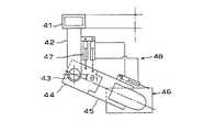
同提案によるセグメントエレクタ装置は、図5に示すように旋回ドラム41から機械後方に延出する固定ブラケット42上に回転自在な垂直軸43を設け、同垂直軸43の下端に固設された水平回動ブラケット44に平行リンク45を介して、エレクタヘッド46をヨーイング角方向に回動可能に取り付けるとともに、前記固定ブラケット42と回動ブラケット44との間に前記エレクタヘッド46をシールド本体の前後方向に移動させるための水平回動用ジャッキ47を介装している。また、前記平行リンク45と前記エレクタヘッド46との間には、把持セグメントのヨーイング姿勢を維持するためのヨーイング角補正手段48が設けられている。
【0010】
上記構成によれば、シールド掘進機のエレクタヘッド46は、水平回動用ジャッキ47を駆動させることにより垂直軸周りの前後方向に回動する。このエレクタヘッド46の回動により、エレクタヘッド46に装着されたセグメント把持手段46aはトンネルの前後方向に移動する。
【0011】
従って、セグメント供給位置に搬入されたセグメントをそれより前方のセグメント組立位置へ移動する際に、エレクタヘッド46は垂直回転軸周りの水平面内を前後方向に旋回するため、同エレクタヘッド46に把持されたセグメントはトンネル上下方向には変位のない動きとなるので、既設セグメントや周辺機器 等との干渉を回避できる。また、前記エレクタヘッド46に設置されたヨーイング角補正手段48がエレクタヘッド46の旋回と逆方向に回動させてヨーイング角を自動的に補正するため、エレクタヘッド46が前後方向に旋回しても把持セグメントはその適正な組立姿勢が維持される。
【0012】
【発明が解決しようとする課題】
しかして、前述のセグメントエレクタ装置によれば、エレクタヘッドの旋回ドラム径方向の動作が固定ブラケットの2点を枢軸とする平行リンクによる上下方向の回動によりなされるため、エレクタヘッドの運動は直動とはならず、旋回ドラムの径に直交する左右の方向にずれ、正確な垂直方向の直線運動が得られない。そのため、この左右方向のずれを補正するための制御回路を有する格別のヨーイング補正手段と複雑な機構を採用しなければならず、コストアップと保守管理の煩雑化を招き、セグメント組立作業の能率化を実現させることを難しくしている。
【0013】
本発明は前述の課題を解決すべくなされたものであり、詳しくは機構が簡単でしかも格別の補正手段を要することなく、正確に且つ安全に覆工作業を効率的に実現できるシールド掘進機のセグメントエレクタ装置を提供することを目的としている。
【0014】
【課題を解決するための手段および作用効果】
かかる目的は、本発明の主要な構成をなすシールド掘進機の後胴部の軸周りを旋回自在に装着された旋回ドラムに固設され、シールド掘進機により掘削されたトンネルの内壁に沿ってセグメントを組み立てるためのセグメントエレクタ装置において、前記旋回ドラムから後方に延設された支持部材と、同支持部材に設置され前記旋回ドラムの弦方向に進退する直動部材と、同直動部材に連結され、同直動部材の直進方向の直線周りを回動可能であって、且つ同直進方向に平行な前記旋回ドラムの直径上近傍まで延設された延設腕材と、同延設腕材の先端部に設置されたエレクタヘッド部とを備えてなることを特徴とするシールド掘進機のセグメントエレクタ装置により達成される。
【0015】
いま、新設セグメントがセグメント搬入位置に搬入される間は、前記直動部材に固設された延設腕材の先端のエレクタヘッドは前記搬入位置の垂直線上を上昇してセグメントの直上で同セグメントの搬入と干渉しない位置まで移動している。セグメントの搬入が完了すると、前記延設腕材は前記待機位置から垂直に下降して、エレクタヘッドを次回に組み立てられるセグメントの把持位置まで移動させ、同セグメントを把持する。このときのセグメントの待機姿勢を、以降の延設腕材の旋回による姿勢変化を考慮して、旋回後のセグメント姿勢が組立時の姿勢となるように予めセットしておけば、上記先願に係る発明のように格別のヨーイング角補正手段などを必要としない。勿論、セグメントの待機姿勢を前述のようにセットすることが難しい場合には、前記先顔に係る発明と同様にヨーイング角補正手段を設けることもできる。
【0016】
また、前記支持部材の突出寸法はエレクタヘッド部が垂直線に沿って確実に昇降するため、エレクタヘッド部に必要最小限の昇降ストロークが確保される長さがあれば十分であり、また前記延設腕材の延在長さも前記昇降ストローク並びに単一のセグメント寸法により決まる最小寸法で足りるため、装置の専有空間を必要最小限に押さえることができ、経済性と安全性とを容易に確保しやすくしている。
【0017】
いま、前記セグメントを把持したのち、前記延設腕材は垂直軸線を中心にして水平方向に回動するとともに、旋回ドラムを組立位置まで旋回させ、同セグメントを組立位置と相対する離間位置まで移送する。このとき、同セグメントの把持姿勢は前述のように組立時の姿勢となっている。ここで、前記直動部材が作動され、前記セグメントはセグメント組立位置へと直進してセットされる。
【0018】
前記支持部材に前記直動部材の直進方向を案内する直動部材ガイド部を設けておけば、前記直動部材の直動が確保できるため好ましい。また、前記直動部材の駆動手段として、前記支持部材に液圧シリンダを固設し、同液圧シリンダにより前記直進部材を駆動することが構造が簡単で且つ制御のしやすさから望ましいが、ラックとピニオン等からなる他の回転駆動手段を採用してもよい。同様に、前記延設腕材の回動手段として液圧シリンダを採用することが望ましく、その場合に同液圧シリンダは前記直動部材と延設腕材との間に介装される。
【0019】
以上説明したように本発明によれば、同一出願人による先の特願平7−246779号の発明と同様に、エレクタヘッド部が垂直な旋回軸周りを旋回するため、エレクタヘッドに把持された把持セグメントは水平面内でトンネルの前後方向に旋回し、トンネル上下方向の変位をしないため、搬入位置に搬入された把持セグメントを組立位置へ移送させる際に、既設セグメントや周辺機器等との干渉が避けられ安全性が向上する。
【0020】
また、本発明によれば前記旋回軸を昇降させる駆動手段を支持する支持部材が、前記延設腕材の最大昇降ストロークで足りるため、同支持部材の延設寸法を最小限に設定できるとともに、前記延設腕材の延設寸法も前記支持部材の延設寸法との和が旋回ドラムの半径に略等しく設定できるため、これらの運動部材の設置空間を最小限にすることが可能であり、空間の有効活用にもつながる。
【0021】
このことは、設備コストの低減を図ることと、装置の設置空間を効率的に利用することとを可能にするばかりでなく、部品点数が減少して装置の低廉化や組付け作業の容易性が確保され、しかも保守管理の煩雑さも低減されて、セグメントの組立作業の一段の短縮化が実現されることにつながり、更には完全自動化を図るためにも極めて有用な発明となる。
【0022】
また、本発明によるセグメント把持部は、エレクタヘッド部がエレクタヘッドの旋回ドラム径方向の動作時に旋回ドラムの径方向に直交する左右の方向のズレが生じる平行リンク機構ではなく、直動部材に吊持された剛体からなる延設腕材に設置されていることから、エレクタヘッド部の旋回ドラム径方向への動作が、旋回ドラムの径方向に直交する左右の方向にずれることなく性格な直線運動が得られるので、セグメントを性格にセグメント組立位置に設置することができる。加えて、左右方向のずれを補正するための制御回路を有する格別の補正手段を必要としない。
【0023】
【発明の実施の形態】
以下、本発明の好適な実施の形態を図示実施例に基づいて具体的に説明する。図1は本発明のセグメントエレクタ装置が適用されたシールド掘進機の内部構造を示す側面図、図2は本発明の前記実施例に係るセグメントエレクタ装置を示す全体正面図、図3はその要部を拡大して示す一部正面図、図4は同側面図、図5は同平面図である。
【0024】
本実施例におけるシールド掘進機100は、前胴110と後胴120とを有するテレスコピックシールド掘進構造を備えており、前胴110の前面には通常のカッタヘッド111、土砂排出管112、シールドジャッキ113、駆動モータ114等が装備され、また前動110と後胴120とを連結するジャッキ115を備えている。勿論、本発明はテレスコピック式シールト掘進機に限らず他の全てのシールド掘進機に適用が可能である。
【0025】
シールド本体101の後胴120内に旋回自在に設けられた旋回ドラム1には、図3に明示するように本発明の支持部材をなす支持フレーム2が後胴の軸線に平行に後方へ水平に突出させて固設され、この支持フレーム2の先端部には前記旋回ドラム1の径方向で且つ同フレーム2に直交させて昇降シリンダ3が固設されている。また、前記支持フレーム2の昇降シリンダ3を挟んだ部位には一対の直動部材ガイド部4が前記昇降シリンダ3に平行に固設されている。
【0026】
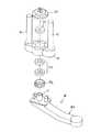
前記昇降シリンダ3の下方ロッド端は、図6に示すごとく基板5の中央部に直交して連結され、同基板5の前記ロッド端を挟んだ両端には上記直動部材ガイド部4に摺動可能に嵌挿する一対の円柱6が立設されている。本実施例における前記円柱6と一体となった前記基板5が本発明における直動部材を構成する。
【0027】
本実施例による前記基板5には、図6に示すごとくスラスト軸受7aおよび外筒7bを介して延設腕材8の基部から垂直に起立した回転軸部7が嵌め込まれ、その上端面に固着円板7cを固着してフランジ部を構成する。更に、こうして旋回自在に延設腕材8が組付けられた基板5を上述のごとく上記昇降シリンダ3のロッド端と連結部材3aを介して揺動自在に連結している。この基板5と延設腕材8との固設構造は図示実施例に限定されるものでないことは当然である。
【0028】
前記回転軸部7は旋回ドラム1の径方向と交差して延設される延設腕材8の基端部の上面に垂直に起立している。本実施例にあっては、前記延設腕材8は中空の角材からなる全体が略く字状に屈曲しており、その先端屈曲部8aは前記基板5の直動方向と平行な前記旋回ドラム1の直径上の近傍と直交するように交差状に延在するとともに、前記昇降シリンダ3の延長線にも直交している。また、前記基板5と回転軸部7とは回転駆動用シリンダ9、ヨーイング角補正シリンダ10により連結されている。回転駆動用シリンダ9は、図4に示すごとく配され、伸縮方向に作動し、上記回転軸部7を回動させて前記延設腕材8を、同図に実線と仮想線で示す間を所定の揺動角をもって前記昇降シリンダ3の軸線周りに揺動させる。
【0029】
延設腕材8の上記先端屈曲部8aの下面には、公知のセグメント把持部11aを備えたエレクタヘッド部11が設置されている。このセグメント把持部11aは、エレクタヘッド部11の長手方向に取りつけられている直動案内部材13に摺動自在に支持され、微旋回シリンダ14が前記直動案内部材13と平行に、前記エレクタヘッド11とセグメント把持部11aとの間に介装されている。
【0030】
しかして、本発明によるセグメント把持部11aは、エレクタヘッド部11がエレクタヘッドの旋回ドラム径方向の動作時に旋回ドラムの径方向に直交する左右の方向にずれが生じる平行リンク機構ではなく、直動部材5に回転可能に吊持された剛体からなる延設腕材8に設置されていることから、エレクタヘッド部11の旋回ドラム径方向への動作が、旋回ドラムの径に直交する左右の方向にずれることなく正確な直線運動が得られるので、セグメントを正確にセグメント組立位置に設置することができる。
【0031】
加えて、図2〜図4に示す実施例にあっては、前記エレクタヘッド部11に、上記先願に係る発明に類するヨーイング角補正手段が設けられている。図示例によれば、前記エレクタヘッド部11が延設腕材8の上記先端屈曲部8aの下面に軸受けを介して回動自在に支持されており、前記ヨーイング角補正手段は前記先端屈曲部8aとエレクタヘッド部11との間に配されたヨーイングジャッキ12a及びヨーイング角補正シリンダ12bを有している。このヨーイング角補正手段の構成は、本出願人による上記先願である特願平7−246779号と実質的に同一であることから、ここではその説明は省略する。
【0032】
さて、以上の構成を備えた本実施例に係るセグメントエレクタ装置により搬入されたセグメントを組立位置まで移送する動作について説明すると、セグメントが搬入位置に搬入される間は、昇降シリンダ3が伸縮方向に駆動され、エレクタヘッド部11のセグメント把持部11aをセグメント搬入位置の上方の待機位置に待機している。このときの待機位置は、セグメント搬入位置の直上からトンネル前方にずれた位置に設定すれば、セグメントの搬入時の干渉が避けられることから望ましい。
【0033】
セグメントの搬入が終了すると、上記回転駆動用シリンダ9を駆動して、回転軸部7を介して前記延設腕材8を、図4に示すセグメント組立位置Aからセグメント搬入位置Bまで回動させるとともに、前記昇降シリンダ3を伸長方向に駆動して前記延設腕材8を介してエレクタヘッド部11をセグメント把持位置へと降下させ、エレクタヘッド部11のセグメント把持部11aにより通常の操作で新設セグメントを把持する。
【0034】
次いで、昇降シリンダ3を収縮方向に駆動してセグメントを垂直上方に移送する。この移送と同時、或いは同移送後に前記回転駆動用シリンダ9を前述とは反対方向に駆動して、回転軸部7を介して前記延設腕材8を、図4に示すセグメント搬入位置Bからセグメント組立位置Aまで回動させて、エレクタヘッド11を新設セグメントのリング組立位置まで旋回させる。このとき同時か、或いはこの旋回終了後に旋回ドラム1を旋回させることにより、支持部材2、回転軸部7、延設腕材8などに随伴させて、エレクタヘッド部11を次回のセグメント組立位置に対向する位置まで移送する。
【0035】
前記エレクタヘッド部11の旋回時に、ヨーイングジャッキ12aと図示せぬ管路で連通する図示せぬヨーイング角補正シリンダ12bの伸縮量に応じてヨーイングジャッキ12aが伸縮することにより、エレクタヘッド部11は、上記延設腕材8と反対方向に回動する。すなわち、延設腕材8の揺動によって生じるセグメント把持部11aのヨーイング方向の回動により、ヨーイング角が自動的に修正される。この場合に、図示せぬ補正ジャッキの伸縮に対応してヨーイングジャッキ12aが収縮・伸長する。
【0036】
ところで、既述したように、本発明にあっては、延設腕材8の揺動時のセグメント把持姿勢を、セグメント搬入位置から組立位置へとエレクタヘッド部11を旋回(前後動)させることによって生じるセグメント姿勢のヨーイング角変動分を考慮して、旋回後のセグメント姿勢が組立位置において適正な姿勢となるように搬入時の待機姿勢を予め設定しておけば、後述する組立位置に移送されるセグメントに対する格別の補正手段は不要となる。
【0037】
前述の移送が終了すると、前記昇降シリンダ3は伸長方向に駆動され、前記延設腕材8を介してエレクタヘッド部11をセグメント組立位置へと接近させ、通常の操作で既設セグメントに対して位置合せしながら新設セグメントの把持を解いたのちに組立てを完了させる。なお、前述の昇降シリンダ3の駆動時には、上記支持フレーム2に固設した一対の直動部材ガイド部4に、前記昇降シリンダ3の下方ロッド端に固設された上記基板5の一対の円柱6が嵌挿されて摺動するため、前記基板5に上記回転軸部7及び延設腕材8を介して取り付けられたエレクタヘッド部11は前記支持フレーム2に対して直交する軌道上を正確に往復動する。
【0038】
エレクタヘッド部11によるセグメントの把持が解除されると、昇降シリンダ3が収縮方向に駆動されて、空のエレクタヘッド部11を組立位置から離間方向に直動させる。このあと、旋回ドラム1を前記エレクタヘッド部11の設定位置が同旋回ドラム1の軸線を通る垂直線上に位置するまで旋回させ、次回のセグメント移送に備える。
【0039】
なお、上述の説明は本発明の一実施例に過ぎず、新設セグメントの旋回移送にあたって同セグメントを垂直線上を直進させることと、同セグメントを水平面内で旋回させることとの各構成を少なくとも備え、本発明の精神を逸脱しないかぎりは多様な設計変更が可能であり、或いは前記構成に加えて従来から知られた様々な機構や制御手段を組み合わせて適用することをも当然に包含するものである。
【図面の簡単な説明】
【図1】本発明の代表的な実施例に係るセグメントエレクタ装置を適用したシールド掘進機の内部構成の一例を示す側面図である。
【図2】同セグメントエレクタ装置の要部全容を示す正面図である。
【図3】同側面図である。
【図4】同セグメントエレクタ装置の動作を説明する平面図である。
【図5】図4に対応する先に提案されたセグメントエレクタ装置の機構を模式的に示す動作説明図である。
【図6】本発明における延設腕材の支持機構例を示す分解斜視図である。
【符号の説明】
1 旋回ドラム
2 支持フレーム(支持部材)
3 昇降シリンダ
3a 連結部材
4 直動ガイド部
5 基板(直動部材)
6 円柱
7 回転軸部
7a スラスト軸受
7b 外筒
7c 固着円板
8 延設腕材
8a 先端屈曲部
9 回転駆動用シリンダ
11 エレクタヘッド部
11a セグメント把持部
12a ヨーイングジャッキ
12b ヨーイング角補正シリンダ
13 直動案内部材
14 微旋回シリンダ
100 シールド掘進機
101 シールド本体
110 前胴
111 カッタヘッド
112 土砂排出管
113 シールドジャッキ
114 駆動用モータ
115 ジャッキ
120 後胴[0001]
BACKGROUND OF THE INVENTION
The present invention relates to a segment erector apparatus of a shield machine for assembling a segment along an inner wall of a tunnel, and more particularly, to minimize the installation space of the segment erector apparatus in the shield machine and rational movement of the erector head The present invention relates to a segment erector apparatus for a shield machine that realizes a range, ensures safety, and facilitates segment alignment.
[0002]
[Prior art]
As a main operation of the segment erector apparatus of the shield machine, the segment may be transferred from the loading position to the assembly position. Generally, this carry-in position substantially coincides with the segment assembly position in the front-rear direction. In this transfer, after moving the erector head to the carry-in position of the segment carried into the shield tail portion, the erecter head is lowered to the grip position of the segment to be gripped, and the segment is gripped, and then the segment is gripped. Then, it is lifted once and then transferred to above the assembly position, brought to the assembly position and set. When a new segment is carried into the carry-in position of the shield tail portion, it is necessary to retract the erector head from the same position to a position where it does not interfere.
[0003]
The transfer operation described above needs to be rationally operated in a narrow space so as not to come into contact with surrounding equipment and to ensure safety for workers. In consideration of such points, those disclosed in, for example, Japanese Patent Laid-Open No. 8-105297 previously developed by the present applicant, Japanese Utility Model Laid-Open No. 4-138497, Japanese Patent Laid-Open No. 5-18195, etc. There is.
[0004]
Among these prior arts, the segment erector apparatus disclosed in Japanese Utility Model Laid-Open No. 4-138497 has a portal frame having a segment gripping mechanism at the top, which can be moved in the radial direction and swiveled in the front-rear direction. It is supported by a drum. The revolving drum and the bracket of the portal frame are connected by a jack, and the segment gripping mechanism is swung up and down together with the portal frame by the expansion and contraction of the jack.
[0005]
Further, the segment erector device disclosed in Japanese Patent Laid-Open No. 5-18195 has a plurality of segment lifting / lowering devices extending rearward from the swiveling drum into the existing segment. The slide device is extended to above the existing segment, and the new segment is selectively gripped and lifted there.
[0006]
Further, the segment erector apparatus disclosed in the above-mentioned Japanese Patent Application Laid-Open No. 8-105297 moves the segment from the segment standby position to the segment assembly position by two sets of four-bar parallel link mechanisms operating in a vertical plane. The shield body of the shield machine is divided into a front body and a rear body, and a revolving drum is rotatably supported around the axis of the shield body inside the rear body, and a segment erector attached to the revolving drum The apparatus has two sets of parallel links connected in series, and an erector head is attached to the tip of the parallel links extending rearward.
[0007]
That is, the movement of the shield body of the conventional segment elector apparatus in the front-rear direction is roughly divided into two methods: a case where it swings up and down and moves in the front-rear direction, and a case where it moves linearly back and forth. there were. In the case of a segment erector apparatus using a swinging method, the position and posture of the segment change during and after the movement change, so that interference with existing segments and gripping workability are poor. On the other hand, in the segment erector apparatus using the linear movement method, the posture of the segment is constant, but the structure is large and complicated, the assembling workability of the segment is poor, and the price is high.
[0008]
In view of this situation, the present applicant, following the above-mentioned proposal, as Japanese Patent Application No. 7-24679, further improved the segment so that it can be moved easily and efficiently while maintaining a certain posture from the supply position to the assembly position. An additional segment erector device was proposed.
[0009]
As shown in FIG. 5, the proposed segment erector apparatus is provided with a rotatable
[0010]
According to the above configuration, the
[0011]
Therefore, when the segment carried into the segment supply position is moved to the segment assembly position ahead of it, the erector head 46 pivots in the front-rear direction in the horizontal plane around the vertical rotation axis, and is thus gripped by the
[0012]
[Problems to be solved by the invention]
Thus, according to the above-described segmented erector device, the movement of the erector head in the radial direction of the rotating drum is performed by the vertical rotation by the parallel link with the two points of the fixed bracket as the pivots. It does not move, but shifts in the right and left directions orthogonal to the diameter of the swiveling drum, and an accurate vertical linear motion cannot be obtained. For this reason, special yawing correction means and a complicated mechanism having a control circuit for correcting this lateral shift must be adopted, resulting in increased costs and complicated maintenance management, and streamlined segment assembly work. Making it difficult to realize.
[0013]
The present invention has been made to solve the above-described problems, and in detail, a shield machine capable of efficiently and efficiently realizing lining work accurately and safely without requiring a special correction means. It aims at providing a segment erector apparatus.
[0014]
[Means for solving the problems and effects]
The object is to fix the segment along the inner wall of the tunnel excavated by the shield machine, fixed to the swivel drum that is pivotally mounted around the axis of the rear trunk of the shield machine that constitutes the main structure of the present invention. In the segment erector apparatus for assembling, a support member extending rearward from the revolving drum, a linear motion member installed on the support member and moving forward and backward in the chord direction of the revolving drum, and connected to the linear motion member An extending arm member that can be rotated around a straight line inthe rectilinear direction of the linearmotion member and that extends to the vicinity of thediameter of the swiveling drum parallel to the rectilinear direction; and This is achieved by a segment erector device for a shield machine, comprising an erector head part installed at the tip.
[0015]
Now, while the new segment is being carried into the segment carry-in position, the erector head at the tip of the extended arm fixed to the linear motion member rises above the vertical line of the carry-in position, and the same segment immediately above the segment. It has been moved to a position where it does not interfere with the loading. When the loading of the segment is completed, the extended arm member descends vertically from the standby position, moves the erector head to the segment gripping position to be assembled next time, and grips the segment. If the standby posture of the segment at this time is set in advance so that the segment posture after turning becomes the posture at the time of assembly in consideration of the posture change due to the subsequent turning of the extended arm material, Unlike the invention, no special yawing angle correction means or the like is required. Of course, when it is difficult to set the standby posture of the segment as described above, a yawing angle correction means can be provided as in the invention related to the front face.
[0016]
In addition, the projecting dimension of the support member is sufficient to ensure that the erector head part ascends and descends along the vertical line, so that the erector head part has a minimum required elevation stroke. The extension length of the arm material is also the minimum dimension determined by the lifting stroke and the single segment dimension, so that the space occupied by the device can be kept to the minimum necessary, and economic and safety can be easily secured. It is easy.
[0017]
Now, after gripping the segment, the extended arm member rotates in the horizontal direction about the vertical axis, and the swiveling drum is swung to the assembly position, and the segment is transferred to the spaced position opposite to the assembly position. To do. At this time, the gripping posture of the segment is the posture at the time of assembly as described above. Here, the linear motion member is actuated, and the segment is set by moving straight to the segment assembly position.
[0018]
It is preferable to provide a linear motion member guide portion that guides the linear movement direction of the linear motion member on the support member, because the linear motion of the linear motion member can be ensured. Further, as a drive means for the linear motion member, it is desirable from the viewpoint of simple structure and ease of control that a hydraulic cylinder is fixed to the support member and the linear movement member is driven by the hydraulic cylinder. You may employ | adopt the other rotational drive means which consists of a rack, a pinion, etc. Similarly, it is desirable to employ a hydraulic cylinder as a rotating means for the extended arm member. In this case, the hydraulic cylinder is interposed between the linear motion member and the extended arm member.
[0019]
As described above, according to the present invention, as in the invention of the previous Japanese Patent Application No. 7-24679 by the same applicant, the erector head portion is held by the erector head because it circulates around the vertical pivot axis. Since the gripping segment pivots in the horizontal direction in the longitudinal direction of the tunnel and does not move in the vertical direction of the tunnel, there is no interference with existing segments or peripheral equipment when the gripping segment carried into the loading position is transferred to the assembly position. It is avoided and safety is improved.
[0020]
Further, according to the present invention, since the support member that supports the driving means for raising and lowering the swivel shaft is sufficient for the maximum lifting stroke of the extended arm member, the extension dimension of the support member can be set to a minimum, Since the extension dimension of the extension arm member and the extension dimension of the support member can be set substantially equal to the radius of the revolving drum, it is possible to minimize the installation space of these moving members, It also leads to effective use of space.
[0021]
This not only makes it possible to reduce the equipment cost and efficiently use the installation space of the equipment, but also reduces the number of parts, making the equipment cheaper and easier to assemble. Is ensured, and the complexity of maintenance management is reduced, which leads to a further shortening of the assembly work of the segments, and is an extremely useful invention for achieving full automation.
[0022]
In addition, the segment gripping portion according to the present invention is not a parallel link mechanism in which a deviation in the left and right directions perpendicular to the radial direction of the swiveling drum occurs when the electre head portion operates in the radial direction of the swiveling drum. Since the arm is installed on the extended arm made of a rigid body, the movement of the erector head in the radial direction of the rotating drum does not deviate in the left and right directions perpendicular to the radial direction of the rotating drum. Therefore, the segment can be installed at the segment assembly position. In addition, no special correction means having a control circuit for correcting the shift in the left-right direction is required.
[0023]
DETAILED DESCRIPTION OF THE INVENTION
DESCRIPTION OF EXEMPLARY EMBODIMENTS Hereinafter, preferred embodiments of the invention will be specifically described with reference to the illustrated examples. FIG. 1 is a side view showing the internal structure of a shield machine to which the segment erector apparatus of the present invention is applied, FIG. 2 is an overall front view showing the segment erector apparatus according to the embodiment of the present invention, and FIG. 4 is an enlarged partial front view, FIG. 4 is a side view thereof, and FIG. 5 is a plan view thereof.
[0024]
The
[0025]
As shown in FIG. 3, a
[0026]
As shown in FIG. 6, the lower rod end of the elevating
[0027]
As shown in FIG. 6, the
[0028]
The
[0029]
On the lower surface of the distal end bending portion 8a of the
[0030]
Thus, the
[0031]
In addition, in the embodiment shown in FIGS. 2 to 4, the
[0032]
Now, the operation of transferring the segment carried by the segment erector apparatus having the above-described configuration to the assembly position will be described. While the segment is carried into the carry-in position, the elevating
[0033]
When the loading of the segment is completed, the
[0034]
Next, the
[0035]
When the
[0036]
By the way, as already described, in the present invention, the segment gripping posture when the extending
[0037]
When the above-described transfer is completed, the
[0038]
When the gripping of the segment by the
[0039]
In addition, the above description is only one embodiment of the present invention, and includes at least each configuration of moving the segment straight on a vertical line and swirling the segment in a horizontal plane when swiveling and transferring the new segment, Various design changes are possible without departing from the spirit of the present invention, or it is a matter of course to include various combinations of conventionally known mechanisms and control means in addition to the above configuration. .
[Brief description of the drawings]
FIG. 1 is a side view showing an example of an internal configuration of a shield machine using a segment erector apparatus according to a typical embodiment of the present invention.
FIG. 2 is a front view showing the entire main part of the segment erector apparatus.
FIG. 3 is a side view of the same.
FIG. 4 is a plan view for explaining the operation of the segment erector apparatus.
FIG. 5 is an operation explanatory view schematically showing the mechanism of the segment erector apparatus previously proposed corresponding to FIG. 4;
FIG. 6 is an exploded perspective view showing an example of a support mechanism for the extended arm member according to the present invention.
[Explanation of symbols]
1 Rotating
3 Lifting cylinder
6
Claims (4)
Translated fromJapanese前記旋回ドラム(1)から後方に延設された支持部材(2)と、
同支持部材(2)に設置され前記旋回ドラム(1)の弦方向に進退する直動部材(5)と、
同直動部材(5)に連結され、同直動部材(5)の直進方向の直線周りを回動可能であって、且つ同直進方向に平行な前記旋回ドラム(1)の直径上近傍まで延設された延設腕材(8)と、
同延設腕材(8)の先端部に設置されたエレクタヘッド部(11)と、
を備えてなることを特徴とするシールド掘進機のセグメントエレクタ装置。In a segment erector apparatus for assembling a segment along the inner wall of a tunnel fixed to a revolving drum that is mounted so as to be able to swivel around the axis of the rear trunk of the shield machine,
A support member (2) extending rearward from the revolving drum (1);
A linear motion member (5) installed on the support member (2) and moving forward and backward in the direction of the string of the revolving drum (1);
Connected tothe linear motion member (5) and capable of rotating around a straight line inthe linear motion direction of the linearmotion member (5) and parallel tothe linear motion direction to the vicinity of theupper diameter of the swiveling drum (1) An extended arm material (8),
An erector head (11) installed at the tip of the extended arm (8);
A segment erector apparatus for a shield machine, comprising:
Priority Applications (1)
| Application Number | Priority Date | Filing Date | Title |
|---|---|---|---|
| JP02237997AJP3701425B2 (en) | 1997-02-05 | 1997-02-05 | Segment erector device for shield machine |
Applications Claiming Priority (1)
| Application Number | Priority Date | Filing Date | Title |
|---|---|---|---|
| JP02237997AJP3701425B2 (en) | 1997-02-05 | 1997-02-05 | Segment erector device for shield machine |
Publications (2)
| Publication Number | Publication Date |
|---|---|
| JPH10220190A JPH10220190A (en) | 1998-08-18 |
| JP3701425B2true JP3701425B2 (en) | 2005-09-28 |
Family
ID=12081025
Family Applications (1)
| Application Number | Title | Priority Date | Filing Date |
|---|---|---|---|
| JP02237997AExpired - Fee RelatedJP3701425B2 (en) | 1997-02-05 | 1997-02-05 | Segment erector device for shield machine |
Country Status (1)
| Country | Link |
|---|---|
| JP (1) | JP3701425B2 (en) |
- 1997
- 1997-02-05JPJP02237997Apatent/JP3701425B2/ennot_activeExpired - Fee Related
Also Published As
| Publication number | Publication date |
|---|---|
| JPH10220190A (en) | 1998-08-18 |
Similar Documents
| Publication | Publication Date | Title |
|---|---|---|
| CN104912484B (en) | Coal Full-automatic mine roofboltier | |
| CN210115911U (en) | Automatic operation device that assembles of open-type TBM steel bow member | |
| ITMI20130360A1 (en) | DRILLING MACHINE TO PERFORATE FOR EXAMPLE LANDS AND / OR ROCKY FORMATIONS | |
| JP3701425B2 (en) | Segment erector device for shield machine | |
| CN221838250U (en) | A vertical shaft drilling rig | |
| CN209908427U (en) | Racking platform manipulator | |
| CN210422464U (en) | Coring and drilling machine | |
| CN110500111A (en) | A kind of tunnel multifunctional operation trolley | |
| JP2000198426A (en) | Frame structure of vehicle with outrigger | |
| JP3542470B2 (en) | Telescopic leader device for soft ground improvement machine | |
| JP3845254B2 (en) | Segment erector apparatus and shield machine using the same | |
| JP2001049999A (en) | Reinforcement segment assembly device | |
| CN222848156U (en) | Pneumatic drilling trolley | |
| CN222478625U (en) | Pitching drilling type rescue drilling machine | |
| CN222810762U (en) | Main manipulator positioning system | |
| JPH03296000A (en) | segment erecta | |
| JP3682788B2 (en) | Segment erector device for shield machine | |
| JP3340102B2 (en) | Electa device for multiple shield excavator | |
| JP3769662B2 (en) | Segment erector | |
| JP2538560Y2 (en) | Segment assembly equipment for tunnel excavators | |
| JPH0711899A (en) | Shield excavator segment erector | |
| JP3019256B2 (en) | Segment assembling method and segment assembling apparatus | |
| JP2000352300A (en) | Erector device and tunnel excavator | |
| JP4477745B2 (en) | Tunnel inner wall cutting machine | |
| JPH11270267A (en) | Pile-driver |
Legal Events
| Date | Code | Title | Description |
|---|---|---|---|
| A977 | Report on retrieval | Free format text:JAPANESE INTERMEDIATE CODE: A971007 Effective date:20050411 | |
| A131 | Notification of reasons for refusal | Free format text:JAPANESE INTERMEDIATE CODE: A131 Effective date:20050419 | |
| A521 | Written amendment | Free format text:JAPANESE INTERMEDIATE CODE: A523 Effective date:20050601 | |
| TRDD | Decision of grant or rejection written | ||
| A01 | Written decision to grant a patent or to grant a registration (utility model) | Free format text:JAPANESE INTERMEDIATE CODE: A01 Effective date:20050712 | |
| A61 | First payment of annual fees (during grant procedure) | Free format text:JAPANESE INTERMEDIATE CODE: A61 Effective date:20050713 | |
| R150 | Certificate of patent or registration of utility model | Free format text:JAPANESE INTERMEDIATE CODE: R150 | |
| FPAY | Renewal fee payment (event date is renewal date of database) | Free format text:PAYMENT UNTIL: 20090722 Year of fee payment:4 | |
| FPAY | Renewal fee payment (event date is renewal date of database) | Free format text:PAYMENT UNTIL: 20090722 Year of fee payment:4 | |
| FPAY | Renewal fee payment (event date is renewal date of database) | Free format text:PAYMENT UNTIL: 20100722 Year of fee payment:5 | |
| FPAY | Renewal fee payment (event date is renewal date of database) | Free format text:PAYMENT UNTIL: 20100722 Year of fee payment:5 | |
| FPAY | Renewal fee payment (event date is renewal date of database) | Free format text:PAYMENT UNTIL: 20110722 Year of fee payment:6 | |
| FPAY | Renewal fee payment (event date is renewal date of database) | Free format text:PAYMENT UNTIL: 20110722 Year of fee payment:6 | |
| FPAY | Renewal fee payment (event date is renewal date of database) | Free format text:PAYMENT UNTIL: 20110722 Year of fee payment:6 | |
| FPAY | Renewal fee payment (event date is renewal date of database) | Free format text:PAYMENT UNTIL: 20120722 Year of fee payment:7 | |
| FPAY | Renewal fee payment (event date is renewal date of database) | Free format text:PAYMENT UNTIL: 20120722 Year of fee payment:7 | |
| LAPS | Cancellation because of no payment of annual fees |