JP3696606B2 - Base station equipment - Google Patents
Base station equipmentDownload PDFInfo
- Publication number
- JP3696606B2 JP3696606B2JP2003159397AJP2003159397AJP3696606B2JP 3696606 B2JP3696606 B2JP 3696606B2JP 2003159397 AJP2003159397 AJP 2003159397AJP 2003159397 AJP2003159397 AJP 2003159397AJP 3696606 B2JP3696606 B2JP 3696606B2
- Authority
- JP
- Japan
- Prior art keywords
- path
- user terminal
- wave
- downlink
- guard interval
- Prior art date
- Legal status (The legal status is an assumption and is not a legal conclusion. Google has not performed a legal analysis and makes no representation as to the accuracy of the status listed.)
- Expired - Fee Related
Links
- 238000005259measurementMethods0.000claimsdescription16
- 230000005540biological transmissionEffects0.000description30
- 230000003111delayed effectEffects0.000description21
- 230000003044adaptive effectEffects0.000description20
- 238000000034methodMethods0.000description16
- 238000004422calculation algorithmMethods0.000description11
- 238000004891communicationMethods0.000description10
- 238000010586diagramMethods0.000description8
- 239000011159matrix materialSubstances0.000description8
- 238000010295mobile communicationMethods0.000description8
- 238000004364calculation methodMethods0.000description6
- 230000005284excitationEffects0.000description5
- 238000012545processingMethods0.000description5
- 238000004088simulationMethods0.000description4
- 230000001276controlling effectEffects0.000description3
- 230000002596correlated effectEffects0.000description3
- 238000001514detection methodMethods0.000description2
- 230000006866deteriorationEffects0.000description2
- 238000009792diffusion processMethods0.000description2
- 230000000694effectsEffects0.000description2
- 238000011160researchMethods0.000description2
- 230000002238attenuated effectEffects0.000description1
- 230000015572biosynthetic processEffects0.000description1
- 239000000969carrierSubstances0.000description1
- 230000001413cellular effectEffects0.000description1
- 230000000052comparative effectEffects0.000description1
- 238000005094computer simulationMethods0.000description1
- 230000003247decreasing effectEffects0.000description1
- 238000009434installationMethods0.000description1
- 238000010606normalizationMethods0.000description1
- 230000002441reversible effectEffects0.000description1
- 238000010187selection methodMethods0.000description1
- 238000003786synthesis reactionMethods0.000description1
Images


Landscapes
- Variable-Direction Aerials And Aerial Arrays (AREA)
- Mobile Radio Communication Systems (AREA)
Description
Translated fromJapanese【0001】
【発明の属する技術分野】
本発明は、複数のユーザ端末に対し、アレーアンテナを使用しMC-CDMA伝送方式に従ってガードインターバル区間を有した信号を送信する基地局装置に関するものである。
【0002】
【従来の技術】
近年、高速・広帯域伝送サービスを目指した新世代移動通信方式の検討が始まっている。サービスを有限の周波数資源で提供するためには、一層の周波数有効利用を図る必要があり、そのための伝送方式として、OFDM(Orthogonal Frequency Division Multiplexing)変調を用いた符号分割多元接続方式であるMC−CDMA(Multicarrier -Code Division Multiple Access)方式が検討されている。
このMC-CDMA方式では、1または複数ユーザの各データシンボル系列、および、必要に応じてパイロットシンボル系列が、互いに異なる拡散符号で符号多重されている。この符号多重は各キャリア(サブキャリア)について行われる。キャリア周波数は互いに直交する周波数配置を有する。
新世代移動通信で有力視されているマイクロ波帯では従来の周波数帯よりも伝搬損失が増大する。従って、基地局にアダプティブアレーアンテナを適用し、高利得化を図るとともに、他ユーザ干渉を効果的に抑圧することにより、収容可能なトラフィックを増大させることが検討されている。
【0003】
まず、アダプティブアレーアンテナにより他ユーザ干渉を抑圧する原理を簡単に説明しておく。
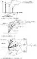
図6は、アダプティブアレーアンテナを用いたCDMA移動通信システムの例を示す説明図である。
図中、41はユーザ1の移動局、42はユーザ2の移動局、44は基地局、45は基地局のアダプティブアレーアンテナである。その素子数は任意である。受信時に各アンテナ素子で受けた信号に乗算するアンテナウエイトを制御することによって、受信時の指向性パターンを自由に制御できる。
従って、各移動局41,42からの送信波を基地局44で受信する上り回線において、ユーザ1の移動局41に対しては、ユーザ1指向性51として示したビームパターンで受信する。ユーザ1指向性51は、ユーザ1の移動局41方向にメインローブを有し、ユーザ2の移動局42の方向にヌル(ビームヌル)を有する。同様に、ユーザ2指向性52は、ユーザ2の移動局42方向にメインローブを有し、ユーザ1の移動局41の方向にヌルを有する。
その結果、アダプティブアレーアンテナにより一方の移動局の方向にメインローブを向けて受信するときに、他方の移動局の方向はヌルであるから、他方の移動局からの送信された干渉波が抑圧される。
一方、下り回線において、基地局から送信する場合は、アダプティブアレーアンテナ45により、一方の移動局の方向にメインローブを向けて送信するときに、他方の移動局の方向にヌルが向くから、他方の移動局で、一方の移動局へ向けられた受信波が干渉波となって受信してしまうことが抑圧される。
【0004】
ところで、上述したOFDM変調方式においては、IDFT(逆離散フーリエ変換)の有効シンボル区間の末尾と同一波形を有効シンボル区間の先頭に付加して、これをガードインターバル(GI)区間とすることにより、先頭波(先行波)の到来時刻からガードインターバル長よりも短い遅延時間で到来する遅延波による通信品質劣化を防止している。しかし、ガードインターバル長を超える、長い遅延時間で到来する遅延波が存在すると、OFDM信号のシンボル間干渉(ISI)を引き起こすために、同一の移動局からの遅延波であったとしても、受信品質が大幅に劣化するという問題がある。
そこで、このようなガードインターバル長を超える遅延波についても、上述した他ユーザパスの抑圧と同様に、アダプティブアレーアンテナの指向性利得のヌルを向けるという方法で抑圧する検討がなされている。
【0005】
例えば、非特許文献1では、地上波デジタルテレビジョン放送用のOFDM変調信号の受信において、ガードインターバル区間を超える遅延波の到来方向にも指向性パターンのヌルを向けている。ただし、この文献では、素波分離を目的とするため、先頭波のみを希望波とし、ガードインターバル区間内の遅延波の到来方向に対してもヌルを向けている。
また、非特許文献2では、上述したOFDM変調方式をDS−CDMAの移動通信、すなわち、冒頭で述べたMC−CDMAに適用した場合に、ガードインターバル区間内にある、先頭波を含む1または複数の到来波の1つにメインローブを向け、ガードインターバル区間内にある残りの到来波、および、ガードインターバルを超える遅延波の方向にヌルを向けて、素波分離する検討がなされている。
【0006】
以上のようなOFDM変調方式、あるいは、OFDM変調方式を用いたMC−CDMA方式でのアダプティブアレーアンテナの検討は、受信側に適用したものであった。
これに対し、送信側に適用する検討として、非特許文献3が知られている。しかし、ガードインターバル長を超える遅延波について検討されていない。また、TDD(Time Division Duplex)を前提としたもので、上り回線の受信側のウエイトをコピーして下り回線の送信側のウエイトとするものである。
しかし、FDD(Frequency Division Duplex)を対象としたものでは、下り回線と上り回線とでは搬送波周波数が大きく異なる。そのため、搬送波周波数差が広がると、上り回線で作成したアンテナウエイトをコピーしてアンテナウエイトを作成した下り回線の指向性パターンは、上り回線の指向性パターンとは異なるものとなるから、マルチパスを十分には抑圧できない。
【0007】
DS−CDMA(W−CDMA)方式であれば、従来でもFDDを対象とした検討が、例えば、非特許文献3で検討されている。上り回線での移動局からの電波の到来方向情報に基いて下り回線のアンテナウエイトを計算して指向性制御を行う。
しかし、MC−CDMA方式のFDD下り回線に関し、各ユーザの移動局が、基地局から送信されたOFDM変調信号のガードインターバル長を超える長い遅延時間で到来する遅延波によるシンボル間干渉を抑圧するように、アレーアンテナの指向性利得を制御する方法は知られていなかった。
【0008】
一方、アダプティブアレーアンテナのビームフォーミング技術として、ドルフ−チェビシェフ(Dolph−Chebyshev)励振振幅分布によるものが、例えば、非特許文献5で知られている。
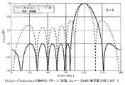
図7は、ドルフチェビシェフ・アレーアンテナの指向性利得を示すグラフである。
横軸は到来角、縦軸は指向性利得である。比較例として、アレーアンテナとしては一般的なものである、等相一様励振振幅分布の指向性利得を破線で示している。このドルフ−チェビシェフ・アレーアンテナでは、希望波方向(120°)にメインローブを向け、全てのサイドローブレベルは所定値以下に抑えている。
【0009】
さらに、このドルフ−チェビシェフ励振振幅分布によるビームフォーミングに、ヌルステアリングを組み合わせた素子共有階層型アダプティブアレーアンテナが、例えば、非特許文献6,7で知られている。
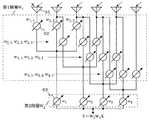
図8は、素子共有階層型アダプティブアレーアンテナの原理的構成図である。
図中、61はアンテナ素子、62は第1階層におけるアンテナウエイト、63は第2階層におけるアンテナウエイトである。
階層型アダプティブアレーアンテナは、アレーアンテナを要素アンテナとするアダプティブアレーである。アンテナウエイトを各階層に振り分け、階層毎に異なる能力を持たせるものである。
【0010】
第1階層にドルフ−チェビシェフ励振振幅分布によるビームフォーミングの能力を持たせ、第2階層にヌルステアリングの能力を持たせれば、サイドローブレベルを抑圧することができるとともに、所望の方向をヌルにすることができる。
特に、図示のような、素子共有階層型アレーアンテナでは、アンテナエレメントの1本分だけサブアレー化をずらせることにより、第2階層におけるアンテナ重みの数を増やし、生成可能なヌルの数を増やしている。
第1階層のアンテナウエイトの行列をW1とし、第2階層におけるアンテナウエイトの行列をW2とすると、出力Yは、受信信号ベクトルXに対し、次式のように、W2,W1,Xの積で表される。
【数1】
【0011】
【非特許文献1】
堀,菊間,稲垣,「電子情報通信学会論文誌 B」,Vol.J85−B, No.9,(2002−9),pp.1608-1615
【非特許文献2】
浦口,菊間,稲垣,「電子情報通信学会論文誌 B」,Vol.J83−B, No.2,(2000−2),pp.216-224
【非特許文献3】
藤井,鈴木,「電子情報通信学会技術研究報告」,2002−11,RCS2002-202,pp.59−64
【非特許文献4】
北原,宮谷,小川,大鐘,「電子情報通信学会論文誌 B」,2002−9,Vol.J85-B,No.9,pp.1665-1668
【非特許文献5】
「アンテナ工学ハンドブック」,電子情報通信学会,1980,p.208,209,213,214
【非特許文献6】
H.Yamasuge, and R.Kohno,“IEICE Trans. Commun”,Oct. 2002,Vol.E85-B,
no.10,pp.1921−1926
【非特許文献7】
山菅,青木,渡辺,河野,「電子情報通信学会技術研究報告」,2001−3,RCS2000-236,pp.101−106
【0012】
【発明が解決しようとする課題】
本発明は、上述した問題点を解決するためになされたもので、MC−CDMA方式に従ってガードインターバル区間を有した信号を送信する下り回線における、ユーザ端末側において受信される受信信号中に含まれる、ガードインターバルを超える遅延波によるシンボル間干渉(ISI)を抑圧する基地局装置を提供することを目的とするものである。
加えて、アダプティブアレーアンテナの指向性利得が小さくなるヌルの幅を広げることができる基地局装置を提供することを目的とするものである。
【0013】
【課題を解決するための手段】
本発明は、請求項1に記載の発明においては、複数のユーザ端末に対し、アレーアンテナを使用しMC-CDMA方式に従ってガードインターバル区間を有した信号を送信する基地局装置であって、上り回線受信信号の遅延プロファイルを前記各ユーザ端末別に測定する遅延プロファイル測定手段と、前記アレーアンテナを使用して受信した上り回線受信信号に基づいて、前記各ユーザ端末別にパスの到来方向を推定する到来方向推定手段と、前記遅延プロファイル測定手段により測定される前記各ユーザ端末別の遅延プロファイル、および、前記到来方向推定手段により推定されるパスの到来方向に基づいて、前記各ユーザ端末別の遅延プロファイルに下り回線での前記ガードインターバル区間を設定し、前記下り回線でのガードインターバル区間内にある、当該ユーザ端末からの少なくとも1つのパスを、当該ユーザ端末からの希望波のパスとみなし、前記下り回線でのガードインターバル区間を超える少なくとも1つのパスを、前記希望波に対する干渉波のパスとみなし、前記希望波のパスの到来方向への指向性利得が大きく、前記干渉波のパスの到来方向への指向性利得が小さくなるように、前記アレーアンテナの下り回線の指向性を制御する下り回線指向性制御手段を有するものである。
従って、送信側におけるアレーアンテナの指向性制御により、ユーザ端末側において受信されるMC−CDMA受信信号の、ガードインターバルを超える遅延波によるシンボル間干渉(ISI)を抑圧することができる。
アレーアンテナを使用して受信した上り回線の受信信号に基づいて各ユーザ端末からの希望波のパスおよび干渉波のパスの到来方向を推定することにより、アレーアンテナの下り回線の指向性を制御することから、上下回線の搬送波周波数差の影響を受けにくい。
【0014】
下り回線指向性制御手段が希望波のパス、干渉波のパスとみなす手法には種々のものがある。
(1)先頭波のパスより下り回線でのガードインターバル区間の長さ以内にある当該ユーザ端末からの1つのパス、例えば、受信レベルの最も大きいパスを希望波のパスとみなせばよい。ただし、先頭波のパスは、必ずしも受信レベルが最大値のものではない。
(2)下り回線でのガードインターバル区間内にある当該ユーザ端末からの複数のパスをまとめて合成してもよい。その結果、アンテナの自由度を1つ消費するだけですむ。
(3)干渉の程度は、干渉波となる遅延波の受信レベルが大きいほど優勢である。
したがって、干渉波のパスと見なすものは、特に、シンボル間干渉を引き起こす下り回線でのガードインターバル区間の長さを超えるパスに関して、受信レベルが大きいパスほど優先的に干渉波のパスとみなすようにしてもよい。
【0015】
請求項2に記載の発明においては、請求項1に記載の基地局装置において、前記下り回線指向性制御手段は、加えて、当該ユーザ端末からの希望波のパスの到来方向以外に存在するサイドローブレベルが所定値以下になるように前記アレーアンテナの下り回線の指向性を制御するものである。
サイドローブレベルが低く抑えられると、単に、サイドローブレベルが低下するだけでなく、アレーアンテナの指向性利得が小さくなる角度幅(ヌルの幅)を広げることができる。その結果、ユーザ端末の移動によっても、伝送品質が急には変化しない。そのため、セルラー方式等の移動通信に適用した場合においては、通信中の伝送品質を常に一定基準以上確保するための無線アクセス制御におけるアクセス可否判定が容易になる。また、無線LAN等の広帯域無線アクセスシステムに適用した場合においては、通信中の伝送品質を一定基準以上に保つための無線アクセス制御が容易になる。
【0016】
なお、アンテナの自由度に余裕があるか否かを判定する手段を設けて、アンテナの自由度に余裕があるときには、請求項2記載の下り回線指向性制御を行うようにしてもよい。
すなわち、希望波のパスの到来方向および前記干渉波のパスの到来方向に対する指向性利得の制御により、アンテナの自由度に余裕がなくなったと判定したときは、請求項1に記載の回線指向性制御手段を機能させ、アンテナの自由度にまだ余裕があると判定したときには、加えて、当該ユーザ端末からの希望波のパスの到来方向以外に存在するサイドローブレベルが所定値以下になるようにアレーアンテナの下り回線の指向性を制御するものであってもよい。
【0017】
【発明の実施の形態】
図1は、本発明の実施の一形態を説明するための基地局の、送信側の一例を示すブロック構成図である。
1はi番目のユーザの送信データを入力し、M個の並列データに変換して、キャリア毎に分配する直並列変換部である。
21〜2Mはキャリア毎に設けられた拡散およびユーザ多重化部である。
第1番目のキャリア1に対する拡散および多重化部21について説明する。拡散部(乗算器)3において、ユーザiの分配されたデータ(データシンボル)は、拡散符号ci1(t)と乗算されて時間軸方向に符号拡散される。各ユーザに割り当てられるこの拡散符号ci1(t)は、各キャリア1〜Mによって異ならせてもよいが、全てのキャリア1〜Mについて同一の拡散符号を割り当ててもよい。
なお、説明を簡単にするため、1次変調は一例としてBPSKであるとし、1次変調ブロックの図示を省略した。
【0018】
拡散部3の出力は、コピー部4にて、符号拡散されたデータシンボルがアンテナエレメント1〜Kの系統にコピーされ、それぞれ、アンテナウエイト重み付け部51〜5Kに供給される。アンテナウエイトw1i1(t)〜wKi1(t)は、アンテナウエイト計算部16において計算されたものを用いる。下付文字の左側はアンテナ素子の素子番号、下付文字の右側はユーザ番号、上付文字はキャリア番号である。
アンテナウエイト重み付け部51〜5Kの出力は、さらに、合成部(MUX)61〜6Kに供給され、ここで、他ユーザの同様の拡散部の出力と加算合成されて、全ユーザの符号多重化された拡散信号が、1〜K本のアンテナエレメント系統に出力される。
【0019】
各キャリア1〜M毎に設けられた拡散およびユーザ多重化部21〜2Mから第1〜第Kのアンテナエレメント系統に出力される拡散信号は、それぞれ、離散逆フーリエ変換(IDFT)部71〜7Kに入力される。
第1の素子系統について説明する。離散逆フーリエ変換は、データシンボルが拡散符号ci1(t)で拡散された後のチップデータ単位で行われ、このチップデータ単位の時間幅が、離散逆フーリエ変換されて得られるOFDM変調信号の1シンボル(OFDMシンボル)の時間幅に対応する。
OFDM変調信号は、ガードインターバル付加部81において、OFDM変調信号の1シンボル毎にガードインターバル(GI)区間が付加される。このガードインターバル(GI)区間は、OFDM変調信号の有効シンボル区間の末尾と同一の波形であって、有効シンボル期間の先頭に付加されたものである。
次に、D/A変換部91で時間軸波形に変換され、乗算器101において、発振器111の出力と乗算されて周波数変換され、デュプレクサ121を経てアレーアンテナの第1のアンテナ素子131に出力される。
【0020】
他の素子系統についても同様である。逆フーリエ変換された拡散信号にガードインターバルが付加された信号を変調しK本の素子に出力され、K本のアンテナ素子131〜13K全体として、アンテナウエイトw1i1(t)〜wKi1(t)の計算アルゴリズムに従った、各ユーザi毎の送信指向性パターンが形成される。
上述したアンテナウエイトw1i1(t)〜wKi1(t)は、基地局における上り回線の受信信号により各ユーザ端末からの電波の到来方向を推定した情報に基づいて決定する。
上り回線と下り回線とは、周波数帯域が分離されており、FDDとして多重化されている。上り回線と下り回線とでは、伝送方式,伝送帯域幅を同じにする必要はない。しかし、上り回線の伝送方式としては、たとえば、DS−CDMA方式、MC−CDMA方式等のように、遅延パスを高精度に分離できる遅延プロファイル測定が可能な伝送方式を用いることを前提とする。
【0021】
アンテナ素子131〜13Kで受信された信号は、遅延プロファイル測定部14に入力され、下り受信回線がDC-CDMA方式であれば、各ユーザiの上り回線の拡散符号を乗算して逆拡散を行うことにより、ユーザ別に各遅延波が分離された遅延プロファイルを作成し、ユーザ別の到来方向推定部15に出力する。下り受信回線がMC-CDMA方式であれば、例えば、OFDM変調された各ユーザのパイロット信号とそのレプリカとの相関検出により遅延プロファイルを作成すればよい。
遅延プロファイル測定部14は、アンテナ素子131〜13Kからの各受信信号について遅延プロファイルを測定して平均化したり、1つのアンテナ素子からの信号についてのみ遅延プロファイルを測定したり、具体化に際し、種々の構成をとることができる。
到来方向推定部15においては、ユーザi別に時間分離した到来波の方向を推定し、アンテナウエイト計算部(Antenna Weight Controller)16に出力する。
アンテナウエイト計算部16では、ある希望ユーザiのアンテナウエイトを、遅延プロファイル測定部14で検出された、ある希望ユーザiのパスおよび他ユーザのパスに関し、到来方向推定部15により推定された、それらの到来方向推定結果を用いて、ある希望ユーザiに最適な送信指向性パターンとなるようにアンテナウエイトを計算する。
【0022】
図2は、図1に示した実施の一形態における第1の動作例を示すフローチャートである。
図3は、図1に示した実施の一形態における遅延プロファイル測定結果および到来方向推定結果を示す説明図である。
図3を参照しながら、図2の処理を順に説明する。
S21は、上り回線の受信側において、スライディング相関、マッチドフィルタ等を用いて、遅延プロファイルを測定する。
【0023】
S22において、各ユーザ端末別の遅延プロファイルにおけるガードインターバル(GI)内のパスとガードインターバル(GI)外のパスとを識別する。
まず、受信した上り回線の各ユーザ端末別の遅延プロファイルに、下り回線でのガードインターバル区間を設定する。上り回線は必ずしもMC−CDMAではないため、受信信号中にガードインターバルの区間が含まれているわけではない。ガードインターバル区間の設定は、あくまで仮想的なもので、下り回線でMC−CDMA方式により送信する際に、ユーザ端末側で、ガードインターバル区間を超える遅延波が受信されるか否かを調べるために設定する。
ガードインターバル区間は、原理的には、上り回線受信信号の各ユーザ端末別の遅延プロファイルにおける先頭波(先行波)のパスのタイミングから開始するように設定すればよい。
ただし、先頭波のパスは、必ずしも受信レベルが最大とならない。そのような場合は、例えば、受信レベルが最大となるパスから先行して、この最大の受信レベルに応じて決めた所定の閾値を超える最も先行する位置のパスを先頭波とみなし、この先頭波のパスをガードインターバル区間の開始位置とする。
【0024】
図3(a)には、各ユーザ毎に測定される遅延プロファイルが示されている。
図示の例では、ある希望ユーザの拡散符号との相関検出の結果、先頭パス#1から開始されるガードインターバルの区間に、先頭パス#1,遅延パス#2が含まれ、ガードインターバルの区間を超える以後の区間に、遅延パス#3がある。
希望ユーザの拡散符号との相関検出の結果であるから、希望ユーザ端末からのパスが測定される。しかし、他ユーザ端末からのパスの到来波も、拡散符号による処理利得分だけレベル減衰した状態で含まれている。
【0025】
S23においては、S21の遅延プロファイル測定ステップにおいて分離した各パス毎に到来方向推定をする。
例えば、遅延プロファイル測定部14は、各ユーザ端末別の遅延プロファイルを、各アンテナ素子131〜13Kの受信信号について測定している。各アンテナ素子131〜13K別の遅延プロファイル(1)〜遅延プロファイル(K)において、各ユーザ端末からのパスは、先頭波#1,第1遅延波#2,第2遅延波#3,…というように時間的に分離されている。このように時間的に分離された各ユーザ端末からのパスのそれぞれについて、遅延プロファイル(1)〜遅延プロファイル(K)で測定された、受信レベル、位相、時間差等の相違に基づいて到来波が推定される。
到来方向の具体的な推定手法としては、非特許文献2に記載されているような、MUSIC(MUltiple SIgnal Classification)やESPRIT(Estimation of Signal Parameters via Rotational Invariance Techniques)法などが知られている。
【0026】
図3(b)には、図3(a)に示した希望ユーザiのパス#1,#2,#3についての到来方向推定結果の一例を示している。
希望ユーザiのユーザ端末に対する、先頭パス#1,遅延パス#2,#3は、屋外の市街地伝搬で基地局アンテナ高が周囲の建物より高い場合には、一般に角度スプレッドが小さいので到来方向も接近している。
図3(c)には、図3(a)では省略した他ユーザa,bについて遅延プロファイル測定をして測定されたパスを含めたパスの到来方向推定結果の一例が示されている。
【0027】
S24において、S22およびS23の推定結果に基づいて、希望波とみなすパスおよび干渉波とみなすパスを選択する。
その選択の手法としては種々のものがある。
S22において、各ユーザ端末別に測定された遅延プロファイルの先頭パスよりガードインターバル区間の長さ以内のパスであると識別されたもの、図3(a)ではパス#1,#2、の中から、当該ユーザ端末(希望ユーザ端末)からの少なくとも1つのパスを、当該ユーザ端末からの希望波のパスとみなす。
第1の方法は、受信レベルの最も大きいパスを希望波のパスとみなす。
第2の方法は、下り回線でのガードインターバル区間の長さ以内のパスと識別された、当該ユーザ端末からの複数のパスを合成したものを1つの希望波とみなす。この場合、複数の希望波のパスは互いに相関があるものとみなすので、アンテナの自由度を1つ消費するだけですむ。
【0028】
また、S22において識別された、当該ユーザ端末の遅延プロファイルの上述したガードインターバル区間を超える少なくとも1つのパスを、上述した希望波に対する干渉波のパスとみなす。このような干渉波のパスとしては、図3(a)に示した、当該ユーザ端末からの遅延波のパス#3だけでない。図3(c)に示したような、他ユーザa,bからのパスが含まれている場合がある。
また、当該ユーザ端末からの先頭パスよりガードインターバル区間の長さ以内に、他ユーザ端末からのパスが含まれる可能性がある。他ユーザ端末の遅延プロファイル測定や、到来方向推定等によって、これが他ユーザ端末からのパスであると判定されれば、当該ユーザ端末に対する希望波のパスとは見なさず、干渉波のパスとみなす。
【0029】
また、干渉の程度は、干渉波の受信レベルが大きいほど優勢であると推定される。したがって、受信レベルが大きい遅延波のパスについては優先的に干渉波のパスとみなすことが好ましい。特に、シンボル間干渉を引き起こす希望ユーザ端末のガードインターバル区間の長さを超えるパスに関しては、受信レベルが大きい遅延波のパスほど優先的に干渉波のパスとみなすことが好ましい。
図3(b),図3(c)を参照して後述するように、アンテナウエイトの計算時においては、上述した希望波と見なすパスの選択および干渉波とみなすパスの選択の結果を受けて、後述する仮想的な相関行列を求めるための各パス間の相関の大きさを決定する。
例えば、希望波とみなすパスの方向への指向性利得が大きくなり、干渉波とみなすパスの方向への指向性利得を小さくなるようにするには、希望ユーザiの希望波のパス#1と、希望波のパス#2とは、互いに相関ありとみなす。また、同じパス同士の相関については相関ありとみなす。
次に、希望波のパス#1または#2と、ガードインターバル内の希望ユーザiの干渉波のパス#3、他ユーザaの干渉波のパス、他ユーザbの干渉波のパスとは、互いに無相関と見なす。
また、他ユーザaの干渉波のパスと、他ユーザbの干渉波のパスとは、互いに無相関と見なす。
【0030】
S25において、「アルゴリズム1」を実行する。
希望波のパスとみなした少なくとも1つのパスの到来方向への指向性利得を大きくし、一方、干渉波のパスとみなしたパスの到来方向への指向性利得が小さくなる(ヌルを向ける)ようにアンテナウエイトを計算して、アレーアンテナの下り回線の指向性を制御する。
その結果、逆の下り回線において、希望波のパスとみなしたパスを通って、基地局からの電波がユーザ端末に到来して受信させるようにする。また、干渉波のパスとみなしたパスを通って、基地局からの電波がユーザ端末に到来しないようにして干渉波を受信させないようにする。
なお、希望波のパスと見なしたパスが複数ある場合には、箇々のパスについてその到来方向への指向性利得を大きくしてもよいが、この複数のパスを合成したパスに対して指向性利得を大きくしたほうが、アンテナの自由度の消費を少なくして、ヌルの数を増やすことができる。
【0031】
なお、図2に示した処理ステップは一例であってこれに限らない。
基地局では、遅延プロファイル測定や到来方向推定を、本件発明とは別目的に使用している場合もある。図1の遅延プロファイル測定部14から本件発明の実施の形態に必要な測定値を入手し、到来方向推定部15から本件発明の実施の形態に必要な推定値を入手すればよい。
図2に示した処理ステップでは、希望波と見なすか干渉波とみなすかは、主として、各ユーザ端末別の遅延プロファイル測定によって、ガードインターバル区間の長さ以内の遅延かどうかで判定するように説明した。
しかし、到来方向推定など、その他の測定結果あるいは推定結果を考慮して、希望波と見なすか干渉波とみなすかを判定してもよい。すなわち、遅延プロファイル測定部14により測定される遅延プロファイル、および、到来方向推定部15により推定されるパスの到来方向に基づいて、前記アレーアンテナの下り回線の指向性を制御すればよい。
【0032】
アンテナウエイトの計算は、例えば、下り回線について、仮想的な相関行列と相関ベクトルとを計算することにより行われる。
希望ユーザiのユーザ端末を送信相手とするアンテナウエイトwiは、Wiener解として次式で与えられる。
【数2】
アダプティブアレーアンテナがガードインターバル内の希望ユーザiのパスを希望波と見なし、ガードインターバル外の希望ユーザiのパスを干渉波と見なし、および、他ユーザのパスを干渉波と見なして動作させる。
【0033】
そのため、相関行列Rxxiを計算する際、図3(a),図3(b)に示すように、ガードインターバル内の希望ユーザiのパス#1,#2と、ガードインターバル外の希望ユーザiのパス#3とが互いに無相関であるとみなす。
また、図3(c)に示した他ユーザaのパスおよび他ユーザbのパスは、それぞれ希望ユーザiのパスに対して無相関であり、他ユーザaのパスと他ユーザbのパスとの間も無相関であるとみなす。
上述した仮定のもとで、相関行列Rxxiおよび相関ベクトルrxriを計算すればよい。
また、相関ベクトルrxriを計算する際は、第iユーザのマルチパスの中で、相関があり希望波であると判断したガードインターバル内の1または複数のパスについてだけ、相関ベクトルrxriを計算し、その計算結果をベクトル加算すればよい。
【0034】
図4は、図1に示した実施の一形態における第2の動作例を説明するフローチャートである。
ステップS21からS24までは、図2に示した第1の動作例と同じであるので説明を省略する。
S24に引き続くS31において、
K-1>NI (6)
であるか否かを判定する。
ここで、Kはアンテナの素子数、すなわち、アンテナの自由度である。ガードバンドインターバル内に存在する希望波のパスは、複数本ある場合であっても合成したものについて指向性パターンを形成するようにする。従って、希望波と見なすパスの数は1として計算し、ヌルを形成するための自由度は(K-1)となる。
NIは干渉波と見なすパスの数である。
従って、S31の式が成り立つ(Yes)ときは、必要とされるヌルを形成しても、アンテナの自由度にまだ余裕があることを意味する。このようにアンテナの自由度に余裕があるか否かを判定し、アンテナの自由度に余裕がある場合(Yes)は、S32に処理を進め「アルゴリズム2」を実行するが、そうでない(No)ときは、S25に処理を進め、図2に示した第1の動作例と同様の「アルゴリズム1」を実行する。
【0035】
S32においては、希望波のパスとみなした少なくとも1つのパスの到来方向への指向性利得を大きくし、干渉波のパスとみなしたパスの到来方向への指向性利得が小さくなるようにし、加えて、希望波のパスの到来方向以外に存在するサイドローブレベルが所定値以下になるようにアンテナウエイトを計算して、アレーアンテナの下り回線の指向性を制御する。
なお、S25と同様に、希望波のパスと見なしたパスが複数ある場合には、複数のパスを合成したものに対して指向性利得を大きくするようにして、アンテナの自由度に余裕を持たせる。
【0036】
サイドローブの分布は、例えば、従来技術の説明で述べたような、第1階層にドルフ−チェビシェフ励振振幅分布によるビームフォーミングの能力を持たせ、第2階層にヌルステアリングの能力を持たせるようなアンテナウエイトを計算する。
図8に示したものは、受信時のアンテナウエイトを説明したものであったが、送信時のアンテナウエイト置きかえることができる。
なお、実際にアンテナウエイトを計算する際には、同じ結果が得られればよく、W2とW1の各アンテナウエイトを個別に計算してから乗算する必要はなく、一度の計算で行えばよい。
【0037】
サイドローブレベルが低く抑えられれば、単に、サイドローブレベルが低下するだけでなく、アレーアンテナの指向性利得が小さくなるヌルの幅(ヌルのレベル低下の広がり角度)を広げることができる。
その結果、送信相手の希望ユーザ端末が高速に移動することにより、この希望ユーザ端末において、遅延波パスの到来方向が変化しても、遅延波の受信レベルが急に増えることがない。従って、この送信相手の希望ユーザ端末に与える干渉を現状維持することができる。
一方、他ユーザ端末が高速に移動することにより、この他ユーザ端末において、受ける干渉波パスの到来方向が変化しても、干渉波のレベルが急に増えることがない。従って、この他ユーザ端末へ与える干渉を現状維持することができる。
従って、いずれのユーザ端末の移動によっても、実質的に通信中の伝送品質が急には変化しないため、通信中の伝送品質を常に一定基準以上確保するための無線アクセス制御におけるアクセス可否判定が容易になる。
【0038】
図5は、図2,図4に示した「アルゴリズム1」,「アルゴリズム2」に従ったシミュレーションによる指向性パターンを示すグラフである。
図中、横軸はパスの到来角度[deg.]、縦軸は利得[dB]である。破線は、図2に示した第1の動作例、図4に示した第2の動作例の「アルゴリズム1」のシミュレーション結果を示し、実線は、図4に示した第2の動作例における「アルゴリズム2」のシミュレーション結果を示す。
計算機シミュレーション諸元について簡単に説明しておく。1次変調はQPSK変調、中心周波数5[GHz]、サブキャリア間隔40[kHz]、サブキャリア数1024、ガードインターバル長6.25μs(OFDMシンボル長の1/4)、拡散符号利得32である。6素子半波長等間隔リニアアレーアンテナを用いた。単一ユーザ、4パスモデルを用い、各パスの電力と到来方向は正確に推定できるものとした。
また、アンテナウエイトは、比帯域が小さいので各サブキャリア毎に同じ値とし、中心周波数の値で計算した。
【0039】
ガードインターバル内にある、2つの希望波の到来角度を黒丸で示している。
両者を合成したものを1つの希望波として計算しているので、メインローブは1つである。
一方、干渉波の到来角度を×印で示している。それぞれに、ヌルが形成されている。
アンテナの自由度は6−1=5、希望波1、干渉波2であるので、自由度の余裕は、5−1−2=2である。従って、第2のアルゴリズムを適用することができ、サブローブのピークが略−40[dB]以下に抑えられる。
【0040】
図1を参照して説明したMC-CDMA方式は、時間軸方向に符号拡散させていた。
しかしMC-CDMA方式では、複数ユーザの各データシンボル系列は、時間軸方向に符号拡散させる方式と、周波数軸方向に符号拡散させる方式がある。いずれか一方のみを採用しても、伝搬路変動に応じて方式を切り替えてもよい。
周波数軸方向に拡散させる場合、例えば、各データシンボル系列の同じデータシンボルを各サブキャリアに対して共通に供給する。各ユーザに割り当てられた拡散符号は、その各チップの値を各サブキャリアに分配する。各サブキャリアにおいて、供給されたデータシンボルに各ユーザに割り当てられた拡散符号のチップの値を乗算して周波数軸方向に拡散する。この場合、離散逆フーリエ変換は、拡散符号のチップの値が乗算されたデータシンボル単位で行われ、この拡散符号のチップの値が乗算されたデータシンボル単位の時間幅が、離散逆フーリエ変換されて得られるOFDM変調信号の1シンボル(OFDMシンボル)の時間幅に対応する。ガードインターバル(GI)区間はOFDM変調信号の1シンボル毎に付加される。
【0041】
以上、本発明を移動通信システムに適用した場合について説明した。本発明は、IEEE802.11等の無線LAN(Local Area Network)のように、固定のユーザ端末を対象とした広帯域無線アクセスシステムに適用することができる。固定のユーザ端末側において受信される受信信号中に含まれるガードインターバルを超える遅延波によるシンボル間干渉を抑圧することができる。また、ユーザ端末の設置場所を移動させた場合にも伝送品質が大きく変動しないために、通信中の伝送品質を一定基準以上に保つための無線アクセス制御を容易にすることができる。
【0042】
【発明の効果】
上述した説明から明らかなように、本発明によれば、OFDM送信信号の受信側でのシンボル間干渉(ISI)を抑圧することができるという効果がある。その結果、受信側のユーザ端末において、ガードインターバル長を超える遅延波による、シンボル間干渉を防止し、受信品質の大幅な劣化を防止することができる。
また、アダプティブアレーアンテナのサイドローブレベルを低く抑えるとともに、アレーアンテナの指向性利得が小さくなる角度幅を広げることができるという効果を持たせることができる。その結果、ユーザ端末が高速移動しても、伝送品質が大きく変動しない。そのため、移動通信に適用した場合においては、通信中の伝送品質を常に一定基準以上確保するための無線アクセス制御におけるアクセス可否判定が容易になり、広帯域無線アクセスシステムに適用した場合においては、通信中の伝送品質を一定基準以上に保つための無線アクセス制御が容易になる。
【図面の簡単な説明】
【図1】 本発明の実施の一形態を説明するための基地局の、送信側の一例を示すブロック構成図である。
【図2】 図1に示した実施の一形態における第1の動作例を示すフローチャートである。
【図3】 図1に示した実施の一形態における遅延プロファイル測定結果および到来方向推定結果を示す説明図である。
【図4】 図1に示した実施の一形態における第2の動作例を説明するフローチャートである。
【図5】 図3,図4に示したアルゴリズム1,アルゴリズム2に従ったシミュレーションによる指向性パターンを示すグラフである。
【図6】 アダプティブアレーアンテナを用いたCDMA移動通信システムの例を示す説明図である。
【図7】 ドルフチェビシェフ・アレーアンテナの指向性を示すグラフである。
【図8】 素子共有階層型アダプティブアレーアンテナの原理的構成図である。
【符号の説明】
1…直並列変換部、21〜2M…拡散およびユーザ多重化部、3…拡散部、4…コピー部、51〜5K…アンテナウエイト重み付け部、61〜6K…合成部、71〜7K…離散逆フーリエ変換部、81〜8K…ガードインターバル付加部、101〜10K…乗算器、111〜11K…発振器、131〜13K…アンテナ素子、14…遅延プロファイル測定部、15…到来方向推定部、16…アンテナウエイト計算部[0001]
BACKGROUND OF THE INVENTION
The present invention relates to a base station apparatus that transmits a signal having a guard interval section to a plurality of user terminals using an array antenna according to the MC-CDMA transmission scheme.
[0002]
[Prior art]
In recent years, a new-generation mobile communication system aimed at high-speed and broadband transmission services has begun. In order to provide services with finite frequency resources, it is necessary to make further effective use of frequencies. As a transmission method for that purpose, MC- is a code division multiple access method using OFDM (Orthogonal Frequency Division Multiplexing) modulation. A CDMA (Multicarrier-Code Division Multiple Access) system has been studied.
In this MC-CDMA system, each data symbol sequence of one or a plurality of users and, if necessary, a pilot symbol sequence are code-multiplexed with different spreading codes. This code multiplexing is performed for each carrier (subcarrier). The carrier frequency has a frequency arrangement orthogonal to each other.
Propagation loss increases in the microwave band, which is regarded as promising in the new generation mobile communication, compared to the conventional frequency band. Therefore, it has been studied to increase the traffic that can be accommodated by applying an adaptive array antenna to the base station to increase the gain and effectively suppressing other-user interference.
[0003]
First, the principle of suppressing other-user interference with an adaptive array antenna will be briefly described.
FIG. 6 is an explanatory diagram showing an example of a CDMA mobile communication system using an adaptive array antenna.
In the figure, 41 is a mobile station of
Therefore, in the uplink where the base station 44 receives the transmission waves from the mobile stations 41 and 42, the mobile station 41 of the
As a result, when the main array is received in the direction of one mobile station by the adaptive array antenna, the direction of the other mobile station is null, so that the interference wave transmitted from the other mobile station is suppressed. The
On the other hand, when transmitting from the base station in the downlink, when the main array is directed toward one mobile station by the
[0004]
By the way, in the OFDM modulation system described above, the same waveform as the end of the effective symbol interval of IDFT (Inverse Discrete Fourier Transform) is added to the beginning of the effective symbol interval, and this is used as a guard interval (GI) interval, Communication quality deterioration due to a delayed wave that arrives at a delay time shorter than the guard interval length from the arrival time of the leading wave (preceding wave) is prevented. However, if there is a delayed wave that arrives with a long delay time that exceeds the guard interval length, the received quality is not limited even if it is a delayed wave from the same mobile station to cause intersymbol interference (ISI) of the OFDM signal There is a problem that the quality deteriorates significantly.
In view of this, studies have been made to suppress the delayed wave exceeding the guard interval length by a method of directing a null of the directivity gain of the adaptive array antenna as in the case of suppressing the other user path described above.
[0005]
For example, in Non-Patent
Further, in
[0006]
The study of the adaptive array antenna in the OFDM modulation scheme or the MC-CDMA scheme using the OFDM modulation scheme as described above was applied to the receiving side.
On the other hand, Non-Patent
However, in the case of FDD (Frequency Division Duplex) targets, the carrier frequency differs greatly between the downlink and the uplink. Therefore, when the carrier frequency difference widens, the downlink directivity pattern created by copying the antenna weight created on the uplink differs from the uplink directivity pattern. It cannot be suppressed sufficiently.
[0007]
In the case of the DS-CDMA (W-CDMA) system, conventionally, a study for FDD has been studied in
However, with regard to the MC-CDMA FDD downlink, each user's mobile station suppresses intersymbol interference caused by a delayed wave that arrives with a long delay time exceeding the guard interval length of the OFDM modulated signal transmitted from the base station. In addition, a method for controlling the directivity gain of the array antenna has not been known.
[0008]
On the other hand, as a beam forming technique of an adaptive array antenna, a technique based on a Dolph-Chebyshev excitation amplitude distribution is known, for example, in Non-Patent Document 5.
FIG. 7 is a graph showing the directivity gain of the Dorfchebyshev array antenna.
The horizontal axis is the angle of arrival, and the vertical axis is the directivity gain. As a comparative example, the directivity gain of the uniform-phase uniform excitation amplitude distribution, which is a common array antenna, is indicated by a broken line. In this Dorf-Chebyshev array antenna, the main lobe is directed in the desired wave direction (120 °), and all side lobe levels are kept below a predetermined value.
[0009]
Further, for example, Non-Patent Documents 6 and 7 disclose element sharing hierarchical adaptive array antennas in which null steering is combined with beamforming based on this Dorf-Chebyshev excitation amplitude distribution.
FIG. 8 is a principle configuration diagram of an element sharing hierarchical adaptive array antenna.
In the figure, 61 is an antenna element, 62 is an antenna weight in the first layer, and 63 is an antenna weight in the second layer.
The hierarchical adaptive array antenna is an adaptive array having an array antenna as an element antenna. The antenna weight is distributed to each layer, and each layer has a different ability.
[0010]
If the first layer has beam forming capability based on the Dorf-Chebyshev excitation amplitude distribution and the second layer has null steering capability, the side lobe level can be suppressed and the desired direction can be made null. be able to.
In particular, in an element sharing layered array antenna as shown in the figure, the number of antenna weights in the second layer is increased by shifting the subarray by one antenna element, and the number of nulls that can be generated is increased. Yes.
The matrix of the antenna weight of the first layer is W1And the matrix of antenna weights in the second layer is W2Then, the output Y is W W with respect to the received signal vector X as follows:2, W1, X product.
[Expression 1]
[0011]
[Non-Patent Document 1]
Hori, Kikuma, Inagaki, “Journal of the Institute of Electronics, Information and Communication Engineers B”, Vol. J85-B, No. 9, (2002-9), pp. 1608-1615
[Non-Patent Document 2]
Uraguchi, Kikuma, Inagaki, "Journal of the Institute of Electronics, Information and Communication Engineers B", Vol. J83-B, No.2, (2000-2), pp.216-224
[Non-Patent Document 3]
Fujii, Suzuki, “Technical Research Report of IEICE”, 2002-11, RCS2002-202, pp.59-64
[Non-Patent Document 4]
Kitahara, Miyatani, Ogawa, Ogane, "Journal of the Institute of Electronics, Information and Communication Engineers B", 2002-9, Vol. J85-B, No. 9, pp.1665-1668
[Non-Patent Document 5]
"Antenna Engineering Handbook", IEICE, 1980, p.208, 209, 213, 214
[Non-Patent Document 6]
H. Yamasuge, and R. Kohno, “IEICE Trans. Commun”, Oct. 2002, Vol. E85-B,
no.10, pp.1921-1926
[Non-Patent Document 7]
Yamagata, Aoki, Watanabe, Kono, "Technical Research Report of IEICE", 2001-3, RCS2000-236, pp.101-106
[0012]
[Problems to be solved by the invention]
The present invention has been made to solve the above-described problems, and is included in a received signal received on a user terminal side in a downlink that transmits a signal having a guard interval section according to the MC-CDMA scheme. An object of the present invention is to provide a base station apparatus that suppresses intersymbol interference (ISI) caused by delayed waves exceeding the guard interval.
In addition, an object of the present invention is to provide a base station apparatus that can widen the null width in which the directivity gain of the adaptive array antenna is reduced.
[0013]
[Means for Solving the Problems]
The present invention according to
Therefore, the inter-symbol interference (ISI) due to the delayed wave exceeding the guard interval of the MC-CDMA reception signal received at the user terminal side can be suppressed by the directivity control of the array antenna on the transmission side.
Controls the directivity of the downlink of the array antenna by estimating the arrival direction of the desired wave path and the interference wave path from each user terminal based on the uplink received signal received using the array antenna. Therefore, it is not easily affected by the carrier frequency difference between the upper and lower lines.
[0014]
There are various methods that the downlink directivity control means regards as a desired wave path and an interference wave path.
(1) One path from the user terminal within the length of the guard interval section on the downlink from the leading wave path, for example, a path with the highest reception level may be regarded as a desired wave path. However, the path of the leading wave does not necessarily have a maximum reception level.
(2) A plurality of paths from the user terminal in the guard interval section on the downlink may be combined together. As a result, only one degree of freedom of the antenna is consumed.
(3) The degree of interference is more dominant as the reception level of the delayed wave that becomes the interference wave is larger.
Therefore, the path that is regarded as an interference wave path is preferentially regarded as an interference wave path for a path that has a higher reception level, especially for a path that exceeds the length of the guard interval section in the downlink that causes intersymbol interference. May be.
[0015]
According to a second aspect of the present invention, in the base station apparatus according to the first aspect, the downlink directivity control means additionally includes a side existing in a direction other than the arrival direction of the desired wave path from the user terminal. The directivity of the downlink of the array antenna is controlled so that the lobe level becomes a predetermined value or less.
If the side lobe level is kept low, not only the side lobe level is lowered but also the angular width (null width) at which the directivity gain of the array antenna is reduced can be widened. As a result, the transmission quality does not change suddenly even when the user terminal moves. For this reason, when applied to mobile communication such as a cellular system, it becomes easy to determine whether access is possible in radio access control for ensuring transmission quality during communication that is always above a certain standard. In addition, when applied to a broadband wireless access system such as a wireless LAN, wireless access control for maintaining transmission quality during communication at a certain level or more is facilitated.
[0016]
A means for determining whether or not the degree of freedom of the antenna has a margin may be provided, and when the degree of freedom of the antenna has a margin, the downlink directivity control according to
That is, when it is determined that there is no more freedom in the antenna by controlling the directivity gain with respect to the arrival direction of the desired wave path and the arrival direction of the interference wave path, the line directivity control according to
[0017]
DETAILED DESCRIPTION OF THE INVENTION
FIG. 1 is a block configuration diagram showing an example of a transmission side of a base station for explaining an embodiment of the present invention.
21~ 2MIs a spreading and user multiplexing unit provided for each carrier.
Spreading and
For simplicity of explanation, the primary modulation is BPSK as an example, and the primary modulation block is not shown.
[0018]
The output of the spreading
Antenna weight weighting unit 51~ 5KIs further output from the synthesis unit (MUX) 61~ 6KHere, the spread signals which are added and combined with the outputs of the similar spreading sections of other users and code-multiplexed for all users are output to 1 to K antenna element systems.
[0019]
Spreading and
The first element system will be described. In the discrete inverse Fourier transform, the data symbol is a spread code ci1It is performed in units of chip data after being spread in (t), and the time width of this chip data unit corresponds to the time width of one symbol (OFDM symbol) of an OFDM modulated signal obtained by discrete inverse Fourier transform.
The OFDM modulated signal is a guard interval adding unit 8.1, A guard interval (GI) section is added for each symbol of the OFDM modulated signal. This guard interval (GI) section has the same waveform as the end of the effective symbol section of the OFDM modulation signal, and is added to the beginning of the effective symbol period.
Next, the D / A converter 91Is converted into a time axis waveform by the
[0020]
The same applies to other element systems. A signal in which a guard interval is added to the spread signal subjected to inverse Fourier transform is modulated and output to K elements, and K antenna elements 131~ 13KOverall, antenna weight w1i1(t) -wKi1A transmission directivity pattern for each user i is formed according to the calculation algorithm of (t).
Antenna weight w mentioned above1i1(t) -wKi1(t) is determined based on information obtained by estimating the arrival direction of radio waves from each user terminal based on an uplink received signal in the base station.
The uplink and downlink are separated in frequency band and multiplexed as FDD. It is not necessary for the uplink and downlink to have the same transmission method and transmission bandwidth. However, as an uplink transmission scheme, it is assumed that a transmission scheme capable of measuring a delay profile that can separate delay paths with high accuracy, such as a DS-CDMA scheme and an MC-CDMA scheme, is used.
[0021]
Antenna element 131~ 13KIs received by the delay
The delay
In the arrival
In the antenna
[0022]
FIG. 2 is a flowchart showing a first operation example in the embodiment shown in FIG.
FIG. 3 is an explanatory diagram showing a delay profile measurement result and an arrival direction estimation result in the embodiment shown in FIG.
The processing of FIG. 2 will be described in order with reference to FIG.
In step S21, the delay profile is measured using a sliding correlation, a matched filter, or the like on the receiving side of the uplink.
[0023]
In S22, a path within the guard interval (GI) and a path outside the guard interval (GI) in the delay profile for each user terminal are identified.
First, a guard interval section in the downlink is set in the received delay profile for each user terminal in the uplink. Since the uplink is not necessarily MC-CDMA, the guard interval is not included in the received signal. The setting of the guard interval section is only virtual, and in order to check whether a delayed wave exceeding the guard interval section is received on the user terminal side when transmitting by the MC-CDMA system in the downlink. Set.
In principle, the guard interval section may be set to start from the path timing of the leading wave (preceding wave) in the delay profile of each user terminal of the uplink received signal.
However, the reception level of the path of the leading wave does not necessarily become the maximum. In such a case, for example, the path at the most preceding position that exceeds the predetermined threshold determined according to the maximum reception level is regarded as the top wave, starting from the path with the maximum reception level. Is the start position of the guard interval section.
[0024]
FIG. 3A shows a delay profile measured for each user.
In the illustrated example, as a result of correlation detection with a spreading code of a desired user, the section of the guard interval starting from the
Since it is the result of correlation detection with the spreading code of the desired user, the path from the desired user terminal is measured. However, the incoming wave of the path from the other user terminal is also included in a state in which the level is attenuated by the processing gain by the spreading code.
[0025]
In S23, the arrival direction is estimated for each path separated in the delay profile measurement step of S21.
For example, the delay
As a specific method for estimating the direction of arrival, MUSIC (MUltiple SIgnal Classification), ESPRIT (Estimation of Signal Parameters via Rotational Invariance Techniques), and the like, which are described in
[0026]
FIG. 3B shows an example of the arrival direction estimation result for the
The
FIG. 3C shows an example of a path arrival direction estimation result including a path measured by measuring a delay profile for the other users a and b omitted in FIG.
[0027]
In S24, a path to be regarded as a desired wave and a path to be regarded as an interference wave are selected based on the estimation results in S22 and S23.
There are various selection methods.
In S22, the path identified as the path within the length of the guard interval section from the head path of the delay profile measured for each user terminal, from
In the first method, a path having the highest reception level is regarded as a desired wave path.
In the second method, a combination of a plurality of paths from the user terminal identified as a path within the length of the guard interval section in the downlink is regarded as one desired wave. In this case, since a plurality of desired wave paths are considered to be correlated with each other, it is only necessary to consume one degree of freedom of the antenna.
[0028]
Further, at least one path that exceeds the above-described guard interval section of the delay profile of the user terminal identified in S22 is regarded as an interference wave path for the above-described desired wave. The interference wave path is not limited to the delayed
In addition, there is a possibility that a path from another user terminal is included within the length of the guard interval section from the head path from the user terminal. If it is determined by a delay profile measurement of another user terminal, arrival direction estimation, or the like that this is a path from the other user terminal, it is not regarded as a desired wave path for the user terminal, but is regarded as an interference wave path.
[0029]
Further, the degree of interference is estimated to be dominant as the reception level of the interference wave increases. Therefore, it is preferable that a delayed wave path with a high reception level is preferentially regarded as an interference wave path. In particular, regarding a path exceeding the length of the guard interval section of a desired user terminal that causes intersymbol interference, it is preferable that a delayed wave path having a higher reception level is preferentially regarded as an interference wave path.
As will be described later with reference to FIGS. 3B and 3C, when calculating the antenna weight, the results of the selection of the path considered as the desired wave and the selection of the path considered as the interference wave are received. The magnitude of correlation between the paths for obtaining a virtual correlation matrix, which will be described later, is determined.
For example, in order to increase the directivity gain in the direction of the path regarded as the desired wave and decrease the directivity gain in the direction of the path regarded as the interference wave, the
Next, the desired
Further, the path of the interference wave of the other user a and the path of the interference wave of the other user b are regarded as uncorrelated with each other.
[0030]
In S25, "
Increase the directivity gain in the direction of arrival of at least one path considered as the path of the desired wave, while reducing the directivity gain in the direction of arrival of the path considered as the path of the interference wave (turn null) Then, the antenna weight is calculated to control the directivity of the array antenna downlink.
As a result, on the reverse downlink, the radio wave from the base station arrives at the user terminal and is received through the path regarded as the desired wave path. Further, the radio wave from the base station does not arrive at the user terminal through the path regarded as the path of the interference wave so that the interference wave is not received.
If there are multiple paths that are regarded as desired wave paths, the directivity gain in the direction of arrival of each path may be increased. Increasing the characteristic gain can reduce the consumption of the degree of freedom of the antenna and increase the number of nulls.
[0031]
Note that the processing steps shown in FIG. 2 are merely examples, and the present invention is not limited thereto.
In the base station, delay profile measurement and direction-of-arrival estimation may be used for purposes other than the present invention. The measurement value necessary for the embodiment of the present invention may be obtained from the delay
In the processing steps shown in FIG. 2, it is explained that whether a signal is regarded as a desired wave or an interference wave is mainly determined by whether or not the delay is within the length of the guard interval section by measuring a delay profile for each user terminal. did.
However, in consideration of other measurement results or estimation results such as direction-of-arrival estimation, it may be determined whether the signal is regarded as a desired wave or an interference wave. That is, the downlink directivity of the array antenna may be controlled based on the delay profile measured by the delay
[0032]
The antenna weight is calculated by, for example, calculating a virtual correlation matrix and a correlation vector for the downlink.
Antenna weight w with user terminal of desired user i as transmission partneriIs given by the following equation as a Wiener solution.
[Expression 2]
The adaptive array antenna operates by regarding the path of desired user i within the guard interval as a desired wave, regarding the path of desired user i outside the guard interval as an interference wave, and regarding the path of another user as an interference wave.
[0033]
Therefore, the correlation matrix Rxxi3 (a) and 3 (b), the
Further, the path of the other user a and the path of the other user b shown in FIG. 3C are uncorrelated with the path of the desired user i, and the path of the other user a and the path of the other user b are not correlated. Are also considered uncorrelated.
Under the above assumption, the correlation matrix RxxiAnd the correlation vector rxriShould be calculated.
The correlation vector rxriIs calculated only for one or a plurality of paths in the guard interval that are determined to be correlated and desired waves in the multipath of the i-th user.xriIs calculated, and the result of the calculation is added as a vector.
[0034]
FIG. 4 is a flowchart for explaining a second operation example in the embodiment shown in FIG.
Steps S21 to S24 are the same as those in the first operation example shown in FIG.
In S31 following S24,
K-1> NI (6)
It is determined whether or not.
Here, K is the number of antenna elements, that is, the degree of freedom of the antenna. Even if there are a plurality of desired wave paths existing within the guard band interval, a directivity pattern is formed for the synthesized path. Therefore, the number of paths regarded as the desired wave is calculated as 1, and the degree of freedom for forming a null is (K-1).
NIIs the number of paths considered as interference waves.
Therefore, when the formula of S31 is satisfied (Yes), it means that there is still a margin in the degree of freedom of the antenna even if the required null is formed. In this way, it is determined whether or not there is a margin in the degree of freedom of the antenna, and if there is a margin in the degree of freedom of the antenna (Yes), the process proceeds to S32 and “
[0035]
In S32, the directivity gain in the arrival direction of at least one path regarded as the path of the desired wave is increased, and the directivity gain in the arrival direction of the path regarded as the path of the interference wave is decreased. Thus, the antenna weight is calculated so that the side lobe level existing in the direction other than the arrival direction of the desired wave path is equal to or less than a predetermined value, and the directivity of the downlink of the array antenna is controlled.
As in S25, when there are a plurality of paths that are regarded as desired wave paths, the directivity gain is increased with respect to a combination of the plurality of paths so that the degree of freedom of the antenna is increased. Give it.
[0036]
The sidelobe distribution is such that, for example, as described in the description of the prior art, the first layer has the beamforming capability based on the Dorf-Chebyshev excitation amplitude distribution, and the second layer has the null steering capability. Calculate the antenna weight.
Although what was shown in FIG. 8 demonstrated the antenna weight at the time of reception, it can replace the antenna weight at the time of transmission.
When actually calculating the antenna weight, it is sufficient if the same result is obtained.2And W1It is not necessary to multiply each of the antenna weights after calculating each of the antenna weights.
[0037]
If the side lobe level is kept low, not only the side lobe level is lowered, but also the null width (null level lowering spread angle) at which the directivity gain of the array antenna is reduced can be increased.
As a result, the desired user terminal of the transmission partner moves at high speed, so that the received level of the delayed wave does not increase suddenly even if the arrival direction of the delayed wave path changes in this desired user terminal. Accordingly, it is possible to maintain the current interference with the desired user terminal as the transmission partner.
On the other hand, when the other user terminal moves at a high speed, even if the arrival direction of the received interference wave path changes in the other user terminal, the level of the interference wave does not increase suddenly. Therefore, it is possible to maintain the current interference with other user terminals.
Therefore, even if any user terminal moves, the transmission quality during communication does not substantially change abruptly. Therefore, it is easy to determine whether access is possible or not in radio access control in order to always ensure a certain level of transmission quality during communication. become.
[0038]
FIG. 5 is a graph showing directivity patterns by simulation according to “
In the figure, the horizontal axis represents the path arrival angle [deg.], And the vertical axis represents the gain [dB]. The broken line indicates the simulation result of “
A computer simulation specification will be briefly described. The primary modulation is QPSK modulation, center frequency 5 [GHz], subcarrier interval 40 [kHz], number of subcarriers 1024, guard interval length 6.25 μs (1/4 of OFDM symbol length), and spreading code gain 32. A 6-element half-wavelength equally spaced linear array antenna was used. A single user, 4-path model is used, and the power and direction of arrival of each path can be accurately estimated.
Also, the antenna weight is calculated with the value of the center frequency with the same value for each subcarrier because the specific band is small.
[0039]
The arrival angles of the two desired waves within the guard interval are indicated by black circles.
Since a combination of both is calculated as one desired wave, there is one main lobe.
On the other hand, the arrival angle of the interference wave is indicated by a cross. Nulls are formed in each.
Since the degree of freedom of the antenna is 6-1 = 5, the desired
[0040]
The MC-CDMA system described with reference to FIG. 1 performs code spreading in the time axis direction.
However, in the MC-CDMA scheme, there are a scheme in which each data symbol sequence of a plurality of users is code spread in the time axis direction and a scheme in which code spread is performed in the frequency axis direction. Even if only one of them is adopted, the method may be switched according to propagation path fluctuation.
When spreading in the frequency axis direction, for example, the same data symbol of each data symbol series is supplied in common to each subcarrier. The spreading code assigned to each user distributes the value of each chip to each subcarrier. In each subcarrier, the supplied data symbol is multiplied by the chip value of the spreading code assigned to each user and spread in the frequency axis direction. In this case, the discrete inverse Fourier transform is performed in units of data symbols multiplied by the chip value of the spreading code, and the time width in units of data symbols multiplied by the value of the chip of the spreading code is subjected to discrete inverse Fourier transform. This corresponds to the time width of one symbol (OFDM symbol) of the OFDM modulated signal obtained in this manner. A guard interval (GI) period is added for each symbol of the OFDM modulated signal.
[0041]
The case where the present invention is applied to a mobile communication system has been described above. The present invention can be applied to a broadband wireless access system for fixed user terminals, such as a wireless LAN (Local Area Network) such as IEEE802.11. Intersymbol interference due to a delayed wave exceeding the guard interval included in the received signal received at the fixed user terminal side can be suppressed. Also, since the transmission quality does not fluctuate greatly even when the installation location of the user terminal is moved, it is possible to facilitate radio access control for keeping the transmission quality during communication at a certain level or higher.
[0042]
【The invention's effect】
As is apparent from the above description, according to the present invention, there is an effect that intersymbol interference (ISI) on the receiving side of the OFDM transmission signal can be suppressed. As a result, in the user terminal on the receiving side, it is possible to prevent intersymbol interference due to a delayed wave exceeding the guard interval length, and to prevent a significant deterioration in reception quality.
In addition, the side lobe level of the adaptive array antenna can be kept low, and the angle width in which the directivity gain of the array antenna is reduced can be increased. As a result, even if the user terminal moves at high speed, the transmission quality does not vary greatly. Therefore, when applied to mobile communication, it becomes easy to determine whether access is possible in radio access control for ensuring transmission quality during communication always above a certain standard. When applied to a broadband wireless access system, Wireless access control for maintaining the transmission quality of a certain standard or more becomes easy.
[Brief description of the drawings]
FIG. 1 is a block configuration diagram showing an example of a transmission side of a base station for explaining an embodiment of the present invention.
FIG. 2 is a flowchart showing a first operation example in the embodiment shown in FIG. 1;
FIG. 3 is an explanatory diagram showing a delay profile measurement result and an arrival direction estimation result in the embodiment shown in FIG. 1;
4 is a flowchart for explaining a second operation example in the embodiment shown in FIG. 1; FIG.
FIG. 5 is a graph showing a directivity pattern obtained by simulation according to
FIG. 6 is an explanatory diagram showing an example of a CDMA mobile communication system using an adaptive array antenna.
FIG. 7 is a graph showing the directivity of a Dorfchebyshev array antenna.
FIG. 8 is a principle configuration diagram of an element sharing hierarchical adaptive array antenna.
[Explanation of symbols]
1 ... Series-parallel converter, 21~ 2M... Diffusion and user multiplexing unit, 3 ... Diffusion unit, 4 ... Copy unit, 51~ 5K... Antenna weight weighting unit, 61~ 6K... Synthesizer, 71~ 7K... Discrete inverse Fourier transform unit, 81~ 8K... Guard interval adding part, 101-10K... Multiplier, 111~ 11K... Oscillator, 131~ 13K... Antenna element, 14 ... Delay profile measurement unit, 15 ... Arrival direction estimation unit, 16 ... Antenna weight calculation unit
Claims (2)
Translated fromJapanese上り回線受信信号の遅延プロファイルを前記各ユーザ端末別に測定する遅延プロファイル測定手段と、
前記アレーアンテナを使用して受信した上り回線受信信号に基づいて、前記各ユーザ端末別にパスの到来方向を推定する到来方向推定手段と、
前記遅延プロファイル測定手段により測定される前記各ユーザ端末別の遅延プロファイル、および、前記到来方向推定手段により推定されるパスの到来方向に基づいて、前記各ユーザ端末別の遅延プロファイルに下り回線での前記ガードインターバル区間を設定し、前記下り回線でのガードインターバル区間内にある、当該ユーザ端末からの少なくとも1つのパスを、当該ユーザ端末からの希望波のパスとみなし、前記下り回線でのガードインターバル区間を超える少なくとも1つのパスを、前記希望波に対する干渉波のパスとみなし、前記希望波のパスの到来方向への指向性利得が大きく、前記干渉波のパスの到来方向への指向性利得が小さくなるように、前記アレーアンテナの下り回線の指向性を制御する下り回線指向性制御手段、
を有することを特徴とする基地局装置。A base station apparatus that transmits a signal having a guard interval section according to the MC-CDMA scheme using an array antenna to a plurality of user terminals,
Delay profile measuring means for measuring a delay profile of an uplink received signal for each user terminal;
Based on an uplink received signal received using the array antenna, an arrival direction estimation means for estimating an arrival direction of a path for each user terminal;
Based on the delay profile for each user terminal measured by the delay profile measurement means and the arrival direction of the path estimated by the arrival direction estimation means, the delay profile for each user terminal is set in the downlink. The guard interval section is set, and at least one path from the user terminal within the guard interval section on the downlink is regarded as a path of a desired wave from the user terminal, and the guard interval on the downlink At least one path exceeding the section is regarded as an interference wave path for the desired wave, and the directivity gain in the arrival direction of the desired wave path is large, and the directivity gain in the arrival direction of the path of the interference wave is large. A downlink directivity control means for controlling the directivity of the downlink of the array antenna so as to be smaller;
A base station apparatus comprising:
ことを特徴とする請求項1に記載の基地局装置。In addition, the downlink directivity control means controls the directivity of the downlink of the array antenna so that the side lobe level existing outside the direction of arrival of the desired wave path from the user terminal is equal to or lower than a predetermined value. To
The base station apparatus according to claim 1.
Priority Applications (1)
| Application Number | Priority Date | Filing Date | Title |
|---|---|---|---|
| JP2003159397AJP3696606B2 (en) | 2003-06-04 | 2003-06-04 | Base station equipment |
Applications Claiming Priority (1)
| Application Number | Priority Date | Filing Date | Title |
|---|---|---|---|
| JP2003159397AJP3696606B2 (en) | 2003-06-04 | 2003-06-04 | Base station equipment |
Publications (2)
| Publication Number | Publication Date |
|---|---|
| JP2004363891A JP2004363891A (en) | 2004-12-24 |
| JP3696606B2true JP3696606B2 (en) | 2005-09-21 |
Family
ID=34052466
Family Applications (1)
| Application Number | Title | Priority Date | Filing Date |
|---|---|---|---|
| JP2003159397AExpired - Fee RelatedJP3696606B2 (en) | 2003-06-04 | 2003-06-04 | Base station equipment |
Country Status (1)
| Country | Link |
|---|---|
| JP (1) | JP3696606B2 (en) |
Families Citing this family (3)
| Publication number | Priority date | Publication date | Assignee | Title |
|---|---|---|---|---|
| WO2008084634A1 (en) | 2007-01-10 | 2008-07-17 | Nec Corporation | Transmission of mbms in an ofdm communication system |
| JP5644475B2 (en)* | 2010-02-18 | 2014-12-24 | 富士通株式会社 | Receiver |
| JP6613802B2 (en)* | 2015-10-21 | 2019-12-04 | 日本電気株式会社 | ANTENNA DEVICE, ANTENNA DEVICE CONTROL METHOD, AND ANTENNA DEVICE CONTROL PROGRAM |
- 2003
- 2003-06-04JPJP2003159397Apatent/JP3696606B2/ennot_activeExpired - Fee Related
Also Published As
| Publication number | Publication date |
|---|---|
| JP2004363891A (en) | 2004-12-24 |
Similar Documents
| Publication | Publication Date | Title |
|---|---|---|
| JP6641512B2 (en) | Method implemented in an apparatus to achieve pre-encoded interpolation | |
| US10098128B2 (en) | System and method for selecting a transmission channel in a wireless communication system that includes an adaptive antenna array | |
| US7647073B2 (en) | Apparatus and method for channel estimation in an SDMA-OFDM system | |
| JP3092798B2 (en) | Adaptive transceiver | |
| KR101878211B1 (en) | Apparatus and method for operating multiple beamforming transceiver in wireless communication system | |
| US5982327A (en) | Adaptive array method, device, base station and subscriber unit | |
| KR100829340B1 (en) | Transmitting method, receiving method, and radio apparatus using them | |
| JP4107494B2 (en) | Wireless communication system | |
| US20060012520A1 (en) | Hybrid beamforming apparatus and method for the same | |
| KR20140066484A (en) | Apparatus and method for beamforming gain difference compensation according to change of transmitting and receiving beam pattern in beamforming based wireless communication system | |
| JP2004120536A (en) | Adaptive antenna wireless communication device | |
| JP2017519408A (en) | Update of MU-MIMO adaptive algorithm | |
| US8315323B2 (en) | Successive transmit beamforming methods for multiple-antenna orthogonal frequency division multiplexing (OFDM) systems | |
| WO2007108080A1 (en) | Base station and its mimo-ofdm communication method | |
| JP2011160446A (en) | Device and method for estimating arrival direction | |
| JP2011244475A (en) | Wireless communication apparatus and wireless communication method | |
| JPH11205026A (en) | Adaptive variable directional antenna | |
| JP4008783B2 (en) | Wireless communication system, wireless communication method, and base station suitable for these | |
| KR20080047977A (en) | Method and apparatus for MMS receiver adapting channel environment using multiple receive antennas | |
| JP3696606B2 (en) | Base station equipment | |
| Jeng et al. | Coverage probability analysis of ieee 802.16 system with smart antenna system over stanford university interim fading channels | |
| Shima et al. | Data-aided SMI algorithm using common correlation matrix for adaptive array interference suppression | |
| JP2006203658A (en) | Adaptive antenna array transmission apparatus and adaptive antenna array transmission method | |
| CN116056224B (en) | Uplink coverage enhancement method in 5G mobile communication system | |
| JP2011193488A (en) | Base station, mobile station and communication method |
Legal Events
| Date | Code | Title | Description |
|---|---|---|---|
| RD03 | Notification of appointment of power of attorney | Free format text:JAPANESE INTERMEDIATE CODE: A7423 Effective date:20041006 | |
| RD04 | Notification of resignation of power of attorney | Free format text:JAPANESE INTERMEDIATE CODE: A7424 Effective date:20041015 | |
| A521 | Written amendment | Free format text:JAPANESE INTERMEDIATE CODE: A821 Effective date:20041019 | |
| A977 | Report on retrieval | Free format text:JAPANESE INTERMEDIATE CODE: A971007 Effective date:20050322 | |
| TRDD | Decision of grant or rejection written | ||
| A01 | Written decision to grant a patent or to grant a registration (utility model) | Free format text:JAPANESE INTERMEDIATE CODE: A01 Effective date:20050621 | |
| A61 | First payment of annual fees (during grant procedure) | Free format text:JAPANESE INTERMEDIATE CODE: A61 Effective date:20050629 | |
| R150 | Certificate of patent or registration of utility model | Free format text:JAPANESE INTERMEDIATE CODE: R150 | |
| S111 | Request for change of ownership or part of ownership | Free format text:JAPANESE INTERMEDIATE CODE: R313111 | |
| FPAY | Renewal fee payment (event date is renewal date of database) | Free format text:PAYMENT UNTIL: 20080708 Year of fee payment:3 | |
| R350 | Written notification of registration of transfer | Free format text:JAPANESE INTERMEDIATE CODE: R350 | |
| FPAY | Renewal fee payment (event date is renewal date of database) | Free format text:PAYMENT UNTIL: 20080708 Year of fee payment:3 | |
| FPAY | Renewal fee payment (event date is renewal date of database) | Free format text:PAYMENT UNTIL: 20090708 Year of fee payment:4 | |
| FPAY | Renewal fee payment (event date is renewal date of database) | Free format text:PAYMENT UNTIL: 20090708 Year of fee payment:4 | |
| FPAY | Renewal fee payment (event date is renewal date of database) | Free format text:PAYMENT UNTIL: 20100708 Year of fee payment:5 | |
| FPAY | Renewal fee payment (event date is renewal date of database) | Free format text:PAYMENT UNTIL: 20110708 Year of fee payment:6 | |
| FPAY | Renewal fee payment (event date is renewal date of database) | Free format text:PAYMENT UNTIL: 20110708 Year of fee payment:6 | |
| FPAY | Renewal fee payment (event date is renewal date of database) | Free format text:PAYMENT UNTIL: 20130708 Year of fee payment:8 | |
| R250 | Receipt of annual fees | Free format text:JAPANESE INTERMEDIATE CODE: R250 | |
| R250 | Receipt of annual fees | Free format text:JAPANESE INTERMEDIATE CODE: R250 | |
| LAPS | Cancellation because of no payment of annual fees |