JP3696474B2 - Hydraulic control device for continuously variable transmission - Google Patents
Hydraulic control device for continuously variable transmissionDownload PDFInfo
- Publication number
- JP3696474B2 JP3696474B2JP2000076792AJP2000076792AJP3696474B2JP 3696474 B2JP3696474 B2JP 3696474B2JP 2000076792 AJP2000076792 AJP 2000076792AJP 2000076792 AJP2000076792 AJP 2000076792AJP 3696474 B2JP3696474 B2JP 3696474B2
- Authority
- JP
- Japan
- Prior art keywords
- shift
- line pressure
- hydraulic
- pressure
- continuously variable
- Prior art date
- Legal status (The legal status is an assumption and is not a legal conclusion. Google has not performed a legal analysis and makes no representation as to the accuracy of the status listed.)
- Expired - Lifetime
Links
Images

Classifications
- F—MECHANICAL ENGINEERING; LIGHTING; HEATING; WEAPONS; BLASTING
- F16—ENGINEERING ELEMENTS AND UNITS; GENERAL MEASURES FOR PRODUCING AND MAINTAINING EFFECTIVE FUNCTIONING OF MACHINES OR INSTALLATIONS; THERMAL INSULATION IN GENERAL
- F16H—GEARING
- F16H61/00—Control functions within control units of change-speed- or reversing-gearings for conveying rotary motion ; Control of exclusively fluid gearing, friction gearing, gearings with endless flexible members or other particular types of gearing
- F16H61/66—Control functions within control units of change-speed- or reversing-gearings for conveying rotary motion ; Control of exclusively fluid gearing, friction gearing, gearings with endless flexible members or other particular types of gearing specially adapted for continuously variable gearings
- F16H61/662—Control functions within control units of change-speed- or reversing-gearings for conveying rotary motion ; Control of exclusively fluid gearing, friction gearing, gearings with endless flexible members or other particular types of gearing specially adapted for continuously variable gearings with endless flexible members
- F16H61/66254—Control functions within control units of change-speed- or reversing-gearings for conveying rotary motion ; Control of exclusively fluid gearing, friction gearing, gearings with endless flexible members or other particular types of gearing specially adapted for continuously variable gearings with endless flexible members controlling of shifting being influenced by a signal derived from the engine and the main coupling
- F16H61/66259—Control functions within control units of change-speed- or reversing-gearings for conveying rotary motion ; Control of exclusively fluid gearing, friction gearing, gearings with endless flexible members or other particular types of gearing specially adapted for continuously variable gearings with endless flexible members controlling of shifting being influenced by a signal derived from the engine and the main coupling using electrical or electronical sensing or control means
- F—MECHANICAL ENGINEERING; LIGHTING; HEATING; WEAPONS; BLASTING
- F16—ENGINEERING ELEMENTS AND UNITS; GENERAL MEASURES FOR PRODUCING AND MAINTAINING EFFECTIVE FUNCTIONING OF MACHINES OR INSTALLATIONS; THERMAL INSULATION IN GENERAL
- F16H—GEARING
- F16H61/00—Control functions within control units of change-speed- or reversing-gearings for conveying rotary motion ; Control of exclusively fluid gearing, friction gearing, gearings with endless flexible members or other particular types of gearing
- F16H61/04—Smoothing ratio shift
- F16H61/06—Smoothing ratio shift by controlling rate of change of fluid pressure
Landscapes
- Engineering & Computer Science (AREA)
- General Engineering & Computer Science (AREA)
- Mechanical Engineering (AREA)
- Physics & Mathematics (AREA)
- Fluid Mechanics (AREA)
- Control Of Transmission Device (AREA)
Description
Translated fromJapanese【0001】
【発明の属する技術分野】
本発明は、車両等用のVベルトを用いた無段変速機、とくにその油圧制御装置における改良に関する。
【0002】
【従来の技術】
車両用に適した無段変速機として、例えば特開平11−82725号公報に開示されたようなVベルト式無段変速機がある。
これは、エンジン側に連結されたプライマリプーリと車軸側に連結されたセカンダリプーリの間にVベルトを掛け渡し、プライマリプーリの溝幅を油圧により可変制御するものである。
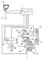
その概略構成と油圧制御装置を図2、図3に示す。
【0003】
プライマリプーリ16とセカンダリプーリ26の間にVベルト24を掛け渡した変速機構部10はロックアップクラッチ11を備えるトルクコンバータ12を介して図示しないエンジンに連結されている。
プライマリプーリ16は、トルクコンバータ12の出力軸と一体に回転する固定円錐板18と、これに対向する可動円錐板22とでV字状のプーリ溝を形成し、可動円錐板22の背面に油圧を及ぼし可動円錐板を軸方向に変位させる第1シリンダ室20を備えている。
セカンダリプーリ26は、図示しない車軸側への出力軸と一体に回転する固定円錐板30と、これに対向する可動円錐板34とでV字状のプーリ溝を形成している。可動円錐板34は図示しないリターンスプリングでプーリ溝の溝幅を狭める方向に付勢されるとともに、その背面に油圧を及ぼし可動円錐板34を軸方向に変位させる第2シリンダ室32を備えている。
【0004】
変速機構部10はCVTコントロールユニット1からの信号に基づいて油圧コントロールバルブ3により制御される。
第2シリンダ室32には油圧コントロールバルブ3からライン圧が常時供給され、第1シリンダ室20は油圧コントロールバルブの変速制御弁63に接続されている。
なお、第1シリンダ室20の受圧面積は第2シリンダ室32の受圧面積よりも大きく設定されている。
【0005】
第1シリンダ室20にかかる油圧が変速制御弁63により制御されてプライマリプーリ16の溝幅を変える一方、第2シリンダ室32へはライン圧が供給されて、Vベルト24に対する挟持圧力を制御するようになっている。これにより、Vベルト24と各プーリ16、26との接触摩擦力に応じて、駆動力の伝達がなされる。
これを回転数でみれば、プライマリプーリ16の溝幅を広げて、Vベルト24の接触半径が小でセカンダリプーリ26側の接触半径が大のプーリ比Low(低速側)のときには、変速比が大きくなってエンジン側回転数が減速されて車軸側へ出力されることとなる。逆のプーリ比Hi(高速側)では小さな変速比で出力される。この間、プライマリプーリ16とセカンダリプーリ26の接触半径比に対応して変速比が連続的に変化する。
【0006】
油圧コントロールバルブ3では、油圧ポンプ80からの油圧をライン圧レギュレータ60で調圧したライン圧が、第2シリンダ室32へ常時供給されるとともに、変速制御弁63へ供給される。第1シリンダ室20への油圧はライン圧を元圧として変速制御弁63がステップモータ64で駆動されることにより制御される。
油圧コントロールバルブ3は、さらにライン圧ソレノイド4、プレッシャモディファイヤ62、パイロット弁61を備える。
【0007】
CVTコントロールユニット1は、インヒビタスイッチ8からのセレクト位置信号に加え、スロットル開度センサ5からのスロットル開度(アクセルペダル開度)TV0およびエンジン回転数Neから推定したエンジントルクに基づいて必要なライン圧を求め、これに対応したデューティ比信号をライン圧ソレノイド4へ出力するとともに、変速指令をステップモータ64へ出力する。
ステップモータ64は例えば200ステップの範囲内で目標の変速比に対応して20〜170ステップの位置が選択されるようになっている。
【0008】
ライン圧ソレノイド4はパイロット弁61からの油圧をCVTコントロールユニット1からのデューティ比信号に応じてプレッシャモディファイヤ62側へ供給し、ライン圧レギュレータ60は油圧ポンプ80からの油圧をプレッシャモディファイヤ62から出力される油圧に応じたライン圧に設定する。ライン圧はこうして必要な伝達駆動力の大きさに応じて所定の範囲で変化されて出力される。
【0009】
変速制御弁63はプライマリプーリ16の可動円錐板22とステップモータ64間に掛け渡された変速リンク67の変位に応じてスプール63aが駆動され、ライン圧レギュレータ60からのライン圧を調整して第1シリンダ室20へ供給する。これにより、プライマリプーリ16の溝幅が可変制御されて所定の変速比が得られる。
CVTコントロールユニット1へは、プライマリプーリ16およびセカンダリプーリ26の各回転数を検出する第1回転数センサ6および第2回転数センサ7が接続され、これらの検出信号に基づいて変速機構部10における変速比が求められる。
上述のほか、図2および図3の全体構成の詳細は、特開平11−82725公報の記載を引用する。
【0010】
【発明が解決しようとする課題】
ところで、変速制御弁63および第2シリンダ室32へ供給されるライン圧は、両プーリ間での確実なトルク伝達を得られる値に設定する必要があるが、必要以上に大きなライン圧に設定すると、Vベルト24と各プーリ16、26との間の接触摩擦力による摩擦損失が大きくなり、燃費が悪化するという問題がある。
したがって、常にトルク伝達可能な最低限の油圧とするよう高精度にライン圧を制御するのが一般的である。
【0011】
しかしながら、例えばアクセル開度1/8程度の軽いアクセルペダル踏み込み状態において、容易にHi側への変速が達成されず途中で留まってしまうという現象が発生し、変速幅が実際上狭くなるという問題が生じる。
すなわち、変速機構部10において、通常現在の変速比が維持されるためには、プライマリプーリ16およびセカンダリプーリ26における各可動円錐板22、34の溝幅を狭める方向への推力の比が各シリンダ室の受圧面積に基づく所定の関係であることが必要で、プライマリプーリ16の推力がこの関係より低下すると変速比がLow側へ移行しやすくなる。
【0012】
上記プライマリプーリ16の推力はほとんど第1シリンダ室20への油圧によって決定されるが、セカンダリプーリ26側の推力は、第2シリンダ室32への油圧による推力のほかリターンスプリングおよびVベルト24による入力トルクに基づく推力が加わって形成されるため、アクセル開度1/8程度の伝達トルクが小さい状態では、ライン圧が極く低い値(通常最低油圧値)に設定され、上記シリンダ室の油圧が小さくなり、油圧以外の推力の影響が相対的に大きくなってしまい、上記推力関係を保てなくなる。
したがって本発明は、上記問題点に鑑み、Hi側への変速を設計通りに可能としながら、ベルト、プーリ間の摩擦損失を低減し、燃費性能を向上させる無段変速機の油圧制御装置を提供することを目的とする。
【0013】
【課題を解決するための手段】
請求項1の本発明は、それぞれ第1および第2シリンダ室が付設され油圧を供給されて溝幅を変更可能の1対の可変プーリと該可変プーリ間に掛け渡されたベルトからなる変速機構部と、ライン圧を生成し該ライン圧を第2シリンダ室へ常時供給するライン圧供給手段と、アクチュエータに駆動されてライン圧を元圧とした油圧を第1シリンダ室へ供給する変速制御弁と、運転状態に基づいてアクチュエータを制御する変速指令を出力するとともにライン圧供給手段が出力するライン圧を変化させる変速制御手段とを備える無段変速機の油圧制御装置において、変速制御手段が変速指令に対する変速達成状況を検出する変速達成検出手段を有し、変速制御弁で高速側への変速が達成されないときはライン圧供給手段によりライン圧を上昇させるものとした。
アクチュエータへ変速指令を出力しても目標通りに変速が達成されない場合はライン圧の値が上昇して変速が実現されるから、変速前の油圧は変速機構部における摩擦損失の少ない低い値に設定でき、変速が達成される限りその低い設定値が保持される。
【0014】
請求項2の発明は、とくにアクチュエータが目標変速比に対応する位置まで駆動されるステップモータを備え、変速制御手段は高速側への変速が達成されない場合に、ステップモータをさらに所定の付加ステップずつ駆動させ、変速が達成されないまま付加ステップ数があらかじめ定めた値に達したときにライン圧を上昇させるようにしたものである。
所定の付加ステップ数になるまでステップモータを駆動させても変速が達成されないことを確認してから、すなわち不感状態を確認してから油圧を上昇させるから、多少の応答遅れで直ちにライン圧を変動させることがなく、また、付加ステップ数が所定値に設定されて不感状態確認の時間も変動することがないから、安定した制御特性が得られる。
【0015】
請求項3の発明は、アクチュエータが目標変速比に対応する位置まで駆動されるステップモータを備え、変速制御手段は高速側への変速が達成されない場合に、ステップモータをさらに所定の付加ステップずつ駆動させ、変速が達成されないままステップモータの位置が最高速変速比に対応する位置に達したときにライン圧を上昇させるようにしたものである。
変速が達成されない場合直ちに油圧を上昇させず、付加ステップの駆動を行うから、請求項3の発明と同様に、多少の応答遅れでライン圧を変動させることがない。一方、付加ステップの駆動は最高速変速比に対応する位置に達するまで行うので、付加ステップ数をカウントする必要がなく演算負荷が軽減される。
【0016】
なお、各発明において、変速達成検出手段は、請求項4のように、1対の可変プーリ間の回転数比と目標変速比を比較して変速達成状況を検出するものとすることができる。
【0017】
また、請求項5の発明は、変速制御手段がライン圧を上昇させたあと変速達成検出手段により変速が達成されたことを検出したとき、さらにライン圧を上昇前のレベルに戻すものとしたものである。
変速が達成されたあと油圧を上昇前のレベルに戻すから、変速を達成するに必要な最小限の期間を除き、変速機構部に供給される油圧は常時摩擦損失の少ない値に維持される。
【0018】
【発明の実施の形態】
以下、本発明の実施の形態を実施例により説明する。
本実施例では、図2および図3に示した構成において、CVTコントロールユニット1によるライン圧の制御に際し、まず最低油圧を伝達トルクに見合った必要最小限の値である第1の設定値として制御を行うものとし、ステップモータ64を制御してHi側へ変速しようとしても目標の変速比が達成されないとき、最低油圧を第1の設定値よりも高い第2の設定値へ切替えるようにする。その他の構成は図2および図3に示したものと同じである。
【0019】
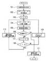
図1は、CVTコントロールユニット1における制御の流れと油圧コントロールバルブ3の作動を示すフローチャートである。
油圧コントロールバルブ3はそのライン圧レギュレータ60において、油圧ポンプ80からの油圧をCVTコントロールユニット1からの指令にしたがい、例えば0.6MPaとした第1の設定値の最低油圧から約4MPaの最大油圧の範囲で変化するライン圧として出力する。
なお、油圧ポンプ80、ライン圧ソレノイド4、プレッシャモディファイヤ62、、パイロット弁61およびライン圧レギュレータ60で発明のライン圧供給手段が構成されている。
【0020】
まずステップ101において、CVTコントロールユニット1で目標の変速比が決定される(変速開始)と、ステップ102で当該目標の変速比に対応したステップモータ64の標準のステップ位置が算出され、現在位置との差分のステップ数が変速指令としてステップモータ64へ出力される。なお、ここではHi側への変速を考える。
ステップ103では、後段の制御のための付加ステップ数をn=0に設定する。
【0021】
ステップ104ではステップモータ64が上記変速指令のステップ数だけ移動し、これにしたがって変速リンク67を介して変速制御弁63が作動し、プライマリプーリ16可動円錐板22の位置が変化してVベルト24の接触半径が変化する。
次のステップ105において、CVTコントロールユニット1では、第1回転数センサ6および第2回転数センサ7からプライマリプーリ16およびセカンダリプーリ26の各回転数を読み込み、実変速比を算出する。
【0022】
ステップ106では、その実変速比と目標の変速比とを比較して、変速が終了したかどうかをチェックする。そして、変速が終了していない、すなわち変速未達のときは、ステップ107へ進む。
ステップ107では、変速指令に対する付加ステップ数として、n=n+1とし、続いてステップ108において、付加ステップ数nが所定のしきい値(例えば15)を越えたかどうかをチェックする。
【0023】
ここで、n≦15であれば、ステップ109へ進み、CVTコントロールユニット1から1ステップ分の変速指令がステップモータ64へ出力されて、その後ステップ104へ戻る。
ステップ108のチェックでnが15を越えたときは、ステップ110へ進んで、CVTコントロールユニット1からライン圧ソレノイド4を通じて制御されるライン圧の最低油圧を第1の設定値から第2の設定値へ変更する補正を行ない、ステップ104へ戻る。
【0024】
なお、ステップ106のチェックで変速が終了したことが確認されたときには、ステップ111でライン圧の最低油圧を第1の設定値へ戻す処理を行って終了する。
【0025】
こうして、通常はライン圧の最低油圧を確実なトルク伝達を得るに必要な、第2の設定値より低い第1の設定値としておき、変速に際してステップモータ64が標準のステップ位置に基づいて駆動されても目標通りにHi側へ移行しないときは、さらにステップモータ64の駆動ステップ数を1ステップずつ増してゆくようにし、目標の変速比が達成された時点で制御が終了する。
【0026】
一方、付加ステップ数がしきい値に達するまで駆動ステップを増してもHi側へ移行しない不感状態が続いたら、最低油圧を第1の設定値より高い第2の設定値へ変更することにより、確実にHi側へ移行させる。これにより、目標の変速比に達すると、再びライン圧の最低油圧は第1の設定値へ戻される。
なお、上記のCVTコントロールユニット1が発明における変速制御手段を構成し、またCVTコントロールユニット1による上記制御フローにおけるステップ106が変速達成検出手段を構成している。
【0027】
実施例は以上のように構成され、ライン圧の最低油圧をベルト24、プーリ16、26間の摩擦損失が低減される第1の設定値とし、変速時にHi側への移行が達成されないときのみ最低油圧を第2の設定値へ高めて、変速ができた時点で再び第1の設定値へ戻すものとしたので、Hi側への移行が可能な限り最低油圧が第1の設定値に保持され、高い燃費性能が得られる。
【0028】
なお、上記実施例では、不感状態確認のためにしきい値に達するまで付加ステップ数の演算を行うようにしているが、演算を行うかわりに、付加ステップによる駆動を繰り返してステップモータ64が最高速変速比に対応する位置に達したときに、最低油圧を第2の設定値へ高めるようにしてもよい。これにより、CVTコントロールユニット1における演算負荷が軽減される。
【0029】
また、実施例は特開平11−82725公報に記載の装置をベースとして説明したが、本発明は変速機構部のプライマリプーリをトルクコンバータに直接連結した形態のエンジン駆動車両に限定されることなく、種々の形態の車両に適用することができる。
例えば、駆動源としてエンジンと電動モータを備えたハイブリッド車両においては、変速機構部を電動モータに連結して設置してもよい。
また、油圧コントロールバルブの油圧源もエンジン駆動による油圧ポンプに限らず、上記駆動源電動モータあるいは専用のモータで駆動される油圧ポンプを用いてもよい。
【0030】
【発明の効果】
以上のとおり、本発明は、それぞれシリンダ室が敷設された1対の可変プーリにベルトを掛け渡した変速機構部を備え、ライン圧を一方のシリンダ室に常時供給するとともに、アクチュエータに駆動される変速制御弁を介してライン圧を元圧とする油圧を他方のシリンダ室に供給して可変プーリの溝幅を変更し変速を行う無段変速機の油圧制御装置において、変速制御弁で高速側への変速が達成されないときはライン圧を上昇させるものとしたので、変速前の油圧は変速機構部における摩擦損失の少ない低い値に設定でき、確実に変速を実現しながら高い燃費性能が得られるという効果を有する。
【0031】
そして、とくにアクチュエータが目標変速比に対応する位置まで駆動されるステップモータを備え、高速側への変速が達成されない場合に、ステップモータをさらに所定の付加ステップずつ駆動させ、変速が達成されないまま付加ステップ数があらかじめ定めた値に達したときにライン圧を上昇させるようにすることにより、多少の応答遅れではライン圧を変動させることなく、安定した制御特性が得られる。
【0032】
あるいは、付加ステップ数があらかじめ定めた値に達したときにライン圧を上昇させるかわりに、所定の付加ステップずつ駆動させて、変速が達成されないままステップモータの位置が最高速変速比に対応する位置に達したときにライン圧を上昇させるようにすることによっても、同様に安定した制御特性が得られる。この場合、付加ステップ数をカウントする必要がなく演算負荷が軽減されるという利点を有している。
【0033】
また、ライン圧を上昇させたあと変速が達成されたことを検出したときには、さらにライン圧を上昇前のレベルに戻すものとすることにより、変速を達成するに必要な最小限の期間を除き、変速機構部に供給される油圧が常時摩擦損失の少ない値に維持されるので、一層燃費性能の向上が図れる。
【図面の簡単な説明】
【図1】本発明の実施例を示すCVTコントロールユニットにおける制御のフローチャートである。
【図2】本発明の適用対象を示すVベルト式無段変速機の概略構成を示す図である。
【図3】図2の無段変速機における油圧回路を示す図である。
【符号の説明】
1 CVTコントロールユニット
3 油圧コントロールバルブ
4 ライン圧ソレノイド
6 第1回転数センサ
7 第2回転数センサ
8 インヒビタスイッチ
10 変速機構部
12 トルクコンバータ
16 プライマリプーリ
18 固定円錐板
20 第1シリンダ室
22 可動円錐板
24 Vベルト
26 セカンダリプーリ
30 固定円錐板
32 第2シリンダ室
34 可動円錐板
60 ライン圧レギュレータ
61 パイロット弁
62 プレッシャモディファイヤ
63 変速制御弁
63a スプール
64 ステップモータ
67 変速リンク
80 油圧ポンプ[0001]
BACKGROUND OF THE INVENTION
The present invention relates to a continuously variable transmission using a V-belt for a vehicle or the like, and more particularly to an improvement in a hydraulic control device thereof.
[0002]
[Prior art]
As a continuously variable transmission suitable for a vehicle, for example, there is a V-belt continuously variable transmission as disclosed in JP-A-11-82725.
In this method, a V-belt is stretched between a primary pulley connected to the engine side and a secondary pulley connected to the axle side, and the groove width of the primary pulley is variably controlled by hydraulic pressure.
The schematic configuration and the hydraulic control apparatus are shown in FIGS.
[0003]
The
The
The
[0004]
The
Line pressure is always supplied from the
The pressure receiving area of the
[0005]
The hydraulic pressure applied to the
In terms of the number of rotations, when the groove width of the
[0006]
In the
The
[0007]
In addition to the select position signal from the
For example, the position of the
[0008]
The line pressure solenoid 4 supplies the hydraulic pressure from the
[0009]
The speed
The
In addition to the above, the details of the overall configuration of FIGS. 2 and 3 are cited from Japanese Patent Laid-Open No. 11-82725.
[0010]
[Problems to be solved by the invention]
By the way, the line pressure supplied to the
Therefore, it is common to control the line pressure with high accuracy so that the minimum oil pressure is always capable of transmitting torque.
[0011]
However, for example, in a light accelerator pedal depression state where the accelerator opening is about 1/8, there is a problem that the shift to the Hi side is not easily achieved, and the shift stops in the middle, and the shift width is actually narrowed. Arise.
That is, in order to maintain the current gear ratio in the
[0012]
The thrust of the
Therefore, in view of the above-described problems, the present invention provides a hydraulic control device for a continuously variable transmission that reduces friction loss between a belt and a pulley and improves fuel consumption performance while allowing shift to the Hi side as designed. The purpose is to do.
[0013]
[Means for Solving the Problems]
The first aspect of the present invention is a transmission mechanism comprising a pair of variable pulleys each having a first and a second cylinder chamber, supplied with hydraulic pressure and capable of changing the groove width, and a belt stretched between the variable pulleys. A line pressure supply means that generates a line pressure and constantly supplies the line pressure to the second cylinder chamber, and a shift control valve that is driven by an actuator and supplies a hydraulic pressure with the line pressure as an original pressure to the first cylinder chamber And a shift control unit that outputs a shift command for controlling the actuator based on the driving state and changes the line pressure output from the line pressure supply unit. a shift achieve detection means for detecting a gear shift progress with respect to the command, to increase the line pressureby the line pressure supply means when shifting to high-speed side is not achievedby the shift control valve It was the thing.
If the speed change is not achieved even if the speed change command is output to the actuator, the line pressure increases and the speed change is realized. Therefore, the hydraulic pressure before the speed change is set to a low value with little friction loss in the speed change mechanism. The low set value is maintained as long as the shift is achieved.
[0014]
The invention of claim 2 is provided with a step motor that drives the actuator to a position corresponding to the target gear ratio, and the shift control means further adds the step motor to each predetermined additional step when shifting to the high speed side is not achieved. Driven, the line pressure is increased when the number of additional steps reaches a predetermined value without shifting being achieved.
After confirming that shifting is not achieved even if the step motor is driven until the specified number of additional steps is reached, that is, after confirming the dead state, the hydraulic pressure is increased, so the line pressure immediately fluctuates with some response delay. In addition, since the number of additional steps is set to a predetermined value and the insensitive state confirmation time does not fluctuate, stable control characteristics can be obtained.
[0015]
According to a third aspect of the present invention, the actuator includes a step motor that is driven to a position corresponding to the target gear ratio, and the shift control means further drives the step motor by a predetermined additional step when shifting to the high speed side is not achieved. Thus, the line pressure is increased when the position of the step motor reaches a position corresponding to the highest speed gear ratio without achieving a shift.
If the shift is not achieved, the hydraulic pressure is not immediately increased and the additional step is driven, so that the line pressure is not fluctuated with a slight response delay as in the third aspect of the invention. On the other hand, since the driving of the additional step is performed until the position corresponding to the highest speed gear ratio is reached, it is not necessary to count the number of additional steps and the calculation load is reduced.
[0016]
In each invention, the shift achievement detecting means may detect the shift achievement status by comparing the rotation speed ratio between the pair of variable pulleys and the target gear ratio, as in claim 4.
[0017]
In the invention of
Since the hydraulic pressure is returned to the level before the increase after the shift is achieved, the hydraulic pressure supplied to the transmission mechanism unit is always maintained at a value with a small friction loss, except for the minimum period necessary to achieve the shift.
[0018]
DETAILED DESCRIPTION OF THE INVENTION
Hereinafter, embodiments of the present invention will be described by way of examples.
In the present embodiment, when the line pressure is controlled by the
[0019]
FIG. 1 is a flowchart showing a control flow in the
In the
The
[0020]
First, in
In
[0021]
In
In the
[0022]
In
In
[0023]
Here, if n ≦ 15, the routine proceeds to step 109 where a shift command for one step is output from the
When n exceeds 15 in the check of
[0024]
When it is confirmed in
[0025]
Thus, normally, the minimum hydraulic pressure of the line pressure is set as the first set value lower than the second set value necessary for obtaining reliable torque transmission, and the
[0026]
On the other hand, if the insensitive state that does not shift to the Hi side continues even if the drive step is increased until the number of additional steps reaches the threshold value, the minimum hydraulic pressure is changed to the second set value higher than the first set value, Make sure to shift to the Hi side. As a result, when the target gear ratio is reached, the minimum hydraulic pressure of the line pressure is returned to the first set value again.
The
[0027]
The embodiment is configured as described above, and the minimum line pressure is the first set value that reduces the friction loss between the
[0028]
In the above embodiment, the number of additional steps is calculated until the threshold value is reached to check the insensitive state. Instead of performing the calculation, the
[0029]
Further, although the embodiment has been described based on the device described in Japanese Patent Laid-Open No. 11-82725, the present invention is not limited to an engine-driven vehicle in which the primary pulley of the transmission mechanism unit is directly connected to the torque converter, The present invention can be applied to various types of vehicles.
For example, in a hybrid vehicle that includes an engine and an electric motor as drive sources, the speed change mechanism may be connected to the electric motor.
Further, the hydraulic source of the hydraulic control valve is not limited to the hydraulic pump driven by the engine, and a hydraulic pump driven by the drive source electric motor or a dedicated motor may be used.
[0030]
【The invention's effect】
As described above, the present invention includes a speed change mechanism portion in which a belt is stretched over a pair of variable pulleys each provided with a cylinder chamber, and the line pressure is constantly supplied to one cylinder chamber and is driven by an actuator. in the hydraulic control apparatus for a CVT in a hydraulic pressure source pressure to the line pressure through the shift control valve is supplied to the other cylinder chamber to change the groove width of the variable pulley performs a shift, the high-speed sidein the shift control valve Since the line pressure is increased when shifting to is not achieved, the hydraulic pressure before shifting can be set to a low value with little friction loss in the shifting mechanism, and high fuel efficiency can be obtained while reliably shifting. It has the effect.
[0031]
In particular, when the actuator is provided with a step motor that is driven to a position corresponding to the target gear ratio, and the shift to the high speed side is not achieved, the step motor is further driven by a predetermined additional step, and the shift is not achieved. By increasing the line pressure when the number of steps reaches a predetermined value, a stable control characteristic can be obtained without changing the line pressure with a slight response delay.
[0032]
Alternatively, instead of increasing the line pressure when the number of additional steps reaches a predetermined value, the step motor is driven by a predetermined number of additional steps, and the position of the step motor corresponds to the highest speed gear ratio without shifting being achieved. Similarly, stable control characteristics can be obtained by increasing the line pressure when the pressure reaches. In this case, it is not necessary to count the number of additional steps, and there is an advantage that the calculation load is reduced.
[0033]
In addition, when it is detected that the shift is achieved after increasing the line pressure, the line pressure is further returned to the level before the increase, except for the minimum period necessary to achieve the shift, Since the hydraulic pressure supplied to the transmission mechanism is always maintained at a value with little friction loss, the fuel efficiency can be further improved.
[Brief description of the drawings]
FIG. 1 is a flowchart of control in a CVT control unit according to an embodiment of the present invention.
FIG. 2 is a diagram showing a schematic configuration of a V-belt type continuously variable transmission showing an application target of the present invention.
FIG. 3 is a diagram showing a hydraulic circuit in the continuously variable transmission of FIG. 2;
[Explanation of symbols]
DESCRIPTION OF
Claims (5)
Translated fromJapaneseライン圧を生成し該ライン圧を第2シリンダ室へ常時供給するライン圧供給手段と、
アクチュエータに駆動されてライン圧を元圧とした油圧を第1シリンダ室へ供給する変速制御弁と、
運転状態に基づいてアクチュエータを制御する変速指令を出力するとともにライン圧供給手段が出力するライン圧を変化させる変速制御手段とを備える無段変速機の油圧制御装置において、
前記変速制御手段は、変速指令に対する変速達成状況を検出する変速達成検出手段を有し、前記変速制御弁で高速側への変速が達成されないときは前記ライン圧供給手段により前記ライン圧を上昇させることを特徴とする無段変速機の油圧制御装置。A transmission mechanism portion comprising a pair of variable pulleys each having a first and second cylinder chamber and supplied with hydraulic pressure to change the groove width, and a belt stretched between the variable pulleys;
Line pressure supply means for generating line pressure and constantly supplying the line pressure to the second cylinder chamber;
A shift control valve that is driven by an actuator and supplies a hydraulic pressure with a line pressure as an original pressure to the first cylinder chamber;
A hydraulic control device for a continuously variable transmission that includes a shift control unit that outputs a shift command for controlling the actuator based on an operating state and changes a line pressure output from the line pressure supply unit.
The shift control means has a shift achievement detecting means for detecting a shift achievement status with respect to a shift command, and when theshift control valve does not achieve a shift to the high speed side, theline pressure supply means increases the line pressure. A hydraulic control device for a continuously variable transmission.
前記変速制御手段は高速側への変速が達成されない場合に、前記ステップモータをさらに所定の付加ステップずつ駆動させ、変速が達成されないまま付加ステップ数があらかじめ定めた値に達したときに前記ライン圧を上昇させるものであることを特徴とする請求項1記載の無段変速機の油圧制御装置。The actuator includes a step motor that is driven to a position corresponding to a target gear ratio,
The shift control means further drives the step motor by a predetermined additional step when shifting to the high speed side is not achieved, and the line pressure when the number of additional steps reaches a predetermined value without achieving shifting. The hydraulic control device for a continuously variable transmission according to claim 1, wherein
前記変速制御手段は高速側への変速が達成されない場合に、前記ステップモータをさらに所定の付加ステップずつ駆動させ、変速が達成されないままステップモータの位置が最高速変速比に対応する位置に達したときに前記ライン圧を上昇させるものであることを特徴とする請求項1記載の無段変速機の油圧制御装置。The actuator includes a step motor that is driven to a position corresponding to a target gear ratio,
The shift control means further drives the step motor by a predetermined additional step when the shift to the high speed side is not achieved, and the position of the step motor reaches the position corresponding to the maximum speed ratio without achieving the shift. 2. The hydraulic control device for a continuously variable transmission according to claim 1, wherein the line pressure is sometimes increased.
Priority Applications (5)
| Application Number | Priority Date | Filing Date | Title |
|---|---|---|---|
| JP2000076792AJP3696474B2 (en) | 2000-03-17 | 2000-03-17 | Hydraulic control device for continuously variable transmission |
| US09/805,730US6547694B2 (en) | 2000-03-17 | 2001-03-14 | Hydraulic control system for a continuously variable transmission |
| DE10112794ADE10112794C2 (en) | 2000-03-17 | 2001-03-16 | Hydraulic control system for continuously variable transmissions |
| KR10-2001-0013625AKR100409410B1 (en) | 2000-03-17 | 2001-03-16 | Hydraulic control system for a continuously variable ransmission |
| FR0103591AFR2806455B1 (en) | 2000-03-17 | 2001-03-16 | HYDRAULIC CONTROL SYSTEM FOR VARIABLE TRANSMISSION CONTINUOUSLY |
Applications Claiming Priority (1)
| Application Number | Priority Date | Filing Date | Title |
|---|---|---|---|
| JP2000076792AJP3696474B2 (en) | 2000-03-17 | 2000-03-17 | Hydraulic control device for continuously variable transmission |
Publications (2)
| Publication Number | Publication Date |
|---|---|
| JP2001263474A JP2001263474A (en) | 2001-09-26 |
| JP3696474B2true JP3696474B2 (en) | 2005-09-21 |
Family
ID=18594474
Family Applications (1)
| Application Number | Title | Priority Date | Filing Date |
|---|---|---|---|
| JP2000076792AExpired - LifetimeJP3696474B2 (en) | 2000-03-17 | 2000-03-17 | Hydraulic control device for continuously variable transmission |
Country Status (5)
| Country | Link |
|---|---|
| US (1) | US6547694B2 (en) |
| JP (1) | JP3696474B2 (en) |
| KR (1) | KR100409410B1 (en) |
| DE (1) | DE10112794C2 (en) |
| FR (1) | FR2806455B1 (en) |
Families Citing this family (44)
| Publication number | Priority date | Publication date | Assignee | Title |
|---|---|---|---|---|
| JP4038353B2 (en) | 2001-09-12 | 2008-01-23 | ジヤトコ株式会社 | Hydraulic control device for belt type continuously variable transmission |
| KR100541912B1 (en)* | 2002-09-05 | 2006-01-10 | 쟈트코 가부시키가이샤 | V-Belt Type Continuously Variable Transmission |
| JP3905445B2 (en)* | 2002-09-12 | 2007-04-18 | ジヤトコ株式会社 | Hydraulic control device for V-belt type continuously variable transmission |
| US7011600B2 (en) | 2003-02-28 | 2006-03-14 | Fallbrook Technologies Inc. | Continuously variable transmission |
| JP2004263737A (en)* | 2003-02-28 | 2004-09-24 | Jatco Ltd | Shift control device for continuously variable transmission |
| JP4220443B2 (en)* | 2004-08-06 | 2009-02-04 | ジヤトコ株式会社 | Cooling structure of actuator for shift control |
| WO2006041718A2 (en) | 2004-10-05 | 2006-04-20 | Fallbrook Technologies, Inc. | Continuously variable transmission |
| JP4309389B2 (en) | 2005-10-04 | 2009-08-05 | ジヤトコ株式会社 | Line pressure control device for continuously variable transmission |
| WO2007070167A2 (en) | 2005-10-28 | 2007-06-21 | Fallbrook Technologies Inc. | Electromotive drives |
| PL1954959T3 (en) | 2005-11-22 | 2013-10-31 | Fallbrook Ip Co Llc | Continuously variable transmission |
| CN102221073B (en) | 2005-12-09 | 2013-03-27 | 福博科技术公司 | Continuously variable transmission |
| EP1811202A1 (en) | 2005-12-30 | 2007-07-25 | Fallbrook Technologies, Inc. | A continuously variable gear transmission |
| CN102269055B (en) | 2006-06-26 | 2013-08-28 | 福博科技术公司 | Continuously variable transmission |
| JP4699970B2 (en)* | 2006-09-22 | 2011-06-15 | ジヤトコ株式会社 | Line pressure control device for belt type continuously variable transmission |
| US7693638B2 (en)* | 2007-01-23 | 2010-04-06 | Gm Global Technology Operations, Inc. | Commanded clutch diagnostic for hybrid vehicles |
| EP2125469A2 (en) | 2007-02-01 | 2009-12-02 | Fallbrook Technologies Inc. | System and methods for control of transmission and/or prime mover |
| US20100093479A1 (en) | 2007-02-12 | 2010-04-15 | Fallbrook Technologies Inc. | Continuously variable transmissions and methods therefor |
| TWI461615B (en) | 2007-02-16 | 2014-11-21 | Fallbrook Ip Co Llc | Infinitely variable transmissions, continuously variable transmissions, methods, assemblies, subassemblies, and components therefor |
| EP2142826B1 (en) | 2007-04-24 | 2015-10-28 | Fallbrook Intellectual Property Company LLC | Electric traction drives |
| US8641577B2 (en) | 2007-06-11 | 2014-02-04 | Fallbrook Intellectual Property Company Llc | Continuously variable transmission |
| CN103697120B (en) | 2007-07-05 | 2017-04-12 | 福博科技术公司 | Continuously variable transmission |
| CN103939602B (en) | 2007-11-16 | 2016-12-07 | 福博科知识产权有限责任公司 | Controllers for variable speed drives |
| US8321097B2 (en) | 2007-12-21 | 2012-11-27 | Fallbrook Intellectual Property Company Llc | Automatic transmissions and methods therefor |
| US8313405B2 (en) | 2008-02-29 | 2012-11-20 | Fallbrook Intellectual Property Company Llc | Continuously and/or infinitely variable transmissions and methods therefor |
| US8317651B2 (en) | 2008-05-07 | 2012-11-27 | Fallbrook Intellectual Property Company Llc | Assemblies and methods for clamping force generation |
| CN102112778B (en) | 2008-06-06 | 2013-10-16 | 福博科技术公司 | Infinitely variable transmission, continuously variable transmission, methods, assemblies, subassemblies and components therefor |
| EP2304272B1 (en) | 2008-06-23 | 2017-03-08 | Fallbrook Intellectual Property Company LLC | Continuously variable transmission |
| CA2732668C (en) | 2008-08-05 | 2017-11-14 | Fallbrook Technologies Inc. | Methods for control of transmission and prime mover |
| US8469856B2 (en) | 2008-08-26 | 2013-06-25 | Fallbrook Intellectual Property Company Llc | Continuously variable transmission |
| US8167759B2 (en) | 2008-10-14 | 2012-05-01 | Fallbrook Technologies Inc. | Continuously variable transmission |
| ES2439647T3 (en) | 2009-04-16 | 2014-01-24 | Fallbrook Intellectual Property Company Llc | Stator set and speed change mechanism for a continuously variable transmission |
| US8512195B2 (en) | 2010-03-03 | 2013-08-20 | Fallbrook Intellectual Property Company Llc | Infinitely variable transmissions, continuously variable transmissions, methods, assemblies, subassemblies, and components therefor |
| US8888643B2 (en) | 2010-11-10 | 2014-11-18 | Fallbrook Intellectual Property Company Llc | Continuously variable transmission |
| CN104011436B (en)* | 2011-12-13 | 2016-03-02 | 加特可株式会社 | The controlling method of stepless speed variator and stepless speed variator |
| CN104302949B (en) | 2012-01-23 | 2017-05-03 | 福博科知识产权有限责任公司 | Infinitely variable continuously variable transmission, continuously variable continuously variable transmission, method, assembly, subassembly, and parts thereof |
| KR102433297B1 (en) | 2013-04-19 | 2022-08-16 | 폴브룩 인텔렉츄얼 프로퍼티 컴퍼니 엘엘씨 | Continuously variable transmission |
| JP6262052B2 (en)* | 2014-03-27 | 2018-01-17 | ジヤトコ株式会社 | Control device for continuously variable transmission |
| US10400872B2 (en) | 2015-03-31 | 2019-09-03 | Fallbrook Intellectual Property Company Llc | Balanced split sun assemblies with integrated differential mechanisms, and variators and drive trains including balanced split sun assemblies |
| US10047861B2 (en) | 2016-01-15 | 2018-08-14 | Fallbrook Intellectual Property Company Llc | Systems and methods for controlling rollback in continuously variable transmissions |
| KR102364407B1 (en) | 2016-03-18 | 2022-02-16 | 폴브룩 인텔렉츄얼 프로퍼티 컴퍼니 엘엘씨 | continuously variable transmission system and method |
| US10023266B2 (en) | 2016-05-11 | 2018-07-17 | Fallbrook Intellectual Property Company Llc | Systems and methods for automatic configuration and automatic calibration of continuously variable transmissions and bicycles having continuously variable transmissions |
| US11215268B2 (en) | 2018-11-06 | 2022-01-04 | Fallbrook Intellectual Property Company Llc | Continuously variable transmissions, synchronous shifting, twin countershafts and methods for control of same |
| WO2020176392A1 (en) | 2019-02-26 | 2020-09-03 | Fallbrook Intellectual Property Company Llc | Reversible variable drives and systems and methods for control in forward and reverse directions |
| JP7153628B2 (en) | 2019-11-12 | 2022-10-14 | 本田技研工業株式会社 | hydraulic controller |
Family Cites Families (9)
| Publication number | Priority date | Publication date | Assignee | Title |
|---|---|---|---|---|
| JPS60104847A (en)* | 1983-11-11 | 1985-06-10 | Toyota Motor Corp | Line pressure control device for continuously variable transmission for automobiles |
| JPS6353129A (en)* | 1986-08-20 | 1988-03-07 | Fuji Heavy Ind Ltd | Control device for speed change ratio of continuously variable transmission |
| JPH0571627A (en)* | 1991-09-09 | 1993-03-23 | Hitachi Ltd | Controller of automatic transmission for vehicle |
| JPH08219244A (en)* | 1995-02-14 | 1996-08-27 | Unisia Jecs Corp | Controller for continuously variable transmission |
| JP3475639B2 (en)* | 1996-03-07 | 2003-12-08 | 日産自動車株式会社 | Transmission control device for continuously variable transmission |
| JP3446460B2 (en)* | 1996-03-13 | 2003-09-16 | 日産自動車株式会社 | Transmission control device for continuously variable transmission |
| JP3248615B2 (en)* | 1997-01-24 | 2002-01-21 | 愛知機械工業株式会社 | Cylinder structure for pulley of belt type continuously variable transmission |
| JP3430874B2 (en)* | 1997-08-29 | 2003-07-28 | 日産自動車株式会社 | Hydraulic control device for continuously variable transmission |
| DE19908250A1 (en)* | 1999-02-25 | 2000-08-31 | Zahnradfabrik Friedrichshafen | Transmission ratio regulation for continuous automatic gearbox involves correction element taking account of internal and external system parameters in physical mathematical model |
- 2000
- 2000-03-17JPJP2000076792Apatent/JP3696474B2/ennot_activeExpired - Lifetime
- 2001
- 2001-03-14USUS09/805,730patent/US6547694B2/ennot_activeExpired - Lifetime
- 2001-03-16KRKR10-2001-0013625Apatent/KR100409410B1/ennot_activeExpired - Fee Related
- 2001-03-16DEDE10112794Apatent/DE10112794C2/ennot_activeExpired - Fee Related
- 2001-03-16FRFR0103591Apatent/FR2806455B1/ennot_activeExpired - Fee Related
Also Published As
| Publication number | Publication date |
|---|---|
| FR2806455A1 (en) | 2001-09-21 |
| JP2001263474A (en) | 2001-09-26 |
| DE10112794A1 (en) | 2001-09-27 |
| DE10112794C2 (en) | 2003-05-28 |
| US20010023217A1 (en) | 2001-09-20 |
| FR2806455B1 (en) | 2006-01-06 |
| US6547694B2 (en) | 2003-04-15 |
| KR100409410B1 (en) | 2003-12-18 |
| KR20010090468A (en) | 2001-10-18 |
Similar Documents
| Publication | Publication Date | Title |
|---|---|---|
| JP3696474B2 (en) | Hydraulic control device for continuously variable transmission | |
| JP5435137B2 (en) | Control device for continuously variable transmission for vehicle | |
| JP4593486B2 (en) | Shift control device for belt type continuously variable transmission | |
| JP4072200B2 (en) | Control device for belt type continuously variable transmission | |
| JP4038097B2 (en) | Hydraulic sensor fail control device for belt type continuously variable transmission | |
| JP2004124965A (en) | Controller for belt type continuously variable transmission | |
| JP3905445B2 (en) | Hydraulic control device for V-belt type continuously variable transmission | |
| JP4070739B2 (en) | Continuously variable transmission | |
| US10683928B2 (en) | Transmission control device and transmission control method | |
| EP3273108A1 (en) | Transmission control device and transmission control method | |
| JP4124625B2 (en) | Control device for continuously variable transmission | |
| EP3273104A1 (en) | Transmission control device and transmission control method | |
| EP3273109A1 (en) | Transmission control device and transmission control method | |
| JP4553549B2 (en) | Control device for belt type continuously variable transmission | |
| JP3944042B2 (en) | Hydraulic pressure reduction rate limiting device for V-belt type continuously variable transmission | |
| JP3718405B2 (en) | Hydraulic control device for continuously variable transmission | |
| JP2008106813A (en) | Hydraulic control device of belt continuously variable transmission for vehicle | |
| KR100557372B1 (en) | Line pressure controlling device in continously variable transmission | |
| JP4101563B2 (en) | Slip prevention device for continuously variable transmission for vehicle | |
| JP4346879B2 (en) | Hydraulic control device for automatic transmission for vehicle | |
| JP2003083430A (en) | Hydraulic controller for belt type continuously variable transmission | |
| EP3273107A1 (en) | Transmission control device and transmission control method | |
| JP2004068900A (en) | Variable speed actuator controlling device in continuously variable transmission | |
| JP2004263737A (en) | Shift control device for continuously variable transmission | |
| JP2001263470A (en) | Hydraulic control device for transmission |
Legal Events
| Date | Code | Title | Description |
|---|---|---|---|
| A977 | Report on retrieval | Free format text:JAPANESE INTERMEDIATE CODE: A971007 Effective date:20041109 | |
| A131 | Notification of reasons for refusal | Free format text:JAPANESE INTERMEDIATE CODE: A131 Effective date:20041130 | |
| A521 | Request for written amendment filed | Free format text:JAPANESE INTERMEDIATE CODE: A523 Effective date:20050125 | |
| TRDD | Decision of grant or rejection written | ||
| A01 | Written decision to grant a patent or to grant a registration (utility model) | Free format text:JAPANESE INTERMEDIATE CODE: A01 Effective date:20050628 | |
| A61 | First payment of annual fees (during grant procedure) | Free format text:JAPANESE INTERMEDIATE CODE: A61 Effective date:20050629 | |
| R150 | Certificate of patent or registration of utility model | Ref document number:3696474 Country of ref document:JP Free format text:JAPANESE INTERMEDIATE CODE: R150 Free format text:JAPANESE INTERMEDIATE CODE: R150 | |
| FPAY | Renewal fee payment (event date is renewal date of database) | Free format text:PAYMENT UNTIL: 20080708 Year of fee payment:3 | |
| FPAY | Renewal fee payment (event date is renewal date of database) | Free format text:PAYMENT UNTIL: 20090708 Year of fee payment:4 | |
| FPAY | Renewal fee payment (event date is renewal date of database) | Free format text:PAYMENT UNTIL: 20090708 Year of fee payment:4 | |
| FPAY | Renewal fee payment (event date is renewal date of database) | Free format text:PAYMENT UNTIL: 20100708 Year of fee payment:5 | |
| FPAY | Renewal fee payment (event date is renewal date of database) | Free format text:PAYMENT UNTIL: 20100708 Year of fee payment:5 | |
| FPAY | Renewal fee payment (event date is renewal date of database) | Free format text:PAYMENT UNTIL: 20110708 Year of fee payment:6 | |
| FPAY | Renewal fee payment (event date is renewal date of database) | Free format text:PAYMENT UNTIL: 20110708 Year of fee payment:6 | |
| FPAY | Renewal fee payment (event date is renewal date of database) | Free format text:PAYMENT UNTIL: 20120708 Year of fee payment:7 | |
| FPAY | Renewal fee payment (event date is renewal date of database) | Free format text:PAYMENT UNTIL: 20120708 Year of fee payment:7 | |
| FPAY | Renewal fee payment (event date is renewal date of database) | Free format text:PAYMENT UNTIL: 20130708 Year of fee payment:8 | |
| FPAY | Renewal fee payment (event date is renewal date of database) | Free format text:PAYMENT UNTIL: 20130708 Year of fee payment:8 | |
| FPAY | Renewal fee payment (event date is renewal date of database) | Free format text:PAYMENT UNTIL: 20140708 Year of fee payment:9 | |
| R250 | Receipt of annual fees | Free format text:JAPANESE INTERMEDIATE CODE: R250 | |
| EXPY | Cancellation because of completion of term |