JP3694612B2 - Reflective type liquid crystal display device and apparatus equipped with the same - Google Patents
Reflective type liquid crystal display device and apparatus equipped with the sameDownload PDFInfo
- Publication number
- JP3694612B2 JP3694612B2JP13855599AJP13855599AJP3694612B2JP 3694612 B2JP3694612 B2JP 3694612B2JP 13855599 AJP13855599 AJP 13855599AJP 13855599 AJP13855599 AJP 13855599AJP 3694612 B2JP3694612 B2JP 3694612B2
- Authority
- JP
- Japan
- Prior art keywords
- liquid crystal
- crystal display
- light
- display device
- display surface
- Prior art date
- Legal status (The legal status is an assumption and is not a legal conclusion. Google has not performed a legal analysis and makes no representation as to the accuracy of the status listed.)
- Expired - Fee Related
Links
Images


Landscapes
- Liquid Crystal (AREA)
- Devices For Indicating Variable Information By Combining Individual Elements (AREA)
Description
Translated fromJapanese【0001】
【発明の属する技術分野】
本発明は、反射型液晶表示装置及びそれを備えた携帯ゲーム機、携帯情報端末、モバイルコンピュータなどの機器に関するものである。
【0002】
【従来技術】
一般に、液晶表示装置は、CRT(Cathode Ray Tube)、PDP(Plasma Display Panel)等の自発光型のディスプレイと異なり、光の透過光量を調節することで画像を表示する非発光型のディスプレイである。液晶表示装置は、大別すると透過型と反射型とに分類できる。
【0003】
透過型の液晶表示装置は、表示面の背面側に照明装置を備え、照明装置からの照明光により、その表示画像の視認性を高めている。
【0004】
一方、反射型の液晶表示装置は、液晶層の裏面側に反射部を設け、周囲光を利用して表示を行うものであり、明るい環境下では特定の光源を必要とせず、消費電力を小さくできるという特長がある。特に直射日光の当たるような非常に明るい場所では、発光型ディスプレイや透過型液晶表示装置では表示面表面での外光反射等により表示がほとんど見えなくなるのに対して反射型液晶表示装置ではより鮮明に見えるといった利点もある。
【0005】
このため、反射型液晶表示装置は、低消費電力化が望まれる携帯情報端末やモバイルコンピューター等の携帯機器、或いは野外での使用が想定されるデジタルカメラ等へ採用されている。
【0006】
しかし、反射型液晶表示装置は、周囲光を利用して表示を行うため、暗い環境下ではその視認性が悪くなり、特に夜間などの暗闇では表示が全く認識できなくなるという課題を有する。このため、反射型液晶表示装置、及び表示部として反射型液晶表示装置を備える機器では十分な周囲光が得られない場合に備えて何らかの補助照明装置が望まれる。
【0007】
このような照明装置として従来から様々な照明装置が提案されている。
従来から提案されている照明装置は、大別すると、反射型液晶表示装置の表示面全面を覆うように配置した透明な導光体と導光体の端部に配置した光源とから構成され光源からの出射光を導光体を介して表示面に照射するようにした照明装置(以下、導光体式前方照明装置)と、反射型液晶表示装置の前方であって表示面から離れた場所に光源を配置して光源光を直接表示面に照射するようにした照明装置(以下、投射式前方照明装置)とがある。
【0008】
導光体式前方照明装置は、例えばSID 95 DIGEST p375-378、特開平5-158034号公報、特開平10-142601号公報等に開示されている。いずれも、導光体の端部に配置した光源からの出射光を導光体に導入し、導光体内を伝播する光のうち導光体の表面、もしくは裏面に形成した突起部、或いはプリズム部(傾斜部)に入射した光が液晶表示装置の表示面に向かって出射し、照明するように構成したものである。
【0009】
また、投射式前方照明装置を備える表示装置、或いは機器は例えば特開平4-70626号公報、特開平9-211448号公報、特開平10-246886号公報等に開示されている。いずれも反射型液晶表示装置を備える機器本体、或いは機器本体に設けられた支柱、或いは表示部を覆うための蓋部等に光源を設け、前方から表示部を直接照明するようにしたものである。
【0010】
このような照明装置を有する反射型液晶表示装置を備えた機器では、明るい環境下では照明装置を使用せずに外光のみで表示をみることができ、周囲の照明が暗い場合には照明装置を使用することで良好な視認性を確保するものである。
【0011】
【発明が解決しようとする課題】
導光体式前方照明装置は、光源からの出射光を導光体に入射させる際の光損失や、導光体内を伝播する光の反射型液晶表示装置と異なる方向への漏れ等により光源光の利用効率が60%以下と低く、照明装置利用時に消費電力が大きくなるという問題がある。
【0012】
さらに導光体内を伝播する光を液晶表示装置側へ向かわせる為の溝やマイクロプリズムといった構造体が表示面上に存在することになるため表示を劣化させるといった問題もある。
【0013】
また、反射型液晶表示装置の前面にタッチパネルを設けた機器では表示面上に導光体があると、その厚みのために入力用ペンで指示した位置と、液晶表示装置の表示との間に大きな視差(ずれ)が生じて使い勝手が悪くなるといった問題がある。
【0014】
一方、投射式前方照明装置では導光体等の光損失の原因となるような複雑な光学系を必要としないため効率の良い照明が期待できる。さらに表示面上に導光体等の付加部材を配置しないため、表示の劣化や、タッチパネル使用時の視差といった導光体式前方照明装置特有の課題が回避できる。
【0015】
しかし、投写式前方照明装置では照明装置を機器本体に備える場合、照明装置と反射型液晶表示装置との距離が十分に離せないため、反射型液晶表示装置の表示面を均一に照明することが困難である。つまり、表示面の位置により光源(或いは光出射部)からの距離や、光源と表示面との成す角度(光源と表示面とを結ぶ線の角度)が異なるので照明装置からの照明光の強さや、光入射角度は液晶表示装置の表示面の位置毎に異なり、表示面を均一に照明することができず、表示面内で均一な明るさの表示を得ることが困難という課題がある。
【0016】
また、投写式前面照明装置では明るい表示が得られる方向と照明光の反射型液晶表示装置の表示部表面での界面反射の方向とが一致するため、明るい表示を得ようとすると照明装置の光出射部が映り込んで表示が見にくくなるという課題がある。
【0017】
さらに、反射型液晶表示装置として偏光板を2枚用い、反射部をその裏面に外付けした場合は照明光が斜めに入射すると「暗表示部の影」が生じるという課題がある。ここで、「暗表示部の影」とは 暗表示部と隣接する明表示部の輝度が低下する現象で、あたかも暗表示部の影が写っているように見える現象をいう。
【0018】
本発明の目的は、表示の劣化、タッチパネル使用時の視差、及び光源や照明装置の映り込みがなく、明るく、かつ均一な表示が得られる反射型液晶表示装置及びそれを備えた機器を提供することにある。
【0019】
【課題を解決するための手段】
上記目的を達成するために、本発明は、所定の間隙を介して接合され少なくとも一方が透明な一対の基板と、前記一対の基板間に備えられた液晶層と、該液晶層の背面側に設けられた反射手段とを有する反射型液晶表示装置において、前記反射手段は反射面を有し、該反射面の角度は表示面内で連続的に変化しており、さらに前記反射手段は前記反射面の正反射成分の大きさが表示面下部から表示面上部に向かって連続的に小さくなるように構成されていることを特徴とする。
【0020】
また、本発明は、所定の間隙を介して接合され少なくとも一方が透明な一対の基板と、前記一対の基板間に備えられた液晶層と、該液晶層の背面側に設けられた反射手段とを有し、かつ表示面に照明光を照射する照明装置を備えた反射型液晶表示装置において、前記照明装置は、前記表示面の前方に配置され、かつ前記表示面の垂線方向と異なる方向から前記表示面を照明する光出射部を有し、前記反射手段は反射面を有し、該反射面の角度は表示面内で連続的に変化しており、さらに前記反射手段は前記反射面の正反射成分の大きさが表示面下部から表示面上部に向かって連続的に小さくなるように構成されていることを特徴とする。
【0021】
上記構成により、本発明の反射型液晶表示装置は、導光体等の光損失の原因となるような複雑な光学系を必要としないため、光損失の少ない効率の良い照明ができる。
【0022】
また、反射型液晶表示装置の表示面上に導光体等の付加部材を配置しないため、付加部材による表示の劣化のない見やすい画像が得られ、視差の少ない自然なペン入力が可能になる。
【0023】
さらに、反射型液晶表示装置の反射手段は反射面を有し、その反射面の角度は表示面内で連続的に変化しており、さらに反射手段は反射面の正反射成分の大きさが表示面下部から表示面上部に向かって連続的に小さくなるように構成されている。すなわち、反射型液晶表示装置の反射手段は、その反射角度や指向性を表示面の各位置における照明光の光入射角度や、強さに応じて最適化しており、所定の位置に配置した照明装置から出射し、表示面に斜めに入射する照明光を観察者側へ均一に反射するように構成するので、明るく面内の均一性が高い表示が得られる。 この際、反射型液晶表示装置の表面等の界面での正反射光の方向と、画像光の方向は異なるため、照明装置の像が観察されて画質が劣化することがない。
【0024】
前記反射型液晶表示装置の反射手段としては、大別して以下の3つの反射手段を用いることができる。
【0025】
▲1▼表示面に対して傾斜した複数の反射面と、反射面で反射した光を拡散させる光拡散手段とから構成する反射手段。
【0026】
(2)複数の凹部、または複数の凸部、または複数の凹凸部が形成された反射面を有し、各凹部、または各凸部、または各凹凸部は、少なくとも一つの非対称軸を有する断面形状と、一つの対称軸を有する円弧部を含む平面形状とを有し、対称軸は、入射する光の主光束の方位角方向と平行となるように設定した反射手段。
【0027】
▲3▼ホログラムからなる反射手段。
【0028】
また、本発明の他の特徴は、前記照明装置から斜めに入射する照明光に対して、暗表示の透過率が高くなるように、前記表示面側の基板の前面に偏光板と位相差板とを配置し、前記反射手段と前記反射手段側の基板との間に偏光板を配置し、かつ前記表示面側の偏光板の吸収軸の方位角は255°、前記位相差板の遅相軸の方位角は185°、前記表示面側の基板側の液晶配向軸の方位角は105°、前記反射手段側の基板側の液晶配向軸の方位角は165°、前記反射手段側の偏光板の吸収軸の方位角は120°であることにある。
【0029】
上記構成により、表示面に斜めに入射する照明光が暗表示部を通過しても、透過率が高いため、隣接する明表示部に現れる「暗表示部の影」の発生が解消され、視認性のよい画像が得られる。
【0030】
また、本発明の他の特徴は、前記一対の基板のうち前記液晶層の背面側に位置する基板と、前記液晶層との間に、前記反射手段を備えたことにある。
【0031】
この場合は、反射型液晶表示装置に入射した照明光が液晶層を通過し、反射手段で反射して再び液晶層を通過して反射型液晶表示装置から出射する際の往路復路での位置のずれが小さいので、照明光が斜め入射するために生じる画質の劣化が抑えられて、明るく、色純度の高い表示ができる。
【0032】
また、本発明の他の特徴は、前記表示面側の基板の前面に偏光板が配置され、前記反射型液晶表示装置が高い反射率、高いコントラスト比が得られる光の入射方向と、前記照明装置からの照明光の入射方向とが略一致するように構成されていることにある
つまり、前記単偏光板の反射型液晶表示装置は、所定の位置に配置した照明装置からの照明光に対して、反射率や、コントラスト比が高くなる表示モードや条件とすることで、照明装置使用時には外光を利用する場合よりも高品位な画質が得られる。
【0033】
また、本発明の他の特徴は、前記照明装置の光出射部を、前記反射型液晶表示装置の上方に配置されることにある。
【0034】
これにより、以下の効果が得られる。つまり、反射型液晶表示装置は周囲が明るい環境下では照明装置を使用することなく外光のみでの使用が可能である。この際、外光の大部分は反射型液晶表示装置の上方から入射する。特にキーボードを有する機器では反射型液晶表示装置の下方から外光が入射することは少なく、外光の大部分は液晶表示装置の上方から入射する。
【0035】
従って、照明装置使用時の照明装置の配置位置を液晶表示装置の上部とし、上方から入射する光に対応した反射部を構成することで照明装置不使用時に反射型液晶表示装置の上方から入射する外光が効率よく観察者側へ反射されるので明るい画像が得られるという効果がある。
【0036】
さらに暗闇の中で作業する場合は、上部に配置した照明装置からの照明光のうち反射型液晶表示装置の表面等で反射した光がキーボードや手元を照明することになり作業性が上がるという効果もある。
【0037】
また、本発明の他の特徴は、前記光出射部は、前記反射型液晶表示装置の横幅と同等、或いはそれ以上の横幅を有し、前記表示面の前方で、かつ上方、或いは下方に配置されることにある。
【0038】
また、本発明の他の特徴は、前記表示面側の基板と前記液晶層との間にカラーフィルタを配置し、前記前記照明装置からの照明光の主光束の方位角方向と平行となる方向へ連続的に形成したことにある。
【0039】
ここで、照明装置から出射した照明光は、さまざまな角度で反射型液晶表示装置に入射する。そこで、照明光の強度がもっとも強い方向の光をここでは以下、照明光の主光束(の方向)と呼ぶことにする。
【0040】
上記の通り、反射型液晶表示装置に配置されるカラーフィルタを、照明装置からの照明光の主光束の入射方向の方位角方向と平行となる方向に連続的に形成すれば、照明光は反射型液晶表示装置に斜めに入射し、反射手段で反射する照明光の一部が往路復路の行程で異なる色のカラーフィルターを通過し、吸収されることが抑制されるので、より明るく、色純度の高い画像が得られるという効果がある。
【0041】
また、本発明は、入射する光の反射光量を変調し画像として出力する反射型液晶表示装置と、該反射型液晶表示装置の表示面に照明光を照射する照明装置と、前記反射型液晶表示装置及び前記照明装置を制御する機器本体と、該機器本体に設けられ前記照明装置を支持する可動支持部とを備えた機器において、前記反射型液晶表示装置は、所定の間隙を介して接合され少なくとも一方が透明な一対の基板と、前記一対の基板間に備えられた液晶層と、該液晶層の背面側に設けられた反射手段とを有し、前記反射手段は反射面を有し、該反射面の角度は表示面内で連続的に変化しており、さらに前記反射手段は前記反射面の正反射成分の大きさが表示面下部から表示面上部に向かって連続的に小さくなるように構成されており、前記照明装置は、前記表示面の垂線方向と異なる方向から前記表示面を照明する光出射部を有し、かつ前記可動支持部を介して前記表示面の前方に可動可能に配置されることを特徴とする。
【0042】
また、本発明は、入射する光の反射光量を変調し画像として出力する反射型液晶表示装置と、該反射型液晶表示装置の表示面に照明光を照射する照明装置と、前記反射型液晶表示装置及び前記照明装置を制御する機器本体とを備えた機器において、前記反射型液晶表示装置は、所定の間隙を介して接合され少なくとも一方が透明な一対の基板と、前記一対の基板間に備えられた液晶層と、該液晶層の背面側に設けられた反射手段とを有し、前記反射手段は反射面を有し、該反射面の角度は表示面内で連続的に変化しており、さらに前記反射手段は前記反射面の正反射成分の大きさが表示面下部から表示面上部に向かって連続的に小さくなるように構成されており、前記照明装置は、前記表示面の垂線方向と異なる方向から前記表示面を照明する光出射部を有し、かつ前記機器本体に着脱可能に配置されることを特徴とする。
【0043】
上記構成により、明るい環境下では機器に備える照明装置を使用せずに外光のみで表示をみることができ、周囲の照明が暗い場合には機器に備えた照明装置を使用することで良好な視認性を確保できる。このため、周囲の環境によらずいつでも良好な視認性を確保できるとともに、必要な場合にのみ照明装置を用いることで機器全体の消費電力が低減できるという効果がある。
【0044】
【発明の実施の形態】
以下、本発明の一実施の形態例に係わる反射型液晶表示装置及びそれを備えた機器を、図面を参照しながら説明する。
【0045】
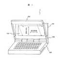
図1は、本発明の一実施の形態例に係わる反射型液晶表示装置、およびそれを備えた携帯情報機器の斜視図である。この機器1は、キーボード等の入力手段や、CPU、信号処理回路等を筐体内に備える本体部300と、本体部300に蝶番構造により取付けられた開閉自在な蓋部500と、蓋部500に備えられた反射型液晶表示装置100と、本体部300に可動支持部400を介して備え付けられた照明装置200とから構成される。
【0046】
反射型液晶表示装置100の表面には図示しないタッチパネルを備えるようにしても良い。タッチパネルとしては抵抗膜タイプのタッチパネルを用いることができる。抵抗膜タイプのタッチパネルは、表面に透明な導電加工を施した透明な高分子フィルムからなる上部電極基板と、同様な導電加工を施した透明基板からなる下部電極基板とを導電面側を対向するようにスペーサーを介して貼りあわせた構造となっており、上部電極の上からポリアセタール等からなる入力用ペンで押すと2枚の電極基板の電極が接触してスイッチがONとなる仕組みのものである。
【0047】
このタイプのタッチパネルには、マトリクスタイプとアナログタイプとがある。マトリクスタイプは、上部電極基板及び下部電極基板に形成されたストライプ状の透明電極を互いに直交するように配置し、その交差部を独立したスイッチとして機能させるものである。このタイプでは電極パターンと反射型液晶表示装置100の画素との関係でモアレが生じ易いので、電極のピッチや、ストライプ電極の方向等に工夫が必要である。
【0048】
アナログタイプは、上下電極基板の表示部全面に一様な透明電極を形成し、この電極面に電位分布を形成しておき、2枚の電極が接触したときの電圧を検出してその入力位置を検出するものである。
【0049】
照明装置200は、反射型液晶表示装置100の前方であり、かつその表示面からは離れた位置に光出射部を備えた照明装置であり、必要に応じて機器使用者が表示部を観察する際に邪魔にならない所定の位置から反射型液晶表示装置100の表示面を照明するよう配置される。つまり、照明装置200は、反射型液晶表示装置100の表示面直上部を除く位置で、表示面垂線方向からずれた斜めの方向から表示面を照明するように構成する。
【0050】
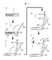
図2は、図1の機器1の略側面図であり、携帯可能状態から使用可能状態への形態の変化を説明するための図である。
【0051】
機器1は、携帯可能状態(図2(a)参照)では薄い箱型をしており、持ち運びに便利な形態となっている。使用する場合には、まず蓋部500を開き、蓋部500に備えられた反射型液晶表示装置100を観察可能とする(図2(b)参照)。 周囲が明るい環境下であれば、この状態で、画像は、十分に観察できるので本機器は使用可能となる。暗い環境下であれば、機器1に備えられた照明装置200を所定の位置に移動して、反射型液晶表示装置100を前方から照明することになる。
【0052】
本実施例では、照明装置200は、本体部300の両サイドに備えられた2本の棒状の可動支持部400を介して本体部300に備えつけられている。可動支持部400と本体部300、及び可動支持部400と照明装置200とはそれぞれ回転軸部401、及び回転軸部405において回転可能に接続されている。また、可動支持部400は中空構造をした2つの棒状部400aと400bとをスライド可能に接続して伸縮可能、つまり長さが変えられる構造としている(図2(c)〜(e)参照)。
【0053】
携帯可能状態、もしくは明るい環境下で照明装置200を必要としない場合、照明装置200は本体部300と一体化し、収納した状態となるため携帯性や操作性を阻害しない構成となっている(図2(a)、(b)参照)。
【0054】
照明装置200を使用する場合は、まず、回転軸部401を中心に可動支持部400を回転して、照明装置200を反射型液晶表示装置の前方に移動する(図2(c)参照)。さらに、可動支持部400を長く伸ばし、回転軸部405を中心に照明装置200を回転して、照明装置200の光出射部を反射型液晶表示装置に向けることで反射型液晶装置の表示面を照明することが可能となる(図2(d)、(e)参照)。
【0055】
つまり、照明装置200は、可動支持部400によって反射型液晶表示装置前方の所定位置に配置したり、本体部300と一体化した収納状態とすることを必要に応じて行うことができる構造となっている。
【0056】
照明装置200は、光源として小型、高発光効率、低発熱といった条件を満たすものを用い、光源からの出射光を効率よく反射型液晶表示装置100に照射する構成とする。
【0057】
光源としては、冷陰極管や熱陰極管等の蛍光灯、あるいはLED(Light Emitting Diodes)、EL(Electroluminescence)等の発光素子を用いることができる。
【0058】
図3は、照明装置200の一例の概略構成を示す一部斜視図である。また、図4は、図3の照明装置200の一部断面図である。本実施の形態例の照明装置200は、円筒状の冷陰極管からなる光源210と、光源210を包み込むように配置した開口部を有する反射板220と、光源210からの出射光を照射対象に導くためのガイド部240と、反射板220の開口部の前方に配置した拡散板230とで構成される。
【0059】
ここで、本実施の形態例では表示部の大きさが192mm×72mm(横方向長さ×縦方向長さ)の反射型液晶表示装置100を用いる。これに対応して光源210は反射型液晶表示装置表示部の横幅よりも発光部長さがやや長い、発光部長さ200mm、直径2.0mmの円筒状の冷陰極管を用いた。
【0060】
反射板220は、光源210からの出射光を効率良く照射対象方向へ反射するためのもので、円筒形、或いは楕円筒形等の一部に開口部を有する形状の反射板、或いは反射フィルムを使用することができる。具体的には、反射板220は、高分子フィルムの表面に銀や、アルミニウム等の金属薄膜層を蒸着法、或いはスパッタリング法により成膜し、高分子フィルムシートやアルミニウム板等の支持板にラミネートしたものを用いることができる。ここでは商品名:LU-02-AM50(三井化学製)の銀反射板を用いた。
【0061】
拡散板230は、光源光の角度分布や、光量分布を均一化する機能を有するものである。拡散板としてはポリエチレンテレフタレート等の高分子フィルムの表面に凹凸を形成したもの、或いはフィルム内部に気泡を混入して光拡散性を持たせたもの、或いはアクリル等の透明部材中に白色顔料を分散させた乳白色部材等を使用することができる。
【0062】
ガイド部240は、光源からの出射光を照射対象である反射型液晶表示装置100の表示面にできるだけ過不足なく照明するための補助部材であり、内面が鏡面反射面、或いは拡散反射面で構成される枠状の部材である。また、ガイド部240は、照明装置200からの出射光が直接観察者へ向かうことを防ぐための遮光部材としての機能も有する。
【0063】
光源210への電力供給は、本体部300に内蔵する電源から可動支持部400内を通した配線、及びインバーターを介して行なわれる。
【0064】
上記構成により、光源210から出射する光は直接、或いは反射板220で反射した後、拡散板230に入射し、角度分布や光量分布が均一化された後、カイド部240を介して照射対象である反射型液晶表示装置100に向かう。この際、照明装置200は、反射型液晶表示装置表示面100の横幅よりも長い面光源として作用し、少なくとも液晶表示装置表示面の左右方向に関しては入射光の角度分布が対称で、均一な照明が可能となる。
【0065】
なお、照明装置200は、照明装置200を支持する可動支持部400を回転軸部401を中心に回転させた際、その位置により自動で点灯、消灯するようにしても差し支えない。しかし、不要な点灯による電力消費を押さえるために、スイッチを設けて照明装置200の点灯消灯を任意に行えるようにするとよい。
【0066】
反射型液晶表示装置(以下、液晶表示装置と略す)100としては、TFT(Thin Film Transistor)等のスイッチング素子を用いたアクティブマトリクス駆動による液晶表示装置や、マルチプレックス駆動の液晶表示装置を用いることができる。
【0067】
また、表示モードとしてはTN(Twisted Nematic)型やSTN(Super Twisted Nematic)型、ECB(Electrically Controlled Birefringence)型、VA(Vertical Aligned)型、HAN(Hybrid Aligned Nematic)型 等の偏光状態を変調して表示を行うモードと、GH(Guest Host)型のように2色性色素により光の吸収制御を行う表示モード等を使用することができる。さらに、偏光状態を変調する表示モードとしては偏光板を2枚使用し、反射部を外付けするタイプと、反射部を内蔵して1枚の偏光板で表示を行う単偏光板タイプを用いることができる。
【0068】
ここでは初めに、偏光板を2枚使用するSTNモードを使ったモノクロ液晶表示装置の場合について説明するが、本発明はこれに限定されるものではない。
【0069】
なお、上述の構成により本発明の表示装置では照明装置からの照明光の主光束は液晶表示装置に対して、その表示面垂線方向から傾いた所定の方向、つまり斜め方向から入射するよう構成される。このため、本発明に係る液晶表示装置は照明装置から出射し、所定の斜め方向から表示面に入射する光に対し、高い反射率、及びより高いコントラスト比が得られる構成とすることが画質向上の面から必要である。
【0070】
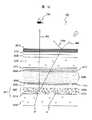
図5は、図1の液晶表示装置100の概略構成を示す一部断面図である。液晶表示装置100は、画像形成部101、及びその背面に配置した反射部190とから構成される。
【0071】
画像形成部101は、絶縁性の透明基板からなる第1の透明基板110、及び第2の透明基板120と、これら2枚の基板をビーズ等のスペーサを介して張り合わせ、枠状のシール材によりシールして形成した2枚の基板の間隙に封入、封止した液晶層130と、第1の透明基板110上に積層配置された位相差板160及び偏光板170と、第2の透明基板の背面に配置した偏光板180とから構成される。
【0072】
ここで、本実施の形態例の液晶表示装置100、及びそれを備えた機器1では、照明装置200を、液晶表示装置100の前方であって、表示面の直上部を除いた所定の位置に配置し、表示面垂線方向からずれた方向、つまり斜め方向から表示面を照明するように構成する。
【0073】
従って、本実施の形態例の液晶表示装置100の反射部190は、液晶表示装置100に斜めに入射する照明装置200からの照明光800を観察者700の方向へ反射する機能を有するものとすることが重要である。
【0074】
この際、照明装置200と液晶表示装置100とが十分に離れていれば、液晶表示装置100の表示面を均一に照明することは比較的容易である。
【0075】
しかし、本実施の形態例の液晶表示装置100、およびそれを備えた機器1では、照明装置200を本体部300に備えるため、照明装置200と液晶表示装置100との間に十分な距離を確保することは難しい。このため、照明装置200からの照明光の強さや、光入射角度が、液晶表示装置100の表示面の位置毎に異なり、表示面を均一に照明することは困難である。
【0076】
そこで、本実施の形態例の液晶表示装置100の反射部190は、照明装置200から出射し、所定の斜め方向から表示面に入射する光を観察者方向へ反射するような指向性を有し、この指向性を表示面の各位置における照明光の光入射角度や、強さに応じて最適化することで表示面内で均一な表示を得るようにしたものである。
【0077】
本実施の形態例では、照明装置200から液晶表示装置100の表示面に斜めに入射する照明光800を観察者700の方向へ反射する機能を、表示面に対して傾斜した非対称な3角溝(柱)状の複数の微細構造からなる鏡面反射面191(以下、微小傾斜反射面191と称す)と、光拡散層192とから構成する反射部190で実現した。
【0078】
微小傾斜反射面191の傾き角度α(以下、微小傾斜角度αと称す)は、照明光の主光束を観察者700の方向へ反射する角度に設定する。ここでは、観察者700が通常、液晶表示装置100の表示を表示面垂線方向、もしくはその近傍から観察することが多いことを鑑み、表示面に斜めに入射する照明光800を表示面垂線方向へ反射するように構成した。
【0079】
なお、上述の通り本実施の形態例では、照明装置200は、液晶表示装置100の表示面の横幅よりも長い面光源として作用し、液晶表示装置表示面の左右方向に関しては照明光の入射角度の分布はほぼ対称となるので、反射部190には表示面の左右方向に対して格別な指向性は付与しない。つまり、微小傾斜反射面191を成す微細な3角溝構造は、その長手方向を表示面左右方向と平行となるよう構成して、表示部上下方向に格別な指向性を付与するようにした。
【0080】
図6は、照明光の表示面への入射角度と、微小傾斜角度αの関係を説明するための図である。ここで、微少傾斜角度αは、表示面に対して傾斜した非対称な3角溝を成す微細な2つの反射面のうち、有効反射面となる微少傾斜反射面が表示面と平行な面と成す角度である。
【0081】
外界(空気)の屈折率をn1、鏡面反射面191を覆う光拡散層192の屈折率をn2とし、照明光の表示面への入射角度をθ1とすると、微小傾斜角度αは概ね
α=(sin-1(sinθ1・n1/n2))/2 ……… (数1)
とすればよい。
【0082】
図7は、図1の携帯情報機器の側面図である。図7に示す通り、液晶表示装置100の表示面の上部に入射する照明光800の主光束の入射角度は約35°なので、 表示面上部に対応する反射部190の鏡面反射面191の微小傾斜角度αは11°とし、表示面の下部に入射する照明光の主光束の入射角度は約63°なので表示面下部に対応する反射部190の鏡面反射面191の微小傾斜角度αは18°とした。また、表示面上部から下部へかけて反射部190の鏡面反射面191の微小傾斜角度αを11°から18°へ照明光が表示面垂線方向へ反射されるように連続的に増加させた。
【0083】
なお、角度β、すなわち微小傾斜反射面191のうち、無効反射面となる面が表示面と平行な面となす角度(図6参照)は、鏡面反射面191に至る照明光の入射角度よりも大きくなると鏡面反射面191に影が生じ、小さくなると観察者側へ反射されない光成分が増えて表示の明るさが減少する。
【0084】
このため、角度βは、鏡面反射面191に至る照明光の主光束の角度と実質的に同じとすることが望ましく、
β=sin-1(sinθ1・n1/n2) ……… (数2)
とした。
【0085】
また、微小傾斜反射面191を構成する微小三角溝のピッチPは30μmとした(図6参照)。
【0086】
微小傾斜反射面191は、以下の通り作成した。まず、機械加工により微少な傾斜部を構成する3角溝からなる微小傾斜反射面の金型を作成する。次に、この金型を用いて熱硬化性樹脂に微小傾斜反射面を転写し、その表面にアルミニウム或いは銀といった反射率の高い金属膜を蒸着して微小傾斜反射面を形成する。
【0087】
光拡散層192は、鏡面反射面191に照明装置の像が形成され、視認されることの防止、及び規則的なパターンである微小傾斜反射面191での干渉による色付き防止、及び反射光の拡散性(ゲイン)の調整手段として機能するものである。
【0088】
光拡散層192は、以下の通り作成した。まず、ビスフェノールA型エポキシ樹脂(EP827、エポキシ当量180)を重量比で50、メチルヘキサヒドロ無水フタル酸(NH8210、酸当量162)を重量比で50混合して透明媒体を得る。次に、この透明媒体に硬化剤として2−エチル−4メチルイミダゾールを少量加え、さらに、ポリメチルメタクリレート(PMMA)からなる平均粒径7μmの透明体を平均重量比で20混合し、これを微小傾斜反射面191に塗布し、さらに偏光板180を積層して約30μmの膜厚としたのち、加熱(約100℃で2時間)して硬化した。
【0089】
偏光板180と光拡散層192の屈折率差は小さいので、これにより偏光板180と反射部190との界面反射は減る。
【0090】
ここで、EP827及びNH8210からなる透明媒体194の屈折率は1.53であり、透明媒体中に分散したPMMAからなる透明粒子193の屈折率は1.49であるため、光拡散層192はこの屈折差により光散乱手段として機能する。
【0091】
従って、透明媒体194に分散する透明粒子193の混合比を変えることで光散乱性が変化し、反射光の拡散性を変えることができる。すなわち、透明媒体194に対する透明粒子193の混合比を大きくすれば拡散性が上がり、微小傾斜反射面191での正反射方向の光量は減り、透明粒子193の混合比を小さくすれば微小傾斜反射面191での正反射方向の光量は増える。
【0092】
ここで、本実施の形態例では、液晶表示装置100の表示面はその位置毎に照明装置200からの距離が異なる。つまり、照明装置200との距離は、表示面下部では長く、表示面上部では短いため、照明装置からの照明光の強さが表示面下部から表示面上部に向かって連続的に強くなる。
【0093】
そこで、本実施の形態例では、液晶表示装置100の表示面上部に相当する光拡散層192には透明粒子193を重量比で22混合し、表示面下部に向かって連続的にその混合比を減少させ、表示面下部に相当する拡散層192には透明粒子193を重量比で18混合した。
【0094】
上記構成の反射部190によれば、照明光の弱い表示面下部に比べて、照明光の強い表示面上部では光拡散層192の拡散性が連続的に高くなり微小傾斜反射面191での正反射成分も連続的に減るため観察者には均一な明るさの表示(反射光)が得られる。
【0095】
次に、液晶表示装置100の画像形成部101について説明する。
第1の透明基板110、及び第2の透明基板120は、ガラス、或いは高分子フィルム等の透明で平坦な光学的に等方な基板を用いることができる。ここでは両透明基板として厚さが0.7mmのガラス基板を使用し、それぞれの表面にITO(インジウム ティン オキサイド)から成るストライプ状の透明電極113、121をパターニングした。さらに、両透明基板の透明電極形成面側の表示領域に配向膜112、122としてポリイミド系配向膜LQ-1800(日立化成製)を厚みが約500Åとなるように塗布し、ラビング法により表面処理を行った。
【0096】
2枚の透明基板110、120は、ストライプ状にパターニングされた透明電極113、及び透明電極121が行列状となるように対向配置し、その交差部にマトリクス状の画素部を形成して単純マトリクス方式の液晶表示装置として機能するように構成した。
【0097】
透明電極113及び透明電極121は、本体部300、或いは蓋部500に備えるドライバ用ICに接続され、画像情報に応じた電圧を各画素部に選択的に印加できるよう構成した。
【0098】
貼り合わせた2枚の透明基板の間隙は、透明基板間に分散配置したジビニルベンゼンからなるビーズスペーサーにより形成した。この際、間隙は5.7μmとした。
【0099】
2枚の透明基板間には誘電異方性が正のネマチック液晶MJ63928(メルク社製)にカイラル剤S-811(メルク社製)を少量添加した液晶組成物を封入、封止して液晶層130を構成した。この場合の液晶層130のΔndは0.83μmであった。ここで、Δnは液晶の複屈折、dは液晶層の厚さである。
【0100】
液晶層130の液晶分子は、配向膜112、122に行う表面処理によって透明基板間で約240度ねじれるように構成した。また、この際のプレチルト角は約4度とした。
【0101】
偏光板170及び180としては、延伸させたポリビニルアルコールにヨウ素を吸収させて偏光機能を付与した膜の両面にトリアセチルセルロースの保護層を施したものを用いた。それぞれ位相差板160及び第2の透明基板120にアクリル系の接着剤によって光学的に結合するよう、すなわち各層での屈折率差が小さくなるように接着した。
【0102】
位相差板160としては、例えばポリカーボネート、ポリサルホン、ポリビニルアルコール等の一軸延伸した高分子フィルムを用いることができる。ここでは波長550nmにおけるΔndが0.63μmのポリカーボネートからなる位相差板を用いた。ここでΔnは位相差板の複屈折、dは位相差板の厚さである。
【0103】
位相差板160の遅相軸、偏光板170及び偏光板180の直線偏光の吸収軸、及び液晶分子の配向軸は、照明装置200から出射し、液晶表示装置100に斜めに入射する照明光を効率よく利用できる条件とすることが必要である。
【0104】
本実施の形態例では、以下に示す条件で液晶表示装置100を構成した。
図8は、図1の液晶表示装置100の構成条件を示す図であり、観察者から見た際の液晶表示装置各部の軸の方向を示す図である。
【0105】
また、図9は、本明細書における方位角φと、仰角ζの定義の説明図である。図9に示す通り、本明細書では方位角φを液晶表示装置表示面の左右方向の軸上であって、時計における3時の位置を0°とし、反時計回りに定義する。また、仰角ζは液晶表示装置表示面の垂線に対する傾き角度として定義する。
【0106】
図8に示す通り、液晶表示装置100は、偏光板170の吸収軸の方位角は255°、位相差板160の遅相軸の方位角は185°、透明基板110側の液晶配向軸の方位角は105°、透明基板120側の液晶配向軸の方位角は165°、偏光板180の吸収軸の方位角は120°とした。
【0107】
本構成の液晶表示装置100に入射した照明光のうち偏光板170を透過した直線偏光は、位相差板160、液晶層130を通過して偏光板180に入射する。この際、液晶層130を透過する光の偏光状態は液晶層130に印加する電圧によって変化させることができる。
【0108】
このため、画像情報に対応した電圧を透明電極113、及び透明電極121に印加し、液晶層130に電圧を印加することで、液晶層130を通過する光の偏光状態を変え、偏光板180を透過する光量を制御して光学画像を形成することができる。
【0109】
また、液晶表示装置100に入射し、偏光板180を透過した光は、反射部190で反射して、再び偏光板180、液晶層130、位相差板160を通過して偏光板170に入射する。このときも液晶層130に印加される電圧により偏光板170を透過する光量は制御され光学画像が形成される。
【0110】
上記構成により、本液晶表示装置100はノーマリーオープン特性が得られる。ノーマリーオープン特性とは液晶層に印加される電圧が小さい時の透過率が高く、電圧を高くすると透過率が低下する特性のことである。
【0111】
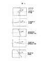
図10は、上記構成による液晶表示装置100の画像形成部101の光入射角度と、透過率の関係を明表示と暗表示の場合について示した図である。光入射角度は、正の角度が方位角90°における仰角を表し、負の角度が方位角270°における仰角を表す。
【0112】
本実施の形態例では、照明装置200からの照明光は液晶表示装置100の上方、つまり方位角90°方向から入射することになるので、図中、正の光入射角度が照明装置200からの照明光の光入射角度に相当する。
【0113】
図示の通り、本液晶表示装置100の画像形成部101は斜め方向から光が入射しても明表示の透過率は大きく低下せず、明るい表示が得られる。
【0114】
また、暗表示の場合は液晶表示装置100の画像形成部101に垂直に入射する光に対しては低い透過率となり十分な暗表示が得られ、斜め方向から入射する光に対しては高い透過率が得られる。
【0115】
この特性は、本発明の機器1のように、照明装置200からの照明光が液晶表示装置100に斜めに入射する際に懸念される「暗表示部の影」発生の抑制に有効である。
【0116】
ここで、「暗表示部の影」について、図面をもとに説明する。
図11は、「暗表示部の影」の説明図である。暗表示画素部と明表示画素部とが隣接する場合を考えると、液晶表示装置100には照明光800が斜めに入射するため、暗表示画素部の影が、隣接する明表示画素部の真下の反射部190に生じる。この影は、透明基板120や偏光板180の厚み、すなわち液晶層130と反射部190との距離が長いために生じる。反射部190はこれに斜めに入射する照明光を観察者700の方向へ反射するため、明表示画素部の表示には隣接する暗表示画素部の影が写り、いわゆる「暗表示部の影」が生じて画質が著しく低下する。
【0117】
本実施の形態例の液晶表示装置では、図10に示す通り、照明装置200から出射し、液晶表示装置100に斜めに入射する光は暗表示画素部であっても高い透過率となり、影ができにくいので「暗表示部の影」の発生が抑制されるという効果がある。
【0118】
上記の通り、本実施の形態例では、補助照明装置として液晶表示装置100の前方であり、かつその表示面からは離れた位置に光出射部を備えた照明装置200を移動可能に備え、機器使用者が表示部を観察する際に邪魔にならない位置から液晶表示装置100の表示面を照明するように構成した。つまり、照明装置200は、液晶表示装置100の表示面直上部を除く位置で、表示面垂線方向からずれた斜めの方向から表示面を照明するように構成した。
【0119】
このため、導光体式前方照明装置のように導光体等の光損失の原因となるような複雑な光学系を必要としないため効率の良い照明ができる。また、液晶表示装置の表示面上に導光体等の付加部材を配置しないため、付加部材による表示の劣化や、タッチパネル使用時の視差といった導光体式前方照明装置特有の課題が回避できる。
【0120】
なお、投写式前方照明装置では照明光の強さや照明光の入射角度が表示面の位置により異なり、表示面内で均一な明るさの表示を得ることが困難である。
【0121】
しかし、本実施の形態例の液晶表示装置100の反射部190は、その反射角度や指向性を表示面の各位置における照明光の光入射角度や、強さに応じて最適化して、所定の位置に配置した照明装置200からの照明光を観察者側へ均一に反射するように構成したので、反射部190を従来の拡散反射板とする場合に比べて約2倍明るく、面内の均一性が高い表示が得られた。
【0122】
さらに、図7に例示するとおり、液晶表示装置100の表面等の界面での正反射光1000の方向と、画像光900の方向は異なるため、照明装置200の像が観察されて画質が劣化することがないという効果もある。
【0123】
さらに、液晶表示装置100は、所定の位置に配置した照明装置から出射し、斜めに入射する照明光に対し、高い反射率となる表示モードを選択したので、より高品位な画質が得られるという効果もある。
【0124】
さらに、本実施の形態例の通り、照明装置200を液晶表示装置100の上部に配置するように構成することで、以下の効果も得られる。
【0125】
液晶表示装置100は、周囲が明るい環境下では照明装置200を使用することなく外光のみでの使用が可能である。この際、外光の大部分は液晶表示装置100の上方から入射する。特に本実施の形態例のように、キーボードを有する機器では液晶表示装置100の下方から外光が入射することは少なく、外光の大部分は液晶表示装置100の上方から入射する。
【0126】
従って、照明装置使用時の照明装置200の配置位置を液晶表示装置100の上部とし、上方から入射する光に対応した指向性反射機能を有する反射部190を構成することで照明装置不使用時に液晶表示装置100の上方から入射する外光が効率よく観察者側へ反射できるので、より明るい画像が得られるという効果がある。
【0127】
また、暗闇の中で作業する場合は、図7に例示するとおり、上部に配置した照明装置200からの照明光のうち液晶表示装置100の表面等で正反射した光がキーボードや手元を照明することになり、作業性が上がるといった効果もある。
【0128】
さらに、このような照明装置200と液晶表示装置100とを備える機器1は、明るい環境下では機器1に備える照明装置200を使用せずに外光のみで表示をみることができ、周囲の照明が暗い場合には機器1に備えた照明装置200を使用することで良好な視認性を確保できる。
【0129】
このため、周囲の環境によらずいつでも良好な視認性を確保できるとともに、必要な場合にのみ照明装置200を用いることで機器全体の消費電力が低減できるという効果がある。
【0130】
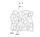
なお、上記実施の形態例では、モノクロ表示の液晶表示装置の場合について説明したが、透明基板110、或いは透明基板120のいずれかに赤色、緑色、青色の3原色に相当するマイクロカラーフィルタを形成してカラー表示を行うようにしてもよい。
【0131】
例えば、透明基板110上に上下方向に伸びるストライプ状のカラーフィルタを形成し、オーバーコート層を介してカラーフィルタに対応する位置にITOからなる透明電極を形成する。この際、カラーフィルタの画素間に相当する位置にはブラックマトリクスを形成するようにしてもよい。
【0132】
ここで、上記実施の形態例のように、照明装置200が液晶表示装置100の上方に備えられる場合は、照明装置200からの照明光の主光束は方位角90°から所定の仰角をもって入射するため、図12に示す通り、反射部の微小傾斜反射面を成す微細な3角溝構造の長手方向(以下、微小傾斜反射面の長手方向)は表示面左右方向に平行となるように構成される。これに対して、ストライプ状のカラーフィルタは、その長手方向を微小傾斜反射面の長手方向と直交する方向、すなわち表示面の上下方向に平行とすることが重要である。
【0133】
これは、もしストライプ状のカラーフィルタの長手方向が左右方向、或いはカラーフィルタがデルタ配置であれば、上下方向で隣接した画素間でカラーフィルタの色が異なるため方位角90°の方向から所定の仰角をもって斜めに入射し、反射する光の一部は往路復路の行程で異なる色のカラーフィルターを通過するため吸収されて有効に光が利用できなくなるからである。
【0134】
つまり、カラーフィルタは照明装置200からの照明光の主光束の方向に平行となる方向に連続的に形成することが効率の面から重要である。
【0135】
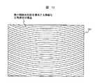
ところで、上記実施の形態例では、微小傾斜反射面の長手方向を表示面左右方向と平行となるよう構成した。これは、観察者700が通常、液晶表示装置100の表示を表示面垂線方向、もしくはその近傍から観察することが多いことを鑑み、表示面に斜めに入射する照明光を表示面垂線方向へ反射するよう構成したためである。
【0136】
しかし、液晶表示装置100のサイズが大きくなると、照明光を表示面垂線方向へ反射する構成では表示面の周辺部が観察者700に暗く見えるようになる。この場合は、図13に例示するように、微小傾斜反射面を構成する微細な三角溝構造を直線的ではなく、曲線的にし、所定の方向から入射する照明光を観察者700の方向へ反射、集光するような指向性を反射部に付与することで、周辺部も明るく均一な表示を実現するようにしても良い。
【0137】
また、本実施の形態例では、微小傾斜反射面の上に光拡散層を形成することで照明装置の像が視認されることの防止、干渉による色付き防止、及び反射光の拡散性の調整を行ったが、本発明は、これに限定されるものではなく微小傾斜反射面の上に微少な凹凸部からなる拡散部を形成することで光拡散性を付与するようにしても良いし、或いは前方散乱性のフィルムを第1の透明基板の上層に配置するようにしても良い。
【0138】
次に、本発明の他の実施の形態例に係わる液晶表示装置について説明する。
【0139】
図14は、本発明の他の実施の形態例に係わる液晶表示装置の一部概略断面図である。本実施の形態例は、反射部190にホログラムを使用したこと以外は上記実施の形態例と同様の構成である。よって、上記実施の形態例と共通な部分については詳しい説明は省略し、変更部分について詳述する。
【0140】
上述の通り、本発明の要点の一つは、照明装置から斜めに入射する照明光を観察者方向に均一に反射する反射部190を有することにある。本実施の形態例はこれをホログラムで実現するものである。即ち、反射部190として斜め方向から入射する照明光を観察者700の方向へ回折反射するホログラム反射板を用いる。
【0141】
反射部190は、ホログラム1110と反射板1120とから構成される。
【0142】
ホログラム1110は、照明装置から出射し、表示面の位置毎に異なる角度で入射する照明光800に対し、観察者700が表示面全体から均一な反射光800を得られるようにするために、各位置で異なる角度へ回折反射が起こるように作成したホログラムを用いる。
【0143】
ホログラム1110としては高い回折効率が得られるという点では体積位相型のホログラムが望ましい。また、ホログラムの作成は2光束干渉によって記録する公知の技術を用いればよく、例えば特開平9−138396号公報、特開平9−152586号公報等に記載の方法を用いることができる。また、所望のホログラムパターンを計算機によって算出し、電子ビーム等によって描画,作製するCGH(Computer Generated Hologram)を用いてもよい。
【0144】
ホログラム材料としては、アクリル系のフォトポリマーを用いることが耐久性等の面から望ましい。
【0145】
フルカラー表示に対応する場合は、ホログラムの中心回折波長を3原色に対応させればよく、例えば光源として赤色用にはHe−Neレーザー(633nm)、緑色用にはAr+Dyeレーザー(570nm)、青色用にはArレーザー(458nm)を用いて露光,作製したホログラムを用いればよい。この際、各波長で個別に露光した複数のホログラムを積層して用いてもよいが、1枚に複数の波長で多重露光したものを用いてもよい。
【0146】
このように作製したホログラムは、設計角度で入射する光に対しては回折反射を起こすが、設計角度と異なる角度で入射した光に対しては回折反射を起さず略透過する。このため、ホログラム1110の背面には反射板1120を配置して、ホログラム1110を透過する光も利用するようにすると良い。
【0147】
反射板1120としては、ポリエステルフィルムにアルミニウム或いは銀を蒸着し、表面を多少荒らすことで拡散性を付与した反射板を用いるようにするとよい。
【0148】
本実施の形態例においても、上記実施の形態例と同様、液晶表示装置100の反射部190は、その反射角度と指向性を表示面の各位置における照明光の光入射角度や、強さに応じて最適化し、所定の位置に配置した照明装置から出射し、表示面に斜めに入射する照明光800を観察者側へ均一に反射するように構成されるので、明るく面内の均一性が高い表示が得られるという効果がある。
【0149】
この際、液晶表示装置100の表面での正反射光1000の方向と、画像光900の方向は異なるため、照明装置の像が観察されて画質が劣化することがないという効果もある。
【0150】
図15は、本発明の更に他の実施の形態例に係わる液晶表示装置の一部概略断面図である。本実施の形態例は、液晶表示装置100の構成以外は上記実施の形態例と同様な構成としたため、上記実施の形態例と同様な部分については詳しい説明は省略し、液晶表示装置100について詳述することとする。
【0151】
本実施の形態例の液晶表示装置100は、反射部を内蔵した単偏光板タイプのSTN型液晶表示装置である。
【0152】
本液晶表示装置100は、透明基板2040、及び反射部2211を備える反射基板2200と、これら2枚の基板をビーズ等のスペーサを介して張り合わせ、枠状のシール材によりシールして形成した2枚の基板の間隙に封入、封止した液晶層2080と、透明基板2040上に積層配置された2枚の位相差板2030、位相差板2020、及び偏光板2010とから構成される。
【0153】
ここで、上述の通り、本実施の形態例の液晶表示装置100及びそれを備えた機器1では、照明装置200は液晶表示装置表示部の直上部とは異なる所定の位置に配置され、その照明光800は液晶表示装置に斜めに入射するよう構成される。
【0154】
従って、液晶表示装置100の反射部2211は、液晶表示装置100に斜めに入射する照明光800を観察者700の方向へ反射する指向性反射機能を有するものとする。さらに、反射部2211での反射の指向性を表示面の各位置での照明光800の光入射角度や、強さに応じて最適化して表示面内で均一な明るさが得られるように構成することが重要である。
【0155】
本実施の形態例では、照明装置から液晶表示装置100の表示面に斜めに入射する照明光800を観察者700の方向へ反射する機能を、反射基板2200に形成した表示面に対して傾斜した複数の非対称な3角溝状の微細構造からなる鏡面反射面2210(以下、微小傾斜反射面2210と称す)と、光拡散層2221とから構成される反射部2211で実現した。
【0156】
微小傾斜反射面2210の構成は、図5、及び図6を用いて説明した上記実施の形態例と基本的に同様の構成とすればよい。すなわち、微小傾斜角度αは前記実施の形態例と同様に照明光800の主光束を観察者700の方向へ反射する角度に設定する。ここでは観察者700が通常、液晶表示装置100の表示を表示面垂線方向、もしくはその近傍から観察することが多いことを鑑み、表示面に斜めに入射する照明光800を表示面垂線方向へ反射するよう構成した。
【0157】
また、上述の通り、本実施の形態例では、照明装置200は、液晶表示装置100の表示面横幅よりも長い面光源として作用し、液晶表示装置表示面の左右方向に関しては照明光の入射角度の分布はほぼ対称となるので、反射部2211では表示面の左右方向には格別な指向性は付与せず、微小傾斜反射面2210を成す微細な3角溝状の構造はその長手方向を表示面左右方向と平行となるよう構成することで、表示面の上下方向には格別な指向性を付与するようにした。
【0158】
微小傾斜角度αは、概ね式(数1)から算出される値とすれば良く、表示面のどの位置であっても照明光800が表示面垂線方向へ反射されるように表示面上部から下部にかけて微小傾斜角度の値を連続的に変化させた。また、微小傾斜反射面2210の角度βも式(数2)で算出される値とし、微小傾斜反射面2210を構成する微小な三角溝のピッチPは30μmとした。
【0159】
微小傾斜反射面2210は、反射基板2200上に以下の通り作成する。
まず、機械加工により微少な傾斜部を構成する3角溝からなる微小傾斜反射面の金型を作成する。次に、ガラス、或いは高分子フィルムといった平坦な絶縁性基板からなる反射基板2200上に熱硬化性樹脂を成膜し、これに金型を用いて微小傾斜反射面を転写し、硬化する。次に、微小傾斜反射面が転写された熱硬化性樹脂の表面にアルミニウム 、或いは銀といった反射率の高い金属膜を蒸着して微小傾斜反射面を形成する。
【0160】
本実施の形態例では、反射基板2200として厚さ0.7mmのガラス基板を用い、微小傾斜反射面形状を転写して硬化した熱硬化性樹脂の表面に銀を蒸着して微小傾斜反射面2210を得た。
【0161】
微小傾斜反射面2210の上には、さらに光拡散層2210が形成される。光拡散層2210は、微小傾斜反射面2210に照明装置の像が形成され、視認されることの防止、及び微小傾斜反射面2210での干渉による色付き防止、及び反射光の拡散性の調整手段として機能するものである。
【0162】
光拡散層2210も、図5を用いて説明した上記実施の形態例と同様に形成すれば良い。この際、以下の理由から液晶表示装置100の表示部上部に相当する光拡散層2210には透明媒体2230に混合する透明粒子2220をやや多めにし、表示部下部に向かって連続的にその混合比を減少させることで表示部下部から上部にかけて光拡散性が連続的に高くなるようにすると良い。
【0163】
つまり、本液晶表示装置100を備えた機器では照明装置が液晶表示装置100の上部に配置されるので、照明光の強さは液晶表示装置100の表示面上部の方が下部に比べて強い。
【0164】
このため、光拡散層2221の光拡散性を表示面下部から表示面上部に向かって連続的に高くすれば微小傾斜反射面2210での正反射成分は表示面下部から表示面上部にむかって連続的に減り、観察者800には均一な明るさの反射光が得られる。
【0165】
光拡散層2221は、以下の通り作成した。硬化剤を少量加えた透明媒体に、ポリスチレンからなる平均粒径4μmの透明粒子2220を平均重量比で10混合し、これを微小傾斜反射面2210に厚さ約9μmの膜厚となるように塗布し、硬化した。
【0166】
この際、透明媒体2230の屈折率は1.53であり、透明粒子2220の屈折率は1.59であるため、光拡散層2221はこの屈折差により光散乱手段として機能する。
【0167】
本実施の形態例では、表示面上部に相当する光拡散層2221には透明粒子2220を重量比で12混合し、表示部下部に向かって連続的にその混合比を減少させ、表示部下部に相当する光拡散層2221には透明粒子2220を重量比で8混合した。
【0168】
反射部2211の光拡散層2221の上には絶縁層2300を形成する。この際、STN表示モードは液晶層の厚さの変動が表示のむらになり易いため、絶縁層2300は、反射部2211の凹凸を平坦化する機能を有することが必要である。
【0169】
このため、絶縁層2300としては、スピンコート法等により成膜が可能で凹凸部の平坦化が容易なアクリル系樹脂、カルド系樹脂、ベンゾシクロブテン樹脂、ポリイミド系樹脂等の有機材料を用いることが望ましい。より高い平坦性が必要な場合は有機材料膜の上にさらに酸化シリコンや、窒化シリコン等の無機絶縁膜を形成し、さらにこの表面をCMP(化学機械研磨)等の表面研磨により平坦化するようにしてもよい。
【0170】
平坦化された絶縁層2300の上にはITOからなるストライプ状の透明電極2100をパターニングする。さらに、その上には表示面に相当する部分へ全面的にポリイミド系の配向膜2090を塗布して、ラビング法により表面処理を行う。
【0171】
一方、透明基板2040としてはガラス、或いは高分子フィルム等の光学的に等方で平坦な透明基板を用いることができる。
【0172】
ここでは、透明基板2040として厚さが0.7mmのガラス基板を使用し、その表面にマイクロカラーフィルタ2050を形成した。カラーフィルタ2050の上層には図示しないオーバーコート層を介してITOからなるストライプ状の透明電極2070を形成し、さらに表示面に相当する部分には全面的にポリイミド系の配向膜2060を塗布して、ラビング法により表面処理を行った。
【0173】
カラーフィルタ2070は、それぞれ赤色、緑色、青色の3原色に対応した透過スペクトルを有する3種類のストライプ状のカラーフィルターを交互に繰り返し配置したもので、ストライプの方向は以下の理由から表示面に対して上下方向とした。
【0174】
本実施の形態例のように、照明装置200液晶表示装置100の上方に備えられる場合には、照明装置200からの照明光の主光束は方位角90°から所定の仰角をもって斜めに入射するので、もし、上下方向に隣接した画素のカラーフィルタの色が異なれば液晶表示装置100に入射し、反射する光の一部が往路復路の行程で異なる色のカラーフィルターを通過することになる。この場合、異なる色のカラーフィルタを通過する光はほとんど吸収されて有効に利用できないので暗くなってしまう。
【0175】
従って、カラーフィルタは、照明装置200からの照明光の主光束の方位角と平行となる方向に連続的に形成するようにし、往路復路の行程で同じ色のカラーフィルターを通過するようにしてカラーフィルタでの光の吸収を少なくなるようにするようにした。
【0176】
なお、カラーフィルタの画素間に相当する位置にはブラックマトリクスを形成して画素間からの漏れ光を抑えることで、より高いコントラスト比を実現するようにしてもよい。
【0177】
また、照明装置200の光源の発光スペクトルのピーク波長をカラーフィルタの透過スペクトルと一致するようにし、カラーフィルタでの光の吸収を減らすようにするとよい。
【0178】
透明基板2040と反射基板2200は、ストライプ状にパターニングされた透明電極2070、及び透明電極2100が行列状となるように対向配置し、その交差部にマトリクス状の画素部を形成して単純マトリクス方式の液晶表示装置として機能するように構成した。
【0179】
透明電極2070及び透明電極2100は、本体部300、或いは蓋部500に備えるドライバ用ICに接続され、画像情報に応じた電圧を各画素部に選択的に印加できるよう構成した。
【0180】
貼り合わせた2枚の透明基板には透明基板間に分散配置したビーズスペーサーにより間隙が形成される。2枚の透明基板の間隙には誘電異方性が正のネマチック液晶にカイラル剤を少量添加した液晶組成物を封入、封止して液晶層2080を構成した。この場合の液晶層2080のΔndは0.81μmであった。
【0181】
液晶層2080の液晶分子は、配向膜2060、2090に行った表面処理によって透明基板間で約240度ねじれるように構成した。
【0182】
偏光板2010としては、延伸させたポリビニルアルコールにヨウ素を吸収させて偏光機能を付与した膜の両面にトリアセチルセルロースの保護層を施したものを用いた。
【0183】
位相差板2020と位相差板2030としては、例えばポリカーボネート、ポリサルホン、ポリビニルアルコール等の一軸延伸した高分子フィルムを用いることができる。ここでは、位相差板2020としてΔndが0.43μmのポリカーボネートからなる位相差板を用い、位相差板2030としてΔndが0.19μmのポリカーボネートからなる位相差板を用いた。
【0184】
偏光板2010、位相差板2020、位相差板2030及び透明基板2040は、それぞれアクリル系の接着剤により光学的に結合するように接着した。
【0185】
図16は、図15の液晶表示装置100の構成条件を説明するための図であり、観察者の方向から見た際の液晶表示装置各部の軸の方向を示す図である。
【0186】
図16に示す通り、本実施の形態例の液晶表示装置100は、偏光板2010の吸収軸の方位角を40°、位相差板2020の遅相軸の方位角を110°、位相差板2030の遅相軸の方位角を80°、透明基板2040側の液晶配向軸の方位角を330°、反射基板2200側の液晶配向軸の方位角を30°とした。
【0187】
上記構成により、本液晶表示装置100はノーマリークローズ特性が得られる。ノーマリークローズ特性とは液晶層に印加される電圧が小さい時に暗表示となり、電圧を高くすると明表示となる特性のことで、斜めから入射する光に対してのコントラスト比の低下がノーマリーオープンの場合よりも少ない。
【0188】
上記構成により、本実施の形態例においても、液晶表示装置100の反射部2211はその反射角度や、指向性を表示面の各位置における照明光の光入射角度や、強さに応じて最適化して、所定位置に配置した照明装置からの照明光を観察者側へ均一に反射するように構成したので、明るく面内の均一性が高い表示が得られるという効果がある。
【0189】
この際、液晶表示装置100の表面等の界面での正反射光の方向と、画像光の方向が異なるため、照明装置200の像が観察されて画質が劣化することがないという効果もある。
【0190】
また、カラーフィルタを照明装置200からの照明光の主光束の方向に平行となる方向に連続的に形成したので、液晶表示装置100に入射し、反射する光の一部が往路復路の行程で異なる色のカラーフィルターを通過し、吸収されることが抑えられるのでより明るい画像が得られ、色純度の低下が小さいという効果がある。
【0191】
さらに、このような照明装置200と液晶表示装置100とを備える機器1は明るい環境下では機器1に備える照明装置200を使用せずに外光のみで表示をみることができ、周囲の照明が暗い場合には機器1に備えた照明装置200を使用することで良好な視認性を確保できる。このため、周囲の環境によらずいつでも良好な視認性を確保できるとともに、必要な場合にのみ照明装置200を用いることで機器全体の消費電力が低減できるという効果がある。
【0192】
また、本実施の形態例特有の効果として、以下の効果が得られる。
本発明の液晶表示装置及びそれを備えた機器では照明装置からの照明光は液晶表示装置に斜めに入射するので、液晶表示装置に入射し、出射する光は往路復路の行程で異なる位置を通過することになる。この位置のずれは、液晶表示装置の液晶層と反射部との距離が長いと大きくなる。
【0193】
このため、反射部が背面側の基板のさらに背面に外付けされている場合は背面側の基板等の厚みの分だけ光の往路復路での位置のずれが大きくなり、照明光が往路復路の行程に於いて異なる画素を通過して明るさや色純度が低下したり、「暗表示部の影」といった問題を生じる。
【0194】
しかし、本実施の形態例では、反射部を背面側の基板と液晶層との間に内蔵したため、液晶層と反射部の距離が極めて短くなり光の往路復路での位置のずれが小さくなって照明光が斜め入射するために生じる画質の劣化が抑えられて、明るく、色純度の高い高品位な表示が得られるという効果がある。
【0195】
図17は、本発明の更に他の実施の形態例に係わる液晶表示装置の一部概略断面図である。本実施の形態例は、液晶表示装置100以外は上記実施の形態例と同様な構成としたため、上記実施の形態例と同様な部分については詳しい説明は省略し、液晶表示装置100について詳述することとする。
【0196】
本実施の形態例の液晶表示装置100は、反射部を背面側の基板と液晶層との間に内蔵した、単偏光板タイプのTNモードの反射型液晶表示装置である。
【0197】
本液晶表示装置100は、透明基板3030、及び反射部を備える反射基板3100と、これら2枚の基板をビーズ等のスペーサを介して張り合わせ、枠状のシール材によりシールして形成した2枚の基板の間隙に封入、封止した液晶層3130と、透明基板3030に積層配置した位相差板3020、及び偏光板3010とから構成される。
【0198】
反射基板3100としては、ガラスや高分子フィルム等の平坦な絶縁基板をもちいればよく、ここでは厚さ0.7mmのガラス基板を用いた。反射基板3100には、走査電極と信号電極、及びこれらの交差部に備えられた例えばTFT(Thin Film Transistor)等からなるスイッチング素子3110と、これらの上部に形成した絶縁層3090と、絶縁層の上に形成され、絶縁層3090に開けられたスルーホール3120を介してスイッチング素子と電気的に接続されたマトリクス状に細分化された画素電極3070とが備えられる。
【0199】
画素電極3070は、アルミニウム、銀といった反射率の高い金属からなり、絶縁層3090上に形成された微細な凹部または凸部形状により、指向性のある反射部として機能するものである。画素電極3070の上層にはポリイミド系高分子からなる配向膜3060が全面的に形成され、その表面はラビング法等により表面処理がなされる。
【0200】
透明基板3030としては、ガラス、高分子フィルムなどの光学的に等方で平坦な透明絶縁基板を用いることができ、ここでは厚さ0.7mmのガラス基板を用いた。
【0201】
透明基板3030には、反射基板3100の画素電極3070に対応する位置にカラーフィルタ3040を形成する。カラーフィルタ3040はそれぞれ赤色、緑色、青色の3原色に対応した透過スペクトルを有する3種類のストライプ状のカラーフィルターを交互に繰り返し配置したもので、ストライプの方向は以下の理由から表示面に対して上下方向とした。
【0202】
本実施の形態例のように、照明装置200が液晶表示装置100の上方に備えられる場合には、照明装置200からの照明光800の主光束は方位角90°から斜めに入射するので、上下方向に隣接した画素のカラーフィルタの色が異なれば液晶表示装置100に入射し、反射する光の一部が往路復路の行程で異なる色のカラーフィルターを通過することになる。この場合、異なる色のカラーフィルタを通過する光はほとんど吸収されて有効に利用できない。
【0203】
従って、カラーフィルタは、照明装置200からの照明光800の主光束の方位角と平行となる方向に連続的に形成し、往路復路の行程で同じ色のカラーフィルターを通過するようにしてカラーフィルタでの光の吸収損失を少なくなるようにした。
【0204】
なお、カラーフィルタの画素間に相当する位置にはブラックマトリクスを形成して画素間からの漏れ光を抑えることで、より高いコントラスト比を実現するようにしてもよい。
【0205】
さらに、照明装置200の光源の発光スペクトルのピーク波長をカラーフィルタの透過スペクトルと一致するようにし、カラーフィルタでの光の吸収を減らすようにすると良い。
【0206】
カラーフィルタ3040の上層には、図示しないオーバーコート層を介してITOからなる透明電極3050を全面的に形成し、さらに透明電極3050の上層にポリイミド系高分子からなる配向膜3210を全面的に形成して、その表面をラビング法等により表面処理を行う。
【0207】
透明基板3030と反射基板3100は、透明電極3050形成面及び反射電極3070形成面が対向するよう貼り合せる。この際、両基板間にビーズスペーサを分散配置し、両基板の表示面相当部分の周囲を枠状のシール材によりシールすることで一定の間隙を有する空間が形成される。
【0208】
両基板の間隙には、誘電異方性が正のネマチック液晶にカイラル剤を少量(0.1〜0.2%)添加した液晶組成物を封入、封止して液晶層3130を構成した。液晶層3130のΔndは0.365μmとした。
【0209】
液晶層3130の液晶分子長軸の方向は、透明基板3030、及び反射基板3100上に形成された配向膜3210、及び配向膜3060に行なわれた表面処理(配向処理)によって配向方向が規定され、2枚の基板間で連続的に所定の角度だけねじれた状態となる。
【0210】
透明基板3030には、位相差板3020と偏光板3010とが積層される。
【0211】
位相差板3020としては、例えばポリカーボネート、ポリサルホン、ポリビニルアルコール等の一軸延伸した高分子フィルムを用いることができる。ここでは位相差板3020としてΔndが0.18μmのポリカーボネートからなる位相差板を用いた。
【0212】
偏光板3010としては、延伸させたポリビニルアルコールにヨウ素を吸収させて偏光機能を付与した膜の両面にトリアセチルセルロースの保護層を施したものを用いた。
【0213】
偏光板3010、位相差板3020、及び透明基板3030は、それぞれアクリル系の接着剤により光学的に結合するように接着した。
【0214】
上記構成により、液晶表示装置100に入射した光のうち偏光板3010を透過した直線偏光は、位相差板3020、液晶層3130を通過し、画素電極3070で反射して、再び液晶層3130、位相差板3020を通過して偏光板3010に入射する。この際、液晶層3130を透過する光の偏光状態は液晶層3130に印加する電圧によって変化する。
【0215】
ここで、スイッチング素子3110は画素電極3070にスルーホール3120を介して接続されており、画素電極3070に印加する電圧をスイッチングすることで、透明電極3050と画素電極3070とに挟まれた液晶層3130に印加する電圧を画素毎に制御することができる。
【0216】
従って、画像情報に対応した電圧を透明電極3050と画素電極3070とに印加し、液晶層3130に所定の電圧を印加することで、液晶層3130を通過する光の偏光状態を制御し、偏光板3010を透過する光量を制御して光学画像を形成することができる。
【0217】
ところで、本実施の形態例の液晶表示装置100及びこれを備えた機器1では照明装置200からの照明光800は液晶表示装置100に斜めに入射するよう構成される。従って、液晶表示装置100の反射部は、液晶表示装置100に斜めに入射する照明光800を観察者700の方向へ反射する機能(指向性反射機能)を有するものとする。この際、反射部での反射の指向性を表示面の各位置での照明光の光入射角度や、強さに応じて最適化して表示面内で均一な明るさが得られるように構成することが重要である。
【0218】
本実施の形態例では、反射率の高い金属膜で構成される画素電極3070に非対称な傾斜角度分布を有する複数の凸部を形成することで指向性反射機能を有する反射部を実現した。
【0219】
画素電極3070の複数の微小な凸部は、以下の通り作成する。
【0220】
まず、反射基板3100上にスイッチング素子3110、走査電極、信号電極等を形成し、その上に絶縁層3090を形成する。絶縁層としてはアクリル系樹脂、カルド系樹脂、ベンゾシクロブテン樹脂、ポリイミド系樹脂等の有機材料や、酸化シリコン、窒化シリコン等の無機材料を用いることができる。
【0221】
この際、スピンコート法等による成膜技術でスイッチング素子等の凹凸形状を容易に平坦化できることから絶縁層としては有機材料を用いることが望ましい。より高い平坦性が必要な場合は、有機材料膜の上にさらに酸化シリコン等の無機絶縁層を形成し、さらにこの表面をCMP(化学機械研磨)等の表面研磨により平坦化してもよい。
【0222】
本実施の形態例では、絶縁層としてアクリル系樹脂を塗布し、その膜厚を2μmとした。また、絶縁層3090には20μm□のコンタクトホール3120を形成した。
【0223】
図18は、微細な凸部を備えた反射機能を有する画素電極の製造工程を説明するための一部断面図である。
【0224】
図18(a)に示す通り、絶縁層を形成し、平坦化した反射基板3200の上に凸部形成材料となる有機系のメルトフローフォトレジスト3080をスピンコート法により0.8μmの厚さに塗布する。
【0225】
これを80℃で30分プリベークした後、図19に例示するようなランダム配置した半円形の開口部を有するフォトマスク3000を、図18(b)に示す通り、反射基板3200の上に平行に配置して、露光する。
【0226】
次に、これを現像剤によって現像すると、フォトマスクにより遮光された部分は除去されて、複数の微細な半円柱状のレジストからなる凸部3080が形成される(図18(c)参照)。
【0227】
次に、反射基板3200を半円柱状の凸部の円弧部分が上方となるように傾斜して、230℃で50分間、加熱処理する。すると、半円柱状だった凸部3080は角がとれて、滑らかなり、傾斜角度の分布に偏りがある非対称な凸形状となる(図18(d)参照)。
【0228】
次に、自然冷却などにより凸部3080を硬化させた後、図18(e)に示す通りアルミニウム、銀等の反射率の高い材料からなる金属薄膜3070を真空蒸着等により形成する。
【0229】
さらに、この金属薄膜3070を露光、現像といった工程により島状とすることで、独立した画素電極3070とする。
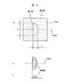
【0230】
図20は、以上の工程で得られた画素電極3070の凸部の形状を例示した図である。図20(a)は、凸部を形成するレジストを露光する際に使用するフォトマスク3000の開口部形状を示す図であり、図20(b)、(c)はそれぞれ、このフォトマスクを用いて形成した凸部の平面図と断面図である。
【0231】
図20に示す通り、現像工程により得られるレジストの平面形状を半円形のような対称軸を有する形状とし、対称軸3080Aに平行な方向に重力がかかるように、すなわち、半円形の円弧部を上にした状態で加熱処理することで、加熱処理後に円弧部と直線部とで傾斜角度分布が異なる非対称な断面形状が得られる。
【0232】
図21も、上記工程で得られた画素電極3070の凸部の形状を例示した図であり、図20に例示した凸部とはフォトマスク3000の開口部形状が異なる。具体的には開口部の直線部の長さL2は等しいままで、円弧部の長さL1を図20に例示した場合に比べて小さくした場合を例示する。
【0233】
図21(a)は、凸部を形成するレジストを露光する際に使用するフォトマスク3000の開口部形状を示す図であり、図21(b)、(c)はそれぞれ、このフォトマスクを用いて形成した凸部の平面図と断面図である。
【0234】
この場合も、現像工程により得られるレジストの断面形状を円弧部と直線部とで囲まれた非対称軸を有する形状とし、その対称軸3080Aに平行な方向に重力がかかるように、すなわち、半円形の円弧部を上にした状態で加熱処理することで、加熱処理後に円弧部と直線部とで傾斜角度分布が異なる断面形状が非対称な形状が得られる。
【0235】
この際、図20に例示した凸部とは、円弧部、直線部ともに傾斜角度の分布が異なり、傾斜角度は大きくなる。つまり、フォトマスクの開口部形状を変えて加熱処理する前の凸部の形状を変えることで、同じ条件で製造(加熱処理)しても円弧部の傾斜角度を同一面内で任意に変えることができる。
【0236】
なお、これら凸部の形状は、液晶表示装置100に斜めに入射する照明光800を観察者700の方向へ反射する形状とする必要がある。ここでは観察者700が通常、液晶表示装置100の表示を表示面垂線方向、もしくはその近傍から観察することが多いことを鑑み、表示面に斜めに入射する照明光800を表示面垂線方向へ反射するよう構成した。
【0237】
また、上述の通り、本実施の形態例では照明装置200が液晶表示装置100の表示部横幅よりも長い面光源として作用し、液晶表示装置表示部の左右方向に関しては照明光の入射角度の分布はほぼ対称となる。
【0238】
従って、画素電極3070の凸部の対称軸が表示面上下方向と平行となるよう構成して表示面の左右方向には格別な指向性を付与しないようにした。つまり、凸部を成す半円形の対称軸を液晶表示装置の表示面上下方向と平行となるようにし、その円弧部が表示面上部を向くようにした。
【0239】
なお、本実施の形態例では加熱処理時の重力の方向を工夫することで、自重により円弧部の傾斜面面積を、直線部に比べて広くなるようにした。これは、照明装置からの照明光に対して有効な指向性反射面となる円弧部の傾斜面を、直線部に比べて広くして、明るさを向上する為である。
【0240】
図22は、画素電極3070の凸部形状を説明するための断面図である。この断面図は、画素電極3070の凸部の平面図における対称軸の位置での断面図である。
【0241】
ここで、照明光の表示面への入射角度をθ1、外界(空気)の屈折率をn1、液晶層3130と配向膜3060の屈折率差が小さくほぼ等しいとしてその屈折率をn2とし、円弧部の傾斜角度γの平均値をγmとした場合、γmは概ね
γm=(sin-1(sinθ1・n1/n2))/2 ………(数3)
となるように構成すればよい。
【0242】
本実施の形態例の機器では、図7に示す通り、液晶表示装置100表示面の上部に入射する照明光800の主光束の入射角度は約35°であり、表示面の下部に入射する照明光の主光束の入射角度は約63°となる。そこで、画素電極の凸部を形成する際に、露光工程で使用するフォトマスクの開口部の形状を表示面上部に相当する領域と、表示面下部に相当する領域とで連続的に変化させ、現像工程後、すなわち加熱処理前のレジストからなる複数の凸部の形状が表示面内で連続的に変化するようにして最終的に得られる画素電極の平均傾斜角度γmも表示面内で連続的に変化するようにした。
【0243】
つまり、表示部上部に対応する画素電極の凸部の平均傾斜角度γmは11°とし、表示面の下部の平均傾斜角度γmは18°として、表示面上部から下部へかけての画素電極の凸部の平均傾斜角度γmを11°から18°へ連続的に増加させることで表示面のどの位置であっても照明光が表示面垂線方向へより多く反射されるように構成した。
【0244】
なお、画素電極の凸部の高さは2μm以上とすると、これに入射する光の偏光状態の変化が大きくなり、表示のコントラスト比が下がることが実験から明らかとなった。そこで、画素電極の凸部の高さは2μmより低くすることが望ましく、ここでは画素電極の凸部の高さを約1μmとし、直線部長さL2は10μm、円弧部の長さL1を表示面内で4〜10μmと変化させた。
【0245】
ところで、反射型液晶表示装置は照明装置から出射し、所定の斜め方向から表示面に入射する光に対し、高い反射率、及びより高いコントラスト比が得られる構成とすることが画質向上の面から重要である。
【0246】
そこで、本実施の形態例では液晶表示装置を以下の条件で作成した。
液晶層3130は、上述の通り、誘電異方性が正のネマチック液晶にカイラル剤を0.1〜0.2%添加した液晶組成物で構成した。液晶層3130の厚さdは5μmとし、Δndを0.365μmとした。液晶層3130の液晶分子長軸は配向膜3210、及び3060に行った表面処理によって2枚の基板間で連続的に50°ねじれるように構成した。
【0247】
位相差板3020としては、Δndが0.18μmのポリカーボネートからなる位相差板を用いた。
【0248】
図23は、図17の液晶表示装置100の構成条件を説明するための図であり、観察者の方向から見た際の液晶表示装置各部の軸の方向を示す図である。
【0249】
図23に示す通り、本実施の形態例の液晶表示装置100は、偏光板3010の吸収軸の方位角を120°、位相差板3020の遅相軸の方位角を135°、透明基板3030側の液晶配向軸の方位角を65°、反射基板3100側の液晶配向軸の方位角を295°とした。
【0250】
上記構成により、本液晶表示装置100は、ノーマリーオープン特性が得られる。
【0251】
図24に、従来の指向性のない拡散反射部を備えた場合の、図23に示す構成条件で作成した液晶表示装置の特性を示す。図24は、液晶表示装置に異なる方位角から仰角45°で光を入射した際に、仰角0°方向、すなわち表示面垂線方向で得られる反射率と液晶層への印加電圧の関係を示した図である。
【0252】
図24から明らかな通り、本液晶表示装置の条件では照明装置からの照明光、すなわち方位角90°から斜めに入射する光に対して、最も高い反射率、及び最も高いコントラスト比が得られる。具体的にはコントラスト比は全方位から光が入射する場合に比べて2倍となり、反射率も1割弱向上する。
【0253】
本発明の液晶表示装置では、さらに反射部に指向性を付与することで、照明装置からの照明光に対しては観察者の方向により高い反射率が得られるので、従来の指向性のない拡散反射部を備える場合に比べて輝度が約3倍と飛躍的に明るい画像が得られる。
【0254】
すなわち、本発明の液晶表示装置では所定の位置に配置した照明装置からの照明光に対して、反射率や、コントラスト比が高くなる表示モード、及び条件を選択するようにしたので、照明装置使用時に外光を利用する場合よりも高品位な画質が得られるという効果がある。
【0255】
また、上記構成により、本実施の形態例においても、液晶表示装置の反射部は、その反射の指向性を表示面の各位置における照明光の光入射角度や、強さに応じて最適化して、所定位置に配置した照明装置からの照明光を観察者側へ均一に反射するように構成したので、明るく面内の均一性が高い表示が得られるという効果がある。
【0256】
この際、液晶表示装置の表面等の界面での正反射光の方向と、画像光の方向は異なるため、照明装置の像が観察されて画質が劣化することがないという効果もある。
【0257】
また、カラーフィルタを照明装置からの照明光の主光束の方位角に平行となる方向に連続的に形成したので、液晶表示装置に入射し、反射する光の一部が往路復路の行程で異なる色のカラーフィルターを通過して、吸収されることが抑えられるのでより明るい画像が得られるという効果がある。
【0258】
さらに、このような照明装置を設けた反射型液晶表示装置を備える機器は、明るい環境下では機器に備える照明装置を使用せずに外光のみで表示をみることができ、周囲の照明が暗い場合には機器に備えた照明装置を使用することで良好な視認性を確保できる。このため、周囲の環境によらずいつでも良好な視認性を確保できるとともに、必要な場合にのみ照明装置を用いることで機器全体の消費電力が低減できるという効果がある。
【0259】
また、本実施の形態例では、反射部を背面側の基板と液晶層との間に内蔵したため光の往路復路での位置のずれが小さくなり照明光が斜め入射するために生じる画質の劣化が抑えられて、明るく、色純度の高い表示ができるという効果がある。
【0260】
なお、本実施の形態例ではメルトフローレジストをパーターニングし、加熱処理することで指向性反射機能を実現する凹凸部を形成した。すなわち、フォトマスクの開口部形状と、加熱処理時の重力の方向を工夫して所望の形状の凸部を得た。しかし、本発明は、これに限定されるものではなく加熱処理時に重力を用いる変わりに、反射基板を回転させるなどして遠心力を加え、所望の凹凸部を形成するようにしても良いし、送風により所望の凹凸部を形成するようにしてもよい。或いは、スイッチング素子等を形成し、絶縁膜を塗布して表面を平坦化した反射基板に熱硬化樹脂を成膜し、前もって凹凸のパターンを形成した金型により凹凸形状を転写して、指向性反射機能を有する凹凸部を形成するようにしてもよい。
【0261】
上記実施の形態例では、照明装置の光源として冷陰極管を用いる場合を示したが、この他に小型、高発光効率、低発熱といった条件を満たす光源としてLED(Light Emitting Diodes)を用いても良い。
図25は、照明装置200の他の例の一部断面図である。また、図26は、図25の照明装置の概略構成を示す一部斜視図である。
【0262】
本照明装置200は、発光部であるLEDチップ4010と、これを覆う透明な樹脂からなるレンズ部4020とから構成される複数の整列配置されたLEDランプ4000と、LEDランプ4000からの出射光を照射対象に導くためのガイド部4040と、LEDランプ4000の前方に配置した拡散板4030とから構成される。
【0263】
LEDランプ4000としては、青色発光LEDと蛍光体とを組み合わせて白色発光を実現したLEDランプを用いることができる。例えば、商品名:NSPW310AS(日亜化学工業製)を複数個、液晶表示装置表示面の横幅と同等、或いは長くなるように一列に整列配置して用いるとよい。
【0264】
拡散板4030は、複数のLEDランプ4000から出射する光の角度分布や、光量分布を均一化する機能を有するもので、ポリエチレンテレフタレート等の高分子フィルムの表面に凹凸を形成したもの、或いはフィルム内部に気泡を混入して拡散性を持たせたもの、或いはアクリル等の透明部材中に白色顔料を分散させた乳白色部材等を使用することができる。
【0265】
ガイド部4040は、LEDランプ4000からの出射光を照射対象である液晶表示装置表示面にできるだけ過不足なく照明するための補助部材であり、内面が鏡面反射面、或いは拡散反射面で構成される枠状の部材である。また、ガイド部4040は照明装置200からの出射光が直接観察者へ向かうことを防ぐための遮光部材としての機能も有する。
【0266】
LEDランプ4000への電力供給は、機器本体部300に内蔵する電源から配線を介して供給される。
【0267】
上記構成により、複数のLEDランプ4000から出射した光は拡散板230に入射し、角度分布や光量分布が均一化された後、カイド部4040を介して照射対象である液晶表示装置100に向かう。この際、照明装置200は、液晶表示装置表示面の横幅と同等、或いは表示面横幅よりも長い面光源として作用し、少なくとも液晶表示装置表示面の左右方向に関しては入射角度の分布が対称で均一な照明が可能となる。
【0268】
本照明装置では光源としてLEDを用いることで、冷陰極管では必要となるインバーターが不要となり、機器本体の小型化に有利である。また、LEDは冷陰極管のように水銀を含有していないので環境にやさしいという特長もある。
【0269】
次に、本発明の他の実施の形態例に係わる反射型液晶表示装置、及びこれを備えた機器を、図面を参照しながら説明する。
【0270】
なお、前述した図1の実施の形態例と共通となる部分については詳しい説明は省略し、本実施の形態例の特有部分について詳述する。
【0271】
図27は、本発明の他の実施の形態例に係わる反射型液晶表示装置、およびそれを備えた情報機器の斜視図である。この機器2は、キーボード等の入力手段や、CPU及び信号処理回路等を筐体内に備えた本体部4001と、本体部4001を覆うことができ、蝶番構造を介して本体部4001に取付けられた開閉自在な蓋部4002と、蓋部4002に備えられた反射型液晶表示装置(以下、液晶表示装置と略す)4003と、蓋部4002に可動支持部4005を介して備え付けられた照明装置4004とから構成される。
【0272】
照明装置4004は、液晶表示装置4003の前方であり、かつその表示面からは離れた位置に光出射部を備えた照明装置であり、機器使用者が表示部を観察する際に邪魔にならない所定の位置から液晶パネル4003の表示面を照明するよう移動可能に配置される。
【0273】
つまり、照明装置4004は、液晶表示装置4003の表示面を表示面垂線方向からずれた斜めの方向から照明するように構成する。
【0274】
照明装置4004は、前述した照明装置200と同様の照明装置を用いればよい。つまり、光源として小型、高発光効率、低発熱といった条件を満たすものを用い、光源からの出射光を効率よく液晶表示装置4003に照射する構成とする。
【0275】
光源としては、冷陰極管や熱陰極管等の蛍光灯、或いはLED(Light Emitting Diodes)、EL(Electroluminescence)等の発光素子を用いることができる。この際、照明装置4004は、液晶表示装置4003表示部の横幅よりも長い幅を有する面光源となるように構成し、少なくとも液晶表示装置表示部の左右方向に関しては光入射角度が対称で、均一な照明が可能となる照明装置を用いる。
【0276】
液晶表示装置4003も、前述した反射型液晶表示装置100と同様の構造の反射型液晶表示装置を使用し、その表面側に図示しないタッチパネルを備えて、ペン入力が可能となるようにしても良い。
【0277】
液晶表示装置4003は、照明装置4004から出射し、所定の斜め方向から表示面に入射する光に対し、高い反射率、及びより高いコントラスト比が得られる表示モード及び構成を選択する。
【0278】
さらに、液晶表示装置4003の反射部は照明装置4004から出射し、斜め方向から表示面に入射する光を観察者の方向へ反射するような指向性を有し、この指向性を表示面の各位置における照明光の光入射角度や、強さに応じて最適化することで表示面内で均一な表示を得るようにしたものを使用する。
【0279】
図28は、機器2の概略を示す側面図であり、携帯可能状態から使用可能状態への形態の変化を説明するための図である。図示の通り、機器2は携帯可能状態(図28(a)参照)では薄い箱型をしており、持ち運びに便利な形態となっている。
【0280】
使用する場合には、まず蓋部4002を開き、画像表示部である反射型液晶表示装置を観察可能とする(図28(b)参照)。周囲が明るい環境下であればこの状態で画像は十分に観察できるので本機器は使用可能である。暗い環境下であれば機器2の蓋部4002に備えられた照明装置4004を所定の位置に移動して、液晶表示装置4003を前方から照明することになる。
【0281】
本実施の形態例では、照明装置4004は、蓋部4002の両サイドに備えられた2本の棒状の可動支持部4005を介して機器に備えつけられている。可動支持部4005と蓋部4002、及び可動支持部4005と照明装置4004とはそれぞれ回転軸部4006、及び回転軸部4007において回転可能に接続されている。また、可動支持部4005は、回転軸部4006を軸として蓋部4002に対してスライド可能な構造となっている。
【0282】
携帯可能状態、もしくは明るい環境下で照明装置4002を必要としない場合、照明装置4004は本体部4001、或いは蓋部4002と一体化し、収納された状態であるため携帯性や操作性を阻害しない構成となっている(図28(a)、(b)参照)。
【0283】
照明装置4004を使用する場合は、まず、回転軸部4006を中心に可動支持部4005をスライドさせ、さらに回転して、照明装置4004を液晶表示装置前方に移動する。さらに、回転軸部4007を中心に照明装置4004を回転して、照明装置4004の光出射部を液晶表示装置4003に向ければ反射型液晶表示装置を照明することが可能となる(図2(c)参照)。この際、照明装置4004は、可動支持部4005、及び回転軸部4006、回転軸部4007に備えられる位置決め機構により液晶表示装置4003に対して所定の位置に固定される。
【0284】
上記構成により、照明装置4004は、液晶表示装置前方の所定位置に配置したり、本体部4001、或いは蓋部4002と一体化した収納状態とすることを必要に応じて行うことができる構造となっている。
【0285】
本実施の形態例においても、前述した実施の形態例と同様、照明装置4004として液晶表示装置4003の前方であり、かつその表示面からは離れた位置に光出射部を備えた照明装置4004を移動可能に備え、機器使用者が表示部を観察する際に邪魔にならない位置から液晶表示装置4003の表示面を照明するように構成した。つまり、照明装置4004は、液晶表示装置4003の表示面直上部を除く位置で、表示面垂線方向からずれた斜めの方向から表示面を照明するように構成した。
【0286】
このため、導光体式前方照明装置のように導光体等の光損失の原因となるような複雑な光学系を必要としないため損失の少ない効率の良い照明ができる。また、液晶表示装置の表示面上に導光体等の付加部材を配置しないため、付加部材による表示の劣化や、タッチパネル使用時の視差といった導光体式前方照明装置特有の課題が回避できる。
【0287】
また、投写式前方照明装置では照明光の強さや照明光の入射角度が表示面の位置により異なり、表示面内で均一な明るさの表示を得ることが困難である。
【0288】
しかし、本実施の形態例に係る液晶表示装置4003の反射部は、その反射の指向性を表示面の各位置における照明光の光入射角度や、強さに応じて最適化することで、所定の位置に配置した照明装置4004から出射し、表示面に斜めに入射する照明光を観察者側へ均一に反射するように構成したので、明るく面内の均一性が高い表示が得られるという効果がある。
【0289】
この際、図28(c)に例示する通り、液晶表示装置4003の表面等の界面での正反射光1000の方向と、画像光900の方向が異なるため、照明装置4004の正反射像が観察されて画質が劣化することがない。
【0290】
さらに、液晶表示装置4003は、所定の位置に配置した照明装置4004からの照明光に対して、反射率や、コントラスト比が高くなる表示モードや条件を選択することで、照明装置使用時には外光を利用する場合よりも高品位な画質が得られるという効果もある。
【0291】
また、照明装置4004を、液晶表示装置4003の上部に配置するように構成することで、以下の効果も得られる。
【0292】
液晶表示装置4003は、周囲が明るい環境下では照明装置4004を使用することなく外光のみでの使用が可能である。この際、外光の大部分は液晶表示装置4003の上方から入射する。特に、本実施の形態例のように、キーボードを有する機器では液晶表示装置4003の下方から外光が入射することは少なく、外光の大部分は液晶表示装置4003の上方から入射する。
【0293】
従って、照明装置使用時の照明装置4004の配置位置を液晶表示装置4003の上部とし、上方から入射する光を観察者側へ反射する指向性の反射部を構成する。これにより、液晶表示装置4003の上方から入射する外光を効率よく観察者側へ反射できるので、照明装置不使用時にも明るい画像が得られるという効果がある。
【0294】
また、暗闇の中で作業する場合は、本実施の形態例の通り、上部に配置した照明装置4004からの照明光のうち液晶表示装置4003の表面等で正反射した光がキーボードや手元を照明することになり、作業性が上がるといった効果もある。
【0295】
さらに、このような照明装置を設けた反射型液晶表示装置を備える機器は、明るい環境下では機器に備える照明装置を使用せずに外光のみで表示をみることができ、周囲の照明が暗い場合には機器に備えた照明装置を使用することで良好な視認性を確保できる。このため、周囲の環境によらず、いつでも良好な視認性を確保できるとともに、必要な場合にのみ照明装置を用いることで機器全体の消費電力が低減できるという効果がある。
【0296】
本実施の形態例では、特に、照明装置4004を可動支持部4005を介して液晶表示装置4003を備える蓋部4002に設け、照明装置4004使用時の照明装置4004の位置を固定するようにした。
【0297】
このため、機器使用者が液晶表示装置4003の角度を変えたるために蓋部4002の角度を変えても、液晶表示装置4003と照明装置4004との相対的な位置関係は変わらないので、良好な画質を得るための照明装置4004の位置の調整が容易になり、使い勝手が向上するという効果がある。
【0298】
次に、本発明の更に他の実施の形態例に係わる反射型液晶表示装置、及びこれを備えた機器を、図面を参照しながら説明する。
【0299】
なお、前述した実施の形態例と共通となる部分については詳しい説明は省略し、本実施の形態例の特有部分について詳述する。
【0300】
図29は、本発明の更に他の実施の形態例に係わる反射型液晶表示装置、およびそれを備えた情報機器の斜視図である。この機器3は、CPU、信号処理回路等を筐体内部に実装した本体部5002と、本体部5002に蝶番構造を介して取り付けられた本体部5002を覆うことができる開閉可能な蓋部5003と、本体部5002に備え付けられた反射型液晶表示装置(以下、液晶表示装置と略す)5001と、蓋部5003に備え付けられた照明装置5004とから構成される。
【0301】
液晶表示装置5001の表面には図示しないタッチパネルを備え、液晶表示装置5001に表示されるボタン等の画像の位置を専用の入力用ペン等により押さえることで処理内容等の入力ができる構成とする。
【0302】
照明装置5004は蓋部5003に備えられ、液晶表示装置5001の前方であり、かつその表示面からは離れた位置に光出射部を備え、機器使用者が表示部を観察する際に邪魔にならない位置から反射型液晶表示装置5001の表示面を照明するよう配置される。
【0303】
照明装置5004の光源としては前述と同様の光源、つまり小型、高発光効率、低発熱といった条件を満たすものを用いればよく、冷陰極管や熱陰極管等の蛍光灯、或いはLED(Light Emitting Diodes)、EL(Electroluminescence)等の発光素子を用いることができる。
【0304】
また、照明装置5004としては、液晶表示装置5001の表示部の横幅よりも長い幅の光出射部を有する面光源を構成し、少なくとも液晶表示装置表示部の左右方向に関しては略均一な照明が可能となる照明装置を用いる。
【0305】
液晶表示装置5001としては、前述した液晶表示装置と同様の構成の反射型液晶表示装置を使用すれば良い。すなわち、液晶表示装置5001は照明装置5004から出射し、所定の斜め方向から表示面に入射する光に対し、高い反射率、及びより高いコントラスト比が得られる構成とする。
【0306】
さらに、液晶表示装置5001の反射部は、照明装置5004から出射し斜め方向から表示面に入射する光を観察者の方向へ反射するような指向性を有し、この指向性を表示面の各位置における照明光の光入射角度や、強さに応じて最適化することで表示面内で均一な表示を得るようにしたものを使用する。
【0307】
本実施の形態例においても、上記実施の形態例と同様、液晶表示装置5001の表示面上に導光体等の付加部材を配置しないため、付加部材による表示の劣化のない見やすい画像が得られ、視差の小さい自然なペン入力が実現できる。
【0308】
また、液晶表示装置5001の反射部は、その反射の指向性を表示面の各位置における照明光の光入射角度や、強さに応じて最適化することで、所定の位置に配置した照明装置5004からの照明光を観察者側へ均一に反射するように構成したので、明るく面内の均一性が高い表示が得られるという効果がある。
【0309】
さらに、液晶表示装置5001は、所定の位置に配置した照明装置5004からの照明光に対して、反射率や、コントラスト比が高くなる表示モードや条件を選択したので、外光を利用する場合よりも高品位な画質が得られるという効果もある。
【0310】
さらに、このような照明装置を設けた反射型液晶表示装置を備える機器は明るい環境下では機器に備える照明装置を使用せずに外光のみで表示をみることができ、周囲の照明が暗い場合には機器に備えた照明装置を使用することで良好な視認性を確保できる。このため、周囲の環境によらず、いつでも良好な視認性を確保できるとともに、必要な場合にのみ照明装置を用いることで機器全体の消費電力が低減できるという効果がある。
【0311】
本実施の形態例では、特に照明装置5004が蓋部5003に内蔵されており、蓋部5003を開けるという動作のみで、照明装置5004を所定位置に配置できるため使い勝手が向上するという効果がある。
【0312】
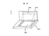
図30は、本発明の更に他の実施の形態例に係わる反射型液晶表示装置、およびそれを備えた情報機器の斜視図である。この機器4は、信号処理回路等を筐体内部に実装した本体部6001と、本体部6001に備え付けられた反射型液晶表示装置(以下、液晶表示装置と略す)6002と、本体部6001に着脱可能な照明装置5とから構成される。
【0313】
照明装置5は、光源と光出射部6003と支柱6004と支柱台座部6005等から構成される。支柱台座6005には例えば凹形状の溝が設けられており、これを本体部6001に設けられた凸部にはめ込むことで本体部6001の所定位置に固定できる構成とする。また、支柱台座部6005には電極部が設けられ、本体部6001に装着した際、照明装置5を点灯するための電力を本体部6001から受け取ることができる構成とする。
【0314】
支柱6004は、照明装置5の光出射部が液晶表示装置6002の前方であり、かつその表示面から離れた所定の位置に配置されるように構成する。
【0315】
照明装置5の光源としては前述と同様の光源、つまり小型、高発光効率、低発熱といった条件を満たすものを用いればよく、ここでは小さな光出射部を低コストで実現できるLED(Light Emitting Diodes)を用いた。
【0316】
なお、一般的には照明装置5の光出射部を大きく構成すれば、照射対称である液晶表示装置6002を均一に照明することが容易になるため、より均一な明るさの表示が得られる。しかし、例えば携帯用のゲーム機器等のように、軽量、低コストといった要求を重視する場合には、本実施の形態例のように光出射部の小さな照明装置5を選択してもよい。
【0317】
液晶表示装置6002としては、前述した実施の形態例と同様の反射型液晶表示装置を使用すれば良い。すなわち、液晶表示装置6002は照明装置5から出射し、所定の斜め方向から表示面に入射する光に対し、高い反射率、及びより高いコントラスト比が得られる表示モード及び構成を選択する。
【0318】
さらに、液晶表示装置6002の反射部は、照明装置5から出射し斜め方向から表示面に入射する光を観察者の方向へ反射するような指向性を有し、この指向性を表示面の各位置における照明光の光入射角度や、強さに応じて最適化することで表示面内で均一な表示を得るようにしたものを使用する。
【0319】
本実施の形態例では、照明装置が小さく、表示面左右方向でも位置毎に光入射角度が異なるので、反射部は前述した実施の形態例の様に表示面の上下方向でのみその反射の指向性を変えるのではなく、左右方向も考慮して2次元的に反射の指向性を制御する必要がある。
【0320】
例えば、反射部を液晶表示装置6002に内蔵した複数のランダム配置した凸部、或いは凹部を有する反射体で構成し、凸部、或いは凹部の平面形状を半円形などの対称軸を有する形状とし、その対称軸を表示面の各位置における照明光の主光束が入射する方位角と平行とし、円弧部を照明光の入射方向に向けるようにすればよい。
【0321】
本実施の形態例においても、前述した実施の形態例と同様、液晶表示装置6002の反射部は、その反射の指向性を表示面の各位置における照明光の光入射角度や、強さに応じて最適化することで、所定の位置に配置した照明装置からの照明光を観察者側へ均一に反射するように構成したので、明るく面内の均一性が高い表示が得られるなどの効果がある。
【0322】
また、このような照明装置を設けた反射型液晶表示装置を備える機器は明るい環境下では機器に備える照明装置を使用せずに外光のみで表示をみることができ、周囲の照明が暗い場合には機器に備えた照明装置を使用することで良好な視認性を確保できる。このため、周囲の環境によらずいつでも良好な視認性を確保できるとともに、必要な場合にのみ照明装置を用いることで機器全体の消費電力が低減できるという効果がある。
【0323】
本実施の形態例では、特に照明装置5を着脱可能としたため、照明装置5が不要な場合に照明装置5を取り外すことで、機器が小型、軽量となり、持ち運びや、手に持っての使用が容易になるという効果がある。
【0324】
【発明の効果】
上述の通り本発明の反射型液晶表示装置及びそれを備えた機器では、反射型液晶表示装置の前方で、かつその表示面から離れた位置に光出射部を備えた照明装置を移動可能に備え、機器使用者が表示部を観察する際に邪魔にならない位置から反射型液晶表示装置の表示面を照明するように構成した。
【0325】
つまり、照明装置は、反射型液晶表示装置の表示面直上部を除く位置で、表示面垂線方向からずれた斜めの方向から表示面を照明するように構成した。
【0326】
このため、導光体等の光損失の原因となるような複雑な光学系を必要としないため、光損失の少ない効率の良い照明ができる。さらに、液晶表示装置の表示面上に導光体等の付加部材を配置しないため、付加部材による表示の劣化のない見やすい画像が得られ、視差の少ない自然なペン入力が可能になる。
【0327】
また、照明装置を機器本体に備え、反射型液晶表示装置との位置関係を固定することで、反射型液晶表示装置表示面の各位置に入射する照明光の強度や入射角度が定まる。これに対応して反射型液晶表示装置の反射手段は、その反射特性(反射角度、指向性)を表示面の各位置における照明光の入射角度や、強さに応じて最適化し、その反射特性を表示面内で異なるよう構成する。つまり、反射手段の反射特性を照明光の入射角度や、強さに応じて最適化し、照明装置からの照明光を観察者側へ均一に反射するように構成することで、明るく面内の均一性が高い表示が得られるという効果がある。
【0328】
この際、液晶表示装置の表面等の界面での正反射光の方向と、画像光の方向は異なるため、照明装置の像が観察されて画質が劣化することがない。
【0329】
さらに、液晶表示装置は所定の位置に配置した照明装置からの照明光に対して、反射率や、コントラスト比が高くなる表示モードや条件を選択することで、照明装置使用時に外光を利用する場合よりも高品位な画質が得られるという効果もある。
【0330】
また、照明装置を液晶表示装置の上部に配置するように構成することで以下の効果も得られる。
【0331】
反射型液晶表示装置は、周囲が明るい環境下では照明装置を使用することなく外光のみでの使用が可能である。この際、外光の大部分は液晶表示装置の上方から入射する。特にキーボードを有する機器では液晶表示装置の下方から外光が入射することはなく、外光の大部分は液晶表示装置の上方から入射する。
【0332】
従って、照明装置使用時の照明装置の配置位置を液晶表示装置の上部とし、上方から入射する光に対応した反射特性(指向性)の反射部を構成することで、照明装置不使用時に液晶表示装置の上方から入射する外光が効率よく観察者側へ反射され、明るい画像が得られるという効果がある。
【0333】
さらに、暗闇の中で作業する場合は、上部に配置した照明装置からの照明光のうち液晶表示装置の表面等で正反射した光がキーボードや手元を照明することになり作業性が上がるという効果もある。
【0334】
また、このような照明装置を設けた反射型液晶表示装置を備える機器は、明るい環境下では機器に備える照明装置を使用せずに外光のみで表示をみることができ、周囲の照明が暗い場合には機器に備えた照明装置を使用することで良好な視認性を確保できる。このため、周囲の環境によらず、いつでも良好な視認性を確保できるとともに、必要な場合にのみ照明装置を用いることで機器全体の消費電力が低減できるという効果がある。
【0335】
また、液晶表示装置に備えるカラーフィルタを、照明装置からの照明光の主光束の方位角に平行となる方向に連続的に形成したことで、液晶表示装置に入射し、反射する光の一部が往路復路の行程で異なる色のカラーフィルターを通過し、吸収されることが抑制されてより明るく、色純度の高い画像が得られるという効果がある。
【0336】
また、液晶表示装置の反射手段を、背面側の基板と液晶層との間に内蔵した場合は、光の往路復路での位置のずれが小さくなり照明光が斜め入射するために生じる画質の劣化が抑えられて、明るく、色純度の高い表示ができるという効果がある。
【図面の簡単な説明】
【図1】本発明の一実施の形態例に係わる反射型液晶表示装置及びそれを備えた携帯情報機器の斜視図である。
【図2】図1の機器の略側面図である。
【図3】図1の照明装置の一例の概略構成を示す一部斜視図である。
【図4】図3の照明装置の一部断面図である。
【図5】図1の液晶表示装置の一例の概略構成を示す一部断面図である。
【図6】図5の液晶表示装置の反射部をなす微小傾斜反射面の説明図である。
【図7】図1の携帯情報機器の側面図である。
【図8】図5の液晶表示装置の構成条件の説明図である。
【図9】本明細書における方位角と仰角の定義の説明図である。
【図10】図5の液晶表示装置の画像形成部の特性を示す図である。
【図11】液晶表示装置における「暗表示部の影」の説明図である。
【図12】図5の液晶表示装置のカラーフィルタの配置の説明図である。
【図13】図5の液晶表示装置の反射部の一例の概略構成を示す正面図である。
【図14】本発明の他の実施の形態例に係る液晶表示装置の一部概略断面図である。
【図15】本発明の更に他の実施の形態例に係る液晶表示装置の一部概略断面図である。
【図16】図15の液晶表示装置の構成条件の説明図である。
【図17】本発明の更に他の実施の形態例に係る液晶表示装置の一部概略断面図である。
【図18】図17の液晶表示装置の微細な凸部を備えた画素電極の製造工程を説明するための一部断面図である。
【図19】図18の画素電極の凸部の製造に使用するフォトマスクの一例を示す一部正面図である。
【図20】図18の画素電極の凸部の形状の一例を示す図である。
【図21】図18の画素電極の凸部の形状の他の例を示す図である。
【図22】図18の画素電極の凸部形状の説明図である。
【図23】図17の液晶表示装置の構成条件の説明図である。
【図24】図17の液晶表示装置の特性を示す図である。
【図25】図1の照明装置の他の例の一部断面図である。
【図26】図25の照明装置の概略構成を示す一部斜視図である。
【図27】本発明の他の実施の形態例に係わる反射型液晶表示装置、およびそれを備えた情報機器の斜視図である。
【図28】図27の機器の概略構成を示す側面図である。
【図29】本発明の更に他の実施の形態例に係わる反射型液晶表示装置、およびそれを備えた情報機器の斜視図である。
【図30】本発明の更に他の実施の形態例に係わる反射型液晶表示装置、およびそれを備えた情報機器の斜視図である。
【符号の説明】
1,2,3,4…機器、5,200,4004,5004…照明装置、100,4003,5001,6002…反射型液晶表示装置、101…画像形成部、110…第1の透明基板、112,122,2060,2090,3060,3210…配向膜、113,121,2070,2100,3050…透明電極、120…第2の透明基板、130,2080,3130…液晶層、170,180,2010,3010…偏光板、1602020,2030,3020…位相差板、190,2211…反射部、191,2210…微小傾斜反射面、192,2221…光拡散層、193,2220…透明粒子、194,2230…透明媒体、210…光源、300,4001,5002,6001…本体部、400,4005…可動支持部、500,4002,5003…蓋部、700…観察者、900…画像光、1000…正反射光、1110…ホログラム、2040,3030…透明基板、2050,3040…カラーフィルタ、2200,3100…反射基板、2300,3090…絶縁層、3070…画素電極、3200…絶縁層を形成し平坦化した反射基板、401,405,4006,4007…回転軸部、6003…光出射部[0001]
BACKGROUND OF THE INVENTION
The present invention relates to a reflective liquid crystal display device and devices such as a portable game machine, a portable information terminal, and a mobile computer equipped with the same.
[0002]
[Prior art]
In general, a liquid crystal display device is a non-luminous display that displays an image by adjusting the amount of transmitted light, unlike a self-luminous display such as a CRT (Cathode Ray Tube) or a PDP (Plasma Display Panel). . Liquid crystal display devices can be roughly classified into a transmission type and a reflection type.
[0003]
The transmissive liquid crystal display device includes an illumination device on the back side of the display surface, and the visibility of the display image is enhanced by illumination light from the illumination device.
[0004]
On the other hand, a reflective liquid crystal display device is provided with a reflective portion on the back side of a liquid crystal layer and performs display using ambient light. In a bright environment, a specific light source is not required and power consumption is reduced. There is a feature that you can. Especially in a very bright place where it is exposed to direct sunlight, a light emitting display or a transmissive liquid crystal display device can hardly see the display due to external light reflection on the surface of the display surface, whereas a reflective liquid crystal display device is clearer. There is also an advantage that it looks like.
[0005]
For this reason, the reflective liquid crystal display device is employed in portable devices such as portable information terminals and mobile computers for which low power consumption is desired, or digital cameras that are expected to be used outdoors.
[0006]
However, since the reflective liquid crystal display device performs display using ambient light, its visibility is deteriorated in a dark environment, and there is a problem that the display cannot be recognized at all particularly in the dark such as at night. For this reason, some auxiliary illumination device is desired in preparation for a case where sufficient ambient light cannot be obtained with a reflection type liquid crystal display device and a device including the reflection type liquid crystal display device as a display unit.
[0007]
Conventionally, various lighting devices have been proposed as such lighting devices.
Conventionally proposed illumination devices can be broadly divided into a transparent light guide disposed so as to cover the entire display surface of a reflective liquid crystal display device, and a light source disposed at an end of the light guide. The illumination device that irradiates the display surface with the light emitted from the light guide (hereinafter referred to as a light guide-type front illumination device), and in front of the reflective liquid crystal display device and away from the display surface There is an illuminating device (hereinafter referred to as a projection-type front illuminating device) in which a light source is arranged to directly irradiate a display surface with light source light.
[0008]
The light guide type front illumination device is disclosed in, for example, SID 95 DIGEST p375-378, Japanese Patent Laid-Open No. 5-158034, Japanese Patent Laid-Open No. 10-142601, and the like. In either case, light emitted from a light source disposed at the end of the light guide is introduced into the light guide, and out of the light propagating through the light guide, a protrusion or prism formed on the front or back surface of the light guide In this configuration, light incident on the portion (inclined portion) is emitted toward the display surface of the liquid crystal display device and illuminated.
[0009]
Further, display devices or devices provided with a projection type front illumination device are disclosed in, for example, Japanese Patent Application Laid-Open Nos. 4-70626, 9-211448, and 10-246886. In any case, a light source is provided on a device main body provided with a reflective liquid crystal display device, a support provided on the device main body, or a lid for covering the display unit, and the display unit is directly illuminated from the front. .
[0010]
In a device equipped with a reflective liquid crystal display device having such a lighting device, the display can be seen only with outside light without using the lighting device in a bright environment, and when the surrounding lighting is dark, the lighting device By using this, good visibility is ensured.
[0011]
[Problems to be solved by the invention]
A light guide-type front illumination device is configured to reduce the light source light due to light loss when light emitted from a light source enters the light guide, or leakage of light propagating through the light guide in a different direction from the reflective liquid crystal display device. The utilization efficiency is as low as 60% or less, and there is a problem that power consumption increases when the lighting device is used.
[0012]
Further, there is a problem in that the display is deteriorated because structures such as grooves and microprisms for directing light propagating through the light guide to the liquid crystal display device side exist on the display surface.
[0013]
In addition, in a device having a touch panel on the front surface of the reflective liquid crystal display device, if there is a light guide on the display surface, the position indicated by the input pen and the display of the liquid crystal display device due to its thickness There is a problem that a large parallax (displacement) occurs and the usability deteriorates.
[0014]
On the other hand, since the projection-type front illumination device does not require a complicated optical system that causes light loss such as a light guide, efficient illumination can be expected. Furthermore, since no additional member such as a light guide is disposed on the display surface, problems peculiar to the light guide type front illumination device such as display deterioration and parallax when using the touch panel can be avoided.
[0015]
However, when the projection type front illumination device includes the illumination device in the apparatus body, the distance between the illumination device and the reflection type liquid crystal display device cannot be sufficiently separated, so that the display surface of the reflection type liquid crystal display device can be illuminated uniformly. Have difficulty. That is, since the distance from the light source (or the light emitting unit) and the angle formed by the light source and the display surface (the angle of the line connecting the light source and the display surface) differ depending on the position of the display surface, the intensity of illumination light from the illumination device is increased. In addition, the light incident angle varies depending on the position of the display surface of the liquid crystal display device, and the display surface cannot be illuminated uniformly, and there is a problem that it is difficult to obtain a display with uniform brightness within the display surface.
[0016]
In addition, in a projection front illumination device, the direction in which a bright display is obtained matches the direction of interface reflection on the display surface of the reflective liquid crystal display device of the illumination light. There is a problem that the output part is reflected and the display becomes difficult to see.
[0017]
Further, when two polarizing plates are used as the reflective liquid crystal display device and the reflective portion is externally attached to the back surface thereof, there is a problem that “shadow of dark display portion” is generated when the illumination light is incident obliquely. Here, the “shadow of the dark display part” is a phenomenon in which the brightness of the bright display part adjacent to the dark display part is lowered, and it is as if the shadow of the dark display part appears.
[0018]
An object of the present invention is to provide a reflective liquid crystal display device capable of obtaining a bright and uniform display without display deterioration, parallax when using a touch panel, and reflection of a light source or a lighting device, and an apparatus including the same. There is.
[0019]
[Means for Solving the Problems]
In order to achieve the above object, the present invention provides a pair of substrates bonded via a predetermined gap and at least one of which is transparent, a liquid crystal layer provided between the pair of substrates, and a back side of the liquid crystal layer. In the reflection type liquid crystal display device having the reflection means provided, the reflection meansA reflective surface, and the angle of the reflective surface continuously changes within the display surface, and the reflective means has a specular reflection component of the reflective surface whose magnitude is from the lower display surface toward the upper display surface. Continuously smaller It is comprised as follows.
[0020]
Further, the present invention provides a pair of substrates that are joined via a predetermined gap and at least one of which is transparent, a liquid crystal layer provided between the pair of substrates, and a reflecting means provided on a back side of the liquid crystal layer. And a reflection type liquid crystal display device including an illumination device that irradiates display light with illumination light, wherein the illumination device is disposed in front of the display surface and from a direction different from a normal direction of the display surface A light emitting unit for illuminating the display surface;A reflective surface, and the angle of the reflective surface continuously changes within the display surface, and the reflective means has a specular reflection component of the reflective surface whose magnitude is from the lower display surface toward the upper display surface. Continuously smaller It is comprised as follows.
[0021]
With the above configuration, the reflective liquid crystal display device of the present invention does not require a complicated optical system that causes light loss, such as a light guide, and therefore can perform efficient illumination with little light loss.
[0022]
Further, since no additional member such as a light guide is disposed on the display surface of the reflective liquid crystal display device, an easy-to-view image without display deterioration caused by the additional member is obtained, and natural pen input with less parallax is possible.
[0023]
Further, the reflection means of the reflective liquid crystal display device isThere is a reflective surface, and the angle of the reflective surface is continuously changing in the display surface, and the reflection means is such that the size of the regular reflection component of the reflective surface is continuous from the lower display surface to the upper display surface. It is comprised so that it may become small. That is, the reflection means of the reflective liquid crystal display device is: The reflection angle and directivity are optimized according to the light incident angle and intensity of the illumination light at each position on the display surface. The light is emitted from a lighting device placed at a predetermined position and incident obliquely on the display surface. Since the illumination light is configured to be uniformly reflected toward the viewer side, a bright display with high uniformity within the surface can be obtained. At this time, since the direction of the regular reflection light at the interface such as the surface of the reflective liquid crystal display device and the direction of the image light are different, the image of the illumination device is observed and the image quality is not deteriorated.
[0024]
As the reflection means of the reflective liquid crystal display device, the following three reflection means can be roughly used.
[0025]
(1) Reflecting means comprising a plurality of reflecting surfaces inclined with respect to the display surface and light diffusing means for diffusing light reflected by the reflecting surfaces.
[0026]
(2) It has a reflective surface on which a plurality of concave portions, or a plurality of convex portions, or a plurality of concave and convex portions are formed.Each Convex part, alsoEach The concavo-convex portion has a cross-sectional shape having at least one asymmetric axis and one symmetric axis.Including arc Reflecting means having a planar shape and a symmetry axis set to be parallel to the azimuth direction of the main light flux of incident light.
[0027]
(3) Reflecting means comprising a hologram.
[0028]
Another feature of the present invention is that a polarizing plate and a retardation plate are provided on the front surface of the substrate on the display surface side so that the transmittance of dark display becomes high with respect to illumination light incident obliquely from the illumination device. And a polarizing plate is disposed between the reflecting means and the substrate on the reflecting means side.The azimuth angle of the absorption axis of the polarizing plate on the display surface side is 255 °, the azimuth angle of the slow axis of the retardation plate is 185 °, and the azimuth angle of the liquid crystal alignment axis on the substrate side on the display surface side is 105 °, the azimuth angle of the liquid crystal alignment axis on the substrate side on the reflecting means side is 165 °, and the azimuth angle of the absorption axis of the polarizing plate on the reflecting means side is 120 °. There is.
[0029]
With the above configuration, even if illumination light that is incident on the display surface obliquely passes through the dark display part, the transmittance is high, so the occurrence of “shadows on the dark display part” appearing in the adjacent bright display part is eliminated, and visual recognition is possible. A good image can be obtained.
[0030]
Another feature of the present invention is that the reflecting means is provided between the liquid crystal layer and the substrate located on the back side of the liquid crystal layer of the pair of substrates.
[0031]
In this case, the illumination light incident on the reflective liquid crystal display device passes through the liquid crystal layer, is reflected by the reflecting means, passes through the liquid crystal layer again, and exits from the reflective liquid crystal display device. Since the deviation is small, image quality degradation caused by the oblique incidence of illumination light is suppressed, and a bright display with high color purity can be achieved.
[0032]
Another feature of the present invention is that a polarizing plate is disposed on the front surface of the substrate on the display surface side, the incident direction of light from which the reflective liquid crystal display device obtains a high reflectance and a high contrast ratio, and the illumination The incident light direction from the device is configured so as to substantially match the incident direction.
In other words, the reflection type liquid crystal display device of the single polarizing plate has a display mode and a condition in which the reflectance and the contrast ratio are high with respect to the illumination light from the illumination device arranged at a predetermined position. In use, a higher quality image can be obtained than when using external light.
[0033]
Another feature of the present invention is that a light emitting portion of the illumination device is disposed above the reflective liquid crystal display device.
[0034]
Thereby, the following effects are acquired. That is, the reflective liquid crystal display device can be used only with outside light without using an illumination device in an environment where the surroundings are bright. At this time, most of the outside light enters from above the reflective liquid crystal display device. In particular, in a device having a keyboard, external light rarely enters from below the reflective liquid crystal display device, and most of the external light enters from above the liquid crystal display device.
[0035]
Therefore, the arrangement position of the illuminating device when the illuminating device is used is the upper part of the liquid crystal display device, and a reflecting portion corresponding to light incident from above is configured to enter from above the reflective liquid crystal display device when not using the illuminating device. Since external light is efficiently reflected to the viewer side, there is an effect that a bright image can be obtained.
[0036]
In addition, when working in the dark, the light reflected from the surface of the reflective liquid crystal display device, etc. out of the illumination light from the lighting device placed above illuminates the keyboard and hand, improving workability. There is also.
[0037]
Another feature of the present invention is that the light emitting portion has a width equal to or greater than a width of the reflective liquid crystal display device, and is disposed in front of, above or below the display surface. It is to be done.
[0038]
Another feature of the present invention is that a color filter is disposed between the substrate on the display surface side and the liquid crystal layer, and the direction is parallel to the azimuth angle direction of the main luminous flux of illumination light from the illumination device. It is that it was formed continuously.
[0039]
Here, the illumination light emitted from the illumination device enters the reflective liquid crystal display device at various angles. Therefore, the light in the direction in which the intensity of the illumination light is strongest is hereinafter referred to as the main light flux (direction) of the illumination light.
[0040]
As described above, if the color filter arranged in the reflective liquid crystal display device is continuously formed in a direction parallel to the azimuth direction of the main light flux of the illumination light from the illumination device, the illumination light is reflected. Is brighter and more pure, because part of the illumination light that is incident obliquely on the LCD and reflected by the reflecting means passes through the color filters of different colors and is absorbed during the outward path. The effect is that a high-quality image can be obtained.
[0041]
The present invention also provides a reflective liquid crystal display device that modulates the amount of reflected light of incident light and outputs the image, an illumination device that irradiates illumination light onto a display surface of the reflective liquid crystal display device, and the reflective liquid crystal display. In an apparatus including a device and a device main body that controls the lighting device, and a movable support portion that is provided in the device main body and supports the lighting device, the reflective liquid crystal display device is bonded via a predetermined gap. A pair of substrates, at least one of which is transparent, a liquid crystal layer provided between the pair of substrates, and a reflecting means provided on the back side of the liquid crystal layer, the reflecting meansA reflective surface, and the angle of the reflective surface continuously changes within the display surface, and the reflective means has a specular reflection component of the reflective surface whose magnitude is from the lower display surface toward the upper display surface. Continuously smaller The lighting device has a light emitting unit that illuminates the display surface from a direction different from the normal direction of the display surface, and is movable forward of the display surface via the movable support unit. It is arranged to be possible.
[0042]
The present invention also provides a reflective liquid crystal display device that modulates the amount of reflected light of incident light and outputs the image, an illumination device that irradiates illumination light onto a display surface of the reflective liquid crystal display device, and the reflective liquid crystal display. In the apparatus including the apparatus and the apparatus main body for controlling the illumination apparatus, the reflective liquid crystal display device includes a pair of substrates that are bonded via a predetermined gap and at least one of which is transparent, and the pair of substrates. Liquid crystal layer, and reflecting means provided on the back side of the liquid crystal layer, the reflecting meansA reflective surface, and the angle of the reflective surface continuously changes within the display surface, and the reflective means has a specular reflection component of the reflective surface whose magnitude is from the lower display surface toward the upper display surface. Continuously smaller The lighting device has a light emitting portion that illuminates the display surface from a direction different from the normal direction of the display surface, and is detachably disposed on the device body. To do.
[0043]
With the above configuration, in a bright environment, the display can be seen only with outside light without using the lighting device provided in the device, and when the surrounding lighting is dark, it is preferable to use the lighting device provided in the device. Visibility can be secured. For this reason, it is possible to ensure good visibility at any time regardless of the surrounding environment, and to reduce the power consumption of the entire device by using the lighting device only when necessary.
[0044]
DETAILED DESCRIPTION OF THE INVENTION
Hereinafter, a reflective liquid crystal display device and an apparatus including the same according to an embodiment of the present invention will be described with reference to the drawings.
[0045]
FIG. 1 is a perspective view of a reflective liquid crystal display device according to an embodiment of the present invention and a portable information device including the same. The
[0046]
A touch panel (not shown) may be provided on the surface of the reflective liquid
[0047]
This type of touch panel includes a matrix type and an analog type. In the matrix type, striped transparent electrodes formed on an upper electrode substrate and a lower electrode substrate are arranged so as to be orthogonal to each other, and the intersections function as independent switches. In this type, moire is likely to occur due to the relationship between the electrode pattern and the pixels of the reflective liquid
[0048]
In the analog type, a uniform transparent electrode is formed on the entire display portion of the upper and lower electrode substrates, a potential distribution is formed on this electrode surface, and the voltage when the two electrodes are in contact is detected and its input position Is detected.
[0049]
The illuminating
[0050]
FIG. 2 is a schematic side view of the
[0051]
The
[0052]
In the present embodiment, the
[0053]
When the
[0054]
When using the illuminating
[0055]
That is, the
[0056]
The
[0057]
As the light source, a fluorescent lamp such as a cold cathode tube or a hot cathode tube, or a light emitting element such as an LED (Light Emitting Diodes) or an EL (Electroluminescence) can be used.
[0058]
FIG. 3 is a partial perspective view illustrating a schematic configuration of an example of the
[0059]
In this embodiment, the reflective liquid
[0060]
The
[0061]
The
[0062]
The
[0063]
The power supply to the
[0064]
With the above configuration, the light emitted from the
[0065]
The
[0066]
As the reflective liquid crystal display device (hereinafter, abbreviated as a liquid crystal display device) 100, an active matrix liquid crystal display device using a switching element such as a TFT (Thin Film Transistor) or a multiplex drive liquid crystal display device is used. Can do.
[0067]
The display mode modulates the polarization state of TN (Twisted Nematic), STN (Super Twisted Nematic), ECB (Electrically Controlled Birefringence), VA (Vertical Aligned), HAN (Hybrid Aligned Nematic), etc. And a display mode in which light absorption is controlled by a dichroic dye, such as a GH (Guest Host) type. Furthermore, as a display mode for modulating the polarization state, two polarizing plates are used, a type with an external reflection part, and a single polarizing plate type with a built-in reflection part to display with one polarizing plate. Can do.
[0068]
Here, first, a case of a monochrome liquid crystal display device using the STN mode using two polarizing plates will be described, but the present invention is not limited to this.
[0069]
With the above-described configuration, the display device of the present invention is configured such that the main luminous flux of the illumination light from the illumination device is incident on the liquid crystal display device from a predetermined direction inclined from the direction perpendicular to the display surface, that is, an oblique direction. The For this reason, the liquid crystal display device according to the present invention is configured to obtain a high reflectance and a higher contrast ratio with respect to light emitted from the illumination device and incident on the display surface from a predetermined oblique direction. It is necessary from the aspect of.
[0070]
FIG. 5 is a partial cross-sectional view showing a schematic configuration of the liquid
[0071]
The
[0072]
Here, in the liquid
[0073]
Accordingly, the
[0074]
At this time, if the
[0075]
However, in the liquid
[0076]
Therefore, the
[0077]
In this embodiment, the function of reflecting
[0078]
The inclination angle α (hereinafter referred to as the minute inclination angle α) of the minute inclined
[0079]
As described above, in the present embodiment, the
[0080]
FIG. 6 is a diagram for explaining the relationship between the incident angle of the illumination light on the display surface and the minute inclination angle α. Here, the minute inclination angle α is a fine inclined reflection surface which is an effective reflection surface among two fine reflection surfaces forming an asymmetric triangular groove inclined with respect to the display surface, and is a surface parallel to the display surface. Is an angle.
[0081]
The refractive index of the outside world (air) is n1 The refractive index of the
α = (sin-1 (Sinθ1 ・ N1 / n2 )) / 2 ... (Equation 1)
And it is sufficient.
[0082]
FIG. 7 is a side view of the portable information device of FIG. As shown in FIG. 7, since the incident angle of the main light beam of the
[0083]
In addition, the angle β, that is, the angle (see FIG. 6) that the surface that becomes the ineffective reflecting surface out of the minute inclined reflecting surface 191 (see FIG. 6) is larger than the incident angle of the illumination light reaching the
[0084]
Therefore, it is desirable that the angle β is substantially the same as the angle of the main luminous flux of the illumination light reaching the
β = sin-1 (Sinθ1 ・ N1 / n2 ) ……… (Equation 2)
It was.
[0085]
Further, the pitch P of the minute triangular grooves constituting the minute inclined reflecting
[0086]
The minute inclined reflecting
[0087]
The
[0088]
The
[0089]
Since the refractive index difference between the
[0090]
Here, the refractive index of the
[0091]
Therefore, the light scattering property can be changed by changing the mixing ratio of the
[0092]
Here, in the present embodiment, the display surface of the liquid
[0093]
Therefore, in the present embodiment, the
[0094]
According to the
[0095]
Next, the
As the first
[0096]
The two
[0097]
The
[0098]
The gap between the two transparent substrates bonded together was formed by a bead spacer made of divinylbenzene distributed between the transparent substrates. At this time, the gap was 5.7 μm.
[0099]
A liquid crystal layer is sealed between two transparent substrates by sealing and sealing a liquid crystal composition in which a small amount of a chiral agent S-811 (Merck) is added to nematic liquid crystal MJ63928 (Merck) having positive dielectric anisotropy. 130 was constructed. In this case, Δnd of the
[0100]
The liquid crystal molecules of the
[0101]
As the
[0102]
As the
[0103]
The slow axis of the
[0104]
In the present embodiment, the liquid
FIG. 8 is a diagram illustrating the configuration conditions of the liquid
[0105]
FIG. 9 is an explanatory diagram of the definitions of the azimuth angle φ and the elevation angle ζ in this specification. As shown in FIG. 9, in this specification, the azimuth angle φ is defined on the left-right axis of the display surface of the liquid crystal display device, with the 3 o'clock position of the timepiece defined as 0 ° and counterclockwise. Further, the elevation angle ζ is defined as an inclination angle with respect to the vertical line of the display surface of the liquid crystal display device.
[0106]
As shown in FIG. 8, in the liquid
[0107]
Of the illumination light incident on the liquid
[0108]
For this reason, a voltage corresponding to the image information is applied to the
[0109]
Further, the light incident on the liquid
[0110]
With this configuration, the liquid
[0111]
FIG. 10 is a diagram showing the relationship between the light incident angle and the transmittance of the
[0112]
In the present embodiment, the illumination light from the
[0113]
As shown in the figure, the
[0114]
Further, in the case of dark display, a low transmittance is obtained with respect to light that is perpendicularly incident on the
[0115]
This characteristic is effective in suppressing the occurrence of “shadows in the dark display portion” which is a concern when the illumination light from the
[0116]
Here, “the shadow of the dark display portion” will be described with reference to the drawings.
FIG. 11 is an explanatory diagram of “shadow of dark display portion”. Considering the case where the dark display pixel portion and the bright display pixel portion are adjacent to each other, the
[0117]
In the liquid crystal display device according to the present embodiment, as shown in FIG. 10, the light emitted from the
[0118]
As described above, in the present embodiment, the
[0119]
For this reason, since a complicated optical system that causes light loss such as a light guide is not required unlike the light guide type front illumination device, efficient illumination can be performed. Further, since an additional member such as a light guide is not disposed on the display surface of the liquid crystal display device, problems specific to the light guide type front illumination device such as display deterioration due to the additional member and parallax when using the touch panel can be avoided.
[0120]
In the projection type front illumination device, the intensity of illumination light and the incident angle of illumination light differ depending on the position of the display surface, and it is difficult to obtain a display with uniform brightness within the display surface.
[0121]
However, the
[0122]
Further, as illustrated in FIG. 7, the direction of the specularly reflected light 1000 at the interface such as the surface of the liquid
[0123]
Furthermore, the liquid
[0124]
Furthermore, as described in the present embodiment, the following effects can be obtained by arranging the
[0125]
The liquid
[0126]
Accordingly, the arrangement position of the
[0127]
Further, when working in the dark, as illustrated in FIG. 7, the light regularly reflected by the surface of the liquid
[0128]
Furthermore, the
[0129]
For this reason, it is possible to ensure good visibility at any time regardless of the surrounding environment, and to reduce the power consumption of the entire device by using the
[0130]
In the above embodiment, the case of a liquid crystal display device for monochrome display has been described. However, a micro color filter corresponding to the three primary colors of red, green, and blue is formed on either the
[0131]
For example, a striped color filter extending in the vertical direction is formed on the
[0132]
Here, when the illuminating
[0133]
This is because if the longitudinal direction of the striped color filter is the left-right direction, or if the color filter is a delta arrangement, the color filter color is different between adjacent pixels in the up-down direction, so that the predetermined direction from the direction of 90 ° azimuth. This is because part of the light incident and reflected obliquely at an elevation angle is absorbed and passes through the color filters of different colors in the outward path, making it impossible to use the light effectively.
[0134]
That is, it is important from the viewpoint of efficiency that the color filters are continuously formed in a direction parallel to the direction of the main light flux of the illumination light from the
[0135]
By the way, in the said embodiment, it comprised so that the longitudinal direction of a minute inclination reflective surface might become parallel to the display surface left-right direction. This is because, in view of the fact that the
[0136]
However, when the size of the liquid
[0137]
Further, in this embodiment, by forming a light diffusion layer on the minute inclined reflecting surface, it is possible to prevent the image of the lighting device from being visually recognized, to prevent coloring due to interference, and to adjust the diffusibility of reflected light. Although the present invention has been carried out, the present invention is not limited to this, and light diffusibility may be imparted by forming a diffusing portion consisting of minute uneven portions on a minute inclined reflecting surface, or A forward scattering film may be disposed on the upper layer of the first transparent substrate.
[0138]
Next, a liquid crystal display device according to another embodiment of the present invention will be described.
[0139]
FIG. 14 is a partial schematic cross-sectional view of a liquid crystal display device according to another embodiment of the present invention. The present embodiment has the same configuration as that of the above-described embodiment except that a hologram is used for the
[0140]
As described above, one of the main points of the present invention is to have the
[0141]
The
[0142]
The
[0143]
The
[0144]
As the hologram material, it is desirable to use an acrylic photopolymer in terms of durability.
[0145]
In order to support full color display, the center diffraction wavelength of the hologram may be set to correspond to the three primary colors. For example, as a light source, He-Ne laser (633 nm) for red, Ar + Dye laser (570 nm) for green, and blue For this, a hologram produced by exposure using an Ar laser (458 nm) may be used. At this time, a plurality of holograms individually exposed at each wavelength may be stacked and used, but a single sheet subjected to multiple exposure at a plurality of wavelengths may be used.
[0146]
The hologram thus produced causes diffraction reflection with respect to light incident at a design angle, but substantially transmits without incident diffraction reflection with respect to light incident at an angle different from the design angle. For this reason, it is preferable to arrange a
[0147]
As the
[0148]
Also in the present embodiment, similar to the above embodiment, the
[0149]
At this time, since the direction of the regular reflection light 1000 on the surface of the liquid
[0150]
FIG. 15 is a partial schematic cross-sectional view of a liquid crystal display device according to still another embodiment of the present invention. Since the present embodiment has the same configuration as that of the above-described embodiment except for the configuration of the liquid
[0151]
The liquid
[0152]
The present liquid
[0153]
Here, as described above, in the liquid
[0154]
Therefore, the
[0155]
In this embodiment, the function of reflecting the
[0156]
The configuration of the minute inclined reflecting surface 2210 may be basically the same as that of the above-described embodiment described with reference to FIGS. That is, the minute inclination angle α is set to an angle at which the main light flux of the
[0157]
Further, as described above, in the present embodiment,
[0158]
The minute inclination angle α may be a value approximately calculated from the equation (Equation 1), and the
[0159]
The minute inclined reflective surface 2210 is formed on the
First, a die having a minute inclined reflecting surface made of a triangular groove constituting a minute inclined portion is created by machining. Next, a thermosetting resin is formed on a
[0160]
In this embodiment, a glass substrate having a thickness of 0.7 mm is used as the
[0161]
A light diffusion layer 2210 is further formed on the minute inclined reflecting surface 2210. The light diffusing layer 2210 is used as a means for preventing an image of the illumination device from being formed on the minute inclined reflecting surface 2210 and preventing coloration due to interference on the minute inclined reflecting surface 2210 and adjusting the diffusibility of reflected light. It functions.
[0162]
The light diffusion layer 2210 may be formed in the same manner as the above embodiment described with reference to FIG. At this time, the light diffusion layer 2210 corresponding to the upper part of the display unit of the liquid
[0163]
That is, in the device including the liquid
[0164]
For this reason, if the light diffusibility of the light diffusion layer 2221 is continuously increased from the lower part of the display surface toward the upper part of the display surface, the regular reflection component at the minute inclined reflective surface 2210 continues from the lower part of the display surface to the upper part of the display surface. Therefore, the
[0165]
The light diffusion layer 2221 was prepared as follows. A transparent medium 2220 having an average particle diameter of 4 μm made of polystyrene is mixed in an average weight ratio with a transparent medium to which a small amount of a curing agent is added, and this is applied to the minute inclined reflecting surface 2210 so as to have a thickness of about 9 μm. And cured.
[0166]
At this time, since the refractive index of the transparent medium 2230 is 1.53 and the refractive index of the
[0167]
In the present embodiment, the light diffusion layer 2221 corresponding to the upper part of the display surface is mixed with 12
[0168]
An insulating
[0169]
Therefore, as the insulating
[0170]
A striped
[0171]
On the other hand, as the transparent substrate 2040, an optically isotropic flat substrate such as glass or a polymer film can be used.
[0172]
Here, a glass substrate having a thickness of 0.7 mm was used as the transparent substrate 2040, and a
[0173]
The
[0174]
In the case where the
[0175]
Therefore, the color filter is formed continuously in a direction parallel to the azimuth angle of the main light flux of the illumination light from the illuminating
[0176]
A higher contrast ratio may be realized by forming a black matrix at positions corresponding to the pixels of the color filter to suppress leakage light from the pixels.
[0177]
In addition, the peak wavelength of the emission spectrum of the light source of the
[0178]
The transparent substrate 2040 and the
[0179]
The
[0180]
A gap is formed between the two transparent substrates bonded together by bead spacers distributed between the transparent substrates. A
[0181]
The liquid crystal molecules of the
[0182]
As the
[0183]
As the
[0184]
The
[0185]
FIG. 16 is a diagram for explaining the configuration conditions of the liquid
[0186]
As shown in FIG. 16, in the liquid
[0187]
With this configuration, the liquid
[0188]
With the above configuration, also in the present embodiment, the
[0189]
At this time, since the direction of specular reflection light at the interface such as the surface of the liquid
[0190]
Further, since the color filter is continuously formed in a direction parallel to the direction of the main light flux of the illumination light from the
[0191]
Furthermore, the
[0192]
Moreover, the following effects are acquired as effects peculiar to this embodiment.
In the liquid crystal display device of the present invention and the apparatus including the same, the illumination light from the illumination device is incident obliquely on the liquid crystal display device, so that the incident light is incident on the liquid crystal display device and exits through different positions on the return path. Will do. This positional deviation becomes larger as the distance between the liquid crystal layer and the reflecting portion of the liquid crystal display device is longer.
[0193]
For this reason, when the reflective part is externally attached to the back side of the substrate on the back side, the positional deviation of the light in the forward path increases by the thickness of the substrate on the back side, etc. In the process, the brightness and color purity are lowered by passing through different pixels, and problems such as “shadow of dark display portion” occur.
[0194]
However, in the present embodiment, since the reflection part is built in between the substrate on the back side and the liquid crystal layer, the distance between the liquid crystal layer and the reflection part becomes extremely short, and the positional deviation in the forward light path becomes small. Deterioration of image quality caused by oblique incidence of illumination light is suppressed, and there is an effect that a high-quality display with high brightness and color purity can be obtained.
[0195]
FIG. 17 is a partial schematic cross-sectional view of a liquid crystal display device according to still another embodiment of the present invention. Since this embodiment has the same configuration as that of the above-described embodiment except for the liquid
[0196]
The liquid
[0197]
The present liquid
[0198]
As the
[0199]
The
[0200]
As the
[0201]
A
[0202]
When the
[0203]
Therefore, the color filter is continuously formed in a direction parallel to the azimuth angle of the main light beam of the
[0204]
A higher contrast ratio may be realized by forming a black matrix at positions corresponding to the pixels of the color filter to suppress leakage light from the pixels.
[0205]
Furthermore, it is preferable that the peak wavelength of the emission spectrum of the light source of the illuminating
[0206]
A
[0207]
The
[0208]
A liquid crystal composition in which a small amount (0.1 to 0.2%) of a chiral agent was added to nematic liquid crystal having positive dielectric anisotropy was sealed and sealed in the gap between both substrates to form a
[0209]
The direction of the major axis of liquid crystal molecules of the
[0210]
A retardation plate 3020 and a
[0211]
As the retardation plate 3020, for example, a uniaxially stretched polymer film such as polycarbonate, polysulfone, or polyvinyl alcohol can be used. Here, a retardation plate made of polycarbonate having a Δnd of 0.18 μm is used as the retardation plate 3020.
[0212]
As the
[0213]
The
[0214]
With the above structure, the linearly polarized light transmitted through the
[0215]
Here, the
[0216]
Accordingly, a voltage corresponding to image information is applied to the
[0217]
By the way, in the liquid
[0218]
In this embodiment, a reflective portion having a directional reflection function is realized by forming a plurality of convex portions having an asymmetric inclination angle distribution on the
[0219]
A plurality of minute convex portions of the
[0220]
First, the
[0221]
At this time, it is desirable to use an organic material for the insulating layer because the uneven shape of the switching element or the like can be easily flattened by a film forming technique such as a spin coating method. When higher flatness is required, an inorganic insulating layer such as silicon oxide may be further formed on the organic material film, and this surface may be further planarized by surface polishing such as CMP (Chemical Mechanical Polishing).
[0222]
In this embodiment, an acrylic resin is applied as the insulating layer, and the film thickness is 2 μm. A 20 μm
[0223]
FIG. 18 is a partial cross-sectional view for explaining a manufacturing process of a pixel electrode having a reflective function having a fine convex portion.
[0224]
As shown in FIG. 18 (a), an organic
[0225]
After prebaking this at 80 ° C. for 30 minutes, a
[0226]
Next, when this is developed with a developer, the portion shielded from light by the photomask is removed, and
[0227]
Next, the
[0228]
Next, after the
[0229]
Further, the metal
[0230]
FIG. 20 is a diagram illustrating the shape of the convex portion of the
[0231]
As shown in FIG. 20, the planar shape of the resist obtained by the development process is a shape having a symmetric axis such as a semicircular shape, and gravity is applied in a direction parallel to the
[0232]
FIG. 21 is also a diagram illustrating the shape of the convex portion of the
[0233]
FIG. 21A is a view showing the shape of an opening of a
[0234]
Also in this case, the cross-sectional shape of the resist obtained by the development process is a shape having an asymmetric axis surrounded by an arc portion and a straight portion, so that gravity is applied in a direction parallel to the
[0235]
In this case, the convex portion illustrated in FIG. 20 has a different inclination angle distribution in both the arc portion and the straight portion, and the inclination angle becomes large. In other words, by changing the shape of the protrusions before heat treatment by changing the shape of the opening of the photomask, the inclination angle of the arc portion can be arbitrarily changed within the same plane even if manufactured under the same conditions (heat treatment) Can do.
[0236]
Note that the shape of these convex portions needs to be a shape that reflects the
[0237]
Further, as described above, in the present embodiment, the
[0238]
Therefore, the symmetry axis of the convex portion of the
[0239]
In the present embodiment, the direction of gravity during the heat treatment is devised so that the area of the inclined surface of the arc portion becomes larger than the straight portion due to its own weight. This is for improving the brightness by making the inclined surface of the circular arc portion, which is an effective directional reflection surface for the illumination light from the illumination device, wider than the straight portion.
[0240]
FIG. 22 is a cross-sectional view for explaining the convex shape of the
[0241]
Here, the incident angle of the illumination light on the display surface is θ1 , The refractive index of the outside world (air) is n1 Assuming that the refractive index difference between the
γm = (sin-1 (Sinθ1 ・ N1 / n2 )) / 2 ......... (Equation 3)
What is necessary is just to comprise.
[0242]
In the apparatus of the present embodiment, as shown in FIG. 7, the incident angle of the main light beam of the
[0243]
That is, the average inclination angle γm of the convex portion of the pixel electrode corresponding to the upper portion of the display portion is 11 °, the average inclination angle γm of the lower portion of the display surface is 18 °, and the convexity of the pixel electrode from the upper portion to the lower portion of the display surface. By continuously increasing the average inclination angle γm of the part from 11 ° to 18 °, the illumination light is reflected more in the direction perpendicular to the display surface at any position on the display surface.
[0244]
It has been clarified from experiments that when the height of the convex portion of the pixel electrode is 2 μm or more, the change in the polarization state of the light incident thereon increases, and the contrast ratio of the display decreases. Therefore, it is desirable that the height of the convex portion of the pixel electrode be lower than 2 μm. Here, the height of the convex portion of the pixel electrode is about 1 μm, the straight portion length L2 is 10 μm, and the length L1 of the arc portion is the display surface. It was changed to 4 to 10 μm.
[0245]
By the way, the reflective liquid crystal display device is configured to obtain a high reflectivity and a higher contrast ratio with respect to light emitted from the illumination device and incident on the display surface from a predetermined oblique direction from the viewpoint of improving image quality. is important.
[0246]
Therefore, in the present embodiment, a liquid crystal display device was created under the following conditions.
As described above, the
[0247]
As the phase difference plate 3020, a phase difference plate made of polycarbonate having Δnd of 0.18 μm was used.
[0248]
FIG. 23 is a diagram for explaining the configuration conditions of the liquid
[0249]
As shown in FIG. 23, in the liquid
[0250]
With this configuration, the liquid
[0251]
FIG. 24 shows the characteristics of the liquid crystal display device created under the configuration conditions shown in FIG. 23 in the case where a conventional diffuse reflection section having no directivity is provided. FIG. 24 shows the relationship between the reflectance obtained in the direction of
[0252]
As is apparent from FIG. 24, under the conditions of the present liquid crystal display device, the highest reflectance and the highest contrast ratio can be obtained with respect to illumination light from the illumination device, that is, light incident obliquely from an azimuth angle of 90 °. Specifically, the contrast ratio is doubled compared to the case where light is incident from all directions, and the reflectance is improved by less than 10%.
[0253]
In the liquid crystal display device of the present invention, by providing the directivity to the reflecting portion, a higher reflectance can be obtained in the direction of the observer for the illumination light from the illumination device. Compared with the case where the reflecting portion is provided, an image that is about three times as bright as the brightness can be obtained.
[0254]
In other words, in the liquid crystal display device of the present invention, the display mode and conditions for increasing the reflectance and the contrast ratio are selected for the illumination light from the illumination device arranged at a predetermined position. There is an effect that a higher quality image can be obtained than sometimes using outside light.
[0255]
With the above configuration, also in the present embodiment, the reflective portion of the liquid crystal display device optimizes the directivity of the reflection according to the light incident angle and intensity of the illumination light at each position on the display surface. Since the illumination light from the illumination device arranged at a predetermined position is configured to be uniformly reflected toward the viewer side, there is an effect that a bright and highly uniform display can be obtained.
[0256]
At this time, since the direction of specular reflection light at the interface such as the surface of the liquid crystal display device and the direction of the image light are different, there is an effect that the image of the illumination device is observed and the image quality is not deteriorated.
[0257]
In addition, since the color filter is continuously formed in the direction parallel to the azimuth angle of the main light flux of the illumination light from the illumination device, a part of the light incident on the liquid crystal display device and reflected is different in the process of the return path Since it is possible to suppress absorption through the color filter of the color, there is an effect that a brighter image can be obtained.
[0258]
Furthermore, a device including a reflective liquid crystal display device provided with such an illuminating device can display a display only with outside light without using the illuminating device included in the device in a bright environment, and the surrounding illumination is dark. In some cases, good visibility can be secured by using a lighting device provided in the device. For this reason, it is possible to ensure good visibility at any time regardless of the surrounding environment, and to reduce the power consumption of the entire device by using the lighting device only when necessary.
[0259]
In this embodiment, since the reflection part is built in between the substrate on the back side and the liquid crystal layer, the positional deviation of the light in the forward path is reduced, and the deterioration of the image quality caused by the oblique incidence of the illumination light is caused. It has the effect of being suppressed and capable of displaying bright and high color purity.
[0260]
In this embodiment, the melt flow resist is patterned and heat-treated to form an uneven portion that realizes a directional reflection function. That is, the shape of the opening of the photomask and the direction of gravity during the heat treatment were devised to obtain a convex portion having a desired shape. However, the present invention is not limited to this, and instead of using gravity at the time of heat treatment, a centrifugal force may be applied by rotating the reflective substrate to form a desired uneven portion, You may make it form a desired uneven | corrugated | grooved part by ventilation. Alternatively, a switching element or the like is formed, a thermosetting resin is formed on a reflective substrate whose surface is flattened by applying an insulating film, and the concavo-convex shape is transferred by a mold in which a concavo-convex pattern is formed in advance, thereby directivity. You may make it form the uneven | corrugated | grooved part which has a reflective function.
[0261]
In the above embodiment, the cold cathode tube is used as the light source of the lighting device. However, in addition to this, an LED (Light Emitting Diodes) may be used as a light source that satisfies the conditions of small size, high luminous efficiency, and low heat generation. good.
FIG. 25 is a partial cross-sectional view of another example of the
[0262]
The
[0263]
As the
[0264]
The
[0265]
The
[0266]
The power supply to the
[0267]
With the above configuration, the light emitted from the plurality of
[0268]
In the present lighting device, using an LED as a light source eliminates the need for an inverter required for a cold cathode tube, which is advantageous for downsizing the apparatus body. Further, since the LED does not contain mercury like a cold cathode tube, it has an advantage that it is environmentally friendly.
[0269]
Next, a reflective liquid crystal display device according to another embodiment of the present invention and an apparatus including the same will be described with reference to the drawings.
[0270]
Detailed description of parts common to the above-described embodiment of FIG. 1 will be omitted, and specific parts of the present embodiment will be described in detail.
[0271]
FIG. 27 is a perspective view of a reflective liquid crystal display device according to another embodiment of the present invention, and an information device provided with the same. The
[0272]
The illuminating
[0273]
That is, the
[0274]
As the
[0275]
As the light source, a fluorescent lamp such as a cold cathode tube or a hot cathode tube, or a light emitting element such as an LED (Light Emitting Diodes) or an EL (Electroluminescence) can be used. At this time, the illuminating
[0276]
The liquid
[0277]
The liquid
[0278]
Further, the reflecting portion of the liquid
[0279]
FIG. 28 is a side view illustrating the outline of the
[0280]
When used, first, the
[0281]
In this embodiment, the
[0282]
When the
[0283]
When the
[0284]
With the above structure, the
[0285]
Also in this embodiment, as in the above-described embodiment, the
[0286]
For this reason, since a complicated optical system that causes light loss such as a light guide is not required unlike the light guide type front illumination device, efficient illumination with little loss can be achieved. Further, since an additional member such as a light guide is not disposed on the display surface of the liquid crystal display device, problems specific to the light guide type front illumination device such as display deterioration due to the additional member and parallax when using the touch panel can be avoided.
[0287]
Further, in the projection front illumination device, the intensity of illumination light and the incident angle of illumination light vary depending on the position of the display surface, and it is difficult to obtain a display with uniform brightness within the display surface.
[0288]
However, the reflection unit of the liquid
[0289]
At this time, as illustrated in FIG. 28C, since the direction of the specular reflection light 1000 at the interface such as the surface of the liquid
[0290]
Furthermore, the liquid
[0291]
Moreover, the following effects can be obtained by arranging the
[0292]
The liquid
[0293]
Therefore, the arrangement position of the
[0294]
Further, when working in the dark, as in this embodiment, the light regularly reflected by the surface of the liquid
[0295]
Furthermore, a device including a reflective liquid crystal display device provided with such an illuminating device can display a display only with outside light without using the illuminating device included in the device in a bright environment, and the surrounding illumination is dark. In some cases, good visibility can be secured by using a lighting device provided in the device. For this reason, it is possible to ensure good visibility at any time regardless of the surrounding environment, and to reduce the power consumption of the entire device by using the lighting device only when necessary.
[0296]
In this embodiment, in particular, the
[0297]
For this reason, since the relative positional relationship between the liquid
[0298]
Next, a reflection type liquid crystal display device according to still another embodiment of the present invention and an apparatus including the same will be described with reference to the drawings.
[0299]
Note that a detailed description of portions common to the above-described embodiment is omitted, and specific portions of the present embodiment are described in detail.
[0300]
FIG. 29 is a perspective view of a reflective liquid crystal display device according to still another embodiment of the present invention and an information device provided with the same. The
[0301]
A touch panel (not shown) is provided on the surface of the liquid
[0302]
The
[0303]
The light source of the
[0304]
Further, as the
[0305]
As the liquid
[0306]
Further, the reflection portion of the liquid
[0307]
Also in the present embodiment, as in the above-described embodiment, an additional member such as a light guide is not disposed on the display surface of the liquid
[0308]
In addition, the reflection unit of the liquid
[0309]
Furthermore, the liquid
[0310]
Furthermore, when a device including a reflective liquid crystal display device provided with such an illuminating device can be viewed only with outside light without using the illuminating device provided in the device in a bright environment, and the surrounding illumination is dark In this case, good visibility can be secured by using a lighting device provided in the apparatus. For this reason, it is possible to ensure good visibility at any time regardless of the surrounding environment, and to reduce the power consumption of the entire device by using the lighting device only when necessary.
[0311]
In this embodiment, in particular, the
[0312]
FIG. 30 is a perspective view of a reflective liquid crystal display device according to still another embodiment of the present invention and an information device provided with the same. The device 4 includes a
[0313]
The
[0314]
The
[0315]
The light source of the
[0316]
In general, if the light emitting portion of the illuminating
[0317]
As the liquid
[0318]
Further, the reflection portion of the liquid
[0319]
In the present embodiment, the illumination device is small, and the light incident angle varies depending on the position even in the left-right direction of the display surface. Therefore, the reflection unit directs the reflection only in the vertical direction of the display surface as in the above-described embodiment. It is necessary to control the directivity of reflection two-dimensionally in consideration of the left-right direction instead of changing the characteristics.
[0320]
For example, the reflective part is formed of a plurality of randomly arranged convex parts or reflectors having concave parts built in the liquid
[0321]
Also in this embodiment, as in the above-described embodiment, the reflective portion of the liquid
[0322]
In addition, in a bright environment, a device provided with a reflective liquid crystal display device provided with such an illumination device can be viewed only with outside light without using the illumination device provided in the device, and the surrounding illumination is dark In this case, good visibility can be secured by using a lighting device provided in the apparatus. For this reason, it is possible to ensure good visibility at any time regardless of the surrounding environment, and to reduce the power consumption of the entire device by using the lighting device only when necessary.
[0323]
In the present embodiment, the
[0324]
【The invention's effect】
As described above, the reflective liquid crystal display device of the present invention and the apparatus including the same include a movable illumination device including a light emitting portion in front of the reflective liquid crystal display device and at a position away from the display surface. The display surface of the reflective liquid crystal display device is illuminated from a position that does not interfere with the user of the device when observing the display unit.
[0325]
That is, the illuminating device is configured to illuminate the display surface from an oblique direction shifted from the direction perpendicular to the display surface at a position excluding the portion directly above the display surface of the reflective liquid crystal display device.
[0326]
For this reason, since a complicated optical system that causes light loss such as a light guide is not required, efficient illumination with less light loss can be achieved. Furthermore, since an additional member such as a light guide is not disposed on the display surface of the liquid crystal display device, an easy-to-see image without display deterioration due to the additional member is obtained, and natural pen input with less parallax is possible.
[0327]
In addition, the illumination device is provided in the apparatus main body, and the positional relationship with the reflective liquid crystal display device is fixed, whereby the intensity and incident angle of the illumination light incident on each position of the reflective liquid crystal display device display surface are determined. Correspondingly, the reflection means of the reflective liquid crystal display device optimizes the reflection characteristics (reflection angle, directivity) according to the incident angle and intensity of illumination light at each position on the display surface, and the reflection characteristics. Are configured differently in the display surface. In other words, the reflection characteristics of the reflecting means are optimized according to the incident angle and intensity of the illumination light, and the illumination light from the illumination device is uniformly reflected to the viewer side, so that it is bright and uniform in the surface. There is an effect that a display with high performance is obtained.
[0328]
At this time, since the direction of the regular reflection light at the interface such as the surface of the liquid crystal display device and the direction of the image light are different, the image of the illumination device is observed and the image quality is not deteriorated.
[0329]
Furthermore, the liquid crystal display device uses external light when using the illumination device by selecting display modes and conditions that increase the reflectance and contrast ratio of illumination light from the illumination device arranged at a predetermined position. There is also an effect that a higher quality image can be obtained.
[0330]
Moreover, the following effects can also be obtained by arranging the illumination device so as to be arranged on the upper part of the liquid crystal display device.
[0331]
The reflective liquid crystal display device can be used only with outside light without using an illumination device in an environment where the surroundings are bright. At this time, most of the external light enters from above the liquid crystal display device. In particular, in a device having a keyboard, external light does not enter from below the liquid crystal display device, and most of the external light enters from above the liquid crystal display device.
[0332]
Therefore, the arrangement position of the illumination device when the illumination device is used is the upper part of the liquid crystal display device, and a reflection part (directivity) corresponding to light incident from above is configured, so that the liquid crystal display is used when the illumination device is not used. There is an effect that external light incident from above the apparatus is efficiently reflected to the viewer side and a bright image can be obtained.
[0333]
Furthermore, when working in the dark, the light that is regularly reflected from the surface of the liquid crystal display device, etc., among the illumination light from the illumination device placed at the top illuminates the keyboard and hand, improving workability. There is also.
[0334]
In addition, an apparatus including a reflective liquid crystal display device provided with such an illuminating device can display the display only with outside light without using the illuminating device included in the apparatus in a bright environment, and the surrounding illumination is dark. In some cases, good visibility can be secured by using a lighting device provided in the device. For this reason, it is possible to ensure good visibility at any time regardless of the surrounding environment, and to reduce the power consumption of the entire device by using the lighting device only when necessary.
[0335]
In addition, the color filter provided in the liquid crystal display device is continuously formed in a direction parallel to the azimuth angle of the main light flux of the illumination light from the illumination device, so that a part of the light incident on and reflected by the liquid crystal display device However, there is an effect that a brighter and higher-purity image can be obtained by suppressing absorption through the color filters of different colors in the forward and return strokes.
[0336]
In addition, when the reflection means of the liquid crystal display device is built in between the substrate on the back side and the liquid crystal layer, the positional deviation in the forward path of the light becomes small and the deterioration of the image quality caused by the oblique incidence of the illumination light Is suppressed, and there is an effect that a bright display with high color purity can be achieved.
[Brief description of the drawings]
FIG. 1 is a perspective view of a reflective liquid crystal display device and a portable information device including the same according to an embodiment of the present invention.
2 is a schematic side view of the device of FIG.
3 is a partial perspective view showing a schematic configuration of an example of the illumination device of FIG. 1. FIG.
4 is a partial cross-sectional view of the illumination device of FIG. 3. FIG.
5 is a partial cross-sectional view showing a schematic configuration of an example of the liquid crystal display device of FIG. 1;
6 is an explanatory diagram of a minute inclined reflective surface that forms a reflective portion of the liquid crystal display device of FIG. 5;
7 is a side view of the portable information device in FIG. 1. FIG.
8 is an explanatory diagram of a configuration condition of the liquid crystal display device of FIG.
FIG. 9 is an explanatory diagram of definitions of azimuth angle and elevation angle in the present specification.
10 is a diagram illustrating characteristics of an image forming unit of the liquid crystal display device of FIG.
FIG. 11 is an explanatory diagram of “shadow of dark display portion” in the liquid crystal display device.
12 is an explanatory diagram of an arrangement of color filters of the liquid crystal display device of FIG.
13 is a front view showing a schematic configuration of an example of a reflection section of the liquid crystal display device of FIG. 5;
FIG. 14 is a partial schematic cross-sectional view of a liquid crystal display device according to another embodiment of the present invention.
FIG. 15 is a partial schematic cross-sectional view of a liquid crystal display device according to still another embodiment of the present invention.
16 is an explanatory diagram of a configuration condition of the liquid crystal display device of FIG.
FIG. 17 is a partial schematic cross-sectional view of a liquid crystal display device according to still another embodiment of the present invention.
18 is a partial cross-sectional view for explaining a manufacturing process of a pixel electrode provided with fine protrusions of the liquid crystal display device of FIG. 17;
19 is a partial front view showing an example of a photomask used for manufacturing the convex portion of the pixel electrode of FIG. 18;
20 is a diagram illustrating an example of a shape of a convex portion of the pixel electrode in FIG. 18;
FIG. 21 is a diagram showing another example of the shape of the convex portion of the pixel electrode of FIG.
22 is an explanatory diagram of a convex shape of the pixel electrode of FIG.
23 is an explanatory diagram of a configuration condition of the liquid crystal display device of FIG.
24 is a diagram showing characteristics of the liquid crystal display device of FIG.
25 is a partial cross-sectional view of another example of the illumination device of FIG. 1. FIG.
26 is a partial perspective view showing a schematic configuration of the illumination device of FIG. 25. FIG.
FIG. 27 is a perspective view of a reflective liquid crystal display device according to another embodiment of the present invention and an information device equipped with the same.
28 is a side view showing a schematic configuration of the device shown in FIG. 27. FIG.
FIG. 29 is a perspective view of a reflective liquid crystal display device according to still another embodiment of the present invention and an information device equipped with the same.
FIG. 30 is a perspective view of a reflective liquid crystal display device according to still another embodiment of the present invention and an information device equipped with the same.
[Explanation of symbols]
DESCRIPTION OF
Claims (11)
Translated fromJapanese前記照明装置は、前記表示面の前方の斜め方向に設けられて、前記表示面の上部に入射する照明光の角度が前記表示面の下部に入射する照明光の角度よりも小さくなるようにして前記表示面を照明する光出射部を有し、
前記反射手段は、傾斜した反射面を有する断面形状が非対称な3角溝(柱)状の複数の微細構造をなして前記反射面の角度は表示面内で連続的に変化しており、もしくは断面形状が非対称な傾斜角分布を有する複数の微小な凸部形状をなして照明光を反射する前記表示面を有する反射部を有し、さらに前記反射手段は前記反射面もしくは前記反射部の前記表示面の正反射成分の割合が表示面下部から表示面上部に向かって連続的に小さくなるように構成されていることを特徴とする反射型液晶表示装置。A pair of substrates bonded through a predetermined gap and at least one of which is transparent, a liquid crystal layer provided between the pair of substrates, reflection means provided on the back side of the liquid crystal layer,and irradiation light on the display surface In a reflection type liquid crystal display device havingirradiation means for irradiating
The illumination device is provided in an oblique direction in front of the display surface so that an angle of illumination light incident on an upper portion of the display surface is smaller than an angle of illumination light incident on a lower portion of the display surface. A light emitting part for illuminating the display surface;
The reflecting means hasa plurality of microstructures in the form of triangular grooves (columns) having an asymmetrical cross-sectional shape and an angle of the reflecting surface continuously changing in the display surface, or A reflecting portion having the display surface that reflects illumination light in the form of a plurality of minute convex portions having an inclination angle distribution with an asymmetric cross-sectional shape, and the reflecting means is the reflecting surfaceor the reflecting portion A reflection type liquid crystal display device characterized in that theproportionof the regular reflection component of the display surface is continuously reduced from the lower part of the display surface toward the upper part of the display surface.
前記反射型液晶表示装置は、所定の間隙を介して接合され少なくとも一方が透明な一対の基板と、前記一対の基板間に備えられた液晶層と、該液晶層の背面側に設けられた反射手段とを有し、前記照明装置は、前記表示面の前方の斜め方向に設けられて、前記表示面の上部に入射する照明光の角度が前記表示面の下部に入射する照明光の角度よりも小さくなるようにして前記表示面を照明する光出射部を有し、
前記反射手段は、傾斜した反射面を有する断面形状が非対称な3角溝(柱)状の複数の微細構造をなして前記反射面の角度は表示面内で連続的に変化しており、もしくは断面形状が非対称な傾斜角分布を有する複数の微小な凸部形状をなして照明光を反射する前記表示面を有する反射部を有し、さらに前記反射手段は前記反射面もしくは前記反射部の前記表示面の正反射成分の割合が表示面下部から表示面上部に向かって連続的に小さくなるように構成されており、
前記照明装置は、前記可動支持部を介して前記表示面の前方に移動可能に配置されることを特徴とする機器。A reflective liquid crystal display device that modulates the amount of reflected light of incident light and outputs it as an image, an illumination device that irradiates illumination light onto a display surface of the reflective liquid crystal display device, the reflective liquid crystal display device, and the illumination device In a device comprising a device main body to be controlled and a movable support portion provided in the device main body and supporting the lighting device,
The reflective liquid crystal display device includes a pair of substrates bonded via a predetermined gap and at least one of which is transparent, a liquid crystal layer provided between the pair of substrates, and a reflection provided on the back side of the liquid crystal layer Theillumination device is provided in an oblique direction in front of the display surface, and an angle of illumination light incident on the upper portion of the display surface is greater than an angle of illumination light incident on the lower portion of the display surface. Having a light emitting part for illuminating the display surface so as to be smaller,
The reflecting means hasa plurality of microstructures in the form of triangular grooves (columns) having an asymmetrical cross-sectional shape and an angle of the reflecting surface continuously changing in the display surface, or A reflecting portion having the display surface that reflects illumination light in the form of a plurality of minute convex portions having an inclination angle distribution with an asymmetric cross-sectional shape, and the reflecting means is the reflecting surfaceor the reflecting portion of the reflecting portion. Theratioof the specular reflection component of the display surface is configured to continuously decrease from the lower display surface toward the upper display surface,
The lightingdevice, a device characterized in that it is arrangedmoved capable in front of the display surface through thefront Symbol movable support.
前記反射型液晶表示装置は、所定の間隙を介して接合され少なくとも一方が透明な一対の基板と、前記一対の基板間に備えられた液晶層と、該液晶層の背面側に設けられた反射手段とを有し、前記照明装置は、前記表示面の前方の斜め方向に設けられて、前記表示面の上部に入射する照明光の角度が前記表示面の下部に入射する照明光の角度よりも小さくなるようにして前記表示面を照明する光出射部を有し、
前記反射手段は、傾斜した反射面を有する断面形状が非対称な3角溝(柱)状の複数の微細構造をなして前記反射面の角度は表示面内で連続的に変化しており、もしくは断面形状が非対称な傾斜角分布を有する複数の微小な凸部形状をなして照明光を反射する前記表示面を有する反射部を有し、さらに前記反射手段は、前記反射面もしくは前記反射部の前記表示面の正反射成分の割合が表示面下部から表示面上部に向かって連続的に小さくなるように構成されており、
前記照明装置は、前記機器本体に着脱可能に配置されることを特徴とする機器。A reflective liquid crystal display device that modulates the amount of reflected light of incident light and outputs it as an image, an illumination device that irradiates illumination light onto a display surface of the reflective liquid crystal display device, the reflective liquid crystal display device, and the illumination device In a device with a device body to be controlled,
The reflective liquid crystal display device includes a pair of substrates bonded via a predetermined gap and at least one of which is transparent, a liquid crystal layer provided between the pair of substrates, and a reflection provided on the back side of the liquid crystal layer Theillumination device is provided in an oblique direction in front of the display surface, and an angle of illumination light incident on the upper portion of the display surface is greater than an angle of illumination light incident on the lower portion of the display surface. Having a light emitting part for illuminating the display surface so as to be smaller,
The reflecting means hasa plurality of microstructures in the form of triangular grooves (columns) having an asymmetric cross-sectional shape with an inclined reflecting surface, and the angle of the reflecting surface continuously changes in the display surface, or The reflector has the display surface that reflects the illumination light in the form of a plurality of minute convex portions having an inclination angle distribution having an asymmetric cross-sectional shape, and the reflector means includes the reflector surfaceor the reflector portion. Theratioof the regular reflection component of the display surface is configured to continuously decrease from the lower display surface toward the upper display surface,
The lightingdevice, a device characterized in that it is removably arranged infront Symbol device body.
Priority Applications (1)
| Application Number | Priority Date | Filing Date | Title |
|---|---|---|---|
| JP13855599AJP3694612B2 (en) | 1999-05-19 | 1999-05-19 | Reflective type liquid crystal display device and apparatus equipped with the same |
Applications Claiming Priority (1)
| Application Number | Priority Date | Filing Date | Title |
|---|---|---|---|
| JP13855599AJP3694612B2 (en) | 1999-05-19 | 1999-05-19 | Reflective type liquid crystal display device and apparatus equipped with the same |
Publications (2)
| Publication Number | Publication Date |
|---|---|
| JP2000330110A JP2000330110A (en) | 2000-11-30 |
| JP3694612B2true JP3694612B2 (en) | 2005-09-14 |
Family
ID=15224892
Family Applications (1)
| Application Number | Title | Priority Date | Filing Date |
|---|---|---|---|
| JP13855599AExpired - Fee RelatedJP3694612B2 (en) | 1999-05-19 | 1999-05-19 | Reflective type liquid crystal display device and apparatus equipped with the same |
Country Status (1)
| Country | Link |
|---|---|
| JP (1) | JP3694612B2 (en) |
Families Citing this family (13)
| Publication number | Priority date | Publication date | Assignee | Title |
|---|---|---|---|---|
| US6260984B1 (en) | 1999-06-11 | 2001-07-17 | Technology Creations, Inc. | Apparatus for illuminating a portable electronic or computing device through a plug-in connection to a utility power jack |
| US6186636B1 (en) | 1999-06-11 | 2001-02-13 | Design Rite, Llc. | Apparatus for illuminating a portable electronic or computing device |
| US6802629B2 (en) | 2001-05-21 | 2004-10-12 | Acco Brands, Inc. | IEEE 1394 or USB powered computer lights |
| JP4864213B2 (en)* | 2001-02-02 | 2012-02-01 | スタンレー電気株式会社 | Illumination optical system and manufacturing method thereof |
| JP2004302312A (en)* | 2003-03-31 | 2004-10-28 | Fujitsu Display Technologies Corp | Lighting device and liquid crystal display device |
| JP2005173037A (en) | 2003-12-09 | 2005-06-30 | Fujitsu Display Technologies Corp | Liquid crystal display device and manufacturing method thereof |
| US7355780B2 (en)* | 2004-09-27 | 2008-04-08 | Idc, Llc | System and method of illuminating interferometric modulators using backlighting |
| KR101566433B1 (en)* | 2008-09-03 | 2015-11-06 | 삼성디스플레이 주식회사 | Display device |
| JP2011085955A (en)* | 2011-01-06 | 2011-04-28 | Mitsubishi Electric Corp | Liquid crystal display device, and refrigerator |
| JP5770127B2 (en)* | 2012-03-12 | 2015-08-26 | 株式会社ジャパンディスプレイ | Liquid crystal display |
| KR101917620B1 (en) | 2012-05-25 | 2018-11-12 | 엘지디스플레이 주식회사 | Photo mask |
| JP7660014B2 (en)* | 2021-03-31 | 2025-04-10 | リンテック株式会社 | Display using natural light |
| JP2023057381A (en)* | 2021-10-11 | 2023-04-21 | 株式会社朝日ラバー | Lighting device for lighting color display |
- 1999
- 1999-05-19JPJP13855599Apatent/JP3694612B2/ennot_activeExpired - Fee Related
Also Published As
| Publication number | Publication date |
|---|---|
| JP2000330110A (en) | 2000-11-30 |
Similar Documents
| Publication | Publication Date | Title |
|---|---|---|
| JP3419766B2 (en) | Apparatus that can switch between image display state and mirror state, and equipment equipped with this | |
| TW536688B (en) | Liquid crystal display element | |
| JP4262368B2 (en) | LIGHTING DEVICE AND DISPLAY DEVICE USING THE SAME | |
| US6469755B1 (en) | Illuminating arrangement with reflector having inclined irregularities or corrugations | |
| US6266108B1 (en) | Reflective liquid crystal display device with a panel, a light guide plate and polarizing plate | |
| TW552567B (en) | Device capable of being switched between image display state and mirror state and apparatus equipped with the same | |
| TW565733B (en) | Liquid crystal display device | |
| TWI296728B (en) | A liquid-crystal display and a lighting apparatus | |
| US6188460B1 (en) | Image display panel having a backlighting structure and a single-layer pixelated aray of reflective-type spectral filtering elements where between light is recycled for producing color images with enhanced brightness | |
| JP4122808B2 (en) | Liquid crystal display device and electronic device | |
| JP2000200049A (en) | Reflection type display device | |
| JP3694612B2 (en) | Reflective type liquid crystal display device and apparatus equipped with the same | |
| JP3707420B2 (en) | Liquid crystal display device and electronic device | |
| JP2009244896A (en) | METHOD OF FORMING OPTICAL lambda/4 LAYER FOR TRANSFLECTIVE LIQUID CRYSTAL DISPLAY | |
| JP2000057832A (en) | Illumination device and liquid crystal display device using the same | |
| JP2002107519A (en) | Reflective display device, retroreflective plate | |
| JP2002121050A (en) | Glass substrate and liquid crystal display | |
| CN100432793C (en) | Display device | |
| KR20000035051A (en) | Liquid crystal panel and liquid crystal display device | |
| JP2001154181A (en) | Liquid crystal display | |
| KR19990082028A (en) | Reflective Flat Panel Display | |
| JP4505554B2 (en) | Display device | |
| JP2000221497A (en) | Reflective liquid crystal display | |
| JP4348061B2 (en) | Device capable of switching between image display state and mirror state, and device equipped with the same | |
| US7196752B2 (en) | Cholesteric liquid crystal color filter with protrusions and associated methods of manufacture |
Legal Events
| Date | Code | Title | Description |
|---|---|---|---|
| A977 | Report on retrieval | Free format text:JAPANESE INTERMEDIATE CODE: A971007 Effective date:20041026 | |
| A131 | Notification of reasons for refusal | Free format text:JAPANESE INTERMEDIATE CODE: A131 Effective date:20041102 | |
| A521 | Written amendment | Free format text:JAPANESE INTERMEDIATE CODE: A523 Effective date:20041228 | |
| A131 | Notification of reasons for refusal | Free format text:JAPANESE INTERMEDIATE CODE: A131 Effective date:20050329 | |
| A521 | Written amendment | Free format text:JAPANESE INTERMEDIATE CODE: A523 Effective date:20050519 | |
| TRDD | Decision of grant or rejection written | ||
| A01 | Written decision to grant a patent or to grant a registration (utility model) | Free format text:JAPANESE INTERMEDIATE CODE: A01 Effective date:20050614 | |
| A61 | First payment of annual fees (during grant procedure) | Free format text:JAPANESE INTERMEDIATE CODE: A61 Effective date:20050627 | |
| R150 | Certificate of patent or registration of utility model | Free format text:JAPANESE INTERMEDIATE CODE: R150 | |
| FPAY | Renewal fee payment (event date is renewal date of database) | Free format text:PAYMENT UNTIL: 20090701 Year of fee payment:4 | |
| FPAY | Renewal fee payment (event date is renewal date of database) | Free format text:PAYMENT UNTIL: 20100701 Year of fee payment:5 | |
| S111 | Request for change of ownership or part of ownership | Free format text:JAPANESE INTERMEDIATE CODE: R313113 | |
| R350 | Written notification of registration of transfer | Free format text:JAPANESE INTERMEDIATE CODE: R350 | |
| FPAY | Renewal fee payment (event date is renewal date of database) | Free format text:PAYMENT UNTIL: 20110701 Year of fee payment:6 | |
| S111 | Request for change of ownership or part of ownership | Free format text:JAPANESE INTERMEDIATE CODE: R313121 Free format text:JAPANESE INTERMEDIATE CODE: R313115 | |
| FPAY | Renewal fee payment (event date is renewal date of database) | Free format text:PAYMENT UNTIL: 20110701 Year of fee payment:6 | |
| R350 | Written notification of registration of transfer | Free format text:JAPANESE INTERMEDIATE CODE: R350 | |
| FPAY | Renewal fee payment (event date is renewal date of database) | Free format text:PAYMENT UNTIL: 20110701 Year of fee payment:6 | |
| FPAY | Renewal fee payment (event date is renewal date of database) | Free format text:PAYMENT UNTIL: 20120701 Year of fee payment:7 | |
| FPAY | Renewal fee payment (event date is renewal date of database) | Free format text:PAYMENT UNTIL: 20120701 Year of fee payment:7 | |
| FPAY | Renewal fee payment (event date is renewal date of database) | Free format text:PAYMENT UNTIL: 20130701 Year of fee payment:8 | |
| R250 | Receipt of annual fees | Free format text:JAPANESE INTERMEDIATE CODE: R250 | |
| R250 | Receipt of annual fees | Free format text:JAPANESE INTERMEDIATE CODE: R250 | |
| R250 | Receipt of annual fees | Free format text:JAPANESE INTERMEDIATE CODE: R250 | |
| R250 | Receipt of annual fees | Free format text:JAPANESE INTERMEDIATE CODE: R250 | |
| LAPS | Cancellation because of no payment of annual fees |