JP3694524B2 - Improved balloon catheter - Google Patents
Improved balloon catheterDownload PDFInfo
- Publication number
- JP3694524B2 JP3694524B2JP50771995AJP50771995AJP3694524B2JP 3694524 B2JP3694524 B2JP 3694524B2JP 50771995 AJP50771995 AJP 50771995AJP 50771995 AJP50771995 AJP 50771995AJP 3694524 B2JP3694524 B2JP 3694524B2
- Authority
- JP
- Japan
- Prior art keywords
- balloon
- surface portion
- catheter
- sliding friction
- friction
- Prior art date
- Legal status (The legal status is an assumption and is not a legal conclusion. Google has not performed a legal analysis and makes no representation as to the accuracy of the status listed.)
- Expired - Lifetime
Links
- 238000003780insertionMethods0.000claimsdescription2
- 230000037431insertionEffects0.000claimsdescription2
- 210000004204blood vesselAnatomy0.000claims3
- 238000000576coating methodMethods0.000description17
- 239000011248coating agentSubstances0.000description15
- 239000000463materialSubstances0.000description9
- 238000000034methodMethods0.000description8
- 238000004519manufacturing processMethods0.000description3
- 239000012530fluidSubstances0.000description2
- 239000000017hydrogelSubstances0.000description2
- KKJUPNGICOCCDW-UHFFFAOYSA-N7-N,N-Dimethylamino-1,2,3,4,5-pentathiocyclooctaneChemical compoundCN(C)C1CSSSSSC1KKJUPNGICOCCDW-UHFFFAOYSA-N0.000description1
- 208000031481Pathologic ConstrictionDiseases0.000description1
- 239000000853adhesiveSubstances0.000description1
- 230000001070adhesive effectEffects0.000description1
- 238000002399angioplastyMethods0.000description1
- 230000001413cellular effectEffects0.000description1
- 210000004351coronary vesselAnatomy0.000description1
- 238000006073displacement reactionMethods0.000description1
- 230000000694effectsEffects0.000description1
- 238000005530etchingMethods0.000description1
- 230000002349favourable effectEffects0.000description1
- 208000014674injuryDiseases0.000description1
- 238000010329laser etchingMethods0.000description1
- 230000014759maintenance of locationEffects0.000description1
- 239000003550markerSubstances0.000description1
- 238000012986modificationMethods0.000description1
- 230000004048modificationEffects0.000description1
- 229920001296polysiloxanePolymers0.000description1
- 239000011527polyurethane coatingSubstances0.000description1
- 230000000087stabilizing effectEffects0.000description1
- 230000036262stenosisEffects0.000description1
- 208000037804stenosisDiseases0.000description1
- 238000004381surface treatmentMethods0.000description1
- 230000008733traumaEffects0.000description1
Images


Classifications
- A—HUMAN NECESSITIES
- A61—MEDICAL OR VETERINARY SCIENCE; HYGIENE
- A61M—DEVICES FOR INTRODUCING MEDIA INTO, OR ONTO, THE BODY; DEVICES FOR TRANSDUCING BODY MEDIA OR FOR TAKING MEDIA FROM THE BODY; DEVICES FOR PRODUCING OR ENDING SLEEP OR STUPOR
- A61M25/00—Catheters; Hollow probes
- A61M25/10—Balloon catheters
- A61M25/104—Balloon catheters used for angioplasty
- A—HUMAN NECESSITIES
- A61—MEDICAL OR VETERINARY SCIENCE; HYGIENE
- A61M—DEVICES FOR INTRODUCING MEDIA INTO, OR ONTO, THE BODY; DEVICES FOR TRANSDUCING BODY MEDIA OR FOR TAKING MEDIA FROM THE BODY; DEVICES FOR PRODUCING OR ENDING SLEEP OR STUPOR
- A61M25/00—Catheters; Hollow probes
- A61M25/10—Balloon catheters
- A61M25/1002—Balloon catheters characterised by balloon shape
- A—HUMAN NECESSITIES
- A61—MEDICAL OR VETERINARY SCIENCE; HYGIENE
- A61M—DEVICES FOR INTRODUCING MEDIA INTO, OR ONTO, THE BODY; DEVICES FOR TRANSDUCING BODY MEDIA OR FOR TAKING MEDIA FROM THE BODY; DEVICES FOR PRODUCING OR ENDING SLEEP OR STUPOR
- A61M25/00—Catheters; Hollow probes
- A61M25/10—Balloon catheters
- A61M25/1027—Making of balloon catheters
- A61M25/1038—Wrapping or folding devices for use with balloon catheters
- A—HUMAN NECESSITIES
- A61—MEDICAL OR VETERINARY SCIENCE; HYGIENE
- A61M—DEVICES FOR INTRODUCING MEDIA INTO, OR ONTO, THE BODY; DEVICES FOR TRANSDUCING BODY MEDIA OR FOR TAKING MEDIA FROM THE BODY; DEVICES FOR PRODUCING OR ENDING SLEEP OR STUPOR
- A61M25/00—Catheters; Hollow probes
- A61M25/0043—Catheters; Hollow probes characterised by structural features
- A61M25/0045—Catheters; Hollow probes characterised by structural features multi-layered, e.g. coated
- A61M2025/0046—Coatings for improving slidability
- A61M2025/0047—Coatings for improving slidability the inner layer having a higher lubricity
- A—HUMAN NECESSITIES
- A61—MEDICAL OR VETERINARY SCIENCE; HYGIENE
- A61M—DEVICES FOR INTRODUCING MEDIA INTO, OR ONTO, THE BODY; DEVICES FOR TRANSDUCING BODY MEDIA OR FOR TAKING MEDIA FROM THE BODY; DEVICES FOR PRODUCING OR ENDING SLEEP OR STUPOR
- A61M25/00—Catheters; Hollow probes
- A61M25/10—Balloon catheters
- A61M25/1027—Making of balloon catheters
- A61M25/1029—Production methods of the balloon members, e.g. blow-moulding, extruding, deposition or by wrapping a plurality of layers of balloon material around a mandril
- A61M2025/1031—Surface processing of balloon members, e.g. coating or deposition; Mounting additional parts onto the balloon member's surface
- A—HUMAN NECESSITIES
- A61—MEDICAL OR VETERINARY SCIENCE; HYGIENE
- A61M—DEVICES FOR INTRODUCING MEDIA INTO, OR ONTO, THE BODY; DEVICES FOR TRANSDUCING BODY MEDIA OR FOR TAKING MEDIA FROM THE BODY; DEVICES FOR PRODUCING OR ENDING SLEEP OR STUPOR
- A61M25/00—Catheters; Hollow probes
- A61M25/10—Balloon catheters
- A61M2025/1043—Balloon catheters with special features or adapted for special applications
- A61M2025/1086—Balloon catheters with special features or adapted for special applications having a special balloon surface topography, e.g. pores, protuberances, spikes or grooves
- A—HUMAN NECESSITIES
- A61—MEDICAL OR VETERINARY SCIENCE; HYGIENE
- A61M—DEVICES FOR INTRODUCING MEDIA INTO, OR ONTO, THE BODY; DEVICES FOR TRANSDUCING BODY MEDIA OR FOR TAKING MEDIA FROM THE BODY; DEVICES FOR PRODUCING OR ENDING SLEEP OR STUPOR
- A61M25/00—Catheters; Hollow probes
- A61M25/0043—Catheters; Hollow probes characterised by structural features
- A—HUMAN NECESSITIES
- A61—MEDICAL OR VETERINARY SCIENCE; HYGIENE
- A61M—DEVICES FOR INTRODUCING MEDIA INTO, OR ONTO, THE BODY; DEVICES FOR TRANSDUCING BODY MEDIA OR FOR TAKING MEDIA FROM THE BODY; DEVICES FOR PRODUCING OR ENDING SLEEP OR STUPOR
- A61M25/00—Catheters; Hollow probes
- A61M25/10—Balloon catheters
- A61M25/1027—Making of balloon catheters
- A61M25/1029—Production methods of the balloon members, e.g. blow-moulding, extruding, deposition or by wrapping a plurality of layers of balloon material around a mandril
Landscapes
- Health & Medical Sciences (AREA)
- Life Sciences & Earth Sciences (AREA)
- Heart & Thoracic Surgery (AREA)
- Biomedical Technology (AREA)
- Animal Behavior & Ethology (AREA)
- Pulmonology (AREA)
- Engineering & Computer Science (AREA)
- Anesthesiology (AREA)
- Child & Adolescent Psychology (AREA)
- Hematology (AREA)
- Biophysics (AREA)
- General Health & Medical Sciences (AREA)
- Public Health (AREA)
- Veterinary Medicine (AREA)
- Vascular Medicine (AREA)
- Media Introduction/Drainage Providing Device (AREA)
- Materials For Medical Uses (AREA)
Description
Translated fromJapanese技術分野
本発明は、広くはバルーンカテーテルに関し、より詳しくは、バルーンカテーテルの構造及び製造方法に関する。
背景技術
冠状動脈のバルーン血管形成術は、収縮させたバルーンを冠状動脈内に挿入し、バルーンの中央部が患部に一致するまで、バルーンを患部を横切って前進させ、次にバルーンを膨張させて狭窄を拡張し且つ除去するステップからなる。バルーンが窮屈な患部を首尾よく横切ることができるようにするため、小さな断面をもつバルーンを構成することに関し大きな努力が払われている。しかしながら、これらの小さなバルーンカテーテルを用いた経験によれば、2つの好ましい、しかしながら、今まで、正反対の、特性が強調されている。第1の特性は、組織に与える外傷を最小にして初期位置決めが容易に行なえるようにするには、バルーンが非常に小さな滑り摩擦係数をもつべきことである。第2の特性は、バルーンがその膨張中及び膨張後に長手方向すなわち軸線方向の安定性をもつべきことである。この安定性は、バルーンに隣接する組織から受ける力がバルーンを血管内で長手方向に変位(すなわち移動)させようとするあらゆる傾向に打ち勝つのに必要である。滑り摩擦及び位置的安定性の問題を処理するのに、無関係な努力がなされている。しかしながら、単一装置に両特性を導入したバルーンの開発に関して、いかなる活動もなされていないように思われる。
例えば、本発明の譲受人であるBoston Scientific Corporation社は、バルーンの外面を覆う滑性結合形コーティング(lubricous, bonded coating)を備えたSlider(商標)PTCAカテーテルの製造業者である。このカテーテルは、患部へのアクセスを容易にし且つ患部を横切るバルーンの安定性を高める。
同様に、下記の特許は、バルーンカテーテルに使用するのに適した他のコーティングを開示している。
米国特許第4,810,543号(1989年)Gould等
米国特許第5,026,607号(1991年)Kiezulas
米国特許第5,102,402号(1992年)Dror等
上記Gould等及びKiezulusの各特許は、より滑らかな装置を製造する方法及び手順を開示している。しかしながら、軸線方向安定性を高めるためのいかなる方法又は手順も開示されていない。
下記の特許は、患部でのバルーンの位置決め、係合及び保持性を高めるための安定化構造を導入したバルーンを開示している。
米国特許第4,447,227号(1984年)Kotsanis
米国特許第4,896,669号(1990年)Bhate等
米国特許第4,921,484号(1990年)Hillstead
米国特許第4,927,412号(1990年)Menasche
米国特許第4,986,830号(1991年)Owens等
米国特許第5,002,531号(1991年)Bonzel
上記各参照文献は、バルーンの膨張中の軸線方向安定性を高める幾つかの構造を提案している。Bonzelの特許はバルーンが患部を容易に通り得るようにする必要性を認識しているけれども、これらのいずれの参考文献もバルーンをより滑性にする方法及び手順を開示していない。従って、これらの参考文献により開示された従来技術は、バルーンが収縮されているときには小さな摩擦を与えるか、バルーンが膨張しているときには大きな摩擦を与えるかのいずれか一方の特徴を有するけれども、バルーンが収縮されているときには小さな摩擦を与え且つバルーンが膨張しているときには大きな摩擦を与えるという両方の特徴をもつものではない。
発明の開示
従って本発明の目的は、患部に容易に配置でき且つ膨張中に患部に保持される改良形バルーンを提供することにある。
本発明の他の目的は、膨張状態及び収縮状態において異なる摩擦特性を呈する改良形バルーンカテーテルを提供することにある。
本発明の他の目的は、収縮状態において低い滑り摩擦係数を有し且つ膨張状態において高い滑り摩擦係数を有するバルーンカテーテルを提供することにある。
本発明によれば、膨張可能バルーンは、異なる摩擦係数をもつ第1及び第2外面領域を有している。バルーンがコンパクト状態にあるとき、高い摩擦係数をもつ表面領域は、低い摩擦係数をもつ領域により露出面領域が形成されるように、互いに折り畳まれる。膨張されたとき、両表面部分が周囲の組織と係合する。
【図面の簡単な説明】
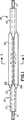
第1図は、本発明により構成されたバルーンカテーテルの一部を示す前方の平面図である。
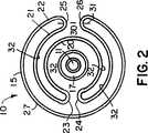
第2図は、第1図の2−2線に沿う断面図である。
第3図は、膨張状態すなわち拡大状態にある第1図のバルーンカテーテルの前方の平面図である。
第4図は、第3図の4−4線に沿う断面図である。
第5図は、第4図の5−5線に沿う拡大断面図である。
第6図は、第4図の6−6線に沿う拡大断面図である。
第7図は、第6図に示す構造の別の実施例を示す図面である。
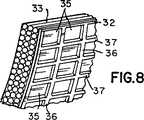
第8図は、第6図に示す構造の更に別の実施例を示す図面である。
第9図は、収縮状態すなわちコンパクト状態にあるバルーンカテーテルの前方の平面図であり、別の状態のバルーンカテーテルのへの本発明の適用を示すものである。
第10図は、第9図の10−10線に沿う断面図である。
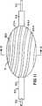
第11図は、膨張状態すなわち拡大状態にある第9図のバルーンカテーテルの前方の平面図である。
第12図は、第10図の12−12線に沿う断面図である。
発明を実施するための最良の状態
第1図〜第4図に示す実施例では、カテーテル10はガイドワイヤ11上を摺動し且つカテーテル10の遠位端14の管状部分12、13を有している。バルーン15は管状部分12、13の間で長手方向に配置されており且つ管状部分12、13に取り付けられている。第3図に仮想線で示すポート16は、バルーン15を膨張させるため、流体がバルーン15の領域内に入り得るようにする。流体は、ガイドワイヤ11を支持する管孔17(第1図)又は補助管孔(図示せず)のいずれかを通って供給されるが、これらに関する全てが従来技術において知られている。
第1図及び第2図は、薄いバルーン材料をカテーテル10の回りでコンパクト位置に配置したところを示す。明瞭化のため、第2図では、縮尺を度外視して、バルーン材料を互いに間隔を隔てて隣接する層として示しているが、実際のバルーンでは層は密に詰められている。バルーン15は、内側層20と、中間層21と、外側層22とからなる3つの同心層として形成される。中間層21は、両折曲げ部23、24がバルーン15の裏側で周方向に隣接するようにして内側層20上で折り返されている。中間層21及び外側層22は、第1図及び第2図に示すように、隣接する折曲げ部25、26を形成する。
本発明によれば、軸線30、31と折曲げ部25、26とのそれぞれの交差部によりマークされた点と点との間の外側層22の第1外面27は、患部を横切ってバルーン15を容易に移動できるようにする第1滑り摩擦係数をもつように処理される。第2外面32すなわち残りの外面は、より大きな滑り摩擦係数を有している。第2外面32の表面積は第1外面27の表面積より大きいことは明らかである。
バルーン15が第3図及び第4図に示す形状に膨張すると、外面27、32が全て露出される。しかしながら、大きな摩擦係数及び大きな表面積をもつ第2外面32が優位を占めるので、膨張バルーン15全体の摩擦係数が増大する。従って、膨張状態におけるバルーン15全体の摩擦係数は、収縮状態すなわちコンパクト状態における摩擦係数より大きい。このため、バルーン15は、そのコンパクト状態と拡大状態とで異なる摩擦係数を呈する。外面27がその摩擦係数を低下させるように処理されるならば、バルーン15は、そのコンパクト状態において低い滑り摩擦係数を有し、患部への配置を容易にする。バルーン15が拡大すると外面32が露出されるので全体の摩擦係数が増大し、このためバルーン15は、膨張中及び膨張後にその位置を保持する。
異なる摩擦係数をもつ表面を作るのに幾つかの方法及び構造がある。例えば第5図及び第6図は、第4図のバルーンカテーテルのそれぞれ第1外面27及び第2外面32に相当する部分を開示し、バルーンカテーテル15はセル状又は管状のハニカムコア33を有している。1つの方法によれば、製造中、バルーン15は第3図及び第4図に示す状態に拡大され且つ外面27、32と同延の部分に異種コーティングがコーティングされる。第1外面27には滑性(lubricousness)を最適化する材料がコーティングされ、一方、第2外面32にはより高い摩擦係数をもつ材料がコーティングされる。コーティングの硬化後、バルーンは第1図及び第2図に示す形状に収縮され且つ折り畳まれる。第1外面27のコーティングとして、ヒドロゲル、シリコーン及び親水性オイル材料からなるものがある。第2外面32はコーティングしないでおくか、ポリウレタンコーティングのような粘着性コーティングで形成するか、第1外面27と同じ材料でコーティングし、コーティング後に粗面化することもできる。
第7図はバルーン15の他の実施例を示し、この実施例では、軸線方向に間隔を隔てて周方向に延びるリブ34を第2外面32に形成することにより第2外面32に粗面化している。リブ34は、バルーン15が拡大すると周囲の組織内に穏やかに押し込まれて、周囲の組織と係合する。これにより、滑らかな第1外面27の摩擦係数より大きい、全体の摩擦係数が効果的に得られる。
第8図は、第2外面32が、周方向に延びるリブ36及び長手方向に延びるリブ37によりにより形成された成形ポケット35の配列で処理されている他の実施例を示す。バルーンが拡大すると、この網目状表面が隣接組織に穏やかに接触し且つバルーン15を所定位置に係止する。第7図又は第8図のいずれの実施例でも、表面32、27を形成する材料は同じ材料にすることができる。第7図のリブ34及び第8図のリブ36、37は、第2外面32のみと同延に設けられる。1つの製造方法によれば、ヒドロゲル材料のような滑り易いコーティングをバルーンの全表面に付着し、次に、レーザエッチングのようなエッチングによりコーティングの中間部分を除去することによりリブ34又はリブ36、37を形成することもできる。
第9図〜第12図は、ガイドワイヤ52上で遠位端まで延びた拡大可能なバルーン51を備えたバルーンカテーテル組立体50を示す。カテーテル50の互いに間隔を隔てた管状部分53、54はバルーン51を支持している。このカテーテルは、第1図〜第4図に関連して示したカテーテルとほぼ同じである。
しかしながら、この実施例では、バルーン51は、ひだを付けることによりコンパクト化される。より詳しくは、バルーン51が収縮すると、該バルーン51には、管状部分53、54と中央に配置されたマーカ57とを相互連結する中央チューブ56を中心にして、ひだ、この実施例では8つのひだ、が形成される。第9図〜第10図に示すひだ60〜67は、ベースフィルム68と複数のコーティングとからなる積層構造を有している。より詳しくは、ひだ60は、コンパクト化されたバルーン51の外面にあり且つバルーン51と長手方向に同延の中央コーティング60Aを有している。同様に、ひだ61〜67も、対応する中央の外部に露出された長手方向セクション61A〜67Aを有している。これらの表面セクション60A〜67Aは低摩擦係数を有している。これらは、バルーン51がコンパクト状態をなしているときに露出される本質的に小さな表面セクションである。
バルーン51が第11図及び第12図に示すように中央チューブ56の回りで拡大すると、ひだ60〜67は、バルーン51が拡大する組織の形状に基づいて定まる略円形状に拡がる。ひだ60についてみると、この拡がりにより、中央領域60Aの両側の領域60B、60Cが露出される。同様に、それぞれ中央領域61A〜67Aの両側には、領域61B〜67B及び61C〜67Cが露出される。領域60B〜67B及び60C〜67Cの各領域は、それぞれコーティング60A〜67Aの表面より高い摩擦係数を有している。また、領域60B〜67B及び60C〜67Cの全面積は、領域60A〜67Aの全面積より大きい。
第12図において参照番号70で示す半径方向の線70が、領域61B及び領域62Cのようなこれらの領域間の境界を示す。実際には、これらの領域61B及び62Cは連続コーティングとして形成され、半径方向の線70及び他の同様な半径方向の線は、説明上の目的のため示すに過ぎない。
第7図及び第8図に関連して示し且つ説明した表面処理を表面60B〜67Bに使用して、大きな摩擦係数をもつ間隔を隔てた領域を得ることができることが明らかである。また、第9図〜第12図に示す実施例は、第1図〜第4図に示す実施例と同様に、そのコンパクト状態及び拡大状態において異なる摩擦係数をもつバルーンカテーテルを提供する。従って、第1図〜第4図の実施例と同様に、第9図〜第12図の実施例も患部に容易に配置できる。また、この実施例も、膨張中にその全体的摩擦係数が増大するので、膨張中にその位置を保持する。第9図〜第12図の実施例は、異なる摩擦係数の領域を各1つずつもつものではなく異なる摩擦係数をもつ複数の表面を有している点で、第1図〜第4図の実施例とは異なっている。
他の特定実施例では、第1図に示すような非コーティングバルーン15が、第2図に示す状態ではあるがよりコンパクトな状態に折り畳まれる。次に、例えば親水性平滑コーティングを開示する1992年2月25日付米国特許第5,091,205号に記載の慣用的な方法で、バルーン15にコーティングが付着される。バルーン15が第2図に示すようにコンパクト化されると、バルーン15の全外面27がコーティングされる。バルーン15が第3図に示す形状に拡大されたとき、コーティングは表面27にのみ存在する。表面32はコーティングされておらず、より大きな摩擦表面を形成する。
特別に説明した上記各実施例及び他の明白な変更例では、コンパクト状態すなわち収縮状態にあるバルーンカテーテルは、患部に及び患部を横切ってバルーンを移動させる間、低い摩擦係数をもつバルーン状態を形成する。バルーンが拡大すると、高い摩擦係数をもつ表面を備えた少なくとも1つのセクションが得られ、この高い摩擦係数の表面は、バルーンが収縮しているときに露出される表面より面積が大きいため、バルーンの全体の摩擦係数を支配し且つ増大させる。これにより、バルーンを患部に安定化させ且つその好ましくない長手方向変位を最小にする。TECHNICAL FIELD The present invention relates generally to balloon catheters, and more particularly to balloon catheter structures and manufacturing methods.
Background art Coronary balloon angioplasty involves the insertion of a deflated balloon into the coronary artery and advancement of the balloon across the affected area until the center of the balloon coincides with the affected area, and then the balloon Expanding and removing the stenosis. Great efforts have been made to construct a balloon with a small cross section so that the balloon can successfully traverse a cramped affected area. However, experience with these small balloon catheters highlights two favorable, but the opposite, characteristics to date. The first property is that the balloon should have a very low coefficient of sliding friction so that initial positioning can be easily performed with minimal trauma to the tissue. The second property is that the balloon should have longitudinal or axial stability during and after its inflation. This stability is necessary to overcome any tendency that the force received from the tissue adjacent to the balloon tends to longitudinally displace (ie, move) the balloon within the vessel. Unrelated efforts have been made to deal with sliding friction and positional stability issues. However, there appears to be no activity on the development of a balloon that introduces both properties in a single device.
For example, Boston Scientific Corporation, the assignee of the present invention, is the manufacturer of a Slider ™ PTCA catheter with a lubricous, bonded coating covering the outer surface of the balloon. This catheter facilitates access to the affected area and increases the stability of the balloon across the affected area.
Similarly, the following patents disclose other coatings suitable for use with balloon catheters.
US Pat. No. 4,810,543 (1989) Gould et al. US Pat. No. 5,026,607 (1991) Kiezulas
U.S. Pat. No. 5,102,402 (1992) Dror et al. Gould et al. And Kiezulus, et al. Disclose methods and procedures for making smoother devices. However, no method or procedure for increasing axial stability is disclosed.
The following patents disclose a balloon incorporating a stabilizing structure to enhance the positioning, engagement and retention of the balloon at the affected area.
US Pat. No. 4,447,227 (1984) Kotsanis
US Pat. No. 4,896,669 (1990) Bhate et al. US Pat. No. 4,921,484 (1990) Hillstead
US Pat. No. 4,927,412 (1990) Menasche
US Pat. No. 4,986,830 (1991) Owens et al. US Pat. No. 5,002,531 (1991) Bonzel
Each of the above references proposes several structures that enhance axial stability during balloon inflation. Although Bonzel's patent recognizes the need to allow the balloon to easily pass through the affected area, none of these references disclose methods and procedures that make the balloon more slidable. Thus, although the prior art disclosed by these references has a feature that either provides low friction when the balloon is deflated or high friction when the balloon is inflated, It does not have the features of both providing a small friction when the balloon is deflated and a large friction when the balloon is inflated.
DISCLOSURE OF THE INVENTION Accordingly, it is an object of the present invention to provide an improved balloon that can be easily placed in an affected area and held in the affected area during inflation.
It is another object of the present invention to provide an improved balloon catheter that exhibits different friction characteristics in the inflated and deflated states.
Another object of the present invention is to provide a balloon catheter having a low coefficient of sliding friction in the deflated state and a high coefficient of sliding friction in the inflated state.
In accordance with the present invention, the inflatable balloon has first and second outer surface regions having different coefficients of friction. When the balloon is in a compact state, the surface regions with a high coefficient of friction are folded together so that the exposed surface region is formed by the region with a low coefficient of friction. When inflated, both surface portions engage the surrounding tissue.
[Brief description of the drawings]
FIG. 1 is a front plan view showing a part of a balloon catheter constructed according to the present invention.
FIG. 2 is a cross-sectional view taken along line 2-2 of FIG.
FIG. 3 is a plan view of the front of the balloon catheter of FIG. 1 in an inflated or expanded state.
FIG. 4 is a sectional view taken along line 4-4 of FIG.
FIG. 5 is an enlarged cross-sectional view taken along line 5-5 of FIG.
FIG. 6 is an enlarged sectional view taken along line 6-6 of FIG.
FIG. 7 is a drawing showing another embodiment of the structure shown in FIG.
FIG. 8 is a drawing showing still another embodiment of the structure shown in FIG.
FIG. 9 is a plan view of the front of the balloon catheter in the deflated state, that is, the compact state, and shows the application of the present invention to the balloon catheter in another state.
FIG. 10 is a sectional view taken along line 10-10 of FIG.
FIG. 11 is a plan view of the front side of the balloon catheter of FIG. 9 in an inflated or expanded state.
FIG. 12 is a sectional view taken along line 12-12 of FIG.
BESTMODE FORCARRYING OUT THE INVENTION In the embodiment shown in FIGS. 1-4, the
FIGS. 1 and 2 show a thin balloon material placed around the
According to the present invention, the first
When the
There are several methods and structures for creating surfaces with different coefficients of friction. For example, FIGS. 5 and 6 disclose portions corresponding to the first
FIG. 7 shows another embodiment of the
FIG. 8 shows another embodiment in which the second
FIGS. 9-12 show a
However, in this embodiment, the
When the
A
It is clear that the surface treatments shown and described in connection with FIGS. 7 and 8 can be used on the
In another particular embodiment, an
In each of the above-described embodiments and other obvious modifications specifically described, a balloon catheter in a compact or deflated state creates a balloon condition with a low coefficient of friction while moving the balloon into and across the affected area. To do. When the balloon is expanded, at least one section with a surface with a high coefficient of friction is obtained, which surface has a larger area than the surface exposed when the balloon is deflated. Dominate and increase the overall coefficient of friction. This stabilizes the balloon at the affected area and minimizes its undesirable longitudinal displacement.
Claims (3)
Translated fromJapanese上記バルーンは、内面及び外面を有し、この外面は、上記軸線方向に延びる第1外表面部分及び第2外表面部分を有し、上記第1外表面部分は、上記バルーンのコンパクト形状及び膨張形状において露出され、上記第2外表面部分は、上記バルーンのコンパクト形状において露出しないで膨張形状において露出され、上記第1外表面部分及び上記第2外表面部分は、互いに異なる摺動摩擦特性を有し、上記第1外表面部分の摺動摩擦特性は、コンパクト形状の上記バルーンが患者の血管と係合するときの上記バルーンの摺動摩擦特性全体を支配し、上記第2外表面部分の摺動摩擦特性は、膨張形状に膨張した後の上記バルーンと患者の血管との間の上記バルーンの摺動摩擦特性全体を実質的に支配し、
上記第2外表面部分に、間隔を隔てたリブが設けられ、それにより、上記第1外表面部分よりも摺動摩擦特性が大きいリブ付き外面部分が形成されることを特徴とするバルーンカテーテル。A catheter including a lumen and a balloon mounted on the catheter, wherein the balloon is in communication with the lumen to selectively inflate it from a compact shape to an inflated shape about the catheter axis. A balloon catheter for insertion into a patient's blood vessel,
The balloon has an inner surface and an outer surface, and the outer surface has a first outer surface portion and a second outer surface portion extending in the axial direction, and the first outer surface portion has a compact shape and an inflation of the balloon. Exposed in shape, the second outer surface portion is exposed in an inflated shape without being exposed in the compact shape of the balloon, and the first outer surface portion and the second outer surface portion have different sliding friction characteristics. The sliding friction characteristic of the first outer surface part dominates the entire sliding friction characteristic of the balloon when the compact balloon is engaged with the blood vessel of the patient, and the sliding friction characteristic of the second outer surface part. Substantially governs the overall sliding friction properties of the balloon between the balloon and the patient's blood vessel after inflating into an inflated shape;
A balloon catheter characterized inthat ribs are provided at intervals on the second outer surface portion, thereby forming an outer surface portion with ribs having a sliding friction characteristic larger than that of the first outer surface portion .
Applications Claiming Priority (3)
| Application Number | Priority Date | Filing Date | Title |
|---|---|---|---|
| US11065593A | 1993-08-23 | 1993-08-23 | |
| US08/110,655 | 1993-08-23 | ||
| PCT/US1994/009489WO1995005860A1 (en) | 1993-08-23 | 1994-08-23 | Improved balloon catheter |
Related Child Applications (1)
| Application Number | Title | Priority Date | Filing Date |
|---|---|---|---|
| JP2005137585ADivisionJP3836861B2 (en) | 1993-08-23 | 2005-05-10 | Balloon catheter |
Publications (2)
| Publication Number | Publication Date |
|---|---|
| JPH09501598A JPH09501598A (en) | 1997-02-18 |
| JP3694524B2true JP3694524B2 (en) | 2005-09-14 |
Family
ID=22334180
Family Applications (2)
| Application Number | Title | Priority Date | Filing Date |
|---|---|---|---|
| JP50771995AExpired - LifetimeJP3694524B2 (en) | 1993-08-23 | 1994-08-23 | Improved balloon catheter |
| JP2005137585AExpired - LifetimeJP3836861B2 (en) | 1993-08-23 | 2005-05-10 | Balloon catheter |
Family Applications After (1)
| Application Number | Title | Priority Date | Filing Date |
|---|---|---|---|
| JP2005137585AExpired - LifetimeJP3836861B2 (en) | 1993-08-23 | 2005-05-10 | Balloon catheter |
Country Status (5)
| Country | Link |
|---|---|
| US (1) | US5693014A (en) |
| EP (1) | EP0746362B1 (en) |
| JP (2) | JP3694524B2 (en) |
| DE (1) | DE69429670T2 (en) |
| WO (1) | WO1995005860A1 (en) |
Families Citing this family (153)
| Publication number | Priority date | Publication date | Assignee | Title |
|---|---|---|---|---|
| US5879499A (en)* | 1996-06-17 | 1999-03-09 | Heartport, Inc. | Method of manufacture of a multi-lumen catheter |
| US5795325A (en) | 1991-07-16 | 1998-08-18 | Heartport, Inc. | Methods and apparatus for anchoring an occluding member |
| US5746745A (en)* | 1993-08-23 | 1998-05-05 | Boston Scientific Corporation | Balloon catheter |
| US5836965A (en) | 1994-10-19 | 1998-11-17 | Jendersee; Brad | Stent delivery and deployment method |
| US6306144B1 (en)* | 1996-11-01 | 2001-10-23 | Scimed Life Systems, Inc. | Selective coating of a balloon catheter with lubricious material for stent deployment |
| US5863366A (en)* | 1995-06-07 | 1999-01-26 | Heartport, Inc. | Method of manufacture of a cannula for a medical device |
| US6302875B1 (en)* | 1996-10-11 | 2001-10-16 | Transvascular, Inc. | Catheters and related devices for forming passageways between blood vessels or other anatomical structures |
| US5733301A (en)* | 1996-01-11 | 1998-03-31 | Schneider (Usa) Inc. | Laser ablation of angioplasty catheters and balloons |
| US5954713A (en) | 1996-07-12 | 1999-09-21 | Newman; Fredric A. | Endarterectomy surgical instruments and procedure |
| US5954740A (en)* | 1996-09-23 | 1999-09-21 | Boston Scientific Corporation | Catheter balloon having raised radial segments |
| US6013055A (en)* | 1997-11-13 | 2000-01-11 | Boston Scientific Corporation | Catheter balloon having selected folding characteristics |
| US6589213B2 (en)* | 1997-12-12 | 2003-07-08 | Wilson-Cook Medical Incorporated | Body canal intrusion instrumentation having bi-directional coefficient of surface friction with body tissue |
| US20030097138A1 (en)* | 1997-12-12 | 2003-05-22 | Boris Reydel | Body canal intrusion instrumentation having bi-directional coefficient of surface friction with body tissue |
| US6767339B2 (en) | 1997-12-12 | 2004-07-27 | Wilson-Cook Medical, Inc. | Body canal intrusion instrumentation having bidirectional coefficient of surface friction with body tissue |
| JP3540745B2 (en)* | 1998-03-09 | 2004-07-07 | ドクトア・フレッド・ゲーベル・パテントフェアバルトゥング・ゲー・エム・ベー・ハー | Tracheal ventilation device |
| US8177743B2 (en) | 1998-05-18 | 2012-05-15 | Boston Scientific Scimed, Inc. | Localized delivery of drug agents |
| US6280411B1 (en)* | 1998-05-18 | 2001-08-28 | Scimed Life Systems, Inc. | Localized delivery of drug agents |
| US6206283B1 (en)* | 1998-12-23 | 2001-03-27 | At&T Corp. | Method and apparatus for transferring money via a telephone call |
| US6613066B1 (en)* | 1998-10-05 | 2003-09-02 | Kaneka Corporation | Balloon catheter and production method therefor |
| US6129706A (en)* | 1998-12-10 | 2000-10-10 | Janacek; Jaroslav | Corrugated catheter balloon |
| US6955661B1 (en) | 1999-01-25 | 2005-10-18 | Atrium Medical Corporation | Expandable fluoropolymer device for delivery of therapeutic agents and method of making |
| US6443980B1 (en) | 1999-03-22 | 2002-09-03 | Scimed Life Systems, Inc. | End sleeve coating for stent delivery |
| US6786889B1 (en) | 1999-03-31 | 2004-09-07 | Scimed Life Systems, Inc | Textured and/or marked balloon for stent delivery |
| US6258099B1 (en) | 1999-03-31 | 2001-07-10 | Scimed Life Systems, Inc. | Stent security balloon/balloon catheter |
| GB9930654D0 (en)* | 1999-12-23 | 2000-02-16 | Halpin Richard M B | Device for controlling extra-vascular haemorrhage |
| US7479128B1 (en)* | 2000-01-04 | 2009-01-20 | Boston Scientific Scimed, Inc. | Protective coatings for medical devices |
| US6471968B1 (en) | 2000-05-12 | 2002-10-29 | Regents Of The University Of Michigan | Multifunctional nanodevice platform |
| DE10115740A1 (en) | 2001-03-26 | 2002-10-02 | Ulrich Speck | Preparation for restenosis prophylaxis |
| FR2824367B1 (en)* | 2001-05-04 | 2003-07-18 | Roulements Soc Nouvelle | ASSEMBLY COMPRISING AN INSTRUMENT BEARING AND A HOUSING ASSOCIATED BY A SLEEVE PIECE |
| US7985234B2 (en)* | 2002-02-27 | 2011-07-26 | Boston Scientific Scimed, Inc. | Medical device |
| US7951164B2 (en)* | 2002-02-28 | 2011-05-31 | Boston Scientific Scimed, Inc. | Balloon folding apparatus, methods and products |
| US7758605B2 (en)* | 2002-02-28 | 2010-07-20 | Boston Scientific Scimed, Inc. | Balloon folding apparatus, methods and products |
| US7008979B2 (en) | 2002-04-30 | 2006-03-07 | Hydromer, Inc. | Coating composition for multiple hydrophilic applications |
| US20030236563A1 (en)* | 2002-06-20 | 2003-12-25 | Dan Fifer | Stent delivery catheter with retention bands |
| US7166120B2 (en)* | 2002-07-12 | 2007-01-23 | Ev3 Inc. | Catheter with occluding cuff |
| DE10244847A1 (en)* | 2002-09-20 | 2004-04-01 | Ulrich Prof. Dr. Speck | Medical device for drug delivery |
| US9849279B2 (en) | 2008-06-27 | 2017-12-26 | Medtronic, Inc. | Lead delivery device and method |
| US9480839B2 (en) | 2002-09-24 | 2016-11-01 | Medtronic, Inc. | Lead delivery device and method |
| US9636499B2 (en)* | 2002-09-24 | 2017-05-02 | Medtronic, Inc. | Lead delivery device and method |
| US8920432B2 (en)* | 2002-09-24 | 2014-12-30 | Medtronic, Inc. | Lead delivery device and method |
| US6989025B2 (en)* | 2002-10-04 | 2006-01-24 | Boston Scientific Scimed, Inc. | Extruded tubing with discontinuous striping |
| US7025752B2 (en)* | 2002-11-06 | 2006-04-11 | Advanced Cardiovascular Systems, Inc. | Reduced slippage balloon catheter and method of using same |
| US20040176790A1 (en)* | 2003-03-03 | 2004-09-09 | Medtronic Ave, Inc. | Single lumen catheter shaft for a balloon catheter |
| US20040215315A1 (en)* | 2003-04-25 | 2004-10-28 | Jones Ryan A. | Drug-eluting stent with sheath and balloon deployment assembly |
| JP2007516016A (en)* | 2003-05-22 | 2007-06-21 | リーディング メディカル リサーチ エル.エル.シー. | Tubular device for insertion into a luminal organ and method for manufacturing the same |
| US7744620B2 (en) | 2003-07-18 | 2010-06-29 | Intervalve, Inc. | Valvuloplasty catheter |
| US8021331B2 (en)* | 2003-09-15 | 2011-09-20 | Atrium Medical Corporation | Method of coating a folded medical device |
| JP4443278B2 (en)* | 2004-03-26 | 2010-03-31 | テルモ株式会社 | Catheter with expansion body |
| JP2008510829A (en)* | 2004-08-25 | 2008-04-10 | ザ リージェンツ オブ ザ ユニバーシティ オブ ミシガン | Compositions based on dendrimers and their use |
| US9801913B2 (en) | 2004-09-28 | 2017-10-31 | Atrium Medical Corporation | Barrier layer |
| US9000040B2 (en) | 2004-09-28 | 2015-04-07 | Atrium Medical Corporation | Cross-linked fatty acid-based biomaterials |
| US9012506B2 (en) | 2004-09-28 | 2015-04-21 | Atrium Medical Corporation | Cross-linked fatty acid-based biomaterials |
| US20060184191A1 (en) | 2005-02-11 | 2006-08-17 | Boston Scientific Scimed, Inc. | Cutting balloon catheter having increased flexibility regions |
| US20060182873A1 (en)* | 2005-02-17 | 2006-08-17 | Klisch Leo M | Medical devices |
| WO2006090351A1 (en)* | 2005-02-21 | 2006-08-31 | Diagles Ltd | Method and apparatus for mechanical measurement of sphincters and narrowing regions in hollow biological organs |
| US8672990B2 (en)* | 2005-05-27 | 2014-03-18 | Boston Scientific Scimed, Inc. | Fiber mesh controlled expansion balloon catheter |
| US7691082B2 (en)* | 2005-07-01 | 2010-04-06 | Boston Scientific Scimed, Inc. | Medical devices |
| US20070041934A1 (en)* | 2005-08-12 | 2007-02-22 | Regents Of The University Of Michigan | Dendrimer based compositions and methods of using the same |
| US9278161B2 (en) | 2005-09-28 | 2016-03-08 | Atrium Medical Corporation | Tissue-separating fatty acid adhesion barrier |
| US9427423B2 (en) | 2009-03-10 | 2016-08-30 | Atrium Medical Corporation | Fatty-acid based particles |
| US8876763B2 (en)* | 2005-11-01 | 2014-11-04 | Boston Scientific Scimed, Inc. | Composite balloon |
| JP2009519770A (en)* | 2005-12-16 | 2009-05-21 | インターフェイス・アソシエイツ・インコーポレーテッド | Medical multilayer balloon and method for producing the same |
| BRPI0707681A2 (en) | 2006-02-01 | 2011-05-10 | Cleveland Clinic Foudation | Method and apparatus for increasing blood flow through a blocked artery |
| US20070282306A1 (en)* | 2006-06-05 | 2007-12-06 | Twincath, Llc | Multi-lumen catheter with protected tip |
| US20070288033A1 (en)* | 2006-06-09 | 2007-12-13 | Allergan, Inc. | Intragastric balloon retrieval mechanisms |
| US8196584B2 (en) | 2006-06-22 | 2012-06-12 | Nellcor Puritan Bennett Llc | Endotracheal cuff and technique for using the same |
| US8434487B2 (en) | 2006-06-22 | 2013-05-07 | Covidien Lp | Endotracheal cuff and technique for using the same |
| US7963942B2 (en)* | 2006-09-20 | 2011-06-21 | Boston Scientific Scimed, Inc. | Medical balloons with modified surfaces |
| US8684175B2 (en) | 2006-09-22 | 2014-04-01 | Covidien Lp | Method for shipping and protecting an endotracheal tube with an inflated cuff |
| US20080078405A1 (en) | 2006-09-29 | 2008-04-03 | Crumback Gary L | Self-sizing adjustable endotracheal tube |
| US20080078399A1 (en) | 2006-09-29 | 2008-04-03 | O'neil Michael P | Self-sizing adjustable endotracheal tube |
| US7950393B2 (en) | 2006-09-29 | 2011-05-31 | Nellcor Puritan Bennett Llc | Endotracheal cuff and technique for using the same |
| US9326877B2 (en)* | 2006-09-29 | 2016-05-03 | Apollo Endosurgery, Inc. | Apparatus and method for intragastric balloon with in situ adjustment means |
| US8807136B2 (en) | 2006-09-29 | 2014-08-19 | Covidien Lp | Self-sizing adjustable endotracheal tube |
| US8307830B2 (en) | 2006-09-29 | 2012-11-13 | Nellcor Puritan Bennett Llc | Endotracheal cuff and technique for using the same |
| US8153181B2 (en)* | 2006-11-14 | 2012-04-10 | Boston Scientific Scimed, Inc. | Medical devices and related methods |
| US8052639B2 (en)* | 2007-04-10 | 2011-11-08 | Wilson David B | Clampless anastomotic device |
| US20080255601A1 (en)* | 2007-04-13 | 2008-10-16 | Allergan, Inc. | Apparatus and method for remote deflation of intragastric balloon |
| AU2008275501A1 (en)* | 2007-04-19 | 2009-01-15 | The Regents Of The University Of Michigan | Dendrimer based compositions and methods of using the same |
| EP2095795A1 (en)* | 2007-12-21 | 2009-09-02 | Abbott Laboratories Vascular Enterprises Limited | Double layered balloons in medical devices |
| US8750978B2 (en) | 2007-12-31 | 2014-06-10 | Covidien Lp | System and sensor for early detection of shock or perfusion failure and technique for using the same |
| WO2009111716A1 (en)* | 2008-03-06 | 2009-09-11 | Boston Scientific Scimed, Inc. | Balloon catheter devices with sheath covering |
| WO2009151687A2 (en) | 2008-03-12 | 2009-12-17 | The Regents Of The University Of Michigan | Dendrimer conjugates |
| US20090326643A1 (en)* | 2008-06-27 | 2009-12-31 | Boston Scientific Scimed, Inc. | Balloon folding apparatus and method |
| US9775990B2 (en) | 2008-06-27 | 2017-10-03 | Medtronic, Inc. | Lead delivery device and method |
| US11931523B2 (en) | 2008-06-27 | 2024-03-19 | Medtronic, Inc. | Lead delivery device and method |
| US9775989B2 (en) | 2008-06-27 | 2017-10-03 | Medtronic, Inc. | Lead delivery device and method |
| US9067045B2 (en) | 2008-07-25 | 2015-06-30 | Cook Medical Technologies Llc | Balloon catheter and method for making same |
| EP2344236B1 (en)* | 2008-07-31 | 2015-06-17 | Medtronic, Inc. | Implantable lead delivery device |
| WO2010039861A2 (en) | 2008-09-30 | 2010-04-08 | The Regents Of The University Of Michigan | Dendrimer conjugates |
| US7951111B2 (en) | 2008-10-10 | 2011-05-31 | Intervalve, Inc. | Valvuloplasty catheter and methods |
| US9017644B2 (en) | 2008-11-07 | 2015-04-28 | The Regents Of The University Of Michigan | Methods of treating autoimmune disorders and/or inflammatory disorders |
| US8381730B2 (en)* | 2009-01-29 | 2013-02-26 | Covidien Lp | Medical device and technique for using the same |
| EP2431066B1 (en) | 2009-05-14 | 2014-02-12 | Terumo Kabushiki Kaisha | Method of manufacturing balloon catheter and balloon catheter |
| US8590534B2 (en) | 2009-06-22 | 2013-11-26 | Covidien Lp | Cuff for use with medical tubing and method and apparatus for making the same |
| US20110038910A1 (en) | 2009-08-11 | 2011-02-17 | Atrium Medical Corporation | Anti-infective antimicrobial-containing biomaterials |
| EP2470232B1 (en)* | 2009-08-27 | 2016-03-30 | Boston Scientific Scimed, Inc. | Balloon catheter devices with drug-coated sheath |
| EP2488172A4 (en) | 2009-10-13 | 2014-08-13 | Univ Michigan | DENDRIMER COMPOSITIONS AND METHODS OF SYNTHESIS |
| US8636724B2 (en)* | 2009-10-26 | 2014-01-28 | Poiesis Medical, Llc | Balloon encapsulated catheter tip |
| US8912323B2 (en) | 2009-10-30 | 2014-12-16 | The Regents Of The University Of Michigan | Multifunctional small molecules |
| US9339291B2 (en)* | 2009-12-29 | 2016-05-17 | Cook Medical Technologies Llc | Cutting or scoring balloon, system and method of making a cutting or scoring balloon |
| US20110178503A1 (en)* | 2010-01-21 | 2011-07-21 | Boston Scientific Scimed, Inc. | Balloon catheters with therapeutic agent in balloon folds and methods of making the same |
| CN105193371B (en) | 2010-03-09 | 2020-11-24 | 智能医疗系统有限公司 | Balloon endoscope and methods of making and using the same |
| US20110270025A1 (en) | 2010-04-30 | 2011-11-03 | Allergan, Inc. | Remotely powered remotely adjustable gastric band system |
| WO2012009707A2 (en) | 2010-07-16 | 2012-01-19 | Atrium Medical Corporation | Composition and methods for altering the rate of hydrolysis of cured oil-based materials |
| US9242081B2 (en) | 2010-09-13 | 2016-01-26 | Intervalve, Inc. | Positionable valvuloplasty catheter |
| ES2565348T3 (en) | 2010-10-18 | 2016-04-04 | Apollo Endosurgery, Inc. | Intragastric implant reagent devices |
| US9463107B2 (en) | 2010-10-18 | 2016-10-11 | Apollo Endosurgery, Inc. | Variable size intragastric implant devices |
| US20130116549A1 (en)* | 2010-10-18 | 2013-05-09 | Erhan H. Gunday | Anchored Working Channel |
| ES2566498T3 (en) | 2010-10-18 | 2016-04-13 | Apollo Endosurgery, Inc. | Intragastric implants with duodenal anchors |
| US8870966B2 (en) | 2010-10-18 | 2014-10-28 | Apollo Endosurgery, Inc. | Intragastric balloon for treating obesity |
| US20120095292A1 (en) | 2010-10-18 | 2012-04-19 | Gunday Erhan H | Anchored Guidewire |
| US8864840B2 (en) | 2010-10-19 | 2014-10-21 | Apollo Endosurgery, Inc. | Intragastric implants with collapsible frames |
| US9198790B2 (en) | 2010-10-19 | 2015-12-01 | Apollo Endosurgery, Inc. | Upper stomach gastric implants |
| US8920447B2 (en) | 2010-10-19 | 2014-12-30 | Apollo Endosurgery, Inc. | Articulated gastric implant clip |
| US9398969B2 (en) | 2010-10-19 | 2016-07-26 | Apollo Endosurgery, Inc. | Upper stomach gastric implants |
| WO2012054522A2 (en) | 2010-10-19 | 2012-04-26 | Allergan, Inc. | Anchored non-piercing duodenal sleeve and delivery systems |
| US9498365B2 (en) | 2010-10-19 | 2016-11-22 | Apollo Endosurgery, Inc. | Intragastric implants with multiple fluid chambers |
| EP3998099A1 (en) | 2011-03-07 | 2022-05-18 | Smart Medical Systems Ltd. | Balloon-equipped endoscopic devices and methods thereof |
| US8888732B2 (en) | 2011-03-11 | 2014-11-18 | Apollo Endosurgery, Inc. | Intraluminal sleeve with active agents |
| US8795228B2 (en) | 2011-05-05 | 2014-08-05 | Boston Scientific Scimed, Inc. | Drug delivery device with sheath for improved drug delivery |
| US9186129B2 (en)* | 2011-05-26 | 2015-11-17 | Adn International, Llc | Expandable device for tissue collection from an aerodigestive body lumen |
| WO2012170501A1 (en) | 2011-06-07 | 2012-12-13 | Boston Scientific Scimed, Inc. | Drug delivery device with instable sheath and/or push element |
| US8574221B2 (en) | 2011-09-09 | 2013-11-05 | Cook Medical Technologies Llc | Tubular medical device |
| US9730726B2 (en) | 2011-10-07 | 2017-08-15 | W. L. Gore & Associates, Inc. | Balloon assemblies having controllably variable topographies |
| US9861444B2 (en) | 2011-11-01 | 2018-01-09 | The Johns Hopkins University | Method and device for endoscopic abrasion |
| CA2857006A1 (en)* | 2011-12-02 | 2013-06-06 | Sil Vascular Ltd. | Balloon catheter system |
| WO2013085718A1 (en) | 2011-12-08 | 2013-06-13 | The Regents Of The University Of Michigan | Multifunctional small molecules |
| JP5912685B2 (en)* | 2012-03-08 | 2016-04-27 | 株式会社東海メディカルプロダクツ | Balloon for IABP balloon catheter |
| US9283100B2 (en) | 2012-05-16 | 2016-03-15 | Abbott Cardiovascular Systems Inc. | Polymer scaffold with multi-pleated balloon |
| US9867880B2 (en) | 2012-06-13 | 2018-01-16 | Atrium Medical Corporation | Cured oil-hydrogel biomaterial compositions for controlled drug delivery |
| US9901715B2 (en)* | 2012-09-05 | 2018-02-27 | W. L. Gore Associates, Inc. | Retractable sheath devices, systems, and methods |
| US10758667B2 (en)* | 2013-02-04 | 2020-09-01 | Michael Rontal | Balloon irrigation and cleaning system for interior walls of body cavities |
| US9669194B2 (en) | 2013-03-14 | 2017-06-06 | W. L. Gore & Associates, Inc. | Conformable balloon devices and methods |
| CN114951190A (en) | 2013-05-21 | 2022-08-30 | 智能医疗系统有限公司 | Endoscope reprocessing system and method |
| JP6332922B2 (en)* | 2013-07-31 | 2018-05-30 | フクダ電子株式会社 | Balloon catheter and balloon manufacturing method used for balloon catheter |
| WO2015104589A1 (en) | 2014-01-13 | 2015-07-16 | Shanghai Lawring Biomedical Co., Ltd | Dendrimer compositions, methods of synthesis, and uses thereof |
| US20150250988A1 (en)* | 2014-03-07 | 2015-09-10 | Translational Biologic Infusion Catheter, Llc | Prolate Spheroid-Shaped Balloon |
| US10159486B2 (en) | 2014-05-21 | 2018-12-25 | The Regents Of The University Of Michigan | Fenestrated decoupling system for internal selective attachment to soft tissue organs |
| AU2015369539B2 (en) | 2014-12-22 | 2020-06-25 | Smart Medical Systems Ltd. | Balloon endoscope reprocessing system and method |
| GB201511595D0 (en)* | 2014-12-23 | 2015-08-19 | Whiteley Mark | Medical device for treating a vein |
| US10117738B2 (en) | 2015-01-23 | 2018-11-06 | The Regents Of The University Of Michigan | Atraumatic tip geometry for indwelling devices |
| CA2979712C (en) | 2015-03-25 | 2024-01-23 | The Regents Of The University Of Michigan | Nanoparticle compositions for delivery of biomacromolecules |
| US10835107B2 (en) | 2015-04-03 | 2020-11-17 | Smart Medical Systems Ltd. | Endoscope electro-pneumatic adaptor |
| JP7495778B2 (en) | 2015-10-07 | 2024-06-05 | メイヨ・ファウンデーション・フォー・メディカル・エデュケーション・アンド・リサーチ | Electroporation for the treatment of obesity or diabetes |
| CA3017813C (en) | 2016-03-17 | 2021-12-07 | Oslo Universitetssykehus Hf | Fusion proteins targeting tumour associated macrophages for treating cancer |
| WO2018038836A1 (en)* | 2016-08-26 | 2018-03-01 | Translational Biologic Infusion Catheter, Llc | Prolate spheroid-shaped balloon with central hinge |
| JP6319777B1 (en)* | 2016-09-05 | 2018-05-09 | 朝日インテック株式会社 | Guide wire |
| CN108601927A (en)* | 2016-11-22 | 2018-09-28 | 朝日英达科株式会社 | Balloon catheter |
| US20190358263A1 (en) | 2016-12-07 | 2019-11-28 | Oslo Universitetssykehus Hf | Compositions and Methods for Cell Therapy |
| EP3585305B1 (en)* | 2017-02-23 | 2025-07-30 | Boston Scientific Scimed, Inc. | Medical drain device |
| WO2019195641A2 (en) | 2018-04-06 | 2019-10-10 | The Regents Of The University Of Michigan | Inhibitors of rho/mrtf/srf-mediated gene transcription and methods for use of the same |
| CN113116618A (en)* | 2019-12-31 | 2021-07-16 | 上海鸿脉医疗科技有限公司 | Implant delivery system and inner tube thereof |
Family Cites Families (35)
| Publication number | Priority date | Publication date | Assignee | Title |
|---|---|---|---|---|
| US2330400A (en)* | 1937-09-11 | 1943-09-28 | American Anode Inc | Method of making distensible bag catheters and the like |
| US2701559A (en)* | 1951-08-02 | 1955-02-08 | William A Cooper | Apparatus for exfoliating and collecting diagnostic material from inner walls of hollow viscera |
| US2927584A (en)* | 1958-04-16 | 1960-03-08 | American Cystoscope Makers Inc | Means for anchoring a surgical device and a surgical drain embodying the same |
| GB892980A (en)* | 1958-07-31 | 1962-04-04 | Us Catheter & Instr Corp | Blood vessel prosthesis and process of making same |
| US3967728A (en)* | 1973-03-02 | 1976-07-06 | International Paper Company | Catheter package |
| US4447227A (en)* | 1982-06-09 | 1984-05-08 | Endoscopy Surgical Systems, Inc. | Multi-purpose medical devices |
| US4465072A (en)* | 1983-02-22 | 1984-08-14 | Taheri Syde A | Needle catheter |
| US4572186A (en)* | 1983-12-07 | 1986-02-25 | Cordis Corporation | Vessel dilation |
| US4629459A (en)* | 1983-12-28 | 1986-12-16 | Shiley Inc. | Alternate stent covering for tissue valves |
| US4555242A (en)* | 1984-01-19 | 1985-11-26 | Saudagar Abdul S | Urinary drainage appliance |
| US4917088A (en)* | 1985-05-02 | 1990-04-17 | C. R. Bard, Inc. | Balloon dilation probe |
| DE3519626A1 (en)* | 1985-05-31 | 1986-12-04 | Stöckert Instrumente GmbH, 8000 München | BALLOON CATHETER |
| US4878906A (en)* | 1986-03-25 | 1989-11-07 | Servetus Partnership | Endoprosthesis for repairing a damaged vessel |
| DE3621350A1 (en)* | 1986-06-26 | 1988-01-14 | Bonzel Tassilo | DILATATION CATHETER WITH AN EXPANDABLE BALLOON |
| US4810543A (en)* | 1986-10-17 | 1989-03-07 | Tyndale Plains-Hunter Ltd. | Articles having low friction surfaces and production thereof |
| US4796629A (en)* | 1987-06-03 | 1989-01-10 | Joseph Grayzel | Stiffened dilation balloon catheter device |
| JPS6446477A (en)* | 1987-08-13 | 1989-02-20 | Terumo Corp | Catheter |
| DE3821544C2 (en)* | 1988-06-25 | 1994-04-28 | H Prof Dr Med Just | Dilatation catheter |
| US4921484A (en)* | 1988-07-25 | 1990-05-01 | Cordis Corporation | Mesh balloon catheter device |
| US4896669A (en)* | 1988-08-31 | 1990-01-30 | Meadox Medicals, Inc. | Dilatation catheter |
| US5092877A (en)* | 1988-09-01 | 1992-03-03 | Corvita Corporation | Radially expandable endoprosthesis |
| US4950227A (en)* | 1988-11-07 | 1990-08-21 | Boston Scientific Corporation | Stent delivery system |
| US5019042A (en)* | 1988-11-23 | 1991-05-28 | Harvinder Sahota | Balloon catheters |
| US4927412A (en)* | 1988-12-08 | 1990-05-22 | Retroperfusion Systems, Inc. | Coronary sinus catheter |
| US5091205A (en)* | 1989-01-17 | 1992-02-25 | Union Carbide Chemicals & Plastics Technology Corporation | Hydrophilic lubricious coatings |
| US5092348A (en)* | 1989-01-17 | 1992-03-03 | Mcghan Medical Corporation | Textured tissue expander |
| US4941877A (en)* | 1989-01-26 | 1990-07-17 | Cordis Corporation | Balloon catheter |
| US5049131A (en)* | 1989-05-31 | 1991-09-17 | Ashridge Ag | Balloon catheter |
| US5026607A (en)* | 1989-06-23 | 1991-06-25 | C. R. Bard, Inc. | Medical apparatus having protective, lubricious coating |
| US4955859A (en)* | 1989-07-07 | 1990-09-11 | C. R. Bard, Inc. | High-friction prostatic stent |
| DE9010130U1 (en)* | 1989-07-13 | 1990-09-13 | American Medical Systems, Inc., Minnetonka, Minn. | Instrument for attaching an expansion implant |
| US4986830A (en)* | 1989-09-22 | 1991-01-22 | Schneider (U.S.A.) Inc. | Valvuloplasty catheter with balloon which remains stable during inflation |
| US5320634A (en)* | 1990-07-03 | 1994-06-14 | Interventional Technologies, Inc. | Balloon catheter with seated cutting edges |
| US5102402A (en)* | 1991-01-04 | 1992-04-07 | Medtronic, Inc. | Releasable coatings on balloon catheters |
| US5250070A (en)* | 1991-05-28 | 1993-10-05 | Parodi Juan C | Less traumatic angioplasty balloon for arterial dilatation |
- 1994
- 1994-08-23JPJP50771995Apatent/JP3694524B2/ennot_activeExpired - Lifetime
- 1994-08-23EPEP94926561Apatent/EP0746362B1/ennot_activeExpired - Lifetime
- 1994-08-23DEDE69429670Tpatent/DE69429670T2/ennot_activeExpired - Lifetime
- 1994-08-23WOPCT/US1994/009489patent/WO1995005860A1/enactiveIP Right Grant
- 1995
- 1995-05-15USUS08/441,603patent/US5693014A/ennot_activeExpired - Lifetime
- 2005
- 2005-05-10JPJP2005137585Apatent/JP3836861B2/ennot_activeExpired - Lifetime
Also Published As
| Publication number | Publication date |
|---|---|
| JPH09501598A (en) | 1997-02-18 |
| WO1995005860A1 (en) | 1995-03-02 |
| DE69429670D1 (en) | 2002-02-21 |
| JP2005224635A (en) | 2005-08-25 |
| US5693014A (en) | 1997-12-02 |
| EP0746362B1 (en) | 2002-01-16 |
| EP0746362A4 (en) | 1998-01-14 |
| DE69429670T2 (en) | 2002-08-22 |
| JP3836861B2 (en) | 2006-10-25 |
| EP0746362A1 (en) | 1996-12-11 |
Similar Documents
| Publication | Publication Date | Title |
|---|---|---|
| JP3694524B2 (en) | Improved balloon catheter | |
| JP3753437B2 (en) | Balloon catheter | |
| US5344426A (en) | Method and system for stent delivery | |
| US5573508A (en) | Catheter with an expandable perfusion lumen | |
| US5242399A (en) | Method and system for stent delivery | |
| US5458605A (en) | Coiled reinforced retractable sleeve for stent delivery catheter | |
| US5573509A (en) | Catheter with an expandable perfusion slit | |
| US5628754A (en) | Stent delivery guide catheter | |
| US7172587B2 (en) | Catheter having selectively varied lamination | |
| JPH07505795A (en) | Dilation catheter with polyimide wrapped stainless steel braided proximal shaft | |
| WO1994005365A1 (en) | Perfusion dilatation catheter | |
| WO2018096572A1 (en) | Balloon catheter | |
| JPH0357464A (en) | Catheter | |
| EP2621579B1 (en) | Method of forming a balloon with integrally retained dilation element | |
| JP4850707B2 (en) | Balloon assembly with torque | |
| JP4829456B2 (en) | Stent delivery balloon having stent fixing means | |
| US5700242A (en) | Balloon catheter and method for facilitating increased radial expansion | |
| EP1753497B1 (en) | Folded balloon for catheter | |
| JP2005524418A (en) | Eccentric catheter shaft | |
| CA2170157C (en) | Improved balloon catheter | |
| JP3142351B2 (en) | Balloon outer diameter adjusting device for dilatation catheter, and dilatation catheter having the same | |
| JP4435903B2 (en) | Medical balloon catheter | |
| JPH02224668A (en) | Balloon catheter for expansion |
Legal Events
| Date | Code | Title | Description |
|---|---|---|---|
| A131 | Notification of reasons for refusal | Free format text:JAPANESE INTERMEDIATE CODE: A131 Effective date:20040511 | |
| A601 | Written request for extension of time | Free format text:JAPANESE INTERMEDIATE CODE: A601 Effective date:20040811 | |
| A602 | Written permission of extension of time | Free format text:JAPANESE INTERMEDIATE CODE: A602 Effective date:20040927 | |
| A521 | Request for written amendment filed | Free format text:JAPANESE INTERMEDIATE CODE: A523 Effective date:20041110 | |
| A02 | Decision of refusal | Free format text:JAPANESE INTERMEDIATE CODE: A02 Effective date:20050111 | |
| A521 | Request for written amendment filed | Free format text:JAPANESE INTERMEDIATE CODE: A523 Effective date:20050510 | |
| A911 | Transfer to examiner for re-examination before appeal (zenchi) | Free format text:JAPANESE INTERMEDIATE CODE: A911 Effective date:20050602 | |
| TRDD | Decision of grant or rejection written | ||
| A01 | Written decision to grant a patent or to grant a registration (utility model) | Free format text:JAPANESE INTERMEDIATE CODE: A01 Effective date:20050620 | |
| A61 | First payment of annual fees (during grant procedure) | Free format text:JAPANESE INTERMEDIATE CODE: A61 Effective date:20050627 | |
| R150 | Certificate of patent or registration of utility model | Free format text:JAPANESE INTERMEDIATE CODE: R150 | |
| FPAY | Renewal fee payment (event date is renewal date of database) | Free format text:PAYMENT UNTIL: 20080701 Year of fee payment:3 | |
| FPAY | Renewal fee payment (event date is renewal date of database) | Free format text:PAYMENT UNTIL: 20090701 Year of fee payment:4 | |
| FPAY | Renewal fee payment (event date is renewal date of database) | Free format text:PAYMENT UNTIL: 20100701 Year of fee payment:5 | |
| FPAY | Renewal fee payment (event date is renewal date of database) | Free format text:PAYMENT UNTIL: 20110701 Year of fee payment:6 | |
| FPAY | Renewal fee payment (event date is renewal date of database) | Free format text:PAYMENT UNTIL: 20110701 Year of fee payment:6 | |
| FPAY | Renewal fee payment (event date is renewal date of database) | Free format text:PAYMENT UNTIL: 20120701 Year of fee payment:7 | |
| FPAY | Renewal fee payment (event date is renewal date of database) | Free format text:PAYMENT UNTIL: 20120701 Year of fee payment:7 | |
| FPAY | Renewal fee payment (event date is renewal date of database) | Free format text:PAYMENT UNTIL: 20130701 Year of fee payment:8 | |
| R250 | Receipt of annual fees | Free format text:JAPANESE INTERMEDIATE CODE: R250 | |
| R250 | Receipt of annual fees | Free format text:JAPANESE INTERMEDIATE CODE: R250 | |
| EXPY | Cancellation because of completion of term |