JP3693821B2 - Endoscopy forceps - Google Patents
Endoscopy forcepsDownload PDFInfo
- Publication number
- JP3693821B2 JP3693821B2JP20938698AJP20938698AJP3693821B2JP 3693821 B2JP3693821 B2JP 3693821B2JP 20938698 AJP20938698 AJP 20938698AJP 20938698 AJP20938698 AJP 20938698AJP 3693821 B2JP3693821 B2JP 3693821B2
- Authority
- JP
- Japan
- Prior art keywords
- engaging
- distal end
- operation rod
- view
- hole
- Prior art date
- Legal status (The legal status is an assumption and is not a legal conclusion. Google has not performed a legal analysis and makes no representation as to the accuracy of the status listed.)
- Expired - Fee Related
Links
Images


Classifications
- A—HUMAN NECESSITIES
- A61—MEDICAL OR VETERINARY SCIENCE; HYGIENE
- A61B—DIAGNOSIS; SURGERY; IDENTIFICATION
- A61B17/00—Surgical instruments, devices or methods
- A61B17/28—Surgical forceps
- A61B17/29—Forceps for use in minimally invasive surgery
- A—HUMAN NECESSITIES
- A61—MEDICAL OR VETERINARY SCIENCE; HYGIENE
- A61B—DIAGNOSIS; SURGERY; IDENTIFICATION
- A61B17/00—Surgical instruments, devices or methods
- A61B17/28—Surgical forceps
- A61B17/29—Forceps for use in minimally invasive surgery
- A61B2017/2926—Details of heads or jaws
- A61B2017/2932—Transmission of forces to jaw members
- A61B2017/2938—Independently actuatable jaw members, e.g. two actuating rods
- A—HUMAN NECESSITIES
- A61—MEDICAL OR VETERINARY SCIENCE; HYGIENE
- A61B—DIAGNOSIS; SURGERY; IDENTIFICATION
- A61B17/00—Surgical instruments, devices or methods
- A61B17/28—Surgical forceps
- A61B17/29—Forceps for use in minimally invasive surgery
- A61B2017/2926—Details of heads or jaws
- A61B2017/2932—Transmission of forces to jaw members
- A61B2017/2939—Details of linkages or pivot points
- A—HUMAN NECESSITIES
- A61—MEDICAL OR VETERINARY SCIENCE; HYGIENE
- A61B—DIAGNOSIS; SURGERY; IDENTIFICATION
- A61B90/00—Instruments, implements or accessories specially adapted for surgery or diagnosis and not covered by any of the groups A61B1/00 - A61B50/00, e.g. for luxation treatment or for protecting wound edges
- A61B90/03—Automatic limiting or abutting means, e.g. for safety
- A61B2090/033—Abutting means, stops, e.g. abutting on tissue or skin
- A61B2090/034—Abutting means, stops, e.g. abutting on tissue or skin abutting on parts of the device itself
Landscapes
- Health & Medical Sciences (AREA)
- Surgery (AREA)
- Life Sciences & Earth Sciences (AREA)
- Biomedical Technology (AREA)
- Nuclear Medicine, Radiotherapy & Molecular Imaging (AREA)
- Engineering & Computer Science (AREA)
- Ophthalmology & Optometry (AREA)
- Heart & Thoracic Surgery (AREA)
- Medical Informatics (AREA)
- Molecular Biology (AREA)
- Animal Behavior & Ethology (AREA)
- General Health & Medical Sciences (AREA)
- Public Health (AREA)
- Veterinary Medicine (AREA)
- Surgical Instruments (AREA)
Description
Translated fromJapanese【0001】
【発明の属する技術分野】
本発明は、経内視鏡的に体腔内に挿入されて患部組織を処置する内視鏡用鉗子に関する。
【0002】
【従来の技術】
経内視鏡的に体腔内に挿入されて患部組織を処置する内視鏡用鉗子は、例えばUSP5342391号に開示されているように、固定ハンドルと可動ハンドルとからなる操作部と、操作部に連結され且つ経内視鏡的に体腔内に挿入可能な挿入部と、挿入部の先端側に設けられた処置部と、挿入部内に進退可能に挿通され且つ操作部と処置部とを連結する操作棒とを備えている。操作棒は、その基端に形成された係合部が可動ハンドルと係合することにより操作部に連結され、可動ハンドルの動作に応じて挿入部内を進退して処置部を動作させる。
【0003】
操作棒の基端に形成された前記係合部は、その外径が操作棒の外径と略同一に設定(操作棒を球部とともに挿入部内に挿通して組み立てるため、球部は挿入部内に挿通できるよう操作棒の外径と略同一に設定される必要がある)された球部と、球部を操作棒に接続する首部とからなる。そして、係合部は、可動ハンドルに形成されたスロットに首部が引掛けられることによって球部が可動ハンドル内のブラインド孔内に係合されると、可動ハンドルに対して連結される。また、可動ハンドルの移動範囲は板バネとフックとの係合によって制限されており、これによって、操作棒が使用時に操作部から外れてしまうことが防止される。なお、操作棒を操作部から取り外す場合には、板バネとフックの係合を解除して可動ハンドルの移動範囲を拡大し、係合部と可動ハンドルとの係合状態を解除する。
【0004】
また、EP0484671 B1に開示された内視鏡用鉗子では、操作棒の基端に角型の溝が形成され、この溝に引掛けられる引掛部が形成された2つの円盤によって操作棒が両側から挟持される。そして、可動ハンドルの側面に形成された円形孔に前記円盤が嵌合される。
【0005】
【発明が解決しようとする課題】
しかし、USP5342391号に開示された内視鏡用鉗子では、係合部の球部の外径を挿入部の内径以上に大きくすることができない。したがって、ハンドルから伝達可能な操作力が制約を受ける(球部の外径が大きければ大きいほど、大きな操作力が処置部に伝達される)。一方、大きな伝達力を得るために球部の外径を大きくすると、挿入部の内径を大きくしなければならない。したがって、挿入部の肉厚が薄くなり、挿入部の強度が低下してしまう。また、首部の径が球部の径に比べて小さいため、伝達可能な操作力が制約を受ける(球部の径に対する首部の径の比の値が一定の値以下でなければ、力を上手く伝えられない)。
【0006】
また、EP0484671 B1では、可動ハンドルの傾斜の変化が係合部と可動ハンドルとの係合に影響を与えないための機構が必要になる。したがって、機構が複雑となる。
【0007】
本発明は前記事情に着目してなされたものであり、その目的とするところは、挿入部の強度を低下させることなく操作力の伝達効率を向上させることができる構造が簡単な内視鏡用鉗子を提供することにある。
【0008】
【課題を解決するための手段】
前記課題を達成するために、本発明に係る内視鏡用鉗子は、固定ハンドルと、この固定ハンドルに回動可能に取り付けられた可動ハンドルとからなる操作部と、前記操作部の固定ハンドルに固定的に連結されて体内に挿入される挿入部と、前記可動ハンドルが回動操作されることによって前記挿入部内を進退可能に挿通された操作棒と、前記操作棒の進退動作によって動作される前記挿入部の先端に配置された鉗子部と、前記可動ハンドルに設けられ、前記操作棒を前記可動ハンドルに係合させるガイド溝が形成された係合孔と、前記係合孔のガイド溝を通じて前記操作棒を前記可動ハンドルに係合させる小径の首部を介してこの首部より大径として前記操作棒の基端に形成された略球状の係合部と、前記可動ハンドルへの回動操作によって、前記可動ハンドルに当接して前記操作棒を前記挿入部内で進退動作させる前記係合部の先端側および基端側に形成された球面部と、前記係合部において先端側および基端側に形成された前記球面部の間に前記球面部と同径の円筒状且つ前記操作棒と同軸として形成された側面部とを有していることを特徴とする。
【0009】
【発明の実施の形態】
以下、図面を参照しながら本発明の実施形態について説明する。
【0010】
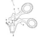
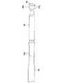
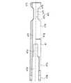
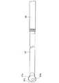
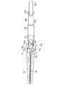
図1〜図25は本発明の第1の実施形態を示している。図1に示すように、本実施形態に係る内視鏡用鉗子1は、その機能上、挿入部2(経内視鏡的に体内に挿入可能)と操作部3の2つに分けられる。挿入部2の先端側には先端作用部 (鉗子部)4が位置されている。また、内視鏡用鉗子1は、図2に示されるジョーユニット5と、図3に示されるシースユニット6と、図4に示されるハンドルユニット7とにそれぞれ分解可能となっている。
【0011】
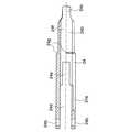
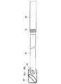
図2に示されるように、ジョーユニット5は、作用部材としての一対のジョー21,22を有する先端作用部4と、ジョー21,22を保持する保持部9と、操作部3からの力をジョー21,22に伝達する軸部10と、操作部3に係合される係合部11とからなる。
【0012】
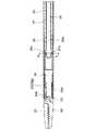
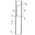
図3に示されるように、シースユニット6は、体腔内に挿入されるシース部12と、先端作用部4の向きを変えるために指で操作されるノブ部13と、シースユニット6内でのジョーユニット5の回転を規制する回転係止部材14とからなる。
【0013】
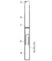
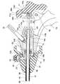
図4に示されるように、ハンドルユニット7は、シースユニット6に連結される固定ハンドル15と、ジョーユニット5の係合部11が連結される可動ハンドル17とからなる。可動ハンドル17は、枢支軸18を介して固定ハンドル15に回動可能に取り付けられている。固定ハンドル15の上端部には、シースユニット6に着脱自在に接続される接続部材16と、高周波通電用のコードが取り付けられる電気接続プラグ19と、シースユニット6とハンドルユニット7との間の気密を保つシールキャップ20とが設けられている。この場合、図8に詳しく示されるように、接続部材16は、電気接続プラグ19によって、固定ハンドル15に固定されている。
【0014】
図5は内視鏡用鉗子1の先端側の断面を示している。図示のように、ジョーユニット5において、保持部材24は先端側に延びる一対のアーム部24a,24aを有している。また、一対のジョー21,22は、枢支軸23を介して保持部材24のアーム部24a,24aに回動自在に取り付けられている。この場合、枢支軸23は、アーム部24a,24aに形成された軸孔24bに固定されている。また、保持部材24の基端部には、雄側バヨネットを形成する係合突起24cが設けられている。
【0015】
保持部材24内には駆動部材25が挿通配置されている。駆動部材25は、保持部材24内を通って基端側へ延在する円筒状の接続部25aを有している。接続部25aの基端には操作棒26が接続されている。操作棒26は、シースユニット6の内部を通ってハンドルユニット7に接続される。
【0016】
図5および図7に示すように、シースユニット6のシース部12は、主管27と、主管27の先端側に嵌着された補強管28と、主管27および補強管28の外周に被覆された電気絶縁性のチューブ29とからなる。なお、チューブ29は例えばテフロンによって形成される。また、補強管28の先端部には、チューブ29の先端面に対して前方側から当接するフランジ部28aが形成されている。このフランジ部28aは、シース部12の先端を補強して落下や衝突に対して対抗するとともに、チューブ29の先端の位置決め部材として機能する。
【0017】
図7に詳しく示すように、主管27の先端側には、外径縮径部27fと内径拡径部27gとが形成されている。内径拡径部27gの内面には、雌側バヨネットを形成するL字型の一対の係合溝27a,27aが設けられている。これらの係合溝27a,27aは、軸方向に延びて主管27の先端面27dで開放される縦溝27bと周方向に延びる横溝27cとからなり、図5、図6(図5のA−A線に沿う断面図)、図16に示すように、保持部材24の係合突起24cが係合できるように形成されている。なお、組み立てられた図5(図17)の状態では、図21(図17のD−D線に沿う断面図)に示されるように、 係合突起21cは、時計回りに回動されて横溝27cの終端に突き当てられている。また、主管27の先端面27dには、係合部突起24cを係合溝27a内に案内するガイド面27eが形成されている(図16参照)。
【0018】
図8に示されるように、主管27の基端部には回転係止部材14が接続固定されている。 主管27と回転係止部材14との接続方法としては、溶接、ロウ付け、半田付け、接着等を挙げることができる。回転係止部材14の基端部は二股状に延びており、その二股に延びる各部の端部は、互いに平行に対向する板バネ状の平面(以下、回転係止部14aという)を形成している。なお、回転係止部材14には、主管27に嵌合される嵌合孔14cと、その内径が嵌合孔14cの内径よりも小さく設定された通孔14dと、固定ハンドル15に固定された接続部材16に突き当てられるフランジ部14bとが設けられている。また、回転係止部材14には、フランジ部14bに隣接してシールリング32が被嵌されている。
【0019】
主管27の基端部および回転係止部材14の外周には略筒状のノブ30が取り付けられている。ノブ30には、その径方向に沿ってガイド孔30aが穿設されている。ガイド孔30aにはL字型の連結部材33が挿入して取り付けられている。ノブ30の内側に位置する連結部材33の一端部は、略フック状に折り曲げられた係合部33aを形成している。ノブ30の外側に突出する連結部材33の他端部には取付け片34が取り付けられており、この取付け片34にはラバースプリング35が被着されている。
【0020】
操作棒26の基端には係合部材36が取り付けられている。係合部材36の外面には、 互いに平行に対向する一対の平面36a,36aが切削形成されている。これらの平面36a,36aに回転係止部材14の回転係止部14aが係合することにより、 シースユニット6内でのジョーユニット5の回転が規制される。また、係合部材36の基端には略球状の係合部36bが形成されている。この係合部36bは、操作棒26と同軸で且つ同径の円筒状の側面部36cと、側面部36cの両側に位置する球面部36g,36gとを有している。
【0021】
なお、図8に示す組立状態でシースユニット6から外部に突出する係合部材36の部位には、電気絶縁性のチューブ37が被覆されている。
【0022】
固定ハンドル15に電気接続プラグ19を介して固定された接続部材16の先端部には、連結部材33の係合部33aと係合する接続部16aが形成されている。接続部16aには、係合部33aを収容する収容溝16bと、係合部33aと係合する係合部16cとが形成されている。また、接続部材16には、回転係止部14aを有する回転係止部材14の二股状の部分と嵌合する第1の内孔16dと、係合部材36と嵌合する第2の内孔16eとが形成されている。
【0023】
可動ハンドル17の上端部には係合部材38が固定されている。この係合部材38にはガイド溝38bを有する係合孔38aが設けられており、この係合孔38aには係合部材36の係合部36bが係合し得るようになっている。
【0024】
図9には、主管27と補強管28との取り付け構造が示されている。図示のように、主管27の先端には、多点溶接(スポット溶接、プロジェクション溶接、レーザ溶接、シーム溶接等)によって補強管28が接続固定されている。具体的には、係合溝27aの周囲に沿うように補強管28の外面に所定の間隔で点溶接70が施され、 補強管28の基端の全周にわたって重ね打ち溶接71が施される。補強管28は、係合溝27aの存在によって強度が低下した主管27の先端側を補強するために設けられている。係合溝27aの周囲に沿って点々とスポット状に溶接を行なうことにより、主管27の先端部が径方向内側に倒れ込むことが防止される。なお、点溶接70は、主管27の先端においても周方向に連続して施されている。
【0025】
また、強度維持のためだけであれば、図9のように間隔をあけたスポット溶接でも構わないが、2つの管27,28間の隙間への液体の侵入を阻止する必要がある場合には、間隔をあけることなく連続的に溶接しても良い。
【0026】
また、図9に示される溶接は、重ねた板の一方側から熱流を貫通させることにより重ねた板同士を順次に溶融させる方法である。補強管28の基端部においては、管状部材の端面同士を突き合わせた状態で両者を同時に溶融させることができるため、より確実な溶接が可能であるが、抵抗溶接である通常のスポット溶接法は使えず、レーザービームを使った溶接やTIGやMIG等のアーク溶接が適している。
【0027】
図10には、主管27と回転係止部材14との取り付け構造が示されている。図示のように、主管27の基端には、多点溶接(スポット溶接、プロジェクション溶接、レーザ溶接、シーム溶接等)によって回転係止部材14が接続固定されている。具体的には、気密性確保のため、回転係止部材14の先端の全周にわたって連続的に重ね打ち溶接71が施される。なお、溶接部以外の嵌合部にシール部材を配設すれば、間隔をあけたスポット溶接でも良い。
【0028】
図11には、駆動部材25と操作棒26との取付け構造が示されている。図示のように、保持部材24の基端から突出する駆動部材25の部位すなわち接続部25aには、 ネジ穴25bと嵌合穴25cと当接端面25dとが形成されている。一方、図12にも示されるように、操作棒26の先端部には、ネジ部26aと嵌合部26bと当接端面26cとが形成されている。駆動部材25と操作棒26とを取り付ける場合には、ネジ部26aをネジ穴25bに捩じ込むとともに、嵌合部26bを嵌合穴25cに嵌合させて当接端面25d,26c同士を当接させる。ネジ部26aをネジ穴25bに捩じ込むことによって両者25,26が仮固定されるとともに操作時の荷重負担が軽減される。また、嵌合部26bを嵌合穴25cに嵌合させることによって、駆動部材25の中心軸に対して操作棒26の中心軸がずれてしまうことを防止できる。また、当接端面25d,26c同士を当接させることによって駆動部材25と操作棒26とを直線的に接続することができる。この取付け状態で、最終的に、両者25,26の接続部(当接端面25d,26c同士の突き当て部)の全周にわたって重ね打ちの突き合わせ溶接72が施される。
【0029】
なお、駆動部材25は機械加工品であるため、ネジ穴(雌ネジ)25bを加工することが容易である。機能上、熱処理が必要であるが、これはネジ加工後に容易に行なえる。また、操作棒26は、その長さに起因して、熱処理不要な硬質材を使用することが経済上適切である。したがって、例えばバネ用鋼材が使用されるが、難加工材であるため、操作棒26には雌ネジよりも加工が容易な雄ネジが形成される。
【0030】
図13には、操作棒26と係合部材36との取り付け構造が示されている。図示のように、係合部材36の先端部には、嵌合穴36dとネジ穴36eと支持穴36fとが形成されている。一方、図14にも示されるように、操作棒26の基端部には、嵌合部26dとネジ部26eと支持部26fとが形成されている。係合部材36と操作棒26とを取り付ける場合には、ネジ部26eをネジ穴36eに捩じ込むことによって、支持穴36fに支持部26fを嵌入するとともに嵌合部26dを嵌合穴36dに嵌合させる。ネジ部26eをネジ穴36eに捩じ込むことによって両者26,36が仮固定されるとともに操作時の荷重負担が軽減される。また、嵌合部26dを嵌合穴36dに嵌合させることによって、係合部材36の中心軸に対して操作棒26の中心軸がずれてしまうことを防止できる。また、支持穴36fに支持部26fを嵌入することによって、係合部材36と操作棒26とを直線的に接続することができる。この取付け状態で、最終的に、両者26,36の接続部(具体的には、嵌合部26dと嵌合される係合部材36の先端部)の全周にわたって重ね打ちの貫通溶接73が施される。
【0031】
なお、操作棒26と係合部材36との固定においては、平行平面である回転係止部36aを周方向(回転方向)で位置合わせする必要があるため、駆動部材25と操作棒26との間の固定のように端面突き合わせ構造を採用することができず、嵌合固定が採用される。嵌合固定では、径方向の隙間が不可避不可欠であるため、2つの部材26,36が傾いた状態で固定されてしまう虞がある。したがって、このような事態を避けるため、本実施形態では、支持部26fによって可能な限り大きなスパンで心出しを行なえるようにしている。なお、支持部26fは、ダイス加工によって難加工材に雄ネジを形成する際に、ダイスを適切にガイドしてネジそのものの傾きを防止する機能を果たす。また、係合部材36は機械加工品であるため、ネジ穴(雌ネジ)36eを加工することが容易である。
【0032】
図15および図17には、ジョーユニット5の先端部の構成が詳細に示されている。各ジョー21,22にはそれぞれ、段差部21d,22dを介して基端側に延在する薄肉のアーム部21c,22cが形成されている。各アーム部21c,22cの端部には、内側に向かって突出するカムピン21e,22eが設けられている。図17に詳しく示されるように、カムピン21e,22eの断面は、真円の円弧を2個所で切り欠いた樽型形状を成している。すなわち、カムピン21e,22eは、円弧状の曲面21g,22gと互いに対向する一対の緩曲面21h,22hとを有している。
【0033】
また、各ジョー21,22には、カム溝としての長円形の孔21a,22aが形成されている。また、これらの孔21a,22aには、ジョー21,22を保持部材24に回動可能に連結する枢支軸23が挿通されている。なお、図17に詳しく示されるように、ジョー22に形成された孔22aは、その先端側の終端から基端側の終端に向かって上方に延びている。また、ジョー21に形成された孔21aは、その先端側の終端から基端側の終端に向かって下方に延びている。
【0034】
また、ジョー21には穴部21bが形成されるとともに、ジョー22には突起22bが形成されている。そして、ジョー22は、その突起22bがジョー21の穴部21bに嵌合されることにより、ジョー21に対して回動可能に連結されている。これにより、2つのジョー21,22は食い違うことなく完全に閉じることができる。
【0035】
なお、図19(図17のB―B線に沿う断面図)に示されるように、各ジョー21,22にはそれぞれ、面取りによって形成された傾斜面21f,22fが設けられている。これらの傾斜面21f,22fは、垂直面に対して60度の傾斜角に設定されているが、45度もしくはそれ以外の傾斜角に設定されていても良い。
【0036】
図15および図22〜図25に示されるように、保持部材24の一対のアーム部24a,24a間には第1のスロット24dが形成されており、この第1のスロット24d内には各ジョー21,22のアーム部21c,22cが嵌入されている。また、保持部材24には、第1のスロット24dよりも基端側に、第1のスロット24dに接続する第2のスロット24eが形成されている。さらに、保持部材24には、駆動部材25の接続部25aが嵌入される嵌合孔24f(図20(図17のC−C線に沿う断面図)参照)と、シースユニット6の主管27の先端面27dと当接する段差状の当接部24gと、当接部24gから基端側に延び且つ基端に係合突起24cを有する小径部24hとが設けられている。なお、図22および図23に詳しく示されるように、係合突起24cは、保持部材24の基端部の幅を円弧状に徐々に狭くするとともに径方向外側に張り出した部分の末端を円弧状に丸めることによって形成されている。
【0037】
駆動部材25の先端部は、各ジョー21,22のアーム部21c,22c間に位置されてこれらアーム部21c,22cによって挟持されている。また、駆動部材25は、アーム部21c,22cに突設されたカムピン21e,22eと係合する一対のカム溝25f,25fを有している。この場合、カムピン21e,22eは、その緩曲面21h,22hで、カム溝25f,25fと係合している(図17参照)。
【0038】
図15および図20に示されるように、駆動部材25は、先端側に形成された2つの段差部25e,25eと、これらの段差部25e,25eから先端側に延びる板状の先端部25g とを有している。板状の先端部25g は保持部材24の第2のスロット24e内に嵌入されており、これにより、駆動部材25はその進退動作(摺動)がガイドされるとともに回転が規制される。すなわち、ジョー21,22の開閉動作時、駆動部材25は2つのカムピン21e,22eからの反力によって回転しようとするため、この回転を阻止すべく第2のスロット24e内に先端部25gが嵌入されている。
【0039】
次に、上記構成の内視鏡用鉗子を組み立てる場合について説明する。
【0040】
図2〜図4に示されるようにジョーユニット5とシースユニット6とハンドルユニット7とが分解されている状態で、まず、ジョーユニット5をシースユニット6に組み付ける。この場合、ジョーユニット5の係合部11をシースユニット6のシース部12の先端から挿入し、係合突起24cを係合溝27aの縦溝27bに係合させる。この時、係合突起24cは、その円弧形状の端部が主管27のガイド面27aに沿って移動することにより、縦溝27b内に容易に導かれる。縦溝27bに係合突起24cが係合した状態でさらにジョーユニット5をシースユニット6内に押し込むと、 係合突起24cが縦溝27bの奥側終端に当接する。この状態で、ジョーユニット5をシースユニット6に対して回転させると、係合突起24cが横溝27cに係合されて横溝27cの終端に突き当てられ(図21の状態)、ジョーユニット5の軸方向の移動が規制される。この時、係合部材36の外面に形成された一対の平面36a,36aが回転係止部材14の回転係止部14aに係合し、シースユニット6内でのジョーユニット5の回転も規制される。
【0041】
なお、このような組立時、横溝27cの奥側終端は係合突起24cの先端側形状と合致する矩形状に形成されているため、横溝27cの終端に隙間なく係合突起24cを当接させることができる。したがって、無駄がなく、主管27の強度の低下を最小限に抑えることができる。また、縦溝27bと横溝27cとの接続部分は、係合突起24cの円弧形状の端部と対応する円弧状に屈曲されているため、係合突起24cが縦溝27bから横溝27cに侵入する際に突起24cと溝27aとが干渉することがない。
【0042】
このようにしてシースユニット6に対するジョーユニット5の組み付けが完了したら、今度はシースユニット6とジョーユニット5とをハンドルユニット7に組み付ける。この場合、固定ハンドル15に固定された接続部材16の接続部16aとノブ30に取り付けられた連結部材33の係合部33aとを係合させるとともに、可動ハンドル17の係合部材38の係合孔38a内にガイド溝38bを通じて係合部材36の係合部36bを係合させる。この場合、連結部材33を上方に付勢するラバースプリング35によって、係合部33aと接続部16a(係合部16c)との係合状態が保持される。
【0043】
次に、組み立てられた内視鏡用鉗子の動作について説明する。
【0044】
図17に示されるようにジョー21,22が完全に閉じられた状態では、枢支軸23が孔21a,22aの先端側終端に位置している。この状態から、可動ハンドル17を反時計回りに回動させると、枢支軸23に対してジョー21,22および駆動部材25が一体となって前進する。したがって、各孔21a,22aの基端側終端が枢支軸23に当接するとともに、カムピン21e,22eがカム溝25f,25fに沿って移動し、図18に示すように、ジョー21,22が突起22bと溝部21bとの嵌合部を支点として回動する。すなわち、駆動部材25の進退によって、突起22bと溝部21bとの嵌合部の前後に位置する2つのカム機構が同時に作用して、ジョー21,22が開閉する。なお、可動ハンドル17の動きは、係合孔38aと係合部36bとの係合によって操作棒26に伝達されるが、この時、係合部36bの円筒状の側面部36cは、その延在方向が操作棒26の進退方向と平行であるため、力の伝達には寄与しない。したがって、側面部36cが力の伝達に悪影響を及ぼすことがない。
【0045】
以上のような動作をもって高周波電流による焼灼処置を行なう場合には、電気接続プラグ19に高周波電源から延びるコードを接続すれば良い。また、挿入部2を体腔内に挿入した場合において、シース部12の先端側からの体腔内のガスの漏洩はシールキャップ20によって防止される。また、傾斜面21f,22fの存在により、直角に近い鋭利な角部がなくなるため、ジョー21,22が生体組織や縫合糸と接触してこれらを傷付けてしまうことがない。また、ジョー21,22を回転させる大きな力が加わった場合には、係合突起24cの側面と横溝27cの側面とが接触してこれに対抗するため、強度的にも格段に優れている。
【0046】
なお、内視鏡用鉗子を洗浄する場合には、ジョーユニット5とシースユニット6とハンドルユニット7とに分解される。分解時は、まず、ラバースプリング35による付勢力に抗して連結部材33を下側に押し下げて、接続部材16の接続部16aと連結部材33の係合部33aとの係合状態を解除し、ジョーユニット5およびシースユニット6をハンドルユニット7から取り外す。次に、シースユニット6に対してジョーユニット5を回転させることにより、回転係止部材14を押し広げつつ平面36a,36aと回転係止部14aとの係合を解除するとともに係合突起24cと横溝27cとの係合を解除する。この状態で、ジョーユニット5をシースユニット6から引き抜けば、ジョーユニット5をシースユニット6から分離することができる。
【0047】
以上説明したように、本実施形態の内視鏡用鉗子は、係合部36bである球の一部を円筒形状に形成している。すなわち、係合部36bは、従来のように完全な球ではなく、操作棒26と同軸で且つ同径の円筒状の側面部36cと、側面部36cの両側に位置する球面部36g,36gとを有している。したがって、ハンドル15,17からの力の伝達性を低下させることなく、係合部36bの外径を小さくできる(側面部36cを設けることによって、力の伝達に大きく寄与する球面部36g,36gの外径をある程度大きく維持しつつ(したがって、相対的に首部の外径も大きくなる)、係合部36bの外径を小さくできる)。その結果、シース部12の主管27の内径を小さくして主管27の肉厚を増大させ、シース部12の強度・剛性をアップさせることができる。
【0048】
図26および図27は、本発明の第2の実施形態を示している。なお、本実施形態において、第1の実施形態と共通する構成要素については同一符号を付してその説明を省略する。
【0049】
本実施形態に係る内視鏡用鉗子では、係合突起24cの末端が角ばって形成されている。これに対応して、縦溝27bと横溝27cとの接続部分の形状も円弧状ではなく矩形状に形成されている。なお、それ以外の構成は第1 の実施形態と同一である。したがって、第1 の実施形態と同様の効果を得ることができるとともに、係合溝27aの形成(加工)が容易となる。
【0050】
図28〜図31は本発明の第3の実施形態を示している。なお、本実施形態において、第1の実施形態と共通する構成要素については同一符号を付してその説明を省略する。
【0051】
本実施形態に係る内視鏡用鉗子では、第1の実施形態における操作棒26を省略し、係合部材36を長く延在させて直接に駆動部材25に連結している(係合部材36と操作棒26とが一体となった状態)。係合部材36と駆動部材25との連結形態は、第1の実施形態における操作棒26と係合部材36との連結形態と同一である。すなわち、駆動部材25の基端部には、嵌合部25hとネジ部25iと支持部25jとが形成されており、ネジ部25iをネジ穴36eに捩じ込むことによって、支持穴36fに支持部25iを嵌入するとともに嵌合部25hを嵌合穴36dに嵌合させる。ネジ部25iをネジ穴36eに捩じ込むことによって両者25,36が仮固定されるとともに操作時の荷重負担が軽減される。また、嵌合部25hを嵌合穴36dに嵌合させることによって、係合部材36の中心軸に対して駆動部材25の中心軸がずれてしまうことを防止できる。また、支持穴36fに支持部25jを嵌入することによって、係合部材36と駆動部材25とを直線的に接続することができる。この取付け状態で、最終的に、両者25,36の接続部( 具体的には、嵌合部25hと嵌合される係合部材36の先端部)の全周にわたって重ね打ちの貫通溶接73が施される。なお、それ以外の構成は第1の実施形態と同一である。
【0052】
したがって、第1の実施形態と同一の作用効果を得ることができるとともに、操作棒に相当する係合部材36の部分が大径であるため強度が高い。また、駆動部材25の基端部のネジ部25iが雄ネジであるため、 加工が容易である。また、第1の実施形態に比べて溶接個所が少なくなるため、 組み立てが容易となる。
【0053】
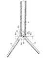
図32〜図44は本発明の第4の実施形態を示している。なお、本実施形態において、第1の実施形態と共通する構成要素については同一符号を付してその説明を省略する。
【0054】
本実施形態に係る内視鏡用鉗子のジョーユニット5は、図32に示されるように、作用部材としての一対のジョー21,22を有する先端作用部4と、ジョー21,22を保持する保持部9と、操作部3からの力をジョー21,22に伝達する軸部10と、操作部3に係合される係合部11とからなる。
【0055】
図33は内視鏡用鉗子の先端側の断面を示している。図示のように、ジョーユニット5において、保持部材24内には板状の駆動部材42が挿通配置されている。駆動部材42には操作棒41が接続されている。操作棒41は、シースユニット6の内部を通ってハンドルユニット7に接続される。
【0056】
図33および図34に示すように、シースユニット6のシース部12は、主管44と、主管27の外周に略全長にわたって被嵌された補強管45と、補強管45の外周に被覆された電気絶縁性のチューブ29とからなる。なお、チューブ29は例えばテフロンによって形成される。また、補強管45の先端部には、チューブ29の先端面に対して前方側から当接するフランジ部45aが形成されている。このフランジ部45aは、シース部12の先端を補強して落下や衝突に対して対抗するとともに、チューブ29の先端の位置決め部材として機能する。
【0057】
図34および図41に詳しく示すように、主管44の先端側の内面には、雌側バヨネットを形成するL字型の一対の係合溝44a,44aが設けられている (第1の実施形態のように、外径縮径部27fと内径拡径部27gとが設けられていない)。これらの係合溝44a,44aは、軸方向に延びて主管44の先端面44dで開放される縦溝44bと周方向に延びる横溝44cとからなり、図33に示すように、保持部材24の係合突起24cが係合できるように形成されている。また、主管44の先端面44dには、係合部突起24cを係合溝44a内に案内するガイド面44eが形成されている。
【0058】
図35に示されるように、主管44の基端部には回転係止部材14が接続固定されている。主管44と回転係止部材14との接続方法としては、溶接、ロウ付け、半田付け、接着等を挙げることができる。主管44の基端部および回転係止部材14の外周には略筒状のノブ30が取り付けられている。なお、補強管45は回転係止部材14の先端面まで達している。
【0059】
操作棒41の基端側の外面には、互いに平行に対向する一対の平面41b,41bが切削形成されている。これらの平面41b,41bに回転係止部材14の回転係止部14aが係合することにより、シースユニット6内でのジョーユニット5の回転が規制される。また、操作棒41の基端には、可動ハンドル17の係合部材38に設けられた係合孔38aに係合される略球状の係合部41gが形成されている。この係合部41gは、操作棒41と同軸で且つ同径の円筒状の側面部41dと、側面部41dの両側に位置する球面部41c,41cとを有している。
【0060】
また、図32に示されるように、操作棒41の先端側には、保持部材24の内部に嵌挿される小径部41aが形成されている。この小径部41aは、図38に示されるように、連結ピン43を介して駆動部材42に連結される。図40に示されるように、駆動部材42は、各ジョー21,22のアーム部21c,22c間に位置されてこれらアーム部21c,22cによって挟持されている。また、図38に詳しく示されるように、駆動部材42は、アーム部21c,22cに突設されたカムピン21e,22eと係合する一対のカム溝42a,42aを有している。
【0061】
図38および図39に示されるように、駆動部材42の基端側には、段差部を介して、 操作棒41の小径部41aと接続される接続部42bが形成されている。また、接続部42bには、操作棒41と駆動部材42とを連結する連結ピン43が挿通されるピン穴42cが設けられている。一方、小径部41aの先端部には、駆動部材42の接続部42bが嵌入されるスロット部41eと、連結ピン43が挿通されるピン穴41fとが形成されている。
【0062】
図36には、シース部12の先端側における主管44と補強管45との取り付け構造が示されている。図示のように、主管44の先端には、多点溶接(スポット溶接、プロジェクション溶接、レーザ溶接、シーム溶接等)によって補強管45が接続固定されている。具体的には、係合溝27aが位置する部位を除く補強管45の先端部の全周面にわたって均等の間隔で点溶接70が施される。
【0063】
図37には、シース部12の基端側における主管44と補強管45との取り付け構造および主管27と回転係止部材14との取り付け構造が示されている。図示のように、主管44の基端部と補強管45の基端部は、多点溶接(スポット溶接、プロジェクション溶接、レーザ溶接、シーム溶接等)によって接続固定されている。具体的には、係合部材14の先端面に突き当てられる補強管45の基端の全周にわたって重ね打ち溶接が施されるとともに補強管45の基端部の周面に均等に点溶接71Aが施される。また、主管44の基端には、多点溶接(スポット溶接、プロジェクション溶接、レーザ溶接、シーム溶接等)によって回転係止部材14が接続固定されている。具体的には、気密性確保のため、回転係止部材14の先端の全周にわたって連続的に重ね打ち溶接71Bが施される。
【0064】
上記構成から分かるように、本実施形態の内視鏡用鉗子は、第1の実施形態において駆動部材25から係合部材36までの円筒状の部分を極力一体化した構造となっている。したがって、第1の実施形態と同様に動作して同様の効果を得ることができる。特に、本実施形態では、回転係止部14aの位置合わせが不要であるため、組立が容易となる。また、部品点数が少なく構造が簡単であるため、製造コストを低く抑えることが可能となる。さらに、連結ピン43を過負荷時の破断部とすることによって、安全な破壊形態とすることができる。なお、本実施形態の場合、連結ピン43は、保持部材24の嵌合孔24fを形成する両側壁によって挟持されているため、抜け落ちることがなく、したがって、固定を要しない。
【0065】
図45〜図47は本発明の第5の実施形態を示している。なお、本実施形態において、第4の実施形態と共通する構成要素については同一符号を付してその説明を省略する。
【0066】
本実施形態に係る内視鏡用鉗子は、第4の実施形態において操作棒41から係合部材36を分離して別体とした構造となっている。すなわち、図45に示すように、駆動部材42の基端に操作棒46が接続され、操作棒46の基端に係合部材36が接続されている。
【0067】
具体的には、図46および図47に示されるように、駆動部材42の基端側には、段差部を介して、操作棒46の先端部と接続される接続部42bが形成されている。また、接続部42bには、操作棒46と駆動部材42とを連結する連結ピン43が挿通されるピン穴42cが設けられている。一方、操作棒46の先端部には、駆動部材42の接続部42bが嵌入されるスロット部46bと、連結ピン43が挿通されるピン穴46cとが形成されている。また、操作棒46と係合部材36との取り付け方法は、第1の実施形態と同様である。すなわち、図47に示されるように、操作棒46の基端部には、嵌合部46dとネジ部46eと支持部46fとが形成されており、ネジ部46eをネジ穴36eに捩じ込むことによって、支持穴36fに支持部46fを嵌入するとともに嵌合部46dを嵌合穴36dに嵌合させる。この取付け状態で、最終的に、両者46,36の接続部 (具体的には、嵌合部46dと嵌合される係合部材36の先端部)の全周にわたって重ね打ちの貫通溶接73が施される。
【0068】
図48〜図50は本発明の第6の実施形態を示している。本実施形態の内視鏡用鉗子は、保持部材24の形状が第1の実施形態と異なる。すなわち、図48〜図50に示すように、本実施形態の保持部材47は、先端側に延びる一対のアーム部47a,47aを有している。アーム部47a,47aには、枢支軸23を介して、一対のジョー21,22が回動自在に取り付けられる。この場合、枢支軸23は、 アーム部47a,47aに形成された軸孔47bに固定される。また、保持部材47の基端部には、雄側バヨネットを形成する係合突起47cが設けられている。係合突起47cは、シース部12の主管27のガイド面27eに対応した形状(例えば弦巻線状)を成すガイド面47lが形成されている。
【0069】
保持部材47の一対のアーム部47a,47a間には第1のスロット47dが形成されており、この第1のスロット47d内には各ジョー21,22のアーム部21c,22cが嵌入される。また、保持部材47には、第1のスロット47dよりも基端側に、第1のスロット47dに接続する第2のスロット47eが形成されている。さらに、保持部材47には、駆動部材25の接続部25aが嵌入される嵌合孔47fと、シースユニット6の主管27の先端面27dと当接する段差状の当接部47gと、当接部47gから基端側に延び且つ基端に係合突起24cを有する小径部47hとが設けられている。小径部47hには、基端部47jから所定の長さにわたって削り込むことによって形成されたブリッジ部47kが設けられている。
【0070】
第1の実施形態では、係合突起24cが保持部材24の基端で片持ち梁状に突出しているが、本実施形態では、係合突起47cが両側から強固に支持されている。このような構成によれば、係合突起47cを支持する部分の強度が向上し、変形の虞が減少する。
【0071】
図51〜図69は本発明の第7の実施形態を示している。なお、本実施形態において、第4の実施形態と共通する構成要素については同一符号を付してその説明を省略する。
【0072】
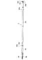
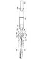
図51に示されるように、本実施例の内視鏡用鉗子のジョーユニット5は、把持・剥離を行なうための第1および第2のジョー51,52と、 ハンドルユニット7に連結され且つハンドルユニット7の操作力によって進退する操作棒50と、操作棒50とジョー51,52とを連結してハンドルユニット7の操作力をジョー51,52に伝達する駆動部材57と、ジョー51,52および駆動部材57を保持する保持部材53とを有している。操作棒50の基端側の外面には、互いに平行に対向する一対の平面50a,50aが切削形成されている。これらの平面50a,50aに回転係止部材14の回転係止部14aが係合することにより、シースユニット6内でのジョーユニット5の回転が規制される。また、操作棒50の基端には、可動ハンドル17の係合部材38に設けられた係合孔38aに係合される略球状の係合部50gが形成されている。この係合部50gは、操作棒50と同軸で且つ同径の円筒状の側面部50cと、側面部50cの両側に位置する球面部50b,50bとを有している。
【0073】
図53には、操作棒50と駆動部材57との取り付け構造が示されている。図示のように、操作棒50の先端部には、嵌合穴50dとネジ穴50eと支持穴50fとが形成されている。また、駆動部材57の基端部には、嵌合部57dとネジ部57eと支持部57fとが形成されている。駆動部材57と操作棒50とを取り付ける場合には、ネジ部57eをネジ穴50eに捩じ込むことによって、支持穴50fに支持部57fを嵌入するとともに嵌合部57dを嵌合穴50dに嵌合させる。
【0074】
図56、図57、図67〜図69に詳しく示されるように、保持部材53は、シース部12の先端から前方に延出する先端膨大部53aと、先端膨大部53bから基端側に延びる一対のアーム部53c,53cと、アーム部53c,53c間に形成され且つジョー51,52を挟み込んで保持するスロット部53bと、保持部材53と第2のジョー52とを回動可能に連結する枢支ピン54が挿通される枢支孔53dと、駆動部材57が嵌挿される孔53fと、主管44の先端側の内面に形成された係合溝44a,44aと係合する係合突起53eと、シースユニット6の主管44の先端面44dと当接する段差状の当接部53gと、当接部53gから基端側に延び且つ基端に係合突起53eを有する小径部53hとを有している。なお、外力が加わった際の応力集中を少なくして強度を向上させるために、アーム部53cの基端側は円弧状に形成されている。また、枢支ピン54は、その両端が保持部材53に溶接等によって固定されている。
【0075】
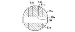
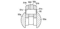
図54、図55、図60〜図63に詳しく示されるように、第1のジョー51は、その基端側に一対のアーム部51b,51bを有している。アーム部51b,51b間にはスロット51aが形成されている。 また、第1のジョー51には、第1のジョー51と第2のジョー52とを回動可能に連結するための枢支ピン55が挿通される枢支孔51cと、第1のジョー51と駆動部材57の先端部とを回動可能に連結するための枢支ピン56が挿通される枢支孔51dとが形成されている。なお、枢支ピン55,56は、第1および第2のジョー51,52のいずれにも固定されていない。
【0076】
第2のジョー52は、保持部材53のスロット部53bに嵌入される第1の嵌入部52aと、枢支ピン54が挿通される枢支孔52bと、第1のジョー51のスロット部51aに嵌入される第2の嵌入部52cと、枢支ピン55が挿通される枢支孔52dと、ジョー51,52を完全に開いた際に駆動部材57の後述する当接部57cと当接(図58参照)する当接部52eとを有している。
【0077】
また、図64〜図66に示されるように、第2のジョー52の把持面には、挿入部2の長手軸方向に対して傾斜して形成された歯52fと、挿入部2の長手軸方向と略平行に配列して設けられた台形もしくは矩形状の縦溝52gと、把持面の外周縁部に挿入部2の長手軸方向と略平行に配列して設けられた傾斜面52hとが形成されている。 この場合、歯52fは把持対象組織に食い付くことができ、また、縦溝52gには把持対象組織が食い込む。特に、縦溝52gは、ここに把持対象組織が食い込むことによって、横滑り( 歯52fに沿った方向の滑り)を阻止する。なお、図65に示されるように、傾斜面52hの傾斜角度は垂直方向に対して30°に設定されるとともに、互いに対向する傾斜面52h,52h同士の開き角は40°に設定されている。あるいは、図66に示されるように、傾斜面52hの傾斜角度を垂直方向に対して45°に設定して、互いに対向する傾斜面52h,52h同士の開き角を90°に設定しても良い。図65に示されるように角度を設定すると、洗浄性が良好となり、また、図66に示されるように角度を設定すると、加工性が良好となる。
【0078】
図54〜図57に示されるように、駆動部材57は、第1のジョー51のスロット部51aに嵌入する偏平部57aと、枢支ピン56が挿通される枢支孔57bと、ジョー51,52を完全に開いた際に第2のジョー52の当接部52eと当接する当接部57cとを有している。
【0079】
したがって、上記構成によれば、可動ハンドル17が操作されることによって操作棒50および駆動部材57が進退し、枢支ピン55,56の移動によってジョー51,52が開閉動作される。なお、この場合、当接部52e,57c同士が当接することにより開方向の動作が規制される(図59参照)。また、ジョー51,52の先端同士が当接することにより、閉方向の動作が規制される。
【0080】
なお、本実施形態では、膨大部53aによって枢支ピン55の両端部が保持され、また、アーム部53cによって枢支ピン56の両端部が保持されている。したがって、枢支ピン55,56は、固定されていなくても脱落することがない。また、枢支ピン55は、ジョー51,52の全開時(図58図参照)に、図63に示されるように変位するが、この時にもアーム部53cによって部分的に保持されているため、脱落することがない。
【0081】
以上説明したように、本実施形態の内視鏡用鉗子によれば、第および第4の実施形態と同様の作用効果を得ることができるとともに、駆動機構57の形状によって、強度が高くなり、ガタ付きおよび摩耗の少ない構造となる。
【0082】
図70〜図77は本発明の第8の実施形態を示している。なお、本実施形態において、第4および第7の実施形態と共通する構成要素については同一符号を付してその説明を省略する。
【0083】
図70〜図72に示されるように、本実施形態の内視鏡用鉗子は、把持・剥離を行なうための第1および第2のジョー58,52と、ハンドルユニット7の操作力をジョー58,52に伝達する操作棒59と、ジョー58,52および駆動部材59を保持する保持部材53とを有している。
【0084】
図73および図74に示されるように、第1のジョー58は、その基端側に一対のアーム部58b,58bを有している。 アーム部58b,58b間には、第2のジョー52の嵌入部52cが嵌入されるスロット部58aが形成されている。また、第1のジョー58には、枢支ピン55が挿通される枢支孔58cと、枢支ピン56が挿通される枢支孔58dとが形成されている。
【0085】
操作棒59は、第1のジョー58のスロット部58aに嵌入される偏平部59eと、枢支56が挿通される枢支孔59fと、ジョー58,52を完全に開いた際に第2のジョー52の当接部52eと当接(図75および図76参照)する当接部59gとを有している。また、操作棒59の基端側の外面には、互いに平行に対向する一対の平面59a,59aが切削形成されている。これらの平面59a,59aに回転係止部材14の回転係止部14aが係合することにより、シースユニット6内でのジョーユニット5の回転が規制される。また、操作棒59の基端には、可動ハンドル17の係合部材38に設けられた係合孔38aに係合される略球状の係合部59hが形成されている。この係合部59hは、操作棒59と同軸で且つ同径の円筒状の側面部59cと、側面部59cの両側に位置する球面部59b,59bとを有している。また、操作棒59の先端側には、保持部材53の孔53f内に嵌入される小径の嵌合部59dが形成されている。
【0086】
なお、第7の実施形態では、枢支ピン56が挿入部2の中心軸よりも僅かに下側に位置されていたが、本実施形態では、枢支ピン56が挿入部2の中心軸に一致している。このように、枢支ピン56が挿入部2の中心軸に一致しても、全開時および全閉時においてジョー58,52の位置は第7の実施形態と略同じであり、使用上、問題はない。このように枢支ピン56を挿入部2の中心軸に一致ささせることによって、枢支ピン56周りの部材がすべてアーム部53cの高さ範囲内に収まり(図77参照)、捻りに対する強度がアップする。また、枢支ピン54を枢支ピン56と同様に挿入部2の中心軸上に一致させても同様の機構を構成できる。
【0087】
以上説明したように、本実施形態の内視鏡用鉗子によれば、駆動部材と操作棒と係合部材とが一体となって1つの操作棒59を形成しているため、構造が簡単となり、製造コストの低減を図ることができる(旋盤加工が不要。単に棒状部材の先端を板状に形成して穴をあけるだけで済む)。また、回転方向の位置合わせが不要となり、組立性が向上される。
【0088】
図78〜図83は本発明の第9の実施形態を示している。なお、本実施形態において、第4の実施形態と共通する構成要素については同一符号を付してその説明を省略する。
【0089】
図78〜図80に示すように、本実施例の内視鏡用鉗子は、切断を行なうための第1および第2のブレード61,62と、ハンドルユニット7に連結され且つハンドルユニット7の操作力によって進退する操作棒66と、操作棒66とブレード61,62とを連結してハンドルユニット7の操作力をブレード61,62に伝達する駆動部材65と、ブレード61,62および駆動部材65を保持する保持部材64とを有している。
【0090】
各ブレード61,62は、枢支軸63が挿通される枢支孔61a,62aと、段差部61c,62cを介して基端側に薄く延在して駆動部材65を挟持するアーム部61b,62bと、アーム部61b,62bの基端に設けられ且つ駆動部材65に形成されたカム溝65aと係合するカムピン61d,62dとを有している。なお、枢支軸63には、円錐面を有する円筒形状の拡径部63aと、ネジ部63bとが設けられている。
【0091】
図81〜図83に詳しく示されるように、保持部材64は先端側に延びる一対のアーム部64a,64aを有している。 これらのアーム部64a,64aには、一対のブレード61,62が枢支軸63を介して回動自在に取り付けられている。この場合、枢支軸63は、アーム部64a,64aに形成された軸孔64bに固定されている。また、保持部材64の基端部には、雄側バヨネットを形成する係合突起64cが設けられている。この係合突起64cは雌側バヨネットを形成する主管44の係合溝44aに係合される。なお、保持部材64は、枢支軸63の拡径部63aが嵌合される座ぐり部64iと、枢支軸63のネジ部63bと螺合するネジ部64jと、シース部12の先端から突出する延長部64kとを有している。この場合、延長部64kは、2つのブレード61,62をこれらブレードの中央に近い部分で圧迫してより効果的に相互接触させる作用をなす。このように延長部64kを設けると、硬い対象物を切断しようとする時に、ブレード61,62同士が相互に離反しようとする傾向が防止され、切断能力が向上する。
【0092】
保持部材64内には駆動部材65が挿通配置されている。駆動部材65は、保持部材64内を通って基端側へ延在する円筒状の接続部65bを有している。接続部65bの基端には操作棒66が接続されている。操作棒66は、シースユニット6の内部を通ってハンドルユニット7に接続される。
【0093】
保持部材64の一対のアーム部64a,64a間には第1のスロット64dが形成されており、この第1のスロット64d内には各ブレード61,62のアーム部61b,62bが嵌入されている。また、保持部材64には、第1のスロット64dよりも基端側に、第1のスロット64dに接続する第2のスロット64eが形成されている。さらに、保持部材64には、駆動部材65の接続部65bが嵌入され且つ操作棒66のアーム部66cが収容される嵌合孔64fと、シースユニット6の主管44の先端面44dと当接する段差状の当接部64gと、当接部64gから基端側に延び且つ基端に係合突起64cを有する小径部64hとが設けられている。
【0094】
駆動部材65の先端部は、各ブレード61,62のアーム部61b,62b間に位置されてこれらアーム部61b,62bによって挟持されている。また、駆動部材65は、アーム部61b,62bに突設されたカムピン61d,62dと係合する一対のカム溝65a,65aを有している。
【0095】
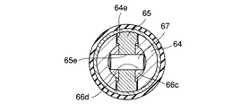
駆動部材65は、先端側に形成された2つの段差部65c,65cと、 これらの段差部25e,25eから先端側に延びる板状の先端部65g とを有している。板状の先端部65g は保持部材64の第2のスロット64e内に嵌入されるとともに操作棒66のアーム部66cに挟まれており、これにより、駆動部材65はその進退動作(摺動)がガイドされるとともに回転が規制される。また、接続部65bには、操作棒66を取り付けるために、長円形孔65eと円形孔65fとが形成されている。長円形孔65eには確保ピン67が挿通され、円形孔65fには確保ピン67よりも小径の破断ピン68が挿通される。
【0096】
なお、操作棒66は、保持部材64の嵌合孔64f内に挿通可能な外径に設定された小径部66aと、スロット部66bと、ピン取付孔66d,66eとを有している。
【0097】
上記構成では、操作棒66の進退によって駆動部材65が進退され、 枢支軸63の基端側にのみ設けられたカム機構によってブレード61,62が開閉される。したがって、対象組織を切断することができる。なお、過大な操作力が生じた場合には、破断ピン68が先に破断する。その後は、確保ピン67によって大きいガタを伴ってブレード61,62の開閉動作が可能となる。
【0098】
なお、本実施形態において、ブレード61,62の表面には、Ti−C、Ti−N等のセラミックコーティングが施されている。また、カムピン61d,62dの表面にも被膜が形成されている。この被膜は摺動面の保護被膜として作用する。カム溝65aの摺動面には被膜を形成しない。カム溝65aは、相対的に広い面で摺動するため、単位面積当たりの摩耗量が少なく、熱処理のみで十分であるからである。同じ硬度の面同士の摺動により面積の少ない方が先に摩耗してしまう現象を避けるためにも、被膜がない方が良い。また、摺動する部分においては、材質を異にする方が焼き付きやかじり付きの防止のためにも好ましい。
【0099】
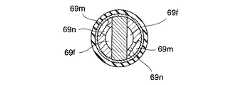
図84〜図86は本発明の第10の実施形態を示している。本実施形態の内視鏡用鉗子は、保持部材の形状が第1、第4、第9の実施形態(以下、これら各実施形態と共通する構成要素については同一符号を付してその説明を省略する)と異なる。すなわち、保持部材69は、その軸方向に形成された送水路69mと、送水路69mの先端部に形成された送水孔69nとを有している。この場合、送水路69mは係合溝44aの縦溝44bと一致する。また、送水孔69nは、径方向に延びて嵌合孔69f(駆動部材65の接続部65bが嵌入され且つ操作棒66のアーム部66cが収容される)に連通している。
【0100】
このような構成では、組立完成時、縦溝44bと送水路69mとが一致して軸方向の通路となる。主管44と操作棒26との隙間を通った流体は、縦溝44bから送水路69mに流入し、送水孔69nを経て、嵌合孔69fに到達する。その後、流体は、第2のスロット69e(第9の実施形態の第2のスロット64eに相当)および第1のスロット69d(第9の実施形態の第1のスロット64dに相当)を通って先端から流出する。ノブ30に適切な流体の流入口を設けておけば、洗浄通路として使用することができる。
【0101】
なお、以上説明してきた技術内容によれば、以下に示すような各種の構成が得られる。
【0102】
1.操作部と、挿入部と、一対のジョーを有する先端作用部とからなる内視鏡用鉗子において、
先端作用部に軸方向の往復動の力を伝達する操作棒を、前記挿入部の内部に設け、
操作棒の基端に、前記操作部の可動ハンドルに係合する球部を設け、
球部の外周を、操作棒と同軸の円筒形状に形成した、
ことを特徴とする内視鏡用鉗子。
【0103】
2.操作部と、挿入部と、一対のジョーを有する先端作用部とからなる内視鏡用鉗子において、
先端作用部に軸方向の往復動の力を伝達する操作棒を、前記挿入部の内部に設け、
操作棒の基端に、前記操作部の可動ハンドルに係合する球部を設け、
球部の外周を、前記挿入部の内径に適合した外径の円筒状に形成した、
ことを特徴とする内視鏡用鉗子。
【0104】
3.操作部と、挿入部と、一対のジョーを有する先端作用部とからなり、先端作用部に軸方向の往復動の力を伝達する操作棒を前記挿入部の内部に設け、前記操作部の可動ハンドルに係合する球部を操作棒の基端に設けた内視鏡用鉗子において、
球部の外周を前記挿入部の内径に適合した外径の円筒状に形成したことを特徴とする内視鏡用鉗子。
【0105】
4.操作部と、挿入部と、一対のジョーを有する先端作用部とからなり、先端作用部に軸方向の往復動の力を伝達する操作棒を前記挿入部の内部に設け、前記操作部の可動ハンドルに係合する球部を操作棒の基端に設けた内視鏡用鉗子において、
球部の外周を、前記挿入部の内径に適合した外径の円筒状に形成し、
操作棒の略全長にわたる部分の外径を、前記円筒状の部分の外径に略等しくした、
ことを特徴とする内視鏡用鉗子。
【0106】
5.操作部と、シース部と、一対のジョーを有し前記操作部と係合する操作棒を有する作用部とからなり、前記操作部の可動ハンドルに係合する球部を操作棒の基端に設け、前記各部が相互に連結・分離可能な内視鏡用鉗子において、
球部の外周を前記挿入部の内径に適合した外径の円筒状に形成したことを特徴とする内視鏡用鉗子。
【0107】
【発明の効果】
以上説明したように、本発明の内視鏡用鉗子によれば、挿入部の強度を低下させることなく操作力の伝達効率を向上させることができる。
【図面の簡単な説明】
【図1】本発明の第1の実施形態に係る内視鏡用鉗子の側面図である。
【図2】図1の内視鏡用鉗子を構成するジョーユニットの側面図である。
【図3】図1の内視鏡用鉗子を構成するシースユニットの側面図である。
【図4】図1の内視鏡用鉗子を構成するハンドルユニットの側面図である。
【図5】図1の内視鏡用鉗子の先端側の側断面図である。
【図6】図5のA−A線に沿う断面図である。
【図7】シースユニットのシース部の側断面図である。
【図8】図1の内視鏡の操作部側の側断面図である。
【図9】主管と補助管との取り付け構造を示す断面図である。
【図10】主管と回転係止部材との取り付け構造を示す断面図である。
【図11】操作棒と駆動部材との取り付け構造を示す断面図である。
【図12】操作棒の先端部の側面図である。
【図13】操作棒と係合部材との取り付け構造を示す断面図である。
【図14】操作棒の基端部の側面図である。
【図15】ジョーユニットの先端部の一部断面を付した平面図である。
【図16】シースユニットの先端部の断面図である。
【図17】図1の内視鏡用鉗子の先端部の断面図(ジョー全閉時)である。
【図18】図1の内視鏡用鉗子の先端部の断面図(ジョー全開時)である。
【図19】図17のB−B線に沿う断面図である。
【図20】図17のC−C線に沿う断面図である。
【図21】図17のD−D線に沿う断面図である。
【図22】保持部材の一部断面を付した平面図である
【図23】保持部材の一部断面を付した側面図である。
【図24】保持部材の先端側正面図である
【図25】保持部材の基端側正面図である。
【図26】本発明の第2の実施形態に係る内視鏡用鉗子のジョーユニットの先端側平面図である。
【図27】第2の実施形態に係る内視鏡用鉗子のシースユニットの先端側断面図である。
【図28】本発明の第3の実施形態に係る内視鏡用鉗子のジョーユニットの側面図。
【図29】係合部材と駆動部材との取り付け構造を示す側面図である。
【図30】係合部材と駆動部材との取り付け構造を示す断面図である。
【図31】係合部材の基端部の側面図である。
【図32】本発明の第4の実施形態に係る内視鏡用鉗子のジョーユニットの側面図。
【図33】第4の実施形態に係る内視鏡用鉗子の先端側の断面図である。
【図34】第4の実施形態に係るシースユニットの先端側断面図である。
【図35】第4の実施形態に係る内視鏡用鉗子の操作部側の断面図である。
【図36】主管と補助管との取り付け構造を示す断面図である。
【図37】回転係止部材と主管との取り付け構造を示す断面図である。
【図38】操作棒と駆動部材との連結部の側面図である。
【図39】操作棒と駆動部材の連結部の一部断面を付した平面図である。
【図40】ジョーユニットの先端側の一部断面を付した平面図である。
【図41】シースユニットの先端側断面図である。
【図42】第4の実施形態に係る内視鏡用鉗子の先端部の断面図(ジョー全閉時)。
【図43】第4の実施形態に係る内視鏡用鉗子の先端部の断面図(ジョー全開時)。
【図44】図42のE−E線に沿う断面図である。
【図45】本発明の第5の実施形態に係る内視鏡用鉗子のジョーユニットの側面図。
【図46】駆動部材と操作棒と係合部材との取り付け構造を示す側面図である。
【図47】駆動部材と操作棒と係合部材との取り付け構造を示す一部断面を付した平面図である。
【図48】本発明の第6の実施形態に係る内視鏡用鉗子の保持部材の一部断面を付した平面図である。
【図49】図48の保持部材の一部断面を付した側面図である。
【図50】図48の保持部材の基端側正面図である。
【図51】本発明の第7の実施形態に係る内視鏡用鉗子のジョーユニットの側面図。
【図52】操作棒と駆動部材との取り付け構造を示す側面図である。
【図53】操作棒と駆動部材との取り付け構造を示す断面図である。
【図54】第7の実施形態に係る内視鏡用鉗子の先端側(全閉時)の中心断面図。
【図55】第7の実施形態に係る内視鏡用鉗子の先端側(全閉時)のオフセット断面図である。
【図56】第7の実施形態に係る内視鏡用鉗子の先端側(全閉時)の側面図である。
【図57】第7の実施形態に係る内視鏡用鉗子の先端側(全閉時)の一部断面を付した平面図である。
【図58】第7の実施形態に係る内視鏡用鉗子の先端側(全開時)の中心断面図。
【図59】第7の実施形態に係る内視鏡用鉗子の先端側(全開時)のオフセット断面図である。
【図60】図55のF−F線に沿う断面図である。
【図61】図55のG−G線に沿う断面図である。
【図62】図55のH−H線に沿う断面図である。
【図63】図58のJ−J線に沿う断面図である。
【図64】ジョーの平面図である。
【図65】図64のK方向矢視図である。
【図66】図64のK方向矢視図である。
【図67】第7の実施形態に係る内視鏡用鉗子の保持部材の一部断面を付した平面図である。
【図68】図67の保持部材の一部断面を付した側面図である。
【図69】図67の保持部材の正面図である。
【図70】本発明の第8の実施形態に係る内視鏡用鉗子のジョーユニットの側面図。
【図71】操作棒の拡大側面図である。
【図72】操作棒の先端側平面図である。
【図73】第8の実施形態に係る内視鏡用鉗子の先端側(全閉時)の中心断面図である。
【図74】第8の実施形態に係る内視鏡用鉗子の先端側(全閉時)のオフセット断面図である。
【図75】第8の実施形態に係る内視鏡用鉗子の先端側(全開時)の中心断面図である。
【図76】第8の実施形態に係る内視鏡用鉗子の先端側(全開時)のオフセット断面図である。
【図77】図74のL−L線に沿う断面図である。
【図78】本発明の第9の実施形態に係る内視鏡用鉗子の先端側の一部断面を付した平面図である。
【図79】図78の内視鏡用鉗子の先端側の側面図である。
【図80】図79のM−M線に沿う断面図である。
【図81】第9の実施形態に係る内視鏡用鉗子の保持部材の一部断面を付した平面図である。
【図82】第9の実施形態に係る内視鏡用鉗子の保持部材の一部断面を付した側面図である。
【図83】図82の保持部材の正面図である。
【図84】本発明の第10の実施形態に係る内視鏡用鉗子の先端側の断面図である。
【図85】図84のN−N線に沿う断面図である。
【図86】図84の内視鏡用鉗子の先端側の一部断面を付した平面図である。
【符号の説明】
1…内視鏡用鉗子
2…挿入部
3…操作部
4…先端作用部(鉗子部)
15…固定ハンドル
17…可動ハンドル
26,41,46,50,59,66…操作棒(操作軸)
36,39…係合部材(操作軸)
36b…係合部
36c…側面部
36g…球面部[0001]
BACKGROUND OF THE INVENTION
The present invention relates to an endoscopic forceps that is inserted into a body cavity through a transendoscope to treat an affected tissue.
[0002]
[Prior art]
Endoscopic forceps for endoscopically inserting into a body cavity to treat an affected tissue include, for example, an operation unit including a fixed handle and a movable handle, as disclosed in US Pat. No. 5,342,391. An insertion portion that is connected and can be inserted endoscopically into a body cavity, a treatment portion provided on the distal end side of the insertion portion, and inserted into the insertion portion so as to be able to advance and retreat, and connect the operation portion and the treatment portion. It has an operation bar. The operating rod is connected to the operating portion when an engaging portion formed at a base end thereof is engaged with the movable handle, and moves forward and backward in the insertion portion according to the operation of the movable handle to operate the treatment portion.
[0003]
The engaging portion formed at the base end of the operating rod has an outer diameter set to be substantially the same as the outer diameter of the operating rod (the operating rod is inserted into the inserting portion together with the ball portion and assembled, And a neck portion that connects the sphere portion to the operation rod. The engaging portion is connected to the movable handle when the ball portion is engaged in the blind hole in the movable handle by hooking the neck portion on the slot formed in the movable handle. Further, the range of movement of the movable handle is limited by the engagement between the leaf spring and the hook, which prevents the operating rod from being detached from the operating portion during use. When the operating rod is removed from the operating portion, the engagement between the leaf spring and the hook is released to expand the moving range of the movable handle, and the engaged state between the engaging portion and the movable handle is released.
[0004]
Further, in the endoscopic forceps disclosed in EP 0 484 671 B1, a square groove is formed at the base end of the operation rod, and the operation rod is moved from both sides by two disks in which a hooking portion to be hooked is formed. It is pinched. Then, the disk is fitted into a circular hole formed on the side surface of the movable handle.
[0005]
[Problems to be solved by the invention]
However, in the endoscopic forceps disclosed in US Pat. No. 5,342,391, the outer diameter of the ball portion of the engaging portion cannot be made larger than the inner diameter of the insertion portion. Therefore, the operating force that can be transmitted from the handle is restricted (the larger the outer diameter of the ball portion, the larger the operating force is transmitted to the treatment portion). On the other hand, if the outer diameter of the sphere is increased in order to obtain a large transmission force, the inner diameter of the insertion section must be increased. Therefore, the thickness of the insertion portion is reduced, and the strength of the insertion portion is reduced. In addition, since the neck diameter is smaller than the sphere diameter, the transmittable operating force is limited (if the ratio of the neck diameter to the sphere diameter is not less than a certain value, the force is good) I can't tell you).
[0006]
Further, in EP 0 484 671 B1, a mechanism for preventing the change in the inclination of the movable handle from affecting the engagement between the engaging portion and the movable handle is required. Therefore, the mechanism becomes complicated.
[0007]
The present invention has been made paying attention to the above circumstances, and the object of the present invention is for an endoscope having a simple structure capable of improving the transmission efficiency of the operating force without reducing the strength of the insertion portion. It is to provide forceps.
[0008]
[Means for Solving the Problems]
In order to achieve the above object,According to the present invention Endoscopy forceps have a fixed handle,this An operation unit including a movable handle rotatably attached to a fixed handle;Said It is fixedly connected to the fixed handle of the operation unit.Inserted into the body An insertion part;An operation rod that is inserted in the insertion portion so as to be able to advance and retreat when the movable handle is rotated, a forceps portion that is disposed at a distal end of the insertion portion that is operated by the advancement and retraction operation of the operation rod, and the movable An engagement hole provided in the handle and formed with a guide groove for engaging the operation rod with the movable handle, and a small-diameter neck portion for engaging the operation rod with the movable handle through the guide groove of the engagement hole. A substantially spherical engagement portion formed at the proximal end of the operation rod with a diameter larger than that of the neck portion, and by a rotation operation to the movable handle, the operation rod is brought into contact with the movable handle in the insertion portion. The same diameter as the spherical surface portion between the spherical portion formed on the distal end side and the proximal end side of the engaging portion to be advanced and retracted at the front and the spherical portion formed on the distal end side and the proximal end side in the engaging portion Cylindrical and front And a side portion formed as an operating rod coaxially It is characterized by having.
[0009]
DETAILED DESCRIPTION OF THE INVENTION
Hereinafter, embodiments of the present invention will be described with reference to the drawings.
[0010]
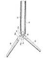
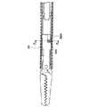
1 to 25 show a first embodiment of the present invention. As shown in FIG. 1, the forceps for endoscope 1 according to the present embodiment is divided into two parts, that is, an insertion part 2 (can be inserted into a body endoscopically) and an operation part 3 in terms of its function. A distal end working part (forceps part) 4 is positioned on the distal end side of the
[0011]
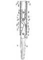
As shown in FIG. 2, the
[0012]
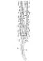
As shown in FIG. 3, the
[0013]
As shown in FIG. 4, the handle unit 7 includes a
[0014]
FIG. 5 shows a cross section of the distal end side of the endoscopic forceps 1. As shown in the drawing, in the
[0015]
A
[0016]
As shown in FIGS. 5 and 7, the
[0017]
As shown in detail in FIG. 7, an outer diameter reduced
[0018]
As shown in FIG. 8, the
[0019]
A substantially
[0020]
An
[0021]
In addition, an electrically insulating
[0022]
A connecting
[0023]
An engaging
[0024]
FIG. 9 shows an attachment structure for the
[0025]
Further, as long as it is only for maintaining the strength, spot welding with an interval as shown in FIG. 9 may be used. However, when it is necessary to prevent liquid from entering the gap between the two
[0026]
Further, the welding shown in FIG. 9 is a method in which the stacked plates are sequentially melted by passing a heat flow from one side of the stacked plates. At the base end portion of the reinforcing
[0027]
FIG. 10 shows an attachment structure between the
[0028]
FIG. 11 shows a mounting structure of the
[0029]
Since the
[0030]
FIG. 13 shows a mounting structure of the operating
[0031]
In fixing the
[0032]
15 and 17 show the configuration of the tip of the
[0033]
Each of the
[0034]
The
[0035]
Note that as shown in FIG. 19 (a cross-sectional view taken along line BB in FIG. 17), the
[0036]
As shown in FIGS. 15 and 22 to 25, a
[0037]
The distal end portion of the
[0038]
As shown in FIGS. 15 and 20, the
[0039]
Next, a case where the endoscope forceps having the above-described configuration is assembled will be described.
[0040]
As shown in FIGS. 2 to 4, with the
[0041]
At the time of such assembly, the rear end of the
[0042]
When the assembly of the
[0043]
Next, the operation of the assembled endoscope forceps will be described.
[0044]
As shown in FIG. 17, in a state where the
[0045]
When cauterization is performed with a high-frequency current with the above operation, a cord extending from a high-frequency power source may be connected to the
[0046]
Note that when the endoscope forceps are washed, the
[0047]
As described above, in the endoscope forceps according to the present embodiment, a part of the sphere that is the engaging
[0048]
26 and 27 show a second embodiment of the present invention. In the present embodiment, the same reference numerals are given to components common to the first embodiment, and the description thereof is omitted.
[0049]
In the endoscopic forceps according to the present embodiment, the end of the engaging
[0050]
28 to 31 show a third embodiment of the present invention. In the present embodiment, the same reference numerals are given to components common to the first embodiment, and the description thereof is omitted.
[0051]
In the endoscope forceps according to the present embodiment, the
[0052]
Therefore, the same operational effects as those of the first embodiment can be obtained, and the strength of the engaging
[0053]
32 to 44 show a fourth embodiment of the present invention. In the present embodiment, the same reference numerals are given to components common to the first embodiment, and the description thereof is omitted.
[0054]
As shown in FIG. 32, the
[0055]
FIG. 33 shows a cross section of the distal end side of the endoscopic forceps. As shown in the figure, in the
[0056]
As shown in FIGS. 33 and 34, the
[0057]
As shown in detail in FIGS. 34 and 41, a pair of L-shaped
[0058]
As shown in FIG. 35, the
[0059]
A pair of
[0060]
Further, as shown in FIG. 32, a small-
[0061]
As shown in FIGS. 38 and 39, a connecting
[0062]
FIG. 36 shows a structure for attaching the
[0063]
FIG. 37 shows the attachment structure of the
[0064]
As can be seen from the above configuration, the forceps for endoscope of the present embodiment has a structure in which the cylindrical portion from the
[0065]
45 to 47 show a fifth embodiment of the present invention. In the present embodiment, the same reference numerals are given to components common to the fourth embodiment, and the description thereof is omitted.
[0066]
The forceps for endoscope according to the present embodiment has a structure in which the
[0067]
Specifically, as shown in FIGS. 46 and 47, a
[0068]
48 to 50 show a sixth embodiment of the present invention. The endoscope forceps according to the present embodiment is different from the first embodiment in the shape of the holding
[0069]
A
[0070]
In the first embodiment, the
[0071]
51 to 69 show a seventh embodiment of the present invention. In the present embodiment, the same reference numerals are given to components common to the fourth embodiment, and the description thereof is omitted.
[0072]
As shown in FIG. 51, the
[0073]
FIG. 53 shows a mounting structure between the operating
[0074]
As shown in detail in FIGS. 56, 57, and 67 to 69, the holding
[0075]
As shown in detail in FIGS. 54, 55, and 60 to 63, the
[0076]
The
[0077]
Further, as shown in FIGS. 64 to 66, the grip surface of the
[0078]
As shown in FIGS. 54 to 57, the
[0079]
Therefore, according to the above configuration, when the
[0080]
In the present embodiment, both end portions of the
[0081]
As described above, according to the forceps for endoscope of the present embodiment, the same effect as that of the fourth and fourth embodiments can be obtained, and the strength is increased by the shape of the
[0082]
70 to 77 show an eighth embodiment of the present invention. In the present embodiment, the same reference numerals are given to components common to the fourth and seventh embodiments, and the description thereof is omitted.
[0083]
As shown in FIGS. 70 to 72, the forceps for endoscope according to the present embodiment uses the first and
[0084]
As shown in FIGS. 73 and 74, the
[0085]
The operating
[0086]
In the seventh embodiment, the
[0087]
As described above, according to the forceps for endoscope of the present embodiment, the drive member, the operating rod, and the engaging member are integrated to form one
[0088]
78 to 83 show a ninth embodiment of the present invention. In the present embodiment, the same reference numerals are given to components common to the fourth embodiment, and the description thereof is omitted.
[0089]
As shown in FIGS. 78 to 80, the forceps for endoscope according to the present embodiment is connected to the first and
[0090]
Each of the
[0091]
As shown in detail in FIGS. 81 to 83, the holding
[0092]
A driving
[0093]
A
[0094]
The distal end portion of the driving
[0095]
The
[0096]
The
[0097]
In the above configuration, the
[0098]
In the present embodiment, the surfaces of the
[0099]
84 to 86 show a tenth embodiment of the present invention. The endoscope forceps according to this embodiment has the shape of the holding member in the first, fourth, and ninth embodiments (hereinafter, the same components as those in the embodiments are denoted by the same reference numerals, and the description thereof is omitted. It is different from (omitted). That is, the holding
[0100]
In such a configuration, when the assembly is completed, the
[0101]
In addition, according to the technical content demonstrated above, the various structures as shown below are obtained.
[0102]
1. In an endoscopic forceps comprising an operation portion, an insertion portion, and a distal end working portion having a pair of jaws,
An operating rod for transmitting axial reciprocating force to the distal end working portion is provided inside the insertion portion,
At the base end of the operating rod, a ball portion that engages with the movable handle of the operating portion is provided,
The outer periphery of the sphere was formed in a cylindrical shape coaxial with the operation rod.
An endoscopic forceps characterized by the above.
[0103]
2. In an endoscopic forceps comprising an operation portion, an insertion portion, and a distal end working portion having a pair of jaws,
An operating rod for transmitting axial reciprocating force to the distal end working portion is provided inside the insertion portion,
At the base end of the operating rod, a ball portion that engages with the movable handle of the operating portion is provided,
The outer periphery of the sphere is formed into a cylindrical shape with an outer diameter that matches the inner diameter of the insertion part,
An endoscopic forceps characterized by the above.
[0104]
3. The operating portion, the insertion portion, and a tip action portion having a pair of jaws are provided. An operation rod for transmitting axial force to the tip action portion is provided inside the insertion portion, and the operation portion is movable. In the endoscopic forceps provided with a ball portion that engages with the handle at the proximal end of the operation rod,
An endoscopic forceps characterized in that an outer periphery of a sphere is formed in a cylindrical shape having an outer diameter adapted to the inner diameter of the insertion portion.
[0105]
4). The operating portion, the insertion portion, and a tip action portion having a pair of jaws are provided. An operation rod for transmitting axial force to the tip action portion is provided inside the insertion portion, and the operation portion is movable. In the endoscopic forceps provided with a ball portion that engages with the handle at the proximal end of the operation rod,
The outer periphery of the sphere is formed into a cylindrical shape with an outer diameter that matches the inner diameter of the insertion portion,
The outer diameter of the part extending over substantially the entire length of the operating rod was made approximately equal to the outer diameter of the cylindrical part,
An endoscopic forceps characterized by the above.
[0106]
5. An operation portion, a sheath portion, and a working portion having a pair of jaws and having an operation rod that engages with the operation portion, and a ball portion that engages a movable handle of the operation portion at a base end of the operation rod In the endoscopic forceps that can be connected and separated from each other,
An endoscopic forceps characterized in that an outer periphery of a sphere is formed in a cylindrical shape having an outer diameter adapted to the inner diameter of the insertion portion.
[0107]
【The invention's effect】
As described above, according to the forceps for endoscope of the present invention, the transmission efficiency of the operating force can be improved without reducing the strength of the insertion portion.
[Brief description of the drawings]
FIG. 1 is a side view of an endoscopic forceps according to a first embodiment of the present invention.
2 is a side view of a jaw unit constituting the forceps for endoscope of FIG. 1. FIG.
3 is a side view of a sheath unit that constitutes the forceps for endoscope of FIG. 1. FIG.
4 is a side view of a handle unit that constitutes the endoscopic forceps of FIG. 1. FIG.
5 is a side cross-sectional view of the distal end side of the endoscopic forceps of FIG. 1. FIG.
6 is a cross-sectional view taken along line AA in FIG.
FIG. 7 is a side sectional view of a sheath portion of the sheath unit.
8 is a side cross-sectional view of the operation unit side of the endoscope of FIG. 1. FIG.
FIG. 9 is a cross-sectional view showing a mounting structure between a main pipe and an auxiliary pipe.
FIG. 10 is a cross-sectional view showing a mounting structure between a main pipe and a rotation locking member.
FIG. 11 is a cross-sectional view showing a mounting structure between an operating rod and a drive member.
FIG. 12 is a side view of the distal end portion of the operation rod.
FIG. 13 is a cross-sectional view showing a mounting structure between the operating rod and the engaging member.
FIG. 14 is a side view of the base end portion of the operation rod.
FIG. 15 is a plan view with a partial cross section of the tip of the jaw unit.
FIG. 16 is a cross-sectional view of the distal end portion of the sheath unit.
17 is a cross-sectional view of the distal end portion of the endoscopic forceps of FIG. 1 (when the jaws are fully closed). FIG.
18 is a cross-sectional view (when the jaws are fully opened) of the distal end portion of the forceps for endoscope of FIG. 1. FIG.
19 is a cross-sectional view taken along line BB in FIG.
20 is a cross-sectional view taken along the line CC of FIG.
21 is a cross-sectional view taken along the line DD in FIG.
FIG. 22 is a plan view with a partial cross section of the holding member;
FIG. 23 is a side view with a partial cross section of the holding member.
FIG. 24 is a front view of the front end side of the holding member.
FIG. 25 is a front view of the base end side of the holding member.
FIG. 26 is a plan view of the distal end side of a jaw unit of an endoscopic forceps according to a second embodiment of the present invention.
FIG. 27 is a cross-sectional side view of the distal end of the sheath unit of the forceps for endoscope according to the second embodiment.
FIG. 28 is a side view of a jaw unit of an endoscopic forceps according to a third embodiment of the present invention.
FIG. 29 is a side view showing a mounting structure between the engaging member and the driving member.
FIG. 30 is a cross-sectional view showing a mounting structure between the engaging member and the driving member.
FIG. 31 is a side view of the base end portion of the engaging member.
FIG. 32 is a side view of a jaw unit of an endoscopic forceps according to a fourth embodiment of the present invention.
FIG. 33 is a sectional view of the distal end side of an endoscopic forceps according to a fourth embodiment.
34 is a cross-sectional side view of the distal end of a sheath unit according to a fourth embodiment. FIG.
FIG. 35 is a cross-sectional view of the operation forceps side of the endoscope forceps according to the fourth embodiment.
FIG. 36 is a cross-sectional view showing an attachment structure between a main pipe and an auxiliary pipe.
FIG. 37 is a cross-sectional view showing a mounting structure between the rotation locking member and the main pipe.
FIG. 38 is a side view of the connecting portion between the operating rod and the drive member.
FIG. 39 is a plan view with a partial cross section of the connecting portion between the operating rod and the drive member.
FIG. 40 is a plan view with a partial cross section on the tip side of the jaw unit.
41 is a cross-sectional side view of the distal end of the sheath unit. FIG.
42 is a cross-sectional view of the distal end portion of an endoscopic forceps according to a fourth embodiment (when the jaws are fully closed). FIG.
FIG. 43 is a cross-sectional view of the distal end portion of the endoscopic forceps according to the fourth embodiment (when the jaws are fully opened).
44 is a cross-sectional view taken along line EE in FIG. 42. FIG.
FIG. 45 is a side view of a jaw unit of an endoscopic forceps according to a fifth embodiment of the present invention.
FIG. 46 is a side view showing a mounting structure of the driving member, the operating rod, and the engaging member.
47 is a plan view with a partial cross section showing a mounting structure of a driving member, an operating rod, and an engaging member. FIG.
FIG. 48 is a plan view with a partial cross section of a holding member of an endoscopic forceps according to a sixth embodiment of the present invention.
49 is a side view with a partial cross section of the holding member of FIG. 48. FIG.
50 is a front view of the base end side of the holding member of FIG. 48. FIG.
FIG. 51 is a side view of a jaw unit of an endoscopic forceps according to a seventh embodiment of the present invention.
FIG. 52 is a side view showing a mounting structure between the operating rod and the drive member.
FIG. 53 is a cross-sectional view showing a mounting structure between the operating rod and the drive member.
FIG. 54 is a central cross-sectional view of the distal end side (when fully closed) of an endoscopic forceps according to a seventh embodiment.
FIG. 55 is an offset cross-sectional view of the distal end side (when fully closed) of an endoscopic forceps according to a seventh embodiment.
FIG. 56 is a side view of the distal side (when fully closed) of an endoscopic forceps according to a seventh embodiment.
FIG. 57 is a plan view with a partial cross section on the distal end side (when fully closed) of an endoscopic forceps according to a seventh embodiment;
FIG. 58 is a central cross-sectional view of the distal side (when fully opened) of an endoscopic forceps according to a seventh embodiment.
FIG. 59 is an offset cross-sectional view of the distal end side (when fully opened) of an endoscopic forceps according to a seventh embodiment.
60 is a cross-sectional view taken along line FF in FIG. 55. FIG.
61 is a sectional view taken along line GG in FIG. 55. FIG.
62 is a cross-sectional view taken along the line HH in FIG. 55. FIG.
63 is a cross-sectional view taken along line JJ in FIG. 58. FIG.
FIG. 64 is a plan view of the jaws.
65 is a view in the direction of the arrow K in FIG. 64. FIG.
66 is a view in the direction of the arrow K in FIG. 64. FIG.
FIG. 67 is a plan view with a partial cross section of a holding member of an endoscopic forceps according to a seventh embodiment.
68 is a side view with a partial cross section of the holding member of FIG. 67. FIG.
69 is a front view of the holding member of FIG. 67. FIG.
FIG. 70 is a side view of a jaw unit of an endoscopic forceps according to an eighth embodiment of the present invention.
FIG. 71 is an enlarged side view of the operation rod.
72 is a plan view of the distal end side of the operation rod. FIG.
FIG. 73 is a central cross-sectional view of the distal side (when fully closed) of an endoscopic forceps according to an eighth embodiment.
FIG. 74 is an offset cross-sectional view of the distal end side (when fully closed) of an endoscopic forceps according to an eighth embodiment.
FIG. 75 is a central cross-sectional view of the distal end side (when fully opened) of an endoscopic forceps according to an eighth embodiment.
76 is an offset cross-sectional view of the distal end side (fully opened) of the endoscope forceps according to the eighth embodiment. FIG.
77 is a sectional view taken along line LL in FIG. 74. FIG.
78 is a plan view with a partial cross section on the distal end side of an endoscopic forceps according to a ninth embodiment of the present invention. FIG.
79 is a side view of the distal end side of the forceps for endoscope of FIG. 78. FIG.
80 is a cross-sectional view taken along line MM in FIG. 79. FIG.
FIG. 81 is a plan view with a partial cross section of a holding member of an endoscopic forceps according to a ninth embodiment.
FIG. 82 is a side view with a partial cross section of a holding member of an endoscopic forceps according to a ninth embodiment.
83 is a front view of the holding member of FIG. 82. FIG.
FIG. 84 is a cross-sectional view of the distal end side of an endoscopic forceps according to a tenth embodiment of the present invention.
85 is a sectional view taken along line NN in FIG. 84. FIG.
86 is a plan view with a partial cross section on the distal end side of the endoscopic forceps of FIG. 84. FIG.
[Explanation of symbols]
1 ... Endoscopy forceps
2 ... Insertion section
3. Operation unit
4 ... Tip action part (forceps part)
15 ... Fixed handle
17 ... Moveable handle
26, 41, 46, 50, 59, 66 ... operation rod (operation axis)
36, 39 ... engaging member (operation shaft)
36b ... engaging portion
36c ... side surface
36g ... Spherical surface
Claims (1)
Translated fromJapanese前記操作部の固定ハンドルに固定的に連結されて体内に挿入される挿入部と、
前記可動ハンドルが回動操作されることによって前記挿入部内を進退可能に挿通された操作棒と、
前記操作棒の進退動作によって動作される前記挿入部の先端に配置された鉗子部と、
前記可動ハンドルに設けられ、前記操作棒を前記可動ハンドルに係合させるガイド溝が形成された係合孔と、
前記係合孔のガイド溝を通じて前記操作棒を前記可動ハンドルに係合させる小径の首部を介してこの首部より大径として前記操作棒の基端に形成された略球状の係合部と、
前記可動ハンドルへの回動操作によって、前記可動ハンドルに当接して前記操作棒を前記挿入部内で進退動作させる前記係合部の先端側および基端側に形成された球面部と、
前記係合部において先端側および基端側に形成された前記球面部の間に前記球面部と同径の円筒状且つ前記操作棒と同軸として形成された側面部と
を有していることを特徴とする内視鏡用鉗子。A fixed handle, an operating unit consisting of a movable handle pivotally attached tothe fixed handle,
An insertion portionto be inserted into the body is fixedly connected to the fixed handle ofthe operation section,
An operation rod inserted in the insertion portion so as to be able to advance and retreat when the movable handle is rotated;
A forceps portion disposed at a distal end of the insertion portion that is operated by advancing and retracting the operation rod;
An engagement hole provided in the movable handle and formed with a guide groove for engaging the operation rod with the movable handle;
A substantially spherical engagement portion formed at the proximal end of the operation rod with a larger diameter than the neck through a small-diameter neck that engages the movable handle through the guide groove of the engagement hole;
A spherical surface portion formed on the distal end side and the proximal end side of the engaging portion that abuts on the movable handle to move the operating rod forward and backward in the insertion portion by a rotation operation to the movable handle;
The engaging portion has a cylindrical portion having the same diameter as the spherical portion and a side portion formed coaxially with the operation rod between the spherical portions formed on the distal end side and the proximal end side. An endoscopic forceps that is characterized.
Priority Applications (2)
| Application Number | Priority Date | Filing Date | Title |
|---|---|---|---|
| JP20938698AJP3693821B2 (en) | 1998-07-24 | 1998-07-24 | Endoscopy forceps |
| US09/123,872US6063103A (en) | 1998-07-24 | 1998-07-28 | Endoscope forceps |
Applications Claiming Priority (1)
| Application Number | Priority Date | Filing Date | Title |
|---|---|---|---|
| JP20938698AJP3693821B2 (en) | 1998-07-24 | 1998-07-24 | Endoscopy forceps |
Related Child Applications (1)
| Application Number | Title | Priority Date | Filing Date |
|---|---|---|---|
| JP2001368938ADivisionJP3708480B2 (en) | 2001-12-03 | 2001-12-03 | Endoscopy forceps |
Publications (2)
| Publication Number | Publication Date |
|---|---|
| JP2000037396A JP2000037396A (en) | 2000-02-08 |
| JP3693821B2true JP3693821B2 (en) | 2005-09-14 |
Family
ID=16572058
Family Applications (1)
| Application Number | Title | Priority Date | Filing Date |
|---|---|---|---|
| JP20938698AExpired - Fee RelatedJP3693821B2 (en) | 1998-07-24 | 1998-07-24 | Endoscopy forceps |
Country Status (2)
| Country | Link |
|---|---|
| US (1) | US6063103A (en) |
| JP (1) | JP3693821B2 (en) |
Families Citing this family (58)
| Publication number | Priority date | Publication date | Assignee | Title |
|---|---|---|---|---|
| US7364577B2 (en) | 2002-02-11 | 2008-04-29 | Sherwood Services Ag | Vessel sealing system |
| US6592572B1 (en)* | 1999-11-22 | 2003-07-15 | Olympus Optical Co., Ltd. | Surgical operation apparatus |
| US6544271B1 (en)* | 2000-07-18 | 2003-04-08 | Scimed Life Systems, Inc. | Device for full-thickness resectioning of an organ |
| ES2262639T3 (en) | 2001-04-06 | 2006-12-01 | Sherwood Services Ag | SHUTTER AND DIVIDER OF GLASSES WITH BUMPER MEMBERS N OCONDUCTIVES. |
| US6638280B2 (en)* | 2001-10-10 | 2003-10-28 | Codman & Shurtleff, Inc. | Rongeur with drainage |
| US6685710B2 (en) | 2001-10-10 | 2004-02-03 | Codman & Shurtleff, Inc. | Rongeur with detachable crossbar |
| US6991633B2 (en)* | 2001-10-10 | 2006-01-31 | Codman & Shurtleff, Inc. | Rongeur with detachable crossbar |
| JP4131011B2 (en)* | 2002-04-09 | 2008-08-13 | Hoya株式会社 | Endoscopic sputum treatment device |
| JP4046569B2 (en)* | 2002-07-30 | 2008-02-13 | オリンパス株式会社 | Surgical instrument |
| US7931649B2 (en) | 2002-10-04 | 2011-04-26 | Tyco Healthcare Group Lp | Vessel sealing instrument with electrical cutting mechanism |
| DE10251785A1 (en)* | 2002-11-05 | 2004-05-19 | Lutz Kothe | Surgical instrument |
| US7799026B2 (en) | 2002-11-14 | 2010-09-21 | Covidien Ag | Compressible jaw configuration with bipolar RF output electrodes for soft tissue fusion |
| USD545432S1 (en)* | 2003-08-08 | 2007-06-26 | Olympus Corporation | Distal portion of hemostatic forceps for endoscope |
| US9848938B2 (en) | 2003-11-13 | 2017-12-26 | Covidien Ag | Compressible jaw configuration with bipolar RF output electrodes for soft tissue fusion |
| US7367976B2 (en) | 2003-11-17 | 2008-05-06 | Sherwood Services Ag | Bipolar forceps having monopolar extension |
| US7131970B2 (en) | 2003-11-19 | 2006-11-07 | Sherwood Services Ag | Open vessel sealing instrument with cutting mechanism |
| USD590944S1 (en) | 2004-02-06 | 2009-04-21 | Olympus Corporation | Distal portion of hemostatic forceps for endoscope |
| WO2005107854A2 (en) | 2004-05-04 | 2005-11-17 | The Cleveland Clinic Foundation | Corpus callosum neuromodulation assembly |
| US8444657B2 (en)* | 2004-05-07 | 2013-05-21 | Usgi Medical, Inc. | Apparatus and methods for rapid deployment of tissue anchors |
| US7909823B2 (en) | 2005-01-14 | 2011-03-22 | Covidien Ag | Open vessel sealing instrument |
| DE202005005406U1 (en)* | 2005-03-31 | 2006-01-19 | Karl Storz Gmbh & Co. Kg | Medical instrument with contoured journal |
| JP4534004B2 (en)* | 2005-04-07 | 2010-09-01 | 学校法人慶應義塾 | manipulator |
| US7762960B2 (en) | 2005-05-13 | 2010-07-27 | Boston Scientific Scimed, Inc. | Biopsy forceps assemblies |
| US7922953B2 (en) | 2005-09-30 | 2011-04-12 | Covidien Ag | Method for manufacturing an end effector assembly |
| US7879035B2 (en) | 2005-09-30 | 2011-02-01 | Covidien Ag | Insulating boot for electrosurgical forceps |
| ES2381560T3 (en) | 2005-09-30 | 2012-05-29 | Covidien Ag | Insulating sleeve for electrosurgical forceps |
| US20070244509A1 (en)* | 2006-04-14 | 2007-10-18 | Ethicon Endo-Surgery, Inc. | Endoscopic device |
| US7857827B2 (en)* | 2006-04-14 | 2010-12-28 | Ethicon Endo-Surgery, Inc. | Endoscopic device |
| US7998167B2 (en)* | 2006-04-14 | 2011-08-16 | Ethicon Endo-Surgery, Inc. | End effector and method of manufacture |
| DE102006031971A1 (en)* | 2006-07-11 | 2008-01-17 | Karl Storz Gmbh & Co. Kg | Medical instrument |
| US20080021278A1 (en)* | 2006-07-24 | 2008-01-24 | Leonard Robert F | Surgical device with removable end effector |
| DE102006040529A1 (en)* | 2006-08-30 | 2008-03-13 | Paul Peschke Gmbh | Surgical grasping forceps |
| US20090036881A1 (en)* | 2007-07-30 | 2009-02-05 | Ryan Artale | Polyp removal jaws and method of use |
| US8142473B2 (en) | 2008-10-03 | 2012-03-27 | Tyco Healthcare Group Lp | Method of transferring rotational motion in an articulating surgical instrument |
| US8016827B2 (en) | 2008-10-09 | 2011-09-13 | Tyco Healthcare Group Lp | Apparatus, system, and method for performing an electrosurgical procedure |
| US8114122B2 (en) | 2009-01-13 | 2012-02-14 | Tyco Healthcare Group Lp | Apparatus, system, and method for performing an electrosurgical procedure |
| US8187273B2 (en) | 2009-05-07 | 2012-05-29 | Tyco Healthcare Group Lp | Apparatus, system, and method for performing an electrosurgical procedure |
| US9023069B2 (en) | 2009-05-18 | 2015-05-05 | Covidien Lp | Attachable clamp for use with surgical instruments |
| US8246618B2 (en) | 2009-07-08 | 2012-08-21 | Tyco Healthcare Group Lp | Electrosurgical jaws with offset knife |
| USD632788S1 (en)* | 2009-07-14 | 2011-02-15 | Karl Storz Gmbh & Co. Kg | ClickLine working element |
| US8133254B2 (en) | 2009-09-18 | 2012-03-13 | Tyco Healthcare Group Lp | In vivo attachable and detachable end effector assembly and laparoscopic surgical instrument and methods therefor |
| US8112871B2 (en) | 2009-09-28 | 2012-02-14 | Tyco Healthcare Group Lp | Method for manufacturing electrosurgical seal plates |
| JP4933684B2 (en)* | 2010-05-31 | 2012-05-16 | オリンパスメディカルシステムズ株式会社 | Endoscopic treatment tool |
| JP5704858B2 (en)* | 2010-08-24 | 2015-04-22 | Hoya株式会社 | Endoscopy forceps |
| DE102010055807A1 (en)* | 2010-12-23 | 2012-06-28 | Karl Storz Gmbh & Co. Kg | Medical needle holder |
| US9113940B2 (en) | 2011-01-14 | 2015-08-25 | Covidien Lp | Trigger lockout and kickback mechanism for surgical instruments |
| US9271749B2 (en) | 2011-12-20 | 2016-03-01 | Specialty Surgical Instrumentation Inc. | System and method for an articulating grasper end-effector |
| USD680220S1 (en) | 2012-01-12 | 2013-04-16 | Coviden IP | Slider handle for laparoscopic device |
| US8529580B1 (en) | 2012-11-01 | 2013-09-10 | Hasan M. Sh. Sh. Alshemari | Surgical grasping instrument with U-shaped jaws in combination with a tympanostomy tube |
| DE102013003316B4 (en) | 2013-02-28 | 2017-07-13 | Olympus Winter & Ibe Gmbh | Surgical jaw instrument |
| US20160256140A1 (en)* | 2015-03-03 | 2016-09-08 | United States Endoscopy Group, Inc. | Microforceps |
| DE102015008872A1 (en) | 2015-07-14 | 2017-01-19 | OLYMPUS Winter & lbe GmbH | Tongue-free jaw mechanism |
| US10987159B2 (en) | 2015-08-26 | 2021-04-27 | Covidien Lp | Electrosurgical end effector assemblies and electrosurgical forceps configured to reduce thermal spread |
| US10213250B2 (en) | 2015-11-05 | 2019-02-26 | Covidien Lp | Deployment and safety mechanisms for surgical instruments |
| USD836197S1 (en) | 2016-06-20 | 2018-12-18 | Karl Storz Se & Co. Kg | Forceps insert |
| EP3578125B1 (en)* | 2018-06-08 | 2024-05-08 | Erbe Elektromedizin GmbH | Laparoscopic forceps instrument |
| US11123093B2 (en)* | 2019-07-09 | 2021-09-21 | Covidien Lp | Jaw drive arm for surgical instruments and surgical instruments incorporating the same |
| DE102019130633A1 (en)* | 2019-11-13 | 2021-05-20 | Günter Bissinger Medizintechnik GmbH | Surgical instrument |
Family Cites Families (4)
| Publication number | Priority date | Publication date | Assignee | Title |
|---|---|---|---|---|
| US2113246A (en)* | 1937-05-17 | 1938-04-05 | Wappler Frederick Charles | Endoscopic forceps |
| CA2050868C (en)* | 1990-10-05 | 2002-01-01 | Ernie Aranyi | Endoscopic surgical instrument |
| JP3390041B2 (en)* | 1993-04-05 | 2003-03-24 | オリンパス光学工業株式会社 | Forceps |
| US5906630A (en)* | 1998-06-30 | 1999-05-25 | Boston Scientific Limited | Eccentric surgical forceps |
- 1998
- 1998-07-24JPJP20938698Apatent/JP3693821B2/ennot_activeExpired - Fee Related
- 1998-07-28USUS09/123,872patent/US6063103A/ennot_activeExpired - Lifetime
Also Published As
| Publication number | Publication date |
|---|---|
| US6063103A (en) | 2000-05-16 |
| JP2000037396A (en) | 2000-02-08 |
Similar Documents
| Publication | Publication Date | Title |
|---|---|---|
| JP3693821B2 (en) | Endoscopy forceps | |
| EP0746242B1 (en) | Rotatable clevis assembly for a flexible microsurgical instrument | |
| EP1135079B1 (en) | Polypectomy snare instrument | |
| AU784680B2 (en) | Polypectomy snare instrument | |
| US9033978B2 (en) | High-frequency treatment instrument | |
| US20140284313A1 (en) | Surgical instrument shafts and methods of manufacturing shafts for surgical instruments | |
| WO2021169634A1 (en) | Bendable endoscopic linear cutter anastomat and assembly thereof | |
| WO2010090089A1 (en) | Manipulation instrument | |
| JP2002238915A (en) | Ultrasonic treatment instrument and jig for removing the grip member | |
| JP6216482B1 (en) | Endoscopic treatment tool | |
| EP2494929B1 (en) | Surgical suturing apparatus | |
| JP6227204B1 (en) | Endoscopic treatment tool | |
| JP5290658B2 (en) | Endoscopic treatment tool | |
| US20240188980A1 (en) | Endoscopic medical device and method of use | |
| KR20090013726A (en) | Control panel structure of the endoscope treatment instrument | |
| JP2007325830A (en) | Endoscopic treatment tool and endoscope system | |
| US20160345993A1 (en) | Surgical instruments and devices and methods facilitating the manufacture of the same | |
| JPH0838495A (en) | Endoscopec processing tool | |
| JPH08131448A (en) | Treating device for endoscope | |
| JP3708480B2 (en) | Endoscopy forceps | |
| JP3830393B2 (en) | Endoscope and endoscope system | |
| TWM641132U (en) | Ultrasonic surgical instrument with high stable coagulation function | |
| JP4110288B2 (en) | Endoscopy forceps | |
| JP2005073760A (en) | Endoscope | |
| CN100594003C (en) | pliers |
Legal Events
| Date | Code | Title | Description |
|---|---|---|---|
| A131 | Notification of reasons for refusal | Free format text:JAPANESE INTERMEDIATE CODE: A131 Effective date:20050315 | |
| A521 | Request for written amendment filed | Free format text:JAPANESE INTERMEDIATE CODE: A523 Effective date:20050506 | |
| TRDD | Decision of grant or rejection written | ||
| A01 | Written decision to grant a patent or to grant a registration (utility model) | Free format text:JAPANESE INTERMEDIATE CODE: A01 Effective date:20050614 | |
| A61 | First payment of annual fees (during grant procedure) | Free format text:JAPANESE INTERMEDIATE CODE: A61 Effective date:20050622 | |
| FPAY | Renewal fee payment (event date is renewal date of database) | Free format text:PAYMENT UNTIL: 20090701 Year of fee payment:4 | |
| FPAY | Renewal fee payment (event date is renewal date of database) | Free format text:PAYMENT UNTIL: 20100701 Year of fee payment:5 | |
| FPAY | Renewal fee payment (event date is renewal date of database) | Free format text:PAYMENT UNTIL: 20100701 Year of fee payment:5 | |
| FPAY | Renewal fee payment (event date is renewal date of database) | Free format text:PAYMENT UNTIL: 20110701 Year of fee payment:6 | |
| FPAY | Renewal fee payment (event date is renewal date of database) | Free format text:PAYMENT UNTIL: 20120701 Year of fee payment:7 | |
| FPAY | Renewal fee payment (event date is renewal date of database) | Free format text:PAYMENT UNTIL: 20130701 Year of fee payment:8 | |
| S531 | Written request for registration of change of domicile | Free format text:JAPANESE INTERMEDIATE CODE: R313531 | |
| R350 | Written notification of registration of transfer | Free format text:JAPANESE INTERMEDIATE CODE: R350 | |
| LAPS | Cancellation because of no payment of annual fees |