JP3693777B2 - Image recording device - Google Patents
Image recording deviceDownload PDFInfo
- Publication number
- JP3693777B2 JP3693777B2JP01721697AJP1721697AJP3693777B2JP 3693777 B2JP3693777 B2JP 3693777B2JP 01721697 AJP01721697 AJP 01721697AJP 1721697 AJP1721697 AJP 1721697AJP 3693777 B2JP3693777 B2JP 3693777B2
- Authority
- JP
- Japan
- Prior art keywords
- stage
- upper cover
- intermediate hinge
- photosensitive material
- image recording
- Prior art date
- Legal status (The legal status is an assumption and is not a legal conclusion. Google has not performed a legal analysis and makes no representation as to the accuracy of the status listed.)
- Expired - Lifetime
Links
Images


Landscapes
- Accessory Devices And Overall Control Thereof (AREA)
- Electrophotography Configuration And Component (AREA)
Description
Translated fromJapanese【0001】
【発明の属する技術分野】
本発明は、感光材料に露光を行って可視像を得る画像記録装置に関する。
【0002】
【従来の技術】
シート材にカラー画像を得る画像記録装置には、感光材料に原稿の画像を露光し、露光された感光材料を受像材料と重ね合わせて熱現像転写し、受像材料に画像を得るものがある。
【0003】
このような画像記録装置のうち、装置内に平板の処理ステージを備えたものがある。この種の処理ステージは、露光ステージとされると共に加熱(ヒート)板とされており、感光材料に原稿の画像を露光する際に感光材料を平面で保持するためのものであり、さらに露光後の感光材料を受像材料と重ね合わせた後に密着状態で加熱し熱現像転写するためのものである。また、このような処理ステージを備えた画像記録装置では、処理ステージの下方に感光材料を収納する感材マガジンが配置されている。一方、処理ステージの上方には、感材マガジンから引き出された感光材料に水を塗布する水塗布部や、受材マガジンから受像材料を引き出して供給する給紙部、あるいは供給された受像材料を処理ステージ上で感光材料と密着して重ね合わせる貼合せユニット等が配置されている。貼合せユニットが処理ステージに沿って移動することにより、受像材料が処理ステージ上で感光材料と密着して重ね合わされ、密着状態で加熱されて熱現像転写処理され、受像材料に画像が得られる構成である。
【0004】
ところで、このような画像記録装置においては、装置内のメンテナンス、例えば水塗布部(水タンク)への水の補充や感材マガジンの交換、あるいは材料の詰まり(所謂、ジャム)処理等の点検整備のために、装置内部を開放できる構造が好適である。
【0005】
この点、単に装置本体に点検孔や点検扉等を設けたのでは、ある程度のメンテナンスは実施できるものの、装置内の奥まった箇所(例えば、処理ステージの下方に配置された感材マガジン等)は露出状態とすることができず、したがって十分な点検整備は困難である。
【0006】
またこの場合、装置本体に大型のカバーを設け、このカバーを単に大きく開放する構成としたのでは、単に装置の内部が露出できる(カバーが取り外された状態となる)に過ぎず、装置内の奥まった箇所の点検整備を容易にすることは依然として困難である。
【0007】
【発明が解決しようとする課題】
本発明は、上記事実を考慮し、簡単な操作で必要な箇所を好適に露出させることができ、点検整備等の作業性が向上する画像記録装置を提供することを目的とする。
【0008】
【課題を解決するための手段】
請求項1に係る発明の画像読取装置は、感光材料に露光を行って可視像を得る画像記録装置において、装置本体を基台と上カバーによって構成すると共に前記上カバーをヒンジ部によって前記基台に対し開閉移動可能に連結し、かつ、前記装置本体内に設けられた可動部品を前記上カバーの開閉動作に連動して駆動する連動手段を備え、前記ヒンジ部は、一端が回動自在に前記基台に支持され他端が回動自在に前記上カバーに連結され前記上カバーを所定角度で2段階の開閉状態とする中間ヒンジ部材を有し、1段階目の開閉状態においては前記中間ヒンジ部材の他端を中心として前記上カバーが開閉移動し、2段階目の開閉状態においては前記中間ヒンジ部材の一端を中心として前記上カバーが前記中間ヒンジ部材と共に開閉移動し、前記連動手段は、前記2段階目の開閉状態における前記中間ヒンジ部材の一端を中心とした回動に連動して前記可動部品を駆動し、前記可動部品は、前記中間ヒンジ部材の前記一端回転中心から離間した位置で前記中間ヒンジ部材に回動自在に支持されると共に自身の一端部の変移が阻止された補助ブラケットとされ、かつ、前記補助ブラケットの他端部に取り付けられ、前記中間ヒンジ部材の前記一端を中心とする前記中間ヒンジ部材の回動に伴って、前記中間ヒンジ部材の回動角度よりも大きい角度で回動するローラを備えた、ことを特徴としている。
【0009】
請求項1記載の画像記録装置では、ヒンジ部によって基台に対し連結された上カバーを開放状態にすれば、装置本体内(基台内)上部が露出される。さらに、上カバーが開放されると、この上カバーの開閉動作に伴って連動手段が作動し、装置本体内に設けられた可動部品が駆動される。
【0010】
したがって、可動部品の移動方向を適切に設定しておけば(例えば、装置本体(基台)内部から大きく突出する方向に設定しておけば)、装置本体(基台)内部が自動的に大きく露出される。これにより、煩雑な作業を伴うことなく、簡単な操作で必要な箇所を好適に露出させることができ、点検整備等の作業性が向上する。
しかも、上カバーは、ヒンジ部の中間ヒンジ部材によって基台に連結支持され、所定角度で2段階の開閉状態にすることができる。ここで、上カバーの1段階目の開閉状態においては、中間ヒンジ部材の他端(すなわち、上カバーとの連結側)を中心として上カバーが開閉移動する。これにより、装置本体内(基台内)上部が露出される。一方、上カバーの2段階目の開閉状態においては、中間ヒンジ部材の一端(すなわち、基台への連結側)を中心として上カバーが中間ヒンジ部材と共に開閉移動する。これにより、装置本体(基台)内部が更に大きく露出される。特にこの2段階目の開放時には、1段階目の開放時における上カバーの回動中心(すなわち、中間ヒンジ部材の他端)とは異なる位置(すなわち、中間ヒンジ部材の一端)を回動中心として上カバーが回動するため、前記各回動中心が離間していることに起因して、上カバーは中間ヒンジ部材自体の回動角度よりも更に大きく回動する。したがって、装置本体(基台)内部が大きく露出される。
さらに、2段階目の開閉状態においては、中間ヒンジ部材の一端を中心とした回動に伴って連動手段が作動し、装置本体内に設けられた可動部品が駆動される。
したがって、各開放状態を適宜使い分ければ、必要な箇所のみを自動的かつ好適に露出させることができ、点検整備等の作業性が向上する。
またさらに、可動部品としての補助ブラケットは中間ヒンジ部材に回動自在に支持されているため、中間ヒンジ部材の回動の際に、すなわち2段階目の開閉状態において中間ヒンジ部材の回動に伴って自動的に回動される。
ここで、補助ブラケットの支持位置は、中間ヒンジ部材の一端回転中心から離間した位置とされており、かつ、補助ブラケットは自身の一端部の変移が阻止されているため、中間ヒンジ部材の回動に伴って補助ブラケットが回動する際には、補助ブラケットの他端部すなわちこれに取り付けられたローラは、中間ヒンジ部材の回動角度よりも大きい角度で回動する。
したがって、閉鎖状態におけるローラに配置位置に対し、上カバー及び中間ヒンジ部材の2段階目の開放状態におけるローラの位置を大きく異ならせる(換言すれば、2段階目の開放状態ではローラを装置内から大きく退避させる)ことができ、点検整備等の作業性が向上する。
【0019】
請求項2に係る発明の画像記録装置は、請求項1記載の画像記録装置において、前記画像記録装置は、前記感光材料に露光を行った後に受像材料とを重ね合わせて熱現像転写を行い受像材料上に可視像を得るものであり、前記可動部品は、一端部が前記基台に回動可能に支持され前記感光材料と受像材料とを重ね合わせて熱現像転写処理するステージとされ、前記連動手段は、前記ステージの先端部を上昇降下させる、ことを特徴としている。
【0020】
請求項2記載の画像記録装置では、中間ヒンジ部材の回動の際に、すなわち2段階目の開閉状態において中間ヒンジ部材の回動に伴って連動手段が作動し、ステージの先端部が自動的に上昇降下される。したがって、2段階目の開放状態では、ステージの先端部が持ち上げられて装置内から大きく退避させることができる。
【0021】
これにより、煩雑な作業を伴うことなく、簡単な操作で装置の奥まった箇所を露出させることができ、点検整備等の作業性が向上する。
【0022】
請求項3に係る発明の画像記録装置は、請求項2記載の画像記録装置において、前記ステージの他端部に係合して前記ステージを水平状態で保持するステージロック部を備え、前記連動手段は、前記2段階目の開閉状態における前記中間ヒンジ部材の一端を中心とした回動に連動して前記ステージロック部を駆動し前記保持状態を解除させる、ことを特徴としている。
【0023】
請求項3記載の画像記録装置では、2段階目の開閉状態では、すなわち中間ヒンジ部材の回動の際には、連動手段が作動してステージロック部が駆動され、ステージの保持状態が自動的に解除される。したがって、煩雑な操作を伴うことなく、簡単な操作でステージを持ち上げて装置の奥まった箇所を露出させることができ、点検整備等の作業性が向上する。
【0024】
請求項4に係る発明の画像記録装置は、請求項3記載の画像記録装置において、前記連動手段は、前記ステージロック部を駆動して前記保持状態を解除させた後に前記ステージの他端部を上昇させるようにタイミングが設定された、ことを特徴としている。
【0025】
請求項4記載の画像記録装置では、連動手段は、ステージロック部を駆動してステージの保持状態を解除するタイミングと、ステージの他端部を上昇させるタイミングをずらして作動する。したがって、これらの各動作を連続した一連の動作として行うことができる。
【0026】
請求項5に係る発明の画像記録装置は、請求項1記載の画像記録装置において、前記感光材料をロール状に巻き取って収容する感材マガジンを備えると共に、前記可動部品は、前記感材マガジンを保持するホルダとされ、前記連動手段は、前記ホルダを前記感材マガジンの保持解除方向へ駆動する、ことを特徴としている。
【0027】
請求項5記載の画像記録装置では、中間ヒンジ部材の回動の際に、すなわち2段階目の開閉状態において中間ヒンジ部材の回動に伴って連動手段が作動し、感材マガジンを保持するホルダが感材マガジン保持解除方向へ自動的に駆動される。したがって、2段階目の開放状態では、そのまま容易に感材マガジンを取り外し交換することができ、点検整備等の作業性が向上する。
【0028】
【発明の実施の形態】
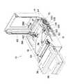
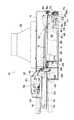
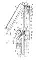
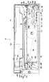
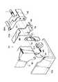
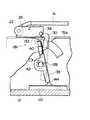
図1乃至図3には、本発明の実施の形態に係る画像記録装置10の全体構成が斜視図にて示されており、図4乃至図7には画像記録装置10の全体構成が側方から視た断面図にて示されている。また、図8には画像記録装置10の主要部の構成が側方から視た断面図にて示されている。
【0029】
画像記録装置10は、基台12及び上カバー14によって全体として箱形に形成されている。上カバー14は、その一端側(図4乃至図8紙面右端側)が、後に詳述するヒンジ部70によって基台12に連結支持されており、基台12に対し開閉移動可能となっている。また、基台12及び上カバー14の他端側(ヒンジ部70と反対側)には、同様に後述するロック部146が設けられており、通常は上カバー14を閉止状態で保持している。
【0030】
一方、基台12の内部中央には、ステージ16が設けられている。ステージ16は、平板状のヒート(加熱)盤で、その一端部(ヒンジ部70の側)は支軸18によって回動可能に支持されている。ステージ16には、支軸18と同軸的に持上げギヤ20が一体的に取り付けられており、持上げギヤ20を回転させることによりステージ16を支軸18周りに回動させる(他端側を持ち上げる)ことができる。また、ステージ16の他端部には、フリーローラ22が取り付けられている。このステージ16は、後に詳述するヒンジ部70に駆動機構を介して接続されており、ヒンジ部70の開閉移動に応じて支軸18周りに回動する。さらに、ステージ16の他端部に対応する基台12には、同様に後述するステージロック部126が設けられており、通常はステージ16の他端部を水平状態で保持している。
【0031】
また、基台12内には、ステージ16の一端側(ヒンジ部70の側)下方に供給マガジン24が設けられており、この供給マガジン24には、画像記録材料としての感光材料26がロール状に巻き取られて収容されている。感光材料26は、支持体上に感光性ハロゲン化銀、バインダー、色素供与性物質、還元剤を有して構成され、供給マガジン24からステージ16上に引き出されてステージ16上に水平に保持された状態では、感光面が上を向くようにされる。
【0032】
供給マガジン24とステージ16との間には、一対の引き出しローラ28A、28Bが配置されている。引き出しローラ28A、28Bはニップローラとされており、供給マガジン24から感光材料26を引き出すことができる。なお、この引き出しローラ28A、28Bのうち上側に位置する引き出しローラ28Aは、後述するヒンジ部70に連動してニップ解除方向へ移動可能である。
【0033】
また、ステージ16の下方には、上記供給マガジン24と近接して巻取マガジン30が設けられている。巻取マガジン30には、供給マガジン24から引き出されてステージ16を一端から他端(フリーローラ22)へ掛け渡された感光材料26が巻き取られている。この感光材料26は、所定長さ毎にステージ16上に引き出される。
【0034】
一方、基台12の上部には、ステージ16に対向して露光ユニット32が設けられている(なお、図4及び図5にのみ示してあり、他の図では図示を省略している)。露光ユニット32は、光源(図示省略)を備えており、原稿へ照射された照射光が、ステージ16上に位置する感光材料26に露光されるようになっている。なお、光源を原稿に沿って移動させながら、原稿の画像を感光材料26に順次に走査露光するように構成してもよい。
【0035】
また、画像記録装置10は、貼合せユニット34、給紙部36、及び水塗布部38を備えている。
【0036】
貼合せユニット34は、無端ベルト40が貼合せローラ42、及び複数の巻掛けローラ44に掛け渡されている。この貼合せユニット34は、待機位置(図4及び図5に示す如く基台12の左側端部位置)からステージ16の先端部(図4及び図5の右側端部)へ向けてステージ16上を順次移動できるようになっており、貼合せユニット34の前進に伴い、無端ベルト40がステージ16上を貼合せユニット34の前進に対応して走行する(図4及び図5で時計回りに走行する)。
【0037】
給紙部36は、待機位置にある貼合せユニット34の直上(図4及び図5に示す如く基台12の左側端部)に設けられている。この給紙部36には受材マガジン46が装填されており、さらに、受材マガジン46内には受像材料48が所定長さに切断されて重ねられてステージ16と平行に収容されている。受像材料48の一方の面には媒染剤を有する色素固定材料が塗布されて画像形成面とされており、受像材料48はこの画像形成面が上を向く状態で受材マガジン46内に収納されている。
【0038】
また、給紙部36には、受材マガジン46の先端部上方に吸着盤50が設けられると共に、待機位置にある貼合せユニット34の貼合せローラ42に対応して案内部52が設けられている。
【0039】
貼合せユニット34(無端ベルト40)の走行に伴い、受材マガジン46内にある受像材料48は吸着盤50によって吸着されて取り出され、案内部52を介して待機位置にある貼合せユニット34の貼合せローラ42(無端ベルト40の外周)へと送り込まれる構成である。さらに、待機位置にある貼合せユニット34の貼合せローラ42(無端ベルト40の外周)へと送り込まれた受像材料48は、無端ベルト40と共に移動することで反転し、その引き出し端が感光材料26と当接し、そして、貼合せユニット34の移動に伴い、受像材料48が無端ベルト40と感光材料26との間に挟持されるようにして、受像材料48が感光材料26と順次重ね合わされる構成である。
【0040】
一方、水塗布部38は、タンク54を備えている。このタンク54は、長尺な矩形箱状とされ、ステージ16の幅方向(図4及び図5の紙面手前・奥側方向)に沿って配されると共に、支持アーム56によって前述した貼合せユニット34に上下移動可能に支持されている。このため、タンク54は貼合せユニット34と共にステージ16に沿って順次移動するようになっている。タンク54内には、水等の転写助剤(画像形成用溶媒)が封入される。また、タンク54の底部にはスポンジ58が取り付けられている。スポンジ58は、タンク54内の水を吸収保持できる。
【0041】
また、水塗布部38には、ガイドホイール60が設けられている。ガイドホイール60は、基台12(上カバー14)に設けられた段差付きのガイドレール62に対応しており、ガイドレール62に沿って移動する。このガイドホイール60がガイドレール62に沿って移動することにより、タンク54が上下方向に案内され、タンク54の昇降に伴いスポンジ58も昇降する構成である。
【0042】
なお、タンク54の上昇位置ではスポンジ58がステージ16上の感光材料26から離間し、タンク54の降下位置ではステージ16上の感光材料26にスポンジ58が接触するように各部の寸法等が設定されている。スポンジ58が感光材料26へ押し付けられて接触した状態では、スポンジ58は圧縮されてスポンジ58から水が感光材料26へ流出し、さらにこの状態で水塗布部38(スポンジ58)が前進することにより、感光材料26に水が順次に塗布される構成である。
【0043】
さらに、タンク54の後方側(ガイドホイール60と反対側)には、スクイズローラ64が配置されている。スクイズローラ64は、タンク54(スポンジ58)と共に移動し、感光材料26に塗布された余分な水を除去することができる。
【0044】
感光材料26に原稿の画像が露光された後に、上記給紙部36による受像材料48の供給、水塗布部38による感光材料26への水塗布、及び、貼合せユニット34による受像材料48と感光材料26の貼り合わせがなされ、そして、受像材料48と感光材料26とが重ね合わされた状態でステージ16上で熱現像転写が行われる。すなわち、感光材料26の可動性の色素が放出され、同時に色素が受像材料48の色素固定層に転写されて、受像材料48に画像が得られる構成である。
【0045】
ここで、前述した上カバー14を基台12に開閉移動可能に連結支持するヒンジ部70及びロック部146について詳述する。
【0046】
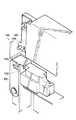
図9にはヒンジ部70の一部破断すると共に透視した斜視図が示されており、図10にはヒンジ部70の各構成部品を分解した斜視図が示されている。また、図11乃至図13にはこのヒンジ部70の構成が側方から視た断面図にて示されている。
【0047】
ヒンジ部70では、基台12の一部を構成する基板72Bが基板72Aに一体的に固着されており、さらに、基板72Bには中間ヒンジ74が取り付けられている。中間ヒンジ74はその一端部が、基板72Bから突出する支軸76によって回動自在に支持されている。一方、中間ヒンジ74の他端部には、支軸78によって前述した上カバー14が回動自在に支持されている。このように、上カバー14は、中間ヒンジ74を介して基台12(基板72A及び基板72B)に支持された構成である。
【0048】
中間ヒンジ74の装置外側面には、補助カバー80が取り付けられており、基台12の側面を被覆している。この補助カバー80は、常に中間ヒンジ74と一体に回動する。
【0049】
上カバー14の角部には、爪部82が形成されている。爪部82は、上カバー14が支軸78周りに回動した際に、基板72Bに形成された係合孔84に嵌入可能であり、爪部82が係合孔84内に嵌入した状態では、中間ヒンジ74の支軸76を中心とする回動が阻止される。すなわち、図11に示す如く上カバー14の閉鎖状態では、爪部82が係合孔84内に嵌入しており、この爪部82が係合孔84内に嵌入し中間ヒンジ74の支軸76を中心とする回動が阻止され上カバー14のみが支軸78周りに回動できる状態が、1段階目の開閉状態とされている(図11及び図12図示状態)。さらに、上カバー14の開放移動が進行して爪部82が係合孔84から抜け出して以後には、中間ヒンジ74の支軸76を中心とする回動が可能になり、この状態が2段階目の開閉状態とされている。
【0050】
また、上カバー14の開放移動が進行して爪部82が係合孔84から抜け出した時点で、上カバー14の背面先端に設けられたスライド係止部86が、補助カバー80の上端部に係合して、上カバー14のそれ以上の回動が阻止される構成である。
【0051】
また、上カバー14には、爪部82の近傍に、爪部88が形成されている。爪部88は、先端が円弧状に形成されており、基板72Aに設けられた係合凸部90に係合可能である。すなわち、爪部82が係合孔84内に嵌入し中間ヒンジ74の支軸76を中心とする回動が阻止され上カバー14のみが支軸78周りに回動できる状態(1段階目の開閉状態)においては、爪部88は係合凸部90から離間しており、さらに、上カバー14が支軸78周りに回動し爪部82が係合孔84から抜け出した後に(すなわち、2段階目の開閉状態となった際には)、爪部88は係合凸部90に沿って移動する。これにより、2段階目の開閉状態においては、前述の如く爪部82が係合孔84から抜け出し中間ヒンジ74の支軸76を中心とする回動が可能になると共に、上カバー14の支軸78を中心とする回動が阻止される構成である。したがって、この2段階目の開閉状態においては、上カバー14は中間ヒンジ74と一体的に、支軸76を中心として回動する。
【0052】
なお、本実施の形態においては、上カバー14の閉鎖状態から爪部82が係合孔84から抜け出すまでの間(すなわち、1段階目の開閉状態)が30度であり、その後に上カバー14が中間ヒンジ74と共に全開となるまでの間(2段階目の開閉状態)が60度となるように、各部の寸法等が設定されている。
【0053】
中間ヒンジ74の中央部(すなわち、中間ヒンジ74の回転中心としての支軸76から離間した位置)には、支軸92によって補助ブラケット94が回動自在に取り付けられている。補助ブラケット94は、側面視L字形に屈曲して形成されており、一端部にはU字形の切欠き部96が形成されている。この切欠き部96には、基板72Bから突出する固定ピン98が回動自在に入り込んでおり、これにより補助ブラケット94は、切欠き部96の側の端部の変移が阻止されている。
【0054】
補助ブラケット94の他端部(切欠き部96と反対側の端部)には、前述した引き出しローラ28Aが取り付けられている。この引き出しローラ28Aは、上カバー14及び中間ヒンジ74の閉鎖状態においては、前述した如く供給マガジン24から引き出された感光材料26を挟持しているが、中間ヒンジ74の支軸76を中心とする回動に伴って補助ブラケット94が回動することにより、一方の引き出しローラ28Bから離間して感光材料26の挟持を解除する構成である。
【0055】
さらにこの場合、補助ブラケット94の支持位置(すなわち、支軸92)は、中間ヒンジ74の一端回転中心(支軸76)から離間した位置とされており、かつ、補助ブラケット94は自身の一端部(切欠き部96の側の端部)の変移が阻止されているため、中間ヒンジ74の回動に伴って補助ブラケット94が回動する際には、補助ブラケット94の他端部(すなわち、引き出しローラ28A)は、中間ヒンジ74の回動角度よりも大きい角度で回動する。なお、本実施の形態においては、中間ヒンジ74が60度回動した時点(すなわち、上カバー14の全開状態)において、引き出しローラ28Aは初期位置から90度回動するように各部の寸法等が設定されている。
【0056】
またさらに、中間ヒンジ74には、連動手段を構成するギヤ100が取り付けられている。このギヤ100は支軸76と同軸的に固定されており、したがって、中間ヒンジ74の回動に連動する。
【0057】
ギヤ100には、基板72Aに取り付けられ同様に連動手段を構成する中間ギヤ102が噛み合っており、このため、中間ヒンジ74が回動すると、これに伴って中間ギヤ102が回転される。この中間ギヤ102は、前述した供給マガジン24のホルダ104に連結されている。図14に示す如く、中間ギヤ102には送り螺子106が一体に固定連結されており、さらに、送り螺子106には自身の回転が阻止されたホルダ104が螺合している。すなわち、中間ギヤ102が回転すると、ホルダ104が送り螺子106に沿って軸線方向に移動する構成である。このホルダ104は、円錐台形に形成されており、供給マガジン24の軸線方向端部に係合してこれを保持することができると共に、軸線方向(中間ギヤ102に接近する方向)に移動することで前記保持を解除することができる。これにより、供給マガジン24のセット及び交換が可能になる構成である。
【0058】
また、中間ギヤ102には、基板72Aに取り付けられ連動手段を構成する中間ギヤ108が噛み合っており、さらに、中間ギヤ108には、同様に連動手段を構成するスライドレバー110の第1ラック112が噛み合っている。したがって、中間ヒンジ74が回動すると、これに伴ってスライドレバー110が軸線方向にスライドされる構成である。
【0059】
スライドレバー110の第1ラック112の近傍には、第2ラック114が形成されている。この第2ラック114には、基板72Aに取り付けられ連動手段を構成する中間ギヤ116、118が順次噛み合っており、さらに、中間ギヤ118は、前述したステージ16の持上げギヤ20に噛み合っている。このため、スライドレバー110が移動すると、持上げギヤ20へ駆動力が伝達されて持上げギヤ20すなわちステージ16が支軸18周りに回動し先端部(フリーローラ22の側)が持ち上げられる構成である。
【0060】
なお、本実施の形態においては、スライドレバー110が全量移動した状態(換言すれば、中間ヒンジ74が60度回動した状態)で、すなわち上カバー14が全開した状態で、ステージ16が60度持ち上げられるようにギヤ比や各部の寸法等が設定されている。
【0061】
また、スライドレバー110は、基板72Aに沿って配設され、その長手方向中間部には引出しアーム120が取り付けられている。図15に示す如く、引出しアーム120の先端部はU字形に形成されており、カム122に係合可能である。図16及び図17にも示す如く、カム122は円錐台形に形成されており、前述した巻取マガジン30を保持するホルダ124に連結されている。すなわち、スライドレバー110が移動すると、引出しアーム120がカム122を押圧し、このカム122と共にホルダ124が軸線方向に移動する構成である。これにより、巻取マガジン30の交換が可能になる構成である。
【0062】
基板72Aに沿って配設されたスライドレバー110の先端は、前述したステージ16のステージロック部126に達している。
【0063】
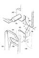
ここで、図18にはステージロック部126の詳細が斜視図にて示されている。また、図19乃至図22にはステージロック部126の詳細が側面図にて示されている。
【0064】
ステージロック部126では、基台12の一部を構成する基板72A及び基板72Bが一体的に固着されており、さらに、これらの基板72A及び基板72Bには、支軸128が貫通されている。この支軸128には、基板72Bの側にフックレバー130が支持されている。フックレバー130の上端部には爪132が形成されており、ステージ16の他端部に設けられたロックピン134に係合または離脱可能である。フックレバー130の爪132がロックピン134に係合した状態では、ステージ16が水平状態で保持される。
【0065】
フックレバー130には、支軸128に巻装されたリターンスプリング136の一端が係止されており、常にフックレバー130を爪132がロックピン134に係合する方向へ付勢している。
【0066】
また支軸128には、基板72Aの側に作動レバー138が支持されている。作動レバー138の上端部には、フックレバー130へ向けて腕部140が延出されており、フックレバー130のロックピン134の側の側面を押圧可能である。これにより、作動レバー138が支軸128周りに回動することで、腕部140がフックレバー130を押圧し、フックレバー130がリターンスプリング136の付勢力に抗してロックピン134から離間する(ロック解除)方向へ回動される構成である。
【0067】
作動レバー138には、支軸128に巻装されたリターンスプリング142の一端が係止されており、常に腕部140がフックレバー130を押圧する方向(したがって、リターンスプリング136の付勢方向と反対向き)へ付勢している。
【0068】
なおこの場合、リターンスプリング142の付勢力はリターンスプリング136の付勢力よりも弱く設定されている。したがって、通常は作動レバー138の腕部140はフックレバー130に圧接している。
【0069】
この作動レバー138の下端部は、基板72Aに沿って配置されたスライドレバー110の先端に対応しており、スライドレバー110の押圧突起144に係合可能である。すなわち、スライドレバー110が軸線方向に移動することで、押圧突起144が作動レバー138を押圧してリターンスプリング136の付勢力に抗して支軸128周りに回転させることができる構成である。
【0070】
なお、前記フックレバー130がロックピン134から離間(ロック解除)した後に持上げギヤ20へ駆動力が伝達され始め、スライドレバー110の押圧突起144が作動レバー138を押圧し続けている間(フックレバー130がロックピン134から離間している間)にステージ16の先端部が持ち上げられ、さらに、ステージ16が完全に(60度)持ち上がった後にスライドレバー110の押圧突起144が作動レバー138から外れて作動レバー138が自動復帰するタイミングとなるように、各部の寸法等が設定されている。
【0071】
以上の如き構成によって開閉する上カバー14は、ロック部146によって基台12に保持されている。ここで、図23及び図24にはこのロック部146の詳細が斜視図にて示されている。
【0072】
ロック部146では、一対のラッチ板148、150が設けられている。ラッチ板148、150は先端部がY字形に形成されており、互いのY字形部分が対向しかつ直交するようにして、一方のラッチ板148が上カバー14に固定される共に他方のラッチ板150が基台12(基板72A)に固定されている。これにより、ラッチ板148のY字形部分とラッチ板150のY字形部分とが互いに嵌まり合うことで、上カバー14の基台12に対する位置決めが行われる構成である。
【0073】
また、基台12に固定されたラッチ板150の近傍には、ロックレバー152が取り付けられている。ロックレバー152の上端部にはロック爪154が形成されている。このロック爪154は、上カバー14に固定されたラッチ板148に設けられたロックピン156に対応しており、上カバー14が閉鎖されラッチ板148のY字形部分とラッチ板150のY字形部分とが互いに嵌まり合った状態で、ロック爪154がロックピン156に係合するようになっている。ロックレバー152のロック爪154がロックピン156に係合した状態では、上カバー14が閉鎖状態で保持される。
【0074】
また、ロックレバー152の回転軸には開閉ノブ158(図3、図5乃至図7を参照)が取り付けられており、この開閉ノブ158を操作することでロックレバー152を回動させて上カバー14を開放移動させることができる。
【0075】
次に、本実施の形態の作用を説明する。
上記構成の画像記録装置10では、感光材料26が供給マガジン24からステージ16上に所定長さ引き出される。ステージ16上に位置する感光材料26には、露光ユニット32によって原稿の画像が露光される。
【0076】
次いで、受材マガジン46内にある受像材料48が吸着盤50によって吸着されて取り出され、案内部52を介して待機位置にある貼合せユニット34の貼合せローラ42(無端ベルト40の外周)へと送り込まれる。さらに、貼合せユニット34が移動し、送り込まれた受像材料48が無端ベルト40と共に移動することで反転し、受像材料48が無端ベルト40と感光材料26との間に挟持されるようにして、受像材料48が感光材料26と順次重ね合わされる。
【0077】
さらにこの際、受像材料48と感光材料26の重ね合わせに先立って、貼合せユニット34と共に移動する水塗布部38のスポンジ58によって、感光材料26に水が順次に塗布されると共に、スクイズローラ64によって余分な水が感光材料26から除去される。
【0078】
これにより、受像材料48は、水が塗布されたステージ16上に位置する感光材料26に、順次貼り合わされる。
【0079】
ステージ16上で互いに貼り合わされた受像材料48と感光材料26は、重ね合わされた状態でステージ16によって加熱され、これにより熱現像転写が行われる。すなわち、感光材料26の可動性の色素が放出され、同時に色素が受像材料48の色素固定層に転写されて、受像材料48に画像が得られる。
【0080】
熱現像転写が行われた後には、貼合せユニット34が前述とは逆向きに初期位置へと移動する。この貼合せユニット34の後退により、感光材料26が所定長さ分だけ引き出されると共に、受像材料48は、感光材料26と共にステージ16の他端からステージ外へ移動されながら、その移動に伴い感光材料26と剥離されて、排出トレイ160内に集積される。
【0081】
その後は、貼合せユニット34、水塗布部38、及び給紙部36は待機状態となって、次回の処理に備える。
【0082】
ここで、本実施の形態に係る画像記録装置10では、上カバー14を基台12に対し開放することができる。すなわち、開閉ノブ158を操作することでロックレバー152を回動させる。これにより、ロックレバー152のロック爪154が上カバー14に固定されたラッチ板148のロックピン156から離脱して、上カバー14の閉鎖保持状態が解除され、上カバー14を開放移動させることができる。
【0083】
またこの場合、ヒンジ部70の中間ヒンジ74によって基台12に対し連結された上カバー14は、所定角度(30度及び90度)で2段階の開閉状態にすることができる。
【0084】
この場合、上カバー14の1段階目の開閉状態(閉鎖状態から30度の開放状態までの間)においては、中間ヒンジ74の支軸78(すなわち、上カバー14との連結側)を中心として上カバー14が開閉移動する。これにより、図6に示す如く、装置本体内(基台12内)上部に位置する水塗布部38等が露出される。したがって、例えばタンク54内の水の補充等の点検整備作業を容易に実施することができる。
【0085】
一方、上カバー14の2段階目の開閉状態(30度の開放状態から90度の全開放状態までの間)においては、中間ヒンジ74の支軸76(すなわち、基台12への連結側)を中心として上カバー14が中間ヒンジ74と共に開閉移動する。これにより、図1乃至図3、及び図7に示す如く装置本体(基台12)内部が更に大きく露出される。
【0086】
特にこの2段階目の開放時には、1段階目の開放時における上カバー14の回動中心(すなわち、中間ヒンジ74の支軸78)とは異なる位置(すなわち、中間ヒンジ74の支軸76)を回動中心として上カバー14が回動するため、前記各回動中心が離間していることに起因して、上カバー14は中間ヒンジ74自体の回動角度よりも更に大きく回動する。したがって、装置本体(基台12)内部が大きく露出される。
【0087】
またここで、この画像記録装置10では、中間ヒンジ74の中央部(すなわち、中間ヒンジ74の回転中心としての支軸76から離間した位置)には、支軸92によって補助ブラケット94が回動自在に取り付けられているため、中間ヒンジ74の回動の際に、すなわち2段階目の開閉状態において中間ヒンジ74の回動に伴って補助ブラケット94が自動的に回動される。
この場合、補助ブラケット94の支持位置(すなわち、支軸92)は、中間ヒンジ74の一端回転中心(支軸76)から離間した位置とされており、かつ、補助ブラケット94は自身の一端部(切欠き部96の側の端部)の変移が固定ピン98によって阻止されているため、中間ヒンジ74の回動に伴って補助ブラケット94が回動する際には、補助ブラケット94の他端部(すなわち、引き出しローラ28A)は、中間ヒンジ74の回動角度よりも大きい角度で回動する。本実施の形態においては、中間ヒンジ74が60度回動した時点で(すなわち、上カバー14の全開状態)においては、引き出しローラ28Aは初期位置から90度回動する。これにより、図13に示す如く、引き出しローラ28Aが他方の引き出しローラ28Bから離間して感光材料26の挟持を解除するのみならず、この引き出しローラ28Aが基台12内から大きく退避され、点検整備等の作業性が向上する。
【0088】
さらにここで、中間ヒンジ74が回動する際には(すなわち、2段階目の開放時には)、自動的にステージ16が上昇される。
【0089】
すなわち、中間ヒンジ74が回動する際には、これに伴ってスライドレバー110が移動される。このスライドレバー110の移動により、ステージロック部126の作動レバー138がスライドレバー110の押圧突起144に押圧されて、リターンスプリング136の付勢力に抗して支軸128周りに回転される。これにより、図20に示す如く、作動レバー138の腕部140がフックレバー130を押圧し、フックレバー130がリターンスプリング136の付勢力に抗してロックピン134から離間する(ロック解除)方向へ回動され、フックレバー130の爪132がロックピン134から離脱してステージ16の保持が解除される。
【0090】
さらにこの時点で、スライドレバー110の移動力が持上げギヤ20へ伝達され始め、スライドレバー110の押圧突起144が作動レバー138を押圧し続けている間(フックレバー130がロックピン134から離間している間)にステージ16の先端部が持ち上げられる。
【0091】
さらに、ステージ16が完全に(60度)持ち上がった後には、図21に示す如くスライドレバー110の押圧突起144が作動レバー138から外れて作動レバー138及びフックレバー130が自動復帰する。
【0092】
なお、スライドレバー110の押圧突起144が作動レバー138から外れた後にスライドレバー110が前述とは逆向きに復帰移動する際には(換言すれば、上カバー14が閉鎖される際には)、前述とは逆方向から押圧突起144が作動レバー138を押圧する。これにより、図22に示す如く、作動レバー138のみがリターンスプリング142の付勢力に抗して前述とは逆向きにフックレバー130から離間する方向へ一旦回転され、再びスライドレバー110の押圧突起144が作動レバー138から外れて完全に元の状態に復帰する。
【0093】
またさらに、このようにステージ16の先端部が持ち上げられる際には(中間ヒンジ74が回動する際には)、これに伴って中間ギヤ102が回転されて、図14に二点鎖線にて示す如く、ホルダ104が送り螺子106に沿って軸線方向に移動される。これにより、供給マガジン24の保持が解除される。これと同様に、中間ヒンジ74が回動しスライドレバー110が移動すると、引出しアーム120がカム122を押圧し、図17に示す如くこのカム122と共にホルダ124が軸線方向に移動される。これにより、巻取マガジン30の保持が解除される。
【0094】
以上の如く、上カバー14の2段階目の開放時には、装置本体(基台12)内部が大きく露出されるのみならず、引き出しローラ28Aが上カバー14と共に移動して基台12内から大きく退避され、さらに、自動的にステージ16が上昇されると共に、供給マガジン24及び巻取マガジン30の保持が解除される。したがって、供給マガジン24や巻取マガジン30の交換等の点検整備作業を容易に実施することができる。
【0095】
なお、供給マガジン24及び巻取マガジン30を一体となし、ステージ16を跨いで両者を同時に着脱する構成も可能である。
【0096】
またさらに、画像記録装置10では、上カバー14の1段階目の開閉状態においては、爪部82によって、中間ヒンジ74の支軸76(すなわち、基台12への連結側)を中心とする中間ヒンジ74の回動が制限されている。これにより、中間ヒンジ74の支軸78(すなわち、上カバー14との連結側)を中心とする上カバー14の開閉移動のみが可能である。すなわち、上カバー14が完全に1段階目の開放状態となった後でなければ(閉鎖状態から30度の開放状態への移動が終了した後でなければ)、中間ヒンジ74は支軸76(すなわち、基台12への連結側)を中心とした回動ができず、中間ヒンジ74が不要に2段階目の開閉状態へ移行することがない。
【0097】
一方、上カバー14が1段階目の開閉状態(30度の開放状態)とされた後に、上カバー14及び中間ヒンジ74が2段階目の開閉状態となった際には、爪部88と係合凸部90との係合作用、及び、スライド係止部86と補助カバー80との係合作用によって、中間ヒンジ74の支軸78(すなわち、上カバー14との連結側)を中心とする上カバー14の回動が制限される(図13図示状態)。これにより、中間ヒンジ74の支軸76(すなわち、基台12への連結側)を中心とする中間ヒンジ74及び上カバー14の開閉移動のみが可能である。すなわち、2段階目の開閉状態にある上カバー14が中間ヒンジ74と共に完全に1段階目の開閉状態へと移行した後でなければ(2段階目から1段階目への閉鎖移動が終了した後でなければ)、上カバー14は中間ヒンジ74の支軸78(すなわち、上カバー14との連結側)を中心とした回動ができず、2段階目の開閉状態にある上カバー14が不要に回動することがない。
【0098】
このように、上カバー14が1段階目の開放移動を終了してからでないと中間ヒンジ74は回動できず、一方、中間ヒンジ74が2段階目から1段階目への閉鎖移動を終了した後でなければ上カバー14は回動できない。
【0099】
したがって、1段階目の開閉状態と2段階目の開閉状態とを、確実に順次規則的に行うことができ、操作性が向上する。
【0100】
一方、前述の如く開放された上カバー14を閉鎖する場合には、ロック部146においてロックレバー152のロック爪154がラッチ板148のロックピン156に係合して、上カバー14が閉鎖状態で保持される。
【0101】
この場合、上カバー14に固定されたラッチ板148のY字形部分と、基台12(基板72A)に固定されたラッチ板150のY字形部分とが互いに嵌まり合うことで、上カバー14の基台12に対する位置決めが行われる。
【0102】
すなわち、図24に示す如く、ヒンジ部70(中間ヒンジ74)によって基台12に連結支持された上カバー14は、基台12に対する装置前後方向(図4乃至図8の紙面左右方向)の位置が、ラッチ板148のY字形部分の切欠隙間寸法Aと、これに嵌入するラッチ板150のY字形部分の板厚寸法tによって、一義的に決定される。一方、上カバー14の基台12に対する装置高さ方向の位置は、ラッチ板148のY字形部分の切欠深さ位置B1と、これに嵌入するラッチ板150のY字形部分の切欠深さ位置B2によって(換言すれば、ラッチ板148のY字形部分とラッチ板150のY字形部分の突き合わせ位置によって)、一義的に決定される。またさらに、上カバー14の基台12に対する装置左右方向の位置は、ラッチ板150のY字形部分の切欠隙間寸法Cと、これに嵌入するラッチ板148のY字形部分の板厚寸法tによって、一義的に決定される。
【0103】
したがって、上カバー14に固定されたラッチ板148のY字形部分と、基台12に固定されたラッチ板150のY字形部分とを精度良く製造組付けすれば、上カバー14を基台12に対して高精度に位置決めすることができる。
【0104】
またこのため、上カバー14を中間ヒンジ74によって基台12に連結支持するこれらの連結部分の剛性を、不要に高くする必要がなくなる。
【0105】
以上の如く、本実施の形態に係る画像記録装置10では、簡単な操作で必要な箇所を好適に露出させることができ、点検整備等の作業性が向上する。
【0106】
なお、本実施の形態に係る画像記録装置10に適用できる感光材料26としては、像様露光して得られる潜像を水等の画像形成用溶媒の存在のもとに受像材料48へ熱現像転写して可視像を得る、いわゆる熱現像感光材料が挙げられる。この熱現像感光材料は、基本的には支持体上に感光性ハロゲン化銀、還元剤、バインダー及び色素供与性化合物(還元剤が兼ねる場合もある)を有するものであり、更に必要に応じて有機金属塩酸化剤等を含有させることができる。
【0107】
熱現像感光材料は露光に対してネガの画像を与えるものでも、ポジの画像を与えるものでもよい。ポジの画像を与える方式には、ハロゲン化銀乳剤として直接ポジ乳剤(造核剤を用いる方式、光かぶらせ方式の2種がある)を用いる方式、ポジ状に拡散性の色素像を放出する色素供与性化合物を用いる方式のいずれもが採用できる。
【0108】
ポジの画像を与える方式の熱現像感光材料としては、例えば、特開平6−161070号公報、特開平6−289555号公報等に記載されたものが、また、ネガの画像を与える方式の熱現像感光材料としては、例えば、特開平5−181246号公報、特開平6−242546号公報等に記載されたものを用いることができる。
【0109】
また、画像形成用溶媒としては、例えば水があり、この水は、いわゆる純水に限らず、広く一般的に使用されている意味での水を含む。また、純水とメタノール、DMF、アセトン、ジイソブチルケトン等の低沸点溶媒との混合溶媒でもよい。更に、画像形成促進剤、カブリ防止剤、現像停止剤、親水性熱溶剤等を含有させた溶液でもよい。
【0110】
【発明の効果】
以上に説明した如く、本発明に係る画像記録装置は、簡単な操作で必要な箇所を好適に露出させることができ、点検整備等の作業性が向上するという優れた効果を有している。
【図面の簡単な説明】
【図1】本発明の実施の形態に係る画像記録装置の全体構成を示し、上カバーを全開放した状態の斜視図である。
【図2】本発明の実施の形態に係る画像記録装置の全体構成を示し、上カバーを全開放した状態の斜視図である。
【図3】本発明の実施の形態に係る画像記録装置の全体構成を示し、上カバーを全開放した状態の斜視図である。
【図4】本発明の実施の形態に係る画像記録装置の全体構成を示す側方から視た断面図である。
【図5】本発明の実施の形態に係る画像記録装置の全体構成を示す側方から視た断面図である。
【図6】本発明の実施の形態に係る画像記録装置の全体構成を示し、上カバーを1段階開放した状態の側方から視た断面図である。
【図7】本発明の実施の形態に係る画像記録装置の全体構成を示し、上カバーを全開放した状態の側方から視た断面図である。
【図8】本発明の実施の形態に係る画像記録装置のヒンジ部、ステージ、ステージロック部等の対応関係を示す側方から視た断面図である。
【図9】本発明の実施の形態に係る画像記録装置のヒンジ部の一部破断すると共に透視した斜視図である。
【図10】本発明の実施の形態に係る画像記録装置のヒンジ部の各構成部品を分解して示す斜視図である。
【図11】本発明の実施の形態に係る画像記録装置のヒンジ部の各構成部品を示し、上カバーの閉鎖状態における側方から視た断面図である。
【図12】本発明の実施の形態に係る画像記録装置のヒンジ部の各構成部品を示し、上カバーが1段階開放した状態における側方から視た断面図である。
【図13】本発明の実施の形態に係る画像記録装置のヒンジ部の各構成部品を示し、上カバーが全開放した状態における側方から視た断面図である。
【図14】本発明の実施の形態に係る画像記録装置の供給マガジンの保持解除機構を示す斜視図である。
【図15】本発明の実施の形態に係る画像記録装置の供給マガジンの保持解除機構を示す側面図である。
【図16】本発明の実施の形態に係る画像記録装置の供給マガジンの保持解除機構を示す平面図である。
【図17】本発明の実施の形態に係る画像記録装置の供給マガジンの保持解除機構を示し、解除状態における平面図である。
【図18】本発明の実施の形態に係る画像記録装置のステージロック部の構成を示す斜視図である。
【図19】本発明の実施の形態に係る画像記録装置のステージロック部の構成を示す側面図である。
【図20】本発明の実施の形態に係る画像記録装置のステージロック部の構成を示す側面図である。
【図21】本発明の実施の形態に係る画像記録装置のステージロック部の構成を示す側面図である。
【図22】本発明の実施の形態に係る画像記録装置のステージロック部の構成を示す側面図である。
【図23】本発明の実施の形態に係る画像記録装置のロック部の構成を示す斜視図である。
【図24】本発明の実施の形態に係る画像記録装置のロック部のラッチ板の構成を示す斜視図である。
【符号の説明】
10 画像記録装置
12 基台
14 上カバー
16 ステージ(可動部品)
20 持上げギヤ(連動手段)
24 供給マガジン(感材マガジン)
26 感光材料
30 巻取マガジン(感材マガジン)
34 貼合せユニット
36 給紙部
38 水塗布部
40 無端ベルト
42 貼合せローラ
46 受材マガジン
48 受像材料
54 タンク
70 ヒンジ部
74 中間ヒンジ(中間ヒンジ部材)
76 支軸
78 支軸
92 支軸
94 補助ブラケット(可動部品)
96 切欠き部
98 固定ピン
100 ギヤ(連動手段)
102 中間ギヤ(連動手段)
104 ホルダ(可動部品)
108 中間ギヤ(連動手段)
110 スライドレバー(連動手段)
112 第1ラック
114 第2ラック
116 中間ギヤ(連動手段)
118 中間ギヤ(連動手段)
120 引出しアーム(連動手段)
122 カム(連動手段)
124 ホルダ(可動部品)
126 ステージロック部
130 フックレバー
138 作動レバー[0001]
BACKGROUND OF THE INVENTION
The present invention relates to an image recording apparatus for obtaining a visible image by exposing a photosensitive material.
[0002]
[Prior art]
Some image recording apparatuses that obtain a color image on a sheet material expose an image of a document on a photosensitive material, and heat-develop and transfer the exposed photosensitive material on the image receiving material to obtain an image on the image receiving material.
[0003]
Among such image recording apparatuses, there is an apparatus provided with a flat processing stage in the apparatus. This type of processing stage is an exposure stage and a heating (heat) plate for holding the photosensitive material on a flat surface when exposing the image of the original to the photosensitive material. The photosensitive material is superposed on the image receiving material and then heated in a close contact state for thermal development transfer. Further, in an image recording apparatus provided with such a processing stage, a photosensitive material magazine for storing a photosensitive material is disposed below the processing stage. On the other hand, above the processing stage, there is a water application unit for applying water to the photosensitive material drawn from the photosensitive material magazine, a paper feeding unit for extracting and supplying the image receiving material from the receiving material magazine, or a supplied image receiving material. A laminating unit or the like is disposed on the processing stage so as to be in close contact with the photosensitive material. A configuration in which an image receiving material is superposed in close contact with a photosensitive material on the processing stage, heated in a close contact state, and subjected to heat development transfer processing by moving the laminating unit along the processing stage, and an image is obtained on the image receiving material. It is.
[0004]
By the way, in such an image recording apparatus, maintenance in the apparatus, for example, replenishment of water to the water application section (water tank), replacement of the photosensitive material magazine, or clogging processing of material (so-called jamming) is performed. Therefore, a structure that can open the inside of the apparatus is suitable.
[0005]
In this regard, simply providing inspection holes, inspection doors, etc. in the main body of the device allows for some maintenance, but places that are deep inside the device (for example, photosensitive material magazines located below the processing stage) It cannot be exposed and is therefore difficult to fully service.
[0006]
Also, in this case, providing a large cover on the main body of the apparatus and simply opening the cover greatly allows the inside of the apparatus to be exposed only (because the cover is removed). It is still difficult to facilitate inspection and maintenance of the recessed parts.
[0007]
[Problems to be solved by the invention]
In view of the above facts, an object of the present invention is to provide an image recording apparatus capable of suitably exposing a necessary portion with a simple operation and improving workability such as inspection and maintenance.
[0008]
[Means for Solving the Problems]
An image reading apparatus according to a first aspect of the present invention is an image recording apparatus in which a photosensitive material is exposed to obtain a visible image, wherein the apparatus main body is constituted by a base and an upper cover, and the upper cover is formed by a hinge portion. Linked to the base so that it can be opened and closed, and provided with interlocking means for driving the movable parts provided in the apparatus body in conjunction with the opening and closing operation of the upper cover.The hinge portion includes an intermediate hinge member having one end pivotably supported on the base and the other end pivotally connected to the upper cover so that the upper cover is opened and closed in two stages at a predetermined angle. The upper cover is opened / closed around the other end of the intermediate hinge member in the first stage opened / closed state, and the upper cover is moved around the one end of the intermediate hinge member in the second stage opened / closed state. The opening and closing movement together with the intermediate hinge member, the interlocking means drives the movable part in conjunction with rotation around one end of the intermediate hinge member in the second stage opening and closing state, the movable part, An auxiliary bracket that is rotatably supported by the intermediate hinge member at a position spaced from the rotation center of the one end of the intermediate hinge member and is prevented from shifting at its one end, and the auxiliary bracket A roller attached to the other end of the ket and rotating at an angle larger than the rotation angle of the intermediate hinge member as the intermediate hinge member rotates around the one end of the intermediate hinge member; TheIt is characterized by that.
[0009]
In the image recording apparatus according to the first aspect, when the upper cover connected to the base by the hinge portion is opened, the upper part of the apparatus main body (inside the base) is exposed. Further, when the upper cover is opened, the interlocking unit is activated in accordance with the opening / closing operation of the upper cover, and the movable part provided in the apparatus main body is driven.
[0010]
Therefore, if the moving direction of the movable part is set appropriately (for example, if it is set in a direction that largely protrudes from the inside of the apparatus main body (base)), the inside of the apparatus main body (base) automatically increases. Exposed. Thereby, a necessary part can be suitably exposed by a simple operation without complicated work, and workability such as inspection and maintenance is improved.
In addition, the upper cover is connected and supported to the base by the intermediate hinge member of the hinge portion, and can be opened and closed in two stages at a predetermined angle. Here, in the first-stage opening / closing state of the upper cover, the upper cover is opened / closed around the other end of the intermediate hinge member (that is, the connection side with the upper cover). Thereby, the upper part in the apparatus main body (inside the base) is exposed. On the other hand, in the second stage opening / closing state of the upper cover, the upper cover moves together with the intermediate hinge member around the one end of the intermediate hinge member (that is, the connection side to the base). As a result, the inside of the apparatus main body (base) is further exposed. Particularly when the second stage is opened, a position different from the rotation center of the upper cover (that is, the other end of the intermediate hinge member) at the time of opening the first stage (that is, one end of the intermediate hinge member) is used as the rotation center. Since the upper cover rotates, the upper cover rotates further than the rotation angle of the intermediate hinge member itself due to the separation of the respective rotation centers. Therefore, the inside of the apparatus main body (base) is greatly exposed.
Further, in the second-stage open / closed state, the interlocking unit is operated as the center hinge member is rotated around one end, and the movable part provided in the apparatus main body is driven.
Therefore, if each open state is properly used, only necessary portions can be exposed automatically and suitably, and workability such as inspection and maintenance is improved.
Further, since the auxiliary bracket as the movable part is rotatably supported by the intermediate hinge member, when the intermediate hinge member is rotated, that is, in the second stage opened / closed state, the intermediate hinge member is rotated. Automatically rotate.
Here, the supporting position of the auxiliary bracket is a position separated from the rotation center of one end of the intermediate hinge member, and the auxiliary bracket is prevented from shifting at its one end, so the rotation of the intermediate hinge member is prevented. Accordingly, when the auxiliary bracket rotates, the other end of the auxiliary bracket, that is, the roller attached thereto rotates at an angle larger than the rotation angle of the intermediate hinge member.
Therefore, the position of the roller in the second stage opened state of the upper cover and the intermediate hinge member is greatly different from the position of the roller in the closed state (in other words, the roller is moved from the inside of the apparatus in the second stage opened state). The workability of inspection and maintenance is improved.
[0019]
Claim2The image recording apparatus of the invention according to claim1In the image recording apparatus described above, the image recording apparatus is configured to obtain a visible image on the image receiving material by performing heat development transfer by superimposing the image receiving material on the photosensitive material after exposure to the photosensitive material, and the movable part. Is a stage in which one end is rotatably supported on the base and the photothermographic material and the image receiving material are superposed on each other with heat development transfer processing, and the interlocking unit raises and lowers the front end of the stage. It is characterized by that.
[0020]
Claim2In the image recording apparatus described above, when the intermediate hinge member is rotated, that is, in the second-stage opened / closed state, the interlocking unit is operated in accordance with the rotation of the intermediate hinge member, and the front end of the stage is automatically raised and lowered. Is done. Therefore, in the open state in the second stage, the tip of the stage can be lifted and retreated from the apparatus.
[0021]
As a result, it is possible to expose the recessed portion of the apparatus with a simple operation without complicated work, and workability such as inspection and maintenance is improved.
[0022]
Claim3The image recording apparatus of the invention according to claim2The image recording apparatus according to claim 1, further comprising a stage lock portion that engages with the other end portion of the stage and holds the stage in a horizontal state, wherein the interlocking unit is configured to move the intermediate hinge member in the second-stage open / close state. The stage lock portion is driven in conjunction with rotation about one end to release the holding state.
[0023]
Claim3In the image recording apparatus described above, in the second stage opened / closed state, that is, when the intermediate hinge member is rotated, the interlocking unit is operated to drive the stage lock portion, and the stage holding state is automatically released. The Therefore, it is possible to lift the stage with a simple operation and expose the recessed portion of the apparatus without complicated operations, and workability such as inspection and maintenance is improved.
[0024]
Claim4The image recording apparatus of the invention according to claim3In the image recording apparatus described above, the interlocking unit is characterized in that the timing is set so as to raise the other end of the stage after driving the stage lock unit to release the holding state. .
[0025]
Claim4In the described image recording apparatus, the interlocking unit operates by shifting the timing for driving the stage lock unit to release the holding state of the stage and the timing for raising the other end of the stage. Therefore, each of these operations can be performed as a continuous series of operations.
[0026]
Claim5The image recording apparatus of the invention according to claim1The image recording apparatus according to claim 1, further comprising a photosensitive material magazine that winds and houses the photosensitive material in a roll shape, wherein the movable part is a holder that holds the photosensitive material magazine, and the interlocking unit includes the holder. The photosensitive material magazine is driven in the holding release direction.
[0027]
Claim5In the described image recording apparatus, when the intermediate hinge member is rotated, that is, in the second-stage opened / closed state, the interlocking unit is operated in accordance with the rotation of the intermediate hinge member, and the holder for holding the photosensitive material magazine is the photosensitive material. It is automatically driven in the magazine holding release direction. Therefore, in the open state in the second stage, the photosensitive material magazine can be easily removed and replaced as it is, and workability such as inspection and maintenance is improved.
[0028]
DETAILED DESCRIPTION OF THE INVENTION
1 to 3 are perspective views showing the overall configuration of the
[0029]
The
[0030]
On the other hand, a
[0031]
Further, a
[0032]
Between the
[0033]
A take-up
[0034]
On the other hand, an
[0035]
Further, the
[0036]
In the
[0037]
The
[0038]
Further, the
[0039]
As the laminating unit 34 (endless belt 40) travels, the
[0040]
On the other hand, the
[0041]
The
[0042]
Note that the dimensions and the like of each part are set so that the
[0043]
Furthermore, a
[0044]
After the image of the document is exposed on the
[0045]
Here, the
[0046]
FIG. 9 is a perspective view of the
[0047]
In the
[0048]
An
[0049]
[0050]
Further, when the opening movement of the
[0051]
Further, a
[0052]
In the present embodiment, the period from when the
[0053]
An
[0054]
The
[0055]
Further, in this case, the support position of the auxiliary bracket 94 (that is, the support shaft 92) is a position separated from the one end rotation center (support shaft 76) of the
[0056]
Furthermore, the
[0057]
The
[0058]
Further, the
[0059]
A
[0060]
In the present embodiment, the
[0061]
The
[0062]
The tip of the
[0063]
Here, FIG. 18 is a perspective view showing details of the
[0064]
In the
[0065]
One end of a
[0066]
An
[0067]
One end of a
[0068]
In this case, the urging force of the
[0069]
The lower end portion of the
[0070]
The drive force starts to be transmitted to the
[0071]
The
[0072]
The
[0073]
A
[0074]
An opening / closing knob 158 (see FIGS. 3 and 5 to 7) is attached to the rotation shaft of the
[0075]
Next, the operation of the present embodiment will be described.
In the
[0076]
Next, the
[0077]
Further, at this time, prior to the superposition of the
[0078]
As a result, the
[0079]
The
[0080]
After the heat development transfer is performed, the
[0081]
Thereafter, the
[0082]
Here, in the
[0083]
In this case, the
[0084]
In this case, in the first-stage open / close state of the upper cover 14 (between the closed state and the open state of 30 degrees), the
[0085]
On the other hand, in the second-stage open / close state of the upper cover 14 (between the open state of 30 degrees and the fully open state of 90 degrees), the
[0086]
In particular, when the second stage is opened, a position different from the rotation center of the upper cover 14 (that is, the
[0087]
Further, in this
In this case, the support position of the auxiliary bracket 94 (that is, the support shaft 92) is a position separated from the one end rotation center (support shaft 76) of the
[0088]
Further, here, when the
[0089]
That is, when the
[0090]
Further, at this time, the moving force of the
[0091]
Further, after the
[0092]
When the
[0093]
Furthermore, when the front end of the
[0094]
As described above, when the
[0095]
It is also possible to adopt a configuration in which the
[0096]
Furthermore, in the
[0097]
On the other hand, when the
[0098]
Thus, the
[0099]
Therefore, the first-stage opening / closing state and the second-stage opening / closing state can be reliably and regularly performed, and the operability is improved.
[0100]
On the other hand, when the
[0101]
In this case, the Y-shaped portion of the
[0102]
That is, as shown in FIG. 24, the
[0103]
Therefore, if the Y-shaped part of the
[0104]
For this reason, it is not necessary to unnecessarily increase the rigidity of these connecting portions that connect and support the
[0105]
As described above, in the
[0106]
As the
[0107]
The photothermographic material may provide a negative image or a positive image upon exposure. There are two methods for giving positive images: one using a direct positive emulsion (two types: a nucleating agent method and a light fogging method) as a silver halide emulsion, and a positive diffusible dye image is emitted. Any method using a dye-donating compound can be employed.
[0108]
Examples of the photothermographic material that gives a positive image include those described in JP-A-6-161070, JP-A-6-289555, and the like, and a photothermographic material that gives a negative image. As the photosensitive material, for example, those described in JP-A-5-181246 and JP-A-6-242546 can be used.
[0109]
The image forming solvent includes, for example, water. This water is not limited to so-called pure water, but includes water in the sense that it is widely used. Moreover, a mixed solvent of pure water and a low boiling point solvent such as methanol, DMF, acetone, diisobutyl ketone, or the like may be used. Further, it may be a solution containing an image formation accelerator, an antifoggant, a development stopper, a hydrophilic thermal solvent, and the like.
[0110]
【The invention's effect】
As described above, the image recording apparatus according to the present invention has an excellent effect that a necessary portion can be suitably exposed by a simple operation, and workability such as inspection and maintenance is improved.
[Brief description of the drawings]
FIG. 1 is a perspective view showing an overall configuration of an image recording apparatus according to an embodiment of the present invention, with an upper cover fully opened.
FIG. 2 is a perspective view showing the entire configuration of the image recording apparatus according to the embodiment of the present invention, with the upper cover fully opened.
FIG. 3 is a perspective view showing the overall configuration of the image recording apparatus according to the embodiment of the present invention, with the upper cover fully opened.
FIG. 4 is a side sectional view showing the entire configuration of the image recording apparatus according to the embodiment of the present invention, viewed from the side.
FIG. 5 is a side sectional view showing the entire configuration of the image recording apparatus according to the embodiment of the present invention, viewed from the side.
FIG. 6 is a cross-sectional view showing the overall configuration of the image recording apparatus according to the embodiment of the present invention, viewed from the side with the upper cover opened in one stage.
FIG. 7 is a cross-sectional view showing the overall configuration of the image recording apparatus according to the embodiment of the present invention, viewed from the side with the upper cover fully opened.
FIG. 8 is a cross-sectional view seen from the side showing a correspondence relationship between a hinge portion, a stage, a stage lock portion, and the like of the image recording apparatus according to the embodiment of the present invention.
FIG. 9 is a perspective view in which the hinge portion of the image recording apparatus according to the embodiment of the present invention is partially broken and seen through.
FIG. 10 is an exploded perspective view showing components of a hinge part of the image recording apparatus according to the embodiment of the present invention.
FIG. 11 is a cross-sectional view showing each component of the hinge portion of the image recording apparatus according to the embodiment of the present invention, viewed from the side in the closed state of the upper cover.
FIG. 12 is a cross-sectional view showing each component of the hinge portion of the image recording apparatus according to the embodiment of the present invention, viewed from the side in a state where the upper cover is opened in one stage.
FIG. 13 is a cross-sectional view showing each component of the hinge portion of the image recording apparatus according to the embodiment of the present invention, viewed from the side in a state where the upper cover is fully opened.
FIG. 14 is a perspective view showing a holding release mechanism of the supply magazine of the image recording apparatus according to the embodiment of the present invention.
FIG. 15 is a side view showing the holding release mechanism of the supply magazine of the image recording apparatus according to the embodiment of the present invention.
FIG. 16 is a plan view showing a holding release mechanism of the supply magazine of the image recording apparatus according to the embodiment of the present invention.
FIG. 17 is a plan view of the supply magazine holding and releasing mechanism of the image recording apparatus according to the embodiment of the present invention in the released state;
FIG. 18 is a perspective view illustrating a configuration of a stage lock unit of the image recording apparatus according to the embodiment of the present invention.
FIG. 19 is a side view showing a configuration of a stage lock unit of the image recording apparatus according to the embodiment of the present invention.
FIG. 20 is a side view showing the configuration of the stage lock unit of the image recording apparatus according to the embodiment of the present invention.
FIG. 21 is a side view showing a configuration of a stage lock unit of the image recording apparatus according to the embodiment of the present invention.
FIG. 22 is a side view showing the configuration of the stage lock unit of the image recording apparatus according to the embodiment of the present invention.
FIG. 23 is a perspective view showing a configuration of a lock portion of the image recording apparatus according to the embodiment of the present invention.
FIG. 24 is a perspective view showing a configuration of a latch plate of the lock portion of the image recording apparatus according to the embodiment of the present invention.
[Explanation of symbols]
10 Image recording device
12 base
14 Top cover
16 stages (movable parts)
20 Lifting gear (interlocking means)
24 Supply magazine (Sensitive material magazine)
26 Photosensitive material
30 Winding magazine (sensitive material magazine)
34 Bonding unit
36 Paper feeder
38 Water application part
40 endless belt
42 Laminating roller
46 Newsletter Magazine
48 Image receiving material
54 tanks
70 Hinge part
74 Intermediate hinge (intermediate hinge member)
76 Spindle
78 Spindle
92 Spindle
94 Auxiliary bracket (movable parts)
96 Notch
98 fixing pin
100 gear (interlocking means)
102 Intermediate gear (interlocking means)
104 Holder (movable parts)
108 Intermediate gear (interlocking means)
110 Slide lever (interlocking means)
112 First rack
114 Second rack
116 Intermediate gear (interlocking means)
118 Intermediate gear (interlocking means)
120 Drawer arm (interlocking means)
122 cam (interlocking means)
124 Holder (movable parts)
126 Stage lock part
130 Hook lever
138 Actuating lever
Claims (5)
Translated fromJapanese装置本体を基台と上カバーによって構成すると共に前記上カバーをヒンジ部によって前記基台に対し開閉移動可能に連結し、かつ、前記装置本体内に設けられた可動部品を前記上カバーの開閉動作に連動して駆動する連動手段を備え、
前記ヒンジ部は、一端が回動自在に前記基台に支持され他端が回動自在に前記上カバーに連結され前記上カバーを所定角度で2段階の開閉状態とする中間ヒンジ部材を有し、1段階目の開閉状態においては前記中間ヒンジ部材の他端を中心として前記上カバーが開閉移動し、2段階目の開閉状態においては前記中間ヒンジ部材の一端を中心として前記上カバーが前記中間ヒンジ部材と共に開閉移動し、
前記連動手段は、前記2段階目の開閉状態における前記中間ヒンジ部材の一端を中心とした回動に連動して前記可動部品を駆動し、
前記可動部品は、前記中間ヒンジ部材の前記一端回転中心から離間した位置で前記中間ヒンジ部材に回動自在に支持されると共に自身の一端部の変移が阻止された補助ブラケットとされ、かつ、
前記補助ブラケットの他端部に取り付けられ、前記中間ヒンジ部材の前記一端を中心とする前記中間ヒンジ部材の回動に伴って、前記中間ヒンジ部材の回動角度よりも大きい角度で回動するローラを備えた、
ことを特徴とする画像記録装置。In an image recording apparatus for obtaining a visible image by exposing a photosensitive material,
The apparatus main body is constituted by a base and an upper cover, and the upper cover is connected to the base by a hinge portion so as to be movable in an open / close manner, and a movable part provided in the apparatus main body is opened / closed. Beiexample an interlocking means for driving in conjunction with each otherto,
The hinge part has an intermediate hinge member that is supported on the base so that one end thereof is freely rotatable and is connected to the upper cover so that the other end is freely rotatable, so that the upper cover is opened and closed in two stages at a predetermined angle. In the first-stage opening / closing state, the upper cover is opened / closed around the other end of the intermediate hinge member, and in the second-stage opening / closing state, the upper cover is centered on one end of the intermediate hinge member. It opens and closes together with the hinge member,
The interlocking unit drives the movable part in conjunction with rotation about one end of the intermediate hinge member in the open / closed state of the second stage,
The movable part is an auxiliary bracket that is rotatably supported by the intermediate hinge member at a position spaced from the rotation center of the one end of the intermediate hinge member, and is prevented from shifting at its one end.
A roller attached to the other end portion of the auxiliary bracket and rotated at an angle larger than the rotation angle of the intermediate hinge member as the intermediate hinge member rotates around the one end of the intermediate hinge member. With
An image recording apparatus.
前記連動手段は、前記ステージの先端部を上昇降下させる、
ことを特徴とする請求項1記載の画像記録装置。Theimage recording apparatus is configured to obtain a visible image on the image receiving material by superimposing the image receiving material on the photosensitive material and then performing heat development transfer on the photosensitive material, and one end of the movable part is the base. It is a stage that is rotatably supported by a stage and is subjected to heat development transfer processing by superimposing the photosensitive material and the image receiving material,
The interlocking means raises and lowers the tip of the stage;
The image recording apparatus according to claim 1.
前記連動手段は、前記2段階目の開閉状態における前記中間ヒンジ部材の一端を中心とした回動に連動して前記ステージロック部を駆動し前記保持状態を解除させる、
ことを特徴とする請求項2記載の画像記録装置。A stage lock unit that engages with the other end of the stage and holds the stage in a horizontal state,
The interlocking means drives the stage lock portion in conjunction with rotation around one end of the intermediate hinge member in the open / close state of the second stage to release the holding state.
The image recording apparatus according to claim 2.
ことを特徴とする請求項3記載の画像記録装置。Theinterlocking means has a timing set to raise the other end of the stage after driving the stage lock part and releasing the holding state,
The image recording apparatus according to claim3 .
前記可動部品は、前記感材マガジンを保持するホルダとされ、
前記連動手段は、前記ホルダを前記感材マガジンの保持解除方向へ駆動する、ことを特徴とする請求項1記載の画像記録装置。While having aphotosensitive material magazine that winds and accommodates the photosensitive material in a roll shape,
The movable part is a holder for holding the photosensitive material magazine,
The interlocking means, for driving the holder to hold releasing direction of the photosensitive material magazine, the image recording apparatus according to claim1, wherein a.
Priority Applications (2)
| Application Number | Priority Date | Filing Date | Title |
|---|---|---|---|
| JP01721697AJP3693777B2 (en) | 1997-01-30 | 1997-01-30 | Image recording device |
| US09/015,526US6115106A (en) | 1997-01-30 | 1998-01-29 | Image recording apparatus |
Applications Claiming Priority (1)
| Application Number | Priority Date | Filing Date | Title |
|---|---|---|---|
| JP01721697AJP3693777B2 (en) | 1997-01-30 | 1997-01-30 | Image recording device |
Publications (2)
| Publication Number | Publication Date |
|---|---|
| JPH10213936A JPH10213936A (en) | 1998-08-11 |
| JP3693777B2true JP3693777B2 (en) | 2005-09-07 |
Family
ID=11937757
Family Applications (1)
| Application Number | Title | Priority Date | Filing Date |
|---|---|---|---|
| JP01721697AExpired - LifetimeJP3693777B2 (en) | 1997-01-30 | 1997-01-30 | Image recording device |
Country Status (1)
| Country | Link |
|---|---|
| JP (1) | JP3693777B2 (en) |
Families Citing this family (11)
| Publication number | Priority date | Publication date | Assignee | Title |
|---|---|---|---|---|
| JP4501273B2 (en)* | 2000-11-24 | 2010-07-14 | セイコーエプソン株式会社 | Tape printer |
| JP4389534B2 (en) | 2003-09-25 | 2009-12-24 | セイコーエプソン株式会社 | Open / close lid lock / unlock mechanism and printer |
| JP4564377B2 (en) | 2005-02-24 | 2010-10-20 | 株式会社リコー | Image forming apparatus |
| JP4957197B2 (en)* | 2006-06-26 | 2012-06-20 | カシオ計算機株式会社 | Keyboard device |
| JP2008145785A (en)* | 2006-12-11 | 2008-06-26 | Murata Mach Ltd | Image forming apparatus |
| JP5817111B2 (en)* | 2010-12-15 | 2015-11-18 | 株式会社リコー | Opening / closing mechanism and image forming apparatus |
| WO2014017358A1 (en)* | 2012-07-24 | 2014-01-30 | シャープ株式会社 | Image formation device |
| WO2014017357A1 (en)* | 2012-07-24 | 2014-01-30 | シャープ株式会社 | Image forming device |
| JP5459735B2 (en)* | 2012-07-24 | 2014-04-02 | シャープ株式会社 | Image forming apparatus |
| JP6180395B2 (en)* | 2014-10-21 | 2017-08-16 | 京セラドキュメントソリューションズ株式会社 | Image forming apparatus |
| WO2018096811A1 (en) | 2016-11-25 | 2018-05-31 | ソニー株式会社 | Focus control device, focus control method, program, and image capturing device |
- 1997
- 1997-01-30JPJP01721697Apatent/JP3693777B2/ennot_activeExpired - Lifetime
Also Published As
| Publication number | Publication date |
|---|---|
| JPH10213936A (en) | 1998-08-11 |
Similar Documents
| Publication | Publication Date | Title |
|---|---|---|
| JP3693777B2 (en) | Image recording device | |
| DE69307611T2 (en) | Developer container and imaging device using the same | |
| JP3699232B2 (en) | Image recording device | |
| US6115106A (en) | Image recording apparatus | |
| CA1190423A (en) | Film processing kit | |
| JP3625123B2 (en) | Image recording device | |
| JPH10213892A (en) | Image recorder | |
| JPH0219803Y2 (en) | ||
| US4249818A (en) | Cassette receiving apparatus for use with large format film processor | |
| JPH10213891A (en) | Image recorder | |
| JP2951437B2 (en) | Paper magazine for photo printers | |
| JP2579532Y2 (en) | Toner supply mechanism | |
| JP3356015B2 (en) | Tape printer | |
| JP2725785B2 (en) | Photo equipment | |
| JPH10307320A (en) | Camera | |
| US6710858B2 (en) | Photo film carrier | |
| JP3385926B2 (en) | Tape feeder and tape printer having the same | |
| JP3545519B2 (en) | Film carrier | |
| JPS5810733A (en) | X-ray film photographing device | |
| US4044369A (en) | Photographic film assembly and magazine therefor | |
| JP2656413B2 (en) | Method for extracting photosensitive material from magazine for photosensitive material | |
| JP2726146B2 (en) | Print processing method | |
| JPH035734B2 (en) | ||
| JPH03110560A (en) | developing device | |
| JPH02184879A (en) | Image forming apparatus equipped with a media cartridge |
Legal Events
| Date | Code | Title | Description |
|---|---|---|---|
| A977 | Report on retrieval | Free format text:JAPANESE INTERMEDIATE CODE: A971007 Effective date:20050113 | |
| A131 | Notification of reasons for refusal | Free format text:JAPANESE INTERMEDIATE CODE: A131 Effective date:20050301 | |
| A521 | Written amendment | Free format text:JAPANESE INTERMEDIATE CODE: A523 Effective date:20050413 | |
| TRDD | Decision of grant or rejection written | ||
| A01 | Written decision to grant a patent or to grant a registration (utility model) | Free format text:JAPANESE INTERMEDIATE CODE: A01 Effective date:20050621 | |
| A61 | First payment of annual fees (during grant procedure) | Free format text:JAPANESE INTERMEDIATE CODE: A61 Effective date:20050622 | |
| R150 | Certificate of patent or registration of utility model | Free format text:JAPANESE INTERMEDIATE CODE: R150 | |
| S111 | Request for change of ownership or part of ownership | Free format text:JAPANESE INTERMEDIATE CODE: R313111 | |
| FPAY | Renewal fee payment (event date is renewal date of database) | Free format text:PAYMENT UNTIL: 20080701 Year of fee payment:3 | |
| R350 | Written notification of registration of transfer | Free format text:JAPANESE INTERMEDIATE CODE: R350 | |
| FPAY | Renewal fee payment (event date is renewal date of database) | Free format text:PAYMENT UNTIL: 20080701 Year of fee payment:3 | |
| FPAY | Renewal fee payment (event date is renewal date of database) | Free format text:PAYMENT UNTIL: 20090701 Year of fee payment:4 | |
| FPAY | Renewal fee payment (event date is renewal date of database) | Free format text:PAYMENT UNTIL: 20090701 Year of fee payment:4 | |
| FPAY | Renewal fee payment (event date is renewal date of database) | Free format text:PAYMENT UNTIL: 20100701 Year of fee payment:5 |