JP3693380B2 - Abnormality detection method for magnetic recording / reproducing apparatus - Google Patents
Abnormality detection method for magnetic recording / reproducing apparatusDownload PDFInfo
- Publication number
- JP3693380B2 JP3693380B2JP11913795AJP11913795AJP3693380B2JP 3693380 B2JP3693380 B2JP 3693380B2JP 11913795 AJP11913795 AJP 11913795AJP 11913795 AJP11913795 AJP 11913795AJP 3693380 B2JP3693380 B2JP 3693380B2
- Authority
- JP
- Japan
- Prior art keywords
- recording
- clogging
- reproducing apparatus
- magnetic
- detected
- Prior art date
- Legal status (The legal status is an assumption and is not a legal conclusion. Google has not performed a legal analysis and makes no representation as to the accuracy of the status listed.)
- Expired - Fee Related
Links
- 230000005856abnormalityEffects0.000titleclaimsdescription19
- 238000001514detection methodMethods0.000titleclaimsdescription9
- 238000000034methodMethods0.000claimsdescription42
- 230000002159abnormal effectEffects0.000claimsdescription5
- 230000008569processEffects0.000description17
- 238000010586diagramMethods0.000description4
- 238000007796conventional methodMethods0.000description3
- 238000006243chemical reactionMethods0.000description2
- 230000007246mechanismEffects0.000description2
- 230000007704transitionEffects0.000description2
- 230000007723transport mechanismEffects0.000description2
- 230000009471actionEffects0.000description1
- 230000000694effectsEffects0.000description1
- 230000004044responseEffects0.000description1
- 230000001360synchronised effectEffects0.000description1
Images


Landscapes
- Indexing, Searching, Synchronizing, And The Amount Of Synchronization Travel Of Record Carriers (AREA)
Description
Translated fromJapanese【0001】
【産業上の利用分野】
本発明は磁気記録再生装置の異常検出方法に関し、特に磁気記録再生装置において磁気ヘッドの目詰まりを検出する磁気ヘッド目詰まり検出方法に関する。
【0002】
【従来の技術】
従来、8mmVTR等の磁気記録再生装置において、つなぎ撮り(記録)を行う場合にのみ、クロッグ(CLOG)判別により記録、未記録の判別が行われる(例えばSONY 8mmムービサービスマニュアル参照)。「つなぎ撮り」とは、ある記録に引き続いてさらに別の記録を行うことであり、「クロッグ判別」とは、再生されたRF信号のエンベロープと基準電源との比較、即ちレベル検出をすることにより、磁気記録媒体の記録部分、未記録部分の判別を行う方法である。
【0003】
図5(A)は、つなぎ撮り動作を説明するための、磁気テープの説明図である。
【0004】
図5(A)より、磁気テープに記録中、一時停止命令によりテープへの記録を停止して、その後巻き戻し、先の記録された部分の一部を再生して停止する。その再生動作時、クロッグ信号により記録済み部分を確認する。
【0005】
図5(B)〜図5(C)は、クロッグ判別を説明するための再生RF信号のエンベロープであり、図5(B)はSPモード(標準モード)、図5(C)はLPモード(倍速モード)時の夫々RF信号を示す。
【0006】
図5(B)と図5(C)のRF信号では、トラックに対する再生磁気ヘッドの傾きがことなっているため、信号の山と谷との深さが異なることにより、SPとLPの区別をすることも可能である。記録/未記録の判別は、未記録の場合はRF信号のエンベロープのレベルが0又は低いことにより行うことができる。
【0007】
また、図6は従来のつなぎ撮りの際、記録媒体の未記録部分の頭出し方法を説明するためのフローチャートである。
【0008】
図6を参照して、上記従来の頭出し方法は、つなぎ撮り記録開始前に磁気テープの未記録領域の頭出し動作が開始される。ステップ601では、FWD(フォーワード)遷移命令が出力され磁気テープの再生が開始される。次に、ステップ602では、前ステップにおいて再生されたRF信号に基づくクロッグ判別により、未記録部分が検出されたか否かを判断する。未記録部分を検出しないときは(No)、ステップ601に戻り磁気テープは更に順方向に再生される。未記録部分を検出したときは(Yes)、ステップ603に分岐する。
【0009】
ステップ603では、RVS(リバース)動作命令が出力され磁気テープが巻戻され逆方向に再生する。続いて、ステップ604では、クロッグ判別により磁気テープの記録部分が検出されたか否かが判断される。記録部分を検出した場合(Yes)、頭出し動作は終了し次の動作へ移行する。記録部分が検出されないときは(No)、ステップ605に分岐して現在再生している領域が磁気テープのトップ(先頭領域)か否かを判断する。テープトップであるときは(Yes)、この磁気テープはNEWテープであると判断する。テープトップでないときは(No)、ステップ603に分岐して、引き続き巻き戻し・再生が続行される。
【0010】
また、図7は従来のつなぎ撮り時の磁気ヘッドの目詰まり検出方法を説明するためのフローチャートである。
【0011】
図7を参照して、上記従来の磁気ヘッドの目詰まり検出方法は、記録開始命令を受けて磁気記録装置は、ステップ701において記録前準備にかかる。次に、ステップ702において、磁気記録媒体に記録を行う。次に、ステップ703において、記録停止命令が磁気記録装置に入力されるまで記録を続行する。記録停止命令が入力された場合、ステップ704に分岐して以降、図5(A)に示すようにトラック合わせ等の次の記録への準備を実施する。すなわち、ステップ705において、クロッグ信号のレベルにより記録が正常に実行されたか否かを判定する。目詰まりが検知された場合は、ステップ706において、磁気記録再生装置は警告を発する。
【0012】
【発明が解決しようとする課題】
しかしながら、従来の図6に示す頭出し動作方法では、ヘッドの目詰まり検出が実行されないため、ヘッドの目詰まりにより磁気記録媒体の記録済み部分が検出されない場合であっても、記録が全くない磁気記録媒体、即ちNEW(新しい)テープと磁気記録装置は判断する。このため、記録済み部分が上書きされて全て消去される危険性がある。
【0013】
また、従来の図7に示す記録方法においては(図5(A)参照)、一旦記録が済んだ後に目詰まり検出を行っているため、記録前に目詰まりを検知判断することができない。従って、記録前にヘッドの目詰まり等の異常を検知できないため、異常を検知したときには既に記録が失われている等の不都合が生じる。
【0014】
さらに、従来検索及び編集時において、クロッグ判別は実行されていないため、既記録部分が未記録部分と誤認識されるおそれがある。具体的には、検索(再生)時、記録部分を再生できず、テープトップ(先頭領域)へ磁気ヘッドを遷移させて磁気記録再生装置はこの磁気テープはnewテープ(未記録)であるとのメッセージを出力してしまう可能性がある。
【0015】
本発明は、このような問題点に鑑みてなされたものであって、磁気記録再生装置において、ヘッドの目詰まり等の装置の異常を正確に検出し、さらには記録媒体の記録済み領域と未記録領域との誤認に起因する誤記録を防止するための磁気記録再生装置の異常検出方法を提供することを目的とする。
【0016】
【課題を解決するための手段】
【0018】
本発明の磁気記録再生装置の異常検出方法は、上記目的を達成するために、磁気記録再生装置の異常検出方法において、記録媒体の所定領域に所定の信号を記録し、記録された信号を再生し、再生信号に基づき前記磁気記録再生装置の正常又は異常を判定し、前記所定領域は、トラック合わせに用いられる該記録媒体のトラック合わせ区間であり、前記トラック合わせ区間に記録された前記所定の信号を再生することにより、磁気記録再生装置の正常又は異常を判定することを特徴とする。
【0019】
本発明の磁気記録再生装置の異常検出方法は、上記目的を達成するために、記録媒体の頭出し時、磁気記録再生装置の磁気ヘッドの目詰まりを検出する方法において、電源がONかOFFかを判定して、ONであれば頭出し動作に分岐し、OFFであれば電源を入力し、前記頭出し動作において、前記記録媒体を順方向に早送りしてトラック合わせ区間に記録された所定の信号を再生してクロッグ判別により未記録部分を判定し、前記未記録部分を検出しない場合には更に前記再生及び判定を行い、前記未記録部分を検出する場合には逆方向に巻戻してクロッグ判別により記録部分を判定し、前記記録部分を検出する場合は頭出し動作を終了し、前記記録部分を検出しない場合は再生されている部分が該記録媒体の先頭領域であるか否かを判定し、前記先頭領域ではない場合には更に前記判定及び再生を続行し、前記先頭領域である場合には、該先頭領域に信号を記録して、再生し、再生信号を用いてクロッグ判別し、前記磁気記録装置の目詰まりを検出することを特徴とする。
【0020】
本発明の磁気記録再生装置の異常検出方法は、上記目的を達成するために、記録媒体へ記録する際、磁気記録再生装置の磁気ヘッドの目詰まりを検出する方法において、クロッグ判別により前記磁気ヘッドの目詰まりを判定し、目詰まりを検出する場合には警告を発して終了し、目詰まりを検出しない場合には記録をし、前記記録を停止する際、トラック合わせ区間に所定の信号を記録して再生し、再生信号を用いて再度クロッグ判別により前記磁気ヘッドの目詰まりを判定し、目詰まりを検出する場合には警告を発し、目詰まりを検出しない場合には前記記録動作を終了することを特徴とする。
【0022】
【作用】
上記構成のもと、本発明によれば、記録、再生、検索を行う際に、所定の信号を記録媒体の所定の領域、すなわち、トラック合わせ領域に記録し、この記録を再生し、次に例えば再生された記録信号のレベルを検出することにより、磁気記録再生装置のヘッドの目詰まり等の異常が検出される。このため、再生の際ヘッド目詰まりにより記録済み部分が検出されないにも拘らず、記録済み領域を未記録領域と誤認して、記録領域を上書きするような誤記録が防止される。また、newテープに対しても、使用前に所定の信号を書き込み、かつ再生してクロッグ判別を行うことによりヘッドの目詰まりが検出される。
【0023】
また、本発明によれば、次の記録等を開始する際にトラック合わせ部分を用いてクロッグ判別ができ、磁気記録再生装置の正常又は異常が判断される。この方法によれば、記録媒体を先頭領域まで巻き戻したりする手間が省ける。
【0024】
【実施例】
図面を参照して、本発明の実施例を以下に説明する。
【0025】
【実施例1】
図1は、本発明の一実施例に係る磁気記録再生装置の概略構成を示すブロック図であり、図2は図1の磁気記録再生装置における頭出し方法を説明するフローチャートである。
【0026】
図1に示す本実施例の磁気記録再生装置については、特願平7-59876号等に詳細に説明されているので、本実施例では詳細な説明を省略するが、搬送メカ20から搬送され落下している被写体の位置に同期するストロボ21の発光にさらに同期して、CCDカメラ22が被写体を撮影し、システムコントロール25の制御により、磁気記録再生処理部29、磁気記録再生メカデッキ28等の部分的に公知の磁気記録再生機構を介して磁気テープを備えるカセット30に画像信号(RF信号)が記録される。
【0027】
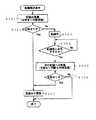
図2を参照して、磁気記録再生装置1における頭出し方法を詳細に説明する。ステップ201は、電源ON/OFFの判別である。
【0028】
電源ONであれば、ステップ202に分岐し頭出し動作が開始される。ステップ203では、FWD(フォーワード)遷移命令により、磁気テープ順方向に早送りを行なう。
【0029】
次にステップ204では、再生信号を用いて、クロッグ判別することにより、未記録部分の検出を行う。未記録部分が検出されない場合、ステップ203〜204を繰り返す。未記録部分を検出した場合、ステップ205に分岐する。
【0030】
ステップ205では、RVS(リバース)動作命令により、今度は磁気テープ逆方向に巻戻しを行う。
【0031】
次に、ステップ206では、再生信号を用いて、クロッグ判別することにより、記録部分の検出を行う。記録部分が検出されない場合、ステップ207に分岐する。記録部分が検出された場合、頭出し終了となる。
【0032】
ステップ207では、現在再生している磁気テープ領域がテープトップか否かを判断する。テープトップでなければ、ステップ205に分岐してステップ205〜206の動作が行われる。テープトップであれば、ステップ208に分岐する。
【0033】
なお、例えば磁気テープの最先端に例えば非磁性領域が形成されていることにより、磁気テープのトップが検出される。
【0034】
ステップ208では、磁気テープのトップ近傍(先頭領域)に、数V(垂直走査期間)あるい数秒間、RF信号を記録する。このRF信号は、クロッグ判別に用いることのできる信号であればよい。
【0035】
続いて、ステップ209では、つなぎ撮り命令により、図5(A)に示すつなぎ撮り動作を行う。即ち、ステップ208における記録領域から磁気テープを巻き戻し、続いてステップ208における記録部分を順方向に再生して停止する。
【0036】
ステップ210では、前記順方向再生時、クロッグ判別によって正常な記録・再生が行われたか判断する。異常であれば目詰まり警告を発する(図1のLCDディスプレイ27)。正常であれば磁気テープをnewテープと判断して表示する。
【0037】
以上説明したように、本実施例の方法によれば、記録部分が検出されない場合においても、画像信号等の記録を行う前に、クロッグ判別、具体的にはクロッグ判別のために記録したRF信号の再生レベルを基準電源と比較することにより、磁気記録装置の異常を検出することができる。このため、本実施例によれば既記録テープをnewテープと誤認識することがなく、画像信号等の上書きによる誤消去が防止される。
【0038】
【実施例2】
図3は図1の磁気記録再生装置における記録方法を説明するフローチャートである。
【0039】
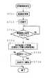
記録開始命令により、ステップ301では記録前準備(目詰まり判断実施)を行う。前回記録時に、図5に示すトラック合わせ区間にもRF信号が記録されており、磁気テープはトラック合わせ区間の手前で停止している。トラック合わせ区間に記録されたRF信号を再生し、RF信号のエンベロープ(レベル)を検出することにより(クロッグ判別)、前述の図2に示すステップ203〜209の動作と同様に目詰まり検出が行われる。
【0040】
ステップ302では、ステップ301に係る再生RF信号のレベルにより目詰まりか否かを判断する。
【0041】
目詰まりが検出されればステップ307に分岐して、目詰まり警告を発して終了する。
【0042】
目詰まりが検出されない場合、ステップ303に分岐し、記録停止命令(ステップ304)を受けるまで記録動作を行なう。
【0043】
記録停止命令を受けた場合、次の記録への準備及び目詰まり判断を再度行なう。この動作は前述のステップ301で説明した動作と同じである。
【0044】
続いて、目詰まりが検出されれば警告を出し(ステップ307)、異常が無い場合は終了する。
【0045】
以上説明したように、本実施例の方法によれば、記録動作(操作)の前後に目詰まり判断を行うことにより、今回記録前の目詰まり、及び今回記録する際に始めて発生する目詰まり両方が検出される。加えて、従来使用されていない、トラック合わせに用いられる該記録媒体のトラック合わせ領域に、所定の信号を記録し、この記録された所定の信号を再生し、例えば再生レベルよりすることにより、磁気記録再生装置の正常又は異常が判断される。この方法によれば、記録媒体を先頭領域まで巻き戻したりする手間が省けると共に、記録媒体の有効活用が為される。
【0046】
【実施例3】
図4は図1の磁気記録再生装置における検索動作を説明するフローチャートである。
【0047】
操作者の検索命令を受けた磁気記録装置は、ステップ401において、例えば前回の記録の最終部分から磁気テープをRVS(リバース)方向に巻戻す。
【0048】
続いて、ステップ402では、上記巻き戻しと共に再生を行うことにより、記録部分の検出をする。記録部分が検出された場合、検索RVS(リバース)動作は終了する。
【0049】
記録部分が検出されない場合、ステップ403に分岐し、現在巻き戻されかつ再生されている領域が磁気テープのトップであるか否かを判断する。テープトップでなければ、ステップ402に分岐する。テープトップであれば、ステップ404に分岐する。
【0050】
続いて、ステップ403〜406では、前述の図2に示すステップ207〜ステップ210の動作を行い、目詰まりの検出、警告を行う。
【0051】
以上説明したように、本実施例の方法によれば、検索動作(操作)においても、目詰まり判断を行うことにより、現在の装置の状態を正確に認識できると共に、磁気ヘッドの目詰まりにより記録部分が見つからないために、既記録磁気テープをnewテープと混同するようなミスが防止される。
【0052】
また、磁気テープのある領域に、例えばテープトップ領域に、画像信号等を記録しない領域を設けてヘッド目詰まり検出に供与することも好ましい。
【0053】
以上、本発明を上記実施例に即して説明したが、本発明は上記態様にのみ限定されるものでなく、本発明の原理に準ずる各種態様を含むものである。
【0054】
【発明の効果】
以上説明したように、本発明によれば、記録、再生、検索等の操作前に、所定の信号を、例えば磁気テープのトップ領域、あるいはトラック合わせ領域に記録し、再生されたRF信号のレベルを検出することにより、磁気記録再生装置のヘッドの目詰まり等の異常が事前に検出される。このため、再生の際ヘッド目詰まりにより前回記録領域が検出されないにも拘らず、記録済み領域を未記録領域と誤認して、記録領域を上書きするような誤記録が防止される。また、newテープに対しても、使用前に所定の信号を書き込み、かつ再生して再生レベルを検出することによりヘッドの目詰まりが事前に検出される。
【0055】
また、本発明によれば、記録動作(操作)の前後に目詰まり判断を行うことにより、今回記録前の目詰まり、及び今回記録する際に始めて発生する目詰まり両方が検出される。この方法によれば、記録媒体を先頭領域まで巻き戻したりする手間が省ける。
【図面の簡単な説明】
【図1】本発明の実施例に係る磁気記録再生装置の概略構成を示すブロック図である。
【図2】本発明の第1の実施例に係る図1の磁気記録再生装置における頭出し方法を説明するフローチャートである。
【図3】本発明の第2の実施例に係る図1の磁気記録再生装置における記録方法を説明するフローチャートである。
【図4】本発明の第2の実施例に係る図1の磁気記録再生装置における検索方法を説明するフローチャートである。
【図5】つなぎ撮り動作を説明するための磁気テープ及び再生RF信号のエンベロープを示す図である。
(A)は、つなぎ撮り動作を説明する磁気テープを示す。
(B)、(C)は、クロッグ信号を説明するための、再生RF信号のエンベロープを示し、
(B)は、標準モードでの再生RF信号のエンベロープであり、
(C)は、倍速モードでの再生RF信号のエンベロープである。
【図6】従来のつなぎ撮りの際の頭出し方法を説明するためのフローチャートである。
【図7】従来のつなぎ撮りの際の磁気ヘッドの目詰まり検出方法を説明するためのフローチャートである。
【符号の説明】
20 搬送メカ
21 ストロボ
22 カメラ(CCDカメラ)
23 操作パネル
24 メモリ(不揮発性メモリ)
25 システムコントロール回路
26 表示用メモリ
27 LCD(液晶)ディスプレイ
28 磁気記録再生メカデッキ
29 磁気記録再生処理部
30 カセット
31 搬送メカコントロール回路
32 A/D(アナログ/デジタル)変換回路
33 SSG(Sync Signal Generator;同期信号発生器)
34 A/D・D/A(アナログ/デジタル・アナログ/デジタル)変換回路
35 記録再生サーボ回路
36 印刷装置[0001]
[Industrial application fields]
The present invention relates to an abnormality detection method for a magnetic recording / reproducing apparatus, and more particularly to a magnetic head clogging detecting method for detecting clogging of a magnetic head in a magnetic recording / reproducing apparatus.
[0002]
[Prior art]
Conventionally, in a magnetic recording / reproducing apparatus such as an 8 mm VTR, recording and non-recording are discriminated by clog (CLOG) discrimination only when continuous shooting (recording) is performed (see, for example, the SONY 8 mm movie service manual). “Continuous shooting” is to perform another recording following a certain recording, and “clog discrimination” is to compare the envelope of the reproduced RF signal with the reference power source, that is, by detecting the level. In this method, a recorded portion and an unrecorded portion of the magnetic recording medium are discriminated.
[0003]
FIG. 5A is an explanatory diagram of a magnetic tape for explaining a continuous shooting operation.
[0004]
As shown in FIG. 5A, during recording on the magnetic tape, recording on the tape is stopped by a pause command, and then rewinding is performed, and a part of the previously recorded portion is reproduced and stopped. During the playback operation, the recorded part is confirmed by the clog signal.
[0005]
5 (B) to 5 (C) are reproduction RF signal envelopes for explaining the clog discrimination. FIG. 5 (B) shows the SP mode (standard mode), and FIG. Each of the RF signals in the (double speed mode) is shown.
[0006]
In the RF signals shown in FIGS. 5B and 5C, since the inclination of the reproducing magnetic head with respect to the track is different, SP and LP are distinguished from each other by the difference in the depth between the peak and valley of the signal. It is also possible to do. The recording / non-recording determination can be performed when the level of the envelope of the RF signal is 0 or low when the recording is not performed.
[0007]
FIG. 6 is a flowchart for explaining a method for cueing an unrecorded portion of a recording medium at the time of conventional joining shooting.
[0008]
Referring to FIG. 6, in the above conventional cueing method, cueing operation of an unrecorded area of the magnetic tape is started before start of continuous recording. In step 601, a FWD (forward) transition command is output and the reproduction of the magnetic tape is started. Next, in step 602, it is determined whether or not an unrecorded portion has been detected by clog discrimination based on the RF signal reproduced in the previous step. When an unrecorded portion is not detected (No), the process returns to step 601 and the magnetic tape is further reproduced in the forward direction. If an unrecorded portion is detected (Yes), the process branches to step 603.
[0009]
In step 603, an RVS (reverse) operation command is output, and the magnetic tape is rewound and reproduced in the reverse direction. Subsequently, in
[0010]
FIG. 7 is a flowchart for explaining a conventional method for detecting clogging of a magnetic head during continuous shooting.
[0011]
Referring to FIG. 7, in the above-described conventional method for detecting clogging of a magnetic head, in response to a recording start command, the magnetic recording apparatus starts preparation for recording in step 701. Next, in
[0012]
[Problems to be solved by the invention]
However, in the conventional cueing operation method shown in FIG. 6, since clogging of the head is not executed, even if the recorded portion of the magnetic recording medium is not detected due to clogging of the head, there is no magnetic recording. The recording medium, that is, the NEW (new) tape and the magnetic recording device judge. For this reason, there is a risk that the recorded part is overwritten and erased entirely.
[0013]
Further, in the conventional recording method shown in FIG. 7 (see FIG. 5A), since clogging is detected after recording is once completed, clogging cannot be detected and determined before recording. Therefore, since an abnormality such as clogging of the head cannot be detected before recording, inconveniences such as a loss of recording already occur when the abnormality is detected.
[0014]
Furthermore, since the clog discrimination is not performed during the conventional search and editing, the recorded part may be erroneously recognized as an unrecorded part. Specifically, at the time of retrieval (reproduction), the recorded portion cannot be reproduced, and the magnetic head is moved to the tape top (first area), and the magnetic recording / reproducing apparatus says that this magnetic tape is a new tape (unrecorded). A message may be output.
[0015]
The present invention has been made in view of such a problem, and in a magnetic recording / reproducing apparatus, an abnormality of the apparatus such as clogging of a head is accurately detected. An object of the present invention is to provide an abnormality detection method for a magnetic recording / reproducing apparatus for preventing erroneous recording caused by misidentification with a recording area.
[0016]
[Means for Solving the Problems]
[0018]
Inorder to achieve the above object , an abnormality detection method for a magnetic recording / reproducing apparatus according to the present inventionrecords a predetermined signal in a predetermined area of a recording medium and reproduces the recorded signal. And determining whether the magnetic recording / reproducing apparatus is normal or abnormal based on a reproduction signal, and the predetermined area is a track alignment section of the recording medium used for track alignment, and the predetermined area recorded in the track alignment section It is characterized by determining whether the magnetic recording / reproducing apparatus is normal or abnormal by reproducing the signal.
[0019]
In order to achieve the above object, the abnormality detection method for a magnetic recording / reproducing apparatus of the present invention is a method for detecting clogging of a magnetic head of a magnetic recording / reproducing apparatus when cueing a recording medium. If it is ON, it branches to a cueing operation. If it is OFF, power is input. In the cueing operation, the recording medium is fast-forwarded in the forward direction and recorded in atrack alignment section. A signal is reproduced and an unrecorded part is determined by clog discrimination. When the unrecorded part is not detected, the reproduction and determination are further performed. When the unrecorded part is detected, the signal is rewound in the reverse direction. The recording portion is determined by discrimination, and when the recording portion is detected, the cueing operation is finished. When the recording portion is not detected, it is determined whether or not the reproduced portion is the head region of the recording medium. If it is not the head area, the determination and playback are further continued.If it is the head area, a signal is recorded and played back in the head area, and a clog is determined using the playback signal. The clogging of the magnetic recording device is detected.
[0020]
Abnormality detecting method for a magnetic recording and reproducing apparatus of the present invention, in order to achieve the above object, when recordingto the recording medium, a method of detecting clogging of a magnetic head of a magnetic recording and reproducing apparatus, themagnetic head by clog discrimination When clogging is detected, a warning is issued and the process is terminated. When cloggingis not detected, recording is performed. When the recording is stopped, a predetermined signal is recorded in the track alignment section. Then, the clogging of themagnetic head is determined again by the clog discrimination using the reproduction signal, a warning is issued when clogging is detected, and the recording operation is terminated when clogging is not detected. It is characterized by that.
[0022]
[Action]
Based on the above configuration, according to the present invention, when recording, reproduction, and search are performed, a predetermined signal is recorded in a predetermined area of the recording medium, that is, atrack alignment area , and this recording is reproduced. For example, abnormalities such as clogging of the head of the magnetic recording / reproducing apparatus are detected by detecting the level of the reproduced recording signal. For this reason, it is possible to prevent erroneous recording such that the recorded area is mistakenly recognized as an unrecorded area and the recorded area is overwritten although the recorded area is not detected due to clogging of the head during reproduction. Also, the clogging of the head is detected by writing a predetermined signal before use on the new tape and reproducing it to perform clog discrimination.
[0023]
Further, according to the present invention, the clog can be determined using the track alignment portion when the next recording or the like is started, and normality or abnormality of the magnetic recording / reproducing apparatus is determined. According to this method, the trouble of rewinding the recording medium to the head area can be saved.
[0024]
【Example】
Embodiments of the present invention will be described below with reference to the drawings.
[0025]
[Example 1]
FIG. 1 is a block diagram showing a schematic configuration of a magnetic recording / reproducing apparatus according to an embodiment of the present invention, and FIG. 2 is a flowchart for explaining a cueing method in the magnetic recording / reproducing apparatus of FIG.
[0026]
The magnetic recording / reproducing apparatus of the present embodiment shown in FIG. 1 is described in detail in Japanese Patent Application No. 7-59876 and the like. The
[0027]
With reference to FIG. 2, the cueing method in the magnetic recording / reproducing apparatus 1 will be described in detail. Step 201 is determination of power ON / OFF.
[0028]
If the power is ON, the process branches to step 202 and the cueing operation is started. In step 203, fast forward is performed in the forward direction of the magnetic tape in accordance with an FWD (forward) transition command.
[0029]
Next, in step 204, the unrecorded portion is detected by performing clog discrimination using the reproduction signal. If an unrecorded part is not detected, steps 203 to 204 are repeated. If an unrecorded part is detected, the process branches to step 205.
[0030]
In step 205, in accordance with the RVS (reverse) operation command, rewinding is performed in the reverse direction of the magnetic tape.
[0031]
Next, in step 206, the recorded portion is detected by performing clog discrimination using the reproduction signal. If no recorded portion is detected, the process branches to step 207. When the recorded portion is detected, the cueing ends.
[0032]
In
[0033]
For example, the top of the magnetic tape is detected by forming, for example, a nonmagnetic region at the forefront of the magnetic tape.
[0034]
In step 208, an RF signal is recorded in the vicinity of the top (leading region) of the magnetic tape for several V (vertical scanning period) or for several seconds. The RF signal may be any signal that can be used for clog discrimination.
[0035]
Subsequently, in step 209, a joining shooting operation shown in FIG. 5A is performed by a joining photography command. That is, the magnetic tape is rewound from the recording area in step 208, and then the recorded portion in step 208 is reproduced in the forward direction and stopped.
[0036]
In step 210, it is determined whether or not normal recording / reproduction is performed by the clog discrimination during the forward reproduction. If it is abnormal, a clogging warning is issued (LCD display 27 in FIG. 1). If normal, the magnetic tape is judged as a new tape and displayed.
[0037]
As described above, according to the method of the present embodiment, even when a recording portion is not detected, before recording an image signal or the like, an RF signal recorded for clog discrimination, specifically for clog discrimination, is recorded. By comparing the reproduction level with the reference power source, it is possible to detect an abnormality in the magnetic recording apparatus. Therefore, according to the present embodiment, the recorded tape is not erroneously recognized as a new tape, and erroneous erasure due to overwriting of an image signal or the like is prevented.
[0038]
[Example 2]
FIG. 3 is a flowchart for explaining a recording method in the magnetic recording / reproducing apparatus of FIG.
[0039]
In step 301, in accordance with a recording start command, preparation before recording (clogging determination is performed) is performed. At the time of the previous recording, the RF signal is also recorded in the track alignment section shown in FIG. 5, and the magnetic tape is stopped before the track alignment section. By reproducing the RF signal recorded in the track alignment section and detecting the envelope (level) of the RF signal (clog discrimination), clogging is detected in the same manner as the operations in steps 203 to 209 shown in FIG. Is called.
[0040]
In step 302, it is determined whether clogging occurs based on the level of the reproduction RF signal related to step 301.
[0041]
If clogging is detected, the process branches to step 307, where a clogging warning is issued and the process ends.
[0042]
If no clogging is detected, the process branches to step 303, and the recording operation is performed until a recording stop command (step 304) is received.
[0043]
When a recording stop command is received, preparation for the next recording and determination of clogging are performed again. This operation is the same as that described in step 301 above.
[0044]
Subsequently, a warning is issued if clogging is detected (step 307), and the process ends if there is no abnormality.
[0045]
As described above, according to the method of this embodiment, by performing the clogging determination before and after the recording operation (operation), both the clogging before the current recording and the clogging that occurs for the first time during the current recording are performed. Is detected. In addition, a predetermined signal is recorded in a track alignment area of the recording medium used for track alignment, which has not been used in the past, and the recorded predetermined signal is reproduced, for example, based on a reproduction level, thereby magnetically Whether the recording / reproducing apparatus is normal or abnormal is determined. According to this method, the trouble of rewinding the recording medium to the head region can be saved and the recording medium can be effectively used.
[0046]
[Example 3]
FIG. 4 is a flowchart for explaining a search operation in the magnetic recording / reproducing apparatus of FIG.
[0047]
In
[0048]
Subsequently, in
[0049]
If the recorded portion is not detected, the process branches to step 403, where it is determined whether or not the currently rewound and reproduced area is the top of the magnetic tape. If not the tape top, the process branches to step 402. If it is a tape top, the process branches to step 404.
[0050]
Subsequently, in steps 403 to 406, the operations in
[0051]
As described above, according to the method of the present embodiment, even in the search operation (operation), it is possible to accurately recognize the current state of the apparatus by performing the clogging determination, and to record the clogging of the magnetic head. Since the portion is not found, mistakes that confuse the recorded magnetic tape with the new tape are prevented.
[0052]
In addition, it is also preferable to provide an area where no image signal or the like is recorded in an area of the magnetic tape, for example, in the tape top area, and to provide head clogging detection.
[0053]
As mentioned above, although this invention was demonstrated according to the said Example, this invention is not limited only to the said aspect, Various aspects based on the principle of this invention are included.
[0054]
【The invention's effect】
As described above, according to the present invention, a predetermined signal is recorded in, for example, the top area of the magnetic tape or the track alignment area before the operation of recording, reproduction, search, etc., and the level of the reproduced RF signal By detecting this, abnormalities such as clogging of the head of the magnetic recording / reproducing apparatus are detected in advance. Therefore, it is possible to prevent erroneous recording such that the recorded area is mistakenly recognized as an unrecorded area and the recording area is overwritten although the previous recording area is not detected due to clogging of the head during reproduction. Also, for a new tape, clogging of the head is detected in advance by writing a predetermined signal before use and reproducing it to detect the reproduction level.
[0055]
Further, according to the present invention, by performing the clogging determination before and after the recording operation (operation), both the clogging before the current recording and the clogging that occurs for the first time when recording this time are detected. According to this method, the trouble of rewinding the recording medium to the head area can be saved.
[Brief description of the drawings]
FIG. 1 is a block diagram showing a schematic configuration of a magnetic recording / reproducing apparatus according to an embodiment of the present invention.
FIG. 2 is a flowchart illustrating a cueing method in the magnetic recording / reproducing apparatus of FIG. 1 according to the first embodiment of the present invention.
FIG. 3 is a flowchart illustrating a recording method in the magnetic recording / reproducing apparatus of FIG. 1 according to a second embodiment of the present invention.
4 is a flowchart illustrating a search method in the magnetic recording / reproducing apparatus of FIG. 1 according to a second embodiment of the present invention.
FIG. 5 is a diagram showing an envelope of a magnetic tape and a reproduction RF signal for explaining a continuous shooting operation.
(A) shows a magnetic tape for explaining a stitching operation.
(B) and (C) show the envelope of the reproduction RF signal for explaining the clog signal,
(B) is an envelope of the reproduction RF signal in the standard mode,
(C) is an envelope of the reproduction RF signal in the double speed mode.
FIG. 6 is a flowchart for explaining a conventional cueing method at the time of joining shots.
FIG. 7 is a flowchart for explaining a conventional method for detecting clogging of a magnetic head at the time of continuous shooting.
[Explanation of symbols]
20 Transport mechanism
21 Strobe
22 Camera (CCD camera)
23 Operation panel
24 memory (non-volatile memory)
25 System control circuit
26 Display memory
27 LCD display
28 Magnetic recording and playback mechanism deck
29 Magnetic recording / playback processor
30 cassettes
31 Transport mechanism control circuit
32 A / D (analog / digital) conversion circuit
33 SSG (Sync Signal Generator)
34 A / D / D / A (Analog / Digital / Analog / Digital) Conversion Circuit
35 Recording / reproducing servo circuit
36 Printer
Claims (3)
Translated fromJapanese記録媒体の所定領域に所定の信号を記録し、記録された信号を再生し、再生信号に基づき前記磁気記録再生装置の正常又は異常を判定し、
前記所定領域は、トラック合わせに用いられる該記録媒体のトラック合わせ区間であり、
前記トラック合わせ区間に記録された前記所定の信号を再生することにより、磁気記録再生装置の正常又は異常を判定することを特徴とする磁気記録再生装置の異常検出方法。In the magnetic recording / reproducing apparatus abnormality detection method,
Recording a predetermined signal in a predetermined area of the recording medium, reproducing the recorded signal, determining normality or abnormality of the magnetic recording / reproducing apparatus based on the reproduction signal,
The predetermined area is a track alignment section of the recording medium used for track alignment,
By reproducing the predetermined signal recorded on the track alignment section, the abnormality detecting method for a magnetic recording and reproducing apparatusyou and judging a normal or abnormal in the magnetic recording and reproducing apparatus.
電源がONかOFFかを判定して、ONであれば頭出し動作に分岐し、OFFであれば電源を入力し、
前記頭出し動作において、前記記録媒体を順方向に早送りしてトラック合わせ区間に記録された所定の信号を再生してクロッグ判別により未記録部分を判定し、
前記未記録部分を検出しない場合には更に前記再生及び判定を行い、
前記未記録部分を検出する場合には逆方向に巻戻してクロッグ判別により記録部分を判定し、
前記記録部分を検出する場合は頭出し動作を終了し、
前記記録部分を検出しない場合は再生されている部分が該記録媒体の先頭領域であるか否かを判定し、
前記先頭領域ではない場合には更に前記判定及び再生を続行し、
前記先頭領域である場合には、該先頭領域に信号を記録して、再生し、
再生信号を用いてクロッグ判別し、前記磁気記録装置の目詰まりを検出することを特徴とする磁気記録再生装置の異常検出方法。In a method for detecting clogging of a magnetic head of a magnetic recording / reproducing apparatus when cueing a recording medium,
Determine whether the power is ON or OFF. If it is ON, branch to the cueing operation. If it is OFF, input the power.
In the cueing operation, the recording medium is fast-forwarded in the forward directionto reproduce a predetermined signal recorded in the track alignment section and determine an unrecorded portion by clog discrimination,
If the unrecorded part is not detected, the reproduction and determination are further performed.
When detecting the unrecorded part, rewind in the reverse direction and determine the recorded part by clog discrimination,
When detecting the recording portion, the cueing operation is terminated,
If the recording part is not detected, it is determined whether the part being reproduced is the head area of the recording medium,
If it is not the top area, continue the determination and playback,
If it is the head area, record the signal in the head area and play it,
An abnormality detection method for a magnetic recording / reproducing apparatus, wherein clogging is performed using a reproduction signal to detect clogging of the magnetic recording apparatus.
クロッグ判別により前記磁気ヘッドの目詰まりを判定し、
目詰まりを検出する場合には警告を発して終了し、
目詰まりを検出しない場合には記録をし、
前記記録を停止する際、トラック合わせ区間に所定の信号を記録して再生し、
再生信号を用いて再度クロッグ判別により前記磁気ヘッドの目詰まりを判定し、
目詰まりを検出する場合には警告を発し、
目詰まりを検出しない場合には前記記録動作を終了することを特徴とする磁気記録再生装置の異常検出方法。When recordingto the recording medium, a method of detecting clogging of a magnetic head of a magnetic recording and reproducing apparatus,
Determine clogging of themagnetic head by clog discrimination,
If clogging is detected, exit with a warning,
If no cloggingis detected, record
When the recording is stopped, a predetermined signal is recorded and reproduced in the track alignment section,
Determine the clogging of themagnetic head by the clog discrimination again using the reproduction signal,
If a clog is detected, a warning will be issued,
An abnormality detection method for a magnetic recording / reproducing apparatus, wherein the recording operation is terminated when no clogging is detected.
Priority Applications (1)
| Application Number | Priority Date | Filing Date | Title |
|---|---|---|---|
| JP11913795AJP3693380B2 (en) | 1995-04-20 | 1995-04-20 | Abnormality detection method for magnetic recording / reproducing apparatus |
Applications Claiming Priority (1)
| Application Number | Priority Date | Filing Date | Title |
|---|---|---|---|
| JP11913795AJP3693380B2 (en) | 1995-04-20 | 1995-04-20 | Abnormality detection method for magnetic recording / reproducing apparatus |
Publications (2)
| Publication Number | Publication Date |
|---|---|
| JPH08293167A JPH08293167A (en) | 1996-11-05 |
| JP3693380B2true JP3693380B2 (en) | 2005-09-07 |
Family
ID=14753856
Family Applications (1)
| Application Number | Title | Priority Date | Filing Date |
|---|---|---|---|
| JP11913795AExpired - Fee RelatedJP3693380B2 (en) | 1995-04-20 | 1995-04-20 | Abnormality detection method for magnetic recording / reproducing apparatus |
Country Status (1)
| Country | Link |
|---|---|
| JP (1) | JP3693380B2 (en) |
Families Citing this family (2)
| Publication number | Priority date | Publication date | Assignee | Title |
|---|---|---|---|---|
| KR100605945B1 (en)* | 1999-07-24 | 2006-08-02 | 삼성전자주식회사 | Tape driving path automatic adjustment device and method of image recording / playback device |
| US6747828B2 (en)* | 2001-02-22 | 2004-06-08 | Samsung Electronics Co., Ltd. | Apparatus and method for detecting an abnormality in a recorded signal |
- 1995
- 1995-04-20JPJP11913795Apatent/JP3693380B2/ennot_activeExpired - Fee Related
Also Published As
| Publication number | Publication date |
|---|---|
| JPH08293167A (en) | 1996-11-05 |
Similar Documents
| Publication | Publication Date | Title |
|---|---|---|
| US5432650A (en) | Magnetic tape recording/reproducing apparatus having automatic mode control | |
| US4607297A (en) | Apparatus for detecting clogging of head gap | |
| JP3693380B2 (en) | Abnormality detection method for magnetic recording / reproducing apparatus | |
| US6906882B2 (en) | Recording and reproducing apparatus and method | |
| KR100209614B1 (en) | Index and search method of DBR | |
| US20060204212A1 (en) | Information recording/reproducing device | |
| JP2549211Y2 (en) | Recording error detecting device in magnetic recording / reproducing device | |
| EP1672639B1 (en) | Information recording/reproducing device | |
| JP3359053B2 (en) | Magnetic recording / reproducing device | |
| JP3128484B2 (en) | Magnetic recording / reproducing device | |
| KR940004591B1 (en) | Automatic editting method in vcr | |
| JP2750984B2 (en) | Magnetic recording / reproducing device | |
| JPH0660494A (en) | Magnetic recording and reproducing device | |
| JPH05307792A (en) | Magnetic tape device | |
| JPH08167202A (en) | Recording device and recording / reproducing device | |
| KR940027493A (en) | Recording Screen Editing Navigation Device and Method | |
| JPH11232839A (en) | Monitoring and recording device | |
| JPH07110979A (en) | Tape recording / reproducing apparatus and tape recording / reproducing method | |
| JPH03273548A (en) | magnetic recording and reproducing device | |
| JPH0696403A (en) | Magnetic recording / reproducing device | |
| KR19990001710A (en) | Recording control method of video cassette recorder | |
| JPH0341601A (en) | Video floppy recording and playback device | |
| JPH05210957A (en) | Record status confirmation device | |
| JPH04252449A (en) | Magnetic recording and reproducing device | |
| JPH0877646A (en) | Magnetic recording / reproducing device |
Legal Events
| Date | Code | Title | Description |
|---|---|---|---|
| A131 | Notification of reasons for refusal | Free format text:JAPANESE INTERMEDIATE CODE: A131 Effective date:20050222 | |
| A521 | Written amendment | Free format text:JAPANESE INTERMEDIATE CODE: A523 Effective date:20050425 | |
| TRDD | Decision of grant or rejection written | ||
| A01 | Written decision to grant a patent or to grant a registration (utility model) | Free format text:JAPANESE INTERMEDIATE CODE: A01 Effective date:20050621 | |
| A61 | First payment of annual fees (during grant procedure) | Free format text:JAPANESE INTERMEDIATE CODE: A61 Effective date:20050621 | |
| R150 | Certificate of patent or registration of utility model | Free format text:JAPANESE INTERMEDIATE CODE: R150 | |
| S111 | Request for change of ownership or part of ownership | Free format text:JAPANESE INTERMEDIATE CODE: R313111 | |
| FPAY | Renewal fee payment (event date is renewal date of database) | Free format text:PAYMENT UNTIL: 20080701 Year of fee payment:3 | |
| R350 | Written notification of registration of transfer | Free format text:JAPANESE INTERMEDIATE CODE: R350 | |
| FPAY | Renewal fee payment (event date is renewal date of database) | Free format text:PAYMENT UNTIL: 20080701 Year of fee payment:3 | |
| FPAY | Renewal fee payment (event date is renewal date of database) | Free format text:PAYMENT UNTIL: 20090701 Year of fee payment:4 | |
| FPAY | Renewal fee payment (event date is renewal date of database) | Free format text:PAYMENT UNTIL: 20090701 Year of fee payment:4 | |
| FPAY | Renewal fee payment (event date is renewal date of database) | Free format text:PAYMENT UNTIL: 20100701 Year of fee payment:5 | |
| FPAY | Renewal fee payment (event date is renewal date of database) | Free format text:PAYMENT UNTIL: 20110701 Year of fee payment:6 | |
| LAPS | Cancellation because of no payment of annual fees |