JP3692617B2 - Charging time calculation method and battery pack - Google Patents
Charging time calculation method and battery packDownload PDFInfo
- Publication number
- JP3692617B2 JP3692617B2JP13157396AJP13157396AJP3692617B2JP 3692617 B2JP3692617 B2JP 3692617B2JP 13157396 AJP13157396 AJP 13157396AJP 13157396 AJP13157396 AJP 13157396AJP 3692617 B2JP3692617 B2JP 3692617B2
- Authority
- JP
- Japan
- Prior art keywords
- charging
- secondary battery
- time
- voltage
- current
- Prior art date
- Legal status (The legal status is an assumption and is not a legal conclusion. Google has not performed a legal analysis and makes no representation as to the accuracy of the status listed.)
- Expired - Fee Related
Links
Images


Classifications
- Y—GENERAL TAGGING OF NEW TECHNOLOGICAL DEVELOPMENTS; GENERAL TAGGING OF CROSS-SECTIONAL TECHNOLOGIES SPANNING OVER SEVERAL SECTIONS OF THE IPC; TECHNICAL SUBJECTS COVERED BY FORMER USPC CROSS-REFERENCE ART COLLECTIONS [XRACs] AND DIGESTS
- Y02—TECHNOLOGIES OR APPLICATIONS FOR MITIGATION OR ADAPTATION AGAINST CLIMATE CHANGE
- Y02E—REDUCTION OF GREENHOUSE GAS [GHG] EMISSIONS, RELATED TO ENERGY GENERATION, TRANSMISSION OR DISTRIBUTION
- Y02E60/00—Enabling technologies; Technologies with a potential or indirect contribution to GHG emissions mitigation
- Y02E60/10—Energy storage using batteries
Landscapes
- Tests Of Electric Status Of Batteries (AREA)
- Charge And Discharge Circuits For Batteries Or The Like (AREA)
- Secondary Cells (AREA)
Description
Translated fromJapanese【0001】
【発明の属する技術分野】
本発明は、充電時間演算方法およびバッテリパックに関する。特に、2次電池の充電が終了するまでの充電時間を、精度良く求めることができるようにする充電時間演算方法およびバッテリパックに関する。
【0002】
【従来の技術】
最近では、例えば電池監視用のマイコン(マイクロコンピュータ)を内蔵して2次電池の状態(例えば、2次電池の電圧や、充放電電流、残容量(2次電池の残りの容量)など)をモニタし、充電器、あるいはコンピュータなどの負荷との間でデータのやりとり(通信)を行う、スマートバッテリ(Smart Battery)(デュラセル(Duracell)社、インテル(Intel)社で提唱されている)あるいはインテリジェントバッテリなどと呼ばれるバッテリパックが実現されている。
【0003】
このようなバッテリパックを用いた場合には、そこから送信されてくる2次電池の状態を、充電器あるいは負荷側において、ユーザに報知することができる。また、バッテリパックにおいて、例えば、2次電池の充電時に、その充電が終了するまでの充電時間を求め、充電器に送信し、充電器では、バッテリパックから送信されてきた充電時間を表示するなどして、これを、ユーザに報知するようにすることもできる。
【0004】
【発明が解決しようとする課題】
ところで、スマートバッテリ(インテリジェントバッテリ)においては、例えば、電流積算法に基づいて、充電時間が求められるようになされている。即ち、満充電時から、いままでに流れた放電電流を時間積分し、その結果得られる容量(以下、適宜、空き容量という)を、充電電流で除算することにより、充電時間が求められるようになされている。
【0005】
従って、正確な充電時間を求めることが困難な課題があった。
【0006】
即ち、2次電池は、それを使用せず放置したままであっても、僅かではあるが放電が行われる。そして、この放電による僅かな放電電流により、空き容量に誤差が生じ、その結果、正確な充電時間を求めることが困難な課題があった。
【0007】
そこで、このような僅かな放電電流を検出することのできる、精度の高い電流検出回路を設け、その放電電流を考慮して、空き容量を算出する方法があるが、精度の高い電流検出回路は高価であり、バッテリパックが高コスト化することになる。
【0008】
また、正確な充電時間を求めるため、充電を行う際に、まず、2次電池を完全に放電させてから充電を行う方法があるが、これでは、充電に時間を要することになる。
【0009】
本発明は、このような状況に鑑みてなされたものであり、正確な充電時間を、容易に求めることができるようにするものである。
【0010】
【課題を解決するための手段】
請求項1に記載の充電時間演算方法は、2次電池が定電流で充電される第1の時間を、オープン電圧、および定電流充電時の2次電池の内部抵抗による電圧降下に基づいて求めるとともに、2次電池が定電圧で充電される第2の時間を、定電圧で充電されるときの2次電池のオープン電圧の変化を近似する指数関数に基づいて作成された、2次電池のオープン電圧が満充電電圧となるまでの時間をテーブル化した充電時間テーブルに基づいて求めることを特徴とする。
【0012】
請求項5に記載の充電時間演算方法は、2次電池のオープン電圧が所定の電圧であるときに、その2次電池が所定の放電電流を流し続けることのできる時間をテーブル化した時間テーブルに基づいて、2次電池が、充電電流と同一の放電電流を流し続けることのできる第1の時間を求め、第1の時間、および満充電状態にある2次電池が、充電電流と同一の放電電流を流し続けることのできる第2の時間から、充電時間を求めることを特徴とする。
【0013】
請求項8に記載のバッテリパックは、2次電池が定電流で充電される第1の時間を、オープン電圧、および定電流充電時の2次電池の内部抵抗による電圧降下に基づいて求める第1の時間算出手段と、2次電池が定電圧で充電される第2の時間を、定電圧で充電されるときの2次電池のオープン電圧の変化を近似する指数関数に基づいて作成された、2次電池のオープン電圧が満充電電圧となるまでの時間をテーブル化した充電時間テーブルに基づいて求める第2の時間検出手段とを備えることを特徴とする。
【0015】
請求項9に記載のバッテリパックは、2次電池のオープン電圧が所定の電圧であるときに、その2次電池が所定の放電電流を流し続けることのできる時間をテーブル化した時間テーブルに基づいて、2次電池が、充電電流と同一の放電電流を流し続けることのできる第1の時間を求める第1の時間算出手段と、第1の時間、および満充電状態にある2次電池が、充電電流と同一の放電電流を流し続けることのできる第2の時間から、充電時間を求める充電時間算出手段とを備えることを特徴とする。
【0016】
請求項1に記載の充電時間演算方法および請求項8に記載のバッテリパックにおいては、2次電池が定電流で充電される第1の時間が、オープン電圧、および定電流充電時の2次電池の内部抵抗による電圧降下に基づいて求められるとともに、2次電池が定電圧で充電される第2の時間が、定電圧で充電されるときの2次電池のオープン電圧の変化を近似する指数関数に基づいて作成された、2次電池のオープン電圧が満充電電圧となるまでの時間をテーブル化した充電時間テーブルに基づいて求められるようになされている。
【0018】
請求項5に記載の充電時間演算方法および請求項9に記載のバッテリパックにおいては、2次電池のオープン電圧が所定の電圧であるときに、その2次電池が所定の放電電流を流し続けることのできる時間をテーブル化した時間テーブルに基づいて、2次電池が、充電電流と同一の放電電流を流し続けることのできる第1の時間が求められ、第1の時間、および満充電状態にある2次電池が、充電電流と同一の放電電流を流し続けることのできる第2の時間から、充電時間が求められるようになされている。
【0019】
【発明の実施の形態】
以下に、本発明の実施例を説明するが、その前に、特許請求の範囲に記載の発明の各手段と以下の実施例との対応関係を明らかにするために、各手段の後の括弧内に、対応する実施例(但し、一例)を付加して、本発明の特徴を記述すると、次のようになる。
【0020】
即ち、請求項8に記載のバッテリパックは、定電流定電圧充電される2次電池を内蔵するバッテリパックであって、2次電池のオープン電圧を検出する検出手段(例えば、図1や図9に示す電池選択器10など)と、2次電池が定電流で充電される第1の時間を、オープン電圧、および定電流充電時の2次電池の内部抵抗による電圧降下に基づいて求める第1の時間算出手段(例えば、図5に示すプログラムの処理ステップS2など)と、2次電池が定電圧で充電される第2の時間を、定電圧で充電されるときの2次電池のオープン電圧の変化を近似する指数関数に基づいて作成された、2次電池のオープン電圧が満充電電圧となるまでの時間をテーブル化した充電時間テーブルに基づいて求める第2の時間検出手段(例えば、図5に示すプログラムの処理ステップS3など)とを備えることを特徴とする。
【0022】
請求項9に記載のバッテリパックは、外部から供給される充電電流により充電される2次電池を内蔵するバッテリパックであって、2次電池のオープン電圧を検出する検出手段(例えば、図12に示す電池選択器10など)と、2次電池のオープン電圧が所定の電圧であるときに、その2次電池が所定の放電電流を流し続けることのできる時間をテーブル化した時間テーブルに基づいて、2次電池が、充電電流と同一の放電電流を流し続けることのできる第1の時間を求める第1の時間算出手段(例えば、図13に示すプログラムの処理ステップS23など)と、第1の時間、および満充電状態にある2次電池が、充電電流と同一の放電電流を流し続けることのできる第2の時間から、充電時間を求める充電時間算出手段(例えば、図13に示すプログラムの処理ステップS24など)とを備えることを特徴とする。
【0023】
なお、勿論この記載は、各手段を上記したものに限定することを意味するものではない。
【0024】
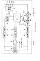
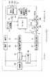
図1は、本発明を適用したパソコン(パーソナルコンピュータ)システムの構成例を示している。このパソコンシステムは、パソコン(本体)と、それに装着されたバッテリパックとから構成されており、パソコンは、例えば携帯型とされている。
【0025】
バッテリパックは、前述したような通信機能を有するもの(インテリジェントバッテリ)で、パソコンに対して着脱可能になされている。このバッテリパックは、2次電池として、例えば、リチウムイオン系の3つの電池(セル)E1乃至E3を有しており、これらのセルE1乃至E3は直列に接続されている。そして、セルE1の+端子は、パック(バッテリパック)の+端子2に接続されており、また、セルE3の−端子は、セルE1乃至E3に対して直列に接続されたFET4,5、および抵抗6を介して、パックのGND端子(グランド端子)8に接続されている。従って、セルE1乃至E3(以下、適宜、これらをまとめて2次電池Eともいう)の放電電流は、+端子2およびGND端子8を介して流れ(負荷に対して、+端子2およびGND端子8を介して放電電流が供給され)、また2次電池Eに対する充電電流も、この+端子2およびGND端子8を介して流れるようになされている。
【0026】
マイコン(マイクロコンピュータ)1は、例えば、CPUなどを内蔵し、アンプ11の出力に基づいて、セルE1乃至E3それぞれの電圧(セルの+端子と−端子との間の電圧)(以下、適宜、セル電圧という)を認識し、そのセル電圧に対応して、FET4,5のゲート(G)に印加する電圧を制御するようになされている。さらに、マイコン1は、アンプ7の出力に基づいて、2次電池Eに流れる電流(充電電流および放電電流)を認識し、その電流に対応しても、FET4,5のゲートに印加する電圧を制御するようになされている。即ち、これにより、マイコン1は、FET4,5をオン/オフ(スイッチング)させ、バッテリパックが過充電および過放電状態となることを防止するようになされている。
【0027】
また、マイコン1は、上述したようにして認識したセル電圧に基づいて、2次電池Eの容量(残容量)を算出するようにもなされている。さらに、マイコン1は、テーブル記憶部3に記憶されている各種のテーブルを参照することにより、2次電池Eを充電するのに要する充電時間を求める(演算する)ようにもなされている。また、マイコン1は、パックの通信端子9に接続されており、この通信端子9を介して、後述するマイコン21と、所定の通信手順にしたがって通信を行うようにもなされている。即ち、マイコン1は、通信端子9を介して送信されてくるデータ(コマンド)に応じて、所定の処理を行ったり、あるいは、2次電池Eの電圧(直列に接続されたセルE1乃至E3の、セルE1の+端子とセルE3の−端子との間の電圧)(以下、適宜、電池電圧という)や、セルE1乃至E3それぞれのセル電圧、充放電電流、2次電池Eの残容量などの2次電池Eの状態に関する情報(状態情報)、さらには、2次電池E(セルE1乃至E2)の充電に要する充電時間その他の情報も、通信端子9を介して出力するようになされている。
【0028】
テーブル記憶部3には、後述するような各種のテーブルが記憶されている。FET(電界効果トランジスタ)4のドレイン(D)は、2次電池Eの−端子(セルE3の−端子)と接続されており、そのソース(S)は、FET5のソースと接続されている。FET5のドレインは、抵抗6を介して、GND端子8と接続されている。なお、FET4には、そのソースとドレインとの間に、2次電池Eの放電電流が流れる方向に(従って、2次電池Eの充電電流が流れない方向に)、寄生ダイオード4Aが形成されている。また、FET5には、そのソースとドレインとの間に、2次電池Eの充電電流が流れる方向に(従って、2次電池Eの放電電流が流れない方向に)、寄生ダイオード5Aが形成されている。ここで、本実施例では、FET4および5は、そのゲートにHまたはLレベルが印加されたとき、それぞれオンまたはオフするようになされている。
【0029】
抵抗6は、電流検出用の微小抵抗値の抵抗で、その一端は、FET5のドレインと接続されており、その他端は、GND端子8と接続されている。アンプ7は、抵抗6に電流(充電電流および放電電流)が流れることにより生じる電圧降下(電圧)を、マイコン1で取扱い可能なレベルに調整し、マイコン1に供給するようになされている。電池選択器10は、例えば、マルチプレクサなどでなり、セルE1乃至E3それぞれを周期的に選択し、その選択したセルの+端子と−端子との間の電圧(セル電圧)を検出して、アンプ11に供給するようになされている。アンプ11は、アンプ7と同様に、電池選択器10から供給される電圧(セル電圧)を、マイコン1で取扱い可能なレベルに調整(変換)し、マイコン1に供給するようになされている。
【0030】
バッテリパックは、以上の2次電池E、マイコン1、+端子2、テーブル記憶部3、FET4,5、抵抗6、アンプ7、GND端子8、通信端子9、電池選択器10、およびアンプ11から構成されている。
【0031】
一方、パソコンは、マイコン21、パソコン部22、充電器23、+端子25、通信端子26、およびGND端子27から構成されている。
【0032】
マイコン21は、通信端子26を介して、マイコン1と通信を行うようになされている。即ち、マイコン21は、例えば、マイコン1に対し、所定のコマンドを送信し、また、マイコン1から送信されてくる状態情報やその他の情報を受信するようになされている。また、マイコン21は、パソコン部22および充電器23の制御も行うようになされている。
【0033】
パソコン部22は、パソコン本来の機能を有するブロックで、充電器23より供給される電圧および電流、あるいは、バッテリパックから供給される電圧および電流を電源として動作するようになされている。充電器23は、例えば、定電圧源および定電流源などで構成され、マイコン21の制御の下、パソコン部22に対し、電源としての電圧および電流を供給し、また、バッテリパックに対し、充電電流を供給するようになされている。
【0034】
+端子25は、充電器23の+端子と接続されている。通信端子26は、マイコン21と接続されている。GND端子27は、充電器23の−端子と接続されている。
【0035】
なお、パソコン部22は、充電器23と+端子25との接続点、および充電器23と−端子27との接続点と接続されている。また、+端子25、通信端子26、またはGND端子27は、バッテリパックが、パソコンに正常に装着されたとき、+端子2、通信端子9、またはGND端子8とそれぞれ接続されるようになされている。
【0036】
次に、その動作について説明する。パソコン部22が、バッテリパックを電源として動作する場合においては、2次電池Eの+端子(セルE1の+端子)、+端子2,25、パソコン部22、GND端子27,8、抵抗6、FET5(ドレイン・ソース間),FET4(ソース・ドレイン間)、2次電池Eの−端子(セルE3の−端子)の経路で、放電電流が流れる。
【0037】
このとき、マイコン1は、電池選択部10が周期的に出力するセルE1乃至E3それぞれのセル電圧を、アンプ11の出力に基づいて検出し、セルE1乃至E3それぞれのセル電圧のいずれかが、所定の第1の基準電圧(セルE1乃至E3が過放電状態になるおそれがある電圧)より小さくなると、FET5のゲートに、Lレベルを印加し、これによりFET5をオフにする。FET5の寄生ダイオード5Aは、充電電流が流れる方向、即ち放電電流がながれない方向に接続されているため、FET5がオフにされると、放電電流は遮断される。これにより、過放電が防止される。
【0038】
なお、マイコン1は、アンプ7の出力に基づいて、放電電流も検出しており、これが、所定の第1の基準電流(セルE1乃至E3が過放電状態になるおそれがある電流)より大きくなった場合にも、FET5をオフにさせ、これにより、放電電流を遮断させるようになされている。
【0039】
このように、放電電流が遮断されると(遮断される直前)、マイコン21は、充電器23を制御し、これにより、パソコン部22の電源として動作させるとともに、バッテリパックに充電電流を供給させる。即ち、この場合、充電器23の+端子、+端子25,2、2次電池E、FET4、寄生ダイオード5A、抵抗6、GND端子8,27、充電器23の−端子の経路で、充電電流が流れ、これにより2次電池Eに対する充電が開始される。しかしながら、この場合、寄生ダイオード5Aでは、FET5のソース・ドレイン間に比較して(FET5(FET4も同様)に、ある程度のレベルの電圧がゲートに印加されている場合、そのオン抵抗は小さな値になるので、そのソース・ドレイン間の電圧降下は微小なものである)、約0.6乃至0.8V程度の大きな電圧降下が生じるので、効率的な充電を行うことができない。
【0040】
そこで、マイコン1は、充電が開始されると、例えばそれにより生じる電圧降下(例えば、1V程度の電圧降下)を検出し、その電圧降下を検出すると、FET5のゲートに、強制的にHレベルを印加して、FET5をオンにする。これにより、充電器23の+端子、+端子25,2、2次電池E、FET4,5、抵抗6、GND端子8,27、充電器23の−端子の経路で、充電電流が流れ、効率的な充電が行われる。
【0041】
充電が行われている間、マイコン1は、放電中の場合と同様に、セル電圧を検出しており、セルE1乃至E3それぞれのセル電圧のうちのいすれかが、所定の第2の基準電圧(セルE1乃至E3が過充電状態になるおそれがある電圧)より大きくなると、FET4のゲートに、Lレベルを印加し、これによりFET4をオフにする。FET4の寄生ダイオード4Aは、放電電流が流れる方向、即ち充電電流がながれない方向に接続されているため、FET4がオフにされると、充電電流は遮断される。これにより、過充電が防止される。
【0042】
なお、マイコン1は、放電時における場合と同様に、アンプ7の出力に基づいて、充電電流を検出しており、これが、所定の第2の基準電流(例えば、第1の基準電流と同一の電流)より大きくなった場合にも、FET4をオフにさせ、これにより、充電電流を遮断させるようになされている。
【0043】
充電が終了し、パソコン部22が、再び、バッテリパックを電源として動作するようになされると、充電終了直後は、FET4はオフにされているから、2次電池Eの+端子、+端子2,25、パソコン部22、GND端子27,8、抵抗6、FET5,寄生ダイオード4A、2次電池Eの−端子の経路で、放電電流が流れる。しかしながら、この場合、寄生ダイオード4Aでは、上述した寄生ダイオード5Aと同様に大きな電圧降下が生じるので、効率的な放電を行うことができない。
【0044】
そこで、マイコン1は、放電が開始されると、例えばそれにより生じる電圧降下(例えば、0.4V程度の電圧降下)を検出し、その電圧降下を検出すると、FET4のゲートに、強制的にHレベルを印加して、FET4をオンにする。これにより、上述したように、2次電池Eの+端子、+端子2,25、パソコン部22、GND端子27,8、抵抗6、FET5,4、2次電池Eの−端子の経路で、放電電流が流れ、効率的な放電が行われる。
【0045】
バッテリパックが、パソコンに正常に装着されている場合には、上述したような充放電中を含めて、マイコン1と21との間で、通信端子9および26を介して通信が行われる。即ち、例えば、マイコン21が、マイコン1に対し、セルE1乃至E3のセル電圧や、残容量、充放電電流を問い合わせるコマンドを送信すると、マイコン1は、そのコマンドに対応して、上述したようにして検出(算出)しているセル電圧や、残容量、充放電電流を、マイコン21に送信する。
【0046】
また、例えば、マイコン21が、マイコン1に対し、2次電池Eの充電時間を問い合わせるコマンド(Atrate Time to Full)(例えば、0x05などのコード(0xは、それに続く数字が16進数であることを表す))を送信すると、マイコン1は、そのコマンドに対応して、テーブル記憶部3を参照しながら、充電時間を演算し、マイコン21に送信する。
【0047】
次に、このような2次電池の充電時間の演算方法について説明する。2次電池が、上述したようにリチウムイオン電池である場合、その残容量は、2次電池のオープン電圧と1対1に対応しており、従って、2次電池のオープン電圧がわかれば、その残容量もわかる。そして、残容量がわかれば、「全容量(=公称電池容量)」−「残容量」を計算することで、空き容量を求めることができ、この空き容量を、充電電流で除算することにより(「空き容量」/「充電電流」を計算することにより)、充電時間を求めることができる。
【0048】
そこで、まず、2次電池を、定電流定電圧で充電する場合、即ち、図2に示すように、その電池電圧V(t)が満充電電圧Vfullになるまでは、定電流Ichgで充電し、その後は、充電電流I(t)が充分小さくなるまで、定電圧Vchgで充電する場合の充電時間の演算方法について説明する。
【0049】
ここで、図2においては、時間をtで表してあり、充電電流はI(t)と、2次電池の電池電圧(充電電流が流れているときの電池電圧)はV(t)と、2次電池のオープン電圧はv(t)(同図において点線で示す)と、2次電池の内部抵抗はRと、2次電池の満充電電圧はVfullと、それぞれ表してある。また、図2において、Vchgは、充電器が出力する充電電圧を表す。従って、定電圧で充電が行われているときはV(t)=Vchgである。さらに、図2において、Ichgは、2次電池が定電流で充電されているときの充電電流を表す。従って、定電流で充電が行われているときはI(t)=Ichgである。
【0050】
なお、リチウムイオン電池の満充電電圧Vfullは、例えば4.2V程度で、充電電圧Vchgは、それより幾分高い電圧(例えば、4.25V/セル程度)とされる。また、充電電流Ichgは、1C/セル以下が推奨値とされている。ここで、Cは、Chargeの略で、1Cは、例えば、1000mAH(ミリアンペアアウワ)の容量の電池に対して1000mA(ミリアンペア)の電流を流すことを意味する。
【0051】
定電流定電圧充電においては、Ichg≦(Vchg−v(t))/Rのとき、即ち、2次電池のオープン電圧v(t)が、Vchg−RIchg以下である間は、充電電流Ichgにより充電が行われる。従って、2次電池のオープン電圧がxであるときの残容量をC(x)と表すとすると、2次電池が定電流で充電される時間、即ち、充電開始時(あるいは、充電時間の計算開始時)から、2次電池のオープン電圧v(t)がVchg−RIchgとなるまでの時間(第1の時間)Tchg1は、次式で計算することができる。
【0052】
Tchg1=(C(Vchg−RIchg)−C(vst))/Ichg・・・(1)
但し、vstは、充電開始時の2次電池のオープン電圧を表す。
【0053】
以上のように、時間Tchg1は、内部抵抗Rに電流Ichgが流れているときの電圧降下RIchgと、2次電池のオープン電圧vstから求めることができる。
【0054】
その後、2次電池が定電圧で充電される間、即ち、オープン電圧v(t)が、Vchg−RIchgから満充電電圧Vfullになるまでの間における充電電流Ichgは、(Vchg−v(t))/Rと表すことができるから、これに要する時間(第2の時間)Tchg2は、式(2)で表される電圧v(t)による積分で求めることができる。
【0055】
【数1】
式(1)または(2)それぞれから、Tchg1またはTchg2を求めた後は、次式により、充電時間Tchgを求めることができる。
【0057】
Tchg=Tchg1+Tchg2・・・(3)
【0058】
ところで、式(2)を計算するためには、定電圧充電中における2次電池のオープン電圧v(t)を知る必要がある。そこで、ここでは、オープン電圧v(t)を、例えば指数関数exで近似する。即ち、v(t)を、例えば、次式で近似する。
【0059】
v(t)=Vfull×k×e-1/t・・・(4)
但し、kは、所定の定数(以下、適宜、特性係数という)である。
【0060】
なお、特性係数kは、2次電池の特性に基づいて決定するようにする。即ち、特性係数kを、例えばk1,k2,k3,・・・と変えることにより、図3(a)に示すように、v(t)を近似する種々の曲線が得られるが、このような曲線のうち、その形状が充電時間を演算しようとする2次電池の特性に最も合致するものを選択し、その曲線を与えるkを、2次電池の特性係数として決定する。具体的には、例えば、2次電池を充電しながら、そのオープン電圧を実測し、その実測したオープン電圧の変化と最も近似する曲線を与える特性係数kを選択するようにすれば良い。
【0061】
また、2次電池の特性係数kを決定した後は、図3(b)に示すように、その特性係数kにより与えられる式(4)のv(t)が、種々の電圧v1,v2,v3,・・・それぞれから満充電電圧Vfullになるまでの時間t1,t2,t3,・・・を求め、これを、例えば、図4に示すように、テーブル化しておくようにする(このようなテーブルを、以下、適宜、充電時間テーブルという)。この充電時間テーブルは、Vchg−RIchgが、v1,v2,v3,・・・である場合に定電圧充電を行ったときそれぞれの、2次電池のオープン電圧v(t)が満充電電圧Vfullになるまでの時間、即ち、Tchg2を表すから、Vchg−RIchgが与えられれば、この充電時間テーブルを参照することで、式(4)を計算しなくても、時間Tchg2を求めることができる。
【0062】
なお、与えられたVchg−RIchgが、充電時間テーブルに登録された電圧v1,v2,v3,・・・のうちのいずれとも一致しない場合には、そのVchg−RIchgに対応する時間Tchg2は、例えば、充電時間テーブルの登録値を用いて線形補間などすることにより求めるようにすれば良い。
【0063】
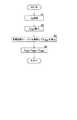
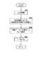
図5は、以上のようにして充電時間を求める場合の、図1のマイコン1の動作を説明するフローチャートである。マイコン1は、充電時間を問い合わせるコマンド(以下、適宜、充電時間コマンドという)を、マイコン21から受信すると、ステップS1において、電池選択器10から、アンプ11を介して、セルE1乃至E3それぞれのオープン電圧を受信する。即ち、マイコン1は、充電開始前(充電器23から充電電流の供給を受ける前)に、充電時間コマンドを受信したときは(但し、このとき、放電は行われていないものとする)、電池選択器10の出力を、セルE1乃至E3それぞれのオープン電圧として受信する。また、マイコン1は、充電中は、一旦、FET4をオフすることにより、充電電流を遮断し、その状態において、電池選択器10が出力する電圧を、セルE1乃至E3それぞれのオープン電圧として受信する。
【0064】
その後、ステップS2において、マイコン1は、ステップS1で受信したオープン電圧vstを用い、式(1)にしたがって、時間Tchg1を算出する。即ち、テーブル記憶部3には、2次電池のオープン電圧と、その残容量とを対応付けたテーブル(以下、適宜、容量テーブルという)が記憶されており、マイコン1は、この容量テーブルを参照して、式(1)におけるC(Vchg−RIchg)およびC(vst)を算出する(必要ならば、例えば線形補間などを行うことにより算出する)。そして、マイコン1は、式(1)にしたがった演算を行うことで、時間Tchg1を算出する。
【0065】
ここで、式(1)を計算するには、充電電圧Vchg、充電電流Ichg、および内部抵抗Rが必要となるが、充電電圧Vchgおよび充電電流Ichgは、通常、あらかじめ決められており、内部抵抗Rも、あらかじめ測定しておくことが可能であるから、マイコン1は、そのような充電電圧Vchgおよび充電電流Ichg、並びに、内部抵抗Rに基づき、式(1)の演算を行う。但し、充電電圧Vchgおよび充電電流Ichgは、充電器23を制御するマイコン21からマイコン1に対して送信させるようにしても良い。また、充電電流Ichgは、マイコン1に、アンプ7の出力に基づいて認識させるようにしても良い。
【0066】
なお、図1の実施例における場合のように、バッテリパックが、セルE1乃至E3のように、複数のセルを有する場合には、マイコン1は、それらのオープン電圧のうち、最も高いものを用いるようになされている。このように、最も高いオープン電圧を基準とするのは、仮に、最も低いオープン電圧を基準とすると、そのオープン電圧より高いオープン電圧のセルが、充電中に、高い電圧となることがあり、安全性の観点より好ましくないからである。
【0067】
時間Tchg1の算出後は、ステップS3に進み、マイコン1は、上述したようにして時間Tchg2を算出する。即ち、テーブル記憶部3には、図4に示したような充電時間テーブルが記憶されており、マイコン1は、この充電時間テーブルを参照し、Vchg−RIchgに対応する時間Tchg2を算出する(必要ならば、例えば線形補間などを行うことにより算出する)。あるいは、また、マイコン1は、式(4)で与えられる電圧v(t)を用いて、式(2)の積分を実行することで、時間Tchg2を算出する。なお、マイコン1に対する負荷の軽減の観点からは、時間Tchg2の算出は、充電時間テーブルを利用する手法を用いるのが望ましい。
【0068】
そして、マイコン1は、ステップS4に進み、式(3)にしたがって、充電時間Tchgを算出し、例えば、マイコン21に送信するなどして、処理を終了する。
【0069】
2次電池がリチウムイオン電池である場合のオープン電圧は、上述したように、その残容量に対応しており、従って、そのようなオープン電圧にしたがって充電時間を計算することで、正確な充電時間を求めることができる。即ち、例えば、2次電池から僅かな放電電流が流れたとしても、それによる残容量の減少は、そのオープン電圧に現れ、このオープン電圧に基づいて充電時間が求められるので、正確な充電時間を得ることができる。また、正確な充電時間を得るために、電流積算法における場合のように、充電を行う際に、2次電池を完全に放電させる必要もない。
【0070】
次に、図6に示すように、2次電池を、その電池電圧(2次電池の+端子と−端子との間の電圧)V(t)が満充電電圧Vfullとなるまでは定電流I(t)=Ichgで充電し、その後、充電電流をオン/オフしてパルス充電する場合の充電時間を演算する方法について説明する。なお、図6においては、2次電池のオープン電圧v(t)の図示は省略してある。また、図6では、パルス充電において、充電電流I(t)=Ichgは、期間T1だけオンした後、期間T2だけオフになり、再び、期間T1だけオンになることを繰り返すようになされている。そして、充電電流Ichgがオフにされている期間T2において、2次電池の電池電圧(これは、充電電流がオフしているときの電池電圧であるからオープン電圧に等しい)が、満充電電圧Vfull未満に降下しなくなったとき、パルス充電を終了するようになされている。
【0071】
この場合、パルス充電が開始されるまでは、即ち、電池電圧が(最初に)満充電電圧Vfullになるまでは、定電流定電圧充電における場合と同様の充電が行われる。従って、充電開始時から、パルス充電が開始されるまでの時間(定電流での充電が行われている時間)(第1の時間)Tchg1は、上述の式(1)で計算することができる。
【0072】
このとき充電を終了すると、2次電池の電池電圧は、IRロス分、即ち、RIchgだけ降下するから(厳密には、分極によっても降下するが、その大きさは、IRロス分に比較して小さいので、ここでは、無視する。但し、これを考慮するようにしても良い)、その後、2次電池は、パルス充電により、この電圧降下分RIchgだけ充電されると考えることができる。即ち、パルス充電によれば、2次電池のオープン電圧を、Vfull−RIchgからVfullにするまでの充電が行われると考えることができる。
【0073】
いま、vpst=Vfull−RIchgとおくと、パルス充電により増加する容量は、C(Vfull)−C(vpst)と表すことができ、また、パルス充電時の充電電流I(t)のデューティ比、即ち、T1/(T1+T2)をηとおくと、パルス充電により流れる電流値は、Ichg/ηと表すことができるから、パルス充電が行われている時間(電池電圧がVfullとなってから、充電が終了するまでの時間)(第2の時間)Tchg2は、次式で求めることができる。
【0074】
Tchg2=(C(Vfull)−C(vpst))/(Ichg/η)・・・(5)
【0075】
式(1)または(5)それぞれから、Tchg1またはTchg2を求めた後は、上述の式(3)により、充電時間Tchgを求めることができる。
【0076】
図7は、以上のようにして充電時間を求める場合の、図1のマイコン1の動作を説明するフローチャートである。マイコン1は、充電時間コマンドを、マイコン21から受信すると、ステップS11またはS12において、図5のステップS1またはS2における場合とそれぞれ同様の処理を行い、これにより、時間Tchg1を算出する。
【0077】
時間Tchg1の算出後は、ステップS13において、マイコン1は、パルス充電が開始されるときのオープン電圧vpst(=Vfull−RIchg)を求め、ステップS14に進み、vpstおよびηから、式(5)にしたがって時間Tchg2を算出する。
【0078】
ここで、充電電流I(t)=Ichgのオン/オフは、マイコン1がFET4を制御することにより行われるから、デューティ比ηは、マイコン1において認識することができる。
【0079】
なお、デューティ比η(T1およびT2)が固定値である場合には、その固定値を用いれば良いが、デューティ比ηが変化する場合、即ち、T1またはT2が変化する場合は、その変化するデューティ比ηの、例えば平均値などを用いるようにすることが可能である。
【0080】
ステップS14においてTchg2を計算した後は、ステップS15に進み、マイコン1は、図5のステップS4における場合と同様の処理を行い、処理を終了する。
【0081】
この場合も、2次電池のオープン電圧にしたがって充電時間が計算されるので、正確な充電時間を求めることができる。
【0082】
ところで、2次電池の内部抵抗Rは、例えば、図8(a)に示すように、環境温度Taによって変化する。また、充電中においては、2次電池自身の温度Ttも、例えば、図8(b)に示すように変化するが、内部抵抗Rは、この温度Ttのによっても変化する。従って、抵抗Rは、温度TaとTtの関数として、R(Ta,Tt)と表すことができるが、充電時間の算出には、この温度TaおよびTtを考慮した内部抵抗R(Ta,Tt)を用いた方が、その精度を、より向上させることができる。
【0083】
そこで、図9は、このように温度TaおよびTtを考慮して、充電時間を算出するパソコンシステムの構成例を示している。なお、図中、図1における場合と対応する部分には、同一の符号を付してあり、以下では、その説明は、適宜省略する。即ち、このパソコンシステムは、温度センサ31および温度テーブル記憶部32が新たに設けられている他は、図1のパソコンシステムと同様に構成されている。
【0084】
このパソコンシステムにおいては、温度センサ31において、環境温度Taが検出され、マイコン1に供給される。また、温度テーブル記憶部32には、図8(b)に示したグラフをテーブル化したテーブル(以下、適宜、温度テーブルという)が記憶されており、マイコン1は、充電が開始されてからの経過時間tに対応する温度Taを温度テーブルを参照することにより算出し、その温度Taと温度センサ31から受信した環境温度Taに基づいて、内部抵抗R(Ta,Tt)を算出する(例えば、R(Ta,Tt)と、TaおよびTtとを対応付けたテーブルが、テーブル記憶部3に記憶されており、そのテーブルを参照することで、R(Ta,Tt)を算出する)。その後は、マイコン1は、その内部抵抗R(Ta,Tt)を用いて、上述したように充電時間を算出する。
【0085】
この場合、より正確に、充電時間を求めることができる。
【0086】
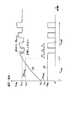
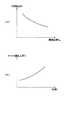
次に、例えばリチウムイオン電池などの2次電池を、所定の一定の電流で放電させると、そのオープン電圧v(t)は、例えば、図10に示すように、徐々に下降していく。いま、2次電池が過放電状態となる直前のオープン電圧をVemp(以下、適宜、放電終了電圧という)とし、オープン電圧が、この放電終了電圧Vempとなったときに2次電池の放電を終了するものとすると、オープン電圧が、満充電電圧Vfullから放電終了電圧Vempになるまでの放電時間TBは、あらかじめ計測しておくことができる。同様に、オープン電圧が、所定の電圧v(t)から放電終了電圧Vempになるまでの放電時間TAも、あらかじめ計測しておくことができる。従って、オープン電圧が、満充電電圧Vfullから所定の電圧v(t)になるまでの放電時間Tは、次式によって求めることができる。
【0087】
T=TB−TA・・・(6)
【0088】
そこで、図11に示すように、放電電流を種々の大きさに変えて、放電時間TAおよびTBを測定し、テーブル化しておけば(このようなテーブルを、以下、適宜、時間テーブルという)、この時間テーブルを参照することで、容易に、放電時間Tを求めることが可能となる。
【0089】
ところで、リチウムイオン電池などの2次電池には、充放電の可逆性がある。従って、放電時間Tは、オープン電圧がv(t)となっている2次電池を、満充電まで充電する充電時間に等しい。従って、充電電流および充電開始時のオープン電圧を検出し、それに対応する放電時間Tを、時間テーブルを参照して算出すれば、それが、充電時間となり、図1や図9の実施例では、このような時間テーブルを利用して、充電電流が一定の期間についての充電時間を求めるようにすることもできる。
【0090】
次に、時間テーブルを用いる場合においては、2次電池の充電が、可変の充電電流によって行われても、次のようにして、その可変の充電電流による充電時間を、ある程度の精度で求めることができる。即ち、例えば、充電開始後、所定の期間における可変の充電電流の移動平均値(以下、適宜、移動平均電流という)を求め、この移動平均電流で、充電がなされていくものと仮定することで、充電時間を求めることができる。
【0091】
ここで、所定の期間における充電電流の移動平均値とは、所定の期間に相当する時間窓が時刻の進行方向に移動していくことを考えた場合、現在時刻における充電電流が時間窓に取り込まれるときに、既に取り込まれている充電電流の総和から、その平均値(既に、時間窓内にある充電電流の総和を、時間窓の幅で除算したもの)を減算した値に、現在時刻における充電電流を加算した値を、時間窓の幅で除算した値である。従って、現在の移動平均値は、時間窓内の充電電流それぞれを記憶しておかなくても、前回の移動平均値を計算するのに用いた電流の総和値を記憶しておくだけで計算することができる。即ち、現在の移動平均値は、前回の移動平均値を計算するのに用いた電流の総和値から、その値を時間窓の幅で除算した値(これは、前回の移動平均値である)を減算し、その減算値に、現在時刻の充電電流を加算し、時間窓の幅で除算することにより求めることができる。
【0092】
この移動平均値は、充電電流を、時間窓の幅に対応する時間のタイムコンスタントの、抵抗とコンデンサでなるローパスフィルタ(RCフィルタ)を通過させて得られる値と等価である。
【0093】
移動平均電流を求めた後は、その移動平均電流および充電開始時のオープン電圧に対応する充電時間Tを、時間テーブルを参照して算出すれば良い。
【0094】
図12は、以上のようにして、充電時間を演算するパソコンシステムの構成例を示している。なお、図中、図1における場合と対応する部分については、同一の符号を付してあり、以下では、その説明は、適宜省略する。即ち、このパソコンシステムは、移動平均値を計算する移動平均値計算部41が新たに設けられている他は、図1のパソコンシステムと同様に構成されている。但し、テーブル記憶部3には、上述の時間テーブルが記憶されているものとする。
【0095】
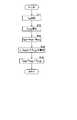
次に、図13のフローチャートを参照して、マイコン1が上述した時間テーブルを利用して充電時間を求める場合の動作について説明する。マイコン1は、充電時間コマンドを、マイコン21から受信すると、ステップS21において、図5のステップS1における場合と同様に、オープン電圧vstを受信する。そして、マイコン1は、ステップS22において、移動平均値計算部41に、充電電流の所定の期間における移動平均値、即ち、移動平均電流を送信させ、これを受信する。
【0096】
ここで、マイコン1では、充電が開始されると、アンプ7の出力に基づいて、例えば1秒ごとに充電電流が認識され、移動平均値計算部41に供給されており、移動平均値計算部41では、マイコン1からの充電電流の、例えば1分間における移動平均値が計算されるようになされている。
【0097】
即ち、移動平均値計算部41は、最初の1分間は、マイコン1から供給される60個の電流値を加算し、その内蔵するレジスタ(図示せず)に記憶する。さらに、移動平均値計算部41は、レジスタに記憶された値を1分間に相当する(1分間の間に加算した電流値のサンプル数)60で除算し、その結果得られる値を、移動平均値とする。そして、移動平均値計算部41は、マイコン1から61個目の電流値が供給されると、レジスタに記憶された値から、その値を60で除算した値、即ち、前回の移動平均値を減算し、その減算値に、61個目の電流値を加算する。さらに、移動平均値計算部41は、その加算値を、内蔵するレジスタに新たに記憶させるとともに、60で除算し、その除算結果を、移動平均値(移動平均電流)とする。以下、移動平均値計算部41では、マイコン1から電流値(現在の電流値)を受信するごとに、同様の処理が行われる。
【0098】
マイコン1は、移動平均電流を受信すると、ステップS23において、その移動平均電流およびオープン電圧vstに対応する時間TAおよびTBを、時間テーブルを参照することにより算出する。そして、ステップS24に進み、マイコン1は、式(6)にしたがって、充電時間Tを算出し、例えば、マイコン21に送信するなどして、処理を終了する。
【0099】
なお、図12の実施例においても、上述した温度TaおよびTtを考慮して充電時間を求めるようにすることが可能である。また、図12の実施例では、充電時間を求めるのに、充電時間コマンドを受信したときの充電電流の移動平均値を用いるようにしたが、充電時間は、充電時間コマンドを受信したときの充電電流そのものを用いて求めるようにすることも可能である。
【0100】
以上、本発明を、パソコンに装着可能な、通信機能を有するバッテリパックに適用した場合について説明したが、本発明は、その他、例えばパソコン以外の電子機器に装着可能なバッテリパックにも適用可能である。また、通信機能を有しないバッテリパックにも適用可能である。
【0101】
なお、本実施例においては、2次電池(セルE1乃至E3)を、リチウムイオン電池としたが、2次電池としては、リチウムイオン電池以外の電池を用いることも可能である。但し、2次電池は、その残容量と電池電圧とが1対1に対応しているものである必要がある。
【0102】
また、本実施例では、バッテリパックにおいて充電時間を求めるようにしたが、充電時間は、例えば、充電器側、即ち、ここでは、パソコンにおいて求めるようにすることも可能である。
【0103】
【発明の効果】
請求項1に記載の充電時間演算方法および請求項8に記載のバッテリパックによれば、2次電池が定電流で充電される第1の時間が、オープン電圧、および定電流充電時の2次電池の内部抵抗による電圧降下に基づいて求められ、また、2次電池が定電圧で充電される第2の時間が、定電圧で充電されるときの2次電池のオープン電圧の変化を近似する指数関数に基づいて作成された、2次電池のオープン電圧が満充電電圧となるまでの時間をテーブル化した充電時間テーブルに基づいて求められる。従って、精度良く充電時間を求めることが可能となる。
【0105】
請求項5に記載の充電時間演算方法および請求項9に記載のバッテリパックによれば、2次電池のオープン電圧が所定の電圧であるときに、その2次電池が所定の放電電流を流し続けることのできる時間をテーブル化した時間テーブルに基づいて、2次電池が、充電電流と同一の放電電流を流し続けることのできる第1の時間が求められ、第1の時間、および満充電状態にある2次電池が、充電電流と同一の放電電流を流し続けることのできる第2の時間から、充電時間が求められる。従って、例えば、可変の充電電流により充電がなされる場合であっても、その充電時間を求めることが可能となる。
【図面の簡単な説明】
【図1】本発明を適用したパソコンシステムの第1実施例の構成を示すブロック図である。
【図2】定電流定電圧充電がなされる場合の電池電圧と充電電流の時間変化を示す図である。
【図3】2次電池の電圧変化を近似する指数関数を示す図である。
【図4】充電時間テーブルを示す図である。
【図5】図1のマイコン1の処理を説明するためのフローチャートである。
【図6】パルス充電がなされる場合の電池電圧と充電電流の時間変化を示す図である。
【図7】図1のマイコン1の処理を説明するためのフローチャートである。
【図8】2次電池の内部抵抗と温度との関係を示す図である。
【図9】本発明を適用したパソコンシステムの第2実施例の構成を示すブロック図である。
【図10】2次電池の放電時のオープン電圧の時間変化を示す図である。
【図11】放電電流を種々の大きさに変えたときの2次電池のオープン電圧の時間変化を示す図である。
【図12】本発明を適用したパソコンシステムの第3実施例の構成を示すブロック図である。
【図13】図12のマイコン1の処理を説明するためのフローチャートである。
【符号の説明】
1 マイコン, 3 テーブル記憶部, 4,5 FET, 6 抵抗, 9通信端子, 10 電池選択器, 21 マイコン, 23 充電器, 26通信端子, 31 温度センサ, 32 温度テーブル記憶部, 41 移動平均値計算部[0001]
BACKGROUND OF THE INVENTION
The present invention relates to a charging time calculation method and a battery pack. In particular, the present invention relates to a charging time calculation method and a battery pack that allow a charging time until charging of a secondary battery is completed to be obtained with high accuracy.
[0002]
[Prior art]
Recently, for example, a battery monitoring microcomputer (microcomputer) is built in, and the state of the secondary battery (for example, the voltage of the secondary battery, charge / discharge current, remaining capacity (remaining capacity of the secondary battery), etc.) Smart Battery (suggested by Duracell, Intel) or intelligent to monitor and exchange data (communication) with a load such as a charger or computer A battery pack called a battery has been realized.
[0003]
When such a battery pack is used, the state of the secondary battery transmitted from the battery pack can be notified to the user on the charger or load side. In the battery pack, for example, when charging the secondary battery, the charging time until the charging is completed is obtained and transmitted to the charger, and the charger displays the charging time transmitted from the battery pack. Then, this can be notified to the user.
[0004]
[Problems to be solved by the invention]
By the way, in the smart battery (intelligent battery), for example, the charging time is obtained based on the current integration method. That is, the discharge current that has flowed until now from time of full charge is integrated over time, and the resulting capacity (hereinafter referred to as free capacity as appropriate) is divided by the charge current so that the charge time can be obtained. Has been made.
[0005]
Therefore, there is a problem that it is difficult to obtain an accurate charging time.
[0006]
That is, even if the secondary battery is left unused without being used, a slight discharge is performed. An error occurs in the free capacity due to a slight discharge current due to this discharge, and as a result, there is a problem that it is difficult to obtain an accurate charging time.
[0007]
Therefore, there is a method of calculating a free capacity in consideration of the discharge current by providing a highly accurate current detection circuit capable of detecting such a small discharge current. It is expensive and the cost of the battery pack is increased.
[0008]
In order to obtain an accurate charging time, there is a method in which charging is performed after the secondary battery is completely discharged when charging is performed. However, this requires time for charging.
[0009]
The present invention has been made in view of such a situation, and makes it possible to easily obtain an accurate charging time.
[0010]
[Means for Solving the Problems]
The charging time calculation method according to claim 1 determines a first time during which the secondary battery is charged with a constant current based on an open voltage and a voltage drop due to the internal resistance of the secondary battery during constant current charging. And a second time during which the secondary battery is charged at a constant voltage,A charging time table that tabulates the time until the open voltage of the secondary battery reaches the full charge voltage, based on an exponential function that approximates the change in the open voltage of the secondary battery when charged at a constant voltage. It calculates | requires based on.
[0012]
Claim5 The charging time calculation method described inWhen the open voltage of the secondary battery is a predetermined voltage, based on the time table that tabulates the time during which the secondary battery can continue to flow the predetermined discharge current, The secondary battery obtains a first time during which the same discharge current as the charging current can continue to flow, and the secondary battery in the first time and the fully charged state flows the same discharging current as the charging current. The charging time is obtained from the second time that can be continued.
[0013]
[0015]
[0016]
The charging time calculation method according to claim 1 and claim8 In the battery pack described in 1), the first time during which the secondary battery is charged with a constant current is obtained based on the open voltage and the voltage drop due to the internal resistance of the secondary battery during constant current charging. The second time when the secondary battery is charged at a constant voltage,A charging time table that tabulates the time until the open voltage of the secondary battery reaches the full charge voltage, based on an exponential function that approximates the change in the open voltage of the secondary battery when charged at a constant voltage. It is made to be requested based on.
[0018]
Claim5 Charge time calculation method according to claim and claim9 In the battery pack described inWhen the open voltage of the secondary battery is a predetermined voltage, based on the time table that tabulates the time during which the secondary battery can continue to flow the predetermined discharge current, A first time in which the secondary battery can continue to flow the same discharge current as the charging current is obtained, and the secondary battery in the first time and fully charged state has the same discharging current as the charging current. The charging time is determined from the second time during which the flow can continue.
[0019]
DETAILED DESCRIPTION OF THE INVENTION
Examples of the present invention will be described below, but before that, in order to clarify the correspondence between each means of the invention described in the claims and the following examples, parentheses after each means are shown. The features of the present invention are described as follows by adding the corresponding embodiment (however, an example).
[0020]
That is, the
[0022]
[0023]
Of course, this description does not mean that the respective means are limited to those described above.
[0024]
FIG. 1 shows a configuration example of a personal computer (personal computer) system to which the present invention is applied. This personal computer system is composed of a personal computer (main body) and a battery pack attached thereto, and the personal computer is, for example, a portable type.
[0025]
The battery pack has a communication function as described above (intelligent battery) and is detachable from the personal computer. This battery pack has, for example, three lithium ion batteries (cells) E1 to E3 as secondary batteries, and these cells E1 to E3 are connected in series. The positive terminal of the cell E1 is connected to the
[0026]
The microcomputer (microcomputer) 1 includes, for example, a CPU and the like. Based on the output of the
[0027]
Further, the microcomputer 1 is also configured to calculate the capacity (remaining capacity) of the secondary battery E based on the cell voltage recognized as described above. Further, the microcomputer 1 is also configured to obtain (calculate) a charging time required to charge the secondary battery E by referring to various tables stored in the
[0028]
The
[0029]
The
[0030]
The battery pack includes the secondary battery E, the microcomputer 1, the +
[0031]
On the other hand, the personal computer includes a
[0032]
The
[0033]
The
[0034]
The +
[0035]
The
[0036]
Next, the operation will be described. When the
[0037]
At this time, the microcomputer 1 detects the cell voltages of the cells E1 to E3 periodically output by the
[0038]
Note that the microcomputer 1 also detects a discharge current based on the output of the amplifier 7, which is larger than a predetermined first reference current (a current that may cause the cells E1 to E3 to be in an overdischarged state). In this case, the FET 5 is turned off, thereby interrupting the discharge current.
[0039]
Thus, when the discharge current is interrupted (immediately before it is interrupted), the
[0040]
Therefore, the microcomputer 1 detects, for example, a voltage drop (for example, a voltage drop of about 1V) caused by the charging when charging is started, and forcibly sets the gate of the FET 5 to the H level when the voltage drop is detected. Apply to turn on FET5. As a result, a charging current flows in the path of the positive terminal of the
[0041]
While charging is being performed, the microcomputer 1 detects the cell voltage as in the case of discharging, and any one of the cell voltages of the cells E1 to E3 is a predetermined second reference. When the voltage becomes higher than the voltage (the voltage at which the cells E1 to E3 may be overcharged), the L level is applied to the gate of the
[0042]
As in the case of discharging, the microcomputer 1 detects the charging current based on the output of the amplifier 7, and this is the same as a predetermined second reference current (for example, the same as the first reference current). Even when the current becomes larger than (current), the
[0043]
When the charging is completed and the
[0044]
Therefore, the microcomputer 1 detects, for example, a voltage drop caused by the discharge (for example, a voltage drop of about 0.4 V) when the discharge is started, and forcibly detects the voltage drop at the gate of the
[0045]
When the battery pack is normally attached to the personal computer, communication is performed between the
[0046]
In addition, for example, the
[0047]
Next, a method for calculating the charging time of such a secondary battery will be described. When the secondary battery is a lithium ion battery as described above, the remaining capacity corresponds to the open voltage of the secondary battery on a one-to-one basis. Therefore, if the open voltage of the secondary battery is known, You can also see the remaining capacity. Then, if the remaining capacity is known, it is possible to obtain the free capacity by calculating “total capacity (= nominal battery capacity)” − “remaining capacity”, and by dividing this free capacity by the charging current ( By calculating “free capacity” / “charging current”, the charging time can be determined.
[0048]
Therefore, first, when the secondary battery is charged with a constant current and a constant voltage, that is, as shown in FIG. 2, the battery voltage V (t) is the full charge voltage V.full Until the constant current Ichg Until the charging current I (t) becomes sufficiently small.chg A method for calculating the charging time in the case of charging with will be described.
[0049]
Here, in FIG. 2, the time is represented by t, the charging current is I (t), the battery voltage of the secondary battery (battery voltage when the charging current is flowing) is V (t), The open voltage of the secondary battery is v (t) (indicated by a dotted line in the figure), the internal resistance of the secondary battery is R, and the full charge voltage of the secondary battery is Vfull Respectively. In FIG. 2, Vchg Represents the charging voltage output by the charger. Therefore, when charging is performed at a constant voltage, V (t) = Vchg It is. Further, in FIG.chg Represents a charging current when the secondary battery is charged with a constant current. Therefore, when charging is performed at a constant current, I (t) = Ichg It is.
[0050]
In addition, the full charge voltage V of the lithium ion batteryfull Is, for example, about 4.2 V and the charging voltage Vchg Is a voltage slightly higher than that (for example, about 4.25 V / cell). In addition, the charging current Ichg The recommended value is 1 C / cell or less. Here, C is an abbreviation of Charge, and 1C means that a current of 1000 mA (milliampere) flows through a battery having a capacity of 1000 mAH (milliampere out), for example.
[0051]
In constant current and constant voltage charging, Ichg ≤ (Vchg −v (t)) / R, that is, the open voltage v (t) of the secondary battery is Vchg -RIchg During the following, the charging current Ichg Is charged. Accordingly, if the remaining capacity when the open voltage of the secondary battery is x is represented by C (x), the time for which the secondary battery is charged with a constant current, that is, at the start of charging (or calculation of the charging time) The starting voltage v (t) of the secondary battery is Vchg -RIchg Time to become (first time) Tchg1 Can be calculated by the following equation.
[0052]
Tchg1 = (C (Vchg -RIchg ) -C (vst )) / Ichg ... (1)
However, vst Represents the open voltage of the secondary battery at the start of charging.
[0053]
As described above, time Tchg1 Is the current I to the internal resistance Rchg Voltage drop RI whenchg And secondary battery open voltage vst Can be obtained from
[0054]
Thereafter, while the secondary battery is charged at a constant voltage, that is, the open voltage v (t) is Vchg -RIchg To full charge voltage Vfull Charging current I untilchg Is (Vchg −v (t)) / R, the time required for this (second time) Tchg2 Can be obtained by integration using the voltage v (t) expressed by the equation (2).
[0055]
[Expression 1]
From each of the formulas (1) or (2), Tchg1 Or Tchg2 After obtaining the charging time Tchg Can be requested.
[0057]
Tchg = Tchg1 + Tchg2 ... (3)
[0058]
By the way, in order to calculate Expression (2), it is necessary to know the open voltage v (t) of the secondary battery during constant voltage charging. Therefore, here, the open voltage v (t) is expressed as an exponential function e, for example.x Approximate. That is, v (t) is approximated by the following equation, for example.
[0059]
v (t) = Vfull × k × e-1 / t ... (4)
Here, k is a predetermined constant (hereinafter referred to as a characteristic coefficient as appropriate).
[0060]
The characteristic coefficient k is determined based on the characteristics of the secondary battery. That is, the characteristic coefficient k is, for example, k1 , K2 , KThree ..,... Can be obtained to obtain various curves approximating v (t) as shown in FIG. 3 (a). Of these curves, the shape tries to calculate the charging time. The battery that best matches the characteristics of the secondary battery is selected, and k giving the curve is determined as the characteristic coefficient of the secondary battery. Specifically, for example, the open voltage may be measured while charging the secondary battery, and the characteristic coefficient k that gives a curve that most closely approximates the change in the measured open voltage may be selected.
[0061]
Further, after determining the characteristic coefficient k of the secondary battery, as shown in FIG. 3B, v (t) in the equation (4) given by the characteristic coefficient k is changed to various voltages v.1 , V2 , VThree , ... Full charge voltage V from eachfull Time t1 , T2 , TThree ,... Are obtained and tabulated, for example, as shown in FIG. 4 (this table is hereinafter referred to as a charging time table as appropriate). This charging time table is Vchg -RIchg But v1 , V2 , VThree When the constant voltage charging is performed, the open voltage v (t) of each secondary battery is the full charge voltage V.full Time to become, ie, Tchg2 Represents Vchg -RIchg Is given, the time T can be calculated by referring to the charging time table without calculating the equation (4).chg2 Can be requested.
[0062]
In addition, given Vchg -RIchg Is the voltage v registered in the charging time table.1 , V2 , VThree , ..., if it does not match any of the Vchg -RIc hgTime T corresponding to chg2For example, linear compensation using the registered value of the charging time table What is necessary is just to ask | require by taking intervals.
[0063]
FIG. 5 is a flowchart for explaining the operation of the microcomputer 1 of FIG. 1 when the charging time is obtained as described above. When the microcomputer 1 receives a command for inquiring the charging time (hereinafter referred to as a charging time command as appropriate) from the
[0064]
Thereafter, in step S2, the microcomputer 1 determines that the open voltage v received in step S1.st And time T according to equation (1)chg1 Is calculated. That is, the
[0065]
Here, to calculate equation (1), the charging voltage Vchg , Charging current Ichg , And internal resistance R is required, but charging voltage Vchg And charging current Ichg Is usually determined in advance, and the internal resistance R can be measured in advance.chg And charging current Ichg In addition, based on the internal resistance R, the calculation of Expression (1) is performed. However, charging voltage Vchg And charging current Ichg May be transmitted from the
[0066]
When the battery pack has a plurality of cells such as the cells E1 to E3 as in the embodiment of FIG. 1, the microcomputer 1 uses the highest one of the open voltages. It is made like that. As described above, the highest open voltage is used as a reference. If the lowest open voltage is used as a reference, a cell having an open voltage higher than the open voltage may become a high voltage during charging. It is because it is not preferable from a viewpoint of sex.
[0067]
Time Tchg1 After the calculation, the process proceeds to step S3, and the microcomputer 1 performs the time T as described above.chg2 Is calculated. That is, a charging time table as shown in FIG. 4 is stored in the
[0068]
Then, the microcomputer 1 proceeds to step S4, and according to the equation (3), the charging time Tchg Is calculated and transmitted to the
[0069]
As described above, the open voltage in the case where the secondary battery is a lithium ion battery corresponds to the remaining capacity. Therefore, by calculating the charging time according to the open voltage, an accurate charging time can be obtained. Can be requested. That is, for example, even if a slight discharge current flows from the secondary battery, the decrease in the remaining capacity due to that appears in the open voltage, and the charging time is obtained based on this open voltage. Obtainable. Further, in order to obtain an accurate charging time, it is not necessary to completely discharge the secondary battery when charging as in the case of the current integration method.
[0070]
Next, as shown in FIG. 6, the secondary battery has a battery voltage (voltage between the + terminal and the − terminal of the secondary battery) V (t) that is a full charge voltage V.full Until constant current I (t) = Ichg Next, a method for calculating the charging time when charging with pulse and then performing pulse charging by turning on / off the charging current will be described. In FIG. 6, the open voltage v (t) of the secondary battery is not shown. Moreover, in FIG. 6, in pulse charge, charging current I (t) = Ichg Is the period T1 Only after the period T2 Only off, again, period T1 It is made to repeat only turning on. And charging current Ichg Period T during which is turned off2 In this case, the battery voltage of the secondary battery (which is equal to the open voltage because the battery voltage is when the charging current is off) is the full charge voltage Vfull The pulse charging is terminated when it does not drop below.
[0071]
In this case, until the pulse charge is started, that is, the battery voltage is (initially) the full charge voltage Vfull Until it becomes, charging similar to the case of constant current constant voltage charging is performed. Therefore, the time from the start of charging to the start of pulse charging (time during which charging is performed at a constant current) (first time) Tchg1 Can be calculated by the above equation (1).
[0072]
When charging is terminated at this time, the battery voltage of the secondary battery is equal to the IR loss, that is, RI.chg (Strictly speaking, it also falls due to polarization, but its magnitude is small compared to the IR loss, so it is ignored here, but this may be taken into account) After that, the secondary battery is charged by pulse charging and this voltage drop RIchg Can only be considered charged. That is, according to pulse charging, the open voltage of the secondary battery is expressed as Vfull -RIchg To Vfull It can be considered that charging is performed until.
[0073]
Now, vPST = Vfull -RIchg In other words, the capacity increased by pulse charging is C (Vfull ) -C (vPST ), And the duty ratio of the charging current I (t) during pulse charging, that is, T1 / (T1 + T2 ) Is η, the value of the current flowing by pulse charging is Ichg / Η, the time during which pulse charging is performed (battery voltage is Vfull Until the end of charging) (second time) Tchg2 Can be obtained by the following equation.
[0074]
Tchg2 = (C (Vfull ) -C (vPST )) / (Ichg / Η) (5)
[0075]
From each of the formulas (1) or (5), Tchg1 Or Tchg2 After obtaining the charging time T by the above-described equation (3),chg Can be requested.
[0076]
FIG. 7 is a flowchart for explaining the operation of the microcomputer 1 of FIG. 1 when the charging time is obtained as described above. When the microcomputer 1 receives the charging time command from the
[0077]
Time Tchg1 In step S13, the microcomputer 1 determines that the open voltage v when the pulse charging is started.PST (= Vfull -RIchg ) And proceed to step S14, vPST And η from time T according to equation (5)chg2 Is calculated.
[0078]
Here, the charging current I (t) = Ichg Since the microcomputer 1 controls the
[0079]
The duty ratio η (T1 And T2 ) Is a fixed value, the fixed value may be used. However, when the duty ratio η changes, that is, T1 Or T2 For example, an average value of the changing duty ratio η can be used.
[0080]
T in step S14chg2 After calculating, the process proceeds to step S15, and the microcomputer 1 performs the same process as in step S4 of FIG. 5, and ends the process.
[0081]
Also in this case, since the charging time is calculated according to the open voltage of the secondary battery, an accurate charging time can be obtained.
[0082]
Incidentally, the internal resistance R of the secondary battery is, for example, as shown in FIG.a It depends on. During charging, the temperature T of the secondary battery itselft Also, for example, as shown in FIG. 8 (b), the internal resistance R is the temperature Tt It also changes depending on. Therefore, the resistance R is equal to the temperature Ta And Tt As a function of R (Ta , Tt ), The temperature Ta And Tt Internal resistance R (Ta , Tt ) Can be used to improve the accuracy.
[0083]
9 shows the temperature T in this way.a And Tt The example of a structure of the personal computer system which calculates charging time in consideration of the above is shown. In the figure, portions corresponding to those in FIG. 1 are denoted by the same reference numerals, and description thereof will be omitted below as appropriate. That is, this personal computer system is configured in the same manner as the personal computer system of FIG. 1 except that a
[0084]
In this personal computer system, the
[0085]
In this case, the charging time can be obtained more accurately.
[0086]
Next, when a secondary battery such as a lithium ion battery is discharged at a predetermined constant current, the open voltage v (t) gradually decreases, for example, as shown in FIG. Now, the open voltage immediately before the secondary battery is overdischarged is Vemp (Hereinafter referred to as the discharge end voltage as appropriate), and the open voltage is the discharge end voltage Vemp Assuming that the discharge of the secondary battery is to be terminated, the open voltage becomes the full charge voltage Vfull To discharge end voltage Vemp Discharge time T untilB Can be measured in advance. Similarly, the open voltage is changed from the predetermined voltage v (t) to the discharge end voltage Vemp Discharge time T untilA Can also be measured in advance. Therefore, the open voltage is the full charge voltage Vfull The discharge time T from when the voltage reaches a predetermined voltage v (t) can be obtained by the following equation.
[0087]
T = TB -TA ... (6)
[0088]
Therefore, as shown in FIG. 11, the discharge current is changed to various magnitudes, and the discharge time TA And TB Is measured and tabulated (such a table is hereinafter referred to as a time table as appropriate), and the discharge time T can be easily obtained by referring to this time table.
[0089]
By the way, secondary batteries such as lithium ion batteries have reversibility of charge and discharge. Accordingly, the discharge time T is equal to the charge time for charging the secondary battery whose open voltage is v (t) until full charge. Therefore, if the charging current and the open voltage at the start of charging are detected and the corresponding discharging time T is calculated with reference to the time table, this becomes the charging time. In the embodiments of FIGS. 1 and 9, By using such a time table, it is possible to obtain the charging time for a period in which the charging current is constant.
[0090]
Next, in the case of using a time table, even if the secondary battery is charged with a variable charging current, the charging time with the variable charging current is obtained with a certain degree of accuracy as follows. Can do. That is, for example, after starting charging, a moving average value of a variable charging current in a predetermined period (hereinafter referred to as a moving average current as appropriate) is obtained, and it is assumed that charging is performed with this moving average current. The charging time can be determined.
[0091]
Here, the moving average value of the charging current in a predetermined period means that the charging current at the current time is taken into the time window when considering that the time window corresponding to the predetermined period moves in the traveling direction of the time. Is calculated by subtracting the average value (the sum of the charge currents already in the time window divided by the width of the time window) from the sum of the charge currents already captured. The value obtained by adding the charging current is divided by the width of the time window. Therefore, the current moving average value is calculated only by storing the total value of the currents used to calculate the previous moving average value without storing each charging current within the time window. be able to. That is, the current moving average value is a value obtained by dividing the current sum used for calculating the previous moving average value by the width of the time window (this is the previous moving average value). Can be obtained by adding the charging current at the current time to the subtracted value and dividing by the width of the time window.
[0092]
This moving average value is equivalent to a value obtained by passing the charging current through a low-pass filter (RC filter) composed of a resistor and a capacitor for a time constant corresponding to the width of the time window.
[0093]
After obtaining the moving average current, the charging time T corresponding to the moving average current and the open voltage at the start of charging may be calculated with reference to the time table.
[0094]
FIG. 12 shows a configuration example of the personal computer system that calculates the charging time as described above. In the figure, portions corresponding to those in FIG. 1 are denoted by the same reference numerals, and description thereof will be omitted below as appropriate. That is, this personal computer system is configured in the same manner as the personal computer system of FIG. 1 except that a moving average
[0095]
Next, an operation when the microcomputer 1 obtains the charging time using the time table described above will be described with reference to the flowchart of FIG. When the microcomputer 1 receives the charge time command from the
[0096]
Here, in the microcomputer 1, when charging is started, the charging current is recognized, for example, every second based on the output of the amplifier 7, and is supplied to the moving average
[0097]
That is, the moving average
[0098]
When the microcomputer 1 receives the moving average current, the moving average current and the open voltage v are received in step S23.st Time T corresponding toA And TB Is calculated by referring to the time table. In step S24, the microcomputer 1 calculates the charging time T in accordance with the equation (6), and transmits it to the
[0099]
In the embodiment of FIG. 12, the temperature T described above is used.a And Tt It is possible to obtain the charging time in consideration of the above. In the embodiment of FIG. 12, the moving average value of the charging current when the charging time command is received is used to obtain the charging time, but the charging time is the charging time when the charging time command is received. It is also possible to obtain it using the current itself.
[0100]
As described above, the case where the present invention is applied to a battery pack having a communication function that can be mounted on a personal computer has been described. However, the present invention can also be applied to a battery pack that can be mounted on an electronic device other than a personal computer, for example. is there. Moreover, it is applicable also to the battery pack which does not have a communication function.
[0101]
In this embodiment, the secondary batteries (cells E1 to E3) are lithium ion batteries, but batteries other than lithium ion batteries can be used as the secondary batteries. However, the secondary battery needs to have a one-to-one correspondence between the remaining capacity and the battery voltage.
[0102]
Further, in this embodiment, the charging time is obtained in the battery pack, but the charging time can be obtained, for example, in the charger side, that is, in the personal computer here.
[0103]
【The invention's effect】
The charging time calculation method according to claim 1 and
[0105]
Claim5 Charge time calculation method according to claim and
[Brief description of the drawings]
FIG. 1 is a block diagram showing a configuration of a first embodiment of a personal computer system to which the present invention is applied.
FIG. 2 is a diagram showing a time change of a battery voltage and a charging current when constant current and constant voltage charging is performed.
FIG. 3 is a diagram illustrating an exponential function that approximates a voltage change of a secondary battery.
FIG. 4 is a diagram showing a charging time table.
FIG. 5 is a flowchart for explaining processing of the microcomputer 1 of FIG. 1;
FIG. 6 is a diagram showing temporal changes in battery voltage and charging current when pulse charging is performed.
7 is a flowchart for explaining processing of the microcomputer 1 in FIG. 1; FIG.
FIG. 8 is a diagram showing a relationship between internal resistance and temperature of the secondary battery.
FIG. 9 is a block diagram showing a configuration of a second embodiment of a personal computer system to which the present invention is applied.
FIG. 10 is a diagram showing a change with time of an open voltage when the secondary battery is discharged.
FIG. 11 is a diagram showing the time change of the open voltage of the secondary battery when the discharge current is changed to various magnitudes.
FIG. 12 is a block diagram showing a configuration of a third embodiment of a personal computer system to which the present invention is applied.
13 is a flowchart for explaining processing of the microcomputer 1 of FIG. 12;
[Explanation of symbols]
1 microcomputer, 3 table storage unit, 4, 5 FET, 6 resistance, 9 communication terminal, 10 battery selector, 21 microcomputer, 23 charger, 26 communication terminal, 31 temperature sensor, 32 temperature table storage unit, 41 moving average value Calculation part
Claims (9)
Translated fromJapanese前記2次電池のオープン電圧を検出し、
前記2次電池が定電流で充電される第1の時間を、前記オープン電圧、および定電流充電時の前記2次電池の内部抵抗による電圧降下に基づいて求めるとともに、前記2次電池が定電圧で充電される第2の時間を、定電圧で充電されるときの前記2次電池のオープン電圧の変化を近似する指数関数に基づいて作成された、前記2次電池のオープン電圧が満充電電圧となるまでの時間をテーブル化した充電時間テーブルに基づいて求め、
前記第1および第2の時間から、前記充電時間を求める
ことを特徴とする充電時間演算方法。A charging time calculation method for calculating a charging time until the end of charging when charging a secondary battery by constant current constant voltage charging,
Detecting the open voltage of the secondary battery;
A first time during which the secondary battery is charged with a constant current is obtained based on the open voltage and a voltage drop due to an internal resistance of the secondary battery during constant current charging. The secondbattery is charged based on an exponential function that approximates the change in the open voltage of the secondary battery when charged at a constant voltage, and the open voltage of the secondary battery is a fully charged voltage. Based onthe charging time table that tabulates the time until
The charging time calculation method, wherein the charging time is obtained from the first and second times.
ことを特徴とする請求項1に記載の充電時間演算方法。The charging time calculation method according to claim 1, wherein the secondary battery has a one-to-one correspondence between an open voltage and a remaining capacity.
ことを特徴とする請求項1に記載の充電時間演算方法。The charging time calculation method according to claim 1, wherein the charging time is obtained in consideration of a change in the internal resistance due to an environmental temperature.
ことを特徴とする請求項1に記載の充電時間演算方法。The charging time calculation method according to claim 1, wherein the charging time is obtained in consideration of a temperature change of the secondary battery.
前記2次電池のオープン電圧を検出し、
前記2次電池のオープン電圧が所定の電圧であるときに、その2次電池が所定の放電電流を流し続けることのできる時間をテーブル化した時間テーブルに基づいて、前記2次電池が、前記充電電流と同一の放電電流を流し続けることのできる第1の時間を求め、
前記第1の時間、および満充電状態にある前記2次電池が、前記充電電流と同一の放電電流を流し続けることのできる第2の時間から、前記充電時間を求める
ことを特徴とする充電時間演算方法。A charge time calculation method for calculating a charge time until the end of charging when charging by supplying a charging current to a secondary battery,
Detecting the open voltage of the secondary battery;
When the open voltage of the secondary battery is a predetermined voltage, the secondary battery is charged with the chargebased on a time table in which the secondary batterycan continue to flow a predetermined discharge current. Determining a first time during which the same discharge current as the current can continue to flow;
The charging time is obtained from the first time and the second time during which the secondary battery in a fully charged state can continue to flow the same discharge current as the charging current. Calculation method.
ことを特徴とする請求項5に記載の充電時間演算方法。The charging time calculation method according to claim5 , wherein the secondary battery has a one-to-one correspondence between an open voltage and a remaining capacity.
ことを特徴とする請求項5に記載の充電時間演算方法。6. The charging according to claim5 , wherein the first time is a time during which the secondary battery can continue to flow the same discharge current as the moving average value of the charging current in a predetermined period. Time calculation method.
前記2次電池のオープン電圧を検出する検出手段と、
前記2次電池が定電流で充電される第1の時間を、前記オープン電圧、および定電流充電時の前記2次電池の内部抵抗による電圧降下に基づいて求める第1の時間算出手段と、
前記2次電池が定電圧で充電される第2の時間を、定電圧で充電されるときの前記2次電池のオープン電圧の変化を近似する指数関数に基づいて作成された、前記2次電池のオープン電圧が満充電電圧となるまでの時間をテーブル化した充電時間テーブルに基づいて求める第2の時間検出手段と
を備えることを特徴とするバッテリパック。A battery pack containing a secondary battery charged with constant current and constant voltage,
Detecting means for detecting an open voltage of the secondary battery;
First time calculating means for obtaining a first time during which the secondary battery is charged with a constant current based on the open voltage and a voltage drop due to an internal resistance of the secondary battery during constant current charging;
The secondary batterycreated based on an exponential function that approximates a change in the open voltage of the secondary battery when the secondary battery is charged at a constant voltage during a second time.And a second time detecting means for obtaining the timeuntil the open voltage of the battery reaches a full charge voltage based ona charging time table .
前記2次電池のオープン電圧を検出する検出手段と、
前記2次電池のオープン電圧が所定の電圧であるときに、その2次電池が所定の放電電流を流し続けることのできる時間をテーブル化した時間テーブルに基づいて、前記2次電池が、前記充電電流と同一の放電電流を流し続けることのできる第1の時間を求める第1の時間算出手段と、
前記第1の時間、および満充電状態にある前記2次電池が、前記充電電流と同一の放電電流を流し続けることのできる第2の時間から、前記充電時間を求める充電時間算出手段と
を備えることを特徴とするバッテリパック。A battery pack containing a secondary battery charged by a charging current supplied from the outside,
Detecting means for detecting an open voltage of the secondary battery;
When the open voltage of the secondary battery is a predetermined voltage, the secondary battery is chargedbased on a time table in which the secondary batterycan continue to flow a predetermined discharge current. First time calculating means for obtaining a first time during which the same discharge current as the current can continue to flow;
Charging time calculation means for obtaining the charging time from the first time and the second time in which the secondary battery in a fully charged state can continue to flow the same discharging current as the charging current. A battery pack characterized by that.
Priority Applications (1)
| Application Number | Priority Date | Filing Date | Title |
|---|---|---|---|
| JP13157396AJP3692617B2 (en) | 1996-05-27 | 1996-05-27 | Charging time calculation method and battery pack |
Applications Claiming Priority (1)
| Application Number | Priority Date | Filing Date | Title |
|---|---|---|---|
| JP13157396AJP3692617B2 (en) | 1996-05-27 | 1996-05-27 | Charging time calculation method and battery pack |
Publications (2)
| Publication Number | Publication Date |
|---|---|
| JPH09322420A JPH09322420A (en) | 1997-12-12 |
| JP3692617B2true JP3692617B2 (en) | 2005-09-07 |
Family
ID=15061221
Family Applications (1)
| Application Number | Title | Priority Date | Filing Date |
|---|---|---|---|
| JP13157396AExpired - Fee RelatedJP3692617B2 (en) | 1996-05-27 | 1996-05-27 | Charging time calculation method and battery pack |
Country Status (1)
| Country | Link |
|---|---|
| JP (1) | JP3692617B2 (en) |
Cited By (1)
| Publication number | Priority date | Publication date | Assignee | Title |
|---|---|---|---|---|
| WO2023068569A1 (en)* | 2021-10-18 | 2023-04-27 | 주식회사 엘지에너지솔루션 | Parallel battery system and method of predicting remaining charge time thereof |
Families Citing this family (24)
| Publication number | Priority date | Publication date | Assignee | Title |
|---|---|---|---|---|
| JP4562214B2 (en)* | 1998-04-30 | 2010-10-13 | ヤマハ発動機株式会社 | Detachable battery pack charge control device |
| US6586940B2 (en) | 2000-03-13 | 2003-07-01 | Nippon Telegraph And Telephone Corporation | Capacity estimation method, degradation estimation method and degradation estimation apparatus for lithium-ion cells, and lithium-ion batteries |
| DE10110642B4 (en)* | 2000-03-13 | 2005-06-16 | Nippon Telegraph And Telephone Corp. | Lithium-ion cell capacity estimation for electronic devices, involves estimating capacity of cell based on elapsed time from time when charge voltage reaches specified value to time when charge condition is changed |
| KR100643228B1 (en)* | 2004-07-19 | 2006-11-10 | 삼성전자주식회사 | Battery charging method and charging system |
| JP4855871B2 (en)* | 2006-08-31 | 2012-01-18 | 長野日本無線株式会社 | Charger |
| JP5418871B2 (en)* | 2007-10-25 | 2014-02-19 | 日立工機株式会社 | Charger |
| WO2009119116A1 (en)* | 2008-03-27 | 2009-10-01 | パナソニック株式会社 | Environment temperature measuring method, liquid sample measuring method, and measuring device |
| CN101436690B (en)* | 2008-12-10 | 2010-09-29 | 华为终端有限公司 | Method, device and terminal equipment for determining charging time |
| TWI397240B (en)* | 2010-05-03 | 2013-05-21 | Ememory Technology Inc | Smart battery device, method of charging a battery pack of a smart battery device and method of approximating average-time-to-full in a smart battery device |
| JP2015038643A (en)* | 2010-06-29 | 2015-02-26 | 株式会社東芝 | Auxiliary power supply control circuit, storage device, auxiliary power supply control method |
| JP5541112B2 (en)* | 2010-11-22 | 2014-07-09 | ミツミ電機株式会社 | Battery monitoring device and battery monitoring method |
| JP2012247339A (en) | 2011-05-30 | 2012-12-13 | Renesas Electronics Corp | Semiconductor integrated circuit and operation method therefor |
| US20130002199A1 (en)* | 2011-06-29 | 2013-01-03 | Ran Hu | Charging of Li-ion Batteries |
| CN102738871B (en) | 2012-07-20 | 2014-09-10 | 腾讯科技(深圳)有限公司 | Charging treatment method and system for mobile device |
| JP6432132B2 (en)* | 2014-01-16 | 2018-12-05 | 日産自動車株式会社 | Charge control device |
| JP2015171275A (en)* | 2014-03-10 | 2015-09-28 | 株式会社豊田自動織機 | Charger and charging method of secondary battery |
| US10338147B2 (en) | 2016-10-31 | 2019-07-02 | Semiconductor Components Industries, Llc | Methods and apparatus for determining a relative state of charge of a battery |
| CN106685015B (en)* | 2017-03-14 | 2019-04-26 | 江苏美的清洁电器股份有限公司 | Charging method, charging unit and electronic device |
| CN110729519B (en)* | 2019-10-24 | 2021-01-08 | 安徽普烁光电科技有限公司 | Service life detection system based on solar cell |
| CN113740740B (en)* | 2020-05-27 | 2024-06-21 | 广汽埃安新能源汽车有限公司 | Direct current charging remaining time estimation method and system thereof |
| EP4227695A4 (en) | 2021-12-29 | 2024-01-24 | Contemporary Amperex Technology Co., Limited | METHOD AND SYSTEM FOR DETERMINING A REMAINING BATTERY CHARGING TIME |
| CN115825758B (en)* | 2021-12-29 | 2023-11-17 | 宁德时代新能源科技股份有限公司 | Method and system for determining remaining battery charging time |
| JP2023177920A (en) | 2022-06-03 | 2023-12-14 | Fdk株式会社 | Power storage control device, power storage device, remaining charging time calculation method, and remaining charging time calculation program |
| CN116345647B (en)* | 2023-05-31 | 2023-08-15 | 广州通则康威智能科技有限公司 | Battery charging method and system based on self-learning of internal resistance of battery |
- 1996
- 1996-05-27JPJP13157396Apatent/JP3692617B2/ennot_activeExpired - Fee Related
Cited By (1)
| Publication number | Priority date | Publication date | Assignee | Title |
|---|---|---|---|---|
| WO2023068569A1 (en)* | 2021-10-18 | 2023-04-27 | 주식회사 엘지에너지솔루션 | Parallel battery system and method of predicting remaining charge time thereof |
Also Published As
| Publication number | Publication date |
|---|---|
| JPH09322420A (en) | 1997-12-12 |
Similar Documents
| Publication | Publication Date | Title |
|---|---|---|
| JP3692617B2 (en) | Charging time calculation method and battery pack | |
| JP3508384B2 (en) | Battery charging apparatus and method, and battery pack | |
| US6771042B2 (en) | Method and apparatus for implementing smart management of a rechargeable battery | |
| US6225783B1 (en) | Battery charge controlled as function of operating mode | |
| US8022662B2 (en) | Power supply for battery powered devices | |
| JP3713770B2 (en) | Secondary battery pack | |
| US7737660B2 (en) | Hybrid battery and full charge capacity calculation method thereof | |
| US20080122399A1 (en) | Charging system, charging device and battery pack | |
| US6765370B2 (en) | System and method for bi-directional power conversion in a portable device | |
| JP2007052026A (en) | Battery charger | |
| JP3405525B2 (en) | Battery pack control device | |
| KR20060107554A (en) | Method and system for charging batteries | |
| EP3993263A1 (en) | Device and method for controlling fet | |
| JP2001051030A (en) | Rechargeable battery or rechargeable battery pack | |
| US20250079856A1 (en) | System and method for charging control between battery packs | |
| KR20080028170A (en) | Battery charger and method | |
| JP5371326B2 (en) | Battery device | |
| JP3666697B2 (en) | Capacity integrating method and battery pack | |
| JP2021090318A (en) | Battery pack, control method, and program | |
| JP2002098743A (en) | Battery type detection device | |
| JPH09306549A (en) | Battery pack | |
| KR20050021122A (en) | Portable storage device with recharger and method thereof | |
| JP2014030346A (en) | Battery pack |
Legal Events
| Date | Code | Title | Description |
|---|---|---|---|
| A977 | Report on retrieval | Free format text:JAPANESE INTERMEDIATE CODE: A971007 Effective date:20040618 | |
| A131 | Notification of reasons for refusal | Free format text:JAPANESE INTERMEDIATE CODE: A131 Effective date:20040622 | |
| A521 | Request for written amendment filed | Free format text:JAPANESE INTERMEDIATE CODE: A523 Effective date:20040817 | |
| TRDD | Decision of grant or rejection written | ||
| A01 | Written decision to grant a patent or to grant a registration (utility model) | Free format text:JAPANESE INTERMEDIATE CODE: A01 Effective date:20050531 | |
| A61 | First payment of annual fees (during grant procedure) | Free format text:JAPANESE INTERMEDIATE CODE: A61 Effective date:20050613 | |
| FPAY | Renewal fee payment (event date is renewal date of database) | Free format text:PAYMENT UNTIL: 20080701 Year of fee payment:3 | |
| FPAY | Renewal fee payment (event date is renewal date of database) | Free format text:PAYMENT UNTIL: 20090701 Year of fee payment:4 | |
| FPAY | Renewal fee payment (event date is renewal date of database) | Free format text:PAYMENT UNTIL: 20100701 Year of fee payment:5 | |
| FPAY | Renewal fee payment (event date is renewal date of database) | Free format text:PAYMENT UNTIL: 20100701 Year of fee payment:5 | |
| FPAY | Renewal fee payment (event date is renewal date of database) | Free format text:PAYMENT UNTIL: 20110701 Year of fee payment:6 | |
| FPAY | Renewal fee payment (event date is renewal date of database) | Free format text:PAYMENT UNTIL: 20120701 Year of fee payment:7 | |
| FPAY | Renewal fee payment (event date is renewal date of database) | Free format text:PAYMENT UNTIL: 20130701 Year of fee payment:8 | |
| R250 | Receipt of annual fees | Free format text:JAPANESE INTERMEDIATE CODE: R250 | |
| R250 | Receipt of annual fees | Free format text:JAPANESE INTERMEDIATE CODE: R250 | |
| LAPS | Cancellation because of no payment of annual fees |