JP3692131B2 - System, method and apparatus for forming an optical image - Google Patents
System, method and apparatus for forming an optical imageDownload PDFInfo
- Publication number
- JP3692131B2 JP3692131B2JP2003196762AJP2003196762AJP3692131B2JP 3692131 B2JP3692131 B2JP 3692131B2JP 2003196762 AJP2003196762 AJP 2003196762AJP 2003196762 AJP2003196762 AJP 2003196762AJP 3692131 B2JP3692131 B2JP 3692131B2
- Authority
- JP
- Japan
- Prior art keywords
- light
- sample
- path
- tissue
- optical
- Prior art date
- Legal status (The legal status is an assumption and is not a legal conclusion. Google has not performed a legal analysis and makes no representation as to the accuracy of the status listed.)
- Expired - Lifetime
Links
Images


Classifications
- G—PHYSICS
- G02—OPTICS
- G02B—OPTICAL ELEMENTS, SYSTEMS OR APPARATUS
- G02B26/00—Optical devices or arrangements for the control of light using movable or deformable optical elements
- G02B26/08—Optical devices or arrangements for the control of light using movable or deformable optical elements for controlling the direction of light
- G02B26/0875—Optical devices or arrangements for the control of light using movable or deformable optical elements for controlling the direction of light by means of one or more refracting elements
- A—HUMAN NECESSITIES
- A61—MEDICAL OR VETERINARY SCIENCE; HYGIENE
- A61B—DIAGNOSIS; SURGERY; IDENTIFICATION
- A61B1/00—Instruments for performing medical examinations of the interior of cavities or tubes of the body by visual or photographical inspection, e.g. endoscopes; Illuminating arrangements therefor
- A61B1/00064—Constructional details of the endoscope body
- A61B1/00071—Insertion part of the endoscope body
- A61B1/0008—Insertion part of the endoscope body characterised by distal tip features
- A61B1/00096—Optical elements
- A—HUMAN NECESSITIES
- A61—MEDICAL OR VETERINARY SCIENCE; HYGIENE
- A61B—DIAGNOSIS; SURGERY; IDENTIFICATION
- A61B1/00—Instruments for performing medical examinations of the interior of cavities or tubes of the body by visual or photographical inspection, e.g. endoscopes; Illuminating arrangements therefor
- A61B1/00163—Optical arrangements
- A61B1/00172—Optical arrangements with means for scanning
- A—HUMAN NECESSITIES
- A61—MEDICAL OR VETERINARY SCIENCE; HYGIENE
- A61B—DIAGNOSIS; SURGERY; IDENTIFICATION
- A61B1/00—Instruments for performing medical examinations of the interior of cavities or tubes of the body by visual or photographical inspection, e.g. endoscopes; Illuminating arrangements therefor
- A61B1/00163—Optical arrangements
- A61B1/00174—Optical arrangements characterised by the viewing angles
- A61B1/00183—Optical arrangements characterised by the viewing angles for variable viewing angles
- A—HUMAN NECESSITIES
- A61—MEDICAL OR VETERINARY SCIENCE; HYGIENE
- A61B—DIAGNOSIS; SURGERY; IDENTIFICATION
- A61B3/00—Apparatus for testing the eyes; Instruments for examining the eyes
- A61B3/10—Objective types, i.e. instruments for examining the eyes independent of the patients' perceptions or reactions
- A61B3/102—Objective types, i.e. instruments for examining the eyes independent of the patients' perceptions or reactions for optical coherence tomography [OCT]
- A—HUMAN NECESSITIES
- A61—MEDICAL OR VETERINARY SCIENCE; HYGIENE
- A61B—DIAGNOSIS; SURGERY; IDENTIFICATION
- A61B5/00—Measuring for diagnostic purposes; Identification of persons
- A61B5/0059—Measuring for diagnostic purposes; Identification of persons using light, e.g. diagnosis by transillumination, diascopy, fluorescence
- A61B5/0062—Arrangements for scanning
- A61B5/0064—Body surface scanning
- A—HUMAN NECESSITIES
- A61—MEDICAL OR VETERINARY SCIENCE; HYGIENE
- A61B—DIAGNOSIS; SURGERY; IDENTIFICATION
- A61B5/00—Measuring for diagnostic purposes; Identification of persons
- A61B5/0059—Measuring for diagnostic purposes; Identification of persons using light, e.g. diagnosis by transillumination, diascopy, fluorescence
- A61B5/0062—Arrangements for scanning
- A61B5/0066—Optical coherence imaging
- A—HUMAN NECESSITIES
- A61—MEDICAL OR VETERINARY SCIENCE; HYGIENE
- A61B—DIAGNOSIS; SURGERY; IDENTIFICATION
- A61B5/00—Measuring for diagnostic purposes; Identification of persons
- A61B5/0059—Measuring for diagnostic purposes; Identification of persons using light, e.g. diagnosis by transillumination, diascopy, fluorescence
- A61B5/0062—Arrangements for scanning
- A61B5/0068—Confocal scanning
- A—HUMAN NECESSITIES
- A61—MEDICAL OR VETERINARY SCIENCE; HYGIENE
- A61B—DIAGNOSIS; SURGERY; IDENTIFICATION
- A61B5/00—Measuring for diagnostic purposes; Identification of persons
- A61B5/0059—Measuring for diagnostic purposes; Identification of persons using light, e.g. diagnosis by transillumination, diascopy, fluorescence
- A61B5/0082—Measuring for diagnostic purposes; Identification of persons using light, e.g. diagnosis by transillumination, diascopy, fluorescence adapted for particular medical purposes
- A61B5/0084—Measuring for diagnostic purposes; Identification of persons using light, e.g. diagnosis by transillumination, diascopy, fluorescence adapted for particular medical purposes for introduction into the body, e.g. by catheters
- A—HUMAN NECESSITIES
- A61—MEDICAL OR VETERINARY SCIENCE; HYGIENE
- A61B—DIAGNOSIS; SURGERY; IDENTIFICATION
- A61B5/00—Measuring for diagnostic purposes; Identification of persons
- A61B5/68—Arrangements of detecting, measuring or recording means, e.g. sensors, in relation to patient
- A61B5/6846—Arrangements of detecting, measuring or recording means, e.g. sensors, in relation to patient specially adapted to be brought in contact with an internal body part, i.e. invasive
- A61B5/6847—Arrangements of detecting, measuring or recording means, e.g. sensors, in relation to patient specially adapted to be brought in contact with an internal body part, i.e. invasive mounted on an invasive device
- A61B5/6852—Catheters
- B—PERFORMING OPERATIONS; TRANSPORTING
- B82—NANOTECHNOLOGY
- B82Y—SPECIFIC USES OR APPLICATIONS OF NANOSTRUCTURES; MEASUREMENT OR ANALYSIS OF NANOSTRUCTURES; MANUFACTURE OR TREATMENT OF NANOSTRUCTURES
- B82Y15/00—Nanotechnology for interacting, sensing or actuating, e.g. quantum dots as markers in protein assays or molecular motors
- G—PHYSICS
- G01—MEASURING; TESTING
- G01B—MEASURING LENGTH, THICKNESS OR SIMILAR LINEAR DIMENSIONS; MEASURING ANGLES; MEASURING AREAS; MEASURING IRREGULARITIES OF SURFACES OR CONTOURS
- G01B11/00—Measuring arrangements characterised by the use of optical techniques
- G—PHYSICS
- G01—MEASURING; TESTING
- G01B—MEASURING LENGTH, THICKNESS OR SIMILAR LINEAR DIMENSIONS; MEASURING ANGLES; MEASURING AREAS; MEASURING IRREGULARITIES OF SURFACES OR CONTOURS
- G01B11/00—Measuring arrangements characterised by the use of optical techniques
- G01B11/24—Measuring arrangements characterised by the use of optical techniques for measuring contours or curvatures
- G01B11/2441—Measuring arrangements characterised by the use of optical techniques for measuring contours or curvatures using interferometry
- G—PHYSICS
- G01—MEASURING; TESTING
- G01B—MEASURING LENGTH, THICKNESS OR SIMILAR LINEAR DIMENSIONS; MEASURING ANGLES; MEASURING AREAS; MEASURING IRREGULARITIES OF SURFACES OR CONTOURS
- G01B9/00—Measuring instruments characterised by the use of optical techniques
- G01B9/02—Interferometers
- G01B9/02001—Interferometers characterised by controlling or generating intrinsic radiation properties
- G01B9/02002—Interferometers characterised by controlling or generating intrinsic radiation properties using two or more frequencies
- G—PHYSICS
- G01—MEASURING; TESTING
- G01B—MEASURING LENGTH, THICKNESS OR SIMILAR LINEAR DIMENSIONS; MEASURING ANGLES; MEASURING AREAS; MEASURING IRREGULARITIES OF SURFACES OR CONTOURS
- G01B9/00—Measuring instruments characterised by the use of optical techniques
- G01B9/02—Interferometers
- G01B9/02001—Interferometers characterised by controlling or generating intrinsic radiation properties
- G01B9/0201—Interferometers characterised by controlling or generating intrinsic radiation properties using temporal phase variation
- G—PHYSICS
- G01—MEASURING; TESTING
- G01B—MEASURING LENGTH, THICKNESS OR SIMILAR LINEAR DIMENSIONS; MEASURING ANGLES; MEASURING AREAS; MEASURING IRREGULARITIES OF SURFACES OR CONTOURS
- G01B9/00—Measuring instruments characterised by the use of optical techniques
- G01B9/02—Interferometers
- G01B9/02015—Interferometers characterised by the beam path configuration
- G01B9/02017—Interferometers characterised by the beam path configuration with multiple interactions between the target object and light beams, e.g. beam reflections occurring from different locations
- G01B9/02019—Interferometers characterised by the beam path configuration with multiple interactions between the target object and light beams, e.g. beam reflections occurring from different locations contacting different points on same face of object
- G—PHYSICS
- G01—MEASURING; TESTING
- G01B—MEASURING LENGTH, THICKNESS OR SIMILAR LINEAR DIMENSIONS; MEASURING ANGLES; MEASURING AREAS; MEASURING IRREGULARITIES OF SURFACES OR CONTOURS
- G01B9/00—Measuring instruments characterised by the use of optical techniques
- G01B9/02—Interferometers
- G01B9/02015—Interferometers characterised by the beam path configuration
- G01B9/02027—Two or more interferometric channels or interferometers
- G—PHYSICS
- G01—MEASURING; TESTING
- G01B—MEASURING LENGTH, THICKNESS OR SIMILAR LINEAR DIMENSIONS; MEASURING ANGLES; MEASURING AREAS; MEASURING IRREGULARITIES OF SURFACES OR CONTOURS
- G01B9/00—Measuring instruments characterised by the use of optical techniques
- G01B9/02—Interferometers
- G01B9/02055—Reduction or prevention of errors; Testing; Calibration
- G01B9/02062—Active error reduction, i.e. varying with time
- G01B9/02063—Active error reduction, i.e. varying with time by particular alignment of focus position, e.g. dynamic focussing in optical coherence tomography
- G—PHYSICS
- G01—MEASURING; TESTING
- G01B—MEASURING LENGTH, THICKNESS OR SIMILAR LINEAR DIMENSIONS; MEASURING ANGLES; MEASURING AREAS; MEASURING IRREGULARITIES OF SURFACES OR CONTOURS
- G01B9/00—Measuring instruments characterised by the use of optical techniques
- G01B9/02—Interferometers
- G01B9/02083—Interferometers characterised by particular signal processing and presentation
- G01B9/02087—Combining two or more images of the same region
- G—PHYSICS
- G01—MEASURING; TESTING
- G01B—MEASURING LENGTH, THICKNESS OR SIMILAR LINEAR DIMENSIONS; MEASURING ANGLES; MEASURING AREAS; MEASURING IRREGULARITIES OF SURFACES OR CONTOURS
- G01B9/00—Measuring instruments characterised by the use of optical techniques
- G01B9/02—Interferometers
- G01B9/0209—Low-coherence interferometers
- G—PHYSICS
- G01—MEASURING; TESTING
- G01J—MEASUREMENT OF INTENSITY, VELOCITY, SPECTRAL CONTENT, POLARISATION, PHASE OR PULSE CHARACTERISTICS OF INFRARED, VISIBLE OR ULTRAVIOLET LIGHT; COLORIMETRY; RADIATION PYROMETRY
- G01J1/00—Photometry, e.g. photographic exposure meter
- G—PHYSICS
- G01—MEASURING; TESTING
- G01N—INVESTIGATING OR ANALYSING MATERIALS BY DETERMINING THEIR CHEMICAL OR PHYSICAL PROPERTIES
- G01N21/00—Investigating or analysing materials by the use of optical means, i.e. using sub-millimetre waves, infrared, visible or ultraviolet light
- G01N21/17—Systems in which incident light is modified in accordance with the properties of the material investigated
- G01N21/47—Scattering, i.e. diffuse reflection
- G01N21/4795—Scattering, i.e. diffuse reflection spatially resolved investigating of object in scattering medium
- G—PHYSICS
- G02—OPTICS
- G02B—OPTICAL ELEMENTS, SYSTEMS OR APPARATUS
- G02B26/00—Optical devices or arrangements for the control of light using movable or deformable optical elements
- G02B26/08—Optical devices or arrangements for the control of light using movable or deformable optical elements for controlling the direction of light
- G02B26/10—Scanning systems
- G02B26/103—Scanning systems having movable or deformable optical fibres, light guides or waveguides as scanning elements
- G—PHYSICS
- G02—OPTICS
- G02B—OPTICAL ELEMENTS, SYSTEMS OR APPARATUS
- G02B5/00—Optical elements other than lenses
- G02B5/18—Diffraction gratings
- G02B5/1828—Diffraction gratings having means for producing variable diffraction
- A—HUMAN NECESSITIES
- A61—MEDICAL OR VETERINARY SCIENCE; HYGIENE
- A61B—DIAGNOSIS; SURGERY; IDENTIFICATION
- A61B2562/00—Details of sensors; Constructional details of sensor housings or probes; Accessories for sensors
- A61B2562/02—Details of sensors specially adapted for in-vivo measurements
- A61B2562/0233—Special features of optical sensors or probes classified in A61B5/00
- A61B2562/0242—Special features of optical sensors or probes classified in A61B5/00 for varying or adjusting the optical path length in the tissue
- A—HUMAN NECESSITIES
- A61—MEDICAL OR VETERINARY SCIENCE; HYGIENE
- A61B—DIAGNOSIS; SURGERY; IDENTIFICATION
- A61B5/00—Measuring for diagnostic purposes; Identification of persons
- A61B5/44—Detecting, measuring or recording for evaluating the integumentary system, e.g. skin, hair or nails
- A61B5/441—Skin evaluation, e.g. for skin disorder diagnosis
- G—PHYSICS
- G01—MEASURING; TESTING
- G01B—MEASURING LENGTH, THICKNESS OR SIMILAR LINEAR DIMENSIONS; MEASURING ANGLES; MEASURING AREAS; MEASURING IRREGULARITIES OF SURFACES OR CONTOURS
- G01B2290/00—Aspects of interferometers not specifically covered by any group under G01B9/02
- G01B2290/45—Multiple detectors for detecting interferometer signals
- G—PHYSICS
- G01—MEASURING; TESTING
- G01B—MEASURING LENGTH, THICKNESS OR SIMILAR LINEAR DIMENSIONS; MEASURING ANGLES; MEASURING AREAS; MEASURING IRREGULARITIES OF SURFACES OR CONTOURS
- G01B2290/00—Aspects of interferometers not specifically covered by any group under G01B9/02
- G01B2290/65—Spatial scanning object beam
- G—PHYSICS
- G01—MEASURING; TESTING
- G01B—MEASURING LENGTH, THICKNESS OR SIMILAR LINEAR DIMENSIONS; MEASURING ANGLES; MEASURING AREAS; MEASURING IRREGULARITIES OF SURFACES OR CONTOURS
- G01B2290/00—Aspects of interferometers not specifically covered by any group under G01B9/02
- G01B2290/70—Using polarization in the interferometer
- G—PHYSICS
- G11—INFORMATION STORAGE
- G11B—INFORMATION STORAGE BASED ON RELATIVE MOVEMENT BETWEEN RECORD CARRIER AND TRANSDUCER
- G11B7/00—Recording or reproducing by optical means, e.g. recording using a thermal beam of optical radiation by modifying optical properties or the physical structure, reproducing using an optical beam at lower power by sensing optical properties; Record carriers therefor
- G11B2007/0003—Recording, reproducing or erasing systems characterised by the structure or type of the carrier
- G11B2007/0009—Recording, reproducing or erasing systems characterised by the structure or type of the carrier for carriers having data stored in three dimensions, e.g. volume storage
- G11B2007/0013—Recording, reproducing or erasing systems characterised by the structure or type of the carrier for carriers having data stored in three dimensions, e.g. volume storage for carriers having multiple discrete layers
- H—ELECTRICITY
- H01—ELECTRIC ELEMENTS
- H01S—DEVICES USING THE PROCESS OF LIGHT AMPLIFICATION BY STIMULATED EMISSION OF RADIATION [LASER] TO AMPLIFY OR GENERATE LIGHT; DEVICES USING STIMULATED EMISSION OF ELECTROMAGNETIC RADIATION IN WAVE RANGES OTHER THAN OPTICAL
- H01S5/00—Semiconductor lasers
- H01S5/10—Construction or shape of the optical resonator, e.g. extended or external cavity, coupled cavities, bent-guide, varying width, thickness or composition of the active region
- H01S5/14—External cavity lasers
- H01S5/141—External cavity lasers using a wavelength selective device, e.g. a grating or etalon
Landscapes
- Health & Medical Sciences (AREA)
- Life Sciences & Earth Sciences (AREA)
- Physics & Mathematics (AREA)
- General Physics & Mathematics (AREA)
- General Health & Medical Sciences (AREA)
- Engineering & Computer Science (AREA)
- Surgery (AREA)
- Molecular Biology (AREA)
- Public Health (AREA)
- Pathology (AREA)
- Veterinary Medicine (AREA)
- Biomedical Technology (AREA)
- Heart & Thoracic Surgery (AREA)
- Medical Informatics (AREA)
- Biophysics (AREA)
- Animal Behavior & Ethology (AREA)
- Radiology & Medical Imaging (AREA)
- Nuclear Medicine, Radiotherapy & Molecular Imaging (AREA)
- Optics & Photonics (AREA)
- Chemical & Material Sciences (AREA)
- Nanotechnology (AREA)
- Biochemistry (AREA)
- Crystallography & Structural Chemistry (AREA)
- Spectroscopy & Molecular Physics (AREA)
- Analytical Chemistry (AREA)
- Ophthalmology & Optometry (AREA)
- Immunology (AREA)
- Signal Processing (AREA)
- Investigating Or Analysing Materials By Optical Means (AREA)
- Length Measuring Devices By Optical Means (AREA)
- Instruments For Measurement Of Length By Optical Means (AREA)
- Eye Examination Apparatus (AREA)
- Endoscopes (AREA)
Description
Translated fromJapanese【0001】
【発明の属する技術分野】
本発明は、生物学的試料および他の試料において高精度測定を行うためイメージを用いることを含む光学的イメージを形成するシステム、方法および装置に関する。
【0002】
【従来の技術】
生物学的試料または他の試料の距離、厚さおよび光学的特性の高解像度(一般に、10μm以下)のイメージおよびその測定が要求される多くの産業、医療および他の用途が存在する。
【0003】
このような測定を実施するための現在ある手法は、コヒーレンス領域反射計(OCDR)、光学的時間領域反射計(OTDR)、超音波走査レーザ顕微鏡、走査共焦点顕微鏡、走査レーザ検眼鏡、および光学的三角測量法を含む。現在あるOCDRシステムは、通常は、動的運動エネルギを有する生物学的試料または他の試料の測定のため要求される迅速なデータ取得速度を備えていないが、OTDRシステムは非常に高価であり、制限された分解能およびダイナミック・レンジを持つに過ぎない。
【0004】
おそらくは最も一般的に用いられる技法である超音波は、人間の眼における測定を行う如き用途に対しては、要求される音響インピーダンス整合を達成するために、かつこれによりビーム損および歪みを避けるために、超音波ヘッドまたはプローブと物体即ち走査される患者との間に対比が一般に要求される点において不利である。このような対比は、例えば患者の胸部について走査が行われる時は問題にならないが、このようなプローブは、水晶体移植の強さを計算するため眼内距離の測定のために使用される如き眼球測定を行うため使用される時患者にひどい苦痛を生じ得る。
【0005】
超音波において用いられる比較的長い波長もまた、空間的分解能を制限する。更に、超音波は、組織または他の問題となる境界の記録または表示を弁別して許容するために種々の超音波反射および吸収特性に依存する。従って、測定されるべき隣接層の音響的特性が著しく異ならない時、超音波このような境界の認識が難しい。
【0006】
走査レーザまたは共焦点の顕微鏡および走査レーザ検眼鏡(SLO)は、例えば数μmの横方向分解能で眼の実時間ビデオ・イメージを生じることができる高度に空間的に分解されたイメージを提供する。しかし、SLOの深さの分解能は、開口数が減少するに伴い急速に低下する。例えば、瞳孔開口を介する網膜のSLO測定は、深さの分解能をおおよそ200μmに制限する。SLOはまた高価であり、数千万円(数十万ドル)にも達する。
【0007】
光学的三角測量はやや高い分解能を供するが、平行境界を要求する。このような装置もまた比較的低い信号対雑音比を持ち、比較的大きな深さでの分解能を低下させ、この場合開口数が制限される。
【0008】
従って、高い分解能測定の実施のため、特にかかる光学的な測定の実施のための改善された方法および装置に対する需要が存在しており、この改善された技法は測定される対象物との対比を必要とせず、得られる開口サイズの如何に拘わらず問題となる走査深さにわたり実質的に一定した高い分解能を維持し、かつ比較的コンパクトで製造が安価である。このようなシステムはまた、試料層間に弁別を行うことができ、層材料もしくはその選択された特性の同定が可能であり、走査される対象物の1次元、2次元および3次元イメージを提供でき、かつ測定される試料が比較的短い時間間隔にわたり変化する生物学的および他の用途における使用で充分に迅速でなければならない。最後に、この技法が試料の複屈折特性および空間特性に関する情報を提供できることが望ましい。
【0009】
更に、縦方向における走査能力と共に、少なくとも1つの横方向における試料の走査を実施する手段に対する需要が存在する。更に、特に医療用途において、血管、肺の気管支、消化管、性器管あるいは泌尿器管の如き管状あるいは他の構造の内部に血管内視鏡または内視鏡を用いてこのような走査を行うことがしばしば望ましい。このような走査を実施するためには、内部走査の実施のための内視鏡または血管内視鏡に装着が可能なプローブが提供されなければならない。
【0010】
典型的には、走査は次の位置へ偏移する前に所与の横方向および(または)縦方向位置において全深さ範囲にわたり走査が完了されるが、これは存在する装置の能力以上の速度で縦方向範囲即ち深さの走査を行うために使用されるミラーまたは他の要素の走査を必要とする。このことは、縦方向の走査が干渉信号周波数に、従ってシステムの感度に影響を及ぼすドップラー・シフト周波数を生じる場合に特に妥当する。従って、このような走査が一定の速度で行われることが要求される。しかし、2次元または3次元の走査が行われる、一定の速度における非常に高速な縦方向走査の達成が難しいため、他の走査パターンが要求される。更に、ある用途においては、選択された縦方向位置即ち深さにおける1次元または2次元の横方向走査を行うことが望ましい。
【0011】
縦方向走査が行われる時に特に深刻になる別の問題は、システムの固有のドップラー周波数シフトを越えて受信した信号の帯域幅が増加することである。このような場合、アライアジング(aliasing、即ち、イメージ強さにおける変動)が生じ得る。従って、このような強さの変動を排除するか平均化することにより分解能を強化する技法が提供されることが望ましい。
【0012】
従来システムにおける別の問題は、走査が拡張された深さ範囲にわたり行われるならば、焦点深さを拡げるためにより小さな開口数が用いられねばならないことである。しかし、このことは、横方向の分解能および範囲全体にわたる受信光信号エネルギを低下する。従って、試料内の拡張された深さ範囲にわたり大きな開口数の使用を許容する技法に対する需要が存在する。
【0013】
更に、ミラーまたは他の要素を機械的に移動することにより縦方向走査を行う結果から生じる本文に述べた問題のあるものは、この走査を電子的に、例えば光源からの入射光の光周波数即ち振幅を変化させることにより行うことにより克服することができる。しかし、例えば眼の如き動的な生物的試料をイメージ化するためのある用途に対しては、3次元走査を行うために要求される走査速度は、平行操作法が望ましいあるいは要求される如きものである。
【0014】
以上の如く、改善された光学的コヒーレンス領域反射計(OCDR)の光イメージ形成および測定システム、あるいは他のイメージ形成および測定システム、特に内部または外部の試料に対して選択され、または拡張された縦方向即ち深さ範囲にわたり鮮鋭かつ高い分解能および感度で1次元、2次元および3次元走査および測定の実施が可能である、電子的に走査されるシステムに対する需要が存在する。
【0015】
【課題を解決するための手段】
請求項1の発明は、
短コヒーレンス長さを有する光のビームを発生する光源と、
光源に結合され、光路長変更装置を含み、第1の光ファイバを含む基準経路と、
光源に結合され、ビームの焦点を眼の中に合わせるための光学素子を含み、さらに眼の中でビームを走査するための光学走査手段を含むプローブ・モジュールを含み且つ第2の光ファイバを含むサンプル経路と、
光路長変更装置により変更される光と、眼の中からの反射光を組合わせ、組合わせ光出力を生じさせるためのビーム組合わせ手段と、
組合わせ光出力に光学的に結合され、干渉レスポンスに対応する出力信号を生じさせる検出器と、
出力信号を処理し、眼の内部構造のイメージを得るために光路長変更装置及び検出器と接続されたプロセッサであって、光路長変更装置が、イメージ形成情報が得られることになる眼の中の縦方向範囲を変更するプロセッサと、
を備えてなる眼の中で光イメージ形成を行うシステムを提供する。
【0016】
請求項2の発明は、請求項1記載のシステムにおいて、眼の中の特性によって分散された光の変動に相当するイメージの変動を伴った、眼のイメージを表示するためのディスプレイをさらに含むようにしたことを特徴とする。
【0017】
請求項3の発明は、請求項2記載のシステムにおいて、イメージが、眼の中の密度の変動に相当する変動を含むようにしたことを特徴とする。
【0018】
請求項4の発明は、請求項3記載のシステムにおいて、イメージの変動が階調の変動で表されるようにしたことを特徴とする。
【0019】
請求項5の発明は、請求項3記載のシステムにおいて、イメージの変動が色の変動で表されるようにしたことを特徴とする。
【0020】
請求項6の発明は、請求項1記載のシステムにおいて、光源からの光が第3の光ファイバに結合され、ビームが光ファイバ結合器によりサンプル経路と基準経路に分割されるようにしたことを特徴とする。
【0021】
請求項7の発明は、請求項6記載のシステムにおいて、光ファイバ結合器がビーム組合わせ手段としても機能するようにしたことを特徴とする。
【0022】
請求項8の発明は、請求項1記載のシステムにおいて、光学走査手段が少なくとも1つの可動ミラーを含むようにしたことを特徴とする。
【0023】
請求項9の発明は、請求項1記載のシステムにおいて、光学走査手段が、眼の後部面でビームを走査するよう構成されるようにしたことを特徴とする。
【0024】
請求項10の発明は、請求項1記載のシステムにおいて、光学走査手段が、眼の結節点の回りで回転させられる横方向の走査機構を含むようにしたことを特徴とする。
【0025】
請求項11の発明は、請求項1記載のシステムにおいて、光学走査手段が、ミラーの位置に応じた角度で光を指向させるための少なくとも1つの可動ミラーを含むようにしたことを特徴とする。
【0026】
請求項12の発明は、請求項1記載のシステムにおいて、走査手段が円形走査を達成するために回転式ミラーを含むようにしたことを特徴とする。
【0027】
請求項13の発明は、請求項1記載のシステムにおいて、プローブ・モジュールがさらにコリメーティングレンズを含むようにしたことを特徴とする。
【0028】
請求項14の発明は、請求項13記載のシステムにおいて、眼の中の焦点面が、コリメーティングレンズを移動することによりイメージ形成情報が得られる眼の中の縦方向範囲と同期されるようにしたことを特徴とする。
【0029】
請求項15の発明は、請求項1記載のシステムにおいて、組合わせ光出力を、サンプルから戻る光の偏光状態に反応しない縦方向に分解能を有するイメージを生じさせるよう、プロセッサが各検出器出力を干渉計的に処理する少なくとも1つの検出器にそれぞれが結合される少なくとも2つのはっきりと偏光した組合わせ光出力に分割する偏光素子をさらに含むようにしたことを特徴とする。
【0030】
請求項16の発明は、請求項1記載のシステムにおいて、組合わされた光出力を、サンプルの複屈折に関する情報を含む縦方向に分解能を有するイメージを生じさせるよう、プロセッサが各検出器出力を干渉計的に処理する少なくとも1つの検出器にそれぞれが結合される少なくとも2つのはっきりと偏光した組合わせ光出力に分割する偏光素子をさらに含むようにしたことを特徴とする。
【0031】
請求項17の発明は、請求項1記載のシステムにおいて、基準経路またはサンプル経路のどちらかに周波数シフトを与えるための手段をさらに含み、干渉情報がサンプル経路と基準経路間の差周波数で監視されるようにしたことを特徴とする。
【0032】
請求項18の発明は、請求項1記載のシステムにおいて、光学走査手段及び光路長変更装置が、眼の二次元イメージを発生するために協調して動作するようにしたことを特徴とする。
【0033】
請求項19の発明は、請求項1記載のシステムにおいて、光学走査手段及び光路長装置が、眼の三次元イメージを発生するために協調して動作するようにしたことを特徴とする。
【0034】
請求項20の発明は、
短コヒーレンス長さを有する光のビームを発生するステップと、
基準経路に沿ってビームの第1の部分を向け、経路が光路長変更装置を含むステップと、
サンプル経路に沿ってビームの第2の部分を向けるステップと、
サンプル経路から眼の中に光の焦点を合わせるステップと、
光路長変更装置によって変更される光と、眼の中からの反射により変更される光を組合わせ、組合わせ光出力を生じさせるステップと、
組合わせ光出力を監視し、干渉レスポンスに相当する出力信号を発生するステップと、
基準経路の光路長の変化に応えて眼の中で縦方向の深さの関数として眼のミクロ構造の変動を決定するステップと、
眼の中のミクロ構造の変化に相当する画像の変動とともに眼のイメージを表示するステップと、
を備えてなる眼の中のミクロ構造のイメージを発生する方法を提供する。
【0035】
請求項21の発明は、請求項20記載の方法において、イメージが組織の中の密度の変動に相当する変動を含むようにしたことを特徴とする。
【0036】
請求項22の発明は、請求項21記載の方法において、イメージ変動が階調の変動で表されるようにしたことを特徴とする。
【0037】
請求項23の発明は、請求項21記載の方法において、イメージ変動が色の変動で表されるようにしたことを特徴とする。
【0038】
請求項24の発明は、請求項20記載の方法において、基準経路が光ファイバを含むようにしたことを特徴とする。
【0039】
請求項25の発明は、請求項20記載の方法において、サンプル経路が光ファイバを含むようにしたことを特徴とする。
【0040】
請求項26の発明は、請求項20記載の方法において、ビームが眼に関して横方向に走査され、二次元イメージが表示されるようにしたことを特徴とする。
【0041】
請求項27の発明は、
短コヒーレンス長さを有する光のビームを発生する光源と、
光源に結合され、光路長変更装置を含む基準経路と、
光源に結合され、組織に対して光学的に結合されたプローブモジュールを含み、プローブモジュールは光ファイバを含んでおり、光ファイバは、体腔を測定するように構成されたアンギオスコープまたはエンドスコープ等の装置のチャネル内において支持されているサンプル経路と、
光路長変更装置により変更される光と、組織からの反射光とを組合わせ、組合わせ光出力を生じさせるためのビーム組合わせ手段と、
組合わせ光出力に光学的に結合され、干渉レスポンスに対応する出力信号を生じさせる検出器と、
出力信号を処理することによって、組織のイメージを得るために光路長変更装置及び検出器と接続されたプロセッサであって、光路長変更装置が、イメージ形成情報が得られることになる組織の縦方向範囲を変更するプロセッサと、
を備えてなる体腔の中で組織光イメージ形成を行うシステムを提供する。
【0042】
請求項28の発明は、請求項27記載のシステムにおいて、体腔は管腔であり、プローブ・モジュールは、管腔に対する円周方向の走査を行うための回転走査素子を含んでいるようにしたことを特徴とする。
【0043】
請求項29の発明は、請求項27記載のシステムにおいて、プローブ・モジュールは、組織を軸方向に走査するための横方向走査素子を含んでいるようにしたことを特徴とする。
【0044】
請求項30の発明は、請求項27記載のシステムにおいて、プローブ・モジュールは、組織を前方向に走査するための横方向走査素子を含んでいるようにしたことを特徴とする。
【0045】
請求項31の発明は、請求項27記載のシステムにおいて、組合わせ光出力を、少なくとも2つのはっきりと偏光した組合わせ光出力に分割する偏光素子を含んでおり、それぞれの分割された組合わせ光出力は、少なくとも1つの検出器に結合されており、プロセッサはそれぞれの検出器出力を処理し、組織から戻る光の偏光状態に感応しない、縦方向に分解能を有するイメージを生じさせるようにしたことを特徴とする。
【0046】
請求項32の発明は、請求項27記載のシステムにおいて、組合わせ光出力を、少なくとも2つのはっきりと偏光した組合わせ光出力に分割する偏光素子を含んでおり、それぞれの分割された組合わせ光出力は、少なくとも1つの検出器に結合されており、プロセッサはそれぞれの検出器出力を処理し、組織の複屈折に関する情報を含む、縦方向に分解能を有するイメージを生じさせるようにしたことを特徴とする。
【0047】
請求項33の発明は、請求項27記載のシステムにおいて、基準経路またはサンプル経路のどちらか一方の光に周波数シフトを与える手段を含んでおり、干渉情報は、サンプル経路と基準経路との間の差周波数で監視されているようにしたことを特徴とする。
【0048】
請求項34の発明は、請求項27記載のシステムにおいて、組織の中の特性によって分散された光の変動に相当するイメージの変動を伴った、組織のイメージを表示するためのディスプレイを含んでいるようにしたことを特徴とする。
【0049】
請求項35の発明は、請求項34記載のシステムにおいて、イメージが、組織の中の密度の変動に相当する変動を含んでいるようにしたことを特徴とする。
【0050】
請求項36の発明は、請求項34記載のシステムにおいて、イメージの変動が階調で表されるようにしたことを特徴とする。
【0051】
請求項37の発明は、請求項35記載のシステムにおいて、イメージの変動が色の変動で表されるようにしたことを特徴とする。
【0052】
請求項38の発明は、請求項35記載のシステムにおいて、サンプル経路及び基準経路の往復群速度分散は、実質的に合致しているようにしたことを特徴とする。
【0053】
請求項39の発明は、請求項27記載のシステムにおいて、光源は、少なくとも2つの異なる波長1,2を有するビームを発生させ、組合わせ光出力は、2つの周波数f1及びf2で変調され、2つの周波数で出力を別個に復調するための手段が設けられているようにしたことを特徴とする。
【0054】
請求項40の発明は、
短コヒーレンス長さを有する光のビームを発生するステップと、
基準経路に沿ってビームの第1の部分を向け、経路が光路長変更装置を含むステップと、
サンプル経路に沿ってビームの第2の部分を向けるステップと、
サンプル経路は検査モジュールを含み、検査モジュールは、体腔内を移動するように構成された血管鏡または内視鏡のような装置の通路内に支持されている光ファイバを含むステップと、
イメージを表示されることになる組織に向かって体腔内に装置及び検査モジュールを前進させるステップと、
光路長変更装置によって変更される光と、組織の中からの反射により変更される光を組合わせ、組合わせ光出力を生じさせるステップと、
組合わせ光出力を監視し、干渉レスポンスに相当する出力信号を発生するステップと、
基準経路の光路長の変化に応えて組織の中で縦方向の深さの関数として組織の構造の変動を決定するステップと、
組織の中の構造の変化に相当する画像の変動とともに組織のイメージを表示するステップと、
を備えてなる体腔内の組織の光学的イメージを発生する方法を提供する。
【0055】
請求項41の発明は、請求項40記載の方法において、体腔が内腔であり、さらに内腔内の光線を円周方向に走査するステップを含むようにしたことを特徴とする。
【0056】
請求項42の発明は、請求項40記載の方法において、体腔内の特性により散乱した光の変化に相当するイメージの変動による組織のイメージを表示するステップを含むようにしたことを特徴とする。
【0057】
請求項43の発明は、請求項40記載の方法において、イメージが組織の中の密度の変動に相当する変動を含むようにしたことを特徴とする。
【0058】
請求項44の発明は、請求項40記載の方法において、サンプル経路と基準経路の往復群速度分散がほぼ一致しているようにしたことを特徴とする。
【0059】
請求項45の発明は、試料における光イメージ形成および測定を実施するシステムにおいて、
短コヒーレンス長さの光源と、
基準光反射器と、
反射器に至る第1の光経路と、
試料に至る第2の光経路と、
光源からの光線を第1の光経路を経て反射器へ、かつ第2の光経路を経て試料へ送る手段と、
第2の光経路の長さを変化させて予め定めた速度プロファイルに従って光経路の相対長さを変化させる、該プロファイルにおける各点における瞬時速度Vを有する手段と、
第1の経路を経て受取った反射器からの反射と、第2の光経路を経て受取った試料からの反射とを組合わせる手段とを設け、結果として得る組合せた光出力は2つの経路における長さが一致する点において干渉縞を有し、光経路の長さ変更手段が、第2の光経路の長さが一致した点に対する試料における縦方向範囲位置における周期的な変化を生じ、
第2の光経路を成端するプローブ・モジュールを設け、該プローブ・モジュールは、点が周期的に変化させられる時、縦方向範囲焦点が実質的に長さ一致点に維持されるように、試料におけるモジュールに対する縦方向範囲の焦点を制御する手段を含み、
出力を検出する手段と、
該検出された出力を処理して試料の選択されたイメージを得る手段とを設けてなるシステムを提供する。
【0060】
請求項46の発明は、
選択された波長において短コーヒーレンス長さ光信号を発生する手段と、
生物学的組織に終端する基準光経路および試料光経路と、光信号は各経路を経て生物学的組織へと通り、各経路は双方向であり反射された放射を通し、
光経路からの反射光信号を相互干渉的に合成する手段と、
相互干渉的に合成されたビームの関連する経路長さにおいて被制御変量を与える手段と、
相互干渉的に合成する手段からの出力を検出する手段と、
検出手段からの出力を処理して微細構造の特徴に関する情報を得る手段と、を備え、
生物学的組織は網膜組織であり、試料光経路は患者の眼の内部に終端し、相互干渉的に合成される反射放射は網膜組織を含む、
選択された生物学的組織の微細構造の特徴を光学的に測定する装置を提供する。
【0061】
請求項47の発明は、請求項46記載の装置において、選択された生物学的組織が患者の眼の網膜下組織、網膜組織そして視神経組織であり、試料光経路は患者の眼の内部に終端し、そして相互干渉的に合成された反射放射は患者の眼の組織からの放射を含むようにしたことを特徴とする。
【0062】
請求項48の発明は、請求項46記載の装置において、網膜神経繊維層の厚さを測定し、そして相互干渉的に合成された反射放射は網膜神経繊維層からの反射放射を含むようにしたことを特徴とする。
【0063】
請求項49の発明は、請求項46記載の装置において、
生物学的組織が複屈折の組織層であり、発生する手段は第1の状態に偏光されている光信号を発生し、経路において発生する手段からの信号が異なる偏光を有し、複屈折の組織層からの反射放射が複屈折の層の機能として変化する状態に偏光を有する、ような方法で経路の少なくとも1つを経て通る放射の偏光状態を変更する手段と、
検出する手段は干渉的に合成された出力に直交偏光状態を有する2つの出力に分割する手段を含み、
処理する手段は個々の相互干渉信号を得るために2つの出力を分離して処理する手段、そして組織層の構造に関する情報を配給するために相互干渉信号を合成する手段とを含むようにしたことを特徴とする。
【0064】
請求項50の発明は、請求項49記載の装置において、生物学的組織が複屈折の網膜組織であり、試料光経路は患者の眼に終端し、そして相互干渉的合成された反射放射は網膜組織からの放射を含むようにしたことを特徴とする。
【0065】
請求項51の発明は、請求項50記載の装置において、当該装置が視神経繊維層の厚さを測定し、視神経繊維層は複屈折層であり、相互干渉的に合成された反射放射は視神経層からの放射を含むようにしたことを特徴とする。
【0066】
請求項52の発明は、請求項49記載の装置において、当該装置が視神経軸索密度を測定し、視神経繊維層は複屈折層であり、処理する手段は神経繊維層の厚さによる複屈折の遅れの変化率を決定する手段を含むようにしたことを特徴とする。
【0067】
請求項53の発明は、請求項46記載の装置において、
発生する手段は、少なくとも2つの異なる波長λ1とλ2における短コーヒーレンス長さ光放射を発生する手段を含み、生物学的組織の少なくとも1つのスペクトル特性は波長λ1とλ2の間で異なり、
相互干渉的に合成する手段は、周波数f1で変調された第1の合成光出力と周波数f2で変調された第2の合成光出力を与える手段を含み、
検出する手段は第1と第2の合成光出力を個々に復調する手段を含み、処理する手段は、2つの出力を処理し微細構造の特徴を得る手段を含むようにしたことを特徴とする。
【0068】
請求項54の発明は、請求項53記載の装置において、復調する手段は適切な変調周波数に中心のある選択された帯域にフィルタする手段を含むようにしたことを特徴とする。
【0069】
請求項55の発明は、請求項53記載の装置において、処理する手段は、異なる波長で試料のスペクトル特性における検出差を利用して試料の物質の少なくとも1つと試料物質の性質とを決定する手段を含むようにしたことを特徴とする。
【0070】
請求項56の発明は、請求項53記載の装置において、試料は、波長λ1とλ2の少なくとも1つにおいて異なるスペクトル特性を有する物質で構成される少なくとも2層で形成され、そして処理する手段は、異なる波長における試料のスペクトル特性における検出された差を利用して層の境界を決定する手段を含むようにしたことを特徴とする。
【0071】
本発明の上記および他の目的、特徴および利点については、添付図面に示される如き本発明の望ましい実施態様の以降の更に詳細な記述から明らかになるであろう。
【0072】
【発明の実施の形態】
次に本発明を実施の形態に基づき図を用いて詳細に説明する。
【0073】
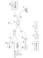
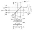
まず図1Aにおいて、本発明の教示を盛込んだ光学的コヒーレンス領域反射計(OCDR)10が示される。短いコヒーレンス長さ(広スペクトル帯域幅)光源12からの出力が、光結合器14に対して1つの入力として接続されている。このような結合は、望ましい実施例では光ファイバ経路16である適当な光経路を介して行われる。光源12は、例えば、発光ダイオード、超発光ダイオードまたは適当な波長の他の白光源でよく、あるいは短パルス・レーザでもよい。このような光源は、望ましい実施例では10μm以下のコヒーレンス1tを持つことが望ましい。後で述べるように、光源12のコヒーレンス長さはシステムの分解能を強化するため最小化されることが望ましい。
【0074】
結合器14に対する他の入力は、光ファイバ経路20を介して結合器に与えられる可視出力を生じるレーザ18からのものである。後で更に詳細に述べるように、レーザ18はシステムの正常な動作には寄与せず、ダイオード12からの光が赤外線領域にあり従って眼に見えない時、試料と適正に整合するように可視光の光源を提供するため用いられるに過ぎない。
【0075】
結合器14からの出力は、光ファイバ経路24を介して結合器22に対して入力として与えられる。結合器22において受取られる光即ち光エネルギは、走査/試料組立体28に至る第1の光ファイバ経路26と、基準組立体32に至る第2の光ファイバ経路30との間で分けられる。組立体28は、走査される試料における光経路26から受取る光を集束する1つ以上のレンズと、試料に対する光の横方向、横断方向または縦方向の運動を生じるための種々の機構とから形成されるレンズ組立体を含む。特に、望ましい実施例では、縦方向走査が基準組立体における運動により行われるが、試料またはプローブが縦方向、あるいは組立体28での他の方法で行われる縦方向走査のため移動されることもまた可能である。この組立体はまた、縦方向の走査位置と関連して焦点の縦方向即ち深さの位置を制御する機構も含む。組立体28のプローブ・モジュール部分は、患者の眼における走査およびイメージ形成あるいは測定の実行のため試料の外面に隣接して、例えば患者の眼に隣接して位置決めを行うように設計することもでき、あるいは例えば体内または他の経路を走査する血管内視鏡または内視鏡の一部として、試料の内部に定置するようにすることができる。図1Aの目的のため、走査および(または)イメージ形成される試料は組立体28内部に含まれる。本発明の色々な実施例により組立体28として機能する種々の機構が図3乃至図7に示される。
【0076】
全ての実施例において、プローブにより試料に対して送られる光は、プローブ・モジュールを介して再びファイバ26へ戻るように試料により反射される。経路26の光ファイバは、印加された電気信号に応答して振動(即ち、伸縮)して光ファイバの僅かな伸縮を生じ、これによりファイバを通る光信号を変調する圧電性の結晶トランスジューサまたはアクチュエータ34の周囲に巻付けられる。後で述べるように、この付加される変調は検出を容易にする。
【0077】
基準組立体32は、コリメーティング・レンズ36と、第1および第2の音響光変調器38,40と、コーナー・キューブ逆反射体42と、端部ミラー44とを含む。望ましい実施例では、コーナー・キューブ46は、このコーナー・キューブを光経路30と端部ミラー44の双方に対してあるいはこれから離れるように特定のパターンで往復運動させて試料の縦方向走査を行う機構46に取付けられる。後で更に詳細に述べるように、コーナー・キューブは均一な比較的高い速度(例えば、1cm/秒以上)で移動されて、ヘテロダイン検出を行うため用いられるドップラー・シフト変調を生じることが望ましい。キューブ42の機構46による運動の長さ即ち程度は、少なくとも試料における所要の走査深さの半分より僅かに大きい。機構46に対する走査パターンは、少なくとも走査が生じる部分において均一な速度Vを有することが望ましく、例えばランプ・パターンまたは鋸歯状パターンである。ランプ・パターンの場合は、測定またはイメージ形成はランプにおいて行われるが、両側で速度Vの鋸歯状パターンでは、走査は一方向または両方向にいずれかで移動するコーナー・キューブにより行うことができる。更に、係属中の出願で述べたように、回路の他の要素における適当な補償により正弦波または他の走査パターンを用いることができる。
【0078】
あるいはまた、縦方向即ち深さ次元における走査は、コーナー・キューブ42ではなく機構46の如き適当な機構により端部ミラー44を往復運動させることにより行われる。しかし、これが行われると、有効行程は50%減少されて、端部ミラー44は所定の深さ範囲を止めるに等しい経路によるのではなく前記範囲より僅かに大きい経路にわたって運動させられねばならないことになる。本例における端部ミラー44に要求されるより大きな移動行程は、達成し得る走査速度に悪影響を及ぼし、また変調ドップラー・シフト周波数を制限し、別の変調要素の使用を必要とする。機構46が完全に取除かれるならば、システムは端部ミラーが往復運動する時、ウォブルの結果生じる誤差の影響を更に受け易くなる。
【0079】
また、単一パス形態のためコーナー・キューブを配置することにより端部ミラーを取外すことも可能である。このような形態においては、コーナー・キューブに対する進入光がコーナー・キューブの頂点と整合される。この結果もまた有効行程の50%の減少を生じる結果となる。更に、先に述べたように、機構46は基準組立体32において取外すことができ、縦方向走査がプローブまたは試料のいずれか一方を縦方向に運動させることにより組立体28において行われる。このことについては後で述べる。これが行われるならば、コーナー・キューブ42は必要でなく、光経路30からの光は直接ミラー44に当たる。
【0080】
最後に、ドップラー・シフト周波数を用いる望ましい実施例の場合は、機構46がコーナー・キューブまたは端部ミラーを、先に述べたように走査範囲において実質的一定である速度で受けさせるが、これから述べるある実施例の場合は、縦方向におけるドップラー・シフト変調は用いられず主として所要の走査深さを制御するようにミラーの運動が生じる。このような実施例および他の実施例では、機構46は所要の走査深さを制御するため歩進状に動作する。
【0081】
結合器22と走査される試料の選択された深さ点との間の経路26の合計長さと、結合器22とミラー44間の経路30の合計長さとは、選択された深さ範囲の走査中試料の各深さ点に対して実質的に等しくしなければならない。更に、空間分解能を低下させるグループの速度分散を防止するため、経路26および30における光ファイバの長さもまた実質的に等しくなければならない。あるいはまた、グループ速度分散は、不均衡を補償するため既知のグループ速度分散と厚さの光学的物質を光経路に置くことにより等しくすることができる。例えば、基準経路におけるファイバが試料プローブにおけるそれよりも短いことを必要とする場合は、構成分散材料の長さを基準経路に含めることができる。このシステムにおいて使用される光ファイバの終端が反射を最小化し処理能力を最大化するため付角研磨および(または)反射防止コーティングが施されることもまた重要である。
【0082】
機構46は、変位機能を実施するための種々の装置のどれかでよい。例えば、機構46はステッピング・モータでよく、その運動が均等な速度が要求される実施例に対する平均化機構を介してコーナー・キューブ42またはミラー44に与えられる。DCサーボ・モータもまた、所要の運動を得るため使用することができる種々の電磁アクチュエータ、例えばスピーカ・コイルもまたこの機能のために用いることができる。このような電磁アクチュエータにより、必要な場所において均等な運動を生じるためにミラー位置の検出およびそのサーボ制御が要求される。更に、均等運動システムにおいて、ミラー移動経路の各地点における所要のミラー位置を示す信号を、実際のミラー位置の検出器からの信号、および運動するミラーを所要の一定速度に維持するようにアクチュエータを制御するため使用される結果として生じるエラー信号と対比することができる。機構46に対するサーボ制御検流計が駆動する直線的変位装置を使用することもできる。
【0083】
基準組立体32における1つのあり得る問題は、距離の決定精度に悪影響を及ぼすおそれがある変位されつつあるミラーの揺動である。このような揺動は、図1Aの実施例においてコーナー・キューブ42により部分的に補償され、このコーナー・キューブは一般にビームが入射する角度の如何に拘わらずビームが常にビームが入射した正確に同じ方向に戻るという特性を有する。当技術において公知の他の手法もまた揺動問題に対処するために用いることができる。
【0084】
組立体28および32から受取る反射は、それぞれ光経路26,30を介して光結合器22へ与えられる。これらの信号は結合器22において合成され、長さと一致する反射(即ち、基準経路長の差が光源のコヒーレンス長さより小さい場合の反射)に対する干渉縞を結果として生じ、この結果として得た合成出力が光ファイバ経路50に結合される。
【0085】
基準および試料光経路から戻る光間の干渉を最大化するためには、それらの偏光が実質的に同じでなければならない。この偏光の一致を確保するため、偏光コントローラが光経路26または30の1つに配置される。例示の目的のため、偏光コントローラ51が図1Aにおいて光経路30に示されている。このような偏光コントローラは、光ファイバ経路における偏光の変化を補償する。あるいはまた、所要の結果を達成するために偏光を維持するファイバおよび結合器をシステムにおいて用いることができる。更に、偏光が不規則に変化する用途においては、信号のフェージングを取除くために偏光の発散受取り装置をシステムにおいて用いることができる。このような偏光の発散受取り装置は当技術において公知である。
【0086】
光ファイバ経路50における光信号は、経路50からの光合成信号を対応する電流で変化する電気信号へ変換するフォトダイオード52に与えられる。フォトダイオード52からの出力線54における電流で変化する電気信号は、相互インピーダンス増幅器(TIA)55または他の適当な手段により電圧で変化する信号へ変換されることが望ましく、TIA出力は復調器56に対して入力として与えられる。
【0087】
本発明の教示を実施する際に種々の復調形態を用いることができる。その最も簡単な形態においては、復調器56は、合成出力信号の変調周波数付近を中心とする帯域通過フィルタ58と、エンベローブ検出器とからなる。このフィルタは、問題となる信号のみが探されて出力からノイズを除去することを保証する。このため、システムの信号対雑音比を強化し、これによりシステムの感度を強化する。フィルタされた信号は次にエンベローブ検出器へ与えられる。
【0088】
復調器56におけるエンベローブ検出器は、整流器62と以降の低域通過フィルタ64とからなる。この2番目のフィルタは、ベースバンド信号から高周波成分を除去する。復調器はまた、整流器の前後のいずれかにおける、ダイナミック・レンジ圧縮のための対数増幅器66をも含む。対数増幅器が使用されない場合は、対数圧縮はシステムのどこか他の場所、例えば処理用コンピュータで行われる。対数圧縮がなければ、境界からの強い反射がスケールオフするかあるいは弱い反射が眼に見えないかのいずれかである。
【0089】
先に述べた例示の復調器は、ヘテロダイン復調器の1形式である。しかし、当技術において公知である種々の他の復調器機能を実施するため使用することができる。
【0090】
回路56からの復調出力は、問題となる干渉エンベローブ信号である。種々の目的のための医者、技術者あるいは他の人員により使用されるこのようなアナログ信号の視聴覚的記録を得るため、適当なプリンタ68が使用される。望ましい実施例では、復調器56からのアナログ出力が、プリンタ68に加えあるいはその代わりに、アナログ/ディジタル・コンバータ70を介して所要のアナログ表示を行うようにプログラムされる適当なコンピュータ72へ送られる。1つ以上の記憶装置74がコンピュータ72に設けられる。コンピュータ72は、例えば、陰極線管モニターの如き適当な表示装置76上の復調された信号の表示を制御し、あるいは所要の記録を生じるように適当なプリンタを制御する。
【0091】
プリンタまたはコンピュータの表示を用いて走査されたイメージを再生する場合、走査イメージの濃度の如き特性はグレースケール・レベル(即ち、高い密度に対しては暗く、低い密度に対しては明るく)を用いて再生されるか、あるいは「類似カラー」イメージが特性を表わすカラー・スペクトルにおける青から赤のカラーで生成される。更に、コンピュータ72は、復調されたエンベローブ信号における種々の問題点を検出し、また測定を行いあるいはこのような検出に基いて他の有効な決定を行う。コンピュータ72は、適当にプログラムされた標準的なプロセッサでよく、あるいは特殊目的のプロセッサが所要の機能の一部または全てを実施するために提供される。
【0092】
ある実施例においては、図1Aに示されるOCDRが用いられ、コーナー・キューブ42が中間的であるが均一な速度で機構46により走査される。本論の目的のために、コーナー・キューブまたはミラーの運動により生じるドップラー周波数シフトが無視し得ないが、システムに対する主たる低周波ノイズに該当するに充分なだけ中間的な走査速度について考察する。ノイズ・スペクトルは、光源12、機械的構成要素および電気回路における変動の結果生じるノイズを含む。高い走査速度の時は、ドップラー周波数シフトが主な低周波ノイズより高くなる。ドップラー・シフト周波数fDはコーナー・キューブ42の変位から結果として生じ、コーナー・キューブの場合、式:fD〜4V/λにより与えられる。ここでVは、キューブが所与の時間に移動される速度、λは光源Nの光波長である。コーナー・キューブが使用されない場合は、fD〜2V/λとなる。このように、ミラーが変位される時、ウォブルを補償することに加えて、コーナー・キューブはまたドップラー・シフト周波数を倍増し、機構46の所与の速度Vに対する有効走査行程を倍増する。
【0093】
ドップラー・シフトがノイズの克服のため必要な帯域幅より小さい場合(ドップラー・シフト周波数が実質的にゼロであリ、歩進状の縦方向走査が行われる場合及び縦方向走査が行われない場合も含む。)、変調周波数を主たるノイズ・スペクトル以上にシフトさせるためには別の変調が必要とされる。図1Aにおいて、これは、圧電トランスジューサ34の使用により正弦波位相変調を生じることにより行われる。図1Aでは別の変調が試料経路26における発振器またはトランスジューサの使用により誘起されるが、このような変調は経路30においても生じることができる。端部ミラー44の相等する圧電変調もまた使用することができる。更に、圧電トランスジューサ34に加えて、このような付加的な変調に必要な小さな運動が、電磁要素、静電要素、または小さな略々正弦波形運動を生じるための当技術において公知の他の要素を用いて達成可能である。
【0094】
あるいはまた、図1Aに示されるように、このような付加的な変調は、音響光変調器(AOM)を介して光を基準アームおよび(または)試料アームに通すことにより達成可能である。このような変調器は、光ビームの周波数シフトを生じ、またこれによりビームをシフトするドップラー・シフトと略々等価である効果を生じる。このような音響光変調器は、ある場合には、ミラーまたはコーナー・キューブの運動の代わりに用いることができる。図1Aに示される如きバルク光学装置であり得、あるいは比較的小さな直線的光ファイバAOMでもよいAOMは、キャリヤ周波数を有効に増加させて高速度走査を可能にする。このような目的のためには1つのAOMで充分であるが、図1Aに示されるように2個のAOMを使用することができる。2個のAOMに対する理由は、AOMが通常はこのような用途に要求されるよりもはるかに高い周波数で駆動されること、検出周波数が2個のAOMを異なる周波数で駆動することにより所要の周波数へ下げられることであり、検出器の周波数は差の周波数であるためである。
【0095】
要素34から、あるいは光経路長さを変調する他の適当な手段からの付加的な変調は、周波数fMであり、この変調器の発振振幅は、ピーク・ピーク発振運動または光遅れの変化が光源12の波長λの略々半分であるように変化される。付加的な変調音響ドップラー・シフト周波数の合成結果は、出力エンベローブを変調周波数fD、fM+fD、fM−fD、およびfM±fDのより高い高周波にさせる。fMは通常はノイズ・スペクトルおよびアライアジング問題を克服するに充分な高さになるように選定される。
【0096】
光検出器54からの出力の復調は、通常は(fM±fD)および(または)(fM−fD)における。例示の目的ため、復調が(fM±fD)におけるものと仮定する。このため、帯域通過フィルタ58に対する中心周波数は、周波数(fM±fD)に対してセットされる。フィルタ58に対する帯域幅は、信号の拡張および歪みを避けるため、受取られる信号の半値全幅(FWHM)帯域幅の略々2乃至3倍でなければならない。低域通過フィルタ64の帯域幅は、典型的には帯域通過フィルタ58のそれと略々同じである。結果として生じるドップラー・シフト周波数が主たるノイズ・スペクトルよりも高くなるようにキューブ42が移動しつつある速度が充分に高い速度を有し、かつ横方走査が信号のアライアジングを生じないように充分に広い間は、変調器34,38,40の如き装置による付加的な変調は不要であり、このことは関わる広帯域の故に2次元または3次元の走査ではあり得ない。
【0097】
この点に対して論述した実施例では、キューブ42の走査は少なくとも走査間隔では一定速度であった。しかし、サーボ制御される一定速度の機械的装置により達成できない高い反復率での非常に高い走査の場合は、共振的に(正弦波形)駆動される機械的アクチュエータをキューブ42またはミラー44の駆動のために使用することができる。これらのアクチュエータは、機械的アクチュエータ・システムの共振周波数で電流磁気的または電磁気的に駆動することができる。正弦波形駆動を許容するために要するシステムに対する調整については、図1Cに関して後で論述する。あるいはまた、より高い速度の走査が要求される場合は、走査を行うために機械的手法の代わりに光電気的手法を用いることができる。例えば、光経路を変更するために音響光変調器または他の光電気変調器を用いることができる。しかし、このような装置は現在では高価であり、範囲が制限されており、従ってこのような装置はほとんどの用途に対しては選好されない。
【0098】
図1Bは、縦方向のレンジ情報が、光コヒーレンス領域反射法ではなく光周波数領域の反射法により得られる本発明の別の実施例を示している。同図では、また残りの図においては、共通の要素を示すため同じ参照番号が用いられる。要素が僅かに変更された前の図における共通要素を示すためにはプライムを付した番号が用いられる。
【0099】
図1Bは、当技術において公知の多くの方法の1つにおいて周波数変調可能なスペクトル的にコヒーレントな光源79を用いる光周波数領域反射計を示す。光源79は、信号発生器78により線形FMチャープの形態で周波数変調される。光源79からの出力は、図1Aに関して述べた同じ光経路を通って走査/試料組立体28および端部ミラー44に至る。光経路の長さの変化は縦方向走査の実施のため本発明の本実施例のために用いられないため、図1Aに示した基準組立体の残部は不要であり、変調器34,38および40もまた同様である。レンズ36の如きレンズは必要であるかあるいは不要である。
【0100】
組立体28における試料および基準ミラー44からの反射光は、光ファイバ結合器22において合成されて光経路50を経て広帯域光検出器52′へ送られ、ここでこれらの光は光学的に干渉する。広帯域光検出器52′および相互インピーダンス増幅器55′は、検出された信号を増幅するため使用される。検出された光干渉は、試料の反射と基準ミラー44からの反射との間で差の経路長さに比例するRF周波数を生じる。電気的プロセッサ81においてこのような周波数情報を空間情報へ変換する当技術において公知の種々の方法が存在する。これらは、逆フーリエ変換手法による波形レコーダの使用を含む。線形性、スペクトル・コヒーレンス、変調帯域幅および周波数偏差を確保することの要件およびその手法は全て当技術において公知であり、かかる手法は図1Bの実施例において用いることができる。プロセッサ81からの出力は、A/Dコンバータ70を用いてディジタル化され、図1Aに関して述べた方法でコンピュータ72により処理される。プリンタおよびディスプレイは、図1Aに示された実施例に対する如く、本発明の本実施例に対して提供される。適当な修正により、本発明の教示もまた線形的にチャープされた強さを修正した光源を用いて実施することができる。
【0101】
先に述べたように、アクチュエータ46が正弦波形または他の非線形速度特性を有する場合、ドップラー・シフト周波数fDはもはや一定ではなく、復調器56をこのキャリヤ周波数の変動に対応させねばならない。この目的を達成するための少なくとも2つの方法がある。いずれの場合も、図1Cにおけるシステム10Cに対して示した如く、出力線87がアクチュエータ46における位置センサから設けられる。簡単にするため、同図における基準組立体はアクチュエータ46により線方向に移動される端部ミラー44として示される。線87における電圧は、通常アクチュエータの位置、このためミラー44に対する位置の関数として変化するが、位置センサ出力もまた電流で変化する。センサがディジタル出力を生じるならば、線87はA/Dコンバータ70′を介することなくコンピュータ72に接続される。コンピュータ72で受取られる強さおよび他の入力が試料における走査位置と相関させられるようにアクチュエータ46′が非線形速度特性を有する時、線87における信号が要求される。このような相関関係は、位置が入力が受取られる時から決定できる線形走査では必要とされない。
【0102】
より簡単な手法では、帯域通過フィルタ58および低域通過フィルタ64に対する受入れ帯域が増やされて、ミラー44の正弦波形運動の大きな部分にわたりドップラー・シフト周波数fDにおける変動を許容する。これらの変動は、Vにおける変動と共にfDが直接変化する故に生じる。このように増やされた復調器の受入れ帯域幅は、ノイズの受入れの増加を導き、これにより低下した検出感度を結果としてもたらす。しかし、この手法は簡単であり、検出感度の要件が厳しくない場合に用いることができる。更に、受入れ帯域幅のこのような増加は、信号帯域幅ΔfFWHMが既にfDに対して大きい時は比較的小さく、この状態はコヒーレンス長さが非常に小さい時に生じる。
【0103】
図1Cは、復調周波数がスーパーヘテロダイン・システムを用いて瞬間的なドップラー・シフト周波数に動的に同調される第2の手法を示している。アクチュエータ即ち駆動機構46′におけるセンサは、電圧制御発振器95に与えられる前に利得回路91およびバイアス回路93により修正される線89における速度依存電圧を生じる。発振器95からの出力は、増幅器55を介して検出器52からの出力により回路97において乗じられる。VCO95に与えられる信号の利得およびバイアスは、乗算器97からの出力における変調周波数が帯域通過フィルタ58に対する中心周波数として選択される所要の中心周波数において実質的に一定であるように調整される。図1Aの実施例におけるように、フィルタ58の帯域幅はピーク信号の帯域幅の2乃至3倍にセットされ、線87における位置センサ出力の必要を除いて、検出および処理の残部は図1Aに関して先に述べたものと略々同じである。
【0104】
図1Dは、光ファイバではなくバルク光学系が用いられること、および異なる波長である2つの光源12Aおよび12Bを提供することにより空間特性を観察する能力が強化されることを除いて、図1Aと似たシステム10Dを示す。多数の波長オプションがバルク光学系の実施例に関して例示の目的のため示されるが、多数の波長もまた光ファイバの実施例で使用できかつ使用できることが望ましいことを理解すべきである。光源12Aおよび12Bは、異なる波長で動作するよう設計された同じ形式の光源でよく、あるいは異なる形式の光源でもよい。光源12Aおよび12Bからの出力は結合器60において組合わされ、その光出力は結合器59に与えられる。結合器59に対する他の入力は、レーザ18、例えばヘリウム・ネオン・レーザからの出力であり、その利得は整合目的のためにのみ使用される。結合器60および59は、例えば、2色ビーム・スプリッタ、偏光ビーム・スプリッタまたは通常のビーム・スプリッタでよい。
【0105】
結合器59からの出力は、ビーム・スプリッタ61および65へ与えられる。ビーム・スプリッタ61は、その入力の一部をレンズ36を経てミラー44へ与え、また光線をビーム・スプリッタ65へ通し、このビーム・スプリッタがこの光線をレンズ82を経て試料84へ与える。ミラー44からの反射は、レンズ36、ビーム・スプリッタ61およびミラー67を介して相互干渉結合器69へ与えられる。ミラー44およびレンズ36は、図1Cに関して述べた機構46′の如き機構により運動させられる変位段の一部である。先に述べたように、このような変位が主たるノイズ・スペクトルより下方のfDの如き速度で行われるならば、例えばミラー44を変調器75の制御下で振動させられる圧電クリスタル63へ取付けることもまた必要である。これを実施するための他の方法については先に述べた。試料84からの反射は、レンズ82およびビーム・スプリッタ65を介して相互干渉結合器69へ与えられる。
【0106】
結合器69からの出力は、整合目的のため使用されるCCDカメラ7へ与えられ、またレンズ73を介して光検出器52へ与えられる。検出器からの出力は、2つの別個の経路を介して与えられる。各経路は、所与の光源12に対するドップラー・シフト周波数fDと対応する中心周波数を持つ帯域通過フィルタ58を含む復調器56A,56Bを含んでいる。fDが光源の波長の関数として逆方向に変化するため、各復調器は適当な光源の波長と対応する信号のみを復調して、2つの光源波長から結果として得る出力を分けることを許容する。対応するA−Dコンバータ70を介して与えられた後、この2つの出力はコンピュータ72へ与えられて、これにより適当に処理される。
【0107】
あるいはまた、検出器52は各損失の波長に対応して設けられ、この場合各光検出器の前には適当な通過帯域を持つ適当な波長のみを伝送する光波長フィルタが設けられる。ビーム・スプリッタは、復調器を検出器出力側に置いて光波長フィルタの前に設けられる。
【0108】
図1Dおよび先の論議においては僅かに2つの個々の信号λが示されたが、このことは本発明に対する限定ではなく、より多数の光源および検出器(および(または)復調器回路)を適当な用途のため設けることができる。
【0109】
例えばシステム10Aまたは10Dの動作を説明する目的のため、試料84が人間または動物の患者の眼であると仮定しよう。測定が行われる時、重要である3つの整合が存在する。第1に、ビームは所要の角度で試料に進入するように試料に対して整合されねばならない。この角度は、通常は眼の層の角度と直角をなす角度である。第2に、ビームは問題となる試料領域上に側方に配置されねばならない。これは、ビームの側方位置の対照点である。最後に、ビームは眼における問題のレベルで集束されねばならない。これらの整合機能の各々を実施するため多数の手法が用いられる。
【0110】
特に、所要の入射角度を得るために多数の異なる手法を用いることができる。ビームが前記層即ち、反射される前に対して直角となる反射が一般に実質的に最大化されるため、整合を達成する1つの簡単な方法は、プローブ80、ビーム・スプリッタ65またはレンズ82および(または)試料(即ち、患者の眼)の位置即ち角度を調整することであり、基準アームを固定して試料からの反射を検出することである。このため、検出された反射のエネルギが最大となる整合は、所要の整合角度となる。通常は、この手法を用いて比較的迅速に所要の角度を見出すことが可能である。
【0111】
角度の整合を達成するための第2の手法は、基準アームが固定されないことを除いて第1の方法と似ており、通常の読みがシステムから行われると、整合は出力を最大化する整合が得られるまで手動により調整される。
【0112】
第3の方法は、ビームの整合を検出するためビームが反射される方向に見ることである。これを直接行うことは、特にファイバを用いる時に難しいため、このような決定は一般に、試料からビームの位置を測定することができるCCDカメラ71(図1D)の如き装置に対して反射されるビームの一部を指向するビーム・スプリッタを提供することにより行われる。この装置は、ビームが試料に対して適正に整合される時カメラにビームが当たる地点が決定されるように、最初にシステムにより較正される。次いで、動作において、先に決定された地点におけるCCDカメラにビームが当たる整合角度が得られるまで試料およびプローブを調整することができる。
【0113】
側方位置の整合は、この時手動により最もよく行われる。この操作を行うために、レーザ18が投入される。光源12は、この操作のためにはオンの状態でもオフの状態でもよい。レーザ18は、ビームが当たる眼の側方位置の狭いビームの視覚的表示を行い、次にビームが所要の位置に当たるまでプローブ・ビームまたは患者のいずれかの位置が手動により調整される。光源12からの光が可視帯域にあるならば、レーザ18は必要がなく、光源12からの光を整合のため使用することができる。
【0114】
読みを行うため用いられる集束円錐角が、できるだけ大きな開口数(円錐角)を持つことの要求度を、公報散乱または反射された光が有効にファイバ(あるいは、ファイバが用いられない場合他の光経路26)へ戻るよう接続されるフィールドの所要の縦方向範囲即ち深さが得られることに対して均衡化することにより決定される。大きな開口数は、試料面上の鉛直入射を生じるための、また戻る光線が広い立体角にわたり分散される後方散乱の測定のための角度整合の厳密さを緩和し、広い円錐角はファイバに対する結合を増す。しかし、大きな円錐角は縦方向の範囲を減少する。このため、開口数即ちFナンバーは、測定が行われるべき眼または他の試料における領域の縦方向の限度に等しい視野の深度と対応するように選定されるべきである。この論議の目的のために、視野の深度はファイバに対する背面結合効率が半分に減じる焦点面からの縦方向距離として定義される。
【0115】
他の整合における如く、試料および(または)プローブは、システムが試料内即ち眼の内部の所要の点に集束されるまで相互に移動される。レーザによる場合でも、焦点の視覚的決定は難しいため、含焦を行う望ましい方法は、例えばディスプレイ76上に得られる出力でシステムを操作することである。後で論議するように、このような出力におけるある高い振幅点は、特定の層または眼における移動を表わし、焦点はこの移動が走査における所要の点において生じるまで調整することができる。
【0116】
整合が一端行われると、システムは所要の測定を行うように用いることができる。このような測定を行うため、測定レーザ18がオフにされ、光源12がオンにされる。既にオンでなければ機構43または43′もまたオンにされて、キューブ、またはミラーの所要の運動を生じる。機構43,43′が充分に高い速度で運動しなければ、圧電変調器34または63をオンにすることも必要である。
【0117】
先に述べたように、光源12は、当たる低コヒーレンス長さがスペクトル的に広くなければならない。このため、略々10μmのコヒーレンス長さを持つ先に述べた形式の光源の場合は、10μmまでの空間的な分離、従って分解能が得られる。これは、他の現在入手可能な装置において得られるものよりもはるかに高い分解能である。
【0118】
経路の長さ26,30は、最初は試料28における所要の初期走査深さにおいて集束されるビームと等しい。ミラー44(または、キューブ42)がレンズ36から遠去るように移動されるに伴い、経路長さが等しい試料における点が試料内の連続的に増加する深さまで走査される。走行における各点において反射が生じ、光が通過する物質に対す屈折率およびかかる屈折率の境界域の関数である光の散乱が生じる。干渉縞は、試料における地点までの経路長さ(LS)と電流ミラーの位置までの経路長さ(Lm)との間の差が光源のコヒーレンス長さ(CL)より小さい(即ち、LS−Lm<CL)試料における深さ点に対して生じる。従って、光源のコヒーレンス長さが得られるシステムの分解能を決定する。これは、コヒーレンス長さをできるだけ小さく保持する理由である。
【0119】
結合器22または69からの干渉出力は、このように試料内の特定深さで得られる反射または散乱を表わす。走査中に得られる連続的な干渉計出力は、走査深さにおける媒体の散乱特性に従って、反射が通常最大となる試料内の光学的接合点におけるピーク値を持ち、予め定めたパターンにおけるある小さいピークを持つ図2Aに示されるものの如きエンベローブ信号を形成する。
【0120】
ミラーが速度Vで走査されつつある時、周波数fD〜2V/λ(コーナー・キューブが移動される図1Aの場合は、〜4V/2)を有するドップラー・シフト周波数は、図2Bにおける強さの出力の小さな部分について示される如くエンベローブ信号に重ねられる。但し、Vはミラーが移動される速度、λが光源12の波長である。図2Cは、復調後のこの同じ出力部分を示している。
【0121】
先に示した式から、ドップラー・シフト周波数が光源12の波長に依存することが判る。このため、2つの別個の光エネルギ源12Aおよび12Bが提供される図1Dに示した実施例の場合は、結合部69からの干渉計出力は異なる波長における吸収および反射における差の関数である2つの個々のエンベローブを含み、各干渉出力が異なるドップラー・シフト周波数で変調されることになる。このため、先に示したように、各復調器56における帯域通過フィルタ58は、ドップラー・シフト周波数の別の1つに対する中心周波数および帯域幅を持つように選択され、あるいは多数の検出器による光の濾波が用いられてこれら2つの信号の検出および分離を可能にする。
【0122】
2つ以上の異なる波長における干渉計検出を行うことができることは、特異な利点を提供する。これらの利点は、種々の試料素材の吸収、反射および他の光学的特性が波長と共に変化するという事実から起生する。このため、2つ以上の波長における測定を行うことにより、波長に依存する吸収および散乱の如き試料の光学的特性のスペクトル特性を許容する。特に、後方散乱の対数減衰率は、異なる物質に対しては異なり、ある所与の物質では、波長と共に変化し得る。物質からの異なる波長における後方散乱パターンを観察することにより、またおそらくは試料の層からの後方散乱または反射減衰の平均率を観察することにより、この層の物質に関する情報または種々の物質特性が得られる。種々のスペクトル特性の測定は、それ自体が問題となり、また2つの試料層、例えば類似する光学的特性の故に1つの波長測定では弁別することが通常は困難である2つの組織層の間を弁別するためにも使用される。特に、不整合の如き見かけ上の効果は、境界を更に容易かつ正確に識別することを可能にするように補償される。基本的には、このような境界は、絶対値ではなく比で調べることにより識別される。
【0123】
図3Aは、図1A〜図1Bの組立体28に対する1つの比較的な実施例を示す。この実施例では、ファイバ26はプローブ・モジュール80で終る。このプローブ・モジュールは、1つ以上のイメージ形成レンズを含み、ファイバ26の出力と走査される試料84との間に位置された1つのレンズ82が図に示されている。適当な線形変位段または他の機構86が、2次元走査を行うためプローブ・モジュール80を試料84に対して横断方向または側方に移動させるように接続される。同様な機構(図示せず)が、試料84の3次元走査を行うためプローブを横断方向または側方の前記とは別の方向に移動させるため設けられている(以下本文においては、時に横断方向および側方走査はまとめて横断方向走査と呼ばれる。)。機構86は、ステッピング・モータあるいは他の適当な位置決め機構であり、コンピュータ72は(図1)によるか、あるいは試料84における走査の位置がコンピュータにより知られるようにコンピュータ72に位置決め情報を提供する位置決めコンピュータにより制御されることが望ましい。あるいはまた、プローブ・モジュール80は静止状態のままであり、試料84は矢印88で示される如く所要の多次元走査を行うため1次元または2次元で変位することができる。更に、先に述べたように、プローブ・モジュール80または試料84は、走査のための縦方向位置を生じるように適当な変位機構により縦方向に移動することができる。これは、コーナー・キューブまたは端部ミラーの移動の代わりにあるいはこの移動と関連して行われることになる。
【0124】
図3Bは、プローブ・モジュールが第1のコリメーティング・レンズ90と、時に瞳孔面と呼ばれる面内の1つ以上の軸の周囲に検流計または他の適当な機構100により回転することができる変向ミラー92と、2つの別の集束レンズ94,96とを含む本発明の別の実施例を示している。この試料は、眼84′として示される。図3Bでは、焦点は眼84′の後方またはその付近にあり、ビームは、、ミラー92が枢軸98および(または)これに直角をなす枢軸の周囲で機構100により回転させられる時、眼の背面に沿って異なる地点を走査するため略々接眼レンズの位置における眼のノード点の周囲に枢動させられる。この場合もまた、ミラー92の位置は適当な方法でコンピュータ72に対して通信される。
【0125】
更に、先に述べたように、コーナー・キューブ42が機構46によって移動される時、検出が生じる眼84′における縦方向または深さ地点が変化させられる。しかし、図3Bに示されるように、眼における光ビーム102に対する焦点深さは一定のままである。このため、所与の深さの走査の多くは、ビーム102が読取りが行われる地点に対して焦点が外れる。この問題を克服するため、走査機構46と同期されかつ集束レンズ90を光が通る方向と平行な方向に移動させる走査機構104が提供される。これは、試料84′におけるビーム102に対する焦点深さにおける変化を生じる。ドライブ46および104が同期されると、眼84′におけるビーム102の焦点は、各時点において眼で走査される地点と実質的に等しくさせることができ、測定およびイメージ形成のための最適の解決法を提供する。焦点を縦方向に変更するための技術において公知の他の手法もまた、焦点と検出を同期させるために用いることができる。
【0126】
図3Bにおいて、1つの瞳孔面内で1つまたは2つの横断方向次元で走査が行われる。図3Cは、2つの1軸走査ミラーが用いられ、別の走査ミラー106が第2の瞳孔面内に設けられ、このミラーが検流計または他の適当な機構110により軸108の周囲でミラー92の回転方向に対して直角の方向に走査される。ミラー106から反射された光は、レンズ112,114を通って眼84′の開口を通過して眼における選定された焦点に達し、この焦点は3次元で変化し得る。図3Bおよび図3Cにおけるこの検流計で駆動されるミラー92および106は、回転する多角形ミラーまたは他のビーム指向装置により置換することができる。先に述べた実施例における如く、位置に関する情報は、適正なイメージ形成および処理を可能にするためコンピュータ72へ通信される。
【0127】
図3Dは、組立体25の更に別の実施例を示し、これにおいては、瞳孔面内のミラー92が適当な回転運動機構95により軸93の周囲に回転させられ、またそのピッチがピッチ変更機構97により変更される。その結果、眼84′の円形走査を生じ、円の大きさ(即ち、直径)がミラー92のピッチ角に従って走査される。図3Dの構成は、例えば、患者の眼の感光神経頭の周囲を走査するため用いることができ、この走査は2次元走査を提供するように処理される。機械的な指向機構について先に述べたが、当技術において公知である光電指向機構もまた用いることができる。
【0128】
図4Aおよび図4Bは、組立体28に対する更に別の実施例を示し、これにおいては、ファイバ26が枢着点103を介して静止ハウジング105に取付けられる鞘部101に埋設される。鞘部101はハウジング105に固定された機構107上に静置し、この機構は例えば圧電クリスタル、ステッピング・モータ、電磁アクチュエータ、静電アクチュエータなどでよい。機構107が鞘部101を移動させるに伴い、ファイバ26の先端部は横方向に移動させられる。この運動は、眼84′における固定された進入点(図4A)の周囲で付角走査、従って眼の焦点面における横方向走査か、あるいは試料84の如き試料(図4B)に沿う横方向走査のいずれかにレンズにより交換される。レンズ109は、縦方向走査を制御するかあるいは試料84における集束を図1A〜図1Bに関して前に述べた方法の1つにおいて行われる縦方向走査と同期させるため、図4Bにおける縦方向に運動し得る如く示される。必要に応じて、枢動部103は取除くことができ、その結果鞘部101は、ある角度方向に運動する代わりに機構107の動作の結果として上下に直線的に運動する。
【0129】
図5は、プローブ・モジュールが、血管、食道などの如き管状構造120のイメージ形成を行うために使用される血管内視鏡または内視鏡の一部である別の実施例を示している。ファイバ26の遠端部は、外側鞘部124の内部に回転自在に支持される内側鞘部122に埋設されている。内側鞘部122は、ファイバ26の遠端部に形成されたレンズ126を有し、外側鞘部124の端部を越えて延長する付角ミラー面128で終わっている。プローブ・モジュール121は、血管壁を1次元で走査するため、血管壁120に沿って(即ち、矢印130の方向に)側方に手動あるいは適当な駆動機構により移動させられ、一部をなすミラー128を含む内側鞘部122は2次元で血管壁を走査するため外側鞘部124に対して回転させることができる。機構46の制御下でのコーナー・キューブ42の連動は、血管壁の深さ次元での走査を生じて3次元走査を行い、あるいは深さ次元におけるかかる走査は先に述べた手法の1つによって達成される。図5に示される実施例の場合は、経路26に対して所要の等しい長さを維持するためには、プローブ・モジュール121が血管壁に沿う方向130で実質的な距離だけ移動するため、ファイバ26は最初ある量の弛みを与えることができ、あるいはこの方向の運動を許容するためカール即ちコイル状にすることもできる。
【0130】
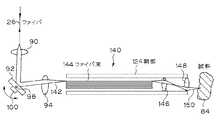
図6に示される内視鏡プローブ140は、ファイバ26の遠端部のレンズ90と、検流計で制御するミラー92と、図3Bにおける対応する要素と同じ方法で機能し略々同じ機能を生じる集束レンズ94とを有する。レンズ94からの出力ビーム142は、光ファイバ束144における1本以上の単一モード光ファイバに与えられる。ビーム142が与えられるこの光ファイバ束144は、ミラー92の走査位置に依存する。ファイバ束144の遠端部では、束144からの出力がレンズ146,148をへて試料84へ送られる。試料84における走査ビーム150の横方向位置は、ビーム142が与えられる束144におけるファイバと共に変化し、このためミラー92の位置と共に変化する。ビーム150は、このように、ミラー92の回転により試料84を横切って直線的に走査される。ミラー92が2次元で走査されるか、あるいは図3Cの3次元走査機構のレンズ112からの出力がレンズ94からの出力の代わりに用いられ、光ファイバ束144が1次元ではなく2次元にファイバを有するならば、ビーム150は試料84の表面を横切って2次元パターンで走査させられて、3次元走査を行うことを可能にする。
【0131】
図7は、本発明の教示を用いて構成される更に別の内視鏡プローブ・モジュール160を示す。本例では、ファイバ26の遠端部はばね162により鞘部124の内壁部に接続されている。ばね162は圧電トランジューサ164、あるいは鞘部124の壁部に沿って延びる電線166によりドライバ168に接続される当技術において公知である電磁アクチュエータ、静電アクチュエータまたは他のアクチュエータ上に装置してこれにより振動させられる。ファイバ26の横方向運動は、屈折率が変化するレンズ(GRINレンズ)または他の適当なレンズ172に与えられる光ビーム170の対応する横方向運動を生じる。レンズ172からの出力光ビームは、試料84の横方向走査を生じる。
【0132】
血管内視鏡/内視鏡プローブの3つの異なる形態が図5乃至図7に示されるが、本発明の教示を用いて他の血管内視鏡/内視鏡プローブ・モジュールに内側または外側の光学系を設け、ファイバ自体または外側レンズまたはミラーの運動を与え、また用途の応じて異なる走査パターンを用いることができる。
【0133】
先に述べたように、本発明の種々の実施例に対する典型的な走査パターンは、プローブ組立体を試料に対して選択された横方向位置に配置させ、図1A〜図1Bに関して述べた機構46または他の縦方向走査機構を所与の横方向位置における縦方向または深さ走査を完了するように動作させることである。この横方向位置は、例えば図3〜図7に関して述べた方法で変更され、深さ走査は、新たな横方向位置で完了される。このプロセスは、全ての所要の横方向位置で走査が行われるまで繰返される。これは、図8Aに示される走査パターンである。
【0134】
しかし、図8Aに示される走査パターンは高速の縦方向走査を必要とする。先に述べたように、ある実施例においては、この縦方向走査は、回路56(図1A)において復調することができる均一なドップラー・シフトを生じるためには、一定速度におけることが望ましい。しかし、非常に高速の一定速度走査は達成が難しい。従って、横方向走査のための一定速度に関する要件が比較的少ないため、また共振するように駆動される検流計またはファイバ反射器を横方向走査の非常に高い速度を生じるため、図8Bに示される如き走査パターンは、特に大量の横方向点がイメージに対して用いられる時に望ましい。図8Bにおいて、完全な横方向走査が縦方向位置毎に行われる。換言すれば、例えば図3Aによれば、機構86は機構46(図1A)の各位置毎に完全な1サイクルを実施することになる。このような走査パターンでは、機構46は連続的に回転させられるのではなく歩進運動させることができる。
【0135】
図8Cは、本発明の教示の実施において用いられる更に別の走査パターンを示す。この走査パターンでは、試料における縦方向位置が、例えば端部ミラー44の位置を選択された位置へ歩進させることにより前に述べた縦方向の位置決めのための手法の1つを用いて制御され、次いで試料におけるこのような深さ即ち縦方向位置において縦方向の1次元または2次元で走査が行われる。一旦このような走査が完了すると、走査は同じ深さで反復されるか、あるいは縦方向位置の制御が以降の走査を異なる深さで行わせるように歩進状に進められる。角深さレベルにおける走査が1次元ではなく2次元で行われ、このような2次元走査が全ての選択深さではなく1つ以上の選択深さでのみ行われることを除いて、この3次元走査が図8Bのそれと似ていることに注意すべきである。
【0136】
以上の記述において、横方向次元における走査パターンは直線を用いて行われる必要がない。湾曲即ち円形走査パターンは、湾曲しない特定面に沿って深さおよび断面のイメージ情報を得ることが要求される場合に用いられる。図3Dおよび図5の走査実施例はこの点を示している。
【0137】
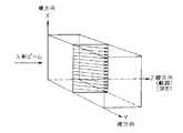
ここまで述べてきた本発明の実施例におけるあり得る1つの難しいことは、試料の完全な2次元または3次元走査がかなりな期間を要することである。これはある機械的または半導体試料の如く時間と共に変化しない試料に対しては受入れられるが、時間と共に急速に変化する生物試料に対しては受入れられない。図9は本発明の別の実施例を示し、この実施例ではこの問題は、多数の光源12A〜12Cおよび多数の検出器52A〜52Cを用いるが1つの可動基準ミラー44′を用いて試料を並行に走査することにより克服される。各光源12A〜12Cに対しては個々の光源が提供され、あるいは1つ以上の光源からの光線が所要数の光源を提供するため分けられる。同様に、多数の基準点が設けられる。多数の検出器52A〜52Cからの出力は、コンピュータ72へ与えられる前に特殊な処理回路180により処理される。少数の並行走査が行われる場合は、このような光源を側方に走査ことも依然必要であろう。例えば、図9における試料84に与えられる各ビームもまた3次元の走査を行うように図に対して出入りする方向に走査することもできる。あるいはまた、並行走査は3次元で行うこともできる。電子的処理回路180の容量が充分であるものとして、ビームの別の側方または横方向走査が必要でないように、2次元または3次元における充分な回数の並行走査を行うことができる。並行走査はまた、図1Bの走査技術を用いて行うこともできる。
【0138】
図10は、過大な強さのノイズが存在する場合に用いられる1つの可能な均衡された受信機の実施例を示している。この実施例では、2個の光検出器52Aおよび52Bが過大な強さのノイズを除去するため当技術において公知の方法で用いられ、このノイズは減算回路182において打消される。本例では、試料およびコーナー・キューブ42の2面からの反射から入力を受取る別の光結合器184が提供される。均衡化された検出を行うための当技術において公知の他の多くの技術もまた使用される。図10に示される本発明の実施例の動作は、他の点では例えば図1Aに関して述べたものと同じものである。
【0139】
横方向走査パターンを有する実施例においてあり得る問題は、これら実施例が必要とする高い横方向走査速度では、使用される信号帯域幅が非常に大きいため、この信号のアライアジングがイメージに生じ得ることである。信号のアライアジングは、例えばドップラー・シフト周波数(fD)で変化し得る所与のイメージに対するイメージ強さにおける変動を含む。このようなアライアジングの1つの補償方法は、1つの試料において多数の走査を行い、各走査の結果をメモリー74に格納して、コンピュータ72において種々の走査からの値を平均化してアライアジングの変動を取除くことである。アライアジングを取除く他の望ましい方法は、先に述べた手法の1つを用いて信号帯域幅より高い変調を得ることである。
【0140】
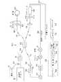
図11は、複屈折を検出するため偏光を用いる本発明の別の実施例を示す。本発明のこの実施例では、光源12からの光が、偏光を含む(高い複屈折の)ファイバ194へ与えられる前に、1対のレンズ192間に挟持された偏光器190において偏光される。例示の目的のため、偏光器190は光源12からの光を縦方向に偏光する如く示され、縦方向の偏光はファイバ194のモードの1つである。ファイバ194は、偏光を含むファイバ198,200に対して縦方向に偏光された光を出力する偏光を含む結合器196に結合される。ファイバ198は集束レンズ202で終り、このレンズからの光出力は4分の1波長遅延プレート204を介して試料84′へ与えられる。プレート204は、円偏光された光が試料84′に入射するように配置され指向されたゼロ次または低次のプレートであることが望ましい。試料の複屈折が存在しない場合は、プレート204はこれを通してファイバ198へ進む反射光を横方向偏光に変換する。偏光に従って光を異なる速度で層に伝搬させる試料の複屈折が存在する時は、複屈折を生じる試料構造を呈しあるいはこれにより深い試料層から反射された光は、一般に楕円偏波状態でファイバに戻ることになる。
【0141】
基準アームにおいて、ファイバ200における縦方向に変更された光はレンズ202および4分の1波長遅延プレート210によりミラー44に対して集束される。これもゼロ次または低次であることが望ましいプレート210は、ミラーに与えられる光が楕円偏波され、ファイバ200へ戻されるミラーからの反射は等しい横方向および縦方向成分を持つ直線偏波状態にあるように配向される。試料および基準反射は結合器196において干渉縞と再び合成されて偏光を含むファイバ212へ与えられる。ファイバ212は、偏光ビーム・スプリッタ216に向いたレンズ214で終わり、ビームスプリッタからの横方向に偏波された光は検出器52Cへ与えられ、ビームスプリッタからの縦方向に偏波された光は検出器52Dへ与えられる。レンズ214および偏光ビーム・スプリッタ116は、ファイバ偏光ビーム・スプリッタにより置換することができる。
【0142】
共に同じドップラー・シフト周波数にある2個の検出器により検出された干渉信号は、復調器56とA/Dコンバータ70において個々に処理されて(個々の復調器およびA/Dコンバータは図11に単一のユニットとして簡略に示される)2つの干渉信号と、1つの横方向振幅成分11と、1つの縦方向振幅成分12を生じる。これらの信号は、コンピュータ72へ与えられ、ここで試料光経路における周回複屈折遅延φ
【0143】
【数1】
を決定するために、また試料反射のための振幅|lt|
|It|=|I1|2+|I2|2
を決定するために使用することができる。
【0145】
このように、2つの検出器出力の相対的振幅および位相を測定することにより、試料の主軸に沿った相対位相の遅延についての情報が試料の深さの関数として得られる。
【0146】
複屈折は、網膜の神経繊維層の如き眼における構造、ならびに他の高次の生物組織、水晶体および他の構造物において観察される。10乃至20μmの眼の神経繊維層の厚さにおける変化は緑内障における著しい間隔の変化であり得、また感光神経頭の放血および他の視野の喪失の進行を予見することができる。網膜の厚さを測定するための従来技術の手法は、単に40μm程度の分解能を持つに過ぎなかった。しかし、図11に示される装置は、10μmの分解能で複屈折を生じる網膜神経繊維層の厚さを検出することができる。網膜神経繊維層(RNFL)の内部からの後方散乱は、RNFLの内部からの後方散乱の屈折の遅れが他の複屈折面に対する深さと共に増加する故に、識別することができる。複屈折の遅れが変化する深さの範囲はRNFLの厚さであり、複屈折の遅れの変化率(RNFLの厚さで除した全遅れ)はRNFL内部の神経軸系密度の測定値を提供することができる。RNFLより深い層からの後方散乱および反射は、一定料の複屈折遅れを得ることになる。
【0147】
このような神経繊維層の測定を行う能力は、緑内障の早期の検出および緑内障の損傷の進行の客観的な評価に顕著な利点を提供する。このため、網膜構造からの弱い後方散乱信号を測定することができると共に、網膜の全厚さのみならず構成する下位層の厚さの直接的な検出もまた生じることが可能である。
【0148】
後方散乱光もまた、動脈斑および正常な動脈壁の如き最初の数mmの混濁組織試料から検出するも可能である。図12A〜図12Cは、正常な動脈壁と色々な種類の斑が沈着したものから得た後方散乱パターンを示している。後方散乱に対する対数減衰率もまた動脈壁に対するよりも脂肪斑に対して異なり、斑を弁別する別の方法を提供する。図5〜図7に示した形式の光ファイバ・プローブは、レーザ血管形成術および砕石術において使用される高解像度イメージを提供するため所要の場所に内視鏡の使用により送ることができる。これは、意図的でない血管の損傷および破裂の危険を低減することにより、このような処置の可能性を高めることになる。これは、この技術が従来技術の超音波法で得られるよりも微小な分解能を提供することができる許りでなく、動脈斑および正常な動脈斑を弁別する能力を、複屈折およびスペクトル特性の測定を含む多くの方法で提供する故である。動脈の内部の弾力に富む網膜は複屈折を高度に生じるが、その斑はそうではない、斑はまた他の異なるスペクトル特性を呈する。このような差別は、超音波法では容易に得られない。
【0149】
更に、特定の光ファイバおよびバルク光学系の構成を示したが、本発明が他の光学的構成を用いて実施することもできること、および機能の実施のため示した特定の装置における他の変更が用途に応じて可能であることが明らかである。このため、本発明については本文において遷好された実施態様に関して特に記述したが、形態ならびに細部における上記および他の変更が、本発明の趣旨および範囲から逸脱することなく当業者により可能である。
【図面の簡単な説明】
【図1A】本発明の望ましい実施例による光コヒーレンス領域反射計の概略ブロック図である。
【図1B】周波数変調された光源を用いる本発明の別の実施例の概略ブロック図である。
【図1C】本発明の別の光ファイバ実施例の概略ブロック図である。
【図1D】分解能を強化するため2つの別個の波長の使用を示す本発明のバルク光学系実施例の概略ブロック図である。
【図2A】図1の実施例を用いて得られる走査出力の特性を示すグラフである。
【図2B】エンベローブが重ねられた変調周波数を示す図2Aに示した如き出力波形の一部の拡大グラフである。
【図2C】復調後の図2Bの波形のグラフである。
【図3A】多次元走査を達成するプローブ・モジュールの一実施例を示すブロック図である。
【図3B】2次元または3次元走査を実施するための別のプローブ・モジュールの図である。
【図3C】3次元走査を達成するための別のプローブ・モジュールの図である。
【図3D】円形走査を行うための別のプローブ・モジュールの図である。
【図4A】多次元走査を実施するための別の2つのプローブ・モジュール実施例の図である。
【図4B】多次元走査を実施するための別の2つのプローブ・モジュール実施例の図である。
【図5】内視鏡プローブ・モジュールの一実施例の断面側面図である。
【図6】内視鏡プローブ・モジュールの第2の実施例の断面側面図である。
【図7】内視鏡プローブ・モジュールの第3の実施例の断面側面図である。
【図8A】本発明の教示による試料の2次元走査のための第1の走査パターンを示す図である。
【図8B】本発明の教示による試料の2次元走査のための第2の走査パターンを示す図である。
【図8C】本発明の教示による試料の2次元走査のための第3の走査パターンを示す図である。
【図9】平行走査の実施例の概略ブロック図である。
【図10】平衡型レシーバの実施例の概略ブロック図である。
【図11】偏光を用いて複屈折を検出する本発明の別の光ファイバ実施例の概略ブロック図である。
【図12】図12A乃至図12Cは、それぞれ正常なもの、脂肪性斑点を含むもの、およびカルシウム沈積硬化した斑点を含むものである人間の大動脈を走査するため各図に示された如き実施例を用いて得られる図である。
【符号の説明】
10 光学的コヒーレンス領域反射計(OCDR)
12 光源
14 光結合器
16 光ファイバ経路
18 レーザ
20,24,26 光ファイバ経路
22 結合器
28,32 組立体
34 アクチュエータ
36 コリメーティング・レンズ
38,40 音響光変調器
42 コーナー・キューブ逆反射体
44 端部ミラー
46 機構
50 光ファイバ経路
52 フォトダイオード
54 出力線
56 復調器
58 帯域通過フィルタ
62 整流器
64 低域通過フィルタ
66 対数増幅器
68 プリンタ
70 アナログ/ディジタル・コンバータ
72 コンピュータ
74 記憶装置
76 表示装置
80 プローブ[0001]
BACKGROUND OF THE INVENTION
The present invention relates to a system, method and apparatus for forming an optical image that includes using an image to make high precision measurements in biological and other samples.
[0002]
[Prior art]
There are many industrial, medical and other applications where high resolution (generally 10 μm or less) images and measurements of distance, thickness and optical properties of biological or other samples are required.
[0003]
Current techniques for performing such measurements include coherence domain reflectometer (OCDR), optical time domain reflectometer (OTDR), ultrasonic scanning laser microscope, scanning confocal microscope, scanning laser ophthalmoscope, and optical Includes triangulation. Existing OCDR systems typically do not have the rapid data acquisition rate required for measurement of biological or other samples with kinetic kinetic energy, but OTDR systems are very expensive, It has only limited resolution and dynamic range.
[0004]
Probably the most commonly used technique, ultrasound is used to achieve the required acoustic impedance matching and thus avoid beam loss and distortion for applications such as making measurements in the human eye. Further, it is disadvantageous in that a contrast is generally required between the ultrasound head or probe and the object or patient being scanned. Such a contrast is not an issue when, for example, a scan is performed on the patient's chest, but such a probe may be used to measure intraocular distance to calculate the strength of the lens implant. When used to make measurements, it can cause severe pain to the patient.
[0005]
The relatively long wavelengths used in ultrasound also limit spatial resolution. In addition, ultrasound relies on various ultrasonic reflection and absorption characteristics to discriminate and allow recording or display of tissue or other problematic boundaries. Therefore, it is difficult to recognize such boundaries when the acoustic properties of adjacent layers to be measured are not significantly different.
[0006]
Scanning lasers or confocal microscopes and scanning laser ophthalmoscopes (SLOs) provide highly spatially resolved images that can produce real-time video images of the eye with a lateral resolution of, for example, a few μm. However, the resolution of the depth of the SLO decreases rapidly as the numerical aperture decreases. For example, SLO measurement of the retina through the pupil opening limits depth resolution to approximately 200 μm. SLOs are also expensive, reaching tens of millions of yen (hundreds of thousands of dollars).
[0007]
Optical triangulation provides slightly higher resolution but requires parallel boundaries. Such devices also have a relatively low signal-to-noise ratio, reducing resolution at relatively large depths, in which case the numerical aperture is limited.
[0008]
Accordingly, there is a need for improved methods and apparatus for performing high resolution measurements, particularly for performing such optical measurements, and this improved technique can contrast the object being measured. It is not required, maintains a substantially constant high resolution over the scanning depth in question regardless of the aperture size obtained, and is relatively compact and inexpensive to manufacture. Such systems can also discriminate between sample layers, identify layer materials or selected properties thereof, and provide 1D, 2D and 3D images of the scanned object. And must be sufficiently rapid for use in biological and other applications where the sample being measured varies over a relatively short time interval. Finally, it is desirable that this technique can provide information regarding the birefringence and spatial properties of the sample.
[0009]
In addition, there is a need for means for performing scanning of a sample in at least one lateral direction, along with scanning capability in the longitudinal direction. Further, particularly in medical applications, such a scan may be performed using a vascular endoscope or endoscope inside a tube or other structure such as a blood vessel, lung bronchus, digestive tract, genital tract or urinary tract. Often desirable. In order to perform such a scan, a probe that can be attached to an endoscope or vascular endoscope for performing an internal scan must be provided.
[0010]
Typically, the scan is completed over a full depth range at a given lateral and / or longitudinal position before shifting to the next position, which is more than the capabilities of the existing device. Requires scanning of mirrors or other elements used to perform a longitudinal range or depth scan at speed. This is particularly relevant when the longitudinal scan produces a Doppler shift frequency that affects the interference signal frequency and thus the sensitivity of the system. Therefore, it is required that such scanning is performed at a constant speed. However, it is difficult to achieve a very fast longitudinal scan at a constant speed where a two-dimensional or three-dimensional scan is performed, so other scan patterns are required. Further, in some applications, it may be desirable to perform a one-dimensional or two-dimensional lateral scan at a selected longitudinal position or depth.
[0011]
Another problem that becomes particularly acute when longitudinal scanning is performed is that the bandwidth of the received signal increases beyond the inherent Doppler frequency shift of the system. In such cases, aliasing (ie, variation in image intensity) can occur. Accordingly, it is desirable to provide a technique that enhances resolution by eliminating or averaging such intensity variations.
[0012]
Another problem with conventional systems is that if the scan is performed over an extended depth range, a smaller numerical aperture must be used to increase the depth of focus. However, this reduces the received optical signal energy over the lateral resolution and range. Accordingly, there is a need for techniques that allow the use of large numerical apertures over an extended depth range in the sample.
[0013]
In addition, the problem described in the text resulting from performing a longitudinal scan by mechanically moving a mirror or other element is that this scan can be performed electronically, e.g. This can be overcome by changing the amplitude. However, for certain applications for imaging dynamic biological samples such as the eye, the scanning speed required to perform a three-dimensional scan is such that a parallel manipulation method is desirable or required. It is.
[0014]
As described above, an improved optical coherence region reflectometer (OCDR) optical imaging and measurement system, or other imaging and measurement system, particularly selected or extended longitudinal or internal samples. There is a need for electronically scanned systems that are capable of performing one-dimensional, two-dimensional and three-dimensional scanning and measurements with sharp and high resolution and sensitivity over a direction or depth range.
[0015]
[Means for Solving the Problems]
The invention of claim 1
A light source that generates a beam of light having a short coherence length;
A reference path coupled to the light source, including an optical path length changing device, and including a first optical fiber;
An optical element coupled to the light source, including an optical element for focusing the beam into the eye, further including a probe module including optical scanning means for scanning the beam in the eye and including a second optical fiber A sample path;
Beam combining means for combining the light changed by the optical path length changing device and the reflected light from the eye to generate a combined light output;
A detector optically coupled to the combined light output to produce an output signal corresponding to the interference response;
A processor connected to the optical path length changer and detector to process the output signal and obtain an image of the internal structure of the eye, wherein the optical path length changer is in the eye from which image formation information is obtained. A processor that changes the vertical range of the
A system for forming an optical image in an eye is provided.
[0016]
The invention of
[0017]
According to a third aspect of the present invention, in the system according to the second aspect, the image includes a variation corresponding to a variation in the density in the eye.
[0018]
According to a fourth aspect of the present invention, in the system according to the third aspect of the present invention, the change in the image is expressed by the change in the gradation.
[0019]
According to a fifth aspect of the present invention, in the system according to the third aspect, the image variation is represented by a color variation.
[0020]
According to a sixth aspect of the present invention, in the system of the first aspect, the light from the light source is coupled to the third optical fiber, and the beam is split into the sample path and the reference path by the optical fiber coupler. Features.
[0021]
A seventh aspect of the invention is characterized in that, in the system of the sixth aspect, the optical fiber coupler also functions as a beam combining means.
[0022]
The invention according to claim 8 is the system according to claim 1, characterized in that the optical scanning means includes at least one movable mirror.
[0023]
The invention according to claim 9 is the system according to claim 1, characterized in that the optical scanning means is configured to scan the beam on the back surface of the eye.
[0024]
According to a tenth aspect of the present invention, in the system according to the first aspect, the optical scanning means includes a lateral scanning mechanism that is rotated around a nodule of the eye.
[0025]
The invention according to claim 11 is the system according to claim 1, wherein the optical scanning means includes at least one movable mirror for directing light at an angle corresponding to the position of the mirror.
[0026]
The invention of
[0027]
According to a thirteenth aspect of the present invention, in the system of the first aspect, the probe module further includes a collimating lens.
[0028]
According to a fourteenth aspect of the present invention, in the system according to the thirteenth aspect, the focal plane in the eye is synchronized with the longitudinal range in the eye from which image forming information is obtained by moving the collimating lens. It is characterized by that.
[0029]
The invention of claim 15 is the system of claim 1, wherein the processor outputs each detector output so that the combined light output produces an image having a resolution in the longitudinal direction that is insensitive to the polarization state of the light returning from the sample. It further comprises a polarizing element for splitting into at least two clearly polarized combined light outputs, each coupled to at least one detector for interferometric processing.
[0030]
The invention of
[0031]
The invention of claim 17 further comprises means for providing a frequency shift to either the reference path or the sample path in the system of claim 1, wherein the interference information is monitored at the difference frequency between the sample path and the reference path. It is characterized by that.
[0032]
The invention of
[0033]
According to a nineteenth aspect of the present invention, in the system according to the first aspect, the optical scanning means and the optical path length device are operated in cooperation to generate a three-dimensional image of the eye.
[0034]
The invention of
Generating a beam of light having a short coherence length;
Directing a first portion of the beam along a reference path, the path including an optical path length changer;
Directing a second portion of the beam along the sample path;
Focusing light from the sample path into the eye;
Combining the light changed by the optical path length changing device and the light changed by reflection from the eye to produce a combined light output;
Monitoring the combined light output and generating an output signal corresponding to the interference response;
Determining changes in the microstructure of the eye as a function of longitudinal depth in the eye in response to changes in the optical path length of the reference path;
Displaying an image of the eye along with image variations corresponding to changes in the microstructure in the eye;
A method for generating an image of a microstructure in an eye comprising:
[0035]
The invention according to
[0036]
According to a twenty-second aspect of the present invention, in the method of the twenty-first aspect, the image variation is expressed by gradation variation.
[0037]
According to a twenty-third aspect of the invention, in the method of the twenty-first aspect, the image variation is expressed by a color variation.
[0038]
According to a twenty-fourth aspect of the present invention, in the method according to the twentieth aspect, the reference path includes an optical fiber.
[0039]
The invention of claim 25 is characterized in that, in the method of
[0040]
The invention of
[0041]
The invention of claim 27 provides
A light source that generates a beam of light having a short coherence length;
A reference path coupled to the light source and including an optical path length changing device;
A probe module coupled to a light source and optically coupled to tissue, the probe module including an optical fiber, such as an angioscope or an endoscope configured to measure a body cavity A sample path supported in the channel of the device;
Beam combining means for combining the light changed by the optical path length changing device and the reflected light from the tissue to generate a combined light output;
A detector optically coupled to the combined light output to produce an output signal corresponding to the interference response;
A processor connected to the optical path length changer and detector to obtain an image of the tissue by processing the output signal, wherein the optical path length changer is the longitudinal direction of the tissue from which image formation information is obtained. A processor to change the range;
A system for performing tissue photoimaging in a body cavity comprising:
[0042]
The invention according to
[0043]
The invention according to claim 29 is the system according to claim 27, characterized in that the probe module includes a lateral scanning element for axially scanning the tissue.
[0044]
The invention of
[0045]
The invention of claim 31 is the system of claim 27, comprising a polarizing element that splits the combined light output into at least two clearly polarized combined light outputs, each split combined light. The output is coupled to at least one detector, and the processor processes each detector output to produce an image with longitudinal resolution that is insensitive to the polarization state of light returning from the tissue. It is characterized by.
[0046]
A thirty-second aspect of the invention includes a polarizing element that divides the combined light output into at least two distinctly polarized combined light outputs according to the system of claim 27, each divided combined light. The output is coupled to at least one detector, and the processor processes each detector output to produce an image having a resolution in the longitudinal direction that includes information about tissue birefringence. And
[0047]
The invention of claim 33 is the system of claim 27, comprising means for giving a frequency shift to the light of either the reference path or the sample path, and the interference information is between the sample path and the reference path. It is characterized by being monitored at the difference frequency.
[0048]
The invention of
[0049]
A thirty-fifth aspect of the invention is the system according to the thirty-fourth aspect, characterized in that the image includes a variation corresponding to a variation in density in the tissue.
[0050]
A thirty-sixth aspect of the present invention is the system according to the thirty-fourth aspect, characterized in that image variations are represented by gradations.
[0051]
A thirty-seventh aspect of the invention is the system according to the thirty-fifth aspect, characterized in that the image variation is represented by a color variation.
[0052]
According to a thirty-eighth aspect of the present invention, in the system according to the thirty-fifth aspect, the reciprocating group velocity dispersion of the sample path and the reference path is substantially matched.
[0053]
The invention of claim 39 is the system of claim 27, wherein the light source generates a beam having at least two
[0054]
The invention of
Generating a beam of light having a short coherence length;
Directing a first portion of the beam along a reference path, the path including an optical path length changer;
Directing a second portion of the beam along the sample path;
The sample path includes an inspection module, the inspection module including an optical fiber supported in a passage of a device such as an angioscope or endoscope configured to move within a body cavity;
Advancing the device and examination module into the body cavity toward the tissue to be imaged;
Combining the light changed by the optical path length changing device with the light changed by reflection from the tissue to produce a combined light output;
Monitoring the combined light output and generating an output signal corresponding to the interference response;
Determining changes in tissue structure as a function of longitudinal depth in the tissue in response to changes in the optical path length of the reference path;
Displaying an image of the tissue along with image variations corresponding to structural changes in the tissue;
A method for generating an optical image of tissue in a body cavity comprising:
[0055]
The invention of
[0056]
The invention of
[0057]
The invention of claim 43 is characterized in that, in the method of
[0058]
The invention of
[0059]
The invention of claim 45 provides a system for performing optical imaging and measurement on a sample.
A light source with a short coherence length;
A reference light reflector;
A first light path to the reflector;
A second light path to the sample;
Means for sending the light beam from the light source to the reflector via a first light path and to the sample via a second light path;
Means having an instantaneous velocity V at each point in the profile, wherein the relative length of the optical path is varied according to a predetermined velocity profile by varying the length of the second optical path;
Means are provided for combining the reflection from the reflector received via the first path and the reflection from the sample received via the second optical path, so that the resulting combined light output is long in the two paths. Having a fringe pattern at the point where the two light paths match, and the optical path length changing means causes a periodic change in the longitudinal range position in the sample with respect to the point where the second light path length matches,
Providing a probe module that terminates the second optical path, such that when the point is periodically changed, the longitudinal extent focus is maintained at a substantially coincident point, Means for controlling the focus of the longitudinal range for the module in the sample;
Means for detecting the output;
And a means for processing the detected output to obtain a selected image of the sample.
[0060]
The invention of
Means for generating a short coherence length optical signal at a selected wavelength;
A reference optical path and a sample optical path that terminate in the biological tissue, and an optical signal passes through each path to the biological tissue, each path being bi-directional and passing reflected radiation;
Means for synthesizing the reflected light signals from the optical path in a mutual interference manner;
Means for providing a controlled variable in the associated path length of the interferometrically synthesized beam;
Means for detecting the output from the means for synthesizing with mutual interference;
Means for processing the output from the detection means to obtain information on the features of the microstructure,
The biological tissue is retinal tissue, the sample light path terminates inside the patient's eye, and the reflected radiation synthesized interferometrically includes the retinal tissue,
An apparatus is provided for optically measuring microstructure features of selected biological tissues.
[0061]
The invention of claim 47 is the apparatus of
[0062]
The invention according to claim 48 is the apparatus according to
[0063]
The invention of claim 49, in the apparatus of
The biological tissue is a birefringent tissue layer, and the means for generating generates an optical signal polarized in a first state, and the signal from the means for generating in the path has a different polarization and is birefringent Means for changing the polarization state of the radiation passing through at least one of the paths in such a way that the reflected radiation from the tissue layer has polarization in a state that varies as a function of the birefringent layer;
The means for detecting includes means for splitting the interferometrically synthesized output into two outputs having orthogonal polarization states;
The means for processing includes means for separating and processing the two outputs to obtain individual mutual interference signals, and means for synthesizing the mutual interference signals to distribute information about the structure of the tissue layer. It is characterized by.
[0064]
The invention of
[0065]
The invention according to
[0066]
The invention according to
[0067]
The invention of claim 53 is the apparatus of
The means for generating is at least two different wavelengths λ1And λ2Means for generating short coherence length light radiation at a wavelength of λ1And λ2Differ between
The means for synthesizing with mutual interference is the frequency f.1The first combined light output modulated by the frequency f and the frequency f2Means for providing a second combined light output modulated at
The means for detecting includes means for individually demodulating the first and second combined light outputs, and the means for processing includes means for processing the two outputs to obtain features of the microstructure. .
[0068]
The invention of
[0069]
55. The apparatus according to claim 53, wherein the means for processing determines at least one of the sample substance and the property of the sample substance using detection differences in the spectral characteristics of the sample at different wavelengths. It is characterized by including.
[0070]
The invention of
[0071]
The above and other objects, features and advantages of the present invention will become apparent from the following more detailed description of the preferred embodiment of the present invention as illustrated in the accompanying drawings.
[0072]
DETAILED DESCRIPTION OF THE INVENTION
Next, the present invention will be described in detail based on embodiments with reference to the drawings.
[0073]
Referring first to FIG. 1A, an optical coherence region reflectometer (OCDR) 10 incorporating the teachings of the present invention is shown. The output from the short coherence length (wide spectral bandwidth)
[0074]
Another input to the
[0075]
The output from the
[0076]
In all embodiments, the light sent by the probe to the sample is reflected by the sample back to the
[0077]
The
[0078]
Alternatively, scanning in the longitudinal or depth dimension is performed by reciprocating the
[0079]
It is also possible to remove the end mirror by placing a corner cube due to the single pass configuration. In such a configuration, the incoming light to the corner cube is aligned with the vertex of the corner cube. This result also results in a 50% reduction in the effective stroke. Further, as previously mentioned, the
[0080]
Finally, in the preferred embodiment using a Doppler shift frequency, the
[0081]
The total length of the
[0082]
The
[0083]
One possible problem with the
[0084]
Reflections received from the
[0085]
In order to maximize the interference between the light returning from the reference and sample light paths, their polarizations must be substantially the same. In order to ensure this polarization match, a polarization controller is placed in one of the
[0086]
The optical signal in the
[0087]
Various demodulation forms can be used in practicing the teachings of the present invention. In its simplest form, the
[0088]
The envelope detector in the
[0089]
The exemplary demodulator described above is a form of heterodyne demodulator. However, it can be used to implement various other demodulator functions known in the art.
[0090]
The demodulated output from
[0091]
When reproducing a scanned image using a printer or computer display, characteristics such as the density of the scanned image use grayscale levels (ie, dark for high density and light for low density). Or a “similar color” image is generated with a blue to red color in the color spectrum representing the characteristic. In addition,
[0092]
In one embodiment, the OCDR shown in FIG. 1A is used and the
[0093]
When the Doppler shift is smaller than the bandwidth required to overcome noise (when the Doppler shift frequency is substantially zero, when a stepwise vertical scan is performed and when no vertical scan is performed) In order to shift the modulation frequency beyond the main noise spectrum, another modulation is required. In FIG. 1A, this is done by producing sinusoidal phase modulation through the use of a
[0094]
Alternatively, as shown in FIG. 1A, such additional modulation can be achieved by passing light through an acousto-optic modulator (AOM) through a reference arm and / or a sample arm. Such a modulator produces an effect that is approximately equivalent to a Doppler shift that causes a frequency shift of the light beam and thereby shifts the beam. Such acousto-optic modulators can be used in some cases instead of mirror or corner cube movement. An AOM, which may be a bulk optical device as shown in FIG. 1A, or may be a relatively small linear optical fiber AOM, effectively increases the carrier frequency to allow high speed scanning. One AOM is sufficient for such purposes, but two AOMs can be used as shown in FIG. 1A. The reason for the two AOMs is that the AOM is usually driven at a much higher frequency than required for such applications, and the detection frequency is driven by the two AOMs at different frequencies. This is because the frequency of the detector is the difference frequency.
[0095]
Additional modulation from
[0096]
The demodulation of the output from the
[0097]
In the embodiment discussed in this regard, the
[0098]
FIG. 1B shows another embodiment of the invention in which longitudinal range information is obtained by optical frequency domain reflection rather than optical coherence domain reflection. In the figure, and in the remaining figures, the same reference numerals are used to indicate common elements. Primed numbers are used to indicate common elements in the previous figure where the elements have been slightly changed.
[0099]
FIG. 1B shows an optical frequency domain reflectometer that uses a spectrally coherent
[0100]
Reflected light from the sample and
[0101]
As previously mentioned, if the
[0102]
In a simpler approach, the acceptance band for the
[0103]
FIG. 1C shows a second approach where the demodulation frequency is dynamically tuned to the instantaneous Doppler shift frequency using a superheterodyne system. A sensor in the actuator or drive
[0104]
FIG. 1D differs from FIG. 1A except that bulk optics is used rather than optical fiber and that the ability to observe spatial properties is enhanced by providing two
[0105]
The output from
[0106]
The output from the
[0107]
Alternatively, the
[0108]
Although only two individual signals λ have been shown in FIG. 1D and the previous discussion, this is not a limitation on the present invention and more light sources and detectors (and / or demodulator circuits) are suitable. Can be provided for various purposes.
[0109]
For example, for the purpose of explaining the operation of
[0110]
In particular, a number of different techniques can be used to obtain the required incident angle. One simple way to achieve alignment is to provide a
[0111]
The second approach to achieving angular alignment is similar to the first method, except that the reference arm is not fixed, and the alignment maximizes the output when normal readings are taken from the system. Is adjusted manually until.
[0112]
A third method is to look in the direction in which the beam is reflected to detect beam alignment. Since this is difficult to do directly, especially when using fibers, such a determination is generally a reflected beam to a device such as a CCD camera 71 (FIG. 1D) that can measure the position of the beam from the sample. This is done by providing a beam splitter that points to a portion of the beam. This device is first calibrated by the system so that when the beam is properly aligned with the sample, the point where the beam hits the camera is determined. In operation, the sample and probe can then be adjusted until an alignment angle is obtained at which the beam strikes the CCD camera at the previously determined point.
[0113]
Lateral alignment is best done manually at this time. In order to perform this operation, the
[0114]
The requirement for the converging cone angle used for reading to have as large a numerical aperture (conical angle) as possible is the publication of effectively scattered or reflected light fiber (or other light if no fiber is used) It is determined by balancing against the required longitudinal extent or depth of the field connected back to path 26). A large numerical aperture relaxes the strictness of angular alignment for producing vertical incidence on the sample surface and for backscattering measurements where the returning beam is dispersed over a wide solid angle, and a wide cone angle is coupled to the fiber. Increase. However, a large cone angle reduces the longitudinal range. For this reason, the numerical aperture or F-number should be chosen to correspond to a depth of field equal to the longitudinal limit of the area in the eye or other sample to be measured. For the purposes of this discussion, the depth of field is defined as the longitudinal distance from the focal plane where the back coupling efficiency to the fiber is reduced by half.
[0115]
As in other alignments, the sample and / or probe are moved relative to each other until the system is focused at a desired point within the sample, ie, within the eye. Even with a laser, it is difficult to visually determine the focus, so a desirable way to focus is to operate the system with the output available on the
[0116]
Once the alignment is done, the system can be used to make the required measurements. To perform such a measurement, the
[0117]
As mentioned earlier, the
[0118]
The
[0119]
The interference output from the
[0120]
When the mirror is being scanned at speed V, the frequency fDThe Doppler shift frequency with ˜2V / λ (˜4V / 2 in the case of FIG. 1A where the corner cube is moved) is superimposed on the envelope signal as shown for a small portion of the strength output in FIG. 2B. . Where V is the speed at which the mirror is moved, and λ is the wavelength of the
[0121]
From the equation shown above, it can be seen that the Doppler shift frequency depends on the wavelength of the
[0122]
The ability to perform interferometric detection at two or more different wavelengths provides unique advantages. These advantages arise from the fact that the absorption, reflection and other optical properties of various sample materials change with wavelength. For this reason, measurements at two or more wavelengths allow spectral characteristics of the sample's optical properties such as wavelength dependent absorption and scattering. In particular, the logarithmic decay rate of backscattering is different for different materials and can vary with wavelength for a given material. By observing the backscatter pattern at different wavelengths from the material, and possibly observing the average rate of backscatter or reflection attenuation from the sample layer, information about the material in this layer or various material properties can be obtained. . The measurement of various spectral characteristics is a problem in itself and distinguishes between two sample layers, for example two tissue layers that are usually difficult to distinguish with one wavelength measurement due to similar optical properties Also used to do. In particular, apparent effects such as inconsistencies are compensated to allow the boundaries to be more easily and accurately identified. Basically, such boundaries are identified by examining ratios rather than absolute values.
[0123]
FIG. 3A shows one comparative example for the
[0124]
FIG. 3B shows that the probe module can be rotated by a galvanometer or other
[0125]
Further, as previously mentioned, when the
[0126]
In FIG. 3B, a scan is performed in one or two transverse dimensions within a pupil plane. FIG. 3C shows that two uniaxial scanning mirrors are used and another
[0127]
FIG. 3D shows yet another embodiment of the assembly 25 in which the
[0128]
4A and 4B show yet another embodiment for an
[0129]
FIG. 5 shows another embodiment where the probe module is a vascular endoscope or part of an endoscope used to image tubular structures 120 such as blood vessels, esophagus, and the like. The far end portion of the
[0130]
The
[0131]
FIG. 7 illustrates yet another
[0132]
Three different forms of vascular endoscope / endoscopic probe are shown in FIGS. 5-7, but can be used either on the inside or outside of other vascular endoscope / endoscopic probe modules using the teachings of the present invention. Optics can be provided to provide motion of the fiber itself or outer lens or mirror, and different scanning patterns can be used depending on the application.
[0133]
As noted above, a typical scan pattern for various embodiments of the present invention places the probe assembly in a selected lateral position relative to the sample, and features 46 described with respect to FIGS. 1A-1B. Or operating another longitudinal scanning mechanism to complete a longitudinal or depth scan at a given lateral position. This lateral position is changed, for example, in the manner described with respect to FIGS. 3-7, and the depth scan is completed at the new lateral position. This process is repeated until all required lateral positions have been scanned. This is the scan pattern shown in FIG. 8A.
[0134]
However, the scan pattern shown in FIG. 8A requires high-speed vertical scanning. As noted above, in some embodiments, this longitudinal scan is desirable at a constant speed to produce a uniform Doppler shift that can be demodulated in circuit 56 (FIG. 1A). However, very fast constant speed scanning is difficult to achieve. Thus, the requirement for constant speed for lateral scanning is relatively small, and a galvanometer or fiber reflector driven to resonate produces a very high speed for lateral scanning, as shown in FIG. 8B. Such a scanning pattern is particularly desirable when a large number of lateral points are used for the image. In FIG. 8B, a complete horizontal scan is performed for each vertical position. In other words, according to FIG. 3A for example,
[0135]
FIG. 8C illustrates yet another scan pattern used in the practice of the teachings of the present invention. In this scan pattern, the vertical position on the sample is controlled using one of the previously described techniques for vertical positioning, for example by stepping the position of the
[0136]
In the above description, the scanning pattern in the horizontal dimension need not be performed using straight lines. A curved or circular scan pattern is used when it is desired to obtain depth and cross-sectional image information along a particular surface that is not curved. The scanning embodiments of FIGS. 3D and 5 illustrate this point.
[0137]
One possible difficulty in the embodiments of the invention described so far is that a complete two-dimensional or three-dimensional scan of the sample takes a significant amount of time. This is acceptable for samples that do not change over time, such as certain mechanical or semiconductor samples, but not for biological samples that change rapidly over time. FIG. 9 illustrates another embodiment of the present invention, in which the problem is that multiple
[0138]
FIG. 10 shows an example of one possible balanced receiver used in the presence of excessively strong noise. In this embodiment, two
[0139]
A possible problem with embodiments having a lateral scan pattern is that at the high lateral scan speeds required by these embodiments, the signal bandwidth used is so large that this signal can be aliased into the image. That is. The signal aliasing is performed, for example, by the Doppler shift frequency (fD) Includes variations in image strength for a given image that can be changed at One such compensation method for aliasing is to perform multiple scans on a single sample, store the results of each scan in
[0140]
FIG. 11 shows another embodiment of the invention that uses polarized light to detect birefringence. In this embodiment of the invention, light from the
[0141]
In the reference arm, the longitudinally changed light in the
[0142]
The interference signals detected by the two detectors, both at the same Doppler shift frequency, are individually processed in
[0143]
[Expression 1]
To determine the amplitude for sample reflection | lt|
| It| = | I1|2+ | I2|2
Can be used to determine
[0145]
Thus, by measuring the relative amplitude and phase of the two detector outputs, information about the relative phase delay along the main axis of the sample is obtained as a function of the depth of the sample.
[0146]
Birefringence is observed in structures in the eye, such as the nerve fiber layer of the retina, as well as in other higher order biological tissues, lenses and other structures. Changes in the nerve fiber layer thickness of the 10-20 μm eye can be a significant interval change in glaucoma and can predict progression of blood release of the photosensitive nerve head and other visual field loss. Prior art techniques for measuring the thickness of the retina have only a resolution of about 40 μm. However, the apparatus shown in FIG. 11 can detect the thickness of the retinal nerve fiber layer that produces birefringence with a resolution of 10 μm. Backscatter from the interior of the retinal nerve fiber layer (RNFL) can be distinguished because the refraction delay of backscatter from the interior of the RNFL increases with depth relative to other birefringent surfaces. The range of depth at which the birefringence delay changes is the thickness of the RNFL, and the rate of change in birefringence delay (total delay divided by the thickness of the RNFL) provides a measure of the density of the nerve system within the RNFL. can do. Backscatter and reflection from layers deeper than RNFL will result in a constant birefringence delay.
[0147]
The ability to make such nerve fiber layer measurements offers significant advantages for early detection of glaucoma and objective assessment of the progression of glaucoma damage. Thus, a weak backscatter signal from the retinal structure can be measured, and direct detection of the thickness of the underlying layer as well as the total thickness of the retina can also occur.
[0148]
Backscattered light can also be detected from the first few millimeters of turbid tissue samples such as arterial plaques and normal arterial walls. 12A-12C show the backscatter patterns obtained from normal arterial walls and various types of plaque deposits. The logarithmic decay rate for backscatter is also different for fatty plaques than for arterial walls, providing another way to discriminate plaques. A fiber optic probe of the type shown in FIGS. 5-7 can be delivered by use of an endoscope to the required location to provide high resolution images used in laser angioplasty and lithotripsy. This will increase the likelihood of such a procedure by reducing the risk of unintentional vessel damage and rupture. This does not allow this technique to provide finer resolution than can be obtained with prior art ultrasound methods, but also the ability to discriminate between arterial and normal arterial plaques, birefringence and spectral characteristics. This is because it provides in many ways, including measurement. The elastic retina inside the artery is highly birefringent, but the plaque is not, the plaque also exhibits other different spectral characteristics. Such discrimination is not easily obtained by the ultrasonic method.
[0149]
Furthermore, although specific optical fiber and bulk optics configurations have been shown, the present invention can be implemented using other optical configurations, and other changes in the specific apparatus shown to perform the function. Obviously, this is possible depending on the application. Thus, although the invention has been described with particular reference to preferred embodiments herein, these and other changes in form and detail can be made by those skilled in the art without departing from the spirit and scope of the invention.
[Brief description of the drawings]
FIG. 1A is a schematic block diagram of an optical coherence region reflectometer according to a preferred embodiment of the present invention.
FIG. 1B is a schematic block diagram of another embodiment of the present invention using a frequency modulated light source.
FIG. 1C is a schematic block diagram of another optical fiber embodiment of the present invention.
FIG. 1D is a schematic block diagram of a bulk optics embodiment of the present invention showing the use of two separate wavelengths to enhance resolution.
FIG. 2A is a graph showing the characteristics of the scan output obtained using the embodiment of FIG.
FIG. 2B is an enlarged graph of a portion of the output waveform as shown in FIG. 2A showing the modulation frequency overlaid with the envelope.
FIG. 2C is a graph of the waveform of FIG. 2B after demodulation.
FIG. 3A is a block diagram illustrating one embodiment of a probe module that achieves multidimensional scanning.
FIG. 3B is a diagram of another probe module for performing a two-dimensional or three-dimensional scan.
FIG. 3C is a diagram of another probe module for achieving three-dimensional scanning.
FIG. 3D is a diagram of another probe module for performing a circular scan.
FIG. 4A is a diagram of another two probe module embodiments for performing a multi-dimensional scan.
FIG. 4B is a diagram of another two probe module embodiments for performing a multi-dimensional scan.
FIG. 5 is a cross-sectional side view of one embodiment of an endoscope probe module.
FIG. 6 is a cross-sectional side view of a second embodiment of the endoscope probe module.
FIG. 7 is a cross-sectional side view of a third embodiment of an endoscope probe module.
FIG. 8A illustrates a first scan pattern for two-dimensional scanning of a sample according to the teachings of the present invention.
FIG. 8B illustrates a second scanning pattern for two-dimensional scanning of a sample according to the teachings of the present invention.
FIG. 8C illustrates a third scanning pattern for two-dimensional scanning of a sample according to the teachings of the present invention.
FIG. 9 is a schematic block diagram of an example of parallel scanning.
FIG. 10 is a schematic block diagram of an embodiment of a balanced receiver.
FIG. 11 is a schematic block diagram of another optical fiber embodiment of the present invention that uses polarized light to detect birefringence.
FIGS. 12A-12C use the embodiment as shown in each figure to scan a human aorta that is normal, contains fatty spots, and contains calcified hard spots, respectively. FIG.
[Explanation of symbols]
10 Optical coherence region reflectometer (OCDR)
12 Light source
14 Optical coupler
16 Optical fiber path
18 laser
20, 24, 26 Optical fiber path
22 coupler
28, 32 assembly
34 Actuator
36 Collimating lens
38,40 acousto-optic modulator
42 Corner cube retroreflector
44 End mirror
46 Mechanism
50 Optical fiber path
52 photodiode
54 output lines
56 Demodulator
58 Band pass filter
62 Rectifier
64 Low-pass filter
66 logarithmic amplifier
68 Printer
70 Analog / Digital Converter
72 computers
74 Storage device
76 Display device
80 probes
Claims (56)
Translated fromJapanese光源に結合され、ビームの焦点を眼の中に合わせるための光学素子を含み、さらに眼の中でビームを走査するための光学走査手段を含むプローブ・モジュールを含み且つ第2の光ファイバを含むサンプル経路と、
前記光路長変更装置により変更される光と、眼の中からの反射光を組合わせ、組合わせ光出力を生じさせるためのビーム組合わせ手段と、
前記組合わせ光出力に光学的に結合され、干渉レスポンスに対応する出力信号を生じさせる検出器と、
出力信号を処理し、前記眼の内部構造のイメージを得るために前記光路長変更装置及び前記検出器と接続されたプロセッサであって、前記光路長変更装置が、イメージ形成情報が得られることになる前記眼の中の縦方向範囲を変更するプロセッサと、
を備えてなる眼の中で光イメージ形成を行うシステム。A light source for generating a beam of light having a short coherence length; a reference path coupled to the light source, including an optical path length changing device, and including a first optical fiber;
An optical element coupled to the light source, including an optical element for focusing the beam into the eye, further including a probe module including optical scanning means for scanning the beam in the eye and including a second optical fiber A sample path;
A beam combining means for combining the light changed by the optical path length changing device and the reflected light from the eye to generate a combined light output;
A detector optically coupled to the combined light output to produce an output signal corresponding to the interference response;
A processor connected to the optical path length changing device and the detector for processing an output signal and obtaining an image of the internal structure of the eye, wherein the optical path length changing device obtains image formation information; A processor for changing a longitudinal range in the eye,
A system that performs optical image formation in the eye.
基準経路に沿って前記ビームの第1の部分を向け、前記経路が光路長変更装置を含むステップと、
サンプル経路に沿ってビームの第2の部分を向けるステップと、
サンプル経路から眼の中に光の焦点を合わせるステップと、
前記光路長変更装置によって変更される光と、眼の中からの反射により変更される光を組合わせ、組合わせ光出力を生じさせるステップと、
前記組合わせ光出力を監視し、干渉レスポンスに相当する出力信号を発生するステップと、
基準経路の光路長の変化に応えて眼の中で縦方向の深さの関数として眼のミクロ構造の変動を決定するステップと、
眼の中のミクロ構造の変化に相当する画像の変動とともに眼のイメージを表示するステップと、
を備えてなる眼の中のミクロ構造のイメージを発生する方法。Generating a beam of light having a short coherence length;
Directing a first portion of the beam along a reference path, the path including an optical path length changer;
Directing a second portion of the beam along the sample path;
Focusing light from the sample path into the eye;
Combining the light changed by the optical path length changing device and the light changed by reflection from the eye to produce a combined light output;
Monitoring the combined light output and generating an output signal corresponding to an interference response;
Determining changes in the microstructure of the eye as a function of longitudinal depth in the eye in response to changes in the optical path length of the reference path;
Displaying an image of the eye along with image variations corresponding to changes in the microstructure in the eye;
A method for generating an image of a microstructure in an eye comprising:
前記光源に結合され、光路長変更装置を含む基準経路と、
光源に結合され、組織に対して光学的に結合されたプローブモジュールを含み、前記プローブモジュールは光ファイバを含んでおり、前記光ファイバは、体腔を測定するように構成されたアンギオスコープまたはエンドスコープ等の装置のチャネル内において支持されているサンプル経路と、
前記光路長変更装置により変更される光と、組織からの反射光とを組合わせ、組合わせ光出力を生じさせるためのビーム組合わせ手段と、
前記組合わせ光出力に光学的に結合され、干渉レスポンスに対応する出力信号を生じさせる検出器と、
出力信号を処理することによって、前記組織のイメージを得るために前記光路長変更装置及び前記検出器と接続されたプロセッサであって、前記光路長変更装置が、イメージ形成情報が得られることになる前記組織の縦方向範囲を変更するプロセッサと、
を備えてなる体腔の中で組織光イメージ形成を行うシステム。A light source that generates a beam of light having a short coherence length;
A reference path coupled to the light source and including an optical path length changing device;
A probe module coupled to a light source and optically coupled to tissue, wherein the probe module includes an optical fiber, the optical fiber configured to measure a body cavity A sample path supported in the channel of the device, etc.
Beam combining means for combining the light changed by the optical path length changing device and the reflected light from the tissue to generate a combined light output;
A detector optically coupled to the combined light output to produce an output signal corresponding to the interference response;
A processor connected to the optical path length changing device and the detector to obtain an image of the tissue by processing an output signal, wherein the optical path length changing device obtains image forming information. A processor for changing the longitudinal extent of the tissue;
A system for forming a tissue optical image in a body cavity.
基準経路に沿って前記ビームの第1の部分を向け、前記経路が光路長変更装置を含むステップと、
サンプル経路に沿ってビームの第2の部分を向けるステップと、
前記サンプル経路は検査モジュールを含み、前記検査モジュールは、体腔内を移動するように構成された血管鏡または内視鏡のような装置の通路内に支持されている光ファイバを含むステップと、
イメージを表示されることになる組織に向かって体腔内に前記装置及び検査モジュールを前進させるステップと、
前記光路長変更装置によって変更される光と、組織の中からの反射により変更される光を組合わせ、組合わせ光出力を生じさせるステップと、
前記組合わせ光出力を監視し、干渉レスポンスに相当する出力信号を発生するステップと、
基準経路の光路長の変化に応えて組織の中で縦方向の深さの関数として組織の構造の変動を決定するステップと、
組織の中の構造の変化に相当する画像の変動とともに組織のイメージを表示するステップと、
を備えてなる体腔内の組織の光学的イメージを発生する方法。Generating a beam of light having a short coherence length;
Directing a first portion of the beam along a reference path, the path including an optical path length changer;
Directing a second portion of the beam along the sample path;
The sample path includes an inspection module, the inspection module including an optical fiber supported in a passage of a device such as an angioscope or endoscope configured to move within a body cavity;
Advancing the device and examination module into a body cavity toward the tissue to be imaged;
Combining the light changed by the optical path length changing device and the light changed by reflection from the tissue to produce a combined light output;
Monitoring the combined light output and generating an output signal corresponding to an interference response;
Determining changes in tissue structure as a function of longitudinal depth in the tissue in response to changes in the optical path length of the reference path;
Displaying an image of the tissue along with image variations corresponding to structural changes in the tissue;
A method of generating an optical image of tissue in a body cavity comprising:
短コヒーレンス長さの光源と、
基準光反射器と、
前記反射器に至る第1の光経路と、
試料に至る第2の光経路と、
前記光源からの光線を前記第1の光経路を経て前記反射器へ、かつ前記第2の光経路を経て前記試料へ送る手段と、
前記第2の光経路の長さを変化させて予め定めた速度プロファイルに従って前記光経路の相対長さを変化させる、該プロファイルにおける各点における瞬時速度Vを有する手段と、
前記第1の経路を経て受取った前記反射器からの反射と、前記第2の光経路を経て受取った前記試料からの反射とを組合わせる手段とを設け、結果として得る組合せた光出力は2つの経路における長さが一致する点において干渉縞を有し、前記光経路の長さ変更手段が、前記第2の光経路の長さが一致した点に対する試料における縦方向範囲位置における周期的な変化を生じ、
前記第2の光経路を成端するプローブ・モジュールを設け、該プローブ・モジュールは、前記点が周期的に変化させられる時、縦方向範囲焦点が実質的に前記長さ一致点に維持されるように、試料におけるモジュールに対する縦方向範囲の焦点を制御する手段を含み、
前記出力を検出する手段と、
該検出された出力を処理して試料の選択されたイメージを得る手段とを設けてなるシステム。In a system for performing optical imaging and measurement on a sample,
A light source with a short coherence length;
A reference light reflector;
A first light path to the reflector;
A second light path to the sample;
Means for sending light rays from the light source to the reflector via the first optical path and to the sample via the second optical path;
Means for changing the relative length of the optical path according to a predetermined speed profile by changing the length of the second optical path and having an instantaneous speed V at each point in the profile;
Means are provided for combining reflection from the reflector received via the first path and reflection from the sample received via the second optical path, resulting in a combined light output of 2 An interference fringe at a point where the lengths of the two paths coincide with each other, and the optical path length changing means is periodic at a longitudinal range position in the sample with respect to the point where the lengths of the second optical paths are the same. Change,
A probe module is provided that terminates the second optical path, the probe module maintaining a longitudinal range focus substantially at the length coincidence point when the point is periodically changed. Means for controlling the focus of the longitudinal range for the module in the sample,
Means for detecting the output;
Means for processing the detected output to obtain a selected image of the sample.
生物学的組織に終端する基準光経路および試料光経路と、前記光信号は各前記経路を経て前記生物学的組織へと通り、前記各経路は双方向であり反射された放射を通し、
前記光経路からの反射光信号を相互干渉的に合成する手段と、
相互干渉的に合成されたビームの前記関連する経路長さにおいて被制御変量を与える手段と、
前記相互干渉的に合成する手段からの出力を検出する手段と、
前記検出手段からの出力を処理して前記微細構造の特徴に関する情報を得る手段と、を備え、
前記生物学的組織は網膜組織であり、前記試料光経路は患者の眼の内部に終端し、前記相互干渉的に合成される反射放射は前記網膜組織を含む、
選択された生物学的組織の微細構造の特徴を光学的に測定する装置。Means for generating a short coherence length optical signal at a selected wavelength;
A reference optical path and a sample optical path terminating in biological tissue, and the optical signal passes through the path to the biological tissue, each path being bi-directional and passing reflected radiation;
Means for synthesizing reflected light signals from the optical path in a mutual interference manner;
Means for providing a controlled variable in said associated path length of a beam interferometrically synthesized;
Means for detecting an output from the means for synthesizing in a mutual interference manner;
Means for processing the output from the detection means to obtain information on the features of the microstructure,
The biological tissue is retinal tissue, the sample light path terminates inside a patient's eye, and the reciprocally synthesized reflected radiation includes the retinal tissue;
A device that optically measures the microstructural characteristics of selected biological tissues.
前記検出する手段は干渉的に合成された出力に直交偏光状態を有する2つの出力に分割する手段を含み、
前記処理する手段は個々の相互干渉信号を得るために前記2つの出力を分離して処理する手段、そして前記組織層の構造に関する情報を配給するために相互干渉信号を合成する手段とを含む、
請求項46に記載の装置。The biological tissue is a birefringent tissue layer, the generating means generates an optical signal polarized in a first state, and the signal from the generating means in the path has a different polarization; Means for changing the polarization state of the radiation passing through at least one of the paths in such a way that the reflected radiation from the birefringent tissue layer has polarization in a state that changes as a function of the birefringent layer;
The means for detecting comprises means for splitting into two outputs having orthogonal polarization states to the interferometrically synthesized output;
The means for processing includes means for separating and processing the two outputs to obtain individual cross-interference signals, and means for combining the cross-interference signals to distribute information about the structure of the tissue layer.
48. The apparatus of claim 46.
前記相互干渉的に合成する手段は、周波数f1で変調された第1の合成光出力と周波数f2で変調された第2の合成光出力を与える手段を含み、
前記検出する手段は前記第1と第2の合成光出力を個々に復調する手段を含み、前記処理する手段は、2つの出力を処理し前記微細構造の特徴を得る手段を含む、
請求項46に記載の装置。The means for generating includes means for generating short coherence length light radiation at at least two different wavelengths λ1 and λ2 , wherein at least one spectral characteristic of the biological tissue is at wavelengths λ1 and λ2 . Differ between
The means for interferometrically combining comprises means for providing a first combined light output modulated at frequency f1 and a second combined light output modulated at frequency f2 ;
The means for detecting includes means for individually demodulating the first and second combined light outputs, and the means for processing includes means for processing two outputs to obtain features of the microstructure.
48. The apparatus of claim 46.
Applications Claiming Priority (1)
| Application Number | Priority Date | Filing Date | Title |
|---|---|---|---|
| US69287791A | 1991-04-29 | 1991-04-29 |
Related Parent Applications (1)
| Application Number | Title | Priority Date | Filing Date |
|---|---|---|---|
| JP51093992ADivisionJP3479069B2 (en) | 1991-04-29 | 1992-04-29 | Method and apparatus for optical imaging and measurement |
Publications (2)
| Publication Number | Publication Date |
|---|---|
| JP2004105708A JP2004105708A (en) | 2004-04-08 |
| JP3692131B2true JP3692131B2 (en) | 2005-09-07 |
Family
ID=24782410
Family Applications (2)
| Application Number | Title | Priority Date | Filing Date |
|---|---|---|---|
| JP51093992AExpired - LifetimeJP3479069B2 (en) | 1991-04-29 | 1992-04-29 | Method and apparatus for optical imaging and measurement |
| JP2003196762AExpired - LifetimeJP3692131B2 (en) | 1991-04-29 | 2003-07-14 | System, method and apparatus for forming an optical image |
Family Applications Before (1)
| Application Number | Title | Priority Date | Filing Date |
|---|---|---|---|
| JP51093992AExpired - LifetimeJP3479069B2 (en) | 1991-04-29 | 1992-04-29 | Method and apparatus for optical imaging and measurement |
Country Status (5)
| Country | Link |
|---|---|
| US (2) | US5321501A (en) |
| EP (1) | EP0581871B2 (en) |
| JP (2) | JP3479069B2 (en) |
| DE (1) | DE69227902T3 (en) |
| WO (1) | WO1992019930A1 (en) |
Cited By (1)
| Publication number | Priority date | Publication date | Assignee | Title |
|---|---|---|---|---|
| KR101426550B1 (en) | 2007-08-27 | 2014-08-06 | 고려대학교 산학협력단 | Polarization sensitivity for cervical diagnosis - Optical interference imaging system |
Families Citing this family (1105)
| Publication number | Priority date | Publication date | Assignee | Title |
|---|---|---|---|---|
| US6111645A (en) | 1991-04-29 | 2000-08-29 | Massachusetts Institute Of Technology | Grating based phase control optical delay line |
| US6134003A (en)* | 1991-04-29 | 2000-10-17 | Massachusetts Institute Of Technology | Method and apparatus for performing optical measurements using a fiber optic imaging guidewire, catheter or endoscope |
| US6485413B1 (en) | 1991-04-29 | 2002-11-26 | The General Hospital Corporation | Methods and apparatus for forward-directed optical scanning instruments |
| US6564087B1 (en) | 1991-04-29 | 2003-05-13 | Massachusetts Institute Of Technology | Fiber optic needle probes for optical coherence tomography imaging |
| US5465147A (en)* | 1991-04-29 | 1995-11-07 | Massachusetts Institute Of Technology | Method and apparatus for acquiring images using a ccd detector array and no transverse scanner |
| US6501551B1 (en) | 1991-04-29 | 2002-12-31 | Massachusetts Institute Of Technology | Fiber optic imaging endoscope interferometer with at least one faraday rotator |
| DE4135959C2 (en)* | 1991-10-31 | 1994-01-20 | Leica Ag Heerbrugg | Method for measuring the slope of interfaces in an optical system |
| US5716324A (en)* | 1992-08-25 | 1998-02-10 | Fuji Photo Film Co., Ltd. | Endoscope with surface and deep portion imaging systems |
| JP3325056B2 (en) | 1992-11-18 | 2002-09-17 | オリンパス光学工業株式会社 | Optical tomographic imaging system |
| JP3361132B2 (en) | 1992-11-19 | 2003-01-07 | オリンパス光学工業株式会社 | Optical tomographic imaging system |
| JP3325061B2 (en) | 1992-11-30 | 2002-09-17 | オリンパス光学工業株式会社 | Optical tomographic imaging system |
| JP3234353B2 (en)* | 1993-06-15 | 2001-12-04 | 富士写真フイルム株式会社 | Tomographic information reader |
| US5841491A (en)* | 1993-10-14 | 1998-11-24 | Envision Medical Corp. | Fiberscope enhancement system |
| JP3264469B2 (en)* | 1993-12-07 | 2002-03-11 | 富士写真フイルム株式会社 | Measurement device of refractive index distribution information of light scattering medium |
| US5537162A (en)* | 1993-12-17 | 1996-07-16 | Carl Zeiss, Inc. | Method and apparatus for optical coherence tomographic fundus imaging without vignetting |
| US5404222A (en)* | 1994-01-14 | 1995-04-04 | Sparta, Inc. | Interferametric measuring system with air turbulence compensation |
| JP2826265B2 (en)* | 1994-03-28 | 1998-11-18 | 株式会社生体光情報研究所 | Tomographic imaging system |
| US5422721A (en)* | 1994-04-11 | 1995-06-06 | Northrop Grumman Corporation | Fourier transform spectroscopy by varying the path length difference between the paths in each of a plurality of pairs of optical paths |
| US5861955A (en)* | 1994-04-25 | 1999-01-19 | Medjet Inc. | Topographical cornea mapping for corneal vision correction |
| TW275570B (en)* | 1994-05-05 | 1996-05-11 | Boehringer Mannheim Gmbh | |
| US5570182A (en)* | 1994-05-27 | 1996-10-29 | Regents Of The University Of California | Method for detection of dental caries and periodontal disease using optical imaging |
| US5582171A (en)* | 1994-07-08 | 1996-12-10 | Insight Medical Systems, Inc. | Apparatus for doppler interferometric imaging and imaging guidewire |
| JP3427209B2 (en)* | 1994-07-31 | 2003-07-14 | 株式会社トプコン | Ophthalmic equipment |
| US5573012A (en)* | 1994-08-09 | 1996-11-12 | The Regents Of The University Of California | Body monitoring and imaging apparatus and method |
| EP1231496B1 (en)* | 1994-08-18 | 2004-12-29 | Carl Zeiss AG | Optical coherence tomography assisted surgical apparatus |
| US5491524A (en)* | 1994-10-05 | 1996-02-13 | Carl Zeiss, Inc. | Optical coherence tomography corneal mapping apparatus |
| US5501226A (en)* | 1994-10-19 | 1996-03-26 | Carl Zeiss, Inc. | Short coherence length, doppler velocimetry system |
| DE4446134B4 (en)* | 1994-12-23 | 2006-01-12 | Carl Zeiss Jena Gmbh | Interferometric measuring arrangement |
| DE4446183B4 (en)* | 1994-12-23 | 2005-06-02 | Carl Zeiss Jena Gmbh | Arrangement for measuring intraocular distances |
| US6454761B1 (en)* | 1995-01-30 | 2002-09-24 | Philip D. Freedman | Laser surgery device and method |
| DE19504444B4 (en)* | 1995-02-10 | 2004-05-13 | Carl Zeiss Jena Gmbh | Interferometer arrangement with adjustable optical path length difference |
| DE19504465B4 (en)* | 1995-02-10 | 2009-02-05 | Carl Zeiss Meditec Ag | Testing and calibration equipment for optical eye length measuring instruments |
| RU2100787C1 (en)* | 1995-03-01 | 1997-12-27 | Геликонов Валентин Михайлович | Fibre-optical interferometer and fiber-optical piezoelectric transducer |
| IL113311A (en)* | 1995-04-10 | 1997-07-13 | Yeda Res & Dev | Method and apparatus for coherence observation by interference noise |
| US6175754B1 (en) | 1995-06-07 | 2001-01-16 | Keravision, Inc. | Method and apparatus for measuring corneal incisions |
| US5785651A (en)* | 1995-06-07 | 1998-07-28 | Keravision, Inc. | Distance measuring confocal microscope |
| ATA107495A (en)* | 1995-06-23 | 1996-06-15 | Fercher Adolf Friedrich Dr | COHERENCE BIOMETRY AND TOMOGRAPHY WITH DYNAMIC COHERENT FOCUS |
| US7047064B1 (en) | 1995-07-13 | 2006-05-16 | Lucid, Inc. | Microscopic imaging apparatus and method |
| US6411835B1 (en)* | 1997-01-13 | 2002-06-25 | Medispectra, Inc. | Spectral volume microprobe arrays |
| US5610716A (en)* | 1995-08-28 | 1997-03-11 | Hewlett-Packard Company | Method and apparatus for measuring film thickness utilizing the slope of the phase of the Fourier transform of an autocorrelator signal |
| ATE220202T1 (en)* | 1996-01-26 | 2002-07-15 | Roche Diagnostics Gmbh | METHOD AND DEVICE FOR DETERMINING AN ANALYTE IN A SCATTERING MATRIX |
| AU2150297A (en)* | 1996-01-26 | 1997-08-20 | Boehringer Mannheim Gmbh | Low-coherence interferometric device |
| JP3662336B2 (en)* | 1996-04-30 | 2005-06-22 | 富士写真フイルム株式会社 | Endoscope capable of measuring distance |
| JP3604231B2 (en)* | 1996-05-16 | 2004-12-22 | 富士写真フイルム株式会社 | Method and apparatus for measuring glucose concentration |
| DE19744302B4 (en)* | 1996-06-04 | 2008-04-17 | Carl Zeiss Jena Gmbh | Device for coupling the radiation of short-pulse lasers in a microscopic beam path |
| DE19622359B4 (en)* | 1996-06-04 | 2007-11-22 | Carl Zeiss Jena Gmbh | Device for coupling the radiation of short-pulse lasers in a microscopic beam path |
| US6122043A (en)* | 1996-06-06 | 2000-09-19 | Gn Nettest (New York) Inc. | Method and apparatus for electrically reducing coherence/polarization noise in reflectometers |
| US5795295A (en)* | 1996-06-25 | 1998-08-18 | Carl Zeiss, Inc. | OCT-assisted surgical microscope with multi-coordinate manipulator |
| US6043870A (en)* | 1996-07-01 | 2000-03-28 | Cybernet Systems Corporation | Compact fiber optic electronic laser speckle pattern interferometer |
| DE19733890C2 (en)* | 1996-08-04 | 2000-03-16 | Matsushita Electric Industrial Co Ltd | Method for measuring a medium and device therefor |
| US6015969A (en)* | 1996-09-16 | 2000-01-18 | The Regents Of The University Of California | Multiple-wavelength spectroscopic quantitation of light-absorbing species in scattering media |
| US5830145A (en)* | 1996-09-20 | 1998-11-03 | Cardiovascular Imaging Systems, Inc. | Enhanced accuracy of three-dimensional intraluminal ultrasound (ILUS) image reconstruction |
| US5827313A (en)* | 1996-09-27 | 1998-10-27 | Boston Scientific Corporation | Device for controlled longitudinal movement of an operative element within a catheter sheath and method |
| US5957941A (en)* | 1996-09-27 | 1999-09-28 | Boston Scientific Corporation | Catheter system and drive assembly thereof |
| US5904651A (en)* | 1996-10-28 | 1999-05-18 | Ep Technologies, Inc. | Systems and methods for visualizing tissue during diagnostic or therapeutic procedures |
| US5752518A (en) | 1996-10-28 | 1998-05-19 | Ep Technologies, Inc. | Systems and methods for visualizing interior regions of the body |
| US5757485A (en)* | 1996-11-22 | 1998-05-26 | Eastman Kodak Company | Digital camera image sensor positioning method including a non-coherent interferometer |
| US5757486A (en)* | 1996-11-22 | 1998-05-26 | Eastman Kodak Company | Digital camera image sensor positioning apparatus including a non-coherent light interferometer |
| US6437867B2 (en) | 1996-12-04 | 2002-08-20 | The Research Foundation Of The City University Of New York | Performing selected optical measurements with optical coherence domain reflectometry |
| JP4020434B2 (en)* | 1996-12-04 | 2007-12-12 | ザ・リサーチ・ファンデーション・オブ・シティ・ユニバーシティ・オブ・ニューヨーク | Apparatus and method for selective optical measurement |
| US6847490B1 (en) | 1997-01-13 | 2005-01-25 | Medispectra, Inc. | Optical probe accessory device for use in vivo diagnostic procedures |
| US6826422B1 (en)* | 1997-01-13 | 2004-11-30 | Medispectra, Inc. | Spectral volume microprobe arrays |
| US5760901A (en)* | 1997-01-28 | 1998-06-02 | Zetetic Institute | Method and apparatus for confocal interference microscopy with background amplitude reduction and compensation |
| US6480285B1 (en) | 1997-01-28 | 2002-11-12 | Zetetic Institute | Multiple layer confocal interference microscopy using wavenumber domain reflectometry and background amplitude reduction and compensation |
| DE19704602B4 (en)* | 1997-02-07 | 2008-08-28 | Carl Zeiss Meditec Ag | Interferometric arrangement for scanning an object |
| IT1291028B1 (en)* | 1997-02-14 | 1998-12-14 | Cselt Centro Studi Lab Telecom | PROCEDURE AND DEVICE FOR MEASURING RETURN LOSSES IN OPTICAL FIBER COMPONENTS. |
| US6120516A (en)* | 1997-02-28 | 2000-09-19 | Lumend, Inc. | Method for treating vascular occlusion |
| US6508825B1 (en) | 1997-02-28 | 2003-01-21 | Lumend, Inc. | Apparatus for treating vascular occlusions |
| US5741270A (en)* | 1997-02-28 | 1998-04-21 | Lumend, Inc. | Manual actuator for a catheter system for treating a vascular occlusion |
| US5968064A (en)* | 1997-02-28 | 1999-10-19 | Lumend, Inc. | Catheter system for treating a vascular occlusion |
| US6217549B1 (en) | 1997-02-28 | 2001-04-17 | Lumend, Inc. | Methods and apparatus for treating vascular occlusions |
| US6010449A (en)* | 1997-02-28 | 2000-01-04 | Lumend, Inc. | Intravascular catheter system for treating a vascular occlusion |
| JP2001515382A (en) | 1997-03-06 | 2001-09-18 | マサチューセッツ インスティチュート オブ テクノロジー | Equipment for optical scanning of living tissue |
| US5994690A (en)* | 1997-03-17 | 1999-11-30 | Kulkarni; Manish D. | Image enhancement in optical coherence tomography using deconvolution |
| WO1998043068A1 (en)* | 1997-03-26 | 1998-10-01 | Kowa Company, Ltd. | Optical measuring instrument |
| WO1998052021A1 (en)* | 1997-05-16 | 1998-11-19 | Massachusetts Institute Of Technology | Grating based phase control optical delay line |
| DE19721884C1 (en)* | 1997-05-26 | 1998-06-04 | Bosch Gmbh Robert | Interferometric measuring arrangement for sensing rough surfaces |
| DE19721842C2 (en)* | 1997-05-26 | 1999-04-01 | Bosch Gmbh Robert | Interferometric measuring device |
| DE19721882C2 (en)* | 1997-05-26 | 1999-04-29 | Bosch Gmbh Robert | Interferometric measuring device |
| DE19721881C2 (en)* | 1997-05-26 | 1999-05-20 | Bosch Gmbh Robert | Interferometric measuring device |
| WO1998055025A1 (en) | 1997-06-02 | 1998-12-10 | Duke University | Kinetic acoustic ocular examination apparatus and method |
| JP4138027B2 (en) | 1997-06-02 | 2008-08-20 | イザット,ジョーゼフ,エイ. | Imaging Doppler flow using optical coherence tomography |
| US6002480A (en)* | 1997-06-02 | 1999-12-14 | Izatt; Joseph A. | Depth-resolved spectroscopic optical coherence tomography |
| IT1292615B1 (en)* | 1997-06-10 | 1999-02-08 | Gd Spa | METHOD OF DETECTION OF ADHESIVE MATERIAL ON A BLANK FOR A SMOKE BOX. |
| US6208415B1 (en) | 1997-06-12 | 2001-03-27 | The Regents Of The University Of California | Birefringence imaging in biological tissue using polarization sensitive optical coherent tomography |
| US5920390A (en)* | 1997-06-26 | 1999-07-06 | University Of North Carolina | Fiberoptic interferometer and associated method for analyzing tissue |
| EP1925961B1 (en)* | 1997-06-30 | 2017-03-29 | Lucid, Inc. | Confocal imaging through thick dermal tissues |
| WO1999004246A1 (en)* | 1997-07-14 | 1999-01-28 | Massachusetts Institute Of Technology | Three-dimensional light absorption spectroscopic imaging |
| ATA123597A (en)* | 1997-07-21 | 1999-06-15 | Adolf Friedrich Dr Fercher | ARRANGEMENT FOR TRANSVERSAL OPTICAL COHERENCE TOMOGRAPHY |
| US5921926A (en)* | 1997-07-28 | 1999-07-13 | University Of Central Florida | Three dimensional optical imaging colposcopy |
| US6014214A (en)* | 1997-08-21 | 2000-01-11 | Li; Ming-Chiang | High speed inspection of a sample using coherence processing of scattered superbroad radiation |
| US5892583A (en)* | 1997-08-21 | 1999-04-06 | Li; Ming-Chiang | High speed inspection of a sample using superbroad radiation coherent interferometer |
| US5905572A (en)* | 1997-08-21 | 1999-05-18 | Li; Ming-Chiang | Sample inspection using interference and/or correlation of scattered superbroad radiation |
| US6327493B1 (en) | 1997-08-28 | 2001-12-04 | Olympus Optical Co., Ltd. | Light scanning devices of a water-tight structure to be inserted into a body cavity to obtain optical information on inside of a biological tissue |
| US6069698A (en)* | 1997-08-28 | 2000-05-30 | Olympus Optical Co., Ltd. | Optical imaging apparatus which radiates a low coherence light beam onto a test object, receives optical information from light scattered by the object, and constructs therefrom a cross-sectional image of the object |
| US5920373A (en)* | 1997-09-24 | 1999-07-06 | Heidelberg Engineering Optische Messysteme Gmbh | Method and apparatus for determining optical characteristics of a cornea |
| US6842639B1 (en)* | 1997-10-03 | 2005-01-11 | Intraluminal Therapeutics, Inc. | Method and apparatus for determining neovascular flow through tissue in a vessel |
| US6193676B1 (en)* | 1997-10-03 | 2001-02-27 | Intraluminal Therapeutics, Inc. | Guide wire assembly |
| US6183432B1 (en) | 1997-11-13 | 2001-02-06 | Lumend, Inc. | Guidewire and catheter with rotating and reciprocating symmetrical or asymmetrical distal tip |
| US6217527B1 (en) | 1998-09-30 | 2001-04-17 | Lumend, Inc. | Methods and apparatus for crossing vascular occlusions |
| US20050171478A1 (en)* | 1998-01-13 | 2005-08-04 | Selmon Matthew R. | Catheter system for crossing total occlusions in vasculature |
| US6231546B1 (en) | 1998-01-13 | 2001-05-15 | Lumend, Inc. | Methods and apparatus for crossing total occlusions in blood vessels |
| US6081738A (en)* | 1998-01-15 | 2000-06-27 | Lumend, Inc. | Method and apparatus for the guided bypass of coronary occlusions |
| AU1927399A (en) | 1998-01-16 | 1999-08-02 | Lumend, Inc. | Catheter apparatus for treating arterial occlusions |
| US6982790B1 (en)* | 1998-01-27 | 2006-01-03 | The United States Of America As Represented By The Secretary Of The Navy | Coherent imaging in turbid media |
| US6398798B2 (en) | 1998-02-28 | 2002-06-04 | Lumend, Inc. | Catheter system for treating a vascular occlusion |
| RU2148378C1 (en) | 1998-03-06 | 2000-05-10 | Геликонов Валентин Михайлович | Device for performing optic coherent tomography, optic fiber scanning device and method for diagnosing biological tissue in vivo |
| US6424407B1 (en) | 1998-03-09 | 2002-07-23 | Otm Technologies Ltd. | Optical translation measurement |
| EP0941692B1 (en) | 1998-03-09 | 2002-09-11 | Schwind eye-tech-solutions GmbH & Co. KG | Method and device for examining the eye |
| US6174291B1 (en) | 1998-03-09 | 2001-01-16 | Spectrascience, Inc. | Optical biopsy system and methods for tissue diagnosis |
| AU6633798A (en) | 1998-03-09 | 1999-09-27 | Gou Lite Ltd. | Optical translation measurement |
| US6201608B1 (en)* | 1998-03-13 | 2001-03-13 | Optical Biopsy Technologies, Inc. | Method and apparatus for measuring optical reflectivity and imaging through a scattering medium |
| DE19810980B4 (en)* | 1998-03-13 | 2007-03-01 | Carl Zeiss Meditec Ag | Arrangement for measuring distances between optical interfaces |
| DE19814070B4 (en)* | 1998-03-30 | 2009-07-16 | Carl Zeiss Meditec Ag | Method and arrangement for coherence tomography with increased transversal resolution |
| US6175669B1 (en) | 1998-03-30 | 2001-01-16 | The Regents Of The Universtiy Of California | Optical coherence domain reflectometry guidewire |
| US6384915B1 (en) | 1998-03-30 | 2002-05-07 | The Regents Of The University Of California | Catheter guided by optical coherence domain reflectometry |
| US6014215A (en)* | 1998-04-14 | 2000-01-11 | Physical Optics Corporation | Self-referencing interferometric fiber optic sensor system having a transducer mechanism with a position reference reflector |
| WO1999057507A1 (en)* | 1998-05-01 | 1999-11-11 | Board Of Regents, The University Of Texas System | Method and apparatus for subsurface imaging |
| US6053613A (en)* | 1998-05-15 | 2000-04-25 | Carl Zeiss, Inc. | Optical coherence tomography with new interferometer |
| US6137585A (en)* | 1998-05-15 | 2000-10-24 | Laser Diagnostic Technologies, Inc. | Method and apparatus for recording three-dimensional distribution of light backscattering potential in transparent and semi-transparent structures |
| US6151127A (en)* | 1998-05-28 | 2000-11-21 | The General Hospital Corporation | Confocal microscopy |
| EP1125095B1 (en)* | 1998-09-11 | 2008-02-27 | Joseph A. Izatt | Interferometers for optical coherence domain reflectometry and optical coherence tomography using nonreciprocal optical elements |
| US7180600B2 (en) | 1998-09-21 | 2007-02-20 | Olympus Corporation | Optical imaging apparatus |
| DE19854292C2 (en)* | 1998-11-19 | 2000-11-30 | Werner Schramm | Method and arrangement for multiparametric diagnosis of biological tissue |
| DE69932485T2 (en)* | 1998-11-20 | 2007-01-11 | Fuji Photo Film Co. Ltd., Minamiashigara | Blood vessel imaging system |
| US5975697A (en)* | 1998-11-25 | 1999-11-02 | Oti Ophthalmic Technologies, Inc. | Optical mapping apparatus with adjustable depth resolution |
| CA2356195A1 (en) | 1998-12-23 | 2000-06-29 | Medispectra, Inc. | Optical methods and systems for cervical screening |
| CA2356623C (en) | 1998-12-23 | 2005-10-18 | Medispectra, Inc. | Systems and methods for optical examination of samples |
| US6191862B1 (en) | 1999-01-20 | 2001-02-20 | Lightlab Imaging, Llc | Methods and apparatus for high speed longitudinal scanning in imaging systems |
| US6522407B2 (en) | 1999-01-22 | 2003-02-18 | The Regents Of The University Of California | Optical detection dental disease using polarized light |
| US6179611B1 (en) | 1999-01-22 | 2001-01-30 | The Regents Of The University Of California | Dental optical coherence domain reflectometry explorer |
| DE60011389T2 (en) | 1999-01-29 | 2005-06-09 | Medford, June Iris, Fort Collins | OPTICAL COHERENCE MICROSCOPE AND METHOD FOR THE FAST 3D IN VIVO VISUALIZATION OF BIOLOGICAL FUNCTIONS |
| US6615072B1 (en) | 1999-02-04 | 2003-09-02 | Olympus Optical Co., Ltd. | Optical imaging device |
| US6075601A (en)* | 1999-03-03 | 2000-06-13 | Eastman Kodak Company | Optical probe calibration apparatus and method |
| JP4484373B2 (en)* | 1999-03-29 | 2010-06-16 | 株式会社日立メディコ | Biological light measurement device |
| JP2000292705A (en) | 1999-04-05 | 2000-10-20 | Olympus Optical Co Ltd | Scanning microscope |
| WO2000069333A1 (en) | 1999-05-19 | 2000-11-23 | The Regents Of The University Of California | Optical detection of dental disease using polarized light |
| US6546272B1 (en) | 1999-06-24 | 2003-04-08 | Mackinnon Nicholas B. | Apparatus for in vivo imaging of the respiratory tract and other internal organs |
| DE19929406A1 (en) | 1999-06-26 | 2000-12-28 | Zeiss Carl Fa | Line OCT as an optical sensor for measurement and medical technology |
| DE19930408A1 (en)* | 1999-07-02 | 2001-01-04 | Zeiss Carl Fa | An optical coherence computer tomography (OCT) system for surgical support combines pre-operation tissue position data and CT data for use in navigation assistance for the operating surgeon |
| US6527708B1 (en) | 1999-07-02 | 2003-03-04 | Pentax Corporation | Endoscope system |
| US6882429B1 (en) | 1999-07-20 | 2005-04-19 | California Institute Of Technology | Transverse optical fiber devices for optical sensing |
| JP2001046321A (en)* | 1999-08-09 | 2001-02-20 | Asahi Optical Co Ltd | Endoscope device |
| US6445939B1 (en) | 1999-08-09 | 2002-09-03 | Lightlab Imaging, Llc | Ultra-small optical probes, imaging optics, and methods for using same |
| JP2001051225A (en) | 1999-08-10 | 2001-02-23 | Asahi Optical Co Ltd | Polygon mirror, scanning optical system, and endoscope device |
| WO2001012060A2 (en)* | 1999-08-17 | 2001-02-22 | Board Of Regents, The University Of Texas System | Methods for noninvasive analyte sensing |
| US6725073B1 (en) | 1999-08-17 | 2004-04-20 | Board Of Regents, The University Of Texas System | Methods for noninvasive analyte sensing |
| US20030120295A1 (en)* | 2000-12-20 | 2003-06-26 | Fox Hollow Technologies, Inc. | Debulking catheters and methods |
| US8328829B2 (en) | 1999-08-19 | 2012-12-11 | Covidien Lp | High capacity debulking catheter with razor edge cutting window |
| US7887556B2 (en)* | 2000-12-20 | 2011-02-15 | Fox Hollow Technologies, Inc. | Debulking catheters and methods |
| US6299622B1 (en) | 1999-08-19 | 2001-10-09 | Fox Hollow Technologies, Inc. | Atherectomy catheter with aligned imager |
| US7708749B2 (en) | 2000-12-20 | 2010-05-04 | Fox Hollow Technologies, Inc. | Debulking catheters and methods |
| US7713279B2 (en) | 2000-12-20 | 2010-05-11 | Fox Hollow Technologies, Inc. | Method and devices for cutting tissue |
| US20030125757A1 (en)* | 2000-12-20 | 2003-07-03 | Fox Hollow Technologies, Inc. | Debulking catheters and methods |
| JP2001061764A (en) | 1999-08-25 | 2001-03-13 | Asahi Optical Co Ltd | Endoscope device |
| JP3869589B2 (en) | 1999-09-02 | 2007-01-17 | ペンタックス株式会社 | Fiber bundle and endoscope apparatus |
| JP2003529053A (en)* | 1999-10-09 | 2003-09-30 | ローベルト ボツシユ ゲゼルシヤフト ミツト ベシユレンクテル ハフツング | Interferometer for shape measurement |
| JP3318295B2 (en) | 1999-11-08 | 2002-08-26 | オリンパス光学工業株式会社 | Optical tomographic imaging system |
| DE19955268C2 (en) | 1999-11-17 | 2001-09-06 | Isis Optronics Gmbh | Method and device for the interferometric examination of scattering objects |
| US6303507B1 (en) | 1999-12-13 | 2001-10-16 | Advanced Micro Devices, Inc. | In-situ feedback system for localized CMP thickness control |
| US7187810B2 (en) | 1999-12-15 | 2007-03-06 | Medispectra, Inc. | Methods and systems for correcting image misalignment |
| US7260248B2 (en) | 1999-12-15 | 2007-08-21 | Medispectra, Inc. | Image processing using measures of similarity |
| US6902935B2 (en)* | 1999-12-15 | 2005-06-07 | Medispectra, Inc. | Methods of monitoring effects of chemical agents on a sample |
| JP3553451B2 (en)* | 2000-02-18 | 2004-08-11 | 独立行政法人 科学技術振興機構 | Optical coherence tomographic observation system |
| JP3999437B2 (en)* | 2000-03-10 | 2007-10-31 | 富士フイルム株式会社 | Optical tomographic imaging system |
| JP4723156B2 (en) | 2000-03-31 | 2011-07-13 | アンジオ ダイナミクス インコーポレイテッド | Tissue biopsy and treatment equipment |
| US6680779B2 (en)* | 2000-04-26 | 2004-01-20 | Fuji Photo Film Co., Ltd. | Optical tomograph |
| US8187257B2 (en)* | 2000-06-01 | 2012-05-29 | The General Hospital Corporation | Optical devices and methods for selective and conventional photocoagulation of the retinal pigment epithelium |
| EP1289440B1 (en)* | 2000-06-01 | 2010-01-20 | The General Hospital Corporation | Selective photocoagulation |
| US6611339B1 (en)* | 2000-06-09 | 2003-08-26 | Massachusetts Institute Of Technology | Phase dispersive tomography |
| US7555333B2 (en) | 2000-06-19 | 2009-06-30 | University Of Washington | Integrated optical scanning image acquisition and display |
| DE10032067A1 (en) | 2000-07-01 | 2002-01-10 | Zeiss Carl | Hand-held scanner for one-dimensional optical coherence tomography, includes deflection prism whose rotation axis is parallel to electromagnetic radiation incidence axis |
| JP2004502954A (en)* | 2000-07-07 | 2004-01-29 | ローベルト ボツシユ ゲゼルシヤフト ミツト ベシユレンクテル ハフツング | Interferometer |
| DE50110796D1 (en)* | 2000-07-07 | 2006-10-05 | Bosch Gmbh Robert | INTERFEROMETRIC MEASURING DEVICE |
| US7242833B2 (en)* | 2000-07-10 | 2007-07-10 | University Health Network | Method and apparatus for high resolution coherent optical imaging |
| US6293674B1 (en) | 2000-07-11 | 2001-09-25 | Carl Zeiss, Inc. | Method and apparatus for diagnosing and monitoring eye disease |
| DE20012378U1 (en)* | 2000-07-17 | 2000-10-19 | Leica Microsystems Heidelberg Gmbh, 68165 Mannheim | Arrangement for spectrally sensitive incident and transmitted light illumination |
| DE10035833A1 (en) | 2000-07-21 | 2002-02-07 | Med Laserzentrum Luebeck Gmbh | Device for changing the length of the path of an electromagnetic wave |
| DE10035835C2 (en)* | 2000-07-21 | 2002-05-29 | Med Laserzentrum Luebeck Gmbh | Interferometric measuring arrangement for superimposing at least two light waves |
| RU2187967C2 (en)* | 2000-07-27 | 2002-08-27 | Государственное учреждение Межотраслевой научно-технический комплекс "Микрохирургия глаза" | Method for diagnosing eye retina injuries |
| US6423956B1 (en)* | 2000-07-28 | 2002-07-23 | Optical Biopsy Technologies | Fiber-coupled, high-speed, integrated, angled-dual-axis confocal scanning microscopes employing vertical cross-section scanning |
| US6351325B1 (en) | 2000-07-28 | 2002-02-26 | Optical Biopsy Technologies, Inc. | Fiber-coupled, angled-dual-axis confocal scanning microscopes for imaging in a scattering medium |
| US6441356B1 (en) | 2000-07-28 | 2002-08-27 | Optical Biopsy Technologies | Fiber-coupled, high-speed, angled-dual-axis optical coherence scanning microscopes |
| US6466713B2 (en) | 2000-08-18 | 2002-10-15 | The Regents Of The University Of California | Optical fiber head for providing lateral viewing |
| DE10042751A1 (en)* | 2000-08-31 | 2002-03-14 | Thomas Hellmuth | System for the contactless measurement of the optical image quality of an eye |
| AU8571801A (en) | 2000-09-04 | 2002-03-22 | Forskningsct Riso | Optical amplification in coherence reflectometry |
| US6450964B1 (en) | 2000-09-05 | 2002-09-17 | Advanced Cardiovascular Systems, Inc. | Imaging apparatus and method |
| US6419484B1 (en) | 2000-09-12 | 2002-07-16 | The Regents Of The University Of California | Optical coherence tomography guided dental drill |
| US6451009B1 (en) | 2000-09-12 | 2002-09-17 | The Regents Of The University Of California | OCDR guided laser ablation device |
| AU2001290930A1 (en)* | 2000-09-18 | 2002-03-26 | Duke University | Scanner apparatus having optical elements coupled to mems acuators |
| US20020058961A1 (en)* | 2000-10-16 | 2002-05-16 | Aguilar Amiel R. | Catheter |
| US6559950B1 (en)* | 2000-10-18 | 2003-05-06 | Lucent Technologies Inc. | Method for monitoring a characteristic of a mixture comprising particles suspended in a liquid |
| US6587206B1 (en)* | 2000-10-18 | 2003-07-01 | Lucent Technologies Inc. | Method for characterizing particles in a liquid medium using interferometry |
| JP3423680B2 (en)* | 2000-10-18 | 2003-07-07 | 安藤電気株式会社 | Low coherent reflectometer |
| US6525823B1 (en)* | 2000-10-18 | 2003-02-25 | Lucent Technologies Inc. | Optical system for characterizing particles in a colloidal suspension using interferometry |
| US6831742B1 (en) | 2000-10-23 | 2004-12-14 | Applied Materials, Inc | Monitoring substrate processing using reflected radiation |
| DE10053154B4 (en)* | 2000-10-26 | 2011-02-17 | Carl Zeiss Meditec Ag | Optical coherence interferometry and coherence tomography with spatially partial light sources |
| US7231243B2 (en) | 2000-10-30 | 2007-06-12 | The General Hospital Corporation | Optical methods for tissue analysis |
| US6325512B1 (en) | 2000-10-31 | 2001-12-04 | Carl Zeiss, Inc. | Retinal tracking assisted optical coherence tomography |
| AU1210502A (en) | 2000-10-31 | 2002-05-15 | Forskningsct Riso | Optical amplification in coherent optical frequency modulated continuous wave reflectometry |
| JP3819273B2 (en)* | 2000-10-31 | 2006-09-06 | 富士写真フイルム株式会社 | Imaging device |
| US9295391B1 (en) | 2000-11-10 | 2016-03-29 | The General Hospital Corporation | Spectrally encoded miniature endoscopic imaging probe |
| AU2002235159A1 (en)* | 2000-12-05 | 2002-06-18 | Lumend, Inc. | Catheter system for vascular re-entry from a sub-intimal space |
| JP4786027B2 (en) | 2000-12-08 | 2011-10-05 | オリンパス株式会社 | Optical system and optical apparatus |
| US6839661B2 (en) | 2000-12-15 | 2005-01-04 | Medispectra, Inc. | System for normalizing spectra |
| US7699790B2 (en)* | 2000-12-20 | 2010-04-20 | Ev3, Inc. | Debulking catheters and methods |
| US7927784B2 (en)* | 2000-12-20 | 2011-04-19 | Ev3 | Vascular lumen debulking catheters and methods |
| JP4080874B2 (en) | 2000-12-20 | 2008-04-23 | フォックス ハロウ テクノロジーズ,インコーポレイティド | Bulking catheter |
| US20100121360A9 (en)* | 2000-12-20 | 2010-05-13 | Fox Hollow Technologies, Inc | Testing a patient population having a cardiovascular condition for drug efficacy |
| US20040167554A1 (en)* | 2000-12-20 | 2004-08-26 | Fox Hollow Technologies, Inc. | Methods and devices for reentering a true lumen from a subintimal space |
| US20050154407A1 (en)* | 2000-12-20 | 2005-07-14 | Fox Hollow Technologies, Inc. | Method of evaluating drug efficacy for treating atherosclerosis |
| US20060235366A1 (en)* | 2000-12-20 | 2006-10-19 | Fox Hollow Technologies, Inc. | Method of evaluating a treatment for vascular disease |
| US6665456B2 (en)* | 2001-01-12 | 2003-12-16 | Board Of Regents, The University Of Texas System | Method and apparatus for differential phase optical coherence tomography |
| US7177491B2 (en)* | 2001-01-12 | 2007-02-13 | Board Of Regents The University Of Texas System | Fiber-based optical low coherence tomography |
| US20020109774A1 (en)* | 2001-01-16 | 2002-08-15 | Gavriel Meron | System and method for wide field imaging of body lumens |
| US6428552B1 (en) | 2001-01-22 | 2002-08-06 | Lumend, Inc. | Method and apparatus for crossing intravascular occlusions |
| US6597458B2 (en) | 2001-02-02 | 2003-07-22 | Texas Christian University | Method and system for stabilizing and demodulating an interferometer at quadrature |
| WO2002064020A2 (en)* | 2001-02-13 | 2002-08-22 | Lumend, Inc. | Method and apparatus for micro-dissection of vascular occlusions |
| US6407872B1 (en) | 2001-02-16 | 2002-06-18 | Carl Zeiss, Inc. | Optical path length scanner using moving prisms |
| US6542665B2 (en)* | 2001-02-17 | 2003-04-01 | Lucent Technologies Inc. | GRIN fiber lenses |
| US20020150333A1 (en)* | 2001-02-17 | 2002-10-17 | Reed William Alfred | Fiber devices using grin fiber lenses |
| US20020140942A1 (en)* | 2001-02-17 | 2002-10-03 | Fee Michale Sean | Acousto-optic monitoring and imaging in a depth sensitive manner |
| US6760112B2 (en)* | 2001-02-17 | 2004-07-06 | Lucent Technologies Inc. | Grin-fiber lens based optical endoscopes |
| US6654127B2 (en) | 2001-03-01 | 2003-11-25 | Carl Zeiss Ophthalmic Systems, Inc. | Optical delay line |
| JP4391746B2 (en) | 2001-03-06 | 2009-12-24 | エヴォテック オーアーイー アクチエンゲゼルシャフト | Methods for testing chemical and / or biological samples |
| JP2002263055A (en) | 2001-03-12 | 2002-09-17 | Olympus Optical Co Ltd | Tip hood for endoscope |
| JP2002263106A (en) | 2001-03-12 | 2002-09-17 | Olympus Optical Co Ltd | Optical probe device |
| US6570659B2 (en) | 2001-03-16 | 2003-05-27 | Lightlab Imaging, Llc | Broadband light source system and method and light source combiner |
| US6944322B2 (en) | 2001-03-28 | 2005-09-13 | Visiongate, Inc. | Optical tomography of small objects using parallel ray illumination and post-specimen optical magnification |
| US7907765B2 (en) | 2001-03-28 | 2011-03-15 | University Of Washington | Focal plane tracking for optical microtomography |
| US20060023219A1 (en)* | 2001-03-28 | 2006-02-02 | Meyer Michael G | Optical tomography of small objects using parallel ray illumination and post-specimen optical magnification |
| US6552796B2 (en) | 2001-04-06 | 2003-04-22 | Lightlab Imaging, Llc | Apparatus and method for selective data collection and signal to noise ratio enhancement using optical coherence tomography |
| US8046057B2 (en)* | 2001-04-11 | 2011-10-25 | Clarke Dana S | Tissue structure identification in advance of instrument |
| JP3539726B2 (en)* | 2001-04-13 | 2004-07-07 | 独立行政法人 科学技術振興機構 | High-speed optical delay generation method using rotating reflector in optical coherence tomography and optical coherence tomography apparatus |
| DE10118392A1 (en)* | 2001-04-13 | 2002-11-07 | Zeiss Carl | System and method for determining a position and / or orientation of two objects relative to one another as well as beam guidance arrangement, interferometer arrangement and device for changing an optical path length for use in such a system and method |
| DE10118760A1 (en)* | 2001-04-17 | 2002-10-31 | Med Laserzentrum Luebeck Gmbh | Procedure for determining the runtime distribution and arrangement |
| WO2002088684A1 (en) | 2001-04-30 | 2002-11-07 | The General Hospital Corporation | Method and apparatus for improving image clarity and sensitivity in optical coherence tomography using dynamic feedback to control focal properties and coherence gating |
| AT503309B1 (en)* | 2001-05-01 | 2011-08-15 | Gen Hospital Corp | DEVICE FOR DETERMINING ATHEROSCLEROTIC BEARING BY MEASURING OPTICAL TISSUE PROPERTIES |
| US7616986B2 (en)* | 2001-05-07 | 2009-11-10 | University Of Washington | Optical fiber scanner for performing multimodal optical imaging |
| US6879851B2 (en) | 2001-06-07 | 2005-04-12 | Lightlab Imaging, Llc | Fiber optic endoscopic gastrointestinal probe |
| DE10128219A1 (en)* | 2001-06-11 | 2002-12-12 | Zeiss Carl Jena Gmbh | Topographic measurement of the eye structure, such as the cornea and eye lens by use of coherence-topography with depth measurements insensitive to longitudinal and transverse movements of the reference arm of the instrument |
| US6702744B2 (en)* | 2001-06-20 | 2004-03-09 | Advanced Cardiovascular Systems, Inc. | Agents that stimulate therapeutic angiogenesis and techniques and devices that enable their delivery |
| EP1191322B1 (en)* | 2001-07-13 | 2005-06-01 | Agilent Technologies, Inc. (a Delaware corporation) | Testing arrangement for optical devices |
| US6847454B2 (en)* | 2001-07-16 | 2005-01-25 | Scimed Life Systems, Inc. | Systems and methods for processing signals from an interferometer by an ultrasound console |
| US6728571B1 (en) | 2001-07-16 | 2004-04-27 | Scimed Life Systems, Inc. | Electronically scanned optical coherence tomography with frequency modulated signals |
| US6965108B2 (en)* | 2001-07-30 | 2005-11-15 | Euro-Celtique, S.A. | Method and apparatus for three dimensional imaging using infrared radiation |
| US6577886B1 (en) | 2001-08-15 | 2003-06-10 | Olympus Optical Co., Ltd. | Living body function measurement method |
| US20030045798A1 (en)* | 2001-09-04 | 2003-03-06 | Richard Hular | Multisensor probe for tissue identification |
| US6958816B1 (en) | 2001-10-05 | 2005-10-25 | Research Foundation Of The University Of Central Florida | Microrheology methods and systems using low-coherence dynamic light scattering |
| US6980299B1 (en) | 2001-10-16 | 2005-12-27 | General Hospital Corporation | Systems and methods for imaging a sample |
| US7006231B2 (en)* | 2001-10-18 | 2006-02-28 | Scimed Life Systems, Inc. | Diffraction grating based interferometric systems and methods |
| JP4960336B2 (en)* | 2001-10-31 | 2012-06-27 | オリンパス株式会社 | Optical scanning observation device |
| EP1441215B1 (en)* | 2001-10-31 | 2012-08-01 | Olympus Corporation | Optical scanning type observation device |
| US6804008B1 (en)* | 2001-11-14 | 2004-10-12 | Fiber Optic Systems Technology, Inc. | Fiber optic sensing instrument and system with fiber of adjustable optical path length and method of using it |
| US6873419B2 (en)* | 2001-11-16 | 2005-03-29 | National Research Council Of Canada | Method and apparatus for three-dimensional compositional mapping of heterogeneous materials |
| DE10157842A1 (en)* | 2001-11-24 | 2003-06-05 | Zeiss Carl | Interferometer and interferometric measuring method |
| US8608661B1 (en) | 2001-11-30 | 2013-12-17 | Advanced Cardiovascular Systems, Inc. | Method for intravascular delivery of a treatment agent beyond a blood vessel wall |
| US7365858B2 (en)* | 2001-12-18 | 2008-04-29 | Massachusetts Institute Of Technology | Systems and methods for phase measurements |
| US20030114732A1 (en) | 2001-12-18 | 2003-06-19 | Advanced Cardiovascular Systems, Inc. | Sheath for guiding imaging instruments |
| US7736301B1 (en)* | 2001-12-18 | 2010-06-15 | Advanced Cardiovascular Systems, Inc. | Rotatable ferrules and interfaces for use with an optical guidewire |
| US6974557B1 (en) | 2001-12-18 | 2005-12-13 | Advanced Cardiovasculer Systems, Inc. | Methods for forming an optical window for an intracorporeal device and for joining parts |
| US7557929B2 (en) | 2001-12-18 | 2009-07-07 | Massachusetts Institute Of Technology | Systems and methods for phase measurements |
| US6934035B2 (en)* | 2001-12-18 | 2005-08-23 | Massachusetts Institute Of Technology | System and method for measuring optical distance |
| US6947787B2 (en) | 2001-12-21 | 2005-09-20 | Advanced Cardiovascular Systems, Inc. | System and methods for imaging within a body lumen |
| EP1468245B1 (en)* | 2002-01-11 | 2011-03-30 | The General Hospital Corporation | Apparatus for OCT imaging with axial line focus for improved resolution and depth of field |
| EP1471821B1 (en)* | 2002-01-15 | 2013-06-26 | Board Of Regents, The University Of Texas System | Compositions to reduce scattering of light during therapeutic and diagnostic imaging procedures |
| US7355716B2 (en) | 2002-01-24 | 2008-04-08 | The General Hospital Corporation | Apparatus and method for ranging and noise reduction of low coherence interferometry LCI and optical coherence tomography OCT signals by parallel detection of spectral bands |
| JP2005516187A (en)* | 2002-01-24 | 2005-06-02 | ザ ジェネラル ホスピタル コーポレーション | Apparatus and method for ranging with parallel detection of spectral bands and noise reduction of low coherence interferometry (LCI) and optical coherence tomography (OCT) signals |
| EP1475606A4 (en)* | 2002-02-14 | 2007-04-04 | Imalux Corp | Method for studying an object and an optical interferometer for carrying out said method |
| DE10207186C1 (en)* | 2002-02-21 | 2003-04-17 | Alexander Knuettel | Low coherence interferometry device for object scanning has variable wavelength selection device used for varying selected wavelengths of detection beam dependent on scanning position |
| US6726325B2 (en) | 2002-02-26 | 2004-04-27 | Carl Zeiss Meditec, Inc. | Tracking assisted optical coherence tomography |
| GB2385417B (en)* | 2002-03-14 | 2004-01-21 | Taylor Hobson Ltd | Surface profiling apparatus |
| AU2003214404A1 (en)* | 2002-03-14 | 2003-09-29 | Taylor Hobson Limited | Surface profiling apparatus |
| US7591780B2 (en) | 2002-03-18 | 2009-09-22 | Sterling Lc | Miniaturized imaging device with integrated circuit connector system |
| US8614768B2 (en) | 2002-03-18 | 2013-12-24 | Raytheon Company | Miniaturized imaging device including GRIN lens optically coupled to SSID |
| US7787939B2 (en) | 2002-03-18 | 2010-08-31 | Sterling Lc | Miniaturized imaging device including utility aperture and SSID |
| US7113818B2 (en)* | 2002-04-08 | 2006-09-26 | Oti Ophthalmic Technologies Inc. | Apparatus for high resolution imaging of moving organs |
| US7811825B2 (en)* | 2002-04-19 | 2010-10-12 | University Of Washington | System and method for processing specimens and images for optical tomography |
| US7738945B2 (en)* | 2002-04-19 | 2010-06-15 | University Of Washington | Method and apparatus for pseudo-projection formation for optical tomography |
| US20050085708A1 (en)* | 2002-04-19 | 2005-04-21 | University Of Washington | System and method for preparation of cells for 3D image acquisition |
| US7197355B2 (en) | 2002-04-19 | 2007-03-27 | Visiongate, Inc. | Variable-motion optical tomography of small objects |
| US7260253B2 (en)* | 2002-04-19 | 2007-08-21 | Visiongate, Inc. | Method for correction of relative object-detector motion between successive views |
| US6741359B2 (en)* | 2002-05-22 | 2004-05-25 | Carl Zeiss Meditec, Inc. | Optical coherence tomography optical scanner |
| RU2242710C2 (en)* | 2002-06-07 | 2004-12-20 | Геликонов Григорий Валентинович | Method and device for building object image and device for delivering low coherence optical radiation |
| US6852109B2 (en)* | 2002-06-11 | 2005-02-08 | Intraluminal Therapeutics, Inc. | Radio frequency guide wire assembly with optical coherence reflectometry guidance |
| US7133137B2 (en)* | 2002-06-27 | 2006-11-07 | Visx, Incorporated | Integrated scanning and ocular tomography system and method |
| CA2390072C (en) | 2002-06-28 | 2018-02-27 | Adrian Gh Podoleanu | Optical mapping apparatus with adjustable depth resolution and multiple functionality |
| US7361368B2 (en) | 2002-06-28 | 2008-04-22 | Advanced Cardiovascular Systems, Inc. | Device and method for combining a treatment agent and a gel |
| US7282723B2 (en) | 2002-07-09 | 2007-10-16 | Medispectra, Inc. | Methods and apparatus for processing spectral data for use in tissue characterization |
| US20040208385A1 (en)* | 2003-04-18 | 2004-10-21 | Medispectra, Inc. | Methods and apparatus for visually enhancing images |
| US7459696B2 (en) | 2003-04-18 | 2008-12-02 | Schomacker Kevin T | Methods and apparatus for calibrating spectral data |
| US6933154B2 (en)* | 2002-07-09 | 2005-08-23 | Medispectra, Inc. | Optimal windows for obtaining optical data for characterization of tissue samples |
| US6818903B2 (en) | 2002-07-09 | 2004-11-16 | Medispectra, Inc. | Method and apparatus for identifying spectral artifacts |
| US7136518B2 (en) | 2003-04-18 | 2006-11-14 | Medispectra, Inc. | Methods and apparatus for displaying diagnostic data |
| US7379168B2 (en)* | 2002-07-09 | 2008-05-27 | Luna Innovations Incorporated | Polarization diversity detection without a polarizing beam splitter |
| US7309867B2 (en) | 2003-04-18 | 2007-12-18 | Medispectra, Inc. | Methods and apparatus for characterization of tissue samples |
| US7469160B2 (en) | 2003-04-18 | 2008-12-23 | Banks Perry S | Methods and apparatus for evaluating image focus |
| US7103401B2 (en) | 2002-07-10 | 2006-09-05 | Medispectra, Inc. | Colonic polyp discrimination by tissue fluorescence and fiberoptic probe |
| US6768918B2 (en) | 2002-07-10 | 2004-07-27 | Medispectra, Inc. | Fluorescent fiberoptic probe for tissue health discrimination and method of use thereof |
| US6891984B2 (en)* | 2002-07-25 | 2005-05-10 | Lightlab Imaging, Llc | Scanning miniature optical probes with optical distortion correction and rotational control |
| DE60332025D1 (en)* | 2002-08-07 | 2010-05-20 | Koninkl Philips Electronics Nv | OPTICAL COHERENCE TOMOGRAPHY |
| US7613503B2 (en) | 2002-08-09 | 2009-11-03 | Boston Scientific Scimed, Inc. | Device with infusion holes for imaging inside a blood vessel |
| US7283247B2 (en)* | 2002-09-25 | 2007-10-16 | Olympus Corporation | Optical probe system |
| TW200407030A (en)* | 2002-10-30 | 2004-05-01 | Umax Data Systems Inc | Image compensation method |
| GB2395777B (en)* | 2002-11-27 | 2005-12-28 | Taylor Hobson Ltd | A surface profiling apparatus |
| DE10260256B9 (en)* | 2002-12-20 | 2007-03-01 | Carl Zeiss | Interferometer system and measuring / machining tool |
| FR2849218B1 (en)* | 2002-12-20 | 2005-03-04 | Mauna Kea Technologies | CONFOCAL OPTICAL HEAD, IN PARTICULAR MINIATURE, INTEGRATED SCANNING AND CONFOCAL IMAGING SYSTEM IMPLEMENTING SAID HEAD |
| DE10300091A1 (en)* | 2003-01-04 | 2004-07-29 | Lubatschowski, Holger, Dr. | microtome |
| CA2514189A1 (en)* | 2003-01-24 | 2004-08-12 | The General Hospital Corporation | System and method for identifying tissue using low-coherence interferometry |
| US8054468B2 (en) | 2003-01-24 | 2011-11-08 | The General Hospital Corporation | Apparatus and method for ranging and noise reduction of low coherence interferometry LCI and optical coherence tomography OCT signals by parallel detection of spectral bands |
| US7623908B2 (en) | 2003-01-24 | 2009-11-24 | The Board Of Trustees Of The University Of Illinois | Nonlinear interferometric vibrational imaging |
| US7023563B2 (en)* | 2003-02-14 | 2006-04-04 | Chian Chiu Li | Interferometric optical imaging and storage devices |
| US7474407B2 (en)* | 2003-02-20 | 2009-01-06 | Applied Science Innovations | Optical coherence tomography with 3d coherence scanning |
| US20040181128A1 (en)* | 2003-03-11 | 2004-09-16 | Masters Martin W. | Determining the geometry and dimensions of a three-dimensional object |
| US7620220B2 (en)* | 2003-03-21 | 2009-11-17 | Boston Scientific Scimed, Inc. | Scan conversion of medical imaging data from polar format to cartesian format |
| US7079254B2 (en)* | 2003-03-26 | 2006-07-18 | Southwest Sciences Incorporated | Method and apparatus for imaging internal structures of transparent and translucent materials |
| EP2436307B1 (en) | 2003-03-31 | 2015-10-21 | The General Hospital Corporation | Speckle reduction in optical coherence tomography by path length encoded angular compounding |
| US7641643B2 (en) | 2003-04-15 | 2010-01-05 | Abbott Cardiovascular Systems Inc. | Methods and compositions to treat myocardial conditions |
| US8821473B2 (en) | 2003-04-15 | 2014-09-02 | Abbott Cardiovascular Systems Inc. | Methods and compositions to treat myocardial conditions |
| US8038991B1 (en) | 2003-04-15 | 2011-10-18 | Abbott Cardiovascular Systems Inc. | High-viscosity hyaluronic acid compositions to treat myocardial conditions |
| US8246640B2 (en) | 2003-04-22 | 2012-08-21 | Tyco Healthcare Group Lp | Methods and devices for cutting tissue at a vascular location |
| US20040241089A1 (en)* | 2003-04-24 | 2004-12-02 | Medtronic Vascular, Inc. | Systems and methods for detecting vulnerable plaque |
| US7241286B2 (en)* | 2003-04-25 | 2007-07-10 | Lightlab Imaging, Llc | Flush catheter with flow directing sheath |
| JP2004321696A (en)* | 2003-04-28 | 2004-11-18 | Olympus Corp | Optical imaging apparatus |
| WO2004098396A2 (en)* | 2003-05-01 | 2004-11-18 | The Cleveland Clinic Foundation | Method and apparatus for measuring a retinal sublayer characteristic |
| US6896657B2 (en)* | 2003-05-23 | 2005-05-24 | Scimed Life Systems, Inc. | Method and system for registering ultrasound image in three-dimensional coordinate system |
| US7362500B2 (en)* | 2003-05-29 | 2008-04-22 | The Regents Of The University Of Michigan | Double-clad fiber scanning microscope |
| WO2004111661A2 (en)* | 2003-05-30 | 2004-12-23 | Duke University | System and method for low coherence broadband quadrature interferometry |
| TWI223719B (en)* | 2003-05-30 | 2004-11-11 | Ind Tech Res Inst | Sub-micrometer-resolution optical coherent tomography |
| US7263394B2 (en)* | 2003-06-04 | 2007-08-28 | Tomophase Corporation | Coherence-gated optical glucose monitor |
| US6943881B2 (en)* | 2003-06-04 | 2005-09-13 | Tomophase Corporation | Measurements of optical inhomogeneity and other properties in substances using propagation modes of light |
| KR101386971B1 (en) | 2003-06-06 | 2014-04-18 | 더 제너럴 하스피탈 코포레이션 | Process and apparatus for a wavelength tunning source |
| DE602004020341D1 (en)* | 2003-06-10 | 2009-05-14 | Lumend Inc | CATHETER SYSTEM AND METHOD FOR OPENING OCCLUSIONS OF BLOOD VESSELS |
| JP2005006855A (en)* | 2003-06-18 | 2005-01-13 | Olympus Corp | Optical scanning probe device |
| US7356365B2 (en)* | 2003-07-09 | 2008-04-08 | Glucolight Corporation | Method and apparatus for tissue oximetry |
| US7687167B2 (en)* | 2003-07-18 | 2010-03-30 | Panasonic Corporation | Power supply unit |
| US20050038322A1 (en)* | 2003-08-11 | 2005-02-17 | Scimed Life Systems | Imaging endoscope |
| US7236812B1 (en) | 2003-09-02 | 2007-06-26 | Biotex, Inc. | System, device and method for determining the concentration of an analyte |
| US7061618B2 (en) | 2003-10-17 | 2006-06-13 | Axsun Technologies, Inc. | Integrated spectroscopy system |
| JP3860162B2 (en)* | 2003-10-20 | 2006-12-20 | 大塚電子株式会社 | Dynamic light scattering measurement system using phase modulation interferometry |
| EP2280256B1 (en) | 2003-10-27 | 2016-11-16 | The General Hospital Corporation | Method and apparatus for performing optical imaging using frequency-domain interferometry |
| CA2448346C (en)* | 2003-11-06 | 2012-05-15 | Michael Failes | Fiber optic scanning interferometer using a polarization splitting coupler |
| JP5214883B2 (en) | 2003-11-28 | 2013-06-19 | ザ ジェネラル ホスピタル コーポレイション | Method and apparatus for three-dimensional spectrally encoded imaging |
| US7901348B2 (en) | 2003-12-12 | 2011-03-08 | University Of Washington | Catheterscope 3D guidance and interface system |
| WO2005058154A1 (en)* | 2003-12-16 | 2005-06-30 | Medeikon Corporation | Method for monitoring of analytes in biological samples using low coherence interferometry |
| DE10360570B4 (en)* | 2003-12-22 | 2006-01-12 | Carl Zeiss | Optical measuring system and optical measuring method |
| US7145661B2 (en)* | 2003-12-31 | 2006-12-05 | Carl Zeiss Meditec, Inc. | Efficient optical coherence tomography (OCT) system and method for rapid imaging in three dimensions |
| US7610074B2 (en)* | 2004-01-08 | 2009-10-27 | The Board Of Trustees Of The University Of Illinois | Multi-functional plasmon-resonant contrast agents for optical coherence tomography |
| US7510849B2 (en)* | 2004-01-29 | 2009-03-31 | Glucolight Corporation | OCT based method for diagnosis and therapy |
| WO2005077256A1 (en)* | 2004-02-06 | 2005-08-25 | Optovue, Inc. | Optical apparatus and methods for performing eye examinations |
| AT501056B1 (en) | 2004-02-06 | 2007-04-15 | Zeiss Carl Meditec Ag | SHORT COHERENCE INTERFEROMETRICAL LENGTH MEASUREMENT AT THE EYE |
| CA2553761A1 (en)* | 2004-02-10 | 2005-08-25 | Optovue, Inc. | High efficiency low coherence interferometry |
| GB2411066B (en) | 2004-02-14 | 2009-04-29 | Oti Ophthalmic Technologies | Compact high resolution imaging apparatus |
| EP1722669A4 (en)* | 2004-02-27 | 2009-05-27 | Optiscan Pty Ltd | Optical element |
| US7126693B2 (en)* | 2004-03-29 | 2006-10-24 | Carl Zeiss Meditec, Inc. | Simple high efficiency optical coherence domain reflectometer design |
| DE102004016422B4 (en)* | 2004-04-02 | 2007-08-30 | Beck, Tobias, Dipl.-Phys. | Device with at least one optical fiber bundle unit for location marking, remission and fluorescence measurement |
| DE102004017229A1 (en)* | 2004-04-05 | 2005-12-22 | Robert Bosch Gmbh | Interferometric system for the use of special optics |
| US7474408B2 (en) | 2004-05-14 | 2009-01-06 | Medeikon Corporation | Low coherence interferometry utilizing phase |
| RU2389983C2 (en)* | 2004-05-14 | 2010-05-20 | Кемометек А/С | Method and system for evaluating specimens |
| US7242480B2 (en)* | 2004-05-14 | 2007-07-10 | Medeikon Corporation | Low coherence interferometry for detecting and characterizing plaques |
| US7184148B2 (en) | 2004-05-14 | 2007-02-27 | Medeikon Corporation | Low coherence interferometry utilizing phase |
| US7327463B2 (en) | 2004-05-14 | 2008-02-05 | Medrikon Corporation | Low coherence interferometry utilizing magnitude |
| US7190464B2 (en)* | 2004-05-14 | 2007-03-13 | Medeikon Corporation | Low coherence interferometry for detecting and characterizing plaques |
| US20050254059A1 (en)* | 2004-05-14 | 2005-11-17 | Alphonse Gerard A | Low coherence interferometric system for optical metrology |
| KR101239250B1 (en) | 2004-05-29 | 2013-03-05 | 더 제너럴 하스피탈 코포레이션 | Process, system and software arrangement for a chromatic dispersion compensation using reflective layers in optical coherence tomography (oct) imaging |
| DE102004028204B3 (en)* | 2004-06-09 | 2005-10-06 | Medizinisches Laserzentrum Lübeck GmbH | Method for signal evaluation in OCT |
| AU2005270037B2 (en) | 2004-07-02 | 2012-02-09 | The General Hospital Corporation | Endoscopic imaging probe comprising dual clad fibre |
| US7333698B2 (en)* | 2004-08-05 | 2008-02-19 | Polyoptics Ltd | Optical scanning device |
| EP1782020B1 (en) | 2004-08-06 | 2012-10-03 | The General Hospital Corporation | Process, system and software arrangement for determining at least one location in a sample using an optical coherence tomography |
| US8036727B2 (en)* | 2004-08-11 | 2011-10-11 | Glt Acquisition Corp. | Methods for noninvasively measuring analyte levels in a subject |
| US7254429B2 (en) | 2004-08-11 | 2007-08-07 | Glucolight Corporation | Method and apparatus for monitoring glucose levels in a biological tissue |
| US7751862B2 (en)* | 2004-08-19 | 2010-07-06 | Fp Technology | Frequency resolved imaging system |
| WO2006024014A2 (en) | 2004-08-24 | 2006-03-02 | The General Hospital Corporation | Process, system and software arrangement for measuring a mechanical strain and elastic properties of a sample |
| EP2272421A1 (en) | 2004-08-24 | 2011-01-12 | The General Hospital Corporation | Method and apparatus for imaging of vessel segments |
| US7310151B2 (en)* | 2004-08-30 | 2007-12-18 | Chian Chiu Li | Interferometric optical apparatus and method using wavefront division |
| US7417741B2 (en)* | 2004-09-01 | 2008-08-26 | Oti Ophthalmic Technologies Inc. | Transmissive scanning delay line for optical coherence tomography |
| US20060061769A1 (en)* | 2004-09-03 | 2006-03-23 | California Institute Of Technology | Homodyne based optical coherence microscope |
| US7433046B2 (en)* | 2004-09-03 | 2008-10-07 | Carl Ziess Meditec, Inc. | Patterned spinning disk based optical phase shifter for spectral domain optical coherence tomography |
| US7365859B2 (en) | 2004-09-10 | 2008-04-29 | The General Hospital Corporation | System and method for optical coherence imaging |
| JP4633423B2 (en)* | 2004-09-15 | 2011-02-16 | 株式会社トプコン | Optical image measuring device |
| US7385175B2 (en)* | 2004-09-18 | 2008-06-10 | Chian Chiu Li | Bi-directional optical transmission system and method |
| US20060095065A1 (en)* | 2004-09-24 | 2006-05-04 | Tetsuaki Tanimura | Fluid occluding devices and methods |
| KR101257100B1 (en)* | 2004-09-29 | 2013-04-22 | 더 제너럴 하스피탈 코포레이션 | System and Method for Optical Coherence Imaging |
| EP1805779A4 (en)* | 2004-10-01 | 2009-07-01 | Univ Washington | REMAPPING METHODS FOR REDUCING DISTORTIONS IN IMAGES |
| JP4563130B2 (en)* | 2004-10-04 | 2010-10-13 | 株式会社トプコン | Optical image measuring device |
| US8498681B2 (en) | 2004-10-05 | 2013-07-30 | Tomophase Corporation | Cross-sectional mapping of spectral absorbance features |
| US7970458B2 (en)* | 2004-10-12 | 2011-06-28 | Tomophase Corporation | Integrated disease diagnosis and treatment system |
| US6991738B1 (en) | 2004-10-13 | 2006-01-31 | University Of Washington | Flow-through drum centrifuge |
| JP4494160B2 (en)* | 2004-10-14 | 2010-06-30 | 株式会社トプコン | Optical image measuring device |
| US7248907B2 (en)* | 2004-10-23 | 2007-07-24 | Hogan Josh N | Correlation of concurrent non-invasively acquired signals |
| US20060096358A1 (en)* | 2004-10-28 | 2006-05-11 | University Of Washington | Optical projection tomography microscope |
| WO2006050320A2 (en)* | 2004-10-29 | 2006-05-11 | The General Hospital Corporation | Polarization-sensitive optical coherence tomography |
| EP1805480B1 (en)* | 2004-10-29 | 2009-01-14 | DeguDent GmbH | Method and device for detecting the contour data and/or optical characteristics of a three-dimensional semi-transparent object |
| DE102005019510A1 (en)* | 2004-10-29 | 2006-05-04 | Degudent Gmbh | Contour data detection method, e.g. for use in dentistry, involves determining position of signal extraction surface relative to object, and conflating light beam reflected from object in beam splitter |
| WO2006050453A1 (en)* | 2004-11-02 | 2006-05-11 | The General Hospital Corporation | Fiber-optic rotational device, optical system and method for imaging a sample |
| CN101072534A (en)* | 2004-11-08 | 2007-11-14 | 光视有限公司 | Optical apparatus and method for comprehensive eye diagnosis |
| US7494809B2 (en)* | 2004-11-09 | 2009-02-24 | Visiongate, Inc. | Automated cell sample enrichment preparation method |
| US7417740B2 (en)* | 2004-11-12 | 2008-08-26 | Medeikon Corporation | Single trace multi-channel low coherence interferometric sensor |
| US7388672B2 (en)* | 2004-11-19 | 2008-06-17 | Carl Ziess Meditec, Inc. | High efficiency balanced detection interferometer |
| WO2006058049A1 (en) | 2004-11-24 | 2006-06-01 | The General Hospital Corporation | Common-path interferometer for endoscopic oct |
| WO2006058346A1 (en) | 2004-11-29 | 2006-06-01 | The General Hospital Corporation | Arrangements, devices, endoscopes, catheters and methods for performing optical imaging by simultaneously illuminating and detecting multiple points on a sample |
| US7301644B2 (en) | 2004-12-02 | 2007-11-27 | University Of Miami | Enhanced optical coherence tomography for anatomical mapping |
| JP4429886B2 (en)* | 2004-12-09 | 2010-03-10 | 富士フイルム株式会社 | Optical tomography system |
| US20110236902A1 (en)* | 2004-12-13 | 2011-09-29 | Tyco Healthcare Group Lp | Testing a patient population having a cardiovascular condition for drug efficacy |
| US20060145066A1 (en)* | 2004-12-13 | 2006-07-06 | Hideaki Tamiya | Displacement detection apparatus, displacement gauging apparatus and fixed point detection apparatus |
| US7854944B2 (en) | 2004-12-17 | 2010-12-21 | Advanced Cardiovascular Systems, Inc. | Tissue regeneration |
| US8983582B2 (en)* | 2004-12-20 | 2015-03-17 | Advanced Cardiovascular Systems, Inc. | Methods and apparatuses for positioning within an internal channel |
| US8394084B2 (en)* | 2005-01-10 | 2013-03-12 | Optimedica Corporation | Apparatus for patterned plasma-mediated laser trephination of the lens capsule and three dimensional phaco-segmentation |
| WO2007091991A2 (en)* | 2005-01-14 | 2007-08-16 | University Of Washington | Simultaneous beam-focus and coherence-gate tracking for real-time optical coherence tomography |
| US7382464B2 (en)* | 2005-01-20 | 2008-06-03 | Carl Zeiss Meditec, Inc. | Apparatus and method for combined optical-coherence-tomographic and confocal detection |
| US7778450B2 (en)* | 2005-01-20 | 2010-08-17 | Scimed Life Systems, Inc. | Pattern recognition systems and methods |
| US7330270B2 (en)* | 2005-01-21 | 2008-02-12 | Carl Zeiss Meditec, Inc. | Method to suppress artifacts in frequency-domain optical coherence tomography |
| US7365856B2 (en) | 2005-01-21 | 2008-04-29 | Carl Zeiss Meditec, Inc. | Method of motion correction in optical coherence tomography imaging |
| WO2006079100A2 (en)* | 2005-01-24 | 2006-07-27 | Thorlabs, Inc. | Compact multimode laser with rapid wavelength scanning |
| WO2006086700A2 (en)* | 2005-02-10 | 2006-08-17 | Lightlab Imaging, Inc. | Optical coherence tomography apparatus and methods |
| US7511824B2 (en)* | 2005-02-14 | 2009-03-31 | Digital Signal Corporation | Chirped coherent laser radar system and method |
| US7892177B2 (en)* | 2005-02-28 | 2011-02-22 | Scimed Life Systems, Inc. | Systems and methods for estimating the length and position of a stent to be applied within a patient |
| US7530948B2 (en) | 2005-02-28 | 2009-05-12 | University Of Washington | Tethered capsule endoscope for Barrett's Esophagus screening |
| US7586618B2 (en)* | 2005-02-28 | 2009-09-08 | The Board Of Trustees Of The University Of Illinois | Distinguishing non-resonant four-wave-mixing noise in coherent stokes and anti-stokes Raman scattering |
| US8182433B2 (en)* | 2005-03-04 | 2012-05-22 | Endosense Sa | Medical apparatus system having optical fiber load sensing capability |
| US8075498B2 (en) | 2005-03-04 | 2011-12-13 | Endosense Sa | Medical apparatus system having optical fiber load sensing capability |
| US20060241495A1 (en)* | 2005-03-23 | 2006-10-26 | Eastman Kodak Company | Wound healing monitoring and treatment |
| US20060217593A1 (en)* | 2005-03-24 | 2006-09-28 | Zvika Gilad | Device, system and method of panoramic multiple field of view imaging |
| JP4837300B2 (en)* | 2005-03-24 | 2011-12-14 | 株式会社トプコン | Optical image measuring device |
| CN101495171A (en)* | 2005-03-30 | 2009-07-29 | 卢门德公司 | Catheter systems for crossing total occlusions in vasculature |
| EP1865993A2 (en)* | 2005-04-05 | 2007-12-19 | Biopure Corporation | Oxygenated polymerized hemoglobin solutions and their uses for tissue visualization |
| US7805009B2 (en) | 2005-04-06 | 2010-09-28 | Carl Zeiss Meditec, Inc. | Method and apparatus for measuring motion of a subject using a series of partial images from an imaging system |
| WO2006110859A2 (en) | 2005-04-13 | 2006-10-19 | Glucolight Corporation | Method for data reduction and calibration of an oct-based blood glucose monitor |
| US7725169B2 (en)* | 2005-04-15 | 2010-05-25 | The Board Of Trustees Of The University Of Illinois | Contrast enhanced spectroscopic optical coherence tomography |
| US7576865B2 (en)* | 2005-04-18 | 2009-08-18 | Zhongping Chen | Optical coherent tomographic (OCT) imaging apparatus and method using a fiber bundle |
| US9539410B2 (en) | 2005-04-19 | 2017-01-10 | Abbott Cardiovascular Systems Inc. | Methods and compositions for treating post-cardial infarction damage |
| US8303972B2 (en)* | 2005-04-19 | 2012-11-06 | Advanced Cardiovascular Systems, Inc. | Hydrogel bioscaffoldings and biomedical device coatings |
| US8187621B2 (en)* | 2005-04-19 | 2012-05-29 | Advanced Cardiovascular Systems, Inc. | Methods and compositions for treating post-myocardial infarction damage |
| US20080125745A1 (en) | 2005-04-19 | 2008-05-29 | Shubhayu Basu | Methods and compositions for treating post-cardial infarction damage |
| US7794413B2 (en)* | 2005-04-19 | 2010-09-14 | Ev3, Inc. | Libraries and data structures of materials removed by debulking catheters |
| US8828433B2 (en) | 2005-04-19 | 2014-09-09 | Advanced Cardiovascular Systems, Inc. | Hydrogel bioscaffoldings and biomedical device coatings |
| US8467854B2 (en)* | 2005-04-20 | 2013-06-18 | Scimed Life Systems, Inc. | Neurovascular intervention device |
| KR20080013919A (en)* | 2005-04-22 | 2008-02-13 | 더 제너럴 하스피탈 코포레이션 | Apparatus, Systems and Methods for Providing Spectral Domain Polarization Sensitive Optical Coherence Tomography |
| ES2337497T3 (en) | 2005-04-28 | 2010-04-26 | The General Hospital Corporation | EVALUATION OF CHARACTERISTICS OF THE IMAGE OF AN ANATOMICAL STRUCTURE IN IMAGES OF TOMOGRAPHY OF OPTICAL COHERENCE. |
| DE102005021061B4 (en)* | 2005-05-06 | 2011-12-15 | Siemens Ag | Method for tomographic imaging of a cavity by optical coherence tomography (OCT) and an OCT device for carrying out the method |
| JP2008541096A (en)* | 2005-05-13 | 2008-11-20 | ザ ジェネラル ホスピタル コーポレイション | Apparatus, system, and method capable of performing spectral domain optical coherence reflectometry for sensitive detection of chemical and biological samples |
| US7394546B2 (en)* | 2005-05-23 | 2008-07-01 | Southwest Sciences Incorporated | Method and apparatus for full phase interferometry |
| US7933023B2 (en)* | 2005-05-23 | 2011-04-26 | Mori Seiki, Co., Ltd. | Displacement detection apparatus, displacement measurement apparatus and fixed point detection apparatus |
| US7859679B2 (en)* | 2005-05-31 | 2010-12-28 | The General Hospital Corporation | System, method and arrangement which can use spectral encoding heterodyne interferometry techniques for imaging |
| US20100049055A1 (en)* | 2005-05-31 | 2010-02-25 | W.O.M. World Of Medicine Ag | Method and apparatus for visual characterization of tissue |
| US9060689B2 (en) | 2005-06-01 | 2015-06-23 | The General Hospital Corporation | Apparatus, method and system for performing phase-resolved optical frequency domain imaging |
| US7384146B2 (en)* | 2005-06-28 | 2008-06-10 | Carestream Health, Inc. | Health care kiosk having automated diagnostic eye examination and a fulfillment remedy based thereon |
| US7625343B2 (en)* | 2005-07-01 | 2009-12-01 | Scimed Life Systems, Inc. | Concave phased array imaging catheter |
| US7391520B2 (en)* | 2005-07-01 | 2008-06-24 | Carl Zeiss Meditec, Inc. | Fourier domain optical coherence tomography employing a swept multi-wavelength laser and a multi-channel receiver |
| US8303510B2 (en)* | 2005-07-01 | 2012-11-06 | Scimed Life Systems, Inc. | Medical imaging device having a forward looking flow detector |
| US7703922B2 (en)* | 2005-07-15 | 2010-04-27 | Jozef F Van de Velde | Relaxed confocal catadioptric scanning laser ophthalmoscope |
| US20070038173A1 (en)* | 2005-07-27 | 2007-02-15 | Fox Hollow Technologies, Inc. | Methods affecting markers in patients having vascular disease |
| EP2363073B1 (en) | 2005-08-01 | 2015-10-07 | St. Jude Medical Luxembourg Holding S.à.r.l. | Medical apparatus system having optical fiber load sensing capability |
| EP2267404B1 (en) | 2005-08-09 | 2016-10-05 | The General Hospital Corporation | Apparatus and method for performing polarization-based quadrature demodulation in optical coherence tomography |
| US7312879B2 (en)* | 2005-08-23 | 2007-12-25 | University Of Washington | Distance determination in a scanned beam image capture device |
| GB2429522A (en)* | 2005-08-26 | 2007-02-28 | Univ Kent Canterbury | Optical mapping apparatus |
| US7282698B2 (en) | 2005-09-08 | 2007-10-16 | Baker Hughes Incorporated | System and method for monitoring a well |
| US7668342B2 (en) | 2005-09-09 | 2010-02-23 | Carl Zeiss Meditec, Inc. | Method of bioimage data processing for revealing more meaningful anatomic features of diseased tissues |
| DE102005045088B4 (en) | 2005-09-21 | 2007-05-16 | Siemens Ag | Optical coherence tomography system |
| US7843572B2 (en)* | 2005-09-29 | 2010-11-30 | The General Hospital Corporation | Method and apparatus for optical imaging via spectral encoding |
| JP2007101265A (en)* | 2005-09-30 | 2007-04-19 | Fujifilm Corp | Optical tomographic imaging system |
| US8083726B1 (en) | 2005-09-30 | 2011-12-27 | Advanced Cardiovascular Systems, Inc. | Encapsulating cells and lumen |
| JP2007101266A (en)* | 2005-09-30 | 2007-04-19 | Fujifilm Corp | Optical tomographic imaging system |
| JP2007101267A (en)* | 2005-09-30 | 2007-04-19 | Fujifilm Corp | Optical tomographic imaging system |
| JP2007101263A (en)* | 2005-09-30 | 2007-04-19 | Fujifilm Corp | Optical tomographic imaging system |
| US7831298B1 (en) | 2005-10-04 | 2010-11-09 | Tomophase Corporation | Mapping physiological functions of tissues in lungs and other organs |
| US7400410B2 (en) | 2005-10-05 | 2008-07-15 | Carl Zeiss Meditec, Inc. | Optical coherence tomography for eye-length measurement |
| US7889348B2 (en) | 2005-10-14 | 2011-02-15 | The General Hospital Corporation | Arrangements and methods for facilitating photoluminescence imaging |
| JP4819478B2 (en) | 2005-10-31 | 2011-11-24 | 株式会社ニデック | Ophthalmic imaging equipment |
| US8047996B2 (en) | 2005-10-31 | 2011-11-01 | Volcano Corporation | System and method for reducing angular geometric distortion in an imaging device |
| WO2007067163A1 (en)* | 2005-11-23 | 2007-06-14 | University Of Washington | Scanning beam with variable sequential framing using interrupted scanning resonance |
| EP1971848B1 (en) | 2006-01-10 | 2019-12-04 | The General Hospital Corporation | Systems and methods for generating data based on one or more spectrally-encoded endoscopy techniques |
| US20070213618A1 (en)* | 2006-01-17 | 2007-09-13 | University Of Washington | Scanning fiber-optic nonlinear optical imaging and spectroscopy endoscope |
| US20070238955A1 (en)* | 2006-01-18 | 2007-10-11 | The General Hospital Corporation | Systems and methods for generating data using one or more endoscopic microscopy techniques |
| US8145018B2 (en) | 2006-01-19 | 2012-03-27 | The General Hospital Corporation | Apparatus for obtaining information for a structure using spectrally-encoded endoscopy techniques and methods for producing one or more optical arrangements |
| DK1973466T3 (en) | 2006-01-19 | 2021-02-01 | Massachusetts Gen Hospital | BALLOON IMAGING CATHETER |
| US20070223006A1 (en)* | 2006-01-19 | 2007-09-27 | The General Hospital Corporation | Systems and methods for performing rapid fluorescence lifetime, excitation and emission spectral measurements |
| WO2007084959A1 (en)* | 2006-01-20 | 2007-07-26 | The General Hospital Corporation | Systems and methods for providing mirror tunnel microscopy |
| US7787129B2 (en) | 2006-01-31 | 2010-08-31 | The Board Of Trustees Of The University Of Illinois | Method and apparatus for measurement of optical properties in tissue |
| JP5680829B2 (en) | 2006-02-01 | 2015-03-04 | ザ ジェネラル ホスピタル コーポレイション | A device that irradiates a sample with multiple electromagnetic radiations |
| JP2009537024A (en)* | 2006-02-01 | 2009-10-22 | ザ ジェネラル ホスピタル コーポレイション | Apparatus for controlling at least one of at least two sites of at least one fiber |
| WO2007149602A2 (en) | 2006-02-01 | 2007-12-27 | The General Hospital Corporation | Methods and systems for providing electromagnetic radiation to at least one portion of a sample using conformal laser therapy procedures |
| US9777053B2 (en) | 2006-02-08 | 2017-10-03 | The General Hospital Corporation | Methods, arrangements and systems for obtaining information associated with an anatomical sample using optical microscopy |
| JP4890878B2 (en)* | 2006-02-16 | 2012-03-07 | 株式会社トプコン | Fundus observation device |
| US7989207B2 (en) | 2006-02-17 | 2011-08-02 | Tyco Healthcare Group Lp | Testing lumenectomy samples for markers of non-vascular diseases |
| JP2007225321A (en)* | 2006-02-21 | 2007-09-06 | J Morita Tokyo Mfg Corp | Oct system for dental diagnosis, and optical diagnostic method |
| EP2982929A1 (en) | 2006-02-24 | 2016-02-10 | The General Hospital Corporation | Methods and systems for performing angle-resolved fourier-domain optical coherence tomography |
| US9561078B2 (en) | 2006-03-03 | 2017-02-07 | University Of Washington | Multi-cladding optical fiber scanner |
| CN102183491A (en)* | 2006-03-14 | 2011-09-14 | 王辉 | Detecting device for internal structure of jewelry |
| CN1815192A (en)* | 2006-03-14 | 2006-08-09 | 王辉 | Jewelry internal structure detection method and device |
| US7768652B2 (en) | 2006-03-16 | 2010-08-03 | Carl Zeiss Meditec, Inc. | Methods for mapping tissue with optical coherence tomography data |
| WO2007109540A2 (en)* | 2006-03-17 | 2007-09-27 | The General Hospital Corporation | Arrangement, method and computer-accessible medium for identifying characteristics of at least a portion of a blood vessel contained within a tissue using spectral domain low coherence interferometry |
| WO2007109622A2 (en)* | 2006-03-17 | 2007-09-27 | University Of Washington | Clutter rejection filters for optical doppler tomography |
| JP2007252475A (en)* | 2006-03-22 | 2007-10-04 | Fujifilm Corp | Optical tomographic imaging apparatus and optical tomographic image quality adjustment method |
| JP4869756B2 (en)* | 2006-03-24 | 2012-02-08 | 株式会社トプコン | Fundus observation device |
| JP4869757B2 (en)* | 2006-03-24 | 2012-02-08 | 株式会社トプコン | Fundus observation device |
| JP4838029B2 (en)* | 2006-03-30 | 2011-12-14 | テルモ株式会社 | Diagnostic imaging apparatus and processing method thereof |
| WO2007113801A2 (en)* | 2006-03-30 | 2007-10-11 | Given Imaging Ltd. | In-vivo sensing device and method for communicating between imagers and processor thereof |
| JP4795830B2 (en)* | 2006-03-30 | 2011-10-19 | テルモ株式会社 | Diagnostic imaging apparatus and processing method thereof |
| US7785286B2 (en)* | 2006-03-30 | 2010-08-31 | Volcano Corporation | Method and system for imaging, diagnosing, and/or treating an area of interest in a patient's body |
| JP4768494B2 (en)* | 2006-03-31 | 2011-09-07 | テルモ株式会社 | Diagnostic imaging apparatus and processing method thereof |
| JP4838032B2 (en)* | 2006-03-31 | 2011-12-14 | テルモ株式会社 | Diagnostic imaging apparatus and processing method thereof |
| JP2007268133A (en)* | 2006-03-31 | 2007-10-18 | Terumo Corp | Catheter device |
| JP5135324B2 (en)* | 2006-04-05 | 2013-02-06 | ザ ジェネラル ホスピタル コーポレイション | Method, arrangement and system for polarization sensitive optical frequency domain imaging of samples |
| TW200739033A (en)* | 2006-04-07 | 2007-10-16 | Chien Chou | Cross-sectional scanning method using optical image and the apparatus thereof |
| US7676061B2 (en)* | 2006-05-02 | 2010-03-09 | Telesis Technologies, Inc. | Laser safety system |
| WO2007133961A2 (en) | 2006-05-10 | 2007-11-22 | The General Hospital Corporation | Processes, arrangements and systems for providing frequency domain imaging of a sample |
| US7782464B2 (en)* | 2006-05-12 | 2010-08-24 | The General Hospital Corporation | Processes, arrangements and systems for providing a fiber layer thickness map based on optical coherence tomography images |
| US7460248B2 (en)* | 2006-05-15 | 2008-12-02 | Carestream Health, Inc. | Tissue imaging system |
| US7612773B2 (en) | 2006-05-22 | 2009-11-03 | Magnin Paul A | Apparatus and method for rendering for display forward-looking image data |
| US20070276419A1 (en) | 2006-05-26 | 2007-11-29 | Fox Hollow Technologies, Inc. | Methods and devices for rotating an active element and an energy emitter on a catheter |
| US7488930B2 (en) | 2006-06-02 | 2009-02-10 | Medeikon Corporation | Multi-channel low coherence interferometer |
| US8048063B2 (en)* | 2006-06-09 | 2011-11-01 | Endosense Sa | Catheter having tri-axial force sensor |
| US8567265B2 (en) | 2006-06-09 | 2013-10-29 | Endosense, SA | Triaxial fiber optic force sensing catheter |
| RU2319184C1 (en)* | 2006-06-13 | 2008-03-10 | Григорий Валентинович Геликонов | Fiber-optic scanning device |
| GB0611807D0 (en)* | 2006-06-14 | 2006-07-26 | Univ Huddersfield | A near common-path optical fibre interferometer for potentially fast on-line micro/nano scale surface measurement |
| US20070291277A1 (en) | 2006-06-20 | 2007-12-20 | Everett Matthew J | Spectral domain optical coherence tomography system |
| GB2439778B (en) | 2006-06-30 | 2010-04-21 | Oti Opthalmic Technologies Inc | Compact high resolution imaging apparatus |
| US20080024767A1 (en)* | 2006-07-28 | 2008-01-31 | Peter Seitz | Imaging optical coherence tomography with dynamic coherent focus |
| US7732190B2 (en)* | 2006-07-31 | 2010-06-08 | Advanced Cardiovascular Systems, Inc. | Modified two-component gelation systems, methods of use and methods of manufacture |
| US9867530B2 (en) | 2006-08-14 | 2018-01-16 | Volcano Corporation | Telescopic side port catheter device with imaging system and method for accessing side branch occlusions |
| EP2056713A4 (en)* | 2006-08-14 | 2009-12-02 | Novelis Inc | IMAGING DEVICE, IMAGING SYSTEM, AND IMAGING METHODS |
| JP2008070349A (en)* | 2006-08-15 | 2008-03-27 | Fujifilm Corp | Optical tomographic imaging system |
| JP2008070350A (en)* | 2006-08-15 | 2008-03-27 | Fujifilm Corp | Optical tomographic imaging system |
| US7674253B2 (en)* | 2006-08-18 | 2010-03-09 | Kensey Nash Corporation | Catheter for conducting a procedure within a lumen, duct or organ of a living being |
| US20080058629A1 (en)* | 2006-08-21 | 2008-03-06 | University Of Washington | Optical fiber scope with both non-resonant illumination and resonant collection/imaging for multiple modes of operation |
| US9242005B1 (en) | 2006-08-21 | 2016-01-26 | Abbott Cardiovascular Systems Inc. | Pro-healing agent formulation compositions, methods and treatments |
| EP1892501A3 (en)* | 2006-08-23 | 2009-10-07 | Heliotis AG | Colorimetric three-dimensional microscopy |
| US7920271B2 (en) | 2006-08-25 | 2011-04-05 | The General Hospital Corporation | Apparatus and methods for enhancing optical coherence tomography imaging using volumetric filtering techniques |
| WO2008030886A1 (en)* | 2006-09-06 | 2008-03-13 | Cardiofirst | Guidance system used in treating chronic occlusion |
| US8270689B2 (en) | 2006-09-12 | 2012-09-18 | Carestream Health, Inc. | Apparatus for caries detection |
| US20080062429A1 (en)* | 2006-09-12 | 2008-03-13 | Rongguang Liang | Low coherence dental oct imaging |
| US8447087B2 (en) | 2006-09-12 | 2013-05-21 | Carestream Health, Inc. | Apparatus and method for caries detection |
| US7680373B2 (en) | 2006-09-13 | 2010-03-16 | University Of Washington | Temperature adjustment in scanning beam devices |
| US7702139B2 (en)* | 2006-10-13 | 2010-04-20 | Carestream Health, Inc. | Apparatus for caries detection |
| US8838213B2 (en) | 2006-10-19 | 2014-09-16 | The General Hospital Corporation | Apparatus and method for obtaining and providing imaging information associated with at least one portion of a sample, and effecting such portion(s) |
| US8223143B2 (en) | 2006-10-27 | 2012-07-17 | Carl Zeiss Meditec, Inc. | User interface for efficiently displaying relevant OCT imaging data |
| US7671997B2 (en)* | 2006-10-31 | 2010-03-02 | Vijaysekhar Jayaraman | High power broadband superluminescent diode |
| US7830525B2 (en)* | 2006-11-01 | 2010-11-09 | Bioptigen, Inc. | Optical coherence imaging systems having a mechanism for shifting focus and scanning modality and related adapters |
| WO2008052793A1 (en)* | 2006-11-02 | 2008-05-08 | Heidelberg Engineering Gmbh | Method and apparatus for retinal diagnosis |
| JP5266243B2 (en)* | 2006-11-03 | 2013-08-21 | ヴォルカノ コーポレイション | Method and apparatus for sensing specimen |
| DE102007019680A1 (en)* | 2006-11-06 | 2008-05-08 | Carl Zeiss Surgical Gmbh | Ophthalmic surgical microscope with OCT system |
| DE102007019679B4 (en) | 2006-11-06 | 2025-04-30 | Carl Zeiss Meditec Ag | Surgical microscope with OCT system |
| DE102007019677A1 (en) | 2006-11-06 | 2008-05-08 | Carl Zeiss Surgical Gmbh | Surgical microscope with OCT system and surgical microscope illumination module with OCT system |
| DE102007019678A1 (en)* | 2006-11-06 | 2008-05-08 | Carl Zeiss Surgical Gmbh | Surgical microscope with OCT system |
| US7935060B2 (en)* | 2006-11-08 | 2011-05-03 | Lightlab Imaging, Inc. | Opto-acoustic imaging devices and methods |
| US9005672B2 (en) | 2006-11-17 | 2015-04-14 | Abbott Cardiovascular Systems Inc. | Methods of modifying myocardial infarction expansion |
| JP4869877B2 (en)* | 2006-11-17 | 2012-02-08 | 富士フイルム株式会社 | Optical tomographic imaging system |
| US8741326B2 (en) | 2006-11-17 | 2014-06-03 | Abbott Cardiovascular Systems Inc. | Modified two-component gelation systems, methods of use and methods of manufacture |
| US7864331B2 (en)* | 2006-11-17 | 2011-01-04 | Fujifilm Corporation | Optical coherence tomographic imaging apparatus |
| US20080118886A1 (en)* | 2006-11-21 | 2008-05-22 | Rongguang Liang | Apparatus for dental oct imaging |
| US8192760B2 (en) | 2006-12-04 | 2012-06-05 | Abbott Cardiovascular Systems Inc. | Methods and compositions for treating tissue using silk proteins |
| US7447415B2 (en)* | 2006-12-15 | 2008-11-04 | University Of Washington | Attaching optical fibers to actuator tubes with beads acting as spacers and adhesives |
| US7738762B2 (en) | 2006-12-15 | 2010-06-15 | University Of Washington | Attaching optical fibers to actuator tubes with beads acting as spacers and adhesives |
| JP4996918B2 (en)* | 2006-12-26 | 2012-08-08 | 株式会社トプコン | Optical image measurement device and program for controlling optical image measurement device |
| EP1939581A1 (en) | 2006-12-27 | 2008-07-02 | Heliotis AG | Apparatus for the contact-less, interferometric determination of surface height profiles and depth scattering profiles |
| EP3785615B1 (en)* | 2007-01-10 | 2024-12-04 | Lightlab Imaging, Inc. | Methods and apparatus for swept-source optical coherence tomography |
| US8305432B2 (en) | 2007-01-10 | 2012-11-06 | University Of Washington | Scanning beam device calibration |
| US8705047B2 (en) | 2007-01-19 | 2014-04-22 | Thorlabs, Inc. | Optical coherence tomography imaging system and method |
| WO2008089393A2 (en)* | 2007-01-19 | 2008-07-24 | Thorlabs, Inc. | An optical coherence tomography imaging system and method |
| EP2104968A1 (en) | 2007-01-19 | 2009-09-30 | The General Hospital Corporation | Rotating disk reflection for fast wavelength scanning of dispersed broadband light |
| WO2008089406A2 (en) | 2007-01-19 | 2008-07-24 | The General Hospital Corporation | Apparatus and method for simultaneous inspection at different depths based on the principle of frequency domain optical coherence tomography |
| CN107126182B (en)* | 2007-01-19 | 2020-06-16 | 桑尼布鲁克健康科学中心 | Scanning mechanism for imaging probe |
| US20080206804A1 (en)* | 2007-01-19 | 2008-08-28 | The General Hospital Corporation | Arrangements and methods for multidimensional multiplexed luminescence imaging and diagnosis |
| DK1958620T3 (en) | 2007-02-16 | 2012-07-30 | Suisse Electronique Microtech | verification method |
| EP1962051A1 (en)* | 2007-02-21 | 2008-08-27 | Agfa HealthCare N.V. | System and method for optical coherence tomography |
| EP1962049B1 (en)* | 2007-02-21 | 2015-12-23 | Agfa HealthCare N.V. | System and method for optical coherence tomography |
| EP1962079B1 (en)* | 2007-02-21 | 2016-06-01 | Agfa HealthCare N.V. | System and method for optical coherence tomography |
| DE502007004384D1 (en)* | 2007-02-21 | 2010-08-26 | Agfa Healthcare Nv | System and method for optical coherence tomography |
| EP1962081B1 (en)* | 2007-02-21 | 2016-09-14 | Agfa HealthCare N.V. | System for optical coherence tomography |
| EP2267403A3 (en) | 2007-02-21 | 2011-04-20 | Agfa HealthCare N.V. | System and method for optical coherence tomography |
| EP1962080B1 (en) | 2007-02-21 | 2011-06-01 | Agfa HealthCare N.V. | System for optical coherence tomography |
| EP2339329A3 (en)* | 2007-02-21 | 2012-04-04 | Agfa HealthCare N.V. | System and method for optical coherence tomography |
| US7656538B2 (en)* | 2007-02-27 | 2010-02-02 | The Texas A&M University System | Short-wavelength coherence tomography |
| JP2010520801A (en) | 2007-03-13 | 2010-06-17 | オプティメディカ・コーポレイション | Apparatus for creating eye surgery and a detonation incision |
| US20080234586A1 (en)* | 2007-03-19 | 2008-09-25 | The General Hospital Corporation | System and method for providing noninvasive diagnosis of compartment syndrome using exemplary laser speckle imaging procedure |
| US9176319B2 (en) | 2007-03-23 | 2015-11-03 | The General Hospital Corporation | Methods, arrangements and apparatus for utilizing a wavelength-swept laser using angular scanning and dispersion procedures |
| US10534129B2 (en) | 2007-03-30 | 2020-01-14 | The General Hospital Corporation | System and method providing intracoronary laser speckle imaging for the detection of vulnerable plaque |
| US8840566B2 (en) | 2007-04-02 | 2014-09-23 | University Of Washington | Catheter with imaging capability acts as guidewire for cannula tools |
| US7583872B2 (en) | 2007-04-05 | 2009-09-01 | University Of Washington | Compact scanning fiber device |
| US8045177B2 (en) | 2007-04-17 | 2011-10-25 | The General Hospital Corporation | Apparatus and methods for measuring vibrations using spectrally-encoded endoscopy |
| US7706646B2 (en)* | 2007-04-24 | 2010-04-27 | Tomophase Corporation | Delivering light via optical waveguide and multi-view optical probe head |
| US7608842B2 (en)* | 2007-04-26 | 2009-10-27 | University Of Washington | Driving scanning fiber devices with variable frequency drive signals |
| JP5448353B2 (en)* | 2007-05-02 | 2014-03-19 | キヤノン株式会社 | Image forming method using optical coherence tomography and optical coherence tomography apparatus |
| US7952718B2 (en)* | 2007-05-03 | 2011-05-31 | University Of Washington | High resolution optical coherence tomography based imaging for intraluminal and interstitial use implemented with a reduced form factor |
| WO2008137637A2 (en) | 2007-05-04 | 2008-11-13 | The General Hospital Corporation | Methods, arrangements and systems for obtaining information associated with a sample using brillouin microscopy |
| US7835561B2 (en) | 2007-05-18 | 2010-11-16 | Visiongate, Inc. | Method for image processing and reconstruction of images for optical tomography |
| US8212884B2 (en) | 2007-05-22 | 2012-07-03 | University Of Washington | Scanning beam device having different image acquisition modes |
| US8157789B2 (en)* | 2007-05-24 | 2012-04-17 | Endosense Sa | Touch sensing catheter |
| US8622935B1 (en) | 2007-05-25 | 2014-01-07 | Endosense Sa | Elongated surgical manipulator with body position and distal force sensing |
| US7835074B2 (en) | 2007-06-05 | 2010-11-16 | Sterling Lc | Mini-scope for multi-directional imaging |
| EP2160217A1 (en)* | 2007-06-08 | 2010-03-10 | Prescient Medical, Inc. | Optical catheter configurations combining raman spectroscopy with optical fiber-based low coherence reflectometry |
| US9596993B2 (en) | 2007-07-12 | 2017-03-21 | Volcano Corporation | Automatic calibration systems and methods of use |
| EP2178442B1 (en) | 2007-07-12 | 2017-09-06 | Volcano Corporation | Catheter for in vivo imaging |
| WO2009009802A1 (en) | 2007-07-12 | 2009-01-15 | Volcano Corporation | Oct-ivus catheter for concurrent luminal imaging |
| JP5183989B2 (en)* | 2007-07-19 | 2013-04-17 | 株式会社ミツトヨ | Shape measuring device |
| US20090040527A1 (en)* | 2007-07-20 | 2009-02-12 | Paul Dan Popescu | Method and apparatus for speckle noise reduction in electromagnetic interference detection |
| EP2359743B1 (en) | 2007-07-24 | 2012-12-05 | SIS AG, Surgical Instrument Systems | Ophthalmologic measuring device and measuring method |
| US8437587B2 (en) | 2007-07-25 | 2013-05-07 | University Of Washington | Actuating an optical fiber with a piezoelectric actuator and detecting voltages generated by the piezoelectric actuator |
| JP5156291B2 (en)* | 2007-07-31 | 2013-03-06 | 浜松ホトニクス株式会社 | Apparatus for measuring optical properties of samples flowing in a flow cell |
| US9375158B2 (en) | 2007-07-31 | 2016-06-28 | The General Hospital Corporation | Systems and methods for providing beam scan patterns for high speed doppler optical frequency domain imaging |
| WO2009023635A1 (en)* | 2007-08-10 | 2009-02-19 | Board Of Regents, The University Of Texas System | Forward-imaging optical coherence tomography (oct) systems and probe |
| US20090059971A1 (en)* | 2007-08-27 | 2009-03-05 | Axsun Technologies, Inc. | Linearized Swept Laser Source for Optical Coherence Analysis System |
| US20090062662A1 (en) | 2007-08-27 | 2009-03-05 | Remicalm, Llc | Optical spectroscopic device for the identification of cervical cancer |
| WO2009029843A1 (en) | 2007-08-31 | 2009-03-05 | The General Hospital Corporation | System and method for self-interference fluoresence microscopy, and computer-accessible medium associated therewith |
| DE112008002383T5 (en) | 2007-09-06 | 2010-06-24 | LenSx Lasers, Inc., Aliso Viejo | Precise targeting of surgical photodisruption |
| US7872761B2 (en)* | 2007-09-14 | 2011-01-18 | OTI Ophthalmic Techlogies Inc. | Method for reliable optical coherence tomography scans of volumes of retinal tissue |
| EP2037214A1 (en)* | 2007-09-14 | 2009-03-18 | Leica Geosystems AG | Method and measuring device for measuring surfaces |
| US7798647B2 (en)* | 2007-09-18 | 2010-09-21 | Carl Zeiss Meditec, Inc. | RNFL measurement analysis |
| US8101565B2 (en)* | 2007-09-20 | 2012-01-24 | Abbott Cardiovascular Systems Inc. | Sustained release of Apo A-I mimetic peptides and methods of treatment |
| US7985727B1 (en) | 2007-09-20 | 2011-07-26 | Abbott Cardiovascular Systems Inc. | Apo A-I mimetic peptides and methods of treatment |
| US8044021B2 (en)* | 2007-09-20 | 2011-10-25 | Abbott Cardiovascular Systems Inc. | Sustained release of apo A-I mimetic peptides and methods of treatment |
| US9173890B2 (en)* | 2007-09-20 | 2015-11-03 | Abbott Cardiovascular Systems Inc. | Sustained release of Apo A-I mimetic peptides and methods of treatment |
| US7985728B1 (en) | 2007-09-20 | 2011-07-26 | Abbott Cardiovascular Systems Inc. | Sustained release of Apo A-I mimetic peptides and methods of treatment |
| DE102008048844A1 (en)* | 2007-09-25 | 2009-05-14 | Carl Zeiss Smt Ag | Method and system for measuring a surface of an object |
| DE102007046507B4 (en)* | 2007-09-28 | 2024-10-31 | Carl Zeiss Meditec Ag | short-coherence interferometer |
| JP5052279B2 (en)* | 2007-09-28 | 2012-10-17 | 富士フイルム株式会社 | Optical tomographic imaging system |
| US7522813B1 (en)* | 2007-10-04 | 2009-04-21 | University Of Washington | Reducing distortion in scanning fiber devices |
| WO2009049296A2 (en)* | 2007-10-12 | 2009-04-16 | The General Hospital Corporation | Systems and processes for optical imaging of luminal anatomic structures |
| US20090099460A1 (en) | 2007-10-16 | 2009-04-16 | Remicalm Llc | Method and device for the optical spectroscopic identification of cervical cancer |
| US7787112B2 (en)* | 2007-10-22 | 2010-08-31 | Visiongate, Inc. | Depth of field extension for optical tomography |
| EP3229010A3 (en) | 2007-10-25 | 2018-01-10 | Washington University in St. Louis | Confocal photoacoustic microscopy with optical lateral resolution |
| US7933021B2 (en) | 2007-10-30 | 2011-04-26 | The General Hospital Corporation | System and method for cladding mode detection |
| US7813609B2 (en) | 2007-11-12 | 2010-10-12 | Lightlab Imaging, Inc. | Imaging catheter with integrated reference reflector |
| US8582934B2 (en)* | 2007-11-12 | 2013-11-12 | Lightlab Imaging, Inc. | Miniature optical elements for fiber-optic beam shaping |
| US20090131800A1 (en)* | 2007-11-15 | 2009-05-21 | Carestream Health, Inc. | Multimodal imaging system for tissue imaging |
| US8411922B2 (en) | 2007-11-30 | 2013-04-02 | University Of Washington | Reducing noise in images acquired with a scanning beam device |
| US7969659B2 (en) | 2008-01-11 | 2011-06-28 | Sterling Lc | Grin lens microscope system |
| US7573020B1 (en)* | 2008-01-17 | 2009-08-11 | Imalux Corporation | Optoelectronic probe system with all-optical coupling |
| US7751057B2 (en) | 2008-01-18 | 2010-07-06 | The Board Of Trustees Of The University Of Illinois | Magnetomotive optical coherence tomography |
| US8983580B2 (en)* | 2008-01-18 | 2015-03-17 | The Board Of Trustees Of The University Of Illinois | Low-coherence interferometry and optical coherence tomography for image-guided surgical treatment of solid tumors |
| US8115934B2 (en) | 2008-01-18 | 2012-02-14 | The Board Of Trustees Of The University Of Illinois | Device and method for imaging the ear using optical coherence tomography |
| US8866894B2 (en)* | 2008-01-22 | 2014-10-21 | Carestream Health, Inc. | Method for real-time visualization of caries condition |
| US11123047B2 (en) | 2008-01-28 | 2021-09-21 | The General Hospital Corporation | Hybrid systems and methods for multi-modal acquisition of intravascular imaging data and counteracting the effects of signal absorption in blood |
| US9332942B2 (en)* | 2008-01-28 | 2016-05-10 | The General Hospital Corporation | Systems, processes and computer-accessible medium for providing hybrid flourescence and optical coherence tomography imaging |
| JP5192247B2 (en)* | 2008-01-29 | 2013-05-08 | 並木精密宝石株式会社 | OCT probe |
| JP5247264B2 (en)* | 2008-07-02 | 2013-07-24 | 富士フイルム株式会社 | Calibration jig |
| US8784440B2 (en) | 2008-02-25 | 2014-07-22 | Covidien Lp | Methods and devices for cutting tissue |
| WO2009108950A2 (en)* | 2008-02-29 | 2009-09-03 | Tomophase Corporation | Temperature profile mapping and guided thermotherapy |
| US8571617B2 (en)* | 2008-03-04 | 2013-10-29 | Glt Acquisition Corp. | Flowometry in optical coherence tomography for analyte level estimation |
| US10646116B2 (en) | 2013-07-25 | 2020-05-12 | Amo Development, Llc | In situ determination of refractive index of materials |
| US10080684B2 (en) | 2008-03-13 | 2018-09-25 | Optimedica Corporation | System and method for laser corneal incisions for keratoplasty procedures |
| US8049873B2 (en)* | 2008-03-19 | 2011-11-01 | Carl Zeiss Meditec Ag | Surgical microscopy system having an optical coherence tomography facility |
| US9788790B2 (en) | 2009-05-28 | 2017-10-17 | Avinger, Inc. | Optical coherence tomography for biological imaging |
| US8062316B2 (en) | 2008-04-23 | 2011-11-22 | Avinger, Inc. | Catheter system and method for boring through blocked vascular passages |
| US9125562B2 (en) | 2009-07-01 | 2015-09-08 | Avinger, Inc. | Catheter-based off-axis optical coherence tomography imaging system |
| US8696695B2 (en) | 2009-04-28 | 2014-04-15 | Avinger, Inc. | Guidewire positioning catheter |
| US8079711B2 (en) | 2008-04-24 | 2011-12-20 | Carl Zeiss Meditec, Inc. | Method for finding the lateral position of the fovea in an SDOCT image volume |
| US8527035B2 (en)* | 2008-04-28 | 2013-09-03 | The Trustees Of Dartmouth College | System, optode and cap for near-infrared diffuse-optical function neuroimaging |
| US8948849B2 (en) | 2008-04-28 | 2015-02-03 | The Trustees Of Dartmouth College | System and method for optode and electrode positioning cap for electroencephalography, diffuse optical imaging, and functional neuroimaging |
| EP2274572A4 (en) | 2008-05-07 | 2013-08-28 | Gen Hospital Corp | SYSTEM, METHOD AND COMPUTER MEDIUM FOR MONITORING THE MOVEMENT OF VESSELS DURING A THREE-DIMENSIONAL MICROSCOPY EXAMINATION OF CORONARY ARTERIES |
| DE102008041284B4 (en)* | 2008-05-07 | 2010-05-27 | Carl Zeiss Surgical Gmbh | Ophthalmic surgical microscope system with OCT measuring device |
| JP5060678B2 (en)* | 2008-05-08 | 2012-10-31 | 株式会社キーエンス | Optical displacement meter |
| JP5306041B2 (en)* | 2008-05-08 | 2013-10-02 | キヤノン株式会社 | Imaging apparatus and method thereof |
| US8298227B2 (en)* | 2008-05-14 | 2012-10-30 | Endosense Sa | Temperature compensated strain sensing catheter |
| CN102046071B (en) | 2008-06-02 | 2013-11-06 | 光学实验室成像公司 | Quantitative methods for obtaining tissue characteristics from optical coherence tomography images |
| DE102008028342A1 (en)* | 2008-06-13 | 2009-12-17 | Carl Zeiss Surgical Gmbh | Laser doppler imaging method for examining object i.e. human eye, involves assigning analysis image value that depends on amplitude and/or frequencies of temporal changes of image values of pixels |
| WO2009155441A2 (en) | 2008-06-18 | 2009-12-23 | Sterling Lc | Transparent endoscope head defining a focal length |
| CA2743458C (en)* | 2008-06-18 | 2016-08-16 | Eyelab Group, Llc | System and method for determining volume-related parameters of ocular and other biological tissues |
| US8861910B2 (en) | 2008-06-20 | 2014-10-14 | The General Hospital Corporation | Fused fiber optic coupler arrangement and method for use thereof |
| DE102008029479A1 (en)* | 2008-06-20 | 2009-12-24 | Carl Zeiss Meditec Ag | Short-coherence interferometry for distance measurement |
| US8662962B2 (en)* | 2008-06-30 | 2014-03-04 | 3M Innovative Properties Company | Sandpaper with non-slip coating layer and method of using |
| WO2010009136A2 (en) | 2008-07-14 | 2010-01-21 | The General Hospital Corporation | Apparatus and methods for color endoscopy |
| WO2010014792A2 (en) | 2008-07-30 | 2010-02-04 | Sterling Lc | Method and device for incremental wavelength variation to analyze tissue |
| WO2010017954A2 (en)* | 2008-08-12 | 2010-02-18 | Carl Zeiss Meditec Ag | Optical coherence reflectometry with depth resolution |
| US20100056904A1 (en)* | 2008-09-02 | 2010-03-04 | Saunders John K | Image guided intervention |
| DE102008045634A1 (en) | 2008-09-03 | 2010-03-04 | Ludwig-Maximilians-Universität München | Wavelength tunable light source |
| WO2010029935A1 (en) | 2008-09-12 | 2010-03-18 | コニカミノルタオプト株式会社 | Rotating light fiber unit and optical coherence tomogram generating device |
| US8414604B2 (en) | 2008-10-13 | 2013-04-09 | Covidien Lp | Devices and methods for manipulating a catheter shaft |
| AU2009305771B2 (en) | 2008-10-14 | 2013-08-15 | Lightlab Imaging, Inc. | Methods for stent strut detection and related measurement and display using optical coherence tomography |
| JP5477294B2 (en) | 2008-10-20 | 2014-04-23 | コニカミノルタ株式会社 | Optical rotating probe |
| US8967808B2 (en) | 2008-11-04 | 2015-03-03 | Carl Zeiss Meditec Ag | Ophthalmological measuring system and method for calibrating and/or adjusting the same |
| WO2010053916A2 (en) | 2008-11-04 | 2010-05-14 | Sterling Lc | Method and device for wavelength shifted imaging |
| DE102008055755A1 (en) | 2008-11-04 | 2010-05-06 | Carl Zeiss Meditec Ag | Ophthalmologic measurement system i.e. optical biometer, for obtaining biometric data of eyes of patient, has test unit i.e. test eye, with test eye receiving device for varying position of test unit with respect to evaluating unit |
| US20100113906A1 (en)* | 2008-11-06 | 2010-05-06 | Prescient Medical, Inc. | Hybrid basket catheters |
| US8500279B2 (en)* | 2008-11-06 | 2013-08-06 | Carl Zeiss Meditec, Inc. | Variable resolution optical coherence tomography scanner and method for using same |
| US20100111373A1 (en)* | 2008-11-06 | 2010-05-06 | Carl Zeiss Meditec, Inc. | Mean curvature based de-weighting for emphasis of corneal abnormalities |
| EP2198771A1 (en)* | 2008-12-02 | 2010-06-23 | Optopol Technology S.A. | Method and apparatus for eye movement tracking in spectral optical coherence tomography (SD-OCT) |
| JP5731394B2 (en) | 2008-12-10 | 2015-06-10 | ザ ジェネラル ホスピタル コーポレイション | System, apparatus and method for extending imaging depth range of optical coherence tomography through optical subsampling |
| DE102008063225A1 (en) | 2008-12-23 | 2010-07-01 | Carl Zeiss Meditec Ag | Device for Swept Source Optical Coherence Domain Reflectometry |
| JP5479047B2 (en)* | 2008-12-26 | 2014-04-23 | キヤノン株式会社 | Imaging apparatus and imaging method |
| JP5618533B2 (en)* | 2008-12-26 | 2014-11-05 | キヤノン株式会社 | Optical coherence tomographic information acquisition apparatus, imaging apparatus, and imaging method |
| JP5649286B2 (en)* | 2008-12-26 | 2015-01-07 | キヤノン株式会社 | Optical tomographic imaging apparatus, imaging apparatus for taking image of inspection object, control method of optical tomographic imaging apparatus, and computer program therefor |
| JP5455001B2 (en)* | 2008-12-26 | 2014-03-26 | キヤノン株式会社 | Optical tomographic imaging apparatus and control method for optical tomographic imaging apparatus |
| WO2010080991A2 (en) | 2009-01-09 | 2010-07-15 | Washington University In St. Louis | Miniaturized photoacoustic imaging apparatus including a rotatable reflector |
| GB0900705D0 (en) | 2009-01-16 | 2009-03-04 | Univ Huddersfield | Surface measurement system |
| JP5623028B2 (en)* | 2009-01-23 | 2014-11-12 | キヤノン株式会社 | Imaging method and apparatus for taking optical coherence tomographic image |
| WO2010085650A2 (en) | 2009-01-23 | 2010-07-29 | The General Hospital Corporation | Dose determination for inducing microcavitation in retinal pigment epithelium (rpe) |
| US8097864B2 (en) | 2009-01-26 | 2012-01-17 | The General Hospital Corporation | System, method and computer-accessible medium for providing wide-field superresolution microscopy |
| JP2010175448A (en) | 2009-01-30 | 2010-08-12 | Kowa Co | Optical imaging device |
| CA2749670A1 (en) | 2009-02-04 | 2010-08-12 | The General Hospital Corporation | Apparatus and method for utilization of a high-speed optical wavelength tuning source |
| US7978346B1 (en)* | 2009-02-18 | 2011-07-12 | University Of Central Florida Research Foundation, Inc. | Methods and systems for realizing high resolution three-dimensional optical imaging |
| US8254023B2 (en)* | 2009-02-23 | 2012-08-28 | Visiongate, Inc. | Optical tomography system with high-speed scanner |
| US8892191B2 (en)* | 2009-03-08 | 2014-11-18 | Oprobe, Llc | Methods of determining motion and distance during medical and veterinary procedures |
| WO2010105197A2 (en) | 2009-03-12 | 2010-09-16 | The General Hospital Corporation | Non-contact optical system, computer-accessible medium and method for measuring at least one mechanical property of tissue using coherent speckle techniques(s) |
| JP5737830B2 (en)* | 2009-04-13 | 2015-06-17 | キヤノン株式会社 | Optical tomographic imaging apparatus and control method thereof |
| US20110261367A1 (en)* | 2009-04-27 | 2011-10-27 | Gmitro Arthur F | Integrated Confocal and Spectral-Domain Optical Coherence Tomography Microscope |
| WO2010126790A1 (en) | 2009-04-27 | 2010-11-04 | The Arizona Board Of Regents On Behalf Of The University Of Arizona | A novel multi-point scan architecture |
| US8467858B2 (en)* | 2009-04-29 | 2013-06-18 | Tomophase Corporation | Image-guided thermotherapy based on selective tissue thermal treatment |
| CN102625673B (en) | 2009-04-29 | 2014-12-24 | 泰科保健集团有限合伙公司 | Methods and devices for cutting and abrading tissue |
| JP5550258B2 (en)* | 2009-05-08 | 2014-07-16 | キヤノン株式会社 | Optical coherence tomography system |
| JP5725697B2 (en)* | 2009-05-11 | 2015-05-27 | キヤノン株式会社 | Information processing apparatus and information processing method |
| WO2010132748A1 (en) | 2009-05-14 | 2010-11-18 | Fox Hollow Technologies, Inc. | Easily cleaned atherectomy catheters and methods of use |
| DE102009022598A1 (en) | 2009-05-20 | 2010-11-25 | Carl Zeiss Meditec Ag | Human eye's absolute measuring value determining method, involves reconstructing medium of eye by local scaling factors such that two-dimensional or three-dimensional representation of medium of eye comprises absolute measuring values |
| JP5627260B2 (en) | 2009-05-22 | 2014-11-19 | キヤノン株式会社 | Imaging apparatus and imaging method |
| WO2010137375A1 (en) | 2009-05-28 | 2010-12-02 | コニカミノルタオプト株式会社 | Optical connector and optical tomograph |
| DE102009022958A1 (en) | 2009-05-28 | 2010-12-02 | Carl Zeiss Meditec Ag | Device and method for the optical measurement of relative distances |
| WO2011003006A2 (en) | 2009-07-01 | 2011-01-06 | Avinger, Inc. | Atherectomy catheter with laterally-displaceable tip |
| US8493568B2 (en) | 2009-07-06 | 2013-07-23 | National Taiwan University | Optical imaging apparatus and method |
| JP5819823B2 (en) | 2009-07-14 | 2015-11-24 | ザ ジェネラル ホスピタル コーポレイション | Device for measuring the flow and pressure inside a blood vessel and method of operating the device |
| US8332016B2 (en)* | 2009-08-04 | 2012-12-11 | Carl Zeiss Meditec, Inc. | Non-linear projections of 3-D medical imaging data |
| GB0913911D0 (en) | 2009-08-10 | 2009-09-16 | Optos Plc | Improvements in or relating to laser scanning systems |
| EP2470886A4 (en) | 2009-08-26 | 2016-11-02 | Tomophase Inc | Optical tissue imaging based on optical frequency domain imaging |
| US8670129B2 (en)* | 2009-09-03 | 2014-03-11 | Axsun Technologies, Inc. | Filtered ASE swept source for OCT medical imaging |
| US8526472B2 (en)* | 2009-09-03 | 2013-09-03 | Axsun Technologies, Inc. | ASE swept source with self-tracking filter for OCT medical imaging |
| DE102009041996A1 (en)* | 2009-09-18 | 2011-03-24 | Carl Zeiss Meditec Ag | Ophthalmic biometry or imaging system and method for acquiring and evaluating measurement data |
| EP2742858B1 (en) | 2009-09-23 | 2024-06-05 | Light-Lab Imaging Inc. | Lumen morphology and vascular resistance measurements data collection systems, apparatus and methods |
| CA2765410C (en)* | 2009-09-23 | 2015-05-05 | Lightlab Imaging, Inc. | Apparatus, systems, and methods of in-vivo blood clearing in a lumen |
| US12426789B2 (en) | 2009-09-23 | 2025-09-30 | Lightlab Imaging, Inc. | Blood vessel lumen morphology and minimum lumen area measurements data collection by intravascular imaging systems for stenosis or stent planning |
| US8144334B2 (en)* | 2009-09-29 | 2012-03-27 | The United States Of America As Represented By The Secretary Of The Army | Fiber-optic, digital system for laser Doppler vibrometers (LDVs) |
| WO2011041730A2 (en) | 2009-10-01 | 2011-04-07 | Jacobsen Stephen C | Light diffusion apparatus |
| WO2011041728A2 (en) | 2009-10-01 | 2011-04-07 | Jacobsen Stephen C | Needle delivered imaging device |
| WO2011041720A2 (en) | 2009-10-01 | 2011-04-07 | Jacobsen Stephen C | Method and apparatus for manipulating movement of a micro-catheter |
| US8665450B2 (en)* | 2009-10-02 | 2014-03-04 | Axsun Technologies, Inc. | Integrated dual swept source for OCT medical imaging |
| JP5036785B2 (en)* | 2009-10-23 | 2012-09-26 | キヤノン株式会社 | Optical tomographic image generation method and optical tomographic image generation apparatus |
| US8828028B2 (en) | 2009-11-03 | 2014-09-09 | Raytheon Company | Suture device and method for closing a planar opening |
| US9492322B2 (en) | 2009-11-16 | 2016-11-15 | Alcon Lensx, Inc. | Imaging surgical target tissue by nonlinear scanning |
| WO2011068932A1 (en) | 2009-12-02 | 2011-06-09 | Fox Hollow Technologies, Inc. | Methods and devices for cutting tissue |
| WO2011072068A2 (en) | 2009-12-08 | 2011-06-16 | Avinger, Inc. | Devices and methods for predicting and preventing restenosis |
| JP5025715B2 (en)* | 2009-12-08 | 2012-09-12 | キヤノン株式会社 | Tomographic imaging apparatus, image processing apparatus, image processing system, control method and program for image processing apparatus |
| CN102695463B (en) | 2009-12-11 | 2015-01-14 | 泰科保健集团有限合伙公司 | Material removal device having improved material capture efficiency and methods of use |
| US8206377B2 (en)* | 2009-12-22 | 2012-06-26 | Lightlab Imaging, Inc. | Torque limiter for an OCT catheter |
| US8926590B2 (en) | 2009-12-22 | 2015-01-06 | Lightlab Imaging, Inc. | Torque limiter for an OCT catheter |
| US20110184395A1 (en)* | 2009-12-23 | 2011-07-28 | Optimedica Corporation | Method for laser capsulotomy and lens conditioning |
| DE102010037406A1 (en)* | 2009-12-25 | 2011-06-30 | Michael Dr. med. 33824 Dickob | Arrangement and method for obtaining diagnostically relevant parameters of human cartilage tissue by means of multiphoton fluorescence microscopy |
| US8478384B2 (en) | 2010-01-19 | 2013-07-02 | Lightlab Imaging, Inc. | Intravascular optical coherence tomography system with pressure monitoring interface and accessories |
| WO2011091012A2 (en)* | 2010-01-19 | 2011-07-28 | Si-Ware Systems | Interferometer with variable optical path length reference mirror and applications thereof |
| CN102811684B (en) | 2010-01-22 | 2015-09-09 | 眼科医疗公司 | Device for automatic placement of scanning laser capsulorhexis |
| US8265364B2 (en)* | 2010-02-05 | 2012-09-11 | Alcon Lensx, Inc. | Gradient search integrated with local imaging in laser surgical systems |
| WO2011097647A1 (en) | 2010-02-08 | 2011-08-11 | Optimedica Corporation | System for plasma-mediated modification of tissue |
| US8414564B2 (en)* | 2010-02-18 | 2013-04-09 | Alcon Lensx, Inc. | Optical coherence tomographic system for ophthalmic surgery |
| JP5921068B2 (en) | 2010-03-02 | 2016-05-24 | キヤノン株式会社 | Image processing apparatus, control method, and optical coherence tomography system |
| DE102010010569A1 (en)* | 2010-03-05 | 2011-09-08 | Andreas Schnalke | Diagnostic device for detecting a layer boundary in an eye and ring element for the diagnostic device |
| KR20130004326A (en) | 2010-03-05 | 2013-01-09 | 더 제너럴 하스피탈 코포레이션 | Systems, methods and computer-accessible medium which provide microscopic images of at least one anatomical structure at a particular resolution |
| RU2423663C1 (en)* | 2010-03-09 | 2011-07-10 | Игорь Аркадьевич Ефимович | Interferometer |
| ES2645392T3 (en)* | 2010-03-17 | 2017-12-05 | Lightlab Imaging, Inc. | Methods and apparatus for intensity noise reduction for interferometric detection and imaging systems |
| JP5754976B2 (en)* | 2010-03-31 | 2015-07-29 | キヤノン株式会社 | Image processing apparatus and control method |
| JP5783681B2 (en)* | 2010-03-31 | 2015-09-24 | キヤノン株式会社 | Imaging apparatus and imaging method |
| US9086365B2 (en) | 2010-04-09 | 2015-07-21 | Lihong Wang | Quantification of optical absorption coefficients using acoustic spectra in photoacoustic tomography |
| WO2011136382A1 (en) | 2010-04-30 | 2011-11-03 | 浜松ホトニクス株式会社 | Observation device |
| DE102010019657B4 (en) | 2010-05-03 | 2025-07-31 | Carl Zeiss Meditec Ag | Arrangement for improved imaging of eye structures |
| US9069130B2 (en) | 2010-05-03 | 2015-06-30 | The General Hospital Corporation | Apparatus, method and system for generating optical radiation from biological gain media |
| US20110282331A1 (en) | 2010-05-13 | 2011-11-17 | Oprobe, Llc | Optical coherence tomography with multiple imaging instruments |
| EP2575597B1 (en) | 2010-05-25 | 2022-05-04 | The General Hospital Corporation | Apparatus for providing optical imaging of structures and compositions |
| EP2575598A2 (en) | 2010-05-25 | 2013-04-10 | The General Hospital Corporation | Apparatus, systems, methods and computer-accessible medium for spectral analysis of optical coherence tomography images |
| JP6066901B2 (en) | 2010-06-03 | 2017-01-25 | ザ ジェネラル ホスピタル コーポレイション | Method for apparatus and device for imaging structures in or in one or more luminal organs |
| RU2538174C2 (en) | 2010-06-14 | 2015-01-10 | Ковидиен Лп | Device for material removal |
| US8398236B2 (en) | 2010-06-14 | 2013-03-19 | Alcon Lensx, Inc. | Image-guided docking for ophthalmic surgical systems |
| US9345510B2 (en) | 2010-07-01 | 2016-05-24 | Avinger, Inc. | Atherectomy catheters with longitudinally displaceable drive shafts |
| WO2014039096A1 (en) | 2012-09-06 | 2014-03-13 | Avinger, Inc. | Re-entry stylet for catheter |
| US11382653B2 (en) | 2010-07-01 | 2022-07-12 | Avinger, Inc. | Atherectomy catheter |
| US10548478B2 (en) | 2010-07-01 | 2020-02-04 | Avinger, Inc. | Balloon atherectomy catheters with imaging |
| JP5627321B2 (en)* | 2010-07-09 | 2014-11-19 | キヤノン株式会社 | Optical tomographic imaging apparatus and imaging method thereof |
| JP5539089B2 (en) | 2010-07-23 | 2014-07-02 | キヤノン株式会社 | Ophthalmic apparatus, control method and program for ophthalmic apparatus |
| DE102010032138A1 (en) | 2010-07-24 | 2012-01-26 | Carl Zeiss Meditec Ag | OCT-based ophthalmic measurement system |
| US9532708B2 (en) | 2010-09-17 | 2017-01-03 | Alcon Lensx, Inc. | Electronically controlled fixation light for ophthalmic imaging systems |
| DE102010046500A1 (en) | 2010-09-24 | 2012-03-29 | Carl Zeiss Meditec Ag | Method and device for recording and displaying an OCT whole-eye scan |
| WO2012058381A2 (en) | 2010-10-27 | 2012-05-03 | The General Hospital Corporation | Apparatus, systems and methods for measuring blood pressure within at least one vessel |
| CA2815186C (en) | 2010-10-28 | 2015-12-29 | Covidien Lp | Material removal device and method of use |
| KR20150020240A (en) | 2010-11-11 | 2015-02-25 | 코비디엔 엘피 | Flexible debulking catheters with imaging and methods of use and manufacture |
| DE102010051281A1 (en) | 2010-11-12 | 2012-05-16 | Carl Zeiss Meditec Ag | Method for the model-based determination of the biometry of eyes |
| KR101854137B1 (en) | 2010-11-19 | 2018-05-03 | 삼성전자 주식회사 | Optical probe and optical system therefor |
| US9987090B2 (en)* | 2010-12-16 | 2018-06-05 | Boston Scientific Scimed, Inc. | Laser assembly having adjustable focusing lenses |
| US11141063B2 (en) | 2010-12-23 | 2021-10-12 | Philips Image Guided Therapy Corporation | Integrated system architectures and methods of use |
| US8687666B2 (en) | 2010-12-28 | 2014-04-01 | Axsun Technologies, Inc. | Integrated dual swept source for OCT medical imaging |
| US11040140B2 (en) | 2010-12-31 | 2021-06-22 | Philips Image Guided Therapy Corporation | Deep vein thrombosis therapeutic methods |
| TWI444680B (en)* | 2011-01-19 | 2014-07-11 | Nat Applied Res Laboratories | Free space single-mode fibers for fiber sensor application |
| JP5794664B2 (en)* | 2011-01-20 | 2015-10-14 | キヤノン株式会社 | Tomographic image generating apparatus and tomographic image generating method |
| US8851675B2 (en)* | 2011-01-26 | 2014-10-07 | Josh N. Hogan | Hybrid OCT scanning device |
| US8997572B2 (en) | 2011-02-11 | 2015-04-07 | Washington University | Multi-focus optical-resolution photoacoustic microscopy with ultrasonic array detection |
| DE102011011277B4 (en) | 2011-02-11 | 2024-05-08 | Carl Zeiss Meditec Ag | Optimized device for swept source optical coherence domain reflectometry and tomography |
| JP5838466B2 (en)* | 2011-03-11 | 2016-01-06 | ナノフォトン株式会社 | Optical microscope and spectroscopic measurement method |
| US8582619B2 (en) | 2011-03-15 | 2013-11-12 | Lightlab Imaging, Inc. | Methods, systems, and devices for timing control in electromagnetic radiation sources |
| US9949754B2 (en) | 2011-03-28 | 2018-04-24 | Avinger, Inc. | Occlusion-crossing devices |
| EP2691038B1 (en) | 2011-03-28 | 2016-07-20 | Avinger, Inc. | Occlusion-crossing devices, imaging, and atherectomy devices |
| US9033510B2 (en) | 2011-03-30 | 2015-05-19 | Carl Zeiss Meditec, Inc. | Systems and methods for efficiently obtaining measurements of the human eye using tracking |
| US9164240B2 (en) | 2011-03-31 | 2015-10-20 | Lightlab Imaging, Inc. | Optical buffering methods, apparatus, and systems for increasing the repetition rate of tunable light sources |
| CN103607961B (en) | 2011-04-14 | 2016-12-14 | 圣犹达医疗用品卢森堡控股有限公司 | Compact force sensor for conduit |
| JP6240064B2 (en) | 2011-04-29 | 2017-11-29 | ザ ジェネラル ホスピタル コーポレイション | Method for determining depth-resolved physical and / or optical properties of a scattering medium |
| US8459794B2 (en) | 2011-05-02 | 2013-06-11 | Alcon Lensx, Inc. | Image-processor-controlled misalignment-reduction for ophthalmic systems |
| US9622913B2 (en) | 2011-05-18 | 2017-04-18 | Alcon Lensx, Inc. | Imaging-controlled laser surgical system |
| US20140094697A1 (en) | 2011-05-27 | 2014-04-03 | Lightlab Imaging, Inc. | Optical coherence tomography and pressure based systems and methods |
| CN103959043B (en) | 2011-05-31 | 2016-11-02 | 光学实验室成像公司 | Multimodal imaging systems, devices and methods |
| US8857988B2 (en) | 2011-07-07 | 2014-10-14 | Carl Zeiss Meditec, Inc. | Data acquisition methods for reduced motion artifacts and applications in OCT angiography |
| US9330092B2 (en) | 2011-07-19 | 2016-05-03 | The General Hospital Corporation | Systems, methods, apparatus and computer-accessible-medium for providing polarization-mode dispersion compensation in optical coherence tomography |
| US8564788B2 (en)* | 2011-07-26 | 2013-10-22 | Kabushiki Kaisha Topcon | Optical imaging method and optical imaging apparatus |
| US8582109B1 (en) | 2011-08-01 | 2013-11-12 | Lightlab Imaging, Inc. | Swept mode-hopping laser system, methods, and devices for frequency-domain optical coherence tomography |
| US10648918B2 (en) | 2011-08-03 | 2020-05-12 | Lightlab Imaging, Inc. | Systems, methods and apparatus for determining a fractional flow reserve (FFR) based on the minimum lumen area (MLA) and the constant |
| WO2013017337A1 (en)* | 2011-08-03 | 2013-02-07 | Ophthametrics Ag | Imaging device for recording an image of a retina of an eye, imaging method, and computer program product |
| EP3835718B1 (en) | 2011-08-25 | 2023-07-26 | The General Hospital Corporation | Apparatus for providing micro-optical coherence tomography inside a respiratory system |
| US8398238B1 (en) | 2011-08-26 | 2013-03-19 | Alcon Lensx, Inc. | Imaging-based guidance system for ophthalmic docking using a location-orientation analysis |
| US9360630B2 (en) | 2011-08-31 | 2016-06-07 | Volcano Corporation | Optical-electrical rotary joint and methods of use |
| EP2750862B1 (en) | 2011-09-01 | 2016-07-06 | Covidien LP | Catheter with helical drive shaft and methods of manufacture |
| JP6338526B2 (en) | 2011-10-17 | 2018-06-06 | アイディール スキャニング リミテッド ライアビリティ カンパニー | Method and apparatus for identifying eye topography |
| EP3653151A1 (en) | 2011-10-17 | 2020-05-20 | Avinger, Inc. | Atherectomy catheters and non-contact actuation mechanism for catheters |
| US9489753B1 (en) | 2016-07-19 | 2016-11-08 | Eyedeal Scanning, Llc | Reconstruction of three dimensional model of an object from surface or slice scans compensating for motion blur |
| JP2015502562A (en) | 2011-10-18 | 2015-01-22 | ザ ジェネラル ホスピタル コーポレイション | Apparatus and method for generating and / or providing recirculating optical delay |
| US8953911B1 (en) | 2011-10-28 | 2015-02-10 | Lightlab Imaging, Inc. | Spectroscopic imaging probes, devices, and methods |
| US8831321B1 (en) | 2011-11-07 | 2014-09-09 | Lightlab Imaging, Inc. | Side branch detection methods, systems and devices |
| US9345406B2 (en) | 2011-11-11 | 2016-05-24 | Avinger, Inc. | Occlusion-crossing devices, atherectomy devices, and imaging |
| US9566190B2 (en)* | 2011-11-25 | 2017-02-14 | Sie Ag, Surgical Instrument Engineering | Device for processing eye tissue by means of a pulsed laser beam |
| US9023016B2 (en) | 2011-12-19 | 2015-05-05 | Alcon Lensx, Inc. | Image processor for intra-surgical optical coherence tomographic imaging of laser cataract procedures |
| US9066784B2 (en) | 2011-12-19 | 2015-06-30 | Alcon Lensx, Inc. | Intra-surgical optical coherence tomographic imaging of cataract procedures |
| US9101294B2 (en) | 2012-01-19 | 2015-08-11 | Carl Zeiss Meditec, Inc. | Systems and methods for enhanced accuracy in OCT imaging of the cornea |
| US8944597B2 (en) | 2012-01-19 | 2015-02-03 | Carl Zeiss Meditec, Inc. | Standardized display of optical coherence tomography imaging data |
| JP5932369B2 (en) | 2012-01-27 | 2016-06-08 | キヤノン株式会社 | Image processing system, processing method, and program |
| JP6226510B2 (en) | 2012-01-27 | 2017-11-08 | キヤノン株式会社 | Image processing system, processing method, and program |
| US9062960B2 (en)* | 2012-02-07 | 2015-06-23 | Medlumics S.L. | Flexible waveguides for optical coherence tomography |
| US8967885B2 (en) | 2012-02-23 | 2015-03-03 | Corning Incorporated | Stub lens assemblies for use in optical coherence tomography systems |
| US8861900B2 (en) | 2012-02-23 | 2014-10-14 | Corning Incorporated | Probe optical assemblies and probes for optical coherence tomography |
| US8857220B2 (en) | 2012-02-23 | 2014-10-14 | Corning Incorporated | Methods of making a stub lens element and assemblies using same for optical coherence tomography applications |
| JP2013197237A (en)* | 2012-03-19 | 2013-09-30 | Canon Inc | Light source device including super luminescent diode and driving method thereof, and optical tomographic image pickup device |
| US9036966B2 (en) | 2012-03-28 | 2015-05-19 | Corning Incorporated | Monolithic beam-shaping optical systems and methods for an OCT probe |
| JP6143421B2 (en) | 2012-03-30 | 2017-06-07 | キヤノン株式会社 | Optical coherence tomography apparatus and method |
| WO2013148306A1 (en) | 2012-03-30 | 2013-10-03 | The General Hospital Corporation | Imaging system, method and distal attachment for multidirectional field of view endoscopy |
| JP6021384B2 (en) | 2012-03-30 | 2016-11-09 | キヤノン株式会社 | Optical coherence tomography apparatus and control method |
| JP6143422B2 (en) | 2012-03-30 | 2017-06-07 | キヤノン株式会社 | Image processing apparatus and method |
| JP6161237B2 (en) | 2012-03-30 | 2017-07-12 | キヤノン株式会社 | Ophthalmic equipment |
| JP6168728B2 (en) | 2012-04-03 | 2017-07-26 | キヤノン株式会社 | Optical coherence tomography apparatus, control method, and program |
| JP5998395B2 (en)* | 2012-04-16 | 2016-09-28 | サンテック株式会社 | Imaging probe |
| EP2662661A1 (en)* | 2012-05-07 | 2013-11-13 | Leica Geosystems AG | Measuring device with an interferometer and an absorption medium defining a thick line spectrum |
| US9192294B2 (en) | 2012-05-10 | 2015-11-24 | Carl Zeiss Meditec, Inc. | Systems and methods for faster optical coherence tomography acquisition and processing |
| EP2849660B1 (en) | 2012-05-14 | 2021-08-25 | Avinger, Inc. | Atherectomy catheter drive assemblies |
| WO2013172970A1 (en) | 2012-05-14 | 2013-11-21 | Avinger, Inc. | Atherectomy catheters with imaging |
| US9557156B2 (en) | 2012-05-14 | 2017-01-31 | Avinger, Inc. | Optical coherence tomography with graded index fiber for biological imaging |
| EP2664309B1 (en) | 2012-05-14 | 2016-06-29 | Ziemer Ophthalmic Systems AG | Device for treating eye tissue |
| JP2015517387A (en) | 2012-05-21 | 2015-06-22 | ザ ジェネラル ホスピタル コーポレイション | Apparatus, device and method for capsule microscopy |
| CN102727172B (en)* | 2012-06-19 | 2014-08-13 | 天津市索维电子技术有限公司 | System and method for measuring eyeball parameters by using weak coherent technology |
| DE102012016379A1 (en) | 2012-08-16 | 2014-02-20 | Carl Zeiss Meditec Ag | Method for measuring an eye |
| JP6227652B2 (en) | 2012-08-22 | 2017-11-08 | ザ ジェネラル ホスピタル コーポレイション | System, method, and computer-accessible medium for fabricating a miniature endoscope using soft lithography |
| US8687201B2 (en) | 2012-08-31 | 2014-04-01 | Lightlab Imaging, Inc. | Optical coherence tomography control systems and methods |
| US9498247B2 (en) | 2014-02-06 | 2016-11-22 | Avinger, Inc. | Atherectomy catheters and occlusion crossing devices |
| US11284916B2 (en) | 2012-09-06 | 2022-03-29 | Avinger, Inc. | Atherectomy catheters and occlusion crossing devices |
| US9532844B2 (en) | 2012-09-13 | 2017-01-03 | Covidien Lp | Cleaning device for medical instrument and method of use |
| DE102012019473A1 (en) | 2012-09-28 | 2014-06-12 | Carl Zeiss Meditec Ag | Method for reliably determining the axial length of an eye |
| EP2713138B1 (en)* | 2012-09-28 | 2015-07-15 | Canon Kabushiki Kaisha | Light source and optical coherence tomography apparatus using the same |
| DE102012019467A1 (en) | 2012-09-28 | 2014-06-12 | Carl Zeiss Meditec Ag | Method for reliably determining the axial length of an eye |
| US9292918B2 (en) | 2012-10-05 | 2016-03-22 | Volcano Corporation | Methods and systems for transforming luminal images |
| US9858668B2 (en) | 2012-10-05 | 2018-01-02 | Volcano Corporation | Guidewire artifact removal in images |
| US10568586B2 (en) | 2012-10-05 | 2020-02-25 | Volcano Corporation | Systems for indicating parameters in an imaging data set and methods of use |
| US20140100454A1 (en) | 2012-10-05 | 2014-04-10 | Volcano Corporation | Methods and systems for establishing parameters for three-dimensional imaging |
| US9324141B2 (en) | 2012-10-05 | 2016-04-26 | Volcano Corporation | Removal of A-scan streaking artifact |
| US9286673B2 (en) | 2012-10-05 | 2016-03-15 | Volcano Corporation | Systems for correcting distortions in a medical image and methods of use thereof |
| US9367965B2 (en) | 2012-10-05 | 2016-06-14 | Volcano Corporation | Systems and methods for generating images of tissue |
| US11272845B2 (en) | 2012-10-05 | 2022-03-15 | Philips Image Guided Therapy Corporation | System and method for instant and automatic border detection |
| US9307926B2 (en) | 2012-10-05 | 2016-04-12 | Volcano Corporation | Automatic stent detection |
| CA2887421A1 (en) | 2012-10-05 | 2014-04-10 | David Welford | Systems and methods for amplifying light |
| US10070827B2 (en) | 2012-10-05 | 2018-09-11 | Volcano Corporation | Automatic image playback |
| WO2014063005A1 (en) | 2012-10-18 | 2014-04-24 | Washington University | Transcranialphotoacoustic/thermoacoustic tomography brain imaging informed by adjunct image data |
| US9840734B2 (en) | 2012-10-22 | 2017-12-12 | Raindance Technologies, Inc. | Methods for analyzing DNA |
| US20140114296A1 (en) | 2012-10-24 | 2014-04-24 | Optimedica Corporation | Graphical user interface for laser eye surgery system |
| US10278862B2 (en) | 2012-11-02 | 2019-05-07 | Optimedica Corporation | Low voltage communication between subsystems in a laser eye surgery system |
| US9445946B2 (en) | 2012-11-02 | 2016-09-20 | Optimedica Corporation | Laser eye surgery system |
| US10285860B2 (en) | 2012-11-02 | 2019-05-14 | Optimedica Corporation | Vacuum loss detection during laser eye surgery |
| US9549670B2 (en) | 2012-11-02 | 2017-01-24 | Optimedica Corporation | Optical surface identification for laser surgery |
| US9987165B2 (en) | 2012-11-02 | 2018-06-05 | Optimedica Corporation | Liquid optical interface for laser eye surgery system |
| US10314746B2 (en) | 2012-11-02 | 2019-06-11 | Optimedica Corporation | Laser eye surgery system calibration |
| US10624786B2 (en) | 2012-11-02 | 2020-04-21 | Amo Development, Llc | Monitoring laser pulse energy in a laser eye surgery system |
| US10292863B2 (en) | 2012-11-02 | 2019-05-21 | Optimedica Corporation | Interface force feedback in a laser eye surgery system |
| US9943329B2 (en) | 2012-11-08 | 2018-04-17 | Covidien Lp | Tissue-removing catheter with rotatable cutter |
| EP2919658B1 (en) | 2012-11-19 | 2024-03-20 | Lightlab Imaging, Inc. | Interface devices, systems and methods for multimodal probes |
| KR102082299B1 (en)* | 2012-11-26 | 2020-02-27 | 삼성전자주식회사 | Apparatus and method for generating tomography image |
| EP2929327B1 (en) | 2012-12-05 | 2019-08-14 | Perimeter Medical Imaging, Inc. | System and method for wide field oct imaging |
| US20150212271A1 (en)* | 2012-12-11 | 2015-07-30 | Acacia Communications Inc. | Optical waveguide terminators with doped waveguides |
| EP2931115B1 (en) | 2012-12-12 | 2017-07-26 | Lightlab Imaging, Inc. | Apparatus for automated determination of a lumen contour of a blood vessel |
| EP2931132B1 (en) | 2012-12-13 | 2023-07-05 | Philips Image Guided Therapy Corporation | System for targeted cannulation |
| JP2014120633A (en)* | 2012-12-17 | 2014-06-30 | Canon Inc | Superluminescent diode, optical interference tomographic imaging device comprising the same, and method of controlling superluminescent diode |
| WO2014113188A2 (en) | 2012-12-20 | 2014-07-24 | Jeremy Stigall | Locating intravascular images |
| EP2934310A4 (en) | 2012-12-20 | 2016-10-12 | Nathaniel J Kemp | Optical coherence tomography system that is reconfigurable between different imaging modes |
| US10942022B2 (en) | 2012-12-20 | 2021-03-09 | Philips Image Guided Therapy Corporation | Manual calibration of imaging system |
| US11406498B2 (en) | 2012-12-20 | 2022-08-09 | Philips Image Guided Therapy Corporation | Implant delivery system and implants |
| US10939826B2 (en) | 2012-12-20 | 2021-03-09 | Philips Image Guided Therapy Corporation | Aspirating and removing biological material |
| EP2934311B1 (en) | 2012-12-20 | 2020-04-15 | Volcano Corporation | Smooth transition catheters |
| US9486143B2 (en) | 2012-12-21 | 2016-11-08 | Volcano Corporation | Intravascular forward imaging device |
| US9612105B2 (en) | 2012-12-21 | 2017-04-04 | Volcano Corporation | Polarization sensitive optical coherence tomography system |
| US10332228B2 (en) | 2012-12-21 | 2019-06-25 | Volcano Corporation | System and method for graphical processing of medical data |
| EP2936241B1 (en) | 2012-12-21 | 2020-10-21 | Nathaniel J. Kemp | Power-efficient optical buffering using a polarisation-maintaining active optical switch |
| WO2014100579A1 (en) | 2012-12-21 | 2014-06-26 | David Anderson | Functional gain measurement technique and representation |
| JP2016501625A (en) | 2012-12-21 | 2016-01-21 | ジェローム マイ, | Ultrasound imaging with variable line density |
| JP2016507892A (en) | 2012-12-21 | 2016-03-10 | デイビッド ウェルフォード, | System and method for narrowing the wavelength emission of light |
| US10058284B2 (en) | 2012-12-21 | 2018-08-28 | Volcano Corporation | Simultaneous imaging, monitoring, and therapy |
| EP2934323A4 (en) | 2012-12-21 | 2016-08-17 | Andrew Hancock | SYSTEM AND METHOD FOR MULTIPLE PROCESSING OF IMAGE SIGNALS |
| CA2895769A1 (en) | 2012-12-21 | 2014-06-26 | Douglas Meyer | Rotational ultrasound imaging catheter with extended catheter body telescope |
| US8783868B2 (en)* | 2012-12-21 | 2014-07-22 | Carl Zeiss Meditec, Inc. | Two-dimensional confocal imaging using OCT light source and scan optics |
| US10413317B2 (en) | 2012-12-21 | 2019-09-17 | Volcano Corporation | System and method for catheter steering and operation |
| JP5319009B2 (en)* | 2012-12-28 | 2013-10-16 | 株式会社ニデック | Fundus image display apparatus and ophthalmologic photographing apparatus including the same. |
| JP5319010B2 (en)* | 2012-12-28 | 2013-10-16 | 株式会社ニデック | Ophthalmic imaging equipment |
| TWI465686B (en)* | 2013-01-17 | 2014-12-21 | Univ Nat Yang Ming | Balanced-detection spectral domain optical coherence tomography system |
| JP6227337B2 (en)* | 2013-01-24 | 2017-11-08 | 株式会社日立エルジーデータストレージ | Optical measuring device |
| WO2014120791A1 (en) | 2013-01-29 | 2014-08-07 | The General Hospital Corporation | Apparatus, systems and methods for providing information regarding the aortic valve |
| US11179028B2 (en) | 2013-02-01 | 2021-11-23 | The General Hospital Corporation | Objective lens arrangement for confocal endomicroscopy |
| US20140243598A1 (en) | 2013-02-25 | 2014-08-28 | Corning Incorporated | Optical probe delivery and retrieval systems and methods |
| US10226597B2 (en) | 2013-03-07 | 2019-03-12 | Volcano Corporation | Guidewire with centering mechanism |
| WO2014138555A1 (en) | 2013-03-07 | 2014-09-12 | Bernhard Sturm | Multimodal segmentation in intravascular images |
| SG10201707238QA (en) | 2013-03-07 | 2017-10-30 | Univ Nanyang Tech | Optical imaging device and method for imaging a sample |
| US9173591B2 (en) | 2013-03-08 | 2015-11-03 | Lightlab Imaging, Inc. | Stent visualization and malapposition detection systems, devices, and methods |
| WO2014163601A1 (en) | 2013-03-11 | 2014-10-09 | Lightlab Imaging, Inc. | Friction torque limiter for an imaging catheter |
| EP2967391A4 (en) | 2013-03-12 | 2016-11-02 | Donna Collins | SYSTEMS AND METHODS FOR DIAGNOSING CORONARY MICROVASCULAR DISEASE |
| US20140276923A1 (en) | 2013-03-12 | 2014-09-18 | Volcano Corporation | Vibrating catheter and methods of use |
| US9351698B2 (en) | 2013-03-12 | 2016-05-31 | Lightlab Imaging, Inc. | Vascular data processing and image registration systems, methods, and apparatuses |
| US9069396B2 (en) | 2013-03-12 | 2015-06-30 | Lightlab Imaging, Inc. | Controller and user interface device, systems, and methods |
| US11026591B2 (en) | 2013-03-13 | 2021-06-08 | Philips Image Guided Therapy Corporation | Intravascular pressure sensor calibration |
| WO2014159819A1 (en) | 2013-03-13 | 2014-10-02 | Jinhyoung Park | System and methods for producing an image from a rotational intravascular ultrasound device |
| US9301687B2 (en) | 2013-03-13 | 2016-04-05 | Volcano Corporation | System and method for OCT depth calibration |
| US9241626B2 (en) | 2013-03-14 | 2016-01-26 | Carl Zeiss Meditec, Inc. | Systems and methods for improved acquisition of ophthalmic optical coherence tomography data |
| US12343198B2 (en) | 2013-03-14 | 2025-07-01 | Philips Image Guided Therapy Corporation | Delivery catheter having imaging capabilities |
| US10292677B2 (en) | 2013-03-14 | 2019-05-21 | Volcano Corporation | Endoluminal filter having enhanced echogenic properties |
| AU2014228568B2 (en) | 2013-03-14 | 2018-06-14 | Amo Development, Llc | Laser capsulovitreotomy |
| US9420945B2 (en) | 2013-03-14 | 2016-08-23 | Carl Zeiss Meditec, Inc. | User interface for acquisition, display and analysis of ophthalmic diagnostic data |
| US10219887B2 (en) | 2013-03-14 | 2019-03-05 | Volcano Corporation | Filters with echogenic characteristics |
| US20160030151A1 (en) | 2013-03-14 | 2016-02-04 | Volcano Corporation | Filters with echogenic characteristics |
| WO2014143064A1 (en) | 2013-03-15 | 2014-09-18 | Avinger, Inc. | Chronic total occlusion crossing devices with imaging |
| US11096717B2 (en) | 2013-03-15 | 2021-08-24 | Avinger, Inc. | Tissue collection device for catheter |
| EP2967319B1 (en) | 2013-03-15 | 2019-12-11 | Amo Wavefront Sciences, LLC | Angular multiplexed optical coherence tomography systems and methods |
| US9364167B2 (en) | 2013-03-15 | 2016-06-14 | Lx Medical Corporation | Tissue imaging and image guidance in luminal anatomic structures and body cavities |
| US9702762B2 (en) | 2013-03-15 | 2017-07-11 | Lightlab Imaging, Inc. | Calibration and image processing devices, methods, and systems |
| US10478072B2 (en) | 2013-03-15 | 2019-11-19 | The General Hospital Corporation | Methods and system for characterizing an object |
| CN105228514B (en) | 2013-03-15 | 2019-01-22 | 阿维格公司 | Optical Pressure Sensor Assembly |
| US9439570B2 (en) | 2013-03-15 | 2016-09-13 | Lx Medical Corporation | Tissue imaging and image guidance in luminal anatomic structures and body cavities |
| CA3144057A1 (en) | 2013-03-15 | 2014-09-25 | Optimedica Corporation | Microfemtotomy methods and systems |
| US9833221B2 (en) | 2013-03-15 | 2017-12-05 | Lightlab Imaging, Inc. | Apparatus and method of image registration |
| JP5306554B2 (en)* | 2013-03-18 | 2013-10-02 | 株式会社ニデック | Ophthalmic imaging equipment |
| GB2512077B (en)* | 2013-03-19 | 2019-10-23 | Univ Erasmus Med Ct Rotterdam | Intravascular optical imaging system |
| AU2014253904B2 (en) | 2013-04-17 | 2018-11-08 | Amo Development, Llc | Laser fiducials for axis alignment in cataract surgery |
| US10369053B2 (en) | 2013-04-17 | 2019-08-06 | Optimedica Corporation | Corneal topography measurements and fiducial mark incisions in laser surgical procedures |
| AU2014253775B2 (en) | 2013-04-18 | 2019-02-14 | Amo Development, Llc | Corneal topography measurement and alignment of corneal surgical procedures |
| DE102013208091B4 (en) | 2013-05-02 | 2019-05-09 | Carl Zeiss Ag | Apparatus and method for measuring a surface topography |
| EP2997354A4 (en) | 2013-05-13 | 2017-01-18 | The General Hospital Corporation | Detecting self-interefering fluorescence phase and amplitude |
| US20140378845A1 (en) | 2013-06-19 | 2014-12-25 | The General Hospital Corporation | Apparatus, devices and methods for obtaining omnidirectional viewing by a catheter |
| US9464883B2 (en) | 2013-06-23 | 2016-10-11 | Eric Swanson | Integrated optical coherence tomography systems and methods |
| US9683928B2 (en) | 2013-06-23 | 2017-06-20 | Eric Swanson | Integrated optical system and components utilizing tunable optical sources and coherent detection and phased array for imaging, ranging, sensing, communications and other applications |
| EP3019096B1 (en) | 2013-07-08 | 2023-07-05 | Avinger, Inc. | System for identification of elastic lamina to guide interventional therapy |
| EP3021735A4 (en) | 2013-07-19 | 2017-04-19 | The General Hospital Corporation | Determining eye motion by imaging retina. with feedback |
| WO2015009932A1 (en) | 2013-07-19 | 2015-01-22 | The General Hospital Corporation | Imaging apparatus and method which utilizes multidirectional field of view endoscopy |
| WO2015013651A2 (en) | 2013-07-26 | 2015-01-29 | The General Hospital Corporation | System, apparatus and method utilizing optical dispersion for fourier-domain optical coherence tomography |
| DE102013108189A1 (en) | 2013-07-31 | 2015-02-05 | Endress + Hauser Conducta Gesellschaft für Mess- und Regeltechnik mbH + Co. KG | Arrangement for the optical measurement of a process variable and measuring device comprising such |
| US9357912B2 (en) | 2013-09-09 | 2016-06-07 | Yan Zhang | Apparatus and method for characterizing biomechanical properties of eye tissue |
| US9655524B2 (en)* | 2013-09-13 | 2017-05-23 | Novartis Ag | OCT probe with bowing flexor |
| US9545199B2 (en) | 2013-09-24 | 2017-01-17 | Carl Zeiss Meditec, Inc. | Apparatus and methods for detecting optical components and their misalignment in optical coherence tomographic systems |
| WO2015044232A1 (en) | 2013-09-25 | 2015-04-02 | Carl Zeiss Meditec Ag | Methods and systems for modifying second-order chromatic dispersion in optical coherence tomographic systems |
| CA2916057A1 (en) | 2013-10-08 | 2015-04-16 | Optimedica Corporation | Laser eye surgery system calibration |
| JP6193088B2 (en)* | 2013-10-24 | 2017-09-06 | エムテックスマツムラ株式会社 | Method for detecting application area and application amount of transparent resin applied to glossy metallic surface and optical coherence tomography measurement system |
| JP6517832B2 (en) | 2013-11-18 | 2019-05-22 | コーニンクレッカ フィリップス エヌ ヴェKoninklijke Philips N.V. | Guided thrombus dispersion catheter |
| WO2015074036A2 (en) | 2013-11-18 | 2015-05-21 | Jeremy Stigall | Methods and devices for thrombus dispersal |
| WO2015077355A1 (en) | 2013-11-19 | 2015-05-28 | Washington University | Systems and methods of grueneisen-relaxation photoacoustic microscopy and photoacoustic wavefront shaping |
| TWI533834B (en)* | 2013-12-10 | 2016-05-21 | Ying-Jie Su | Magnetic manipulation of the surgical lighting device and a hand with a lighting function Assisted system |
| JP2015118076A (en)* | 2013-12-20 | 2015-06-25 | 株式会社ミツトヨ | Optical interference measurement instrument and program |
| US9339178B2 (en)* | 2013-12-23 | 2016-05-17 | Novartis Ag | Forward scanning optical probes and associated devices, systems, and methods |
| WO2015105870A1 (en) | 2014-01-08 | 2015-07-16 | The General Hospital Corporation | Method and apparatus for microscopic imaging |
| US11260160B2 (en) | 2014-01-14 | 2022-03-01 | Philips Image Guided Therapy Corporation | Systems and methods for improving an AV access site |
| US10874409B2 (en) | 2014-01-14 | 2020-12-29 | Philips Image Guided Therapy Corporation | Methods and systems for clearing thrombus from a vascular access site |
| US20150297097A1 (en) | 2014-01-14 | 2015-10-22 | Volcano Corporation | Vascular access evaluation and treatment |
| WO2015108941A1 (en) | 2014-01-14 | 2015-07-23 | Volcano Corporation | Devices and methods for forming vascular access |
| EP3094241B1 (en) | 2014-01-14 | 2018-07-04 | Volcano Corporation | Systems and methods for evaluating hemodialysis arteriovenous fistula maturation |
| JP2017509366A (en) | 2014-01-14 | 2017-04-06 | ボルケーノ コーポレイション | Catheter assembly for vascular access site creation |
| US10188808B2 (en)* | 2014-01-24 | 2019-01-29 | The Johns Hopkins University | Fiber optic distal sensor controlled drug injector |
| US10835313B2 (en)* | 2014-01-30 | 2020-11-17 | Medlumics S.L. | Radiofrequency ablation catheter with optical tissue evaluation |
| US10736494B2 (en) | 2014-01-31 | 2020-08-11 | The General Hospital Corporation | System and method for facilitating manual and/or automatic volumetric imaging with real-time tension or force feedback using a tethered imaging device |
| WO2015119892A1 (en) | 2014-02-04 | 2015-08-13 | Optimedica Corporation | System and method for laser corneal incisions for keratoplasty procedures |
| WO2015117241A1 (en) | 2014-02-05 | 2015-08-13 | British Columbia Cancer Agency Branch | Systems for optical imaging of biological tissues |
| MX2016010141A (en) | 2014-02-06 | 2017-04-06 | Avinger Inc | Atherectomy catheters and occlusion crossing devices. |
| WO2015130651A1 (en) | 2014-02-28 | 2015-09-03 | Imra America, Inc. | Multi-wavelength, ultrashort pulse generation and delivery, with applications in microscopy |
| CN106456026B (en) | 2014-04-04 | 2020-09-18 | 圣犹达医疗系统公司 | Intravascular pressure and flow data diagnostic system, device and method |
| WO2015153982A1 (en) | 2014-04-04 | 2015-10-08 | The General Hospital Corporation | Apparatus and method for controlling propagation and/or transmission of electromagnetic radiation in flexible waveguide(s) |
| WO2015156945A1 (en) | 2014-04-11 | 2015-10-15 | Jeremy Stigall | Imaging and treatment device |
| DE102014207058A1 (en) | 2014-04-11 | 2015-10-15 | Carl Zeiss Meditec Ag | Method for measuring and reconstructing curved, reflecting surfaces |
| US9295384B2 (en)* | 2014-05-16 | 2016-03-29 | Novartis Ag | Imaging probes and associated devices, systems, and methods utilizing lever arm actuators |
| WO2015200702A1 (en) | 2014-06-27 | 2015-12-30 | Covidien Lp | Cleaning device for catheter and catheter including the same |
| US10357277B2 (en) | 2014-07-08 | 2019-07-23 | Avinger, Inc. | High speed chronic total occlusion crossing devices |
| JP6682526B2 (en) | 2014-07-24 | 2020-04-15 | ライトラボ・イメージング・インコーポレーテッド | Method of operating a processor-based automated system for assessing endovascular stent deployment and processor-based automated system for assessing intravascular stent deployment |
| US10912462B2 (en) | 2014-07-25 | 2021-02-09 | The General Hospital Corporation | Apparatus, devices and methods for in vivo imaging and diagnosis |
| TWI529368B (en) | 2014-08-20 | 2016-04-11 | 明達醫學科技股份有限公司 | Optical measuring device and method |
| CN105352442A (en)* | 2014-08-20 | 2016-02-24 | 明达医学科技股份有限公司 | Optical measuring device and method |
| WO2016027874A1 (en)* | 2014-08-21 | 2016-02-25 | 公立大学法人大阪市立大学 | Stress visualization device, and mechanical property value visualization device |
| ES2912027T3 (en) | 2014-08-27 | 2022-05-24 | St Jude Medical Systems Ab | System for evaluating a cardiac system by determining the minimum ratio of PD/PA (distal pressure/arterial pressure) |
| US11311200B1 (en) | 2014-08-27 | 2022-04-26 | Lightlab Imaging, Inc. | Systems and methods to measure physiological flow in coronary arteries |
| US10499813B2 (en) | 2014-09-12 | 2019-12-10 | Lightlab Imaging, Inc. | Methods, systems and apparatus for temporal calibration of an intravascular imaging system |
| DE112015004256A5 (en) | 2014-09-19 | 2017-06-01 | Carl Zeiss Meditec Ag | An optical coherence tomography system comprising a zoomable Kepler system |
| WO2016049548A1 (en) | 2014-09-25 | 2016-03-31 | Optimedica Corporation | Methods and systems for corneal topography, blink detection and laser eye surgery |
| DE102014222629A1 (en) | 2014-11-05 | 2016-05-12 | Carl Zeiss Meditec Ag | Examine an object with OCT scanning light beams |
| WO2016055422A1 (en) | 2014-10-06 | 2016-04-14 | Carl Zeiss Meditec Ag | Surgical system with an oct device |
| WO2016056522A1 (en) | 2014-10-08 | 2016-04-14 | 国立研究開発法人理化学研究所 | Optical response measuring device and optical response measuring method |
| JP6675392B2 (en) | 2014-10-17 | 2020-04-01 | オプティメディカ・コーポレイションOptimedica Corporation | Loss of vacuum detection in laser eye surgery systems |
| CA2964798A1 (en) | 2014-10-17 | 2016-04-21 | Optimedica Corporation | Automatic patient positioning within a laser eye surgery system |
| DE202014011050U1 (en) | 2014-11-05 | 2017-07-26 | Carl Zeiss Meditec Ag | Device for examining a patient's eye |
| DE202014011051U1 (en) | 2014-11-05 | 2017-07-26 | Carl Zeiss Meditec Ag | Device for examining a patient's eye |
| JP6331985B2 (en)* | 2014-11-17 | 2018-05-30 | 株式会社東京精密 | Shape measuring apparatus and method |
| EP3229663B1 (en) | 2014-12-12 | 2021-02-24 | Lightlab Imaging, Inc. | Method to detect and display endovascular features |
| AU2015367283B2 (en) | 2014-12-14 | 2021-05-20 | Alcon Inc. | Multichannel optical receivers |
| EP3215019B1 (en)* | 2015-01-07 | 2019-05-15 | St. Jude Medical, Cardiology Division, Inc. | Imaging device |
| EP3258863B1 (en) | 2015-02-20 | 2020-09-16 | Koninklijke Philips N.V. | Atherectomy apparatus with imaging |
| CN107920919B (en) | 2015-03-18 | 2020-10-27 | 光学医疗公司 | Vacuum loss detection during laser eye surgery |
| US10314667B2 (en) | 2015-03-25 | 2019-06-11 | Covidien Lp | Cleaning device for cleaning medical instrument |
| EP4035586A1 (en) | 2015-04-16 | 2022-08-03 | Gentuity LLC | Micro-optic probes for neurology |
| EP3285653B1 (en) | 2015-04-20 | 2019-12-18 | Koninklijke Philips N.V. | Dual lumen diagnostic catheter |
| US20160357007A1 (en) | 2015-05-05 | 2016-12-08 | Eric Swanson | Fixed distal optics endoscope employing multicore fiber |
| US10222956B2 (en) | 2015-05-17 | 2019-03-05 | Lightlab Imaging, Inc. | Intravascular imaging user interface systems and methods |
| US9996921B2 (en) | 2015-05-17 | 2018-06-12 | LIGHTLAB IMAGING, lNC. | Detection of metal stent struts |
| US10646198B2 (en) | 2015-05-17 | 2020-05-12 | Lightlab Imaging, Inc. | Intravascular imaging and guide catheter detection methods and systems |
| US10140712B2 (en) | 2015-05-17 | 2018-11-27 | Lightlab Imaging, Inc. | Detection of stent struts relative to side branches |
| US10109058B2 (en) | 2015-05-17 | 2018-10-23 | Lightlab Imaging, Inc. | Intravascular imaging system interfaces and stent detection methods |
| US9778020B2 (en) | 2015-05-22 | 2017-10-03 | Carl Zeiss Meditec, Inc. | Efficient interferometer designs for optical coherence tomography |
| US10548470B2 (en) | 2015-07-08 | 2020-02-04 | Optimedica Corporation | Image processing method and system for edge detection and laser eye surgery system incorporating the same |
| US10568520B2 (en) | 2015-07-13 | 2020-02-25 | Avinger, Inc. | Micro-molded anamorphic reflector lens for image guided therapeutic/diagnostic catheters |
| US10292721B2 (en) | 2015-07-20 | 2019-05-21 | Covidien Lp | Tissue-removing catheter including movable distal tip |
| EP3324830B1 (en) | 2015-07-25 | 2023-01-04 | Lightlab Imaging, Inc. | Intravascular data visualization method and device |
| CN107920747B (en) | 2015-07-25 | 2021-08-20 | 光学实验室成像公司 | Guide wire detection system, method and device |
| US10631718B2 (en) | 2015-08-31 | 2020-04-28 | Gentuity, Llc | Imaging system includes imaging probe and delivery devices |
| US10314664B2 (en) | 2015-10-07 | 2019-06-11 | Covidien Lp | Tissue-removing catheter and tissue-removing element with depth stop |
| EP3316790B1 (en) | 2015-10-09 | 2024-09-25 | Boston Scientific Scimed, Inc. | Intravascular ultrasound systems and catheters with a manual pullback arrangement |
| WO2017068878A1 (en)* | 2015-10-19 | 2017-04-27 | ソニー株式会社 | Distance measurement device and imaging system |
| JP6894896B2 (en) | 2015-11-18 | 2021-06-30 | ライトラボ・イメージング・インコーポレーテッド | X-ray image feature detection and alignment systems and methods |
| EP3871589B1 (en) | 2015-11-18 | 2025-03-05 | Lightlab Imaging, Inc. | Detection of stent struts relative to side branches |
| ES2851548T3 (en) | 2015-11-23 | 2021-09-07 | Lightlab Imaging Inc | Shadow detection and validation in intravascular images |
| US11069054B2 (en) | 2015-12-30 | 2021-07-20 | Visiongate, Inc. | System and method for automated detection and monitoring of dysplasia and administration of immunotherapy and chemotherapy |
| US11445937B2 (en) | 2016-01-07 | 2022-09-20 | St. Jude Medical International Holding S.À R.L. | Medical device with multi-core fiber for optical sensing |
| JP6927986B2 (en) | 2016-01-25 | 2021-09-01 | アビンガー・インコーポレイテッドAvinger, Inc. | OCT imaging catheter with delay compensation |
| JP2017131550A (en)* | 2016-01-29 | 2017-08-03 | キヤノン株式会社 | Mage processing device and image processing method |
| US10234344B2 (en)* | 2016-02-04 | 2019-03-19 | Ofs Fitel, Llc | Compact multicore fiberoptic device for sensing components of force |
| EP3435892B1 (en) | 2016-04-01 | 2024-04-03 | Avinger, Inc. | Atherectomy catheter with serrated cutter |
| EP3436768A1 (en) | 2016-04-01 | 2019-02-06 | The University of Liverpool | Optical interferometry apparatus and method |
| JP7027331B2 (en) | 2016-04-14 | 2022-03-01 | ライトラボ・イメージング・インコーポレーテッド | Identification of blood vessel branches |
| US10010247B2 (en) | 2016-04-26 | 2018-07-03 | Optos Plc | Retinal image processing |
| US9978140B2 (en) | 2016-04-26 | 2018-05-22 | Optos Plc | Retinal image processing |
| US10555835B2 (en) | 2016-05-10 | 2020-02-11 | Optimedica Corporation | Laser eye surgery systems and methods of treating vitreous and ocular floaters |
| WO2017196306A1 (en) | 2016-05-10 | 2017-11-16 | Optimedica Corporation | Laser eye surgery systems and methods of treating vitreous and ocular floaters |
| US10631754B2 (en) | 2016-05-16 | 2020-04-28 | Lightlab Imaging, Inc. | Intravascular absorbable stent detection and diagnostic methods and systems |
| JP2019521730A (en) | 2016-05-20 | 2019-08-08 | コーニンクレッカ フィリップス エヌ ヴェKoninklijke Philips N.V. | Device and method for stratifying patients for renal denervation based on measurements of intravascular pressure and wall thickness |
| EP3263018A1 (en) | 2016-06-29 | 2018-01-03 | Koninklijke Philips N.V. | Devices and methods for stratification of patients for renal denervation based on intravascular pressure and wall thickness measurements |
| EP3457924A1 (en) | 2016-05-20 | 2019-03-27 | Koninklijke Philips N.V. | Devices and methods for stratification of patients for renal denervation based on intravascular pressure and cross-sectional lumen measurements |
| DE102016109819B4 (en)* | 2016-05-27 | 2020-07-02 | Fraunhofer-Gesellschaft zur Förderung der angewandten Forschung e.V. | Device and method for detecting deposits on a surface of a wall of a container or tube |
| US10969571B2 (en)* | 2016-05-30 | 2021-04-06 | Eric Swanson | Few-mode fiber endoscope |
| US11344327B2 (en) | 2016-06-03 | 2022-05-31 | Avinger, Inc. | Catheter device with detachable distal end |
| EP3472552B1 (en) | 2016-06-15 | 2020-12-09 | Carl Zeiss Meditec AG | Efficient sampling of optical coherence tomography data for explicit ranging over extended depth |
| US10357161B1 (en) | 2017-05-31 | 2019-07-23 | Otonexus Medical Technologies, Inc. | Infrared otoscope for characterization of effusion |
| US10568515B2 (en) | 2016-06-21 | 2020-02-25 | Otonexus Medical Technologies, Inc. | Optical coherence tomography device for otitis media |
| WO2018006041A1 (en) | 2016-06-30 | 2018-01-04 | Avinger, Inc. | Atherectomy catheter with shapeable distal tip |
| US10803634B2 (en) | 2016-07-19 | 2020-10-13 | Image Recognition Technology, Llc | Reconstruction of three dimensional model of an object compensating for object orientation changes between surface or slice scans |
| AU2016423068B2 (en) | 2016-09-14 | 2022-01-06 | Amo Development, Llc | Free floating patient interface for laser surgery system |
| WO2018052455A1 (en) | 2016-09-19 | 2018-03-22 | Optimedica Corporation | Systems for opthalmic measurements and laser surgery and systems for surgical planning based thereon |
| JP7431578B2 (en) | 2016-09-28 | 2024-02-15 | ライトラボ・イメージング・インコーポレーテッド | How to use the stent planning system and vessel representation |
| CN106643581A (en)* | 2016-10-31 | 2017-05-10 | 佛山科学技术学院 | Glass flatness detector and detection method |
| WO2018108244A1 (en)* | 2016-12-13 | 2018-06-21 | Siemens Aktiengesellschaft | Reflection measuring method and measuring device |
| DE102017101580A1 (en) | 2017-01-26 | 2018-07-26 | Picofine GmbH | Measuring head for a laser interferometer and related measuring method |
| US10817722B1 (en) | 2017-03-20 | 2020-10-27 | Cross Match Technologies, Inc. | System for presentation attack detection in an iris or face scanner |
| US11531756B1 (en) | 2017-03-20 | 2022-12-20 | Hid Global Corporation | Apparatus for directing presentation attack detection in biometric scanners |
| US11672426B2 (en) | 2017-05-10 | 2023-06-13 | California Institute Of Technology | Snapshot photoacoustic photography using an ergodic relay |
| CN107233069A (en)* | 2017-07-11 | 2017-10-10 | 中国科学院上海光学精密机械研究所 | Increase the optical coherence tomography system of focal depth range |
| EP3427705B1 (en)* | 2017-07-13 | 2020-04-01 | Ziemer Ophthalmic Systems AG | Device for treating eye tissue using a pulsed laser beam |
| WO2019014767A1 (en) | 2017-07-18 | 2019-01-24 | Perimeter Medical Imaging, Inc. | Sample container for stabilizing and aligning excised biological tissue samples for ex vivo analysis |
| JP6486427B2 (en)* | 2017-08-25 | 2019-03-20 | キヤノン株式会社 | Optical coherence tomography apparatus and control method thereof |
| US20190099237A1 (en) | 2017-10-02 | 2019-04-04 | Lightlab Imaging, Inc. | Intravascular Data Collection Probes and Related Assemblies |
| JP7160935B2 (en) | 2017-11-28 | 2022-10-25 | ジェンテュイティ・リミテッド・ライアビリティ・カンパニー | Imaging system |
| DE102017129837A1 (en)* | 2017-12-13 | 2019-06-13 | Leibniz-Institut für Photonische Technologien e. V. | Combined examination with imaging and laser measurement |
| EP3647757B1 (en)* | 2018-04-03 | 2022-06-08 | Opt Gate Co., Ltd. | Reflected light measurement device |
| EP3781014B1 (en) | 2018-04-18 | 2023-09-27 | Carl Zeiss Meditec, Inc. | Post-processing method to improve lso-based tracking in oct |
| US12167867B2 (en) | 2018-04-19 | 2024-12-17 | Avinger, Inc. | Occlusion-crossing devices |
| EP3572765A1 (en)* | 2018-05-23 | 2019-11-27 | Haag-Streit Ag | Oct system and oct method |
| JP7304367B2 (en) | 2018-05-29 | 2023-07-06 | ライトラボ・イメージング・インコーポレーテッド | Stent expansion display, system and method |
| EP3813674A1 (en) | 2018-06-28 | 2021-05-05 | Koninklijke Philips N.V. | Internal ultrasound assisted local therapeutic delivery |
| WO2020002179A1 (en) | 2018-06-28 | 2020-01-02 | Koninklijke Philips N.V. | External targeted delivery of active therapeutic agents |
| CN108627099B (en)* | 2018-07-02 | 2020-03-20 | 清华大学 | Five-degree-of-freedom heterodyne grating interferometry system |
| US20200038241A1 (en) | 2018-08-02 | 2020-02-06 | Optimedica Corporation | Full depth laser ophthalmic surgical system, methods of calibrating the surgical system and treatment methods using the same |
| EP3836831A4 (en) | 2018-08-14 | 2022-05-18 | California Institute of Technology | MULTIFOCAL PHOTOACOUSTIC MICROSCOPY THROUGH AN ERGODIC RELAY |
| WO2020051246A1 (en) | 2018-09-04 | 2020-03-12 | California Institute Of Technology | Enhanced-resolution infrared photoacoustic microscopy and spectroscopy |
| WO2020061001A1 (en) | 2018-09-17 | 2020-03-26 | Gentuity, Llc | Imaging system with optical pathway |
| CN113164117B (en) | 2018-10-09 | 2024-12-20 | 新泽西州立罗格斯大学 | Ultrasound-guided alignment and insertion of percutaneous catheter instruments |
| DE102018128962A1 (en)* | 2018-11-19 | 2020-05-20 | Rheinmetall Waffe Munition Gmbh | Method for determining the position of an object, device for determining the position of an object and system |
| EP3685781B8 (en) | 2019-01-24 | 2022-06-29 | Erbe Elektromedizin GmbH | Device for tissue coagulation |
| US11000413B2 (en) | 2019-02-15 | 2021-05-11 | Amo Development, Llc | Ophthalmic laser surgical system and method implementing simultaneous laser treatment and OCT measurement |
| US11369280B2 (en) | 2019-03-01 | 2022-06-28 | California Institute Of Technology | Velocity-matched ultrasonic tagging in photoacoustic flowgraphy |
| US11061218B2 (en) | 2019-03-29 | 2021-07-13 | Canon U.S.A., Inc. | Apparatus and method for maintaining precise end-to-end relative position between two optical fibers |
| US10588514B1 (en)* | 2019-04-29 | 2020-03-17 | Hua Shang | Vivo photon analysis system and method |
| US12364385B2 (en) | 2019-04-30 | 2025-07-22 | Gentuity, Llc | Imaging probe with fluid pressurization element |
| US11502633B2 (en) | 2019-05-03 | 2022-11-15 | Canon U.S.A., Inc. | Motor position control based on servo-to-edge direction feedback |
| US12239412B2 (en) | 2019-05-21 | 2025-03-04 | Spryte Medical, Inc. | Systems and methods for OCT-guided treatment of a patient |
| DE102019007147A1 (en)* | 2019-10-09 | 2021-04-15 | Carl Zeiss Meditec Ag | Arrangement for laser vitreolysis |
| CN114746033B (en) | 2019-10-18 | 2025-01-10 | 阿维格公司 | Blocking crossing device |
| WO2021092250A1 (en) | 2019-11-05 | 2021-05-14 | California Institute Of Technology | Spatiotemporal antialiasing in photoacoustic computed tomography |
| FR3103894B1 (en)* | 2019-12-03 | 2024-12-13 | Damae Medical | Linear scanning microscopy devices and methods |
| US11681093B2 (en) | 2020-05-04 | 2023-06-20 | Eric Swanson | Multicore fiber with distal motor |
| US11802759B2 (en) | 2020-05-13 | 2023-10-31 | Eric Swanson | Integrated photonic chip with coherent receiver and variable optical delay for imaging, sensing, and ranging applications |
| KR20210150225A (en)* | 2020-06-03 | 2021-12-10 | 삼성전자주식회사 | Tunable laser source and light steering apparatus including the same |
| US20220175269A1 (en) | 2020-12-07 | 2022-06-09 | Frond Medical Inc. | Methods and Systems for Body Lumen Medical Device Location |
| US12274499B2 (en) | 2021-03-18 | 2025-04-15 | Optos Plc | Multimode eye analyzing system, method and computer-readable medium |
| KR102637333B1 (en)* | 2021-09-27 | 2024-02-20 | (주)넥스틴 | Wafer inspection optics system |
| JP2023080595A (en)* | 2021-11-30 | 2023-06-09 | セイコーエプソン株式会社 | laser interferometer |
| DE102022104416A1 (en) | 2022-02-24 | 2023-08-24 | Precitec Optronik Gmbh | Device and method for measuring wafers |
| DE102022203938A1 (en) | 2022-04-22 | 2023-10-26 | Carl Zeiss Meditec Ag | Device for the more reliable determination of biometric measurements of the entire eye |
| WO2023210793A1 (en)* | 2022-04-27 | 2023-11-02 | 宏 小川 | Bessel beam generation device and optical scanning device using same |
| EP4554538A1 (en)* | 2022-07-13 | 2025-05-21 | Alcon Inc. | Vitreous floater treatment using resonant scanner-based slo |
| US12270646B2 (en)* | 2022-08-23 | 2025-04-08 | University Of Rochester | Broadband interferometric confocal microscope |
| EP4586882A1 (en)* | 2022-10-05 | 2025-07-23 | InCellVu S.A. | System for a full-field oct eye measurement |
| WO2024147820A1 (en)* | 2023-01-04 | 2024-07-11 | Lumeda Inc. | Pdt light delivery device and dosimetry method |
| US12085387B1 (en) | 2023-09-23 | 2024-09-10 | Hamamatsu Photonics K.K. | Optical coherence tomography system for subsurface inspection |
Family Cites Families (14)
| Publication number | Priority date | Publication date | Assignee | Title |
|---|---|---|---|---|
| DE2528209C3 (en)* | 1975-06-25 | 1979-09-27 | Siegfried Dipl.-Ing. Dr.- Ing. 8520 Erlangen Raith | Optical precision probe |
| DE3201801A1 (en)* | 1982-01-21 | 1983-09-08 | Adolf Friedrich Prof. Dr.-Phys. 4300 Essen Fercher | Method and device for measuring the component sections of the living eye |
| JPS58151509A (en)* | 1982-03-05 | 1983-09-08 | Hitachi Ltd | Optical measuring method of surface roughness |
| US4913142A (en) | 1985-03-22 | 1990-04-03 | Massachusetts Institute Of Technology | Catheter for laser angiosurgery |
| US4627731A (en)* | 1985-09-03 | 1986-12-09 | United Technologies Corporation | Common optical path interferometric gauge |
| JPS62155827A (en) | 1985-12-27 | 1987-07-10 | 浜松ホトニクス株式会社 | Apparatus for diagnosis of cancer of bladder |
| GB2191855A (en)* | 1986-05-07 | 1987-12-23 | Univ London | Method and apparatus for detecting reflection sites |
| FR2626367B1 (en)* | 1988-01-25 | 1990-05-11 | Thomson Csf | MULTI-POINT FIBER OPTIC TEMPERATURE SENSOR |
| DE02012428T1 (en) | 1988-07-13 | 2005-12-15 | Optiscan Pty. Ltd., Toorak | Confocal scanning microscope |
| DE69115914T2 (en) | 1990-08-31 | 1996-05-30 | Commw Scient Ind Res Org | INTERFERENCE MICROSCOPE |
| JP3162070B2 (en)* | 1990-11-22 | 2001-04-25 | オリンパス光学工業株式会社 | Subject internal information observation device |
| JPH0635946B2 (en)* | 1990-11-06 | 1994-05-11 | 直弘 丹野 | Light wave reflection image measuring device |
| US5202745A (en)* | 1990-11-07 | 1993-04-13 | Hewlett-Packard Company | Polarization independent optical coherence-domain reflectometry |
| CA2048278C (en)† | 1990-11-07 | 2002-07-23 | Wayne V. Sorin | Polarization independent optical coherence-domain reflectometry |
- 1992
- 1992-04-29JPJP51093992Apatent/JP3479069B2/ennot_activeExpired - Lifetime
- 1992-04-29WOPCT/US1992/003536patent/WO1992019930A1/enactiveIP Right Grant
- 1992-04-29USUS07/875,670patent/US5321501A/ennot_activeExpired - Lifetime
- 1992-04-29DEDE69227902Tpatent/DE69227902T3/ennot_activeExpired - Lifetime
- 1992-04-29EPEP92911842Apatent/EP0581871B2/ennot_activeExpired - Lifetime
- 1993
- 1993-03-16USUS08/033,194patent/US5459570A/ennot_activeExpired - Lifetime
- 2003
- 2003-07-14JPJP2003196762Apatent/JP3692131B2/ennot_activeExpired - Lifetime
Cited By (1)
| Publication number | Priority date | Publication date | Assignee | Title |
|---|---|---|---|---|
| KR101426550B1 (en) | 2007-08-27 | 2014-08-06 | 고려대학교 산학협력단 | Polarization sensitivity for cervical diagnosis - Optical interference imaging system |
Also Published As
| Publication number | Publication date |
|---|---|
| US5459570A (en) | 1995-10-17 |
| WO1992019930A1 (en) | 1992-11-12 |
| DE69227902D1 (en) | 1999-01-28 |
| EP0581871A1 (en) | 1994-02-09 |
| DE69227902T3 (en) | 2010-04-22 |
| EP0581871B2 (en) | 2009-08-12 |
| DE69227902T2 (en) | 1999-06-17 |
| EP0581871B1 (en) | 1998-12-16 |
| EP0581871A4 (en) | 1994-04-27 |
| JP2004105708A (en) | 2004-04-08 |
| JPH06511312A (en) | 1994-12-15 |
| JP3479069B2 (en) | 2003-12-15 |
| US5321501A (en) | 1994-06-14 |
Similar Documents
| Publication | Publication Date | Title |
|---|---|---|
| JP3692131B2 (en) | System, method and apparatus for forming an optical image | |
| US6307633B1 (en) | Method and apparatus for performing scanning optical coherence confocal microscopy through a scattering medium | |
| US7133138B2 (en) | Rapid depth scanning optical imaging device | |
| JP4863381B2 (en) | Spectral interferometry and spectral interferometer | |
| JP4344829B2 (en) | Polarized light receiving image measuring device | |
| US5465147A (en) | Method and apparatus for acquiring images using a ccd detector array and no transverse scanner | |
| US7973940B2 (en) | Optical object measurement apparatus | |
| JP3631056B2 (en) | Light wave reflection tomography observation device | |
| WO2010131531A1 (en) | Information processing apparatus in oct system | |
| JP6186215B2 (en) | Optical measuring device and optical tomographic observation method | |
| JP2000503237A (en) | Method and apparatus for making optical measurements using fiber optic imaging guidewires, catheters or endoscopes | |
| WO2008139799A1 (en) | Image forming method and optical coherence tomograph apparatus using optical coherence tomography | |
| US20080100848A1 (en) | Optical tomograph | |
| US20120013909A1 (en) | Apparatus and method of monitoring and measurement using spectral low coherence interferometry | |
| WO1995033970A1 (en) | Rotating cam for optical systems | |
| JP2010151684A (en) | Polarization sensitive optical image measuring instrument for extracting local double refraction information | |
| JP4874906B2 (en) | Optical tomographic image acquisition method and optical tomographic imaging apparatus | |
| KR101263326B1 (en) | Heterodyne Optical Coherence Tomography using an AOTF | |
| RU2184347C2 (en) | Process generating images of internal structure of objects | |
| JP2006322767A (en) | Optical tomography system | |
| CA2349577A1 (en) | Limited coherence stereo ophthalmoscope | |
| Žurauskas | Advanced systems and methods for collecting accurate data in optical coherence tomography |
Legal Events
| Date | Code | Title | Description |
|---|---|---|---|
| TRDD | Decision of grant or rejection written | ||
| A01 | Written decision to grant a patent or to grant a registration (utility model) | Free format text:JAPANESE INTERMEDIATE CODE: A01 Effective date:20050518 | |
| A61 | First payment of annual fees (during grant procedure) | Free format text:JAPANESE INTERMEDIATE CODE: A61 Effective date:20050617 | |
| R150 | Certificate of patent or registration of utility model | Free format text:JAPANESE INTERMEDIATE CODE: R150 | |
| FPAY | Renewal fee payment (event date is renewal date of database) | Free format text:PAYMENT UNTIL: 20090624 Year of fee payment:4 | |
| FPAY | Renewal fee payment (event date is renewal date of database) | Free format text:PAYMENT UNTIL: 20090624 Year of fee payment:4 | |
| FPAY | Renewal fee payment (event date is renewal date of database) | Free format text:PAYMENT UNTIL: 20100624 Year of fee payment:5 | |
| FPAY | Renewal fee payment (event date is renewal date of database) | Free format text:PAYMENT UNTIL: 20100624 Year of fee payment:5 | |
| FPAY | Renewal fee payment (event date is renewal date of database) | Free format text:PAYMENT UNTIL: 20110624 Year of fee payment:6 | |
| FPAY | Renewal fee payment (event date is renewal date of database) | Free format text:PAYMENT UNTIL: 20120624 Year of fee payment:7 | |
| EXPY | Cancellation because of completion of term | ||
| FPAY | Renewal fee payment (event date is renewal date of database) | Free format text:PAYMENT UNTIL: 20120624 Year of fee payment:7 |