JP3690461B2 - Disk drive - Google Patents
Disk driveDownload PDFInfo
- Publication number
- JP3690461B2 JP3690461B2JP08102698AJP8102698AJP3690461B2JP 3690461 B2JP3690461 B2JP 3690461B2JP 08102698 AJP08102698 AJP 08102698AJP 8102698 AJP8102698 AJP 8102698AJP 3690461 B2JP3690461 B2JP 3690461B2
- Authority
- JP
- Japan
- Prior art keywords
- disk
- plate
- main frame
- eject plate
- opening
- Prior art date
- Legal status (The legal status is an assumption and is not a legal conclusion. Google has not performed a legal analysis and makes no representation as to the accuracy of the status listed.)
- Expired - Fee Related
Links
- 238000005452bendingMethods0.000claimsdescription6
- 238000003780insertionMethods0.000claimsdescription6
- 230000037431insertionEffects0.000claimsdescription6
- 239000004519greaseSubstances0.000description6
- 230000010365information processingEffects0.000description3
- 230000001105regulatory effectEffects0.000description2
- 238000010586diagramMethods0.000description1
- 230000000694effectsEffects0.000description1
- 239000002184metalSubstances0.000description1
- 238000000465mouldingMethods0.000description1
Images


Classifications
- G—PHYSICS
- G11—INFORMATION STORAGE
- G11B—INFORMATION STORAGE BASED ON RELATIVE MOVEMENT BETWEEN RECORD CARRIER AND TRANSDUCER
- G11B17/00—Guiding record carriers not specifically of filamentary or web form, or of supports therefor
- G11B17/02—Details
- G11B17/04—Feeding or guiding single record carrier to or from transducer unit
- G11B17/041—Feeding or guiding single record carrier to or from transducer unit specially adapted for discs contained within cartridges
- G11B17/043—Direct insertion, i.e. without external loading means
- G11B17/0434—Direct insertion, i.e. without external loading means with mechanism for subsequent vertical movement of the disc
- G—PHYSICS
- G11—INFORMATION STORAGE
- G11B—INFORMATION STORAGE BASED ON RELATIVE MOVEMENT BETWEEN RECORD CARRIER AND TRANSDUCER
- G11B33/00—Constructional parts, details or accessories not provided for in the other groups of this subclass
- G11B33/12—Disposition of constructional parts in the apparatus, e.g. of power supply, of modules
- G11B33/121—Disposition of constructional parts in the apparatus, e.g. of power supply, of modules the apparatus comprising a single recording/reproducing device
Landscapes
- Feeding And Guiding Record Carriers (AREA)
Description
Translated fromJapanese【0001】
【発明の属する技術分野】
本発明は、磁気ディスクのように、情報が記録・再生されるフレキシブルディスク部をケース内に収容して成る構造の情報記録再生ディスク(以後、単に、ディスクと呼ぶ)を回転駆動して情報処理を行うディスクドライブに関し、特に、そのディスク出し入れ構造の改良に関する。
【0002】
【従来の技術】
この種のディスクドライブは、ディスクを回転駆動して情報処理を行うにあたり、ディスクをディスクドライブ内に取り込んで、ディスクを保持しつつ回転駆動するためのディスクテーブルに保持すると共にディスクの所定位置に記録・再生用のヘッドをあてがう。情報処理終了後には、ディスクをディスクドライブ外へ取り出す。このために、ディスクドライブはディスク出し入れ構造を有している。
【0003】
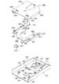
図4、図5は、従来のディスクドライブについて、主にそのディスク出し入れ構造を抽出して示す分解斜視図である。図4において、このディスクドライブは、それぞれ板金をプレス成形して成るメインフレーム110と、イジェクトプレート120と、ディスクホルダ130とを有している。
【0004】
メインフレーム110は、板状を呈する主板部111と、主板部111の両側端から直角上向きに延びる側板部112、113と、主板部111の後端から直角上向きに延びる背板部114と、主板部111の一部を切り起こして成る2つの支持片115及び2つの支持片116とを一体に有している。2つの支持片115及び2つの支持片116はそれぞれ、各切り起こしの一部を切り欠いて成る肩部115a及び116aを持っている。
【0005】
メインフレーム110の主板部111上には、ディスクを保持しつつ回転駆動するためのディスクテーブル140と、上下一対のヘッドをディスク表裏面にてその半径方向に駆動するためのキャリッジ150とが、メインフレーム110の前後方向に並べて設けられている。また、メインフレーム110の背板部114には、モータ160がその螺旋溝付きの回転軸をメインフレーム110の前後方向に平行に向けた状態で設けられている。
【0006】
ディスクテーブル140は、メインフレーム110の下側から図示しないディスク回転用のモータのロータアセンブリに直結され、回転駆動される。キャリッジ150は、モータ160の回転軸の螺旋溝に掛合した掛合部材と主板部111上に固定された案内シャフトの貫通した支持枠とを有している。キャリッジ150は、モータ160が回転すると前記掛合部材がモータ160の回転方向に応じて前後方向に連動することにより、メインフレーム110の前後方向、即ち、ディスクの半径方向に直線運動する。
【0007】
イジェクトプレート120は、略U字形の板状を呈する主板部121と、主板部121の両側端(U字の両辺外側)から直角上向きに延びる側板部122、123と、主板部121の前端(U字の底辺外側)から前方に延びるボタン取付部124と、メインフレーム110の2つの支持片115及び2つの支持片116に対応する位置に形成された2つの切欠125及び2つの孔126と、側板部122、123それぞれに各々2つずつ形成された案内溝部127と、側板部122の後方(U字左辺先端)にて外方に突出する曲げ部128とを有している。
【0008】
案内溝部127はそれぞれ、イジェクトプレート120の前方側の水平部分と後方側の傾斜部分とを持っている。また、主板部121のU字左辺先端には、メインフレーム110に設けられるダンパギヤ(図示せず)と噛合する直線ギヤ129が形成されている。
【0009】
イジェクトプレート120は、メインフレーム110に対して、その切欠125及び孔126にメインフレーム110の支持片115及び116を貫通させるようにして取付けられる。この取り付けによって、主板部121のうちの切欠または孔を規定する部分が、メインフレーム110の支持片115及び116の各肩部115a及び116aによって支持される。よって、イジェクトプレート120は、メインフレーム110に対して前後方向に摺動可能である一方、切欠または孔と支持片との形状関係によって規制されるので、上下方向や左右方向には殆んど動かない。また、側板部122に設けられた曲げ部128は、メインフレーム110の側板部112の内面に対して、僅かな間隙をおいて対向する。
【0010】
尚、主板部121が略U字形を呈しているので、イジェクトプレート120は、メインフレーム110に取り付けられているディスクテーブル140やキャリッジ150の動作を阻害することなく、それ自体の摺動動作が実現される。
【0011】
ディスクホルダ130は、キャリッジ150における上のヘッドを避け得る切欠を持つ主板部131と、主板部131の両側端から直角下向きに延び、さらにその先端が内方に延びることでディスクを把持可能な側板部132及び133と、側板部132及び133にてイジェクトプレート120の案内溝部127に対応する位置に外方へ突出する4つの軸134とを有している。
【0012】
そして、ディスクホルダ130は、メインフレーム110に取り付けられているイジェクトプレート120に対して、その軸134を案内溝部127に挿通させるようにして取付けられ、ディスクドライブが構成される。なお、ディスクドライブを構成するには、ディスクホルダ130をイジェクトプレート120に取り付けた組立体を、メインフレーム110に取り付ける方法がとられることもある。
【0013】
このディスクドライブでは、以上説明した基本構造に加えて、ディスクホルダ130の図示しない突起が、メインフレーム110の図示しない孔に挿通されるなどされる。このような構造により、ディスクホルダ130は、メインフレーム110に対して、上下方向に摺動可能である一方、前後方向や左右方向には殆んど動かぬよう規制される。よって、ディスクホルダ130は、イジェクトプレート120の案内溝部127の形状により、イジェクトプレート120の前後方向の摺動に応じて、上下方向に摺動可能である。また、イジェクトプレート120とディスクホルダ130との間には、引張バネ(図示せず)が張架される。これによって、イジェクトプレート120は、メインフレーム110の前方に牽引される。また、引張バネの牽引に反してメインフレーム110の後方に位置する箇所では、イジェクトプレート120は、ロック手段(図示せず)によってロックされる。さらに、ロック手段に連動してディスクを外部に排出する方向へ加重するイジェクト手段(図示せず)もある。また、ボタン取付部124には操作者がディスクのイジェクト操作をするためのボタン170が取り付けられる。
【0014】
次に、以上のような構造のディスクホルダによるディスク出し入れ動作を説明する。
【0015】
まず、ディスクのないときは、イジェクトプレート120はロック手段によりロックされて後方に位置し(引張バネは伸びた状態)、案内溝部127と軸134と関係によって、ディスクホルダ130は上方に位置する。
【0016】
次に、上方に位置するディスクホルダ130にディスクがあてがわれて押し込まれると、ロック手段のロックは外れ、イジェクトプレート120は伸びた状態の引張バネに牽引されて前方に移動し、ディスクホルダ130は降下して下方に位置する。このディスク挿入完了状態で、ディスクに対する記録あるいは再生処理がなされる。
【0017】
上記の状態で、ボタン170が押されると、イジェクトプレート120は後方に移動してロック手段により再びロックされて後方に位置し(引張バネは伸びた状態)、ディスクホルダ130は上方に位置する。また、ロック手段に連動して、イジェクト手段がディスクを外部に排出する方向へ加重し、ディスクは排出される。
【0018】
【発明が解決しようとする課題】
ところで、イジェクトプレート120は、切り起こしによる2つの支持片115及び2つの支持片116に、切り欠きにより形成された肩部115a及び116aにより摺動が案内される。肩部115a及び116aは、切断面で粗い端面であるので、摺動性に問題がある。これを考慮して、イジェクトプレート120と肩部115a及び116aとの接触部にグリースを塗布することが行われている。この場合、塗布されたグリースがイジェクトプレート120の内面側に至ってディスクに付着してしまうという問題点がある。
【0019】
そこで、本発明の課題は、メインフレームによるイジェクトプレートの摺動案内をスムーズにすることのできるディスクドライブを提供することにある。
【0020】
本発明の他の課題は、メインフレームに設けられるイジェクトプレートの摺動案内部に塗布されるグリースがディスクに付着することのないディスクドライブを提供することにある。
【0021】
【課題を解決するための手段】
本発明は、ディスクを保持しつつ回転駆動するためのディスクテーブルとヘッドをディスクの半径方向に駆動するためのキャリッジとが内面側の前後方向に配設されるメインフレームと、略U字形の板状を呈し、U字内に前記ディスクテーブルおよび前記キャリッジを回避させるようにして前記メインフレームの板面上に平行に、かつ外部からの加重力によって前記前後方向に摺動可能に前記内面側に取り付けられたイジェクトプレートと、前記イジェクトプレートの前後方向の摺動に応じて上下方向に摺動するディスクホルダとを有するディスクドライブにおいて、前記メインフレームの前記イジェクトプレートと対向する面には前記イジェクトプレートと当接してその摺動を案内するための突条を複数個所に設けると共に、これらの突条に近い位置にはそれぞれ前記イジェクトプレートの摺動を許容し得る程度の第1の開口を設け、前記イジェクトプレートの前記第1の開口に対応する個所にはそれぞれ切り下げ及び曲げによる第1のL形状部を下面側に形成し、該第1のL形状部の曲げ部を前記第1の開口を通して前記メインフレームの外側面に沿わせて前記イジェクトプレートの摺動を案内するようにしたことを特徴とする。
【0022】
なお、前記メインフレームの前記第1の開口のうち前記キャリッジに近い方の第1の開口に対応する箇所には、切り起こし及び曲げによる第2のL形状部を設け、前記イジェクトプレートの前記キャリッジに近い方の第1の開口に対応する個所には第2の開口を有し、前記第2のL形状部を前記第2の開口を通して前記イジェクトプレートの内面側に突出させて前記第2のL形状部の曲げ部で前記ディスクを支持する。
【0023】
また、前記突条は、前記キャリッジ寄りの両側の2箇所、前記ディスクの挿入口寄りの両側の2箇所にそれぞれ絞り加工により設けられることが好ましい。
【0024】
更に、前記キャリッジに近い方の2箇所に設けられた2つの前記第2のL形状部における前記曲げ部には更に、前記イジェクトプレートの内面側に沿うように押さえ部を設けることが好ましい。
【0025】
【発明の実施の形態】
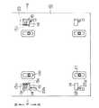
図1〜図3を参照して、本発明の好ましい実施の形態について説明する。図1は、メインフレーム10を外面側から見た図であり、図4に示すキャリッジ150とは反対側、すなわちディスクの挿入口側を示している。図1〜図3のいずれにおいても、イジェクトプレートの20の摺動案内に必要な構造部分のみを示しており、その他の構造については図4と同様の構造で良い。
【0026】
メインフレーム10は、主板部11の両側に側板部12、13を有する。主板部11のイジェクトプレート20と対向する面、すなわち内面側にはイジェクトプレート20と当接してその摺動を案内するための突条13を4個設けている。厳密に言えば、突条13は、図4に示すキャリッジに近い位置の両側に2箇所、ディスクの挿入口寄りの両側の2箇所にそれぞれ絞り加工により上端が平坦面になるように形成される。その形状は、イジェクトプレート20の摺動方向に長い略長四角形の枠状であり、枠内は開口13aになっている。メインフレーム10の主板部11にはまた、突条13に近い位置にそれぞれ、イジェクトプレート20の摺動を許容し得る程度の開口14(第1の開口)を設けている。
【0027】
一方、イジェクトプレート20においては、メインフレーム10の主板部11の4つの開口13aに対応する箇所にそれぞれ、絞り加工による筒状部21を下面側に延びるように形成し、開口13aに挿通させている。これにより、イジェクトプレート2の摺動時、筒状部21が開口13aの縁部で案内される。メインフレーム10の主板部11の4つの開口14に対応する箇所のイジェクトプレート20にはそれぞれ、切り下げ及び曲げによるL形状部(第1のL形状部)22を下面側に延びるように形成し、L形状部22の曲げ部22aを開口14を通してメインフレーム10の主板部11の外側面に沿わせてイジェクトプレート20の摺動を案内するようにしている。
【0028】
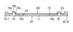
また、メインフレーム10の4つの開口14のうちキャリッジに近い方の2つの開口14に対応する箇所には、開口を形成する際に切り起こし及び曲げによるL形状部(第2のL形状部)15を設けている。一方、L形状部15に対応する箇所のイジェクトプレート20には開口(第2の開口)23が形成されている。そして、L形状部15を開口23を通してイジェクトプレート20の内面側に突出させてL形状部15の曲げ部15aでディスクを支持するようにしている。なお、この曲げ部15aの中央部には、ディスクの支持を点接触で行うようにするために、上方に凸の球面状突起15bが形成されている。
【0029】
更に、2つのL形状部15における曲げ部15aには更に、イジェクトプレート20の内面側に沿うように押さえ部15cが設けられている。
【0030】
本形態においては、イジェクトプレート20の摺動案内は、メインフレーム10の主板部11における突条13の平坦面とL形状部22における曲げ部22aの平坦面により行われるので、イジェクトプレート20の摺動はスムーズに行われる。また、イジェクトプレート20の摺動を円滑にするためのグリースは、L形状部22における曲げ部22aと主板部11の外側面との間に塗布される。したがってグリースがイジェクトプレート20の内面側に付着することは無い。
【0031】
【発明の効果】
以上説明してきたように、本発明によれば、メインフレームによるイジェクトプレートの摺動案内をスムーズにすることができ、しかも、メインフレームに設けられるイジェクトプレートの摺動案内部に塗布されるグリースがディスクに付着することの無いディスクドライブを提供することができる。
【図面の簡単な説明】
【図1】本発明の実施の形態によるディスクドライブについて、イジェクトプレートの摺動を案内する構造を抽出してメインフレームの外面側から示した図である。
【図2】図1に示すディスクドライブについて、切断線X〜Xによる断面を矢印A方向から見た図である。
【図3】図1に示すディスクドライブについて、切断線X〜Xによる断面を矢印B方向から見た図である。
【図4】従来例によるディスクドライブについて、主にそのディスク出し入れ構造を抽出して示す分解斜視図である。
【図5】図4に示すディスクドライブの曲げ部を含む部分的な断面図である。
【符号の説明】
10、110 メインフレーム
11、111 主板部
12−1、12−2、112、113 側板部
13a、14、23 開口
15、22 L形状部
15a、22a 曲げ部
15b 球面状突起
15c 押さえ部
20、120 イジェクトプレート
21 筒状部
114 背板部
115、116 支持片
115a、116a 肩部
124 ボタン取付部
130 ディスクホルダ
134 軸
140 ディスクテーブル
150 キャリッジ
160 モータ
170 ボタン[0001]
BACKGROUND OF THE INVENTION
The present invention relates to information processing by rotationally driving an information recording / reproducing disk (hereinafter simply referred to as a disk) having a structure in which a flexible disk portion on which information is recorded / reproduced is housed in a case, such as a magnetic disk. In particular, the present invention relates to an improvement in the structure for inserting and removing the disk.
[0002]
[Prior art]
In this type of disk drive, when performing information processing by rotating the disk, the disk is taken into the disk drive, held on a disk table for rotating while holding the disk, and recorded at a predetermined position on the disk.・ Apply a playback head. After the information processing is completed, the disc is taken out of the disc drive. Therefore, the disk drive has a disk insertion / removal structure.
[0003]
4 and 5 are exploded perspective views mainly showing the disk loading / unloading structure of a conventional disk drive. In FIG. 4, the disk drive has a
[0004]
The
[0005]
On the main plate portion 111 of the
[0006]
The disk table 140 is directly connected to the rotor assembly of a disk rotation motor (not shown) from the lower side of the
[0007]
The
[0008]
Each
[0009]
The
[0010]
Since the
[0011]
The
[0012]
Then, the
[0013]
In this disk drive, in addition to the basic structure described above, a protrusion (not shown) of the
[0014]
Next, a disk insertion / removal operation by the disk holder having the above structure will be described.
[0015]
First, when there is no disk, the
[0016]
Next, when the disk is applied to and pushed into the
[0017]
When the
[0018]
[Problems to be solved by the invention]
By the way, sliding of the
[0019]
SUMMARY OF THE INVENTION An object of the present invention is to provide a disk drive that can smoothly slide and guide an eject plate by a main frame.
[0020]
Another object of the present invention is to provide a disk drive in which grease applied to a sliding guide portion of an eject plate provided on a main frame does not adhere to the disk.
[0021]
[Means for Solving the Problems]
The present invention relates to a main frame in which a disk table for rotating and holding a disk and a carriage for driving a head in the radial direction of the disk are arranged in the front-rear direction on the inner surface side, and a substantially U-shaped plate In a U-shape, the disc table and the carriage are avoided in parallel to the plate surface of the main frame, and slidable in the front-rear direction by an external load force. In a disk drive having an attached eject plate and a disk holder that slides up and down in response to sliding in the front-rear direction of the eject plate, the surface of the main frame that faces the eject plate has the eject plate And a plurality of protrusions for abutting and guiding the sliding thereof, and these protrusions A first opening that allows the sliding of the eject plate is provided at a close position, and a first L-shaped portion formed by cutting and bending is provided at a position corresponding to the first opening of the eject plate. Is formed on the lower surface side, and the bent portion of the first L-shaped portion is guided along the outer surface of the main frame through the first opening to guide the sliding of the eject plate. To do.
[0022]
A second L-shaped portion formed by cutting and bending is provided at a position corresponding to the first opening closer to the carriage among the first openings of the main frame, and the carriage of the eject plate A second opening is provided at a position corresponding to the first opening closer to the second opening, and the second L-shaped portion protrudes through the second opening toward the inner surface side of the eject plate. The disk is supported by a bent portion of an L-shaped portion.
[0023]
The protrusions are preferably provided by drawing at two locations on both sides near the carriage and two locations on both sides near the disc insertion opening.
[0024]
Further, it is preferable that a pressing portion is further provided along the inner surface side of the eject plate at the two bent portions of the second L-shaped portions provided at two locations closer to the carriage.
[0025]
DETAILED DESCRIPTION OF THE INVENTION
A preferred embodiment of the present invention will be described with reference to FIGS. FIG. 1 is a view of the
[0026]
The
[0027]
On the other hand, in the
[0028]
In addition, an L-shaped portion (second L-shaped portion) formed by cutting and raising when forming the opening at a position corresponding to the two
[0029]
Further, a
[0030]
In this embodiment, the sliding guide of the
[0031]
【The invention's effect】
As described above, according to the present invention, the sliding guide of the eject plate by the main frame can be made smooth, and the grease applied to the sliding guide portion of the eject plate provided on the main frame can be obtained. A disk drive that does not adhere to the disk can be provided.
[Brief description of the drawings]
FIG. 1 is a diagram showing a structure for guiding sliding of an eject plate extracted from an outer surface side of a main frame in a disk drive according to an embodiment of the present invention.
2 is a view of the disk drive shown in FIG. 1 as viewed from the direction of arrow A, with a cross section taken along cutting lines X to X. FIG.
3 is a cross-sectional view of the disk drive shown in FIG.
FIG. 4 is an exploded perspective view mainly showing a disk loading / unloading structure of a conventional disk drive.
FIG. 5 is a partial cross-sectional view including a bent portion of the disk drive shown in FIG. 4;
[Explanation of symbols]
10, 110 Main frame 11, 111 Main plate portion 12-1, 12-2, 112, 113
Claims (4)
Translated fromJapanese前記メインフレームの前記イジェクトプレートと対向する面には前記イジェクトプレートと当接してその摺動を案内するための突条を複数個所に設けると共に、これらの突条に近い位置にはそれぞれ前記イジェクトプレートの摺動を許容し得る程度の第1の開口を設け、前記イジェクトプレートの前記第1の開口に対応する個所にはそれぞれ切り下げ及び曲げによる第1のL形状部を下面側に形成し、該第1のL形状部の曲げ部を前記第1の開口を通して前記メインフレームの外側面に沿わせて前記イジェクトプレートの摺動を案内するようにしたことを特徴とするディスクドライブ。A main frame in which a disk table for rotating the disk while holding the disk and a carriage for driving the head in the radial direction of the disk are disposed in the front-rear direction on the inner surface side, and a substantially U-shaped plate shape, Eject mounted in the U-shape so as to avoid the disk table and the carriage in parallel on the plate surface of the main frame and slidable in the front-rear direction by an external load force In a disk drive having a plate and a disk holder that slides in the vertical direction in response to sliding in the front-rear direction of the eject plate,
On the surface of the main frame facing the eject plate, there are provided a plurality of protrusions for contacting the eject plate and guiding its sliding, and the eject plate is located at a position close to these protrusions. A first opening that allows sliding of the first plate is formed, and a portion corresponding to the first opening of the eject plate is formed with a first L-shaped portion by lowering and bending on the lower surface side, A disc drive characterized in that a slide portion of the eject plate is guided along a bent portion of a first L-shaped portion along the outer surface of the main frame through the first opening.
Priority Applications (2)
| Application Number | Priority Date | Filing Date | Title |
|---|---|---|---|
| JP08102698AJP3690461B2 (en) | 1998-03-27 | 1998-03-27 | Disk drive |
| US09/274,702US6233114B1 (en) | 1998-03-27 | 1999-03-23 | Disk drive |
Applications Claiming Priority (1)
| Application Number | Priority Date | Filing Date | Title |
|---|---|---|---|
| JP08102698AJP3690461B2 (en) | 1998-03-27 | 1998-03-27 | Disk drive |
Publications (2)
| Publication Number | Publication Date |
|---|---|
| JPH11283307A JPH11283307A (en) | 1999-10-15 |
| JP3690461B2true JP3690461B2 (en) | 2005-08-31 |
Family
ID=13734975
Family Applications (1)
| Application Number | Title | Priority Date | Filing Date |
|---|---|---|---|
| JP08102698AExpired - Fee RelatedJP3690461B2 (en) | 1998-03-27 | 1998-03-27 | Disk drive |
Country Status (2)
| Country | Link |
|---|---|
| US (1) | US6233114B1 (en) |
| JP (1) | JP3690461B2 (en) |
Families Citing this family (5)
| Publication number | Priority date | Publication date | Assignee | Title |
|---|---|---|---|---|
| US6934119B2 (en) | 2000-06-27 | 2005-08-23 | Citizen Watch Co., Ltd. | Disk drive |
| JP5136230B2 (en)* | 2008-06-11 | 2013-02-06 | 株式会社Jvcケンウッド | Disc removing mechanism and disc reproducing apparatus using the disc removing mechanism |
| JP2010225217A (en)* | 2009-03-23 | 2010-10-07 | Funai Electric Co Ltd | Optical disk device |
| CN103869898A (en)* | 2012-12-11 | 2014-06-18 | 鸿富锦精密工业(深圳)有限公司 | Expansion card fixing device |
| CN105253012B (en)* | 2015-11-10 | 2017-10-17 | 广州电力机车有限公司 | The emulation mode of dumper between centers power distribution and differential control |
Family Cites Families (4)
| Publication number | Priority date | Publication date | Assignee | Title |
|---|---|---|---|---|
| US4760476A (en)* | 1984-05-15 | 1988-07-26 | Matsushita Electric Industrial Co., Ltd. | Drive mechanism for a magnetic disk reading head |
| US5025436A (en)* | 1988-12-20 | 1991-06-18 | Literal Corporation | Disk cartridge positioning mechanism for an information storage disk drive system |
| JPH0991943A (en) | 1995-09-26 | 1997-04-04 | Mitsumi Electric Co Ltd | Magnetic disk driver |
| JP3651502B2 (en) | 1995-09-27 | 2005-05-25 | ミツミ電機株式会社 | Disk driver |
- 1998
- 1998-03-27JPJP08102698Apatent/JP3690461B2/ennot_activeExpired - Fee Related
- 1999
- 1999-03-23USUS09/274,702patent/US6233114B1/ennot_activeExpired - Fee Related
Also Published As
| Publication number | Publication date |
|---|---|
| US6233114B1 (en) | 2001-05-15 |
| JPH11283307A (en) | 1999-10-15 |
Similar Documents
| Publication | Publication Date | Title |
|---|---|---|
| JP3690461B2 (en) | Disk drive | |
| US4224647A (en) | Magnetic tape-record/playback apparatus | |
| US5229987A (en) | Door arrangement for record medium insertion opening | |
| JP3651502B2 (en) | Disk driver | |
| JP3405374B2 (en) | Magnetic disk driver | |
| JPH04155626A (en) | Optical system cleaner for optical disc driver and optical driver | |
| JP3402336B2 (en) | Disk driver | |
| JPH08287575A (en) | Magnetic disk driver | |
| JP3915171B2 (en) | Disk drive | |
| JP3239395B2 (en) | Tape cassette | |
| JP2524167Y2 (en) | Incorrect cartridge insertion prevention mechanism | |
| JPH05982Y2 (en) | ||
| JP2616501B2 (en) | Cassette loading device | |
| JPS6245310Y2 (en) | ||
| JPH06103569B2 (en) | Disk device | |
| JP2574742Y2 (en) | Floppy disk drive | |
| JPH0648610Y2 (en) | Eject suppression mechanism | |
| JPH04102257A (en) | Recording medium loader | |
| JPH0991942A (en) | Disk driver | |
| JPH0329806Y2 (en) | ||
| JP2643727B2 (en) | Disk cartridge mounting device | |
| JP2534095Y2 (en) | Disk unit | |
| JP2000306358A (en) | Tape cassette | |
| JPH0450594Y2 (en) | ||
| JP2557165Y2 (en) | Floppy disk drive |
Legal Events
| Date | Code | Title | Description |
|---|---|---|---|
| A977 | Report on retrieval | Free format text:JAPANESE INTERMEDIATE CODE: A971007 Effective date:20050517 | |
| TRDD | Decision of grant or rejection written | ||
| A01 | Written decision to grant a patent or to grant a registration (utility model) | Free format text:JAPANESE INTERMEDIATE CODE: A01 Effective date:20050525 | |
| A61 | First payment of annual fees (during grant procedure) | Free format text:JAPANESE INTERMEDIATE CODE: A61 Effective date:20050607 | |
| R150 | Certificate of patent or registration of utility model | Free format text:JAPANESE INTERMEDIATE CODE: R150 | |
| FPAY | Renewal fee payment (event date is renewal date of database) | Free format text:PAYMENT UNTIL: 20110624 Year of fee payment:6 | |
| LAPS | Cancellation because of no payment of annual fees |