JP3686844B2 - Bone cement mixing apparatus and mixing method - Google Patents
Bone cement mixing apparatus and mixing methodDownload PDFInfo
- Publication number
- JP3686844B2 JP3686844B2JP2001146415AJP2001146415AJP3686844B2JP 3686844 B2JP3686844 B2JP 3686844B2JP 2001146415 AJP2001146415 AJP 2001146415AJP 2001146415 AJP2001146415 AJP 2001146415AJP 3686844 B2JP3686844 B2JP 3686844B2
- Authority
- JP
- Japan
- Prior art keywords
- mixing
- shaft
- mixing chamber
- handle
- bone cement
- Prior art date
- Legal status (The legal status is an assumption and is not a legal conclusion. Google has not performed a legal analysis and makes no representation as to the accuracy of the status listed.)
- Expired - Lifetime
Links
- 239000002639bone cementSubstances0.000titleclaimsdescription39
- 238000000034methodMethods0.000titledescription9
- 238000002347injectionMethods0.000claimsdescription9
- 239000007924injectionSubstances0.000claimsdescription9
- 230000033001locomotionEffects0.000claimsdescription8
- 230000008878couplingEffects0.000claims1
- 238000010168coupling processMethods0.000claims1
- 238000005859coupling reactionMethods0.000claims1
- 230000026058directional locomotionEffects0.000claims1
- 239000004568cementSubstances0.000description29
- 239000000203mixtureSubstances0.000description11
- 239000000463materialSubstances0.000description7
- 239000000843powderSubstances0.000description5
- 239000003517fumeSubstances0.000description4
- 210000000988bone and boneAnatomy0.000description3
- 239000007789gasSubstances0.000description3
- 230000000399orthopedic effectEffects0.000description3
- 239000000126substanceSubstances0.000description3
- VVQNEPGJFQJSBK-UHFFFAOYSA-NMethyl methacrylateChemical groupCOC(=O)C(C)=CVVQNEPGJFQJSBK-UHFFFAOYSA-N0.000description2
- 239000007788liquidSubstances0.000description2
- 238000004519manufacturing processMethods0.000description2
- 239000002184metalSubstances0.000description2
- 229910052751metalInorganic materials0.000description2
- 239000000178monomerSubstances0.000description2
- 230000002093peripheral effectEffects0.000description2
- 229920003023plasticPolymers0.000description2
- 239000004033plasticSubstances0.000description2
- 238000006557surface reactionMethods0.000description2
- 240000005979Hordeum vulgareSpecies0.000description1
- 235000007340Hordeum vulgareNutrition0.000description1
- 206010028813NauseaDiseases0.000description1
- 238000005452bendingMethods0.000description1
- 230000000295complement effectEffects0.000description1
- 238000011109contaminationMethods0.000description1
- 230000007423decreaseEffects0.000description1
- 230000007547defectEffects0.000description1
- 230000001627detrimental effectEffects0.000description1
- 208000002173dizzinessDiseases0.000description1
- 230000000694effectsEffects0.000description1
- 230000005802health problemEffects0.000description1
- 238000009434installationMethods0.000description1
- 210000003127kneeAnatomy0.000description1
- 239000007791liquid phaseSubstances0.000description1
- 150000002739metalsChemical class0.000description1
- 230000008693nauseaEffects0.000description1
- 238000012856packingMethods0.000description1
- 239000012071phaseSubstances0.000description1
- 229920003229poly(methyl methacrylate)Polymers0.000description1
- 238000006116polymerization reactionMethods0.000description1
- 239000004926polymethyl methacrylateSubstances0.000description1
- 230000002035prolonged effectEffects0.000description1
- 239000007787solidSubstances0.000description1
- 238000001356surgical procedureMethods0.000description1
- 238000009834vaporizationMethods0.000description1
- 230000008016vaporizationEffects0.000description1
- 239000002699waste materialSubstances0.000description1
Images


Classifications
- B—PERFORMING OPERATIONS; TRANSPORTING
- B01—PHYSICAL OR CHEMICAL PROCESSES OR APPARATUS IN GENERAL
- B01F—MIXING, e.g. DISSOLVING, EMULSIFYING OR DISPERSING
- B01F35/00—Accessories for mixers; Auxiliary operations or auxiliary devices; Parts or details of general application
- B01F35/30—Driving arrangements; Transmissions; Couplings; Brakes
- B01F35/32—Driving arrangements
- B01F35/323—Driving arrangements for vertical stirrer shafts
- A—HUMAN NECESSITIES
- A61—MEDICAL OR VETERINARY SCIENCE; HYGIENE
- A61B—DIAGNOSIS; SURGERY; IDENTIFICATION
- A61B17/00—Surgical instruments, devices or methods
- A61B17/56—Surgical instruments or methods for treatment of bones or joints; Devices specially adapted therefor
- A61B17/58—Surgical instruments or methods for treatment of bones or joints; Devices specially adapted therefor for osteosynthesis, e.g. bone plates, screws or setting implements
- A61B17/88—Osteosynthesis instruments; Methods or means for implanting or extracting internal or external fixation devices
- A61B17/8802—Equipment for handling bone cement or other fluid fillers
- A61B17/8805—Equipment for handling bone cement or other fluid fillers for introducing fluid filler into bone or extracting it
- A61B17/8825—Equipment for handling bone cement or other fluid fillers for introducing fluid filler into bone or extracting it characterised by syringe details
- B—PERFORMING OPERATIONS; TRANSPORTING
- B01—PHYSICAL OR CHEMICAL PROCESSES OR APPARATUS IN GENERAL
- B01F—MIXING, e.g. DISSOLVING, EMULSIFYING OR DISPERSING
- B01F33/00—Other mixers; Mixing plants; Combinations of mixers
- B01F33/50—Movable or transportable mixing devices or plants
- B01F33/501—Movable mixing devices, i.e. readily shifted or displaced from one place to another, e.g. portable during use
- B01F33/5011—Movable mixing devices, i.e. readily shifted or displaced from one place to another, e.g. portable during use portable during use, e.g. hand-held
- B—PERFORMING OPERATIONS; TRANSPORTING
- B01—PHYSICAL OR CHEMICAL PROCESSES OR APPARATUS IN GENERAL
- B01F—MIXING, e.g. DISSOLVING, EMULSIFYING OR DISPERSING
- B01F35/00—Accessories for mixers; Auxiliary operations or auxiliary devices; Parts or details of general application
- B01F35/30—Driving arrangements; Transmissions; Couplings; Brakes
- B01F35/33—Transmissions; Means for modifying the speed or direction of rotation
- B—PERFORMING OPERATIONS; TRANSPORTING
- B01—PHYSICAL OR CHEMICAL PROCESSES OR APPARATUS IN GENERAL
- B01F—MIXING, e.g. DISSOLVING, EMULSIFYING OR DISPERSING
- B01F35/00—Accessories for mixers; Auxiliary operations or auxiliary devices; Parts or details of general application
- B01F35/40—Mounting or supporting mixing devices or receptacles; Clamping or holding arrangements therefor
- B01F35/41—Mounting or supporting stirrer shafts or stirrer units on receptacles
- B01F35/412—Mounting or supporting stirrer shafts or stirrer units on receptacles by supporting both extremities of the shaft
- B01F35/4121—Mounting or supporting stirrer shafts or stirrer units on receptacles by supporting both extremities of the shaft at the top and at the bottom of the receptacle, e.g. for performing a conical orbital movement about a vertical axis
- A—HUMAN NECESSITIES
- A61—MEDICAL OR VETERINARY SCIENCE; HYGIENE
- A61B—DIAGNOSIS; SURGERY; IDENTIFICATION
- A61B17/00—Surgical instruments, devices or methods
- A61B17/56—Surgical instruments or methods for treatment of bones or joints; Devices specially adapted therefor
- A61B17/58—Surgical instruments or methods for treatment of bones or joints; Devices specially adapted therefor for osteosynthesis, e.g. bone plates, screws or setting implements
- A61B17/88—Osteosynthesis instruments; Methods or means for implanting or extracting internal or external fixation devices
- A61B17/8802—Equipment for handling bone cement or other fluid fillers
- A61B17/8805—Equipment for handling bone cement or other fluid fillers for introducing fluid filler into bone or extracting it
- A61B17/8822—Equipment for handling bone cement or other fluid fillers for introducing fluid filler into bone or extracting it characterised by means facilitating expulsion of fluid from the introducer, e.g. a screw pump plunger, hydraulic force transmissions, application of vibrations or a vacuum
- A—HUMAN NECESSITIES
- A61—MEDICAL OR VETERINARY SCIENCE; HYGIENE
- A61B—DIAGNOSIS; SURGERY; IDENTIFICATION
- A61B17/00—Surgical instruments, devices or methods
- A61B17/56—Surgical instruments or methods for treatment of bones or joints; Devices specially adapted therefor
- A61B17/58—Surgical instruments or methods for treatment of bones or joints; Devices specially adapted therefor for osteosynthesis, e.g. bone plates, screws or setting implements
- A61B17/88—Osteosynthesis instruments; Methods or means for implanting or extracting internal or external fixation devices
- A61B17/8802—Equipment for handling bone cement or other fluid fillers
- A61B17/8833—Osteosynthesis tools specially adapted for handling bone cement or fluid fillers; Means for supplying bone cement or fluid fillers to introducing tools, e.g. cartridge handling means
- A61B2017/8838—Osteosynthesis tools specially adapted for handling bone cement or fluid fillers; Means for supplying bone cement or fluid fillers to introducing tools, e.g. cartridge handling means for mixing bone cement or fluid fillers
- A—HUMAN NECESSITIES
- A61—MEDICAL OR VETERINARY SCIENCE; HYGIENE
- A61B—DIAGNOSIS; SURGERY; IDENTIFICATION
- A61B50/00—Containers, covers, furniture or holders specially adapted for surgical or diagnostic appliances or instruments, e.g. sterile covers
- A61B2050/005—Containers, covers, furniture or holders specially adapted for surgical or diagnostic appliances or instruments, e.g. sterile covers with a lid or cover
- A61B2050/0062—Containers, covers, furniture or holders specially adapted for surgical or diagnostic appliances or instruments, e.g. sterile covers with a lid or cover closable by a combination of rotation and translation
- A61B2050/0064—Containers, covers, furniture or holders specially adapted for surgical or diagnostic appliances or instruments, e.g. sterile covers with a lid or cover closable by a combination of rotation and translation by screwing
- A—HUMAN NECESSITIES
- A61—MEDICAL OR VETERINARY SCIENCE; HYGIENE
- A61B—DIAGNOSIS; SURGERY; IDENTIFICATION
- A61B50/00—Containers, covers, furniture or holders specially adapted for surgical or diagnostic appliances or instruments, e.g. sterile covers
- A61B2050/005—Containers, covers, furniture or holders specially adapted for surgical or diagnostic appliances or instruments, e.g. sterile covers with a lid or cover
- A61B2050/0066—Containers, covers, furniture or holders specially adapted for surgical or diagnostic appliances or instruments, e.g. sterile covers with a lid or cover with additional sealing means, e.g. O-ring
- A—HUMAN NECESSITIES
- A61—MEDICAL OR VETERINARY SCIENCE; HYGIENE
- A61F—FILTERS IMPLANTABLE INTO BLOOD VESSELS; PROSTHESES; DEVICES PROVIDING PATENCY TO, OR PREVENTING COLLAPSING OF, TUBULAR STRUCTURES OF THE BODY, e.g. STENTS; ORTHOPAEDIC, NURSING OR CONTRACEPTIVE DEVICES; FOMENTATION; TREATMENT OR PROTECTION OF EYES OR EARS; BANDAGES, DRESSINGS OR ABSORBENT PADS; FIRST-AID KITS
- A61F2/00—Filters implantable into blood vessels; Prostheses, i.e. artificial substitutes or replacements for parts of the body; Appliances for connecting them with the body; Devices providing patency to, or preventing collapsing of, tubular structures of the body, e.g. stents
- A61F2/02—Prostheses implantable into the body
- A61F2/30—Joints
- A61F2/46—Special tools for implanting artificial joints
- A61F2002/4685—Special tools for implanting artificial joints by means of vacuum
- B—PERFORMING OPERATIONS; TRANSPORTING
- B01—PHYSICAL OR CHEMICAL PROCESSES OR APPARATUS IN GENERAL
- B01F—MIXING, e.g. DISSOLVING, EMULSIFYING OR DISPERSING
- B01F2101/00—Mixing characterised by the nature of the mixed materials or by the application field
- B01F2101/20—Mixing of ingredients for bone cement
- B—PERFORMING OPERATIONS; TRANSPORTING
- B01—PHYSICAL OR CHEMICAL PROCESSES OR APPARATUS IN GENERAL
- B01F—MIXING, e.g. DISSOLVING, EMULSIFYING OR DISPERSING
- B01F27/00—Mixers with rotary stirring devices in fixed receptacles; Kneaders
- B01F27/05—Stirrers
- B01F27/11—Stirrers characterised by the configuration of the stirrers
- B01F27/112—Stirrers characterised by the configuration of the stirrers with arms, paddles, vanes or blades
- B01F27/1125—Stirrers characterised by the configuration of the stirrers with arms, paddles, vanes or blades with vanes or blades extending parallel or oblique to the stirrer axis
- B01F27/11251—Stirrers characterised by the configuration of the stirrers with arms, paddles, vanes or blades with vanes or blades extending parallel or oblique to the stirrer axis having holes in the surface
- B—PERFORMING OPERATIONS; TRANSPORTING
- B01—PHYSICAL OR CHEMICAL PROCESSES OR APPARATUS IN GENERAL
- B01F—MIXING, e.g. DISSOLVING, EMULSIFYING OR DISPERSING
- B01F33/00—Other mixers; Mixing plants; Combinations of mixers
- B01F33/70—Mixers specially adapted for working at sub- or super-atmospheric pressure, e.g. combined with de-foaming
Landscapes
- Health & Medical Sciences (AREA)
- Chemical Kinetics & Catalysis (AREA)
- Chemical & Material Sciences (AREA)
- Life Sciences & Earth Sciences (AREA)
- Orthopedic Medicine & Surgery (AREA)
- Surgery (AREA)
- Medical Informatics (AREA)
- General Health & Medical Sciences (AREA)
- Biomedical Technology (AREA)
- Heart & Thoracic Surgery (AREA)
- Nuclear Medicine, Radiotherapy & Molecular Imaging (AREA)
- Molecular Biology (AREA)
- Animal Behavior & Ethology (AREA)
- Engineering & Computer Science (AREA)
- Public Health (AREA)
- Veterinary Medicine (AREA)
- Mixers Of The Rotary Stirring Type (AREA)
- Prostheses (AREA)
- Surgical Instruments (AREA)
- Materials For Medical Uses (AREA)
- Dental Tools And Instruments Or Auxiliary Dental Instruments (AREA)
- Preparation Of Clay, And Manufacture Of Mixtures Containing Clay Or Cement (AREA)
Description
Translated fromJapanese【0001】
【発明の属する技術分野】
本発明は、整形外科用骨セメント等の混合及び射出に用いる装置に関する。
【0002】
【従来の技術】
整形外科用骨セメントは、人工股関節、人工膝関節、及び他の金属製補綴を適当な解剖学的部位に固着するために、世界中で使用されている。骨セメントは、通常はメチルメタクリレート・モノマー液とポリメチルメタクリレート粉末である2つの成分を合わせて完全に混合することによって生成される。この混合は通常単一の鉢及びへらを使用してなされる。医師はその後必要量のセメントを取って、セメントを予め形成された孔内に挿入したり、補綴の装着のために一部切除された骨の表面にセメントを塗布する前に手による取扱いを行う。セメントは手で塗布することもできるし、注射器に入れてこれを用いてつけることもできる。しかしながらこの単純な混合方法には2つの重大な欠陥があった。
【0003】
第1に、遊離したメチルメタクリレートのフューム(fume)が混合物から発散することである。これは不快な臭いを伴い且つ作業室内の人員に対して有害であるため、このフュームを除去するかまたはフュームの大気中への発散を防止することが望まれる。このフュームは吐き気とめまいとを引き起こすことが知られており、一般的に、特にその混合処理に携わる看護婦にとって不快なものである。最近、このフュームに長時間さらされることによってより深刻な健康障害をもたらす懸念も出てきている。職場の健康に関する現在の雇用関係法では医療関係スタッフは有害物質にさらされることに対しても保護されなければならないと規定されている。
【0004】
第2に、均質なセメント材を作成するためには混合効率が非常に高度である必要がある。空気は粉末内はもとより、混合容器の中及び周囲にも存在するため、混合過程においては、混合物中に空気が必然的に導入されてしまう。また、混合過程において生起するモノマーの気化流出によって空気泡が形成されてしまう。空気が導入されることによって生成されるセメントは弱くなり、また、セメントの接着部は通常大きな荷重を支持しなければならないことから、セメント材質の機械的強度を向上させるためにはできる限り混合物中の空気の量を少なくすることが重要である。
【0005】
混合物からできる限り空気を除去するためには、混合が真空下において行われることが好ましい。これによって混合物中の空気の量は著しく削減される。従来型の鉢とへらのシステムでの混合では、有孔値がほぼ20乃至25%の生成物を作成することができる。真空下における混合では、多くの場合、有孔値が5%未満のレベルにまで削減される。
【0006】
真空内にてセメントを混合するいくつかの装置が現在利用されている。この装置のなかに手持ち式混合鉢型のものがある。混合される物質は、真空状態となる鉢の中におかれる。物質の混合は、鉢の蓋を貫通して外側に延びているハンドルを手で回転して、鉢の中に延在する回転パドルを回転させることによって行われる。用途によってはこのような混合鉢を利用することが好ましい場合もあり、この型の混合鉢の一例はWO 93/10892の明細書に記載されている。外科医の多くはセメントの“手詰め(hand pack)”を好む。鉢を用いた混合は、その容器内での混合の便利さに慣れている看護婦によっても好まれる傾向がある。即ち、鉢は使用が容易であり、また、混合はタイミングが重要で、常に‘正初回(right first time)’の作業であることから、看護婦が自信をもって行うことが重要なのである。外科医の多くも鉢を用いた混合を好む傾向があるが、その理由は、混合物はそれを塗布する前に硬化を開始しないことが重要で、混合物の重合の進行を判断するための鉢からのセメントの試料の採取をいつでも容易に行うことができるからである。
【0007】
しかし用途によっては、混合したセメントを注射器を用いて骨に塗布することが好ましいか、或いは必要となる。実際に外科医、特にヨーロッパの外科医はセメントの“手詰め”に注射器型の装置を用いることを好む。骨セメントは、鉢の中で混合された場合、次にそれを射出用注射器に移す必要があるが、この作業は煩雑で時間のかかることがあり、混合物がより大量の閉じ込められた空気にさらされることもあり得る。この問題点は混合室と注射器とを組み合わせることによって解決された。一例として、EP−A−0178658の明細書には、供給装置に接続した混合容器を含む骨セメント混合用装置が開示されている。ここでは、真空下での試料の混合のために真空源が供給装置に接続される。この装置は非常に効率的な混合及び移送システムであることが立証されており、また、混合セメントを混合鉢から注射器へ移送する必要性をなくした。
【0008】
【発明が解決しようとする課題】
しかし、この装置は、成分が十分に混合されない領域、即ち‘死点’が、特に混合室の外辺部において生ずることから不適当であることがある。
【0009】
更に、EP−A−0178658の装置の混合パドルは、電気駆動回転モータによって回転される。このため、装置の製造コストがかさみ、占有する空間が大きくなり、専門家が必要となり、取り付けに時間がかかることになる。また、この装置は持ち運びが容易でなく、そのため、特に使用上の柔軟性に欠けていた。
【0010】
US4,758,096の明細書にも、射出用容器の中で骨セメントが混合される骨セメント混合装置が開示されている。この装置においては、“マッシャー”プレート型(masher plate-type)攪拌器を用いて、混合が手で行われる。マッシャープレートは、ハンドルに取着されたシャフトに取り付けられる。攪拌器は混合室内で軸線方向にも回転方向にも動かすことができ、使用者がハンドルを垂直方向及び回転方向に動かすことによって骨セメントを混合することが可能となる。しかし、このような混合の作業は厄介で効率が悪く、骨セメントの完全な混合ができずに、混合されない粉末の領域が残ってしまうことになる。
【0011】
本発明の目的は、上述のような問題点を解決することである。
【0012】
【課題を解決するための手段】
本発明の一実施例によれば、混合室と、前記混合室に回動可能に取着された混合部材と、前記混合部材を回動せしめる駆動手段とを有する骨セメント混合装置において、前記駆動手段が、前記混合室に対して軸線方向に往復運動可能なハンドルと、歯車機構とを含むことを特徴とし、前記歯車機構が、それによって前記ハンドルの軸線方向の動きが前記混合部材の回転運動に変換されるように前記ハンドルと前記混合部材との間に設けられることを特徴とする骨セメント混合装置が提供される。
【0013】
本発明の別の実施例によれば、混合室内に回転自在に取着された混合部材によって、混合される材料を入れた前記混合室内で骨セメントを混合する方法であって、前記混合室に対して軸線方向に駆動ハンドルを動かす過程を有し、前記ハンドルが歯車機構を介して前記混合部材と連結されており、前記ハンドルの軸線方向の動きが、前記歯車機構を介して前記混合部材の回転に変換されることを特徴とする骨セメントの混合方法が提供される。
【0014】
好適な歯車機構の型は“バーリーツイスト(barley twist)”機構であって、これはハンドルの下向きのストロークによって、ねじ山を切られたロッドが、混合部材に連結された駆動ブッシュをなすねじ山を切られた歯車ハウジングを動かして、混合部材に第1方向の回転力をもたらすものである。また、ハンドルの上向きのストロークにより、混合部材の逆方向の回転が引き起こされる。混合を行うときには、混合要素を交互に異なる方向に回転させることにより、完全な混合を行うことができる。“バーリーツイスト”機構を用いることによって、特に混合するセメントの粘性が高いときに厄介で使用者に疲労をもたらす、ハンドルを交互に順方向及び逆方向に回転させる作業が不要となり、このような単純なハンドルの押し引き作業を行えばよくなる。
【0015】
本発明はいかなる骨セメント混合室にも適用できるが、射出用注射器とともに用いるのが好ましい。即ち、注射器のシリンダは混合室の本体部を形成し、混合された骨セメントを射出させるためにプランジャがシリンダの一端に摺動自在に取着される。
【0016】
上述のように、その混合を真空下で行った場合、骨セメントの質は著しく改善される。従って、好適実施例においては、本発明は混合室内に真空状態を生成する手段を含む。
【0017】
完全な混合を行うために、混合部材はシャフトに取着されたパドル状のものとして形成されるのが好ましい。また好適実施例においては、シャフトには軸心を含む孔が設けられ、バーリーツイスト歯車機構のロッドがそれを貫通して延在し得る。1または2以上のパドルはシャフトから径方向外向きに延出しており、また、少なくとも1つのパドルはシャフトから混合室の壁に達するまで延び、それが回転すると混合室内部に残った全ての骨セメントがぬぐい取られることになる。
【0018】
混合した骨セメントを無駄にしないようにするために、混合パドルは、好ましくは、それが混合室から取り外される前にきれいにぬぐい取られるべきである。骨セメントの汚染を避け衛生的にこの処置を行うための方法は、混合室にスロットを設け、混合パドルがそれを通して混合室に差し込まれるようにすることである。つまり、このスロットの幅は混合パドルの厚みと実質的に等しく、混合を行った後に混合パドルを引き抜くときに、それに付着した残りの骨セメントをぬぐい取ることができるのである。
【0019】
スロットはシリンダのハンドルが取着される方の一端に一体的に設けられてもよく、この場合、混合の後にスロットを通して骨セメントが射出される。別の形態として、スロットを、シリンダと蓋との間に挟み込まれるキャップ、プレート等の別の部材に設けることも可能である。この場合、スロットを備えた部材は、混合パドルがスロットを通して引き抜かれた後、骨セメントの射出を行う前に取り外される。
【0020】
骨セメントの混合において、混合室の中にはセメント粉末とモノマー液とが交互に層をなすように入れられる。初めの状態ではセメントは非常に硬く、混合の開始には非常に大きな力が必要である。次に粉末相と液相の間で表面反応が起こり、ひとたび混合が開始されると混合に必要な力は急激に低下する。各層間の界面が大きくなるにつれ、表面反応は盛んになる。従って、各層間の界面を大きくし、取り扱いを一層楽にするために、シリンダの幅はできる限り大きくするべきである。
【0021】
一実施例においては、混合部材、ハンドル、及び歯車機構は、着脱自在な蓋アセンブリにおける一体的な構造単位として形成される。蓋は、シリンダの一端に例えば形状の一致するねじ山部分によって取着されるように形成される。混合が終了した後、混合部材、ハンドル、及び歯車機構を含む混合アセンブリを備えた蓋アセンブリは、例えばねじを緩めることによって取り外すことができ、好適実施例においては、その後ノズル等が代わりに取り付けられる。ノズルはプランジャと協働して、プランジャをシリンダに押し込んだときに混合された骨セメントがノズルを通して射出されるようにする。プランジャは手動式のもの、即ちハンドガン(hand gun)機構でもよいが、代わりにガス圧式ガン(gas powered pressure gun)を用いることもできる。
【0022】
しかし、多くの応用例、例えば股関節復位手術では、1または2以上の段階を踏んで行われるので、セメントを数バッチ分混合する必要がある。システムをより経済的なものとするために、好ましくは、混合パドルは使い捨てにし、ハンドル及び歯車機構は再利用可能なものとすべきである。従って、このような応用例では、駆動機構は、使用後に混合部材から取り外し可能にすべきである。
【0023】
本発明の第3実施例によれば、混合室と、前記混合室に回動可能に取着された混合部材と、前記混合部材を回転させるためのハンドルを備えた駆動手段とを有する骨セメント混合装置において、前記駆動手段が、前記混合室の蓋アセンブリによって支持されることを特徴とし、前記蓋アセンブリ及び前記駆動手段が、前記混合室及び前記混合部材から着脱可能であって、所望に応じて前記蓋アセンブリ及び前記駆動手段を別の混合室及び混合部材とともに再使用可能であることを特徴とする骨セメント混合装置が提供される。
【0024】
好ましくは気密シールが、蓋アセンブリと混合部材との間、蓋アセンブリと混合質との間、及び混合室とスタンドアセンブリとの間に設けられる。この実施例では、好適な歯車機構の駆動ブッシュは、好ましくはパドルから着脱可能であり、かつパドルシャフトの頂部に嵌合される形であれば便利である。また、嵌合部分にリブ−溝式位置決め機構が用いられるのが好ましい。
【0025】
混合室の内容物が十分に混合されたら、パドルは混合室の中に残して、蓋アセンブリ及び駆動手段を取り外すことができる。このことから、次の段階が、パドルを取り出し、骨セメントを塗布するためのノズルを装着する段階であることが看護婦にわかる。パドルをスロットを通して引き抜いたときにその表面がぬぐい取られるようになっていれば、一度蓋アセンブリを取り外した後にパドルをスロットに位置合わせするのは一層容易である。このような仕組みによって装置は非常に使いやすいものとなる。
【0026】
ノズルはプランジャと協働して、プランジャをシリンダに押し込んだときに混合された骨セメントがノズルを通して射出されるようにする。プランジャは手動で動かすもの、即ちハンドガン装置でもよいが、代わりにガス圧式ガンを用いることもできる。
【0027】
本発明の別の実施例によれば、混合室を画定する円筒形の注射器の本体部であるシリンダと、前記シリンダの一端に摺動自在に取着されたプランジャと、前記混合室に回動可能に取着された混合部材と、前記混合部材を回動せしめる駆動手段とを有する整形外科用骨セメント混合装置において、前記混合部材が、回動するシャフト上に前記シリンダの軸線に沿って設けられ、そこから径方向外向きに延出するブレードを備えており、前記シリンダ内部において、前記シャフトの回転が前記ブレードの前記シャフトの軸周りの回転をもたらすことを特徴とし、前記ブレードが前記シャフトから延出して前記シリンダの内側壁に達しており、前記ブレードの回転によって、前記シリンダの内部に存在する全ての前記骨セメントをぬぐい取るように設けられていることを特徴とする骨セメント混合装置が提供される。
【0028】
【発明の実施の形態】
以下、本発明の好適実施例について述べるが、これは本発明の例示のみを目的とするものであり、図面を参照しつつ説明する。
【0029】
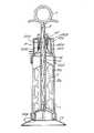
図1を参照すると、組み立てられた状態の骨セメント混合、射出用注射器が示されている。円筒形の注射器の本体部であるシリンダ1は混合室2を画定する。混合された骨セメントを射出するためのプランジャ3は、シリンダ1の一端に摺動自在な形で設けられている。混合部材は混合室2の内部に延びている。混合部材は、シリンダ1の軸線に沿ったシャフト4を含み、このシャフト4にはそこから径方向外向きに延出する数多くの固定されたパドルプレード5が備えられている。このブレード5は、粘性を有するセメントを混合する場合において生ずる曲げに対抗する充分な強度を有するプラスチックからなる。しかしながら、‘死点’の発生を防止し、完全な混合がなされることを確実にするために、軸線を挟み径方向に対称の位置にある2枚のプレード5は互いに補足的な形状を有するものである必要がある。シャフト4はハンドル7及び歯車機構6(詳細が図2に示されており、後に説明する)を含む駆動機構に取着される。ハンドル7はロッド8に固着されており、ロッド8はハンドル7によって軸線方向に動かすことができる。ロッド8は軸線方向に、シリンダ1の着脱自在な蓋9を貫通して延在し、更に混合パドルシャフト4に固着された駆動ブッシュ10を貫通して延在しており、その詳細は図2に示されている。好ましくは、ハンドル7は、ハンドル7が回転すると必然的にロッドに回転が生じ、更にパドルシャフト4の回転をもたらすようにロッド8に固着される。好適実施例のロッド8は、断面が矩形であるバーリーツイスト形状を有する。ロッド8は、それと寸法の等しい矩形の開口若しくは駆動ラグ11を通して駆動ブッシュ10を貫いている。駆動ハンドル7が押し込まれると、ロッド8は軸線方向にこの開口11を通して動き、混合室の中空シャフト4の中に入る。従って、ロッド8が開口11を通して軸線方向に動いたとき、開口の矩形の形状がロッド8の‘ねじれ’をなぞる形となっており、これによりブッシュ10及び混合パドルが、ハンドル7及びロッド8の軸線方向の動きに応じて回転することになる。同様に、ハンドル7が引っ張られると、ロッド8はブッシュ10の開口11を通して引き出され、混合部材は反対方向に回転することになる。従って、ハンドルの押し引きに応じて、混合ブレード5は混合室内においてシャフト4の軸周りに回転することになる。
【0030】
駆動ブッシュ10は回転自在に蓋9の内側に取着され、図1の実施例においては、混合部材のシャフト4は駆動ブッシュ10に固着されている。
【0031】
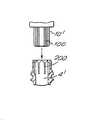
図3の実施例においては、上述のものと異なり混合部材は蓋アセンブリから着脱自在である。従って、駆動ブッシュ10′はその外周部に多数の位置決めリブ100を備えている(図5参照)。混合部材は中空シャフト4′を有する。混合部材のシャフト4′の頂部には、その内周部に前述のリブ100に対応する多数の溝200が設けられている。シャフト4′の開端部に向かって溝200は広げられており、これがリブ100を入れる広げられた入り口となる。これによって駆動ブッシュ10′をシャフト4′に嵌合することが容易になる。第1実施例のように、駆動ブッシュはロッド8と協働するように形成された開口を有し、ロッドの軸線方向の動きを混合部材の回転運動に変換する。図3に示すように、蓋にはシャフト4′の頂部を駆動ブッシュ10′に嵌合させる助けとなる、下向きにじょうご状に広がる案内部材201が取着されている。Oリングシール202はシャフト4′の頂部と案内部材201の頚部の内側表面との間で協働して、空気が駆動歯車機構を通って混合室の中に侵入するのを防ぐ。
【0032】
案内部材201の上端部203は、蓋9の下向きに延出する環状フランジ204の中に嵌め込まれ、蓋アセンブリ内部において駆動ブッシュ10′を回転自在に保持する。
【0033】
更に、Oリングシール205が蓋9とシリンダ1との間に設けられる。
【0034】
好適実施例においては、混合部材は、シャフト4の軸線を挟んで互いに反対向きに径方向外向きに延出する2枚の混合ブレード5を有する。各ブレード5は、シャフト4の軸線方向に沿って互い違いに設けられた突出部5Aとスペース部5Bとを含む。完全な混合が行われるのを確実にすべく、一方のブレード5の突出部5Aの位置は、他方のブレードのスペース部5Bの位置に対応している。また、突出部5Aそれ自体の形状は、中実でも、開口部が設けられていてもよい。開口部が設けられた突出部を用いると、充分な混合を行うことができるブレードを形成するために必要な材料の量が最小化される。もちろん、ブレード5の枚数は何枚でもよく、ブレードの設計はさまざまなものが可能である。例えば、それぞれの幅が異なる複数のブレードが用いられてもよい。
【0035】
混合室は、円筒形の注射器本体部1の一端を部分的に閉じることによってなる。混合室の一端はプランジャ3を軸線方向に受容するようになっている。また、この一端はスタンド13を受容し、また形状がスタンドのものと対応するねじ山によってスタンド13に固着されうる。シール206により、注射器本体部1とスタンド13との間のシールがなされる。混合室の別の一端には、好ましくは外向きのねじ山が設けられ、これが蓋9及びノズル12の対応する内向きのねじ山と螺合する。
【0036】
使用時においては、初めに混合されるセメント材料が混合室2に入れられ、混合室はその一端がプランジャ3またはプランジャの一部によって閉じられる。プランジャ3の内側表面は、好ましくは蓋の内側の形状と整合するようにドーム型の形状にされ、骨セメントが無駄に残らないようにされる。次にシリンダ1はスタンド13上に設置されるか、若しくは手で握られる。蓋9には内向きのねじ山が設けられており、これをシリンダ1の一端のねじ山と螺合させて、シャフト4及びブレード5がシリンダ1の中に延出する形に組み立てることができる。次に、ハンドル7を交互に押し引きすることによってブレード5をシャフト4の軸周りに回転させて、セメントを完全に混合する。この混合は真空状態の下で行われるが、真空ポンプは蓋9の吸引ポートに取着され得る。
【0037】
セメントが十分に混合されたとき、混合部材は、蓋をねじって外し、パドルシャフトから混合ロッド8を引き出すことによって取り除かれる。好適実施例においては、スロットを備えたカバー14が、シリンダ1と蓋9との間に設けられ、スロットの開口をシャフト4が貫通する形にされる。図3の実施例においては、パドルは、ロッド8が引き抜かれた後、当初はシリンダ1内に残される。駆動ブッシュ10′はシャフト4′の頂部から分離され、蓋アセンブリと共に取り除かれる。次に、パドルはスロットを通して別途引き出され得るが、このスロットの幅はブレード5の厚みと実質的に等しいので、ブレード5の表面上に付着したセメントはぬぐい取られることになる。第1実施例においては、パドルは常にハンドル及び蓋アセンブリと共に取り除かれる。
【0038】
次に、蓋9の代わりにアプリケータノズル12が取着される。次に、混合されたセメントが、適切な部位に加えられるプランジャ3の力によってノズル12から押し出される。ノズル12を通してセメントを押し出すのに用いられるプランジャには異なる型のものを用いてもよく、一例を挙げると手動式ガン16を用いることもできる。しかし、好適実施例においてはガス圧式ガンが用いられる。図4には、ノズル12が射出位置となるように装置に取り付けられたところが示されている。
【0039】
プランジャ3のセメントを押し込む側は、好ましくは混合室の射出端の形状に合わせてドーム状に形成され、射出されずに残るセメントの無駄を最小にする。
【0040】
プランジャ3は、好適なものについては上述したが、シリンダ1の一端から摺動自在に挿入されるものならば、いかなる型のものを用いてもよい。
【0041】
第1実施例の装置には、ハンドルのダウンストロークによって圧縮されて、逆方向のストロークを助けるように付勢するばね15が備えられている。このばねは第2実施例においては省略されている。
【0042】
シリンダ、混合機構、及びプランジャをかなり硬質のプラスティック材料から形成することによって、装置の製造コストを低減し、混合装置を使い捨てにできるようにすることが好ましい。もちろん、この装置を、例えば軽量金属のような他の材料から製造することも可能である。
【0043】
【発明の効果】
上記のように、本発明により、従来のものの欠点を解決し、より完全な骨セメントの混合が可能な骨セメント混合装置及び混合方法が提供される。
【図面の簡単な説明】
【図1】本発明に基づく混合装置の断面図である。
【図2】本発明の一実施例の混合装置における歯車機構のより詳細な断面図である。
【図3】本発明の別の実施例の混合装置の断面図である。
【図4】本発明の一実施例の混合装置の断面図であって、装置にノズルが装着され、セメント射出位置におかれているのが示されている。
【図5】図3の歯車機構と混合パドルとの間の係合部分を示す拡大組み立て断面図である。[0001]
BACKGROUND OF THE INVENTION
The present invention relates to an apparatus used for mixing and injecting orthopedic bone cement and the like.
[0002]
[Prior art]
Orthopedic bone cement is used throughout the world to secure hip prostheses, knee prostheses, and other metal prostheses to the appropriate anatomical site. Bone cement is produced by combining two components, usually methyl methacrylate monomer liquid and polymethyl methacrylate powder, thoroughly mixed. This mixing is usually done using a single bowl and spatula. The doctor then takes the required amount of cement and manually handles it before inserting the cement into a pre-formed hole or applying the cement to the partially excised bone surface for prosthetic attachment. . The cement can be applied by hand, or it can be applied using a syringe. However, this simple mixing method had two serious defects.
[0003]
First, the liberated methyl methacrylate fume emanates from the mixture. Since this has an unpleasant odor and is detrimental to personnel in the work room, it is desirable to remove this fume or prevent it from escaping into the atmosphere. This fume is known to cause nausea and dizziness and is generally unpleasant, especially for nurses involved in the mixing process. Recently, there have also been concerns that prolonged exposure to this fume can cause more serious health problems. Current employment laws relating to workplace health stipulate that medical staff must be protected from exposure to harmful substances.
[0004]
Secondly, the mixing efficiency needs to be very high in order to produce a homogeneous cement material. Since air exists not only in the powder but also in and around the mixing container, air is inevitably introduced into the mixture during the mixing process. In addition, air bubbles are formed by vaporization and outflow of the monomer generated in the mixing process. The cement produced by the introduction of air is weak and the cement bond usually has to support large loads, so in the mixture as much as possible to improve the mechanical strength of the cement material. It is important to reduce the amount of air.
[0005]
In order to remove as much air as possible from the mixture, it is preferred that the mixing be carried out under vacuum. This significantly reduces the amount of air in the mixture. Mixing with conventional bowl and spatula systems can produce a product with a porosity value of approximately 20-25%. Mixing under vacuum often reduces the porosity value to a level of less than 5%.
[0006]
Several devices are currently available that mix cement in a vacuum. Among these devices is a hand-held mixing bowl type. The substance to be mixed is placed in a bowl that is in a vacuum state. The mixing of the substances is done by rotating the handle that extends outwardly through the lid of the bowl and rotating the rotating paddle that extends into the bowl. Depending on the application, it may be preferred to use such a mixing bowl, an example of this type of mixing bowl being described in the specification of WO 93/10892. Many surgeons prefer cement “hand packs”. Mixing using a bowl also tends to be preferred by nurses accustomed to the convenience of mixing in the container. That is, the bowl is easy to use, and the timing of the mixing is important, and since it is always a 'right first time' operation, it is important for the nurse to do it with confidence. Many surgeons tend to prefer mixing in a bowl, because it is important that the mixture does not begin to cure before it is applied, and it can be removed from the bowl to determine the progress of the polymerization of the mixture. This is because a cement sample can be easily collected at any time.
[0007]
However, depending on the application, it may be preferable or necessary to apply the mixed cement to the bone using a syringe. Indeed, surgeons, especially European surgeons, prefer to use syringe-type devices for “hand-packing” cement. When bone cement is mixed in a pot, it must then be transferred to an injection syringe, which can be cumbersome and time consuming, exposing the mixture to a larger amount of trapped air. It can happen. This problem has been solved by combining a mixing chamber and a syringe. As an example, the specification of EP-A-0178658 discloses a device for mixing bone cement comprising a mixing container connected to a supply device. Here, a vacuum source is connected to the supply device for mixing the sample under vacuum. This device has proven to be a very efficient mixing and transfer system and has eliminated the need to transfer mixing cement from the mixing bowl to the syringe.
[0008]
[Problems to be solved by the invention]
However, this device may be unsuitable because areas where the components are not well mixed, i.e. 'dead point', occur especially in the outer periphery of the mixing chamber.
[0009]
Furthermore, the mixing paddle of the device of EP-A-0178658 is rotated by an electrically driven rotary motor. For this reason, the manufacturing cost of the apparatus is increased, the space occupied is increased, an expert is required, and the installation takes time. Further, this device is not easy to carry, and therefore lacks flexibility in use.
[0010]
The specification of US 4,758,096 also discloses a bone cement mixing device in which bone cement is mixed in an injection container. In this apparatus, mixing is done manually using a “masher plate-type” stirrer. The masher plate is attached to a shaft attached to the handle. The stirrer can be moved axially and rotationally within the mixing chamber, allowing the user to mix the bone cement by moving the handle vertically and rotationally. However, such a mixing operation is cumbersome and inefficient and does not allow complete mixing of the bone cement, leaving an unmixed powder area.
[0011]
The object of the present invention is to solve the above-mentioned problems.
[0012]
[Means for Solving the Problems]
According to one embodiment of the present invention, in the bone cement mixing apparatus, comprising: a mixing chamber; a mixing member rotatably attached to the mixing chamber; and a driving means for rotating the mixing member. The means includes a handle reciprocally movable in the axial direction with respect to the mixing chamber, and a gear mechanism, whereby the axial movement of the handle causes the rotational movement of the mixing member. A bone cement mixing device is provided between the handle and the mixing member to be converted into
[0013]
According to another embodiment of the present invention, there is provided a method of mixing bone cement in the mixing chamber containing a material to be mixed by a mixing member rotatably mounted in the mixing chamber, And moving the drive handle in the axial direction, the handle being connected to the mixing member via a gear mechanism, and the movement of the handle in the axial direction of the mixing member via the gear mechanism. A method of mixing bone cement is provided, characterized in that it is converted to rotation.
[0014]
A preferred type of gear mechanism is a “barley twist” mechanism, which is a screw with which the threaded rod forms a drive bush connected to the mixing member by a downward stroke of the handle. The chamfered gear housing is moved to provide the mixing member with a rotational force in the first direction. The upward stroke of the handle also causes the mixing member to rotate in the opposite direction. When mixing is performed, complete mixing can be performed by alternately rotating the mixing elements in different directions. Using the “Burly Twist” mechanism eliminates the need to rotate the handle alternately forward and backward, which is cumbersome and fatigues the user, especially when the cement being mixed is highly viscous. It will be sufficient to push and pull the handle.
[0015]
Although the present invention is applicable to any bone cement mixing chamber, it is preferably used with an injection syringe. That is, the cylinder of the syringe forms the main body of the mixing chamber, and the plunger is slidably attached to one end of the cylinder for injecting the mixed bone cement.
[0016]
As mentioned above, the quality of bone cement is significantly improved when the mixing is performed under vacuum. Thus, in a preferred embodiment, the present invention includes means for creating a vacuum in the mixing chamber.
[0017]
For complete mixing, the mixing member is preferably formed as a paddle attached to the shaft. Also, in a preferred embodiment, the shaft is provided with a hole that includes an axis, and the rod of the burly twist gear mechanism can extend therethrough. One or more paddles extend radially outward from the shaft, and at least one paddle extends from the shaft until it reaches the wall of the mixing chamber, and when it rotates, any bone remaining in the mixing chamber The cement will be wiped off.
[0018]
To avoid wasting the mixed bone cement, the mixing paddle should preferably be wiped clean before it is removed from the mixing chamber. A way to hygienically perform this procedure to avoid contamination of the bone cement is to provide a slot in the mixing chamber so that the mixing paddle can be inserted through it into the mixing chamber. That is, the width of the slot is substantially equal to the thickness of the mixing paddle, and when the mixing paddle is pulled out after mixing, the remaining bone cement attached to it can be wiped off.
[0019]
The slot may be integrally provided at one end to which the cylinder handle is attached, in which case bone cement is injected through the slot after mixing. Alternatively, the slot may be provided in another member such as a cap or a plate that is sandwiched between the cylinder and the lid. In this case, the member with the slot is removed after the mixing paddle has been pulled through the slot and before the injection of bone cement.
[0020]
In mixing bone cement, cement powder and monomer liquid are alternately layered in the mixing chamber. In the initial state, the cement is very hard and a very large force is required to start mixing. Next, a surface reaction occurs between the powder phase and the liquid phase, and once mixing is started, the force required for mixing rapidly decreases. As the interface between each layer grows, the surface reaction increases. Therefore, the width of the cylinder should be as large as possible in order to increase the interface between the layers and make handling easier.
[0021]
In one embodiment, the mixing member, handle, and gear mechanism are formed as an integral structural unit in a removable lid assembly. The lid is formed to be attached to one end of the cylinder by, for example, a thread portion having a matching shape. After mixing is complete, the lid assembly with the mixing assembly including the mixing member, handle, and gear mechanism can be removed, for example, by unscrewing, and in a preferred embodiment, a nozzle or the like is then installed instead. . The nozzle cooperates with the plunger so that the mixed bone cement is injected through the nozzle when the plunger is pushed into the cylinder. The plunger may be manually operated, that is, a hand gun mechanism, but a gas powered pressure gun may be used instead.
[0022]
However, in many applications, such as hip repositioning surgery, it is performed in one or more steps, so that several batches of cement need to be mixed. To make the system more economical, preferably the mixing paddle should be disposable and the handle and gear mechanism should be reusable. Thus, in such applications, the drive mechanism should be removable from the mixing member after use.
[0023]
According to a third embodiment of the present invention, a bone cement having a mixing chamber, a mixing member rotatably attached to the mixing chamber, and a driving means having a handle for rotating the mixing member. In the mixing apparatus, the driving means is supported by a lid assembly of the mixing chamber, and the lid assembly and the driving means are detachable from the mixing chamber and the mixing member, and can be used as desired. A bone cement mixing device is provided wherein the lid assembly and the drive means are reusable with another mixing chamber and mixing member.
[0024]
Preferably, hermetic seals are provided between the lid assembly and the mixing member, between the lid assembly and the mixture, and between the mixing chamber and the stand assembly. In this embodiment, it is convenient if the drive bushing of a suitable gear mechanism is preferably detachable from the paddle and fitted to the top of the paddle shaft. Moreover, it is preferable that a rib-groove type positioning mechanism is used for the fitting portion.
[0025]
Once the contents of the mixing chamber are thoroughly mixed, the paddle can be left in the mixing chamber and the lid assembly and drive means can be removed. From this, the nurse knows that the next step is to take out the paddle and attach a nozzle for applying bone cement. It is easier to align the paddle with the slot once the lid assembly is removed once the paddle is pulled through the slot so that its surface is wiped. This mechanism makes the device very easy to use.
[0026]
The nozzle cooperates with the plunger so that the mixed bone cement is injected through the nozzle when the plunger is pushed into the cylinder. The plunger may be manually moved, that is, a hand gun device, but a gas pressure gun may be used instead.
[0027]
According to another embodiment of the present invention, a cylinder that is a main body of a cylindrical syringe that defines a mixing chamber, a plunger that is slidably attached to one end of the cylinder, and pivots to the mixing chamber An orthopedic bone cement mixing device having a mixing member detachably attached and a driving means for rotating the mixing member, wherein the mixing member is provided on the rotating shaft along the axis of the cylinder. A blade extending radially outwardly therefrom, wherein rotation of the shaft within the cylinder causes rotation of the blade about an axis of the shaft, wherein the blade is the shaft. So that all the bone cement present in the cylinder is wiped off by the rotation of the blade. Bone cement mixing device is provided, characterized by being kicked.
[0028]
DETAILED DESCRIPTION OF THE INVENTION
In the following, preferred embodiments of the present invention will be described, which are only for the purpose of illustrating the present invention and will be described with reference to the drawings.
[0029]
Referring to FIG. 1, the assembled bone cement mixing and injection syringe is shown. A cylinder 1, which is the main body of a cylindrical syringe, defines a mixing chamber 2. A plunger 3 for injecting the mixed bone cement is provided at one end of the cylinder 1 so as to be slidable. The mixing member extends into the mixing chamber 2. The mixing member includes a shaft 4 along the axis of the cylinder 1, which is provided with a number of fixed
[0030]
The
[0031]
In the embodiment of FIG. 3, unlike the above, the mixing member is removable from the lid assembly. Accordingly, the drive bush 10 'is provided with a large number of
[0032]
An
[0033]
Further, an O-
[0034]
In a preferred embodiment, the mixing member has two
[0035]
The mixing chamber is formed by partially closing one end of the cylindrical syringe body 1. One end of the mixing chamber receives the plunger 3 in the axial direction. The one end also receives the
[0036]
In use, the cement material to be mixed first is placed in the mixing chamber 2, and one end of the mixing chamber is closed by the plunger 3 or a part of the plunger. The inner surface of the plunger 3 is preferably dome-shaped to match the inner shape of the lid so that bone cement is not wasted. The cylinder 1 is then placed on the
[0037]
When the cement is thoroughly mixed, the mixing member is removed by unscrewing the lid and pulling out the mixing rod 8 from the paddle shaft. In the preferred embodiment, a
[0038]
Next, the
[0039]
The side of the plunger 3 where the cement is pushed in is preferably formed in a dome shape to match the shape of the injection end of the mixing chamber, minimizing the waste of cement left uninjected.
[0040]
The plunger 3 has been described above for a suitable one, but any type of plunger may be used as long as it is slidably inserted from one end of the cylinder 1.
[0041]
The device of the first embodiment is provided with a
[0042]
Preferably, the cylinder, mixing mechanism, and plunger are formed from a fairly rigid plastic material to reduce the manufacturing cost of the device and allow the mixing device to be disposable. Of course, it is also possible to make the device from other materials, for example light metals.
[0043]
【The invention's effect】
As described above, according to the present invention, a bone cement mixing apparatus and a mixing method capable of solving the drawbacks of the conventional ones and allowing more complete bone cement mixing are provided.
[Brief description of the drawings]
FIG. 1 is a cross-sectional view of a mixing apparatus according to the present invention.
FIG. 2 is a more detailed cross-sectional view of a gear mechanism in a mixing apparatus according to an embodiment of the present invention.
FIG. 3 is a cross-sectional view of a mixing apparatus according to another embodiment of the present invention.
FIG. 4 is a cross-sectional view of a mixing device according to an embodiment of the present invention, showing that the device is fitted with a nozzle and placed in a cement injection position.
5 is an enlarged assembly cross-sectional view showing an engagement portion between the gear mechanism of FIG. 3 and a mixing paddle. FIG.
Claims (6)
Translated fromJapanese前記混合室内部に前記第1の末端に初期状態で隣接するように配置され、前記混合室の前記第2の末端に向かって前記中心軸に沿って摺動自在に設けられたプランジャと、
前記混合室に回動自在に取着された混合部材とを有する骨セメント混合装置において、
前記混合部材が、
前記中心軸に沿って延在し、リング状シールを備えた回動可能なシャフトと、
前記回動可能なシャフトに取り付けられ、そこから径方向に延在する少なくとも1枚のブレードであって、前記シャフトの回転により前記ブレードが前記混合室の内部で前記中心軸周りに回転する、該ブレードと、
前記混合部材を回動させる駆動手段とを有し、
前記駆動手段が、
前記混合室の前記第2の末端において前記注射器本体部の外部の位置に設けられたハンドルであって、前記中心軸と同一直線上に前記中心軸と同じ向きに延在する形で設けられた、該ハンドルと、
前記混合室の前記第2の末端において前記注射器本体部に着脱自在に結合された蓋アセンブリであって、前記蓋アセンブリは、前記駆動手段を支持しており、かつ前記蓋アセンブリは、前記混合室の前記第1の末端に対向する拡大された末端を有し、前記リング状シールに接触し、前記シャフトの一部を外囲するじょうご形状の部材を有する、該蓋アセンブリと、
前記ハンドルを前記混合部材に結合する歯車機構であって、前記歯車機構は、一方の端部が前記ハンドルに結合され、ねじ山を切られたロッドを有するバーリーツイスト機構であって、前記歯車機構は、前記混合部材の前記シャフトと結合されて前記シャフトとともに回転する回動自在な駆動ブッシュを有し、前記駆動ブッシュに前記ねじ山を切られたロッドが係合することによって、前記ハンドルの軸線方向の移動が前記駆動ブッシュの回転運動に変換され、前記混合部材に回転力を与える、該歯車機構とを有し、
前記リング形状のシールは、前記蓋アセンブリの前記じょうご形状の部材と前記シャフトとの間を気密シールを形成することを特徴とする骨セメント混合装置。A syringe body defining a cylindrical mixing chamber, the mixing chamber having a central axis and having first and second ends opposite to each other;
A plunger disposed in the mixing chamber so as to be adjacent to the first end in an initial state, and slidable along the central axis toward the second end of the mixing chamber;
The bone cement mixing device havinga rotatably mounted to the mixing element in the mixing chamber,
The mixing member is
A rotatable shaft extending along the central axis and provided with a ring-shaped seal;
At least one blade attached to the pivotable shaft and extending radially therefrom, wherein the blade rotates about the central axis within the mixing chamber by rotation of the shaft; A blade,
Drive means for rotating the mixing member,
The drive means
A handle provided at a position outside the syringe main body at the second end of the mixing chamber, provided in a form extending in the same direction as the central axis on the same straight line as the central axis. The handle;
A lid assembly removably coupled to the syringe body at the second end of the mixing chamber, the lid assembly supporting the drive means, and the lid assembly comprising the mixing chamber A lid assembly having a funnel-shaped member having an enlarged end opposite to the first end of the shaft, contacting the ring-shaped seal and enclosing a portion of the shaft;
A gear mechanism for coupling the handle to the mixing member, wherein the gear mechanism is a burley twist mechanism having one end coupled to the handle and a threaded rod. Has a rotatable drive bush coupled to the shaft of the mixing member and rotating with the shaft, and the threaded rod is engaged with the drive bush to thereby provide an axis of the handle. A gear mechanism that translates directional movement into rotational motion of the drive bushing and provides rotational force to the mixing member;
The bone cement mixing device,wherein the ring-shaped seal forms an airtight seal between the funnel-shaped member of the lid assembly and the shaft .
Applications Claiming Priority (2)
| Application Number | Priority Date | Filing Date | Title |
|---|---|---|---|
| GB9403362AGB9403362D0 (en) | 1994-02-22 | 1994-02-22 | Bone cement mixing apparatus |
| GB9403362.8 | 1994-02-22 |
Related Parent Applications (1)
| Application Number | Title | Priority Date | Filing Date |
|---|---|---|---|
| JP52168495ADivisionJP3238706B2 (en) | 1994-02-22 | 1995-02-22 | Bone cement mixing equipment |
Publications (2)
| Publication Number | Publication Date |
|---|---|
| JP2002052331A JP2002052331A (en) | 2002-02-19 |
| JP3686844B2true JP3686844B2 (en) | 2005-08-24 |
Family
ID=10750736
Family Applications (2)
| Application Number | Title | Priority Date | Filing Date |
|---|---|---|---|
| JP52168495AExpired - LifetimeJP3238706B2 (en) | 1994-02-22 | 1995-02-22 | Bone cement mixing equipment |
| JP2001146415AExpired - LifetimeJP3686844B2 (en) | 1994-02-22 | 2001-05-16 | Bone cement mixing apparatus and mixing method |
Family Applications Before (1)
| Application Number | Title | Priority Date | Filing Date |
|---|---|---|---|
| JP52168495AExpired - LifetimeJP3238706B2 (en) | 1994-02-22 | 1995-02-22 | Bone cement mixing equipment |
Country Status (9)
| Country | Link |
|---|---|
| US (2) | US5842785A (en) |
| EP (1) | EP0744991B1 (en) |
| JP (2) | JP3238706B2 (en) |
| AU (1) | AU679335B2 (en) |
| CA (1) | CA2183660C (en) |
| DE (1) | DE69505356T2 (en) |
| ES (1) | ES2123958T3 (en) |
| GB (2) | GB9403362D0 (en) |
| WO (1) | WO1995022402A1 (en) |
Families Citing this family (90)
| Publication number | Priority date | Publication date | Assignee | Title |
|---|---|---|---|---|
| US7143290B1 (en)* | 1995-02-13 | 2006-11-28 | Intertrust Technologies Corporation | Trusted and secure techniques, systems and methods for item delivery and execution |
| JP3371688B2 (en) | 1996-06-11 | 2003-01-27 | 三菱マテリアル株式会社 | Biological cement injector |
| IL128261A0 (en) | 1999-01-27 | 1999-11-30 | Disc O Tech Medical Tech Ltd | Expandable element |
| US5934803A (en)* | 1997-10-30 | 1999-08-10 | Physical Systems, Inc. | Apparatus and method for mixing multi-part reaction materials under vacuum |
| DE19748511B4 (en)* | 1997-11-03 | 2010-09-09 | Kabushiki Kaisha Morita Tokyo Seisakusho, Yono | Dental material vacuum mixer |
| EP1138396B1 (en)* | 1998-10-14 | 2005-12-28 | Kettenbach GmbH & CO. KG | Opener for opening a tubular bag comprising a pasty material |
| US6120174A (en)* | 1999-01-14 | 2000-09-19 | Bristol-Myers Squibb | Apparatus and method for mixing and dispensing bone cement |
| US6116773A (en)* | 1999-01-22 | 2000-09-12 | Murray; William M. | Bone cement mixer and method |
| US7621950B1 (en) | 1999-01-27 | 2009-11-24 | Kyphon Sarl | Expandable intervertebral spacer |
| GB2352408B (en) | 1999-07-27 | 2001-07-11 | Summit Medical Ltd | Orthopaedic bone cement mixing container |
| US20030069545A1 (en)* | 1999-12-06 | 2003-04-10 | Arm Douglas M. | Graft delivery syringe |
| DE20002075U1 (en)* | 2000-02-05 | 2000-10-19 | Meisel Nadine | Rotary device |
| US6395006B1 (en) | 2000-02-14 | 2002-05-28 | Telios Orthopedic Systems, Inc | Connector assembly for mating components, connector assembly for a bone cement mixing and delivery system, and bone cement container having a connector assembly |
| US6502608B1 (en) | 2000-02-14 | 2003-01-07 | Telios Orthopedic Systems, Inc. | Delivery apparatus, nozzle, and removable tip assembly |
| US6536937B1 (en) | 2000-02-14 | 2003-03-25 | Telios Orthopedic Systems, Inc. | Self-contained base for a surgical cement mixing system, binding material mixing base, and surgical bone cement mixing system |
| FR2811219B1 (en)* | 2000-07-05 | 2003-05-30 | Senaux Et Cie | SYRINGE FOR INJECTION OF CEMENT OF PROSTHESES |
| CA2426691A1 (en)* | 2000-10-25 | 2002-05-02 | Paul M. Sand | Systems and methods for mixing and transferring flowable materials |
| USD483495S1 (en) | 2000-10-25 | 2003-12-09 | Kyphon Inc. | Hand-held mixer for flowable materials |
| US6655828B2 (en)* | 2000-12-01 | 2003-12-02 | Depuy Orthopaedics, Inc. | Bone cement mixing apparatus having improved mixing blade configuration |
| US6702455B2 (en)* | 2000-12-01 | 2004-03-09 | Depuy Orthopaedics, Inc. | Bone cement mixing apparatus having improved gearing arrangement for driving a mixing blade |
| GB0218310D0 (en)* | 2002-08-07 | 2002-09-11 | Depuy Int Ltd | An instrument for preparing a bone cement material |
| USD490159S1 (en) | 2002-10-04 | 2004-05-18 | Kyphon Inc. | Hand-held mixer for flowable materials |
| ES2545328T3 (en) | 2003-03-14 | 2015-09-10 | Depuy Spine, Inc. | Bone cement hydraulic injection device in percutaneous vertebroplasty |
| US8066713B2 (en) | 2003-03-31 | 2011-11-29 | Depuy Spine, Inc. | Remotely-activated vertebroplasty injection device |
| US20050128867A1 (en)* | 2003-05-12 | 2005-06-16 | Henniges Bruce D. | Bone cement mixing and delivery system |
| US20040267272A1 (en)* | 2003-05-12 | 2004-12-30 | Henniges Bruce D | Bone cement mixing and delivery system |
| US8415407B2 (en) | 2004-03-21 | 2013-04-09 | Depuy Spine, Inc. | Methods, materials, and apparatus for treating bone and other tissue |
| US8062270B2 (en) | 2003-07-15 | 2011-11-22 | Spinal Generations, Llc | Method and device for delivering medicine to bone |
| CN100460049C (en)* | 2003-08-21 | 2009-02-11 | 药物混合系统股份公司 | Apparatus and methods for storing, mixing and dispensing components |
| US8579908B2 (en) | 2003-09-26 | 2013-11-12 | DePuy Synthes Products, LLC. | Device for delivering viscous material |
| US20050105384A1 (en)* | 2003-11-18 | 2005-05-19 | Scimed Life Systems, Inc. | Apparatus for mixing and dispensing a multi-component bone cement |
| US7524103B2 (en) | 2003-11-18 | 2009-04-28 | Boston Scientific Scimed, Inc. | Apparatus for mixing and dispensing a multi-component bone cement |
| GB2411849B (en)* | 2004-03-08 | 2007-08-29 | Summit Medical Ltd | Apparatus for mixing and discharging bone cement |
| US20050222538A1 (en)* | 2004-03-30 | 2005-10-06 | Sdgi Holdings, Inc. | Surgical system for delivery of viscous fluids |
| SE527528C2 (en)* | 2004-06-22 | 2006-04-04 | Bone Support Ab | Apparatus for the preparation of curable pulp and use of the apparatus |
| CN101065080B (en) | 2004-07-30 | 2021-10-29 | 德普伊新特斯产品有限责任公司 | Materials and Instruments for Manipulating Bone and Other Tissues |
| US8038682B2 (en) | 2004-08-17 | 2011-10-18 | Boston Scientific Scimed, Inc. | Apparatus and methods for delivering compounds into vertebrae for vertebroplasty |
| US20080319445A9 (en)* | 2004-08-17 | 2008-12-25 | Scimed Life Systems, Inc. | Apparatus and methods for delivering compounds into vertebrae for vertebroplasty |
| US8029183B2 (en)* | 2005-02-23 | 2011-10-04 | Biomet Manufacturing Corp. | Apparatus for mixing bone cement |
| US9381024B2 (en) | 2005-07-31 | 2016-07-05 | DePuy Synthes Products, Inc. | Marked tools |
| US9918767B2 (en) | 2005-08-01 | 2018-03-20 | DePuy Synthes Products, Inc. | Temperature control system |
| US8360629B2 (en)* | 2005-11-22 | 2013-01-29 | Depuy Spine, Inc. | Mixing apparatus having central and planetary mixing elements |
| US20080125722A1 (en)* | 2006-09-15 | 2008-05-29 | Howmedica International S. De R.L. | Syringe and stand |
| US20070185495A1 (en) | 2006-01-30 | 2007-08-09 | Howmedica International S. De R. L. | Plug-in syringe stand |
| EP1836992A1 (en) | 2006-03-10 | 2007-09-26 | 3M Innovative Properties Company | Mixing device and drive for the mixing device |
| US20070278229A1 (en)* | 2006-06-01 | 2007-12-06 | William Li | Container lid with push button operation |
| US20070291585A1 (en)* | 2006-06-14 | 2007-12-20 | Dave Sivers | Liquid container with stir mechanism |
| SE530232C2 (en)* | 2006-08-11 | 2008-04-08 | Biomet Cementing Technologies | Liquid container for bone cement mixers |
| AU2007297097A1 (en) | 2006-09-14 | 2008-03-20 | Depuy Spine, Inc. | Bone cement and methods of use thereof |
| US8950929B2 (en) | 2006-10-19 | 2015-02-10 | DePuy Synthes Products, LLC | Fluid delivery system |
| DE102008030623A1 (en)* | 2008-01-03 | 2009-07-09 | Umsonst-Kübler, Petra | Device for mixing a mass |
| US8088163B1 (en) | 2008-02-06 | 2012-01-03 | Kleiner Jeffrey B | Tools and methods for spinal fusion |
| US8317800B2 (en)* | 2008-04-22 | 2012-11-27 | Warsaw Orthopedic, Inc. | Injectable material delivery device with an integrated mixer |
| US20210378834A1 (en) | 2008-05-22 | 2021-12-09 | Spinal Surgical Strategies, Inc., A Nevada Corporation D/B/A Kleiner Device Labs | Spinal fusion cage system with inserter |
| US8308731B2 (en)* | 2008-09-02 | 2012-11-13 | Cook Medical Technologies Llc | Vertebroplasty all in one mixer |
| US20100114067A1 (en)* | 2008-10-31 | 2010-05-06 | Warsaw Orthopedic, Inc. | Multi-Chamber Mixing System |
| US8366748B2 (en) | 2008-12-05 | 2013-02-05 | Kleiner Jeffrey | Apparatus and method of spinal implant and fusion |
| US9247943B1 (en) | 2009-02-06 | 2016-02-02 | Kleiner Intellectual Property, Llc | Devices and methods for preparing an intervertebral workspace |
| US9060826B2 (en) | 2009-04-03 | 2015-06-23 | Ebi, Llc | Method and apparatus for delivering bone cement |
| US10973656B2 (en) | 2009-09-18 | 2021-04-13 | Spinal Surgical Strategies, Inc. | Bone graft delivery system and method for using same |
| US9629729B2 (en) | 2009-09-18 | 2017-04-25 | Spinal Surgical Strategies, Llc | Biological delivery system with adaptable fusion cage interface |
| US9186193B2 (en) | 2009-09-18 | 2015-11-17 | Spinal Surgical Strategies, Llc | Fusion cage with combined biological delivery system |
| US20170238984A1 (en) | 2009-09-18 | 2017-08-24 | Spinal Surgical Strategies, Llc | Bone graft delivery device with positioning handle |
| USD750249S1 (en) | 2014-10-20 | 2016-02-23 | Spinal Surgical Strategies, Llc | Expandable fusion cage |
| US8906028B2 (en) | 2009-09-18 | 2014-12-09 | Spinal Surgical Strategies, Llc | Bone graft delivery device and method of using the same |
| US10245159B1 (en) | 2009-09-18 | 2019-04-02 | Spinal Surgical Strategies, Llc | Bone graft delivery system and method for using same |
| CH702757A1 (en)* | 2010-02-22 | 2011-08-31 | Medmix Systems Ag | Syringe-like mixing device with distally option for self mixing element. |
| AU2011305680B2 (en)* | 2010-09-20 | 2014-09-11 | Jeffrey Kleiner | Fusion cage with combined biological delivery system |
| JP5766872B2 (en)* | 2011-05-06 | 2015-08-19 | ネステク ソシエテ アノニム | Mixer sensor and method for using the mixer sensor |
| DE102011119371B3 (en) | 2011-11-25 | 2013-04-04 | Heraeus Medical Gmbh | Device for mixing bone cement |
| DE102011119377B3 (en)* | 2011-11-25 | 2013-04-04 | Heraeus Medical Gmbh | Storage and mixing device for bone cement |
| US9630355B2 (en)* | 2011-11-30 | 2017-04-25 | King Abdulaziz City For Science And Technology | Batch mixer with plunger |
| US9358715B2 (en) | 2012-04-13 | 2016-06-07 | Kyphon SÀRL | Mixer gun system and method |
| US9211670B1 (en)* | 2013-03-11 | 2015-12-15 | Galomb, Inc. | Support apparatus for injection tube assembly |
| GB2514535A (en) | 2013-03-18 | 2014-12-03 | Summit Medical Ltd | An apparatus for mixing and delivering bone cement |
| US10653470B2 (en)* | 2014-02-19 | 2020-05-19 | Spinal Generation, LLC | Compressible mixing and delivery system for medical substances |
| US9550028B2 (en)* | 2014-05-06 | 2017-01-24 | Biomet Biologics, LLC. | Single step desiccating bead-in-syringe concentrating device |
| WO2016032454A1 (en)* | 2014-08-27 | 2016-03-03 | Halliburton Energy Services, Inc. | Actuatable paddle and methods of use |
| USD797290S1 (en) | 2015-10-19 | 2017-09-12 | Spinal Surgical Strategies, Llc | Bone graft delivery tool |
| WO2017147404A1 (en)* | 2016-02-25 | 2017-08-31 | Academia Sinica | Syringe apparatus for stirring and delivering composition containing cells |
| JP6488246B2 (en)* | 2016-02-29 | 2019-03-20 | 株式会社ニフコ | Stirrer |
| JP6854614B2 (en)* | 2016-09-30 | 2021-04-07 | サンコーテクノ株式会社 | Stirrer, stirring unit and stirring method |
| US10575887B2 (en)* | 2017-08-04 | 2020-03-03 | Medtronic Holding Company Sàrl | Dispensing system and methods of use |
| WO2019023805A1 (en) | 2017-08-04 | 2019-02-07 | Mark Robert Towler | A storage, mixing and dispensing device |
| US10758287B2 (en)* | 2018-09-13 | 2020-09-01 | Warsaw Orthopedic, Inc. | Bone material mixing and dispensing devices and methods |
| US11229468B2 (en) | 2019-06-11 | 2022-01-25 | Vivex Biologics Group, Inc. | Mixing syringe and method of use |
| US12029862B2 (en)* | 2019-12-20 | 2024-07-09 | Biosense Webster (Israel) Ltd. | Expandable assembly catheter |
| CN112871065A (en)* | 2021-01-20 | 2021-06-01 | 河北兑源新型建材有限公司 | Preparation equipment and use method of waterproof coating |
| CN115726047B (en)* | 2022-11-03 | 2023-07-28 | 温州佳远生物科技有限公司 | Preparation method of pure chitosan fiber |
| KR20250104161A (en)* | 2023-12-29 | 2025-07-08 | (주)시지바이오 | Bone graft material mixer |
Family Cites Families (30)
| Publication number | Priority date | Publication date | Assignee | Title |
|---|---|---|---|---|
| US400547A (en)* | 1889-04-02 | Charles baker crafton | ||
| US904935A (en)* | 1908-04-07 | 1908-11-24 | Thomas N Brown | Churn. |
| US1003910A (en)* | 1910-07-23 | 1911-09-19 | Nathaniel J Johnson | Churn. |
| US1068450A (en)* | 1912-06-22 | 1913-07-29 | Dorsey Mfg Company | Beater and mixer. |
| US1100683A (en)* | 1913-07-26 | 1914-06-16 | Henry S Warner | Egg-beater. |
| US1165307A (en)* | 1913-09-11 | 1915-12-21 | Edward D Farmer | Culinary beater. |
| US1159080A (en)* | 1914-12-31 | 1915-11-02 | Sanitary Bottle Washing Company Ltd | Kitchen utensil. |
| US1196612A (en)* | 1915-09-25 | 1916-08-29 | Robert Lee Taylor | Oscillating churn-dasher. |
| US1238461A (en)* | 1915-11-20 | 1917-08-28 | Paul Tripke | Combined egg-separator and juice-extractor, and beating device. |
| US1237585A (en)* | 1915-11-20 | 1917-08-21 | Paul Tripke | Combined egg-separator and beating device. |
| US1282148A (en)* | 1915-12-20 | 1918-10-22 | Paul Tripke | Combined egg separator and beater. |
| US1948431A (en)* | 1932-07-26 | 1934-02-20 | Rolph William Mair | Mixing device |
| US2162348A (en)* | 1938-10-21 | 1939-06-13 | Na Mac Products Company | Liquid dispenser and mixer |
| DE883326C (en)* | 1951-11-25 | 1953-07-16 | Hans Koehler | Pharmaceutical manufacturing facility |
| US2749098A (en)* | 1955-07-21 | 1956-06-05 | Albert H Johnson | Mixer |
| US3009686A (en)* | 1960-04-29 | 1961-11-21 | Kaplan Nathan | Mixing device |
| GB912237A (en)* | 1960-08-19 | 1962-12-05 | Evomastics Ltd | Improvements in and relating to mixing devices |
| US3115664A (en) | 1961-03-23 | 1963-12-31 | Re Giovanni | Mixing-stirring cap for nail polish bottles and the like |
| US3606094A (en)* | 1969-06-05 | 1971-09-20 | Peter B Mills | Mixing and dispensing syringe |
| GB1430064A (en)* | 1972-04-07 | 1976-03-31 | Gemco Ware Inc | Food mixer |
| SE450545B (en)* | 1984-10-19 | 1987-07-06 | Mit Ab | PROCEDURE AND DEVICE FOR MANUFACTURING BENCEMENT FOR FIXING PROSTHESIS |
| SE447785B (en)* | 1985-12-23 | 1986-12-15 | Mit Ab | DEVICE FOR APPLIANCES TO ALLOW BENCEMENT MIXING UNDER VACUUM |
| US4961647A (en)* | 1986-04-04 | 1990-10-09 | Dhd Medical Products | Orthopedic cement mixer |
| US4973168A (en)* | 1989-01-13 | 1990-11-27 | Chan Kwan Ho | Vacuum mixing/bone cement cartridge and kit |
| SE462315B (en)* | 1989-05-03 | 1990-06-11 | Surgitec Ab | DEVICE FOR MANUFACTURING BENCEMENT |
| US5265956A (en)* | 1991-09-30 | 1993-11-30 | Stryker Corporation | Bone cement mixing and loading apparatus |
| GB9126011D0 (en) | 1991-12-06 | 1992-02-05 | Summit Medical Ltd | Bone cement mixing device |
| SE510490C2 (en)* | 1992-02-07 | 1999-05-31 | Scandimed International Ab | Process for producing bone cement and apparatus for carrying out the process |
| US5368386A (en)* | 1993-11-16 | 1994-11-29 | Murray; William M. | Manual bone cement mixing device |
| US5857772A (en)* | 1997-12-11 | 1999-01-12 | Washington; Booker T. | Lid with a rotatable paddle for stirring paint |
- 1994
- 1994-02-22GBGB9403362Apatent/GB9403362D0/enactivePending
- 1995
- 1995-02-22GBGB9617290Apatent/GB2301045B/ennot_activeExpired - Lifetime
- 1995-02-22JPJP52168495Apatent/JP3238706B2/ennot_activeExpired - Lifetime
- 1995-02-22USUS08/696,917patent/US5842785A/ennot_activeExpired - Lifetime
- 1995-02-22DEDE69505356Tpatent/DE69505356T2/ennot_activeExpired - Lifetime
- 1995-02-22AUAU17131/95Apatent/AU679335B2/ennot_activeExpired
- 1995-02-22EPEP95909026Apatent/EP0744991B1/ennot_activeExpired - Lifetime
- 1995-02-22ESES95909026Tpatent/ES2123958T3/ennot_activeExpired - Lifetime
- 1995-02-22CACA002183660Apatent/CA2183660C/ennot_activeExpired - Lifetime
- 1995-02-22WOPCT/GB1995/000365patent/WO1995022402A1/enactiveIP Right Grant
- 1998
- 1998-06-10USUS09/095,205patent/US6592247B1/ennot_activeExpired - Lifetime
- 2001
- 2001-05-16JPJP2001146415Apatent/JP3686844B2/ennot_activeExpired - Lifetime
Also Published As
| Publication number | Publication date |
|---|---|
| US6592247B1 (en) | 2003-07-15 |
| WO1995022402A1 (en) | 1995-08-24 |
| JP3238706B2 (en) | 2001-12-17 |
| DE69505356D1 (en) | 1998-11-19 |
| EP0744991B1 (en) | 1998-10-14 |
| US5842785A (en) | 1998-12-01 |
| DE69505356T2 (en) | 1999-05-06 |
| GB2301045A (en) | 1996-11-27 |
| ES2123958T3 (en) | 1999-01-16 |
| GB9617290D0 (en) | 1996-09-25 |
| GB9403362D0 (en) | 1994-04-13 |
| AU1713195A (en) | 1995-09-04 |
| CA2183660A1 (en) | 1995-08-24 |
| JPH09511438A (en) | 1997-11-18 |
| EP0744991A1 (en) | 1996-12-04 |
| CA2183660C (en) | 2004-03-30 |
| GB2301045B (en) | 1997-12-03 |
| JP2002052331A (en) | 2002-02-19 |
| AU679335B2 (en) | 1997-06-26 |
Similar Documents
| Publication | Publication Date | Title |
|---|---|---|
| JP3686844B2 (en) | Bone cement mixing apparatus and mixing method | |
| CA2125165C (en) | Bone cement mixing device | |
| EP2243545B1 (en) | Bone cement mixing and delivery device for injection | |
| AU740212B2 (en) | Apparatus for storing, mixing, and dispensing two-component bone cement | |
| JP6727248B2 (en) | Equipment for mixing and transporting bone cement | |
| EP0725673A1 (en) | Automated bone cement mixing apparatus | |
| US6874927B2 (en) | Orthopaedic cement mixing and dispensing device | |
| AU2001230218A1 (en) | Orthopaedic cement mixing device | |
| US20060250888A1 (en) | Orthopaedic cement mixing device | |
| US6832682B1 (en) | Orthopaedic bone cement mixing container | |
| HK40040134A (en) | An apparatus for mixing and delivering bone cement | |
| GB2430165A (en) | Othopaedic cement mixing device |
Legal Events
| Date | Code | Title | Description |
|---|---|---|---|
| A131 | Notification of reasons for refusal | Free format text:JAPANESE INTERMEDIATE CODE: A131 Effective date:20041130 | |
| A601 | Written request for extension of time | Free format text:JAPANESE INTERMEDIATE CODE: A601 Effective date:20050228 | |
| A602 | Written permission of extension of time | Free format text:JAPANESE INTERMEDIATE CODE: A602 Effective date:20050314 | |
| A521 | Written amendment | Free format text:JAPANESE INTERMEDIATE CODE: A523 Effective date:20050405 | |
| TRDD | Decision of grant or rejection written | ||
| A01 | Written decision to grant a patent or to grant a registration (utility model) | Free format text:JAPANESE INTERMEDIATE CODE: A01 Effective date:20050510 | |
| A61 | First payment of annual fees (during grant procedure) | Free format text:JAPANESE INTERMEDIATE CODE: A61 Effective date:20050606 | |
| R150 | Certificate of patent or registration of utility model | Free format text:JAPANESE INTERMEDIATE CODE: R150 | |
| FPAY | Renewal fee payment (event date is renewal date of database) | Free format text:PAYMENT UNTIL: 20080610 Year of fee payment:3 | |
| FPAY | Renewal fee payment (event date is renewal date of database) | Free format text:PAYMENT UNTIL: 20090610 Year of fee payment:4 | |
| FPAY | Renewal fee payment (event date is renewal date of database) | Free format text:PAYMENT UNTIL: 20090610 Year of fee payment:4 | |
| FPAY | Renewal fee payment (event date is renewal date of database) | Free format text:PAYMENT UNTIL: 20100610 Year of fee payment:5 | |
| FPAY | Renewal fee payment (event date is renewal date of database) | Free format text:PAYMENT UNTIL: 20100610 Year of fee payment:5 | |
| FPAY | Renewal fee payment (event date is renewal date of database) | Free format text:PAYMENT UNTIL: 20110610 Year of fee payment:6 | |
| FPAY | Renewal fee payment (event date is renewal date of database) | Free format text:PAYMENT UNTIL: 20120610 Year of fee payment:7 | |
| FPAY | Renewal fee payment (event date is renewal date of database) | Free format text:PAYMENT UNTIL: 20120610 Year of fee payment:7 | |
| FPAY | Renewal fee payment (event date is renewal date of database) | Free format text:PAYMENT UNTIL: 20130610 Year of fee payment:8 | |
| R250 | Receipt of annual fees | Free format text:JAPANESE INTERMEDIATE CODE: R250 | |
| R250 | Receipt of annual fees | Free format text:JAPANESE INTERMEDIATE CODE: R250 | |
| EXPY | Cancellation because of completion of term |