JP3686117B2 - Ultrasonic incision coagulator - Google Patents
Ultrasonic incision coagulatorDownload PDFInfo
- Publication number
- JP3686117B2 JP3686117B2JP08146895AJP8146895AJP3686117B2JP 3686117 B2JP3686117 B2JP 3686117B2JP 08146895 AJP08146895 AJP 08146895AJP 8146895 AJP8146895 AJP 8146895AJP 3686117 B2JP3686117 B2JP 3686117B2
- Authority
- JP
- Japan
- Prior art keywords
- ultrasonic
- incision
- coagulation
- ultrasonic probe
- living tissue
- Prior art date
- Legal status (The legal status is an assumption and is not a legal conclusion. Google has not performed a legal analysis and makes no representation as to the accuracy of the status listed.)
- Expired - Fee Related
Links
- 238000005345coagulationMethods0.000claimsdescription149
- 230000015271coagulationEffects0.000claimsdescription148
- 239000000523sampleSubstances0.000claimsdescription130
- 230000001112coagulating effectEffects0.000claimsdescription10
- 238000003780insertionMethods0.000description45
- 230000037431insertionEffects0.000description45
- 238000011282treatmentMethods0.000description45
- XLYOFNOQVPJJNP-UHFFFAOYSA-NwaterSubstancesOXLYOFNOQVPJJNP-UHFFFAOYSA-N0.000description14
- 230000000740bleeding effectEffects0.000description9
- 238000010586diagramMethods0.000description9
- 230000000694effectsEffects0.000description9
- 238000000034methodMethods0.000description5
- 239000008280bloodSubstances0.000description4
- 210000004369bloodAnatomy0.000description4
- 230000007246mechanismEffects0.000description4
- 230000002093peripheral effectEffects0.000description4
- RTAQQCXQSZGOHL-UHFFFAOYSA-NTitaniumChemical compound[Ti]RTAQQCXQSZGOHL-UHFFFAOYSA-N0.000description3
- 238000002224dissectionMethods0.000description3
- 210000003811fingerAnatomy0.000description3
- 239000000463materialSubstances0.000description3
- 229910052719titaniumInorganic materials0.000description3
- 239000010936titaniumSubstances0.000description3
- 230000008859changeEffects0.000description2
- 230000008569processEffects0.000description2
- 230000001681protective effectEffects0.000description2
- 230000001225therapeutic effectEffects0.000description2
- 239000000560biocompatible materialSubstances0.000description1
- 238000004140cleaningMethods0.000description1
- 230000003247decreasing effectEffects0.000description1
- 230000009467reductionEffects0.000description1
- 230000004044responseEffects0.000description1
- 238000001356surgical procedureMethods0.000description1
- 210000003813thumbAnatomy0.000description1
- 238000009211ultrasonic lithotripsyMethods0.000description1
- 210000001835visceraAnatomy0.000description1
Images


Classifications
- A—HUMAN NECESSITIES
- A61—MEDICAL OR VETERINARY SCIENCE; HYGIENE
- A61B—DIAGNOSIS; SURGERY; IDENTIFICATION
- A61B17/00—Surgical instruments, devices or methods
- A61B17/32—Surgical cutting instruments
- A61B17/320068—Surgical cutting instruments using mechanical vibrations, e.g. ultrasonic
- A—HUMAN NECESSITIES
- A61—MEDICAL OR VETERINARY SCIENCE; HYGIENE
- A61B—DIAGNOSIS; SURGERY; IDENTIFICATION
- A61B17/00—Surgical instruments, devices or methods
- A61B17/28—Surgical forceps
- A61B17/29—Forceps for use in minimally invasive surgery
- A—HUMAN NECESSITIES
- A61—MEDICAL OR VETERINARY SCIENCE; HYGIENE
- A61B—DIAGNOSIS; SURGERY; IDENTIFICATION
- A61B17/00—Surgical instruments, devices or methods
- A61B17/28—Surgical forceps
- A61B17/29—Forceps for use in minimally invasive surgery
- A61B2017/2926—Details of heads or jaws
- A—HUMAN NECESSITIES
- A61—MEDICAL OR VETERINARY SCIENCE; HYGIENE
- A61B—DIAGNOSIS; SURGERY; IDENTIFICATION
- A61B17/00—Surgical instruments, devices or methods
- A61B17/32—Surgical cutting instruments
- A61B17/320068—Surgical cutting instruments using mechanical vibrations, e.g. ultrasonic
- A61B2017/320069—Surgical cutting instruments using mechanical vibrations, e.g. ultrasonic for ablating tissue
- A—HUMAN NECESSITIES
- A61—MEDICAL OR VETERINARY SCIENCE; HYGIENE
- A61B—DIAGNOSIS; SURGERY; IDENTIFICATION
- A61B17/00—Surgical instruments, devices or methods
- A61B17/32—Surgical cutting instruments
- A61B17/320068—Surgical cutting instruments using mechanical vibrations, e.g. ultrasonic
- A61B2017/320082—Surgical cutting instruments using mechanical vibrations, e.g. ultrasonic for incising tissue
- A—HUMAN NECESSITIES
- A61—MEDICAL OR VETERINARY SCIENCE; HYGIENE
- A61B—DIAGNOSIS; SURGERY; IDENTIFICATION
- A61B17/00—Surgical instruments, devices or methods
- A61B17/32—Surgical cutting instruments
- A61B17/320068—Surgical cutting instruments using mechanical vibrations, e.g. ultrasonic
- A61B17/320092—Surgical cutting instruments using mechanical vibrations, e.g. ultrasonic with additional movable means for clamping or cutting tissue, e.g. with a pivoting jaw
- A61B2017/320094—Surgical cutting instruments using mechanical vibrations, e.g. ultrasonic with additional movable means for clamping or cutting tissue, e.g. with a pivoting jaw additional movable means performing clamping operation
- A—HUMAN NECESSITIES
- A61—MEDICAL OR VETERINARY SCIENCE; HYGIENE
- A61B—DIAGNOSIS; SURGERY; IDENTIFICATION
- A61B17/00—Surgical instruments, devices or methods
- A61B17/32—Surgical cutting instruments
- A61B17/320068—Surgical cutting instruments using mechanical vibrations, e.g. ultrasonic
- A61B17/320092—Surgical cutting instruments using mechanical vibrations, e.g. ultrasonic with additional movable means for clamping or cutting tissue, e.g. with a pivoting jaw
- A61B2017/320095—Surgical cutting instruments using mechanical vibrations, e.g. ultrasonic with additional movable means for clamping or cutting tissue, e.g. with a pivoting jaw with sealing or cauterizing means
Landscapes
- Health & Medical Sciences (AREA)
- Surgery (AREA)
- Engineering & Computer Science (AREA)
- Life Sciences & Earth Sciences (AREA)
- Heart & Thoracic Surgery (AREA)
- Nuclear Medicine, Radiotherapy & Molecular Imaging (AREA)
- Mechanical Engineering (AREA)
- Biomedical Technology (AREA)
- Dentistry (AREA)
- Medical Informatics (AREA)
- Molecular Biology (AREA)
- Animal Behavior & Ethology (AREA)
- General Health & Medical Sciences (AREA)
- Public Health (AREA)
- Veterinary Medicine (AREA)
- Surgical Instruments (AREA)
Description
Translated fromJapanese【0001】
【産業上の利用分野】
本発明は、超音波振動によって生体組織の凝固あるいは切除を行う超音波切開凝固装置に関する。
【0002】
【従来技術】
近年、体腔内に細長の内視鏡を挿入することにより、体腔内臓器などを観察したり、必要に応じて内視鏡観察下で各種治療処置が行われている。
【0003】
前記内視鏡観察下で治療処置を行う方法の一つとして生体組織を吸着あるいは把持し、この吸着あるいは把持している部材に超音波振動を加えて生体組織を凝固させたりあるいは切除するなどの処置を行うことが知られている。
【0004】
例えば、特開昭62−127042号公報には結石を把持して超音波振動により破砕するようにした超音波砕石プローブが示されている。また、特開平1−232944号公報には生体組織を把持鉗子で把持固定し、超音波振動するプローブで切開するようにした外科用手術装置が示されている。さらに、特開平1−232945号公報には生体組織を吸着して固定し、超音波振動するメスにより切開するようにした外科用手術装置が示されている。又、特開平1−232948号公報には切除鉗子に超音波振動を加えることにより生体組織の切除を効率的に行えるようにした外科用切除鉗子が示されている。また更に、特開平1−232949号公報には前記特開平1−232944号公報と同様に把持手段により生体組織を固定し、超音波振動を加えた可動部材により生体組織に処置を加えるようした外科用手術装置が示されている。
【0005】
しかし、前述した従来技術では生体組織に対して切開あるいは凝固のどちらか一方の処置しか行うことができないので例えば、生体組織を切開し、必要な部位を凝固するなどの複合処置を行うことができなかった。この不具合を解決するため、USP5322055号には図31に示すように超音波切開凝固装置30の先端部30aにナイフ状の切開部31と略円形状の凝固面32とを複合させた形状の超音波プローブ33を形成し、超音波プローブに向かって回動自在な把持部材34に対して前記切開部31あるいは凝固面32を、図30に示すように前記超音波プローブ33の凝固面32と切開部31とを変換させるために片手で操作部35を把持し、もう一方の手で振動子ユニット36を回転させて任意位置に対向させ、生体組織を把持して超音波振動を付加することによって生体組織を凝固したり切開したりできるようにした超音波外科器具のためのクランプ凝固装置及び切断システムが示されている。
【0006】
【発明が解決しようとする課題】
しかしながら、前記USP5322055号に示された超音波外科器具のためのクランプ凝固装置及び切断システムでは、術中に凝固面と切開部とを切り替える際、把持していた生体組織を一端開放して、超音波プローブを回転させていた。このため、生体組織を把持したり開放したりする操作手段を操作する手と、超音波プローブの回転操作を行うための手との両手で操作することになるので使い勝手が非常に悪かった。
【0007】
また、超音波プローブの形状が複雑であった。超音波プローブは、一般的に破壊歪みや破壊強度を高く保つ必要があることからヤング率が低く生体適合性のある材料としてチタン材が用いられている。しかし、チタン材は加工が難しく高価であるため、プローブの形状が複雑であると超音波プローブが高価になるという不具合があった。
【0008】
本発明は上記事情に鑑みてなされたものであり、超音波プローブを回動操作することなく生体組織を凝固あるいは切開可能で、超音波プローブのプローブ形状が単純な操作性に優れた超音波切開凝固装置を提供することを目的としている。
【0009】
【課題を解決するための手段】
本発明による超音波切開凝固装置は、超音波振動を発生する超音波振動子と、前記超音波振動子に接続され、前記超音波振動子で発生した超音波振動を伝達する超音波プローブと、前記超音波プローブの先端部との間で生体組織を把持し処置する把持部材と、前記把持部材に設けられ、前記超音波プローブの先端部との間で生体組織を把持して前記超音波振動子で発生した超音波振動により、この生体組織を凝固可能な凝固部と、前記把持部材に設けられ、前記超音波プローブの先端部との間で生体組織を把持して前記超音波振動子で発生した超音波振動により、この生体組織を切開可能な切開部と、前記超音波プローブの先端部と前記凝固部との間で生体組織を凝固する凝固操作と、前記切開部との間で生体組織を切開する切開操作とを切り替える操作手段とを具備することを特徴とする。
【0010】
【作 用】
本発明の超音波切開凝固装置では、生体組織の切開処置を行う際には、操作手段を切開操作に切り替え、把持部材に設けられた切開部と超音波プローブの先端部との間で生体組織を把持して前記超音波振動子で発生した超音波振動により、この生体組織を切開する。また、生体組織の凝固処置を行う際には、操作手段を凝固操作に切り替え、把持部材に設けられた凝固部と超音波プローブの先端部との間で生体組織を把持して前記超音波振動子で発生した超音波振動によって、この生体組織を凝固する。
【0011】
【実施例】
以下、図面を参照して本発明の実施例を説明する。
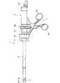
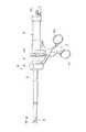
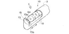
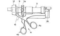
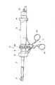
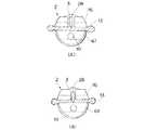
図1ないし図3は本発明の第1実施例に係り、図1は超音波切開凝固装置の概略構成を示す説明図、図2は超音波切開凝固装置の先端部分の構成を説明する拡大図、図3は図2のA矢視図であり、超音波切開凝固装置の作用を説明する図である。
【0012】
図1に示すように超音波切開凝固装置1は、可動部2と、この可動部2を体腔内に挿入するための後述する超音波プローブを被覆する保護部材であるシースで形成された挿入部3と、前記可動部2を操作する固定操作ハンドル4a及び可動操作ハンドル4bを有する操作部4と、前記可動部2に必要な超音波振動を供給する超音波振動子(不図示)を内蔵した振動子ユニット5とで構成されている。なお、符号11は後述する回動操作手段を構成する操作リングであり、符号12は後述する回転リングである。
【0013】
前記可動部2は、挿入部3の先端部に位置している。前記挿入部3に形成されている中空な内部には超音波プローブ6が挿通されており、振動子ユニット5の超音波振動子で発生した超音波振動が挿入部3の先端部から突出する超音波プローブ6によって可動部2に伝達されるようになっている。そして、前記超音波プローブ6の先端面に把持部材7が対向している。また、前記把持部材7には切開部7aと凝固面7bとの2つの処置部が形成されている。さらに、前記把持部材7を囲むように挿入部3の先端側にガード部材8が設けられている。このため、前記把持部材7の処置部が不用意に生体組織に接触することを防止している。
【0014】
前記超音波プローブ6は、操作部4の可動操作ハンドル4bを操作することにより進退するようになっている。すなわち、可動操作ハンドル4bの操作に対応して駆動ピン9が長手方向に進退する。すると、この駆動ピン9に係合している前記振動子ユニット5の外周に配設されている駆動リング5aが進退して振動子ユニット5が長手方向に対して進退する。このことによって超音波プローブ6の先端面6aが可動部2を進退する。
【0015】
前記可動操作ハンドル4bの操作によって超音波プローブ6の先端面6aが進退することによって、この超音波プローブ6と前記把持部材7との間の距離が可変して前記超音波プローブ6と前記把持部材7との間に位置する生体組織が把持されたり、開放されたりするようになっている。
【0016】
図2Aに示すように長手方向に進退自在な超音波プローブ6の先端面6a及び側面6bには処置する生体組織の洗浄や血液を吸引を行うための複数の送水・吸引孔10,10...が設けられている。そして、前記振動子ユニット5の後端に設けられている送水・吸引口金5bに図示しない送水・吸引手段を接続することにより、これら送水・吸引孔10,10...を介して送水・吸引が可能になっている。
【0017】
前記把持部材7は、前記挿入部3の外周面に配置されている操作リング11を長手方向に進退駆動させることにより、図2Aの一点鎖線に示す軸を中心にして矢印に示すように回動するようになっている。すなわち、術者が操作リング11を操作することによって、前記把持部材7の切開部7aと凝固面7bとを自由に選択することができるようになっている。
【0018】
なお、前記挿入部3の外周面に設けられている回転リング12を操作部4に対して回動操作することにより挿入部3が回動動作する。このことにより、前記挿入部3の先端に位置する可動部2の操作部4に対する位置を所望の向きに変えて生体組織の処置を容易に行うことができるようになっている。
【0019】
図3A及び図3Bを参照して上述のように構成されている超音波切開凝固装置1の作用を説明する。
まず、超音波切開凝固装置1の操作リング11を挿入部3の先端側方向にスライドさせて把持部材7を回動させて、この把持部材7の1つの処置部である凝固面7bを超音波プローブ6の先端面6aに対向させる。
【0020】
次に、同図Aに示すように処置すべく生体組織13を超音波プローブ6の先端面6aと把持部材7の凝固面7bとの間に把持するために、前記超音波切開凝固装置1の可動操作ハンドル4bを操作して生体組織を把持する。この状態で、超音波振動子駆動電源により振動子ユニット5の図示しない超音波振動子を駆動して超音波を発生させる。前記振動子ユニット5で発生した超音波振動は、超音波プローブ6を介して超音波プローブ6の先端面6aと把持部材7の凝固面7bとの間に把持されている生体組織13に伝達され、摩擦熱を発生して生体組織13を凝固する。
【0021】
次いで、可動操作ハンドル4bを一旦把持状態を開放するように操作して、前記超音波プローブ6を把持部材7に対して後退させ、生体組織13を把持する力量を減少させる。このとき、前記操作リング11を挿入部3の後方側方向にスライドさせて把持部材7のもう1つの処置部である切開部7aを超音波プローブ6の先端面6aに対向させる。
【0022】
続いて、同図Bに示すように、再び前記可動操作ハンドル4bを操作して超音波プローブ6の先端面6aを把持部材側に前進させ、生体組織13を把持部材7の切開部7aと超音波プローブ6の先端面6aとで把持する。この状態で、上述のように超音波プローブ6を介して生体組織13に超音波振動を与えると共に、可動操作ハンドル4bをさらに操作して生体組織13を把持する把持力量を増加させて超音波プローブ6の先端面6aを切開部7aに近づけていくことにより、生体組織13から出血させることなく切開が完了する。
【0023】
なお、上述のように予め凝固手順が必要ない場合や、切開手順が必要ない場合には、一方の処置部を超音波プローブの先端面に対向させた状態で単独操作することによって、生体組織13の凝固処置あるいは切開処置だけを行うようにしてもよい。
【0024】
また、上述の実施例において、把持部材7の外周面を切開部7aと凝固面7bとの2つ処置部で形成したが、把持部材7の外周面には必要に応じて図2Bに示すように切開部7a及び表面が滑らかな凝固面7bの他に、表面を凹凸状に形成した把持面7cを設けるなど、目的に応じた面を形成するようにしても良い。
【0025】
このように、切開部と凝固面とが複合した複雑な形状を把持部材に形成したことにより、超音波振動が伝達される超音波プローブの先端部の形状が単純形状にすることができる。
【0026】
また、超音波プローブの先端部の形状を単純化したことにより、破壊ひずみや破壊強度を高く保てるヤング率が低く生体適合性のある加工の難しいチタン材を用いて安価な超音波プローブを提供することができるので、超音波切開凝固装置を安価にして医療費の削減に貢献することができる。
【0027】
さらに、回動自在な把持部材がガード部材によって覆われているので、把持部材が不用意に生体組織を損傷することが無くなり安全性が向上する。
【0028】
また、一方の手の例えば親指で可動操作ハンドルを操作し、人差し指で回転リングと操作リングとを操作すると共に、中指と薬指で固定操作ハンドルを保持して片手での操作が可能になると共に、もう片方の手で他の鉗子の操作を行うことができるので術者の手術効率を大幅に向上させることができる。
【0029】
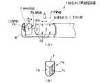
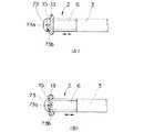
図4ないし図6は本発明の第2実施例に係り、図4は超音波切開凝固装置の概略構成を示す説明図、図5は超音波切開凝固装置の先端部分の構成を説明する拡大図、図6は図5のB矢視図であり、超音波切開凝固装置の作用を説明する図である。
【0030】
図4に示すように本実施例の超音波切開凝固装置1Aは、可動部2と、この可動部2を体腔内に挿入するための挿入部3と、前記可動部2を操作する固定操作ハンドル4a及び可動操作ハンドル4bを有する操作部4と、前記可動部2に超音波振動を供給する超音波振動子(不図示)を内蔵した振動子ユニット5とで構成されており、本実施例では挿入部3の先端部3aからは超音波プローブ61が突出すると共に、把持部材71が突出して可動部2を形成している。
【0031】
図5に示すように前記可動部2は、前記挿入部3の先端部に位置している。前記挿入部3の中空な内部には振動子ユニット5から供給される超音波振動を伝達する超音波プローブ61が挿通されており、この超音波プローブ61の先端部分が挿入部3の先端部3aより突出している。この超音波プローブ61の突出量は、前記振動子ユニット5に固定されている固定リング14を緩めて振動子ユニット5を長手方向に移動させることによって調節することができるようになっている。なお、前記超音波プローブ61の先端面及び図示されていない底面には前記第1実施例と同様に送水・吸引孔10,10...が設けられており、振動子ユニット5の送水・吸引口金5bに接続される送水・吸引手段によって処置する生体組織の洗浄や血液の吸引などができるようになっている。
【0032】
一方、前記超音波プローブ61の処置面6cに対向するように把持部材71が前記挿入部3の先端部3aにピン3bによって回動自在に軸支されている。前記把持部材71は、可動操作ハンドル4bを操作することにより前記超音波プローブ61の処置面6cに対して回動動作するようになっている。すむわち、可動操作ハンドル4bの操作に対応して駆動ピン9が長手方向に進退する。すると、この駆動ピン9に係合している前記振動子ユニット5の外周に配設されている駆動リング5aが進退し、この駆動リング5aの進退に応じて挿入部内に挿通されている図示しない駆動軸が進退して把持部材71が超音波プローブ61に対して開閉動作を行うようになっている。
【0033】
前記把持部材71の凝固面71bには凸状の切開部71aが形成されており、凝固面71bの前記切開部以外の部分に切開部71aの高さと同程度の厚さを有する弾性部材15が配設されている。
【0034】
なお、前記弾性部材15の弾性率は、生体組織13に応じて自由に設定することができるようになっている。その他の構成は前記第1実施例と同様であり、同部材には同符号を付して説明を省略する。
【0035】
図6A及び図6Bを参照して上述のように構成されている超音波切開凝固装置1Aの作用を説明する。
まず、同図Aに示すように可動操作ハンドル4bを操作して、超音波プローブ61と把持部材71との間に生体組織13が脱落しない程度の強さで把持する。このとき、把持部材71に設けられている弾性部材15は変形していないので、生体組織13には略平面状の弾性部材15と超音波プローブ61の処置面6cとで把持されている。
【0036】
次に、超音波振動子駆動電源により振動子ユニット5の図示しない超音波振動子を駆動させ、超音波プローブ61を介してに超音波振動を弾性部材15と超音波プローブ61の処置面6cとで把持されている生体組織13に伝達して凝固させる。
続いて、前記生体組織13を切開する場合には、超音波振動を伝達した状態で更に可動操作ハンドル4bを操作して把持部材71を超音波プローブ6の処置面側に移動させていく。すると、生体組織13に伝わる把持力量が増加して、同図Bに示すように把持力量の増加に伴い弾性部材15が圧縮変形して切開部71aが弾性部材15から露出し、この切開部71aで生体組織13に超音波振動を与えて出血させることなく切開を行う。
【0037】
なお、予め凝固させる必要がないときには、超音波振動を与えた状態で生体組織13を把持する把持力量を増加させて、凝固と切開とを同時に行うようにしても良い、また、切開しない場合には軽く把持したままの状態で超音波振動を与えて凝固処置だけが行える。
【0038】
このように、弾性部材の弾性率と可動操作ハンドルの操作力量を調節することにより、凝固処置と切開処置とを自在に切り替えのことができるので、凝固または切開を別々に行うことや凝固と切開とを同時に行うことができるので手術効率を大幅に向上させることができる。
【0039】
また、把持部材に設けた切開部は、術者が切開部を露出させるために可動操作ハンドルを操作したときにだけ露出するようになっているので、把持部材に設けた切開部によって不用意に他の生体組織を損傷することがなくなるので安全性も大幅に向上する。その他の作用及び効果は前記第1実施例と同様である。
【0040】
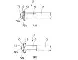
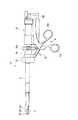
図7ないし図9は本発明の第3実施例に係り、図7は超音波切開凝固装置の概略構成を示す説明図、図8は超音波切開凝固装置の先端部分の構成を説明する拡大図、図9は図8のC矢視図であり、超音波切開凝固装置の作用を説明する図である。
【0041】
図7に示すように本実施例の超音波切開凝固装置1Bは、可動部2と、この可動部2を体腔内に挿入するための挿入部3と、前記可動部2を操作するための操作部4と、可動部2に超音波振動を供給する振動子ユニット5から構成されている。
【0042】
図8に示すように本実施例の超音波切開凝固装置1Bでは、把持部材72が挿入部3の先端に、前記挿入部3から突出する超音波プローブ先端面6aに対向して設けられている。そして、前記把持部材72の超音波プローブ6の先端面6aに対向する凝固面72bには前記第2実施例と同様に切開部72aと弾性部材15とが設けられている。その他の構成は前記第1実施例と同様であり、同部材には同符号を付して説明を省略する。
【0043】
図9A及び図9Bを参照して上述のように構成されている超音波切開凝固装置1Bの作用を説明する。
まず、同図Aに示すように可動操作ハンドル4bを操作して、超音波プローブ6の先端面6aと把持部材72の弾性部材15との間に生体組織13を脱落しない程度の強さで把持する。ここで、図示しない超音波振動子を駆動させ、超音波プローブ6を介して超音波振動を前記超音波プローブ6の先端面6aと把持部材72の弾性部材15との間に把持された生体組織13に伝達して凝固させる。
【0044】
続いて、生体組織13を切開する場合には、超音波振動を与えてた状態で更に可動操作ハンドル4bを操作して超音波プローブ6を把持部材側に前進させて、生体組織13にかかる把持力量を増加させいく。すると、同図Bに示すように把持力量の増加に伴い弾性部材15が圧縮変形して切開部72aが露出し、この切開部72aで生体組織13に超音波振動を与えて出血させることなく切開を行う。
【0045】
このように、長手方向に進退する超音波プローブが把持力量になるので、可動操作ハンドルを操作したときの力量が超音波プローブに直接伝わって把持力量を術者が容易に把握することができるので操作性が向上する。その他の作用及び効果は上述の実施例と同様である。
【0046】
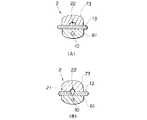
図10ないし図12は本発明の第4実施例に係り、図10は超音波切開凝固装置の概略構成を示す説明図、図11は超音波切開凝固装置の先端部分の構成を説明する拡大図、図12は図11のD矢視図であり、超音波切開凝固装置の作用を説明する図である。
【0047】
図10に示すように本実施例の超音波切開凝固装置1の基本構成は、前記第2実施例とほぼ同様であり、可動部2と、この可動部2をを体腔内に挿入するための挿入部3と、前記可動部2を操作する操作部4などから構成されており、挿入部3の先端部3aからは超音波プローブ61が突出すると共に、把持部材73が突出して可動部2を形成している。
【0048】
図11に示すように前記可動部2には、前記挿入部3の中空な内部を挿通して振動子ユニット5から供給される超音波振動を伝達する超音波プローブ61が突出している。この超音波プローブ61の突出量は、前記振動子ユニット5に固定されている固定リング14を緩めて振動子ユニット5を長手方向に移動させることにより調節することができるようになっている。また、超音波プローブ61の先端面及び底面には送水・吸引孔10,10...が開口しており、振動子ユニット5に設けられている送水・吸引口金5bに接続される図示しない送水・吸引手段によって処置する生体組織の洗浄や血液の吸引などができるようになっている。
【0049】
一方、前記超音波プローブ61の処置面61cに対向するように把持部材73が前記挿入部3の先端部3aにピン3bによって回動自在に軸支されている。前記把持部材73は、可動操作ハンドル4bを操作することにより前記超音波プローブ61の処置面61cに対して回動動作するようになっている。前記把持部材73の凝固面73bには切開部を形成するカットワイヤー21が摺動して配設される溝22が設けられている。
【0050】
前記溝22に摺動自在に配設されるカットワイヤー21は、操作部4に設けられているレバー16を操作することにより、溝内部を長手方向に進退するようになっている。なお、前記カットワイヤー21は、通常状態では凝固面73bよりも手元側の挿入部内に格納されている。その他の構成は前記第1実施例と同様であり、同部材には同符号を付して説明を省略する。
【0051】
図12A及び図12Bを参照して上述のように構成されている超音波切開凝固装置1Cの作用を説明する。
まず、同図Aに示すように可動操作ハンドル4bを操作して、超音波プローブ61の処置面61cと把持部材73との間に生体組織13を把持する。ここで、図示しない超音波振動子を駆動させて超音波プローブ61に超音波振動を超音波プローブ61の処置面61cと把持部材73との間に把持されている生体組織13に伝達して凝固させる。
【0052】
次に、レバー16を手元側に操作することにより、同図Bに示すようにカットワイヤー21を把持部材73の溝内部を先端側に移動させて凝固面73bからカットワイヤヤー21を露出させ、超音波振動を与えることにより出血させることなく生体組織13を切開する。
【0053】
このとき、予め凝固を行う必要がないときには、カットワイヤー21を初めから凝固面73bから露出させた状態にして、凝固させると同時に切開を行えるようにしても良い。また、切開の必要が無い場合にはカットワイヤー21を収納したままの状態で凝固処置のみを行うようにしても良い。
【0054】
このように、処置部材に形成した溝内部を摺動するカットワイヤーを必要に応じて凝固面から露出させて目的の処置を行うことができるので、不用意に生体組織を損傷することなく安全性が大幅に向上する。その他の作用及び効果は上述の実施例と同様である。
【0055】
図13ないし図15は本発明の第5実施例に係り、図13は超音波切開凝固装置の概略構成を示す説明図、図14は超音波切開凝固装置の先端部分の構成を説明する拡大図、図15は図14のE矢視図であり、超音波切開凝固装置の作用を説明する図である。
【0056】
図13に示すように本実施例の超音波切開凝固装置1Dは、可動部2と、この可動部2を体腔内に挿入するための挿入部3と、前記可動部2を操作するための操作部4と、可動部2に超音波振動を供給する振動子ユニット5から構成されている。
【0057】
図14に示すように可動部2は、挿入部3の先端側に位置しており、前記挿入部3の中空な内部を挿通して振動子ユニット5から供給される超音波振動を伝達する超音波プローブ6が前記挿入部3から突出している。
【0058】
また、前記操作部4の可動操作ハンドル4bを操作することにより駆動ピン9が進退移動し、この駆動ピン9に係合している振動子ユニット5の外周に設けられた駆動リング5aが進退することにより挿入部3の外筒管の進退に伴い把持部材73が進退し、超音波プローブ6の先端面6aとの間に生体組織を把持したり、開放することができるようになっている。
【0059】
なお、前記超音波プローブ6の先端面6a及び側面62bには送水・吸引孔10,10...が開口しており、振動子ユニット5に設けられている送水・吸引口金5bに接続される図示しない送水・吸引手段により処置をする生体組織の洗浄や血液の吸引が可能になっている。
【0060】
また、前記把持部材73の凝固面73bには切開部73aが凸状に形成されており、凝固面73bの切開部73a以外の部分には切開部73aの高さと同程度の厚さを有する弾性部材15が配設されている。その他の構成は前記3実施例と同様であり同部材には同符号を付して説明を省略する。
【0061】
図15A及び図15Bを参照して上述のように構成されている超音波切開凝固装置1Dの作用を説明する。
まず、同図Aに示すように可動操作ハンドル4bを操作して把持部材73を後退させて、この把持部材73の弾性部材15と超音波プローブ6の先端面6aとの間に生体組織13が脱落しない程度の強さで把持する。この状態で、図示しない超音波振動子を駆動させて超音波プローブ6を介して超音波振動を前記把持部材73の弾性部材15と超音波プローブ6の先端面6aとの間に把持されている生体組織13に伝達して凝固させる。
【0062】
続いて、生体組織13を切開する場合には、可動操作ハンドル4bをさらに操作して把持部材73を超音波プローブ6の先端面側に後退させて生体組織13にかかる把持力量を増加させていく。すると、同図Bに示すように把持力量の増加に伴い弾性部材15が圧縮変形して切開部73aが露出し、超音波振動を与えることにより生体組織13を出血させることなく切開する。このことにより、前記第2実施例及び第3実施例と同様の作用及び効果を得ることができる。
【0063】
図16ないし図18は本発明の第6実施例に係り、図16は超音波切開凝固装置の概略構成を示す説明図、図17は超音波切開凝固装置の先端部分の構成を説明する拡大図、図18は図17のF矢視図であり、超音波切開凝固装置の作用を説明する図である。
【0064】
図16に示すように本実施例の超音波切開凝固装置1Eの基本構成は、前記第3実施例と略同様であり、可動部2と、この可動部2を体腔内に挿入するための挿入部3と、前記可動部2を操作するための操作部4などで構成されている。
【0065】
図17に示すように超音波切開凝固装置1Eでは、把持部材74の凝固面74aが挿入部3の先端に、前記挿入部3から突出する超音波プローブ先端面6aに対向して設けられている。前記凝固面74aには切開部を形成するカットワイヤー21が摺動配設されるための溝23が形成されている。前記カットワイヤー21は、操作部4に設けられているレバー16を操作することにより挿入部内を進退自在になっており、可動部2の把持部材74の凝固面74aに設けた溝23において上下方向に摺動移動するようになっている。
【0066】
なお、前記カットワイヤー21は、通常状態では可動部2よりも手元側に位置する挿入部内に格納されている。その他の構成は上述の実施例と同様であり、同部材には同符号を付して説明を省略する。
【0067】
図18A,図18B及び図18Cを参照して上述のように構成されている超音波切開凝固装置1Eの作用を説明する。
まず、同図Aに示すように可動操作ハンドル4bを操作して、超音波プローブ6の先端面6aと把持部材74の凝固面74aとの間に生体組織13を把持する。ここで、図示しない超音波振動子を駆動させて超音波プローブ6を介して超音波振動を超音波プローブ6の先端面6aと把持部材74の凝固面74aとの間に把持されている生体組織13に伝達して凝固させる。
【0068】
次に、レバー16を手元側に操作することにより、同図Bに示すようにカットワイヤー21を把持部材74の溝23の内部を摺動移動させて凝固面74aからカットワイヤ21を露出させる。
【0069】
続いて、同図Cに示すように可動操作ハンドル4bをさらに操作して、前記超音波プローブ6を把持部材側に移動させて生体組織13を把持する把持力量力を増加させていくと共に、超音波振動を与えることにより、生体組織13から出血させることなく切開する。
【0070】
このとき、予め凝固する必要がないときには、カットワイヤー21を初めから凝固面74aから露出させておいて凝固と同時に切開を行うようにしても良い。また、切開処置を行わない場合にはカットワイヤー21を収納したままの状態にして凝固処置のみを行うようにしても良い。このことにより、上述の実施例と同様の作用及び効果を得ることができる。
【0071】
図19ないし図21は本発明の第7実施例に係り、図19は超音波切開凝固装置の概略構成を示す説明図、図20は超音波切開凝固装置の先端部分の構成を説明する拡大図、図21は図20のG矢視図であり、超音波切開凝固装置の作用を説明する図である。
【0072】
図19に示すように本実施例の超音波切開凝固装置1Fは、可動部2と、この可動部2を体腔内に挿入するための挿入部3と、前記可動部2を操作するための操作部4と、前記可動部2に超音波振動を供給する振動子ユニット5などで構成されている。
【0073】
図20に示すように本実施例の超音波切開凝固装置1Fでは、把持部材75が挿入部3の先端に、前記挿入部3から突出する超音波プローブ62の先端面62aに対向して設けられている。前記超音波プローブ6は、操作部4の可動操作ハンドル4bを操作することにより進退するようになっている。
【0074】
前記超音波プローブ62は、中空構造であり、この中空部分にはカッター25が挿通されている。このカッター25は、超音波プローブ63とは独立して可動するようになっており、レバー16を操作することによってカッター駆動部材26が連動して前進することによってカッター25を前進させるようになっている。一方、前記レバー16を逆方向に操作することによって、カッター駆動部材26が連動して後退することによってカッター25が後退するようになっている。その他の構成は前述の実施例と同様であり同部材には同符号を付して説明を省略する。
【0075】
図21A及び図21Bを参照して上述のように構成されている超音波切開凝固装置1Fの作用を説明する。
同図Aに示すように生体組織13を把持する場合には可動操作ハンドル4bを操作して超音波プローブ62を把持部材側に移動させ、超音波プローブ62の先端面62aと把持部材75との間に把持する。そして、振動子ユニット5の超音波振動子を駆動させて超音波プローブ62を介して超音波振動を超音波プローブ62の先端面62aと把持部材75との間に把持された生体組織13に伝達して凝固させる。
【0076】
続いて、レバー16を操作する。すると同図Bに示すようにカッター25が超音波プローブ62の内部を移動して超音波プローブ先端面62aから突出する。ここで、超音波振動を伝達しながら前記レバー16を操作してさらにカッター25を把持部材側に移動させて生体組織13より出血させることなく切開する。
【0077】
このとき、予め凝固処置が必要ない場合や、逆に切開処置が必要ない場合にはそれぞれ単独の操作により、生体組織13を凝固、切開するなどの処置を行うようにしてもよい。また、連続して凝固と切開を行う場合には図22に示すようにレバー16を用いる代わりに操作部4内にカム機構など駆動機構(不図示)を用い例えば、可動操作ハンドル4bを一段階操作すると超音波プローブ62が前進して生体組織13を把持し、さらにもう一段階操作すると超音波プローブ62の位置が変わらずにカッター25だけが前進して生体組織13を切開するような構造にしても良い。さらに、超音波プローブ62を図23に示すように先端部部分を板状部62dを設けて、凝固と切開の両方を行えるようにしてもよい。
【0078】
このように、レバーと可動操作ハンドルとをそれぞれ操作することによってカッターと超音波プローブとの操作を行うことができるので手術効率が向上する。また、カッターが使用時以外には超音波プローブ内に収納された状態になっているので、不用意に生体組織を損傷する危険がなくなり、安全性が向上する。その他の作用及び効果は上述の実施例と同様である。
【0079】
図24ないし図26は本発明の第8実施例に係り、図24は超音波切開凝固装置の概略構成を示す説明図、図25は超音波切開凝固装置の先端部分の構成を説明する拡大図、図25は図24のH矢視図であり、超音波切開凝固装置の作用を説明する図である。
【0080】
図24に示すように本実施例の超音波切開凝固装置1Gは、可動部2と、可動部2を体腔内に挿入するための挿入部3と、前記可動部2を操作するための操作部4と、可動部2に超音波振動を供給する振動子ユニット5から構成されている。
【0081】
図25に示すように可動部2は、挿入部3の先端側に位置しており、中空の挿入部3の内部を挿通した振動子ユニット5から超音波振動を伝達する超音波プローブ61が挿入部3の先端部から突出している。この超音波プローブ61の処置面61cに対向するように把持部材76とカッター28とが前記挿入部3の先端部3aにピン3bによって回動自在に軸支されている。また、操作部4の可動操作ハンドル4bの開閉操作により駆動ピン9が進退移動し、この駆動ピン9に噛合している駆動リング5aが進退駆動されて図示しない駆動軸が進退駆動され、図示しないカム機構により把持部材76と把持部材76の中間に設けられているカッター28が開閉動作する。すなわち、超音波プローブ61の処置面61cと把持部材76との間に生体組織13を把持したり開放すると共に、切開処置を行うことができるようになっている。その他の構成は前述の実施例と同様であり、同部材には同符号を付して説明を省略する。
【0082】
図26A及び図26Bを参照して上述のように構成されている超音波切開凝固装置1Gの作用を説明する。
まず、同図Aに示すように生体組織13を超音波プローブ61の処置面61cと把持部材79との間に把持するため可動操作ハンドル4bを一段階操作して把持部材79だけを処置面側に回動させて生体組織13を把持する。そして、振動子ユニット5の図示しない超音波振動子を駆動させて超音波プローブ61を介して超音波振動を超音波プローブ61の処置面61cと把持部材79との間に把持されている生体組織13に伝達して凝固させる。このとき、カッター28は、把持部材79の内部に格納された状態になっている。
【0083】
続いて、可動操作ハンドル4bをもう一段階操作することにより、図示しないカム機構によりカッター28を把持部材7を処置面側に回動される。同図Bに示すようにこのとき実質的にカッター28と超音波プローブ61とにより生体組織13が把持された状態になり、超音波振動を加えることにより生体組織13を出血させることなく切開する。このことにより、前記第7実施例と同様の作用及び効果を得ることができる。
【0084】
なお、前記第7実施例のように把持部材とカッターとを別々に操作したければ、可動操作ハンドル4bの他にカッター28を操作するための操作手段として前記レバー16を設ければ良い。
【0085】
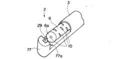
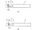
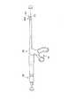
図27ないし図29は本発明の第9実施例に係り、図27は超音波切開凝固装置の概略構成を示す説明図、図28は超音波切開凝固装置の先端部分の構成を説明する拡大図、図29は図28のI矢視図であり、超音波切開凝固装置の作用を説明する図である。
【0086】
図27に示すように本実施例の超音波切開凝固装置1Hの主要構成は第5実施例とほぼ同様であるが、操作部4にレバー16が備わっており、このレバー16を操作することにより図28に示すように可動部2に設けられているカッター29が凝固面77aを進退駆するようになっている。その他の構成は上述の実施例と同様であり同部材には同符号を付して説明を省略する。
【0087】
図29A及び図29Bを参照して上述のように構成されている超音波切開凝固装置1Hの作用を説明する。
まず、同図Aに示すように可動操作ハンドル4bを操作して生体組織13を超音波プローブ6の先端面6aと把持部材77との間に把持する。ここで、振動子ユニット5の図示しない超音波振動子を駆動させて超音波プローブ61を介して超音波振動を前記超音波プローブ6の先端面6aと把持部材77との間に把持されている生体組織13に伝達して凝固させる。
【0088】
続いて、生体組織13を切開する場合は、上述の状態でレバー16を操作してカッター29を凝固面77aより突出させ、振動子ユニット5の超音波振動子を駆動させて超音波プローブ6を介して超音波振動を超音波プローブ6の先端面6aとカッター29との間の生体組織13に伝達して生体組織13を出血させることなく切開する。
【0089】
このとき、予め凝固する必要がない場合にはカッター29を凝固面77aより突出させておいて凝固と切開とを同時に行うようにしても良い。また、切開しない場合には把持部材77の凝固面77aからカッター29を突出させること無く凝固のみを行っても良い。さらに、凝固を行いながらカッター28を用いることにより凝固処置と同時に切開処置を行うようにしても良い。このことにより、上述の第8実施例と同様の作用及び効果を得ることができる。
【0090】
以上示したように把持部材に少なくとも凝固用の凝固面部と切開用の切開部との2つが備わるという本願の目的に沿った範囲であれば、超音波切開凝固装置の構造は上述のものに限定されない。また、凝固と切開とを切り替えることなく、凝固と切開とを行えるという本願の目的の範囲であれば、超音波切開凝固装置の構造は上述のものに限定されない。
【0091】
[付記]
1.把持部を形成する超音波振動子を内蔵した振動子ユニットと、
前記超音波振動子で発生する超音波振動を前記振動子ユニットの最先端に位置する可動部に伝達する超音波プローブと、
この超音波プローブを被覆する保護部材であるシースで形成された挿入部と、
生体組織を前記可動部で把持するための把持部材と、
前記可動部で生体組織を把持したり、この把持された生体組織の開放を行う操作部とを有する超音波切開凝固装置において、
前記可動部の超音波プローブ先端面との間で生体組織を把持する把持部材に、少なくとも生体組織との接触面積が広く超音波振動により前記生体組織を凝固する凝固面と、生体組織との接触面積が狭く超音波振動により前記生体組織を切開する切開部とを設けた超音波切開凝固装置。
【0092】
2.前記把持部材の把持面側に弾性部材を設け、この弾性部材で切開部が覆われている付記1記載の超音波切開凝固装置。
【0093】
3.前記把持部材と前記超音波プローブ先端面との間に把持した生体組織を強く把持した際、前記弾性部材が弾性変形して切開部が露出する付記1及び付記2記載の超音波切開凝固装置。
【0094】
4.前記操作部を操作することにより前記超音波プローブが前記把持部材に対して進退して生体組織を把持または開放する付記1記載の超音波切開凝固装置。
【0095】
5.前記操作部を操作することにより前記把持部材が前記超音波プローブに対して進退して生体組織を把持または開放する付記1記載の超音波切開凝固装置。
【0096】
6.前記把持部材が前記超音波プローブの進退方向に対して垂直な軸を中心に回動自在で、この把持部材を回動させるための回動操作手段を有する付記1及び付記4記載の超音波切開凝固装置。
【0097】
7.前記回動操作手段を操作することにより前記超音波プローブの先端面に対して凝固面部と切開部とを対向させる付記6記載の超音波切開凝固装置。
【0098】
8.前記回動操作手段が選択的に使用可能である付記6記載の超音波切開凝固装置。
【0099】
9.前記把持部材の把持面に切開部となる切開部材を配設するための溝を設けた付記1記載の超音波切開凝固装置。
【0100】
10.前記溝内に配設される切開部材が、進退操作手段によって溝内を進退する付記9記載の超音波切開凝固装置。
【0101】
11.前記進退操作手段が選択的に使用可能である付記10記載の超音波切開凝固装置。
【0102】
【発明の効果】
以上説明したように本発明によれば、超音波プローブを回動操作することなく生体組織を凝固あるいは切開可能で、超音波プローブのプローブ形状が単純な操作性に優れた超音波切開凝固装置を提供することができる。
【図面の簡単な説明】
【図1】図1ないし図3は本発明の第1実施例に係り、図1は超音波切開凝固装置の概略構成を示す説明図
【図2】超音波切開凝固装置の先端部分の構成を説明する拡大図
【図3】図2のA矢視図であり、超音波切開凝固装置の作用を説明する図
【図4】図4ないし図6は本発明の第2実施例に係り、図4は超音波切開凝固装置の概略構成を示す説明図
【図5】超音波切開凝固装置の先端部分の構成を説明する拡大図
【図6】図5のB矢視図であり、超音波切開凝固装置の作用を説明する図
【図7】図7ないし図9は本発明の第3実施例に係り、図7は超音波切開凝固装置の概略構成を示す説明図
【図8】超音波切開凝固装置の先端部分の構成を説明する拡大図
【図9】図8のC矢視図であり、超音波切開凝固装置の作用を説明する図
【図10】図10ないし図12は本発明の第4実施例に係り、図10は超音波切開凝固装置の概略構成を示す説明図
【図11】超音波切開凝固装置の先端部分の構成を説明する拡大図
【図12】図11のD矢視図であり、超音波切開凝固装置の作用を説明する図
【図13】図13ないし図15は本発明の第5実施例に係り、図13は超音波切開凝固装置の概略構成を示す説明図
【図14】超音波切開凝固装置の先端部分の構成を説明する拡大図
【図15】図14のE矢視図であり、超音波切開凝固装置の作用を説明する図
【図16】図16ないし図18は本発明の第6実施例に係り、図16は超音波切開凝固装置の概略構成を示す説明図
【図17】超音波切開凝固装置の先端部分の構成を説明する拡大図
【図18】図17のF矢視図であり、超音波切開凝固装置の作用を説明する図
【図19】図19ないし図21は本発明の第7実施例に係り、図19は超音波切開凝固装置の概略構成を示す説明図
【図20】超音波切開凝固装置の先端部分の構成を説明する拡大図
【図21】図20のG矢視図であり、超音波切開凝固装置の作用を説明する図
【図22】操作部の別の構成を示す図
【図23】可動部に配設される超音波プローブの別の構成を示す図
【図24】図24ないし図26は本発明の第8実施例に係り、図24は超音波切開凝固装置の概略構成を示す説明図
【図25】超音波切開凝固装置の先端部分の構成を説明する拡大図
【図26】図24のH矢視図であり、超音波切開凝固装置の作用を説明する図
【図27】図27ないし図29は本発明の第9実施例に係り、図27は超音波切開凝固装置の概略構成を示す説明図
【図28】超音波切開凝固装置の先端部分の構成を説明する拡大図
【図29】図28のI矢視図であり、超音波切開凝固装置の作用を説明する図
【図30】図30及び図31は従来例に係り、図30は超音波切開凝固装置の概略構成を示す説明図
【図31】超音波切開凝固装置の先端部分の構成を説明する拡大図
【符号の説明】
1…超音波切開凝固装置
2…可動部
3…挿入部
6…超音波プローブ
7…把持部材
7a…切開部
7b…凝固面[0001]
[Industrial application fields]
The present invention relates to an ultrasonic incision and coagulation apparatus for coagulating or excising a living tissue by ultrasonic vibration.
[0002]
[Prior art]
In recent years, by inserting an elongated endoscope into a body cavity, various internal organs and the like are observed, and various therapeutic treatments are performed under endoscopic observation as necessary.
[0003]
As one of the methods for performing a therapeutic treatment under the endoscopic observation, a living tissue is adsorbed or grasped, and ultrasonic vibration is applied to the adsorbing or grasping member to solidify or excise the living tissue. It is known to perform treatments.
[0004]
For example, Japanese Patent Laid-Open No. 62-127042 discloses an ultrasonic lithotripsy probe that holds a calculus and is crushed by ultrasonic vibration. JP-A-1-232944 discloses a surgical operation apparatus in which a living tissue is grasped and fixed with grasping forceps and incised with a probe that vibrates ultrasonically. Further, JP-A-1-232945 discloses a surgical operation apparatus in which a living tissue is adsorbed and fixed and incised by a scalpel that is ultrasonically vibrated. Japanese Laid-Open Patent Publication No. 1-223248 discloses a surgical excision forceps that can efficiently excise a living tissue by applying ultrasonic vibration to the excision forceps. Furthermore, in JP-A-1-232949, a surgical procedure in which a living tissue is fixed by a gripping means and treatment is applied to the living tissue by a movable member to which ultrasonic vibration is applied, as in JP-A-1-232944. A surgical device is shown.
[0005]
However, since the above-described prior art can only perform either incision or coagulation treatment on a living tissue, for example, a combined treatment such as incising a living tissue and coagulating a necessary site can be performed. There wasn't. In order to solve this problem, US Pat. No. 5,322,055 discloses a superstructure having a shape in which a knife-
[0006]
[Problems to be solved by the invention]
However, in the clamp coagulation apparatus and cutting system for an ultrasonic surgical instrument disclosed in the above-mentioned USP 5322055, when switching between a coagulation surface and an incision part during an operation, the grasped living tissue is opened at one end, The probe was rotating. For this reason, since it operates with both the hand which operates the operation means which grasps | releases a biological tissue, and the hand for performing rotation operation of an ultrasonic probe, usability was very bad.
[0007]
Moreover, the shape of the ultrasonic probe was complicated. Since an ultrasonic probe generally needs to keep high fracture strain and fracture strength, a titanium material is used as a biocompatible material with a low Young's modulus. However, since the titanium material is difficult to process and expensive, there is a problem that the ultrasonic probe becomes expensive if the probe shape is complicated.
[0008]
The present invention has been made in view of the above circumstances, and enables ultrasonic coagulation or incision of a living tissue without rotating the ultrasonic probe, and the ultrasonic probe has a simple probe shape and excellent operability. The object is to provide a coagulation device.
[0009]
[Means for Solving the Problems]
The present inventionbyThe ultrasonic incision coagulatorAn ultrasonic transducer that generates ultrasonic vibrations and,Connected to the ultrasonic transducerGenerated by the ultrasonic transducerdidUltrasonic vibrationToReaching an ultrasonic probe,Grasping and treating living tissue with the tip of the ultrasonic probeA gripping member;A coagulation portion provided on the gripping member, capable of coagulating the biological tissue by ultrasonic vibration generated by the ultrasonic transducer by gripping the biological tissue with the distal end portion of the ultrasonic probe;,An incision portion provided on the grasping member and capable of incising the living tissue by ultrasonic vibration generated by the ultrasonic transducer by grasping the living tissue with the tip portion of the ultrasonic probe;,And an operation means for switching between a coagulation operation for coagulating the living tissue between the distal end portion of the ultrasonic probe and the coagulation portion and an incision operation for incising the living tissue between the incision portion. Be.
[0010]
[Operation]
In the ultrasonic incision and coagulation apparatus of the present invention, when performing an incision treatment of a living tissue, the operation means is switched to the incision operation, and the living tissue is between the incision provided on the gripping member and the tip of the ultrasonic probe. The living tissue is incised by ultrasonic vibration generated by the ultrasonic vibrator. When coagulating the living tissue, the operation means is switched to the coagulation operation, the living tissue is grasped between the coagulating part provided on the grasping member and the tip of the ultrasonic probe, and the ultrasonic vibration is performed. The living tissue is coagulated by ultrasonic vibration generated in the child.
[0011]
【Example】
Embodiments of the present invention will be described below with reference to the drawings.
1 to 3 relate to a first embodiment of the present invention, FIG. 1 is an explanatory view showing a schematic configuration of an ultrasonic incision coagulation apparatus, and FIG. 2 is an enlarged view illustrating a configuration of a tip portion of the ultrasonic incision coagulation apparatus. FIG. 3 is a view taken in the direction of arrow A in FIG. 2 and is a view for explaining the operation of the ultrasonic incision and coagulation apparatus.
[0012]
As shown in FIG. 1, an ultrasonic incision and coagulation apparatus 1 includes a
[0013]
The
[0014]
The
[0015]
When the
[0016]
As shown in FIG. 2A, the
[0017]
The gripping
[0018]
The
[0019]
The operation of the ultrasonic incision and coagulation apparatus 1 configured as described above will be described with reference to FIGS. 3A and 3B.
First, the
[0020]
Next, in order to grasp the
[0021]
Next, the
[0022]
Subsequently, as shown in FIG. 7B, the
[0023]
In the case where the coagulation procedure is not necessary in advance or the incision procedure is not necessary as described above, the living
[0024]
Further, in the above-described embodiment, the outer peripheral surface of the gripping
[0025]
As described above, by forming a complicated shape in which the incision portion and the coagulation surface are combined in the gripping member, the shape of the tip portion of the ultrasonic probe to which ultrasonic vibration is transmitted can be made simple.
[0026]
In addition, by simplifying the shape of the tip of the ultrasonic probe, an inexpensive ultrasonic probe is provided using a titanium material that has a low Young's modulus and is biocompatible and difficult to process. Therefore, the ultrasonic incision and coagulation apparatus can be made inexpensive and contribute to the reduction of medical costs.
[0027]
Furthermore, since the rotatable gripping member is covered with the guard member, the gripping member does not inadvertently damage the living tissue, and safety is improved.
[0028]
In addition, the movable operation handle is operated with the thumb of one hand, for example, the rotation ring and the operation ring are operated with the index finger, the fixed operation handle is held with the middle finger and the ring finger, and the operation with one hand becomes possible. Since the other forceps can be operated with the other hand, the operation efficiency of the operator can be greatly improved.
[0029]
4 to 6 relate to a second embodiment of the present invention, FIG. 4 is an explanatory view showing a schematic configuration of the ultrasonic incision coagulation apparatus, and FIG. 5 is an enlarged view illustrating a configuration of a tip portion of the ultrasonic incision coagulation apparatus. FIG. 6 is a view taken in the direction of arrow B in FIG.
[0030]
As shown in FIG. 4, the ultrasonic incision coagulation apparatus 1 </ b> A according to the present embodiment includes a
[0031]
As shown in FIG. 5, the
[0032]
On the other hand, a gripping
[0033]
A
[0034]
The elastic modulus of the
[0035]
The operation of the ultrasonic incision and coagulation apparatus 1A configured as described above will be described with reference to FIGS. 6A and 6B.
First, as shown in FIG. 3A, the
[0036]
Next, an ultrasonic transducer (not shown) of the
Subsequently, when incising the
[0037]
When it is not necessary to coagulate in advance, the amount of grasping force for grasping the
[0038]
In this way, by adjusting the elastic modulus of the elastic member and the amount of operation force of the movable operation handle, it is possible to freely switch between the coagulation treatment and the incision treatment. Therefore, the surgical efficiency can be greatly improved.
[0039]
In addition, the incision provided in the gripping member is exposed only when the operator operates the movable operation handle to expose the incision. Safety is greatly improved because other living tissues are not damaged. Other operations and effects are the same as those of the first embodiment.
[0040]
FIGS. 7 to 9 relate to a third embodiment of the present invention, FIG. 7 is an explanatory view showing a schematic configuration of the ultrasonic incision and coagulation apparatus, and FIG. 8 is an enlarged view for explaining the configuration of the tip portion of the ultrasonic incision and coagulation apparatus. FIG. 9 is a view taken in the direction of the arrow C in FIG.
[0041]
As shown in FIG. 7, the ultrasonic incision and coagulation apparatus 1 </ b> B according to the present embodiment includes a
[0042]
As shown in FIG. 8, in the ultrasonic dissection and
[0043]
The operation of the ultrasonic incision and
First, as shown in FIG. 3A, the
[0044]
Subsequently, when the
[0045]
In this way, since the ultrasonic probe that advances and retreats in the longitudinal direction becomes the gripping force amount, the force amount when the movable operation handle is operated is directly transmitted to the ultrasonic probe, so that the operator can easily grasp the gripping force amount. Operability is improved. Other operations and effects are the same as those of the above-described embodiment.
[0046]
FIGS. 10 to 12 relate to a fourth embodiment of the present invention, FIG. 10 is an explanatory view showing a schematic configuration of the ultrasonic incision coagulation apparatus, and FIG. 11 is an enlarged view for explaining the configuration of the distal end portion of the ultrasonic incision coagulation apparatus. FIG. 12 is a view taken in the direction of arrow D in FIG. 11 and is a view for explaining the operation of the ultrasonic incision and coagulation apparatus.
[0047]
As shown in FIG. 10, the basic configuration of the ultrasonic incision and coagulation apparatus 1 of the present embodiment is substantially the same as that of the second embodiment, and a
[0048]
As shown in FIG. 11, an
[0049]
On the other hand, a gripping
[0050]
The
[0051]
The operation of the ultrasonic incision and coagulation apparatus 1C configured as described above will be described with reference to FIGS. 12A and 12B.
First, as shown in FIG. A, the movable operation handle 4 b is operated to hold the
[0052]
Next, by operating the
[0053]
At this time, when it is not necessary to perform coagulation in advance, the
[0054]
In this way, the cut wire that slides inside the groove formed in the treatment member can be exposed from the coagulation surface as necessary to perform the desired treatment, so safety without inadvertently damaging the living tissue Is greatly improved. Other operations and effects are the same as those of the above-described embodiment.
[0055]
FIGS. 13 to 15 relate to a fifth embodiment of the present invention, FIG. 13 is an explanatory view showing a schematic configuration of the ultrasonic incision coagulation apparatus, and FIG. 14 is an enlarged view for explaining the configuration of the distal end portion of the ultrasonic incision coagulation apparatus. 15 is a view taken in the direction of arrow E in FIG. 14 and is a view for explaining the operation of the ultrasonic incision and coagulation apparatus.
[0056]
As shown in FIG. 13, the ultrasonic incision and coagulation apparatus 1 </ b> D of this embodiment includes a
[0057]
As shown in FIG. 14, the
[0058]
Further, by operating the
[0059]
Note that the water supply / suction holes 10, 10. . . Is opened, and it is possible to clean the living tissue and suck blood by performing treatment with water / suction means (not shown) connected to the water /
[0060]
In addition, an
[0061]
The operation of the ultrasonic incision and coagulation apparatus 1D configured as described above will be described with reference to FIGS. 15A and 15B.
First, as shown in FIG. A, the
[0062]
Subsequently, when incising the
[0063]
FIGS. 16 to 18 relate to the sixth embodiment of the present invention, FIG. 16 is an explanatory view showing a schematic configuration of the ultrasonic incision coagulation apparatus, and FIG. 17 is an enlarged view for explaining the configuration of the distal end portion of the ultrasonic incision coagulation apparatus. FIG. 18 is a view taken in the direction of arrow F in FIG. 17 and is a diagram for explaining the operation of the ultrasonic incision and coagulation apparatus.
[0064]
As shown in FIG. 16, the basic configuration of the ultrasonic incision and
[0065]
As shown in FIG. 17, in the ultrasonic
[0066]
Note that the
[0067]
The operation of the ultrasonic dissection and
First, as shown in FIG. 3A, the
[0068]
Next, by operating the
[0069]
Subsequently, as shown in FIG. 3C, the
[0070]
At this time, when it is not necessary to coagulate in advance, the
[0071]
19 to 21 relate to a seventh embodiment of the present invention, FIG. 19 is an explanatory view showing a schematic configuration of the ultrasonic incision coagulation apparatus, and FIG. 21 is a view taken in the direction of the arrow G in FIG. 20, and is a view for explaining the operation of the ultrasonic incision and coagulation apparatus.
[0072]
As shown in FIG. 19, the ultrasonic incision and coagulation apparatus 1 </ b> F according to the present embodiment includes a
[0073]
As shown in FIG. 20, in the ultrasonic incision and coagulation apparatus 1 </ b> F of the present embodiment, a gripping
[0074]
The
[0075]
The operation of the ultrasonic incision and
As shown in FIG. A, when the
[0076]
Subsequently, the
[0077]
At this time, when a coagulation treatment is not necessary or when an incision treatment is not necessary, a treatment such as coagulation or incision of the
[0078]
As described above, the operation of the cutter and the ultrasonic probe can be performed by operating the lever and the movable operation handle, respectively, so that the surgical efficiency is improved. In addition, since the cutter is housed in the ultrasonic probe except when it is in use, there is no risk of inadvertently damaging the living tissue, and safety is improved. Other operations and effects are the same as those of the above-described embodiment.
[0079]
FIGS. 24 to 26 relate to the eighth embodiment of the present invention, FIG. 24 is an explanatory view showing a schematic configuration of the ultrasonic incision and coagulation apparatus, and FIG. FIG. 25 is a view taken in the direction of the arrow H in FIG. 24 and is a diagram for explaining the operation of the ultrasonic incision and coagulation apparatus.
[0080]
As shown in FIG. 24, the ultrasonic incision and
[0081]
As shown in FIG. 25, the
[0082]
The operation of the ultrasonic incision and
First, as shown in FIG. 3A, in order to hold the
[0083]
Subsequently, by operating the
[0084]
If the gripping member and the cutter are to be operated separately as in the seventh embodiment, the
[0085]
FIGS. 27 to 29 relate to the ninth embodiment of the present invention, FIG. 27 is an explanatory view showing a schematic configuration of the ultrasonic incision and coagulation apparatus, and FIG. 29 is a view taken in the direction of the arrow I in FIG. 28 and is a view for explaining the operation of the ultrasonic incision and coagulation apparatus.
[0086]
As shown in FIG. 27, the main configuration of the ultrasonic incision and coagulation apparatus 1H of the present embodiment is substantially the same as that of the fifth embodiment, but the operation unit 4 is provided with a
[0087]
The operation of the ultrasonic incision and coagulation apparatus 1H configured as described above will be described with reference to FIGS. 29A and 29B.
First, as shown in FIG. A, the movable operation handle 4 b is operated to hold the
[0088]
Subsequently, when incising the
[0089]
At this time, if it is not necessary to coagulate in advance, the
[0090]
As described above, the structure of the ultrasonic incision coagulation apparatus is limited to the above-described one as long as the gripping member has at least two coagulation surface parts for coagulation and an incision part for incision. Not. Further, the structure of the ultrasonic incision and coagulation apparatus is not limited to the above-described one as long as the object of the present application is that coagulation and incision can be performed without switching between coagulation and incision.
[0091]
[Appendix]
1. A transducer unit including an ultrasonic transducer that forms a gripping portion;
An ultrasonic probe for transmitting ultrasonic vibration generated by the ultrasonic vibrator to a movable part located at the forefront of the vibrator unit;
An insertion portion formed of a sheath which is a protective member covering the ultrasonic probe;
A grasping member for grasping a living tissue with the movable part;
In the ultrasonic incision and coagulation apparatus having an operation unit for grasping a living tissue with the movable part or opening the grasped living tissue,
Contact between the living tissue and the coagulation surface that coagulates the living tissue by ultrasonic vibration at least on the grasping member that holds the living tissue between the ultrasonic probe tip surface of the movable part and the living tissue. An ultrasonic incision and coagulation apparatus provided with an incision portion that has a small area and incises the living tissue by ultrasonic vibration.
[0092]
2. The ultrasonic incision and coagulation apparatus according to appendix 1, wherein an elastic member is provided on a holding surface side of the holding member, and the incision portion is covered with the elastic member.
[0093]
3. The ultrasonic incision and coagulation apparatus according to Supplementary Note 1 or
[0094]
4). The ultrasonic incision and coagulation apparatus according to appendix 1, wherein the ultrasonic probe moves forward and backward with respect to the grasping member to grasp or release a living tissue by operating the operation unit.
[0095]
5. The ultrasonic dissection and coagulation apparatus according to appendix 1, wherein the grasping member moves forward and backward with respect to the ultrasonic probe to grasp or release a living tissue by operating the operation unit.
[0096]
6). The ultrasonic incision according to appendix 1 and appendix 4, wherein the gripping member is rotatable about an axis perpendicular to the advancing / retreating direction of the ultrasonic probe, and has a rotating operation means for rotating the gripping member. Coagulation equipment.
[0097]
7). The ultrasonic incision and coagulation apparatus according to
[0098]
8). The ultrasonic incision and coagulation apparatus according to
[0099]
9. The ultrasonic incision and coagulation apparatus according to appendix 1, wherein a groove for disposing an incision member serving as an incision portion is provided on a grasping surface of the grasping member.
[0100]
10. The ultrasonic incision and coagulation apparatus according to
[0101]
11. The ultrasonic incision and coagulation apparatus according to
[0102]
【The invention's effect】
As described above, according to the present invention, there is provided an ultrasonic incision and coagulation apparatus capable of coagulating or incising a living tissue without rotating the ultrasonic probe and having a simple probe shape of the ultrasonic probe and excellent operability. Can be provided.
[Brief description of the drawings]
FIG. 1 to FIG. 3 relate to a first embodiment of the present invention, and FIG. 1 is an explanatory diagram showing a schematic configuration of an ultrasonic incision coagulation apparatus.
FIG. 2 is an enlarged view for explaining the configuration of the distal end portion of the ultrasonic incision coagulation apparatus.
FIG. 3 is a view taken in the direction of arrow A in FIG.
FIGS. 4 to 6 relate to a second embodiment of the present invention, and FIG. 4 is an explanatory view showing a schematic configuration of an ultrasonic incision coagulation apparatus.
FIG. 5 is an enlarged view for explaining the configuration of the distal end portion of the ultrasonic incision coagulation apparatus.
6 is a view taken in the direction of the arrow B in FIG. 5, for explaining the operation of the ultrasonic incision and coagulation apparatus.
FIGS. 7 to 9 relate to a third embodiment of the present invention, and FIG. 7 is an explanatory view showing a schematic configuration of an ultrasonic incision coagulation apparatus.
FIG. 8 is an enlarged view illustrating the configuration of the distal end portion of the ultrasonic incision coagulation apparatus
FIG. 9 is a view taken in the direction of the arrow C in FIG. 8 and explains the operation of the ultrasonic incision and coagulation apparatus.
10 to 12 relate to a fourth embodiment of the present invention, and FIG. 10 is an explanatory diagram showing a schematic configuration of an ultrasonic incision coagulation apparatus.
FIG. 11 is an enlarged view for explaining the configuration of the distal end portion of the ultrasonic incision coagulation apparatus.
12 is a view as viewed from the direction of arrow D in FIG. 11, illustrating the operation of the ultrasonic incision and coagulation apparatus.
13 to 15 relate to a fifth embodiment of the present invention, and FIG. 13 is an explanatory diagram showing a schematic configuration of an ultrasonic incision coagulation apparatus.
FIG. 14 is an enlarged view illustrating the configuration of the distal end portion of the ultrasonic incision and coagulation apparatus.
15 is a view as seen from the direction of arrow E in FIG. 14, illustrating the operation of the ultrasonic incision and coagulation apparatus.
FIGS. 16 to 18 relate to a sixth embodiment of the present invention, and FIG. 16 is an explanatory diagram showing a schematic configuration of an ultrasonic incision coagulation apparatus.
FIG. 17 is an enlarged view for explaining the configuration of the distal end portion of the ultrasonic incision coagulation apparatus.
18 is a view taken in the direction of arrow F in FIG. 17 and illustrating the operation of the ultrasonic incision coagulation apparatus.
FIG. 19 to FIG. 21 relate to a seventh embodiment of the present invention, and FIG.
FIG. 20 is an enlarged view illustrating the configuration of the distal end portion of the ultrasonic incision coagulation apparatus.
FIG. 21 is a view on arrow G in FIG. 20, illustrating the operation of the ultrasonic incision coagulation apparatus
FIG. 22 is a diagram showing another configuration of the operation unit.
FIG. 23 is a diagram showing another configuration of the ultrasonic probe disposed in the movable part.
FIGS. 24 to 26 relate to an eighth embodiment of the present invention, and FIG. 24 is an explanatory diagram showing a schematic configuration of an ultrasonic incision coagulation apparatus
FIG. 25 is an enlarged view illustrating the configuration of the distal end portion of the ultrasonic incision coagulation apparatus
FIG. 26 is a view taken in the direction of arrow H in FIG.
FIG. 27 to FIG. 29 relate to a ninth embodiment of the present invention, and FIG.
FIG. 28 is an enlarged view illustrating the configuration of the distal end portion of the ultrasonic incision coagulation apparatus
29 is a view taken in the direction of the arrow I in FIG. 28, illustrating the operation of the ultrasonic incision coagulation apparatus.
30 and 31 relate to a conventional example, and FIG. 30 is an explanatory view showing a schematic configuration of an ultrasonic incision coagulation apparatus.
FIG. 31 is an enlarged view for explaining the configuration of the distal end portion of the ultrasonic incision coagulation apparatus.
[Explanation of symbols]
1. Ultrasonic incision coagulation device
2 ... Moving part
3 ... Insertion section
6 ... Ultrasonic probe
7: Holding member
7a ... incision
7b ... Solidified surface
Claims (1)
Translated fromJapanese前記超音波振動子に接続され、前記超音波振動子で発生した超音波振動を伝達する超音波プローブと、
前記超音波プローブの先端部との間で生体組織を把持し処置する把持部材と、
前記把持部材に設けられ、前記超音波プローブの先端部との間で生体組織を把持して前記超音波振動子で発生した超音波振動により、この生体組織を凝固可能な凝固部と、
前記把持部材に設けられ、前記超音波プローブの先端部との間で生体組織を把持して前記超音波振動子で発生した超音波振動により、この生体組織を切開可能な切開部と、
前記超音波プローブの先端部と前記凝固部との間で生体組織を凝固する凝固操作と、前記切開部との間で生体組織を切開する切開操作とを切り替える操作手段と、
を具備することを特徴とする超音波切開凝固装置。An ultrasonic transducer that generates ultrasonic vibrations ;
Connected to said ultrasonic transducer, wherein the ultrasonicprobe of the ultrasonicvibration generated by the ultrasonic vibrator reachesDen,
A grasping memberfor grasping and treating a living tissue with the tip of the ultrasonic probe ;
A coagulation portion provided on the gripping member, capable of coagulating the biological tissue by ultrasonic vibration generated by the ultrasonic transducer by gripping the biological tissue with the distal end portion of the ultrasonic probe ;
An incision portion provided on the grasping member and capable of incising the biological tissue by ultrasonic vibration generated by the ultrasonic transducer by grasping the biological tissue with the tip of the ultrasonic probe ;
An operation means for switching between a coagulation operation for coagulating the living tissue between the distal end portion of the ultrasonic probe and the coagulation portion, and an incision operation for incising the living tissue between the incision portion ;
An ultrasonic incision coagulation apparatus comprising:
Priority Applications (1)
| Application Number | Priority Date | Filing Date | Title |
|---|---|---|---|
| JP08146895AJP3686117B2 (en) | 1995-04-06 | 1995-04-06 | Ultrasonic incision coagulator |
Applications Claiming Priority (1)
| Application Number | Priority Date | Filing Date | Title |
|---|---|---|---|
| JP08146895AJP3686117B2 (en) | 1995-04-06 | 1995-04-06 | Ultrasonic incision coagulator |
Publications (2)
| Publication Number | Publication Date |
|---|---|
| JPH08275951A JPH08275951A (en) | 1996-10-22 |
| JP3686117B2true JP3686117B2 (en) | 2005-08-24 |
Family
ID=13747241
Family Applications (1)
| Application Number | Title | Priority Date | Filing Date |
|---|---|---|---|
| JP08146895AExpired - Fee RelatedJP3686117B2 (en) | 1995-04-06 | 1995-04-06 | Ultrasonic incision coagulator |
Country Status (1)
| Country | Link |
|---|---|
| JP (1) | JP3686117B2 (en) |
Cited By (1)
| Publication number | Priority date | Publication date | Assignee | Title |
|---|---|---|---|---|
| EP2180819A4 (en)* | 2007-07-27 | 2015-08-19 | Ethicon Endo Surgery Inc | Improved surgical instruments |
Families Citing this family (152)
| Publication number | Priority date | Publication date | Assignee | Title |
|---|---|---|---|---|
| CA2213948C (en) | 1996-09-19 | 2006-06-06 | United States Surgical Corporation | Ultrasonic dissector |
| US5944737A (en)* | 1997-10-10 | 1999-08-31 | Ethicon Endo-Surgery, Inc. | Ultrasonic clamp coagulator apparatus having improved waveguide support member |
| AU6357298A (en) | 1997-04-28 | 1998-10-29 | Ethicon Endo-Surgery, Inc. | Methods and devices for controlling the vibration of ultrasonic transmission components |
| US5873873A (en)* | 1997-10-10 | 1999-02-23 | Ethicon Endo-Surgery, Inc. | Ultrasonic clamp coagulator apparatus having improved clamp mechanism |
| US5980510A (en)* | 1997-10-10 | 1999-11-09 | Ethicon Endo-Surgery, Inc. | Ultrasonic clamp coagulator apparatus having improved clamp arm pivot mount |
| US6068647A (en)* | 1997-10-10 | 2000-05-30 | Ethicon Endo-Surgery, Inc. | Ultrasonic clamp coagulator apparatus having improved clamp arm tissue pad |
| US5947984A (en)* | 1997-10-10 | 1999-09-07 | Ethicon Endo-Surger, Inc. | Ultrasonic clamp coagulator apparatus having force limiting clamping mechanism |
| US5954736A (en)* | 1997-10-10 | 1999-09-21 | Ethicon Endo-Surgery, Inc. | Coagulator apparatus having indexed rotational positioning |
| US5893835A (en)* | 1997-10-10 | 1999-04-13 | Ethicon Endo-Surgery, Inc. | Ultrasonic clamp coagulator apparatus having dual rotational positioning |
| US6569178B1 (en) | 1999-03-09 | 2003-05-27 | Olympus Optical Co., Ltd. | Ultrasonic coagulating/cutting apparatus |
| US6117152A (en)* | 1999-06-18 | 2000-09-12 | Ethicon Endo-Surgery, Inc. | Multi-function ultrasonic surgical instrument |
| JP4217351B2 (en)* | 1999-07-27 | 2009-01-28 | オリンパス株式会社 | Ultrasonic treatment device |
| US6558376B2 (en) | 2000-06-30 | 2003-05-06 | Gregory D. Bishop | Method of use of an ultrasonic clamp and coagulation apparatus with tissue support surface |
| US11229472B2 (en) | 2001-06-12 | 2022-01-25 | Cilag Gmbh International | Modular battery powered handheld surgical instrument with multiple magnetic position sensors |
| EP1511536A4 (en)* | 2002-05-13 | 2010-04-21 | Axya Medical Inc | Ultrasonic soft tissue cutting and coagulation systems |
| JP4475978B2 (en)* | 2004-02-25 | 2010-06-09 | Hoya株式会社 | Endoscopy forceps |
| US8182501B2 (en) | 2004-02-27 | 2012-05-22 | Ethicon Endo-Surgery, Inc. | Ultrasonic surgical shears and method for sealing a blood vessel using same |
| US20060079879A1 (en) | 2004-10-08 | 2006-04-13 | Faller Craig N | Actuation mechanism for use with an ultrasonic surgical instrument |
| US20070191713A1 (en) | 2005-10-14 | 2007-08-16 | Eichmann Stephen E | Ultrasonic device for cutting and coagulating |
| US7621930B2 (en) | 2006-01-20 | 2009-11-24 | Ethicon Endo-Surgery, Inc. | Ultrasound medical instrument having a medical ultrasonic blade |
| US7645278B2 (en) | 2006-02-22 | 2010-01-12 | Olympus Corporation | Coagulating cutter |
| US20080234709A1 (en) | 2007-03-22 | 2008-09-25 | Houser Kevin L | Ultrasonic surgical instrument and cartilage and bone shaping blades therefor |
| US8911460B2 (en) | 2007-03-22 | 2014-12-16 | Ethicon Endo-Surgery, Inc. | Ultrasonic surgical instruments |
| US8057498B2 (en) | 2007-11-30 | 2011-11-15 | Ethicon Endo-Surgery, Inc. | Ultrasonic surgical instrument blades |
| US8226675B2 (en) | 2007-03-22 | 2012-07-24 | Ethicon Endo-Surgery, Inc. | Surgical instruments |
| US8142461B2 (en) | 2007-03-22 | 2012-03-27 | Ethicon Endo-Surgery, Inc. | Surgical instruments |
| US8523889B2 (en) | 2007-07-27 | 2013-09-03 | Ethicon Endo-Surgery, Inc. | Ultrasonic end effectors with increased active length |
| US8882791B2 (en) | 2007-07-27 | 2014-11-11 | Ethicon Endo-Surgery, Inc. | Ultrasonic surgical instruments |
| US9044261B2 (en) | 2007-07-31 | 2015-06-02 | Ethicon Endo-Surgery, Inc. | Temperature controlled ultrasonic surgical instruments |
| US8430898B2 (en) | 2007-07-31 | 2013-04-30 | Ethicon Endo-Surgery, Inc. | Ultrasonic surgical instruments |
| US8512365B2 (en) | 2007-07-31 | 2013-08-20 | Ethicon Endo-Surgery, Inc. | Surgical instruments |
| EP2217157A2 (en) | 2007-10-05 | 2010-08-18 | Ethicon Endo-Surgery, Inc. | Ergonomic surgical instruments |
| US10010339B2 (en) | 2007-11-30 | 2018-07-03 | Ethicon Llc | Ultrasonic surgical blades |
| US9089360B2 (en) | 2008-08-06 | 2015-07-28 | Ethicon Endo-Surgery, Inc. | Devices and techniques for cutting and coagulating tissue |
| US9700339B2 (en) | 2009-05-20 | 2017-07-11 | Ethicon Endo-Surgery, Inc. | Coupling arrangements and methods for attaching tools to ultrasonic surgical instruments |
| US8650728B2 (en) | 2009-06-24 | 2014-02-18 | Ethicon Endo-Surgery, Inc. | Method of assembling a transducer for a surgical instrument |
| US9017326B2 (en) | 2009-07-15 | 2015-04-28 | Ethicon Endo-Surgery, Inc. | Impedance monitoring apparatus, system, and method for ultrasonic surgical instruments |
| US8663220B2 (en) | 2009-07-15 | 2014-03-04 | Ethicon Endo-Surgery, Inc. | Ultrasonic surgical instruments |
| US10441345B2 (en) | 2009-10-09 | 2019-10-15 | Ethicon Llc | Surgical generator for ultrasonic and electrosurgical devices |
| US9050093B2 (en) | 2009-10-09 | 2015-06-09 | Ethicon Endo-Surgery, Inc. | Surgical generator for ultrasonic and electrosurgical devices |
| USRE47996E1 (en) | 2009-10-09 | 2020-05-19 | Ethicon Llc | Surgical generator for ultrasonic and electrosurgical devices |
| US9168054B2 (en) | 2009-10-09 | 2015-10-27 | Ethicon Endo-Surgery, Inc. | Surgical generator for ultrasonic and electrosurgical devices |
| US11090104B2 (en) | 2009-10-09 | 2021-08-17 | Cilag Gmbh International | Surgical generator for ultrasonic and electrosurgical devices |
| US8469981B2 (en) | 2010-02-11 | 2013-06-25 | Ethicon Endo-Surgery, Inc. | Rotatable cutting implement arrangements for ultrasonic surgical instruments |
| US8579928B2 (en) | 2010-02-11 | 2013-11-12 | Ethicon Endo-Surgery, Inc. | Outer sheath and blade arrangements for ultrasonic surgical instruments |
| US8486096B2 (en) | 2010-02-11 | 2013-07-16 | Ethicon Endo-Surgery, Inc. | Dual purpose surgical instrument for cutting and coagulating tissue |
| US8951272B2 (en) | 2010-02-11 | 2015-02-10 | Ethicon Endo-Surgery, Inc. | Seal arrangements for ultrasonically powered surgical instruments |
| US8961547B2 (en) | 2010-02-11 | 2015-02-24 | Ethicon Endo-Surgery, Inc. | Ultrasonic surgical instruments with moving cutting implement |
| GB2480498A (en) | 2010-05-21 | 2011-11-23 | Ethicon Endo Surgery Inc | Medical device comprising RF circuitry |
| US8795327B2 (en) | 2010-07-22 | 2014-08-05 | Ethicon Endo-Surgery, Inc. | Electrosurgical instrument with separate closure and cutting members |
| US9192431B2 (en) | 2010-07-23 | 2015-11-24 | Ethicon Endo-Surgery, Inc. | Electrosurgical cutting and sealing instrument |
| US9259265B2 (en) | 2011-07-22 | 2016-02-16 | Ethicon Endo-Surgery, Llc | Surgical instruments for tensioning tissue |
| WO2013119545A1 (en) | 2012-02-10 | 2013-08-15 | Ethicon-Endo Surgery, Inc. | Robotically controlled surgical instrument |
| US9241731B2 (en) | 2012-04-09 | 2016-01-26 | Ethicon Endo-Surgery, Inc. | Rotatable electrical connection for ultrasonic surgical instruments |
| US9724118B2 (en) | 2012-04-09 | 2017-08-08 | Ethicon Endo-Surgery, Llc | Techniques for cutting and coagulating tissue for ultrasonic surgical instruments |
| US9226766B2 (en) | 2012-04-09 | 2016-01-05 | Ethicon Endo-Surgery, Inc. | Serial communication protocol for medical device |
| US9439668B2 (en) | 2012-04-09 | 2016-09-13 | Ethicon Endo-Surgery, Llc | Switch arrangements for ultrasonic surgical instruments |
| US9237921B2 (en) | 2012-04-09 | 2016-01-19 | Ethicon Endo-Surgery, Inc. | Devices and techniques for cutting and coagulating tissue |
| US20140005705A1 (en) | 2012-06-29 | 2014-01-02 | Ethicon Endo-Surgery, Inc. | Surgical instruments with articulating shafts |
| US9198714B2 (en) | 2012-06-29 | 2015-12-01 | Ethicon Endo-Surgery, Inc. | Haptic feedback devices for surgical robot |
| US9408622B2 (en) | 2012-06-29 | 2016-08-09 | Ethicon Endo-Surgery, Llc | Surgical instruments with articulating shafts |
| US20140005702A1 (en) | 2012-06-29 | 2014-01-02 | Ethicon Endo-Surgery, Inc. | Ultrasonic surgical instruments with distally positioned transducers |
| US9283045B2 (en) | 2012-06-29 | 2016-03-15 | Ethicon Endo-Surgery, Llc | Surgical instruments with fluid management system |
| US9326788B2 (en) | 2012-06-29 | 2016-05-03 | Ethicon Endo-Surgery, Llc | Lockout mechanism for use with robotic electrosurgical device |
| US9820768B2 (en) | 2012-06-29 | 2017-11-21 | Ethicon Llc | Ultrasonic surgical instruments with control mechanisms |
| US9226767B2 (en) | 2012-06-29 | 2016-01-05 | Ethicon Endo-Surgery, Inc. | Closed feedback control for electrosurgical device |
| US9393037B2 (en) | 2012-06-29 | 2016-07-19 | Ethicon Endo-Surgery, Llc | Surgical instruments with articulating shafts |
| US9351754B2 (en) | 2012-06-29 | 2016-05-31 | Ethicon Endo-Surgery, Llc | Ultrasonic surgical instruments with distally positioned jaw assemblies |
| EP2900158B1 (en) | 2012-09-28 | 2020-04-15 | Ethicon LLC | Multi-function bi-polar forceps |
| US10201365B2 (en) | 2012-10-22 | 2019-02-12 | Ethicon Llc | Surgeon feedback sensing and display methods |
| US9095367B2 (en) | 2012-10-22 | 2015-08-04 | Ethicon Endo-Surgery, Inc. | Flexible harmonic waveguides/blades for surgical instruments |
| US20140135804A1 (en) | 2012-11-15 | 2014-05-15 | Ethicon Endo-Surgery, Inc. | Ultrasonic and electrosurgical devices |
| US10226273B2 (en) | 2013-03-14 | 2019-03-12 | Ethicon Llc | Mechanical fasteners for use with surgical energy devices |
| US9241728B2 (en) | 2013-03-15 | 2016-01-26 | Ethicon Endo-Surgery, Inc. | Surgical instrument with multiple clamping mechanisms |
| US9814514B2 (en) | 2013-09-13 | 2017-11-14 | Ethicon Llc | Electrosurgical (RF) medical instruments for cutting and coagulating tissue |
| US9265926B2 (en) | 2013-11-08 | 2016-02-23 | Ethicon Endo-Surgery, Llc | Electrosurgical devices |
| GB2521228A (en) | 2013-12-16 | 2015-06-17 | Ethicon Endo Surgery Inc | Medical device |
| GB2521229A (en) | 2013-12-16 | 2015-06-17 | Ethicon Endo Surgery Inc | Medical device |
| JP5981048B2 (en)* | 2013-12-27 | 2016-08-31 | オリンパス株式会社 | Treatment tool |
| US9795436B2 (en) | 2014-01-07 | 2017-10-24 | Ethicon Llc | Harvesting energy from a surgical generator |
| US9554854B2 (en) | 2014-03-18 | 2017-01-31 | Ethicon Endo-Surgery, Llc | Detecting short circuits in electrosurgical medical devices |
| US10463421B2 (en) | 2014-03-27 | 2019-11-05 | Ethicon Llc | Two stage trigger, clamp and cut bipolar vessel sealer |
| US10092310B2 (en) | 2014-03-27 | 2018-10-09 | Ethicon Llc | Electrosurgical devices |
| US9737355B2 (en) | 2014-03-31 | 2017-08-22 | Ethicon Llc | Controlling impedance rise in electrosurgical medical devices |
| US9913680B2 (en) | 2014-04-15 | 2018-03-13 | Ethicon Llc | Software algorithms for electrosurgical instruments |
| US10285724B2 (en) | 2014-07-31 | 2019-05-14 | Ethicon Llc | Actuation mechanisms and load adjustment assemblies for surgical instruments |
| US10639092B2 (en) | 2014-12-08 | 2020-05-05 | Ethicon Llc | Electrode configurations for surgical instruments |
| US10245095B2 (en) | 2015-02-06 | 2019-04-02 | Ethicon Llc | Electrosurgical instrument with rotation and articulation mechanisms |
| US10321950B2 (en) | 2015-03-17 | 2019-06-18 | Ethicon Llc | Managing tissue treatment |
| US10342602B2 (en) | 2015-03-17 | 2019-07-09 | Ethicon Llc | Managing tissue treatment |
| US10595929B2 (en) | 2015-03-24 | 2020-03-24 | Ethicon Llc | Surgical instruments with firing system overload protection mechanisms |
| US10034684B2 (en) | 2015-06-15 | 2018-07-31 | Ethicon Llc | Apparatus and method for dissecting and coagulating tissue |
| US11020140B2 (en) | 2015-06-17 | 2021-06-01 | Cilag Gmbh International | Ultrasonic surgical blade for use with ultrasonic surgical instruments |
| US10898256B2 (en) | 2015-06-30 | 2021-01-26 | Ethicon Llc | Surgical system with user adaptable techniques based on tissue impedance |
| US11051873B2 (en) | 2015-06-30 | 2021-07-06 | Cilag Gmbh International | Surgical system with user adaptable techniques employing multiple energy modalities based on tissue parameters |
| US10357303B2 (en) | 2015-06-30 | 2019-07-23 | Ethicon Llc | Translatable outer tube for sealing using shielded lap chole dissector |
| US11141213B2 (en) | 2015-06-30 | 2021-10-12 | Cilag Gmbh International | Surgical instrument with user adaptable techniques |
| US10034704B2 (en) | 2015-06-30 | 2018-07-31 | Ethicon Llc | Surgical instrument with user adaptable algorithms |
| US11129669B2 (en) | 2015-06-30 | 2021-09-28 | Cilag Gmbh International | Surgical system with user adaptable techniques based on tissue type |
| US10154852B2 (en) | 2015-07-01 | 2018-12-18 | Ethicon Llc | Ultrasonic surgical blade with improved cutting and coagulation features |
| US10194973B2 (en) | 2015-09-30 | 2019-02-05 | Ethicon Llc | Generator for digitally generating electrical signal waveforms for electrosurgical and ultrasonic surgical instruments |
| US10595930B2 (en) | 2015-10-16 | 2020-03-24 | Ethicon Llc | Electrode wiping surgical device |
| US10179022B2 (en) | 2015-12-30 | 2019-01-15 | Ethicon Llc | Jaw position impedance limiter for electrosurgical instrument |
| US10575892B2 (en) | 2015-12-31 | 2020-03-03 | Ethicon Llc | Adapter for electrical surgical instruments |
| US10716615B2 (en) | 2016-01-15 | 2020-07-21 | Ethicon Llc | Modular battery powered handheld surgical instrument with curved end effectors having asymmetric engagement between jaw and blade |
| US12193698B2 (en) | 2016-01-15 | 2025-01-14 | Cilag Gmbh International | Method for self-diagnosing operation of a control switch in a surgical instrument system |
| US11129670B2 (en) | 2016-01-15 | 2021-09-28 | Cilag Gmbh International | Modular battery powered handheld surgical instrument with selective application of energy based on button displacement, intensity, or local tissue characterization |
| US11229471B2 (en) | 2016-01-15 | 2022-01-25 | Cilag Gmbh International | Modular battery powered handheld surgical instrument with selective application of energy based on tissue characterization |
| US11051840B2 (en) | 2016-01-15 | 2021-07-06 | Ethicon Llc | Modular battery powered handheld surgical instrument with reusable asymmetric handle housing |
| US10555769B2 (en) | 2016-02-22 | 2020-02-11 | Ethicon Llc | Flexible circuits for electrosurgical instrument |
| US10702329B2 (en) | 2016-04-29 | 2020-07-07 | Ethicon Llc | Jaw structure with distal post for electrosurgical instruments |
| US10646269B2 (en) | 2016-04-29 | 2020-05-12 | Ethicon Llc | Non-linear jaw gap for electrosurgical instruments |
| US10485607B2 (en) | 2016-04-29 | 2019-11-26 | Ethicon Llc | Jaw structure with distal closure for electrosurgical instruments |
| US10456193B2 (en) | 2016-05-03 | 2019-10-29 | Ethicon Llc | Medical device with a bilateral jaw configuration for nerve stimulation |
| US10245064B2 (en) | 2016-07-12 | 2019-04-02 | Ethicon Llc | Ultrasonic surgical instrument with piezoelectric central lumen transducer |
| US10893883B2 (en) | 2016-07-13 | 2021-01-19 | Ethicon Llc | Ultrasonic assembly for use with ultrasonic surgical instruments |
| US10842522B2 (en) | 2016-07-15 | 2020-11-24 | Ethicon Llc | Ultrasonic surgical instruments having offset blades |
| US10376305B2 (en) | 2016-08-05 | 2019-08-13 | Ethicon Llc | Methods and systems for advanced harmonic energy |
| US10285723B2 (en) | 2016-08-09 | 2019-05-14 | Ethicon Llc | Ultrasonic surgical blade with improved heel portion |
| USD847990S1 (en) | 2016-08-16 | 2019-05-07 | Ethicon Llc | Surgical instrument |
| US10736649B2 (en) | 2016-08-25 | 2020-08-11 | Ethicon Llc | Electrical and thermal connections for ultrasonic transducer |
| US10952759B2 (en) | 2016-08-25 | 2021-03-23 | Ethicon Llc | Tissue loading of a surgical instrument |
| US10603064B2 (en) | 2016-11-28 | 2020-03-31 | Ethicon Llc | Ultrasonic transducer |
| US11266430B2 (en) | 2016-11-29 | 2022-03-08 | Cilag Gmbh International | End effector control and calibration |
| US10820920B2 (en) | 2017-07-05 | 2020-11-03 | Ethicon Llc | Reusable ultrasonic medical devices and methods of their use |
| CN110811701B (en)* | 2019-11-25 | 2022-05-27 | 陕西省肿瘤医院 | Gynecological tumor sampling device |
| US12082808B2 (en) | 2019-12-30 | 2024-09-10 | Cilag Gmbh International | Surgical instrument comprising a control system responsive to software configurations |
| US11937863B2 (en) | 2019-12-30 | 2024-03-26 | Cilag Gmbh International | Deflectable electrode with variable compression bias along the length of the deflectable electrode |
| US12023086B2 (en) | 2019-12-30 | 2024-07-02 | Cilag Gmbh International | Electrosurgical instrument for delivering blended energy modalities to tissue |
| US11452525B2 (en) | 2019-12-30 | 2022-09-27 | Cilag Gmbh International | Surgical instrument comprising an adjustment system |
| US12343063B2 (en) | 2019-12-30 | 2025-07-01 | Cilag Gmbh International | Multi-layer clamp arm pad for enhanced versatility and performance of a surgical device |
| US11812957B2 (en) | 2019-12-30 | 2023-11-14 | Cilag Gmbh International | Surgical instrument comprising a signal interference resolution system |
| US12114912B2 (en) | 2019-12-30 | 2024-10-15 | Cilag Gmbh International | Non-biased deflectable electrode to minimize contact between ultrasonic blade and electrode |
| US11937866B2 (en) | 2019-12-30 | 2024-03-26 | Cilag Gmbh International | Method for an electrosurgical procedure |
| US11786294B2 (en) | 2019-12-30 | 2023-10-17 | Cilag Gmbh International | Control program for modular combination energy device |
| US11779387B2 (en) | 2019-12-30 | 2023-10-10 | Cilag Gmbh International | Clamp arm jaw to minimize tissue sticking and improve tissue control |
| US12064109B2 (en) | 2019-12-30 | 2024-08-20 | Cilag Gmbh International | Surgical instrument comprising a feedback control circuit |
| US11684412B2 (en) | 2019-12-30 | 2023-06-27 | Cilag Gmbh International | Surgical instrument with rotatable and articulatable surgical end effector |
| US12053224B2 (en) | 2019-12-30 | 2024-08-06 | Cilag Gmbh International | Variation in electrode parameters and deflectable electrode to modify energy density and tissue interaction |
| US11696776B2 (en) | 2019-12-30 | 2023-07-11 | Cilag Gmbh International | Articulatable surgical instrument |
| US11911063B2 (en) | 2019-12-30 | 2024-02-27 | Cilag Gmbh International | Techniques for detecting ultrasonic blade to electrode contact and reducing power to ultrasonic blade |
| US12336747B2 (en) | 2019-12-30 | 2025-06-24 | Cilag Gmbh International | Method of operating a combination ultrasonic / bipolar RF surgical device with a combination energy modality end-effector |
| US20210196357A1 (en) | 2019-12-30 | 2021-07-01 | Ethicon Llc | Electrosurgical instrument with asynchronous energizing electrodes |
| US11944366B2 (en) | 2019-12-30 | 2024-04-02 | Cilag Gmbh International | Asymmetric segmented ultrasonic support pad for cooperative engagement with a movable RF electrode |
| US11986201B2 (en) | 2019-12-30 | 2024-05-21 | Cilag Gmbh International | Method for operating a surgical instrument |
| US20210196362A1 (en) | 2019-12-30 | 2021-07-01 | Ethicon Llc | Electrosurgical end effectors with thermally insulative and thermally conductive portions |
| US11786291B2 (en) | 2019-12-30 | 2023-10-17 | Cilag Gmbh International | Deflectable support of RF energy electrode with respect to opposing ultrasonic blade |
| US12262937B2 (en) | 2019-12-30 | 2025-04-01 | Cilag Gmbh International | User interface for surgical instrument with combination energy modality end-effector |
| US11779329B2 (en) | 2019-12-30 | 2023-10-10 | Cilag Gmbh International | Surgical instrument comprising a flex circuit including a sensor system |
| US11660089B2 (en) | 2019-12-30 | 2023-05-30 | Cilag Gmbh International | Surgical instrument comprising a sensing system |
| US11950797B2 (en) | 2019-12-30 | 2024-04-09 | Cilag Gmbh International | Deflectable electrode with higher distal bias relative to proximal bias |
| US12076006B2 (en) | 2019-12-30 | 2024-09-03 | Cilag Gmbh International | Surgical instrument comprising an orientation detection system |
- 1995
- 1995-04-06JPJP08146895Apatent/JP3686117B2/ennot_activeExpired - Fee Related
Cited By (1)
| Publication number | Priority date | Publication date | Assignee | Title |
|---|---|---|---|---|
| EP2180819A4 (en)* | 2007-07-27 | 2015-08-19 | Ethicon Endo Surgery Inc | Improved surgical instruments |
Also Published As
| Publication number | Publication date |
|---|---|
| JPH08275951A (en) | 1996-10-22 |
Similar Documents
| Publication | Publication Date | Title |
|---|---|---|
| JP3686117B2 (en) | Ultrasonic incision coagulator | |
| Wuchinich et al. | Endoscopic ultrasonic rotary electro-cauterizing aspirator | |
| EP3071130B1 (en) | Surgical instrument with active element and suction cage | |
| EP2823779B1 (en) | Ultrasonic device for cutting and coagulating | |
| JP4402629B2 (en) | Ultrasonic coagulation and incision device | |
| JP3989030B2 (en) | Ultrasonic incision coagulator | |
| US20070055228A1 (en) | Ultrasonic scalpel device | |
| JP2001029353A (en) | Ultrasonic treating device | |
| JP4397806B2 (en) | WORKING INSTRUMENT AND METHOD OF USING THE SAME FOR ACCURACY SIDE REMOVAL SURGERY | |
| US20040193199A1 (en) | Ultrasonic treatment device | |
| JP2003502102A (en) | Ultrasonic surgical device having a removable clamp arm | |
| JP3354032B2 (en) | Surgical forceps and ultrasonic coagulation and incision device | |
| JP3850094B2 (en) | Ultrasound diagnostic treatment system and treatment adapter | |
| JP3628771B2 (en) | Ultrasonic therapy device | |
| JP3310532B2 (en) | Ultrasonic incision coagulation device | |
| JPH08275949A (en) | Ultrasonic dissecting and coagulating device | |
| JP3270413B2 (en) | Ultrasonic coagulation incision device | |
| JPH01232948A (en) | Surgical excision forceps | |
| JP3709226B2 (en) | Ultrasonic coagulation and incision device | |
| JPH0938099A (en) | Ultrasonic incision/tissu coagulation device | |
| JP2000023994A (en) | Ultrasonic treatment device | |
| JP3270415B2 (en) | Ultrasonic coagulation incision device | |
| JP2000271137A (en) | Medical treatment implement | |
| JP4217351B2 (en) | Ultrasonic treatment device | |
| JP2001017385A (en) | Surgical instrument |
Legal Events
| Date | Code | Title | Description |
|---|---|---|---|
| A131 | Notification of reasons for refusal | Free format text:JAPANESE INTERMEDIATE CODE: A131 Effective date:20041221 | |
| A521 | Written amendment | Free format text:JAPANESE INTERMEDIATE CODE: A523 Effective date:20050221 | |
| TRDD | Decision of grant or rejection written | ||
| A01 | Written decision to grant a patent or to grant a registration (utility model) | Free format text:JAPANESE INTERMEDIATE CODE: A01 Effective date:20050531 | |
| A61 | First payment of annual fees (during grant procedure) | Free format text:JAPANESE INTERMEDIATE CODE: A61 Effective date:20050602 | |
| FPAY | Renewal fee payment (event date is renewal date of database) | Free format text:PAYMENT UNTIL: 20080610 Year of fee payment:3 | |
| FPAY | Renewal fee payment (event date is renewal date of database) | Free format text:PAYMENT UNTIL: 20090610 Year of fee payment:4 | |
| FPAY | Renewal fee payment (event date is renewal date of database) | Free format text:PAYMENT UNTIL: 20090610 Year of fee payment:4 | |
| FPAY | Renewal fee payment (event date is renewal date of database) | Free format text:PAYMENT UNTIL: 20100610 Year of fee payment:5 | |
| FPAY | Renewal fee payment (event date is renewal date of database) | Free format text:PAYMENT UNTIL: 20110610 Year of fee payment:6 | |
| LAPS | Cancellation because of no payment of annual fees |