JP3685912B2 - Internet phone system - Google Patents
Internet phone systemDownload PDFInfo
- Publication number
- JP3685912B2 JP3685912B2JP28402697AJP28402697AJP3685912B2JP 3685912 B2JP3685912 B2JP 3685912B2JP 28402697 AJP28402697 AJP 28402697AJP 28402697 AJP28402697 AJP 28402697AJP 3685912 B2JP3685912 B2JP 3685912B2
- Authority
- JP
- Japan
- Prior art keywords
- telephone
- internet
- communication
- computer
- unit
- Prior art date
- Legal status (The legal status is an assumption and is not a legal conclusion. Google has not performed a legal analysis and makes no representation as to the accuracy of the status listed.)
- Expired - Fee Related
Links
Images


Classifications
- H—ELECTRICITY
- H04—ELECTRIC COMMUNICATION TECHNIQUE
- H04M—TELEPHONIC COMMUNICATION
- H04M7/00—Arrangements for interconnection between switching centres
- H04M7/12—Arrangements for interconnection between switching centres for working between exchanges having different types of switching equipment, e.g. power-driven and step by step or decimal and non-decimal
- H04M7/1205—Arrangements for interconnection between switching centres for working between exchanges having different types of switching equipment, e.g. power-driven and step by step or decimal and non-decimal where the types of switching equipement comprises PSTN/ISDN equipment and switching equipment of networks other than PSTN/ISDN, e.g. Internet Protocol networks
- H04M7/1245—Arrangements for interconnection between switching centres for working between exchanges having different types of switching equipment, e.g. power-driven and step by step or decimal and non-decimal where the types of switching equipement comprises PSTN/ISDN equipment and switching equipment of networks other than PSTN/ISDN, e.g. Internet Protocol networks where a network other than PSTN/ISDN interconnects two PSTN/ISDN networks
- H—ELECTRICITY
- H04—ELECTRIC COMMUNICATION TECHNIQUE
- H04M—TELEPHONIC COMMUNICATION
- H04M7/00—Arrangements for interconnection between switching centres
- H04M7/0024—Services and arrangements where telephone services are combined with data services
- H04M7/0057—Services where the data services network provides a telephone service in addition or as an alternative, e.g. for backup purposes, to the telephone service provided by the telephone services network
- H—ELECTRICITY
- H04—ELECTRIC COMMUNICATION TECHNIQUE
- H04M—TELEPHONIC COMMUNICATION
- H04M7/00—Arrangements for interconnection between switching centres
- H04M7/006—Networks other than PSTN/ISDN providing telephone service, e.g. Voice over Internet Protocol (VoIP), including next generation networks with a packet-switched transport layer
- H—ELECTRICITY
- H04—ELECTRIC COMMUNICATION TECHNIQUE
- H04M—TELEPHONIC COMMUNICATION
- H04M1/00—Substation equipment, e.g. for use by subscribers
- H04M1/253—Telephone sets using digital voice transmission
- H04M1/2535—Telephone sets using digital voice transmission adapted for voice communication over an Internet Protocol [IP] network
Landscapes
- Engineering & Computer Science (AREA)
- Signal Processing (AREA)
- Computer Networks & Wireless Communication (AREA)
- General Engineering & Computer Science (AREA)
- Telephonic Communication Services (AREA)
- Communication Control (AREA)
- Data Exchanges In Wide-Area Networks (AREA)
Description
Translated fromJapanese【0001】
【発明の属する技術分野】
本発明は、インターネットに係わり、インターネットを利用して電話機及び計算機で会話するインターネット電話システムに関する。
【0002】
【従来の技術】
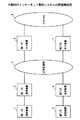
従来、インターネットを利用して電話機及び計算機で会話するインターネット電話システムは、図26及び図27に示す構成で実施されている。
図26は、計算機間で会話するインターネット電話システムを示す。
図26において、インターネット電話システムは、計算機101、計算機102、専用サーバ103、インターネット105から構成され、更に専用サーバ103は、インターネット105に接続されている全計算機のIPアドレスを一括管理する管理DB(データベース)104を有する。
【0003】
例えば、計算機101が計算機102と接続する場合、計算機101は、一旦専用サーバ103に接続し、会話を希望する計算機102のIPアドレスが管理データベース104に登録されているかどうかを確認する。尚、確認を行うときのIPアドレスの情報は、例えば、計算機102がネットワーク上で管理されている名前とする。
【0004】
管理データベース104に登録されている場合、専用サーバ103は、計算機101に対してIPアドレスを通知し、計算機101は、そのIPアドレスを利用して計算機102と接続し、インターネット105を介して通信を行う。尚、この場合、計算機101、102間で会話を行うには、各計算機のマイク等が必要となる。
【0005】
一方、図27は、計算機を利用して電話機で会話するインターネット電話システムを示す。
図27において、インターネット電話システムは、電話機111、電話機112、計算機113、計算機114、インターネット117から構成され、更に計算機113及び計算機114は、インターネット117に接続されている計算機のIPアドレスと、各計算機に接続される電話機の電話番号を管理するそれぞれ管理データベース115と管理データベース116を有する。
【0006】
例えば、電話機111が電話機112に電話をかける場合、電話機111は、最寄りの計算機113に接続を行う。計算機113は、電話機111がインターネット117を利用する資格があるかどうかの利用者認定を実行する。
利用する資格があると認定された場合、電話機111は、電話機112の電話番号をダイヤリングする。これにより、計算機113は、電話機112の最寄りの計算機114と接続し、計算機114は、電話機112と接続することにより、電話機111と電話機112がインターネット117を介して会話を行うことができる。
【0007】
【発明が解決しようとする課題】
しかしながら、従来のインターネット電話システムでは、発信者が受信者と会話する際、通常利用している電話機と比べて操作が大変であると共に、ネットワーク上で管理している計算機に自分の情報を事前に登録しておく必要があり、利用者にとっては不便な点が多い。
【0008】
本発明は、電話機の利用者が会話を希望する第三者の電話機へのダイヤリングを実行する際に、通常使用している電話機と同様に操作でき、更にインターネットを利用した低料金での会話を実現可能とするインターネット電話システムを提供する。
【0009】
【課題を解決するための手段】
そこで、上記課題を解決するため、本発明のインターネット電話システムは、請求項1に記載のように、電話機及び通信装置が公衆回線網を介して仲介装置と接続し、該仲介装置を経由してインターネット上の通信路を確立することにより、インターネットを利用した電話機及び通信装置による相互通信を実現するインターネット電話システムにおいて、該通信装置は、電話機及び通信装置からの発信により、通話相手側の通信装置及び仲介装置に公衆回線網を介してダイヤリングによる接続を行う接続手段(後述する実施例の接続部31、接続部31aに相当)と、公衆回線網及びインターネットを利用してデータの通信を行う通信手段(後述する実施例の通信部34、通信部34aに相当)と、インターネットを利用した通話中に、インターネット上の通信データを監視する監視手段(後述する実施例の監視部36、監視部36aに相当)と、該監視手段にて通信データの転送レートが保証できない状態が検出された場合、インターネットを利用した通話を公衆回線網を利用した通話に切り替える切替手段(後述する実施例の切替部37、切替部37aに相当)と、を有し、該接続手段が該通話相手側の通信装置に接続を行った後に該通信手段が該通話相手側のIPアドレスを要求し、該接続手段が該仲介装置に接続を行った後に該IPアドレスを該仲介装置に通知することにより、インターネット上の通信路を確立することを特徴とする。
【0010】
従って、本発明のインターネット電話システムによれば、利用者は、通信網としてインターネットを利用するため、遠距離についても低料金で電話を利用することができる。
また、本発明のインターネット電話システムによれば、利用者の電話操作が公衆回線網を利用しているときと同様のため、利用者は、通信網を意識する必要がない。
また、本発明のインターネット電話システムによれば、電話機の使用者は、通信網がインターネットから公衆回線網に切り替わっても、通信網を意識せずに相手との会話を継続できる。
【0016】
また、本発明の通信装置は、請求項2に記載のように、電話機と接続し、更に公衆回線網を介して仲介装置と接続することにより、インターネットを利用した相互通信を実現するインターネット電話システムの通信装置において、電話機からの発信により、通話相手側の電話機及び仲介装置に公衆回線網を介してダイヤリングによる接続を行う接続手段(後述する実施例の接続部31、接続部31aに相当)と、公衆回線網及びインターネットを利用してデータの通信を行う通信手段(後述する実施例の通信部34、通信部34aに相当)と、インターネットを利用した通話中に、インターネット上の通信データを監視する監視手段(後述する実施例の監視部36、監視部36aに相当)と、該監視手段にて通信データの転送レートが保証できない状態が検出された場合、インターネットを利用した通話を公衆回線網を利用した通話に切り替える切替手段(後述する実施例の切替部37、切替部37aに相当)と、を有し、該接続手段が該通話相手側の通信装置に接続を行った後に該通信手段が該通話相手側のIPアドレスを要求し、該接続手段が該仲介装置に接続を行った後に該IPアドレスを該仲介装置に通知することにより、インターネット上の通信路を確立することを特徴とする。
従って、本発明の通信装置によれば、利用者は、通信網としてインターネットを利用するため、遠距離についても低料金で電話を利用することができる。
また、本発明の通信装置によれば、利用者の電話操作が公衆回線網を利用しているときと同様のため、利用者は、通信網を意識する必要がない。
また、本発明の通信装置によれば、電話機の使用者は、通信網がインターネットから公衆回線網に切り替わっても、通信網を意識せずに相手との会話を継続できる。
【0022】
また、本発明の記憶媒体は、請求項3に記載のように、電話機及び通信装置が公衆回線網を介して仲介装置と接続し、仲介装置を経由してインターネット上の通信路を確立することにより、インターネットを利用した電話機及び通信装置による相互通信を実現させるためのプログラムを記憶した記憶媒体において、該通信装置を、電話機及び通信装置からの発信により、通話相手側の電話機及び仲介装置に公衆回線網を介してダイヤリングによる接続を行わせる接続手段と、公衆回線網及びインターネットを利用してデータの通信を行わせる通信手段と、インターネットを利用した通話中に、インターネット上の通信データを監視する監視手段と、該監視手段にて通信データの転送レートが保証できない状態が検出された場合、インターネットを利用した通話を公衆回線網を利用した通話に切り替える切替手段と、して動作させ、該接続手段が該通話相手側の通信装置に接続を行った後に該通信手段が該通話相手側のIPアドレスを要求し、該接続手段が該仲介装置に接続を行った後に該IPアドレスを該仲介装置に通知することにより、インターネット上の通信路を確立するプログラムを記憶したコンピュータ読み取り可能な記憶媒体とする。
従って、本発明の記憶媒体を使用すると、システムの利用者は、通信網としてインターネットを利用するため、遠距離についても低料金で電話を利用することができる。
また、本発明の記憶媒体を使用すると、利用者の電話操作が公衆回線網を利用しているときと同様のため、利用者は、通信網を意識する必要がない。
また、本発明の記憶媒体を使用すると、電話機の使用者は、通信網がインターネットから公衆回線網に切り替わっても、通信網を意識せずに相手との会話を継続できる。
【0029】
【発明の実施の形態】
以下、本発明のインターネット電話システムの実施例を図面に基づいて説明する。
図1は、本発明のインターネット電話システムの原理構成図を示す。
図1において、インターネット電話システムは、電話機としての第一の通話装置1及び第二の通話装置2と、第一の通話装置1が公衆回線網5を介して相互通信に必要な接続及び通信処理を行う計算機としての第一の通信装置3と、第二の通話装置2が公衆回線網5を介して相互通信に必要な接続及び通信処理を行う計算機としての第二の通信装置4と、公衆回線網5を各通信装置との接続媒体としインターネット8で相互通信に必要な接続及び通信処理を行うプロバイダとしての第一の仲介装置6及び第二の仲介装置7から構成される。
【0030】
例えば、第一の通話装置1の利用者から通話を希望する第三者としての第二の通話装置2に対して電話番号が入力されると、第一の通信装置3は、第二の通信装置4との間で、インターネット8で通信するための情報を公衆回線網5を介して送受信する。
相互に情報を送受信した第一の通信装置3及び第二の通信装置4は、その情報に基づいて第一の仲介装置6及び第二の仲介装置7に接続し、更に第一の仲介装置6及び第二の仲介装置7は、インターネット8を介して接続される。この状態で第一の通話装置1及び第二の通話装置2からの会話データがインターネット上を流れる。
【0031】
また、第一の通信装置3及び第二の通信装置4は、インターネット8上の転送レートが保証できなくなると、インターネット8を利用した通信を公衆回線網5を利用した通信に自動的に切り替える機能を有する。
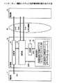
図2は、図1で説明した原理構成を利用したインターネット電話システムの実施例の構成及び動作を示す。
【0032】
図2において、本実施例のインターネット電話システムは、電話機11、電話機12、及び電話機13と、電話機11が公衆回線網16を介して相互通信に必要な接続及び通信処理を行う計算機14と、電話機12が公衆回線網16を介して相互通信に必要な接続及び通信処理を行う計算機15と、公衆回線網16を各計算機との接続媒体としインターネット19で相互通信に必要な接続及び通信処理を行うプロバイダ17及びプロバイダ18から構成される。
【0033】
上記のように構成されるインターネット電話システムにおいて、電話機11の利用者が第三者である電話機12に対してダイヤリング処理を実行した場合、電話機11が接続されている計算機14は、電話機12が接続されている計算機15との間で、公衆回線網16を介して相互の電話番号及びIPアドレスを送受信する(S1)。
【0034】
ここで、計算機14は、公衆回線網16を介して最寄りのプロバイダ17に接続し、プロバイダ17では、通信相手のIPアドレスを受信しインターネット19を介してプロバイダ18に接続する。更にプロバイダ18は、公衆回線網16を介して電話機12が接続する計算機15に接続する。この状態で、電話機11と電話機12は、通常の電話機と同様に会話を行うことができる(S2)。尚、会話終了後の通信網16及びインターネット19の開放は、各電話機の受話器を先に置いた方から実行される。
【0035】
また、図2のように構成されるインターネット電話システムにおいて、電話機11の利用者が、計算機を接続していない電話機13に対してダイヤリング処理を実行した場合、電話機11が接続している計算機14は、電話機13との間で公衆回線網16を介して相互の電話番号とIPアドレスを送受信しようとするが、電話機13に計算機が接続されていないため失敗する。
【0036】
この失敗により、計算機14は、電話機13には計算機が接続されていないことを認識し、電話機13とは公衆回線網16を介した会話ができると判断する。そのため、電話機11と電話機13の会話データは、計算機14を経由して送受信され、電話機11と電話機13は、通常の電話と同様に会話を行うことができる(S3)。尚、発信側の電話機が計算機に接続されていない場合には、通常の電話と同様に公衆回線網16を介した会話が可能となる。
【0037】
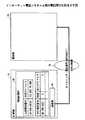
上記図2に示すようなインターネット電話システムの詳細な構成及び信号の制御を、図3から図21に従って説明する。
図3は、本発明のインターネット電話システムの詳細な構成を示す図である。図3において、インターネット電話システムは、図2と同様の構成とし、電話機11と計算機14と公衆回線網16とプロバイダ17とインターネット19から構成されている。更に計算機14は、接続部31と切断部32と変換部33と通信部34と登録部35と監視部36と切替部37と電源投入部38と情報記憶部39から構成され、公衆回線網16を介して他の計算機及びプロバイダと通信を行う。尚、後述する計算機15における詳細な構成も計算機14と同様の構成とする。またプロバイダ17は、接続部51と通信部52と切断部53と登録部54と情報蓄積部55から構成され、インターネット19を利用した会話データの送受信を可能とする。尚、後述するプロバイダ18における詳細な構成もプロバイダ17とと同様の構成とする。
【0038】
図3のように構成されるインターネット電話システムにおいて、計算機14の接続部31は、電話機11が電話番号を発信することにより、通話相手側の電話機に接続されている計算機と公衆回線網16を介して接続し、更に公衆回線網16を介してプロバイダ17に接続する機能を有する。
切断部32は、電話機11にてダイヤリングした先の電話機が接続されている計算機とのコネクションを切断し、更に公衆回線網16で接続されているプロバイダ17とのコネクションを切断する機能を有する。
【0039】
変換部33は、電話機11と相手側計算機との間の会話データのディジタル/アナログ変換を行う機能を有する。
通信部34は、相手側の電話機が接続する計算機と公衆回線網16を介して会話データ及び制御データの通信を行い、更に公衆回線網16を介してプロバイダ17と同様の通信を行う機能を有する。
【0040】
登録部35は、相手側の電話機が接続する計算機から、公衆電話網16を介して受信した情報として、例えば、電話番号及びIPアドレスを、後述する情報記憶部39に登録する機能を有する。
監視部36は、インターネット19の負荷により転送レートが保証できない状態が発生していないかどうかを監視する、即ち発信者と受信者が電話での会話に違和感を感じる転送レートであるかどうかを監視する機能を有する。
【0041】
切替部37は、インターネット19の転送レートが保証できなくなった場合、通信網をインターネット19から公衆回線網16に自動的に切り替える機能を有する。
電源投入部38は、相手側の電話機からのダイヤリング時に計算機14の電源が未投入状態の場合、計算機14の電源を自動的に投入する機能を有する。
【0042】
情報記憶部39は、相手側の電話機の制御情報として、例えば、電話番号及びIPアドレスを記憶する機能を有する。
また、図3のように構成されるインターネット電話システムにおいて、プロバイダ17の接続部51は、相手側の電話機に接続する計算機が接続されているプロバイダとインターネット19を介して接続する機能を有する。
【0043】
切断部53は、インターネット19を介して接続されている相手側のプロバイダとのコネクションを切断する機能を有する。
通信部52は、インターネット19を介して相手側の電話機が接続されるプロバイダと会話データ及び制御データの通信を行い、同様に公衆回線網16を介して計算機14と会話データ及び制御データの通信を行う機能を有する。
【0044】
登録部54は、相手側の電話機から受け取った会話データを計算機14へ通知できない場合、その会話データを後述する情報蓄積部55に登録する機能を有する。
情報蓄積部55は、計算機14へ通知できなかった会話データを保持する機能を有する。尚、保持されている会話データは後から再生することができる。
【0045】
図3のように構成されるインターネット電話システムにおいて、計算機14は、電話機11に組み込むような構成であっても良く、その場合、計算機14は必ずしも必要としない。また、公衆回線網16としては、例えば、アナログの電話回線、ディジタルの電話回線、CATV(ケーブルテレビ)、衛星回線等が有る。更にプロバイダ17は、インターネット19を利用するために必ず必要である。
【0046】
図4は、図2に示すインターネット電話システムにおいて、計算機14と計算機15間で情報を送受信する動作を示す。尚、計算機14と計算機15間での情報の送受信において、計算機14は、図3に示す各部の内、接続部31と通信部34と登録部35と情報記憶部39が動作し、計算機15は、計算機14の各部と同様の機能を有する接続部31aと通信部34aと登録部35aと情報記憶部39aが動作する。
【0047】
電話機11の利用者が計算機15に接続する相手の電話番号をダイヤリングすると(S11)、計算機14の接続部31は、情報記憶部39に相手の電話番号及びIPアドレスが登録されているかどうかを検索する(S12)。
電話番号及びIPアドレスが登録されている場合、計算機14と計算機15間で情報の送受信は行われない。
【0048】
一方、電話番号及びIPアドレスが登録されていない場合、計算機14の接続部31は、公衆回線網16を介して計算機15の接続部31aにダイヤリングを行い(S13)、ダイヤリングが成功すると通常の電話機と同様に通信が可能となる。次に計算機14の通信部34は、計算機15の通信部34aに対して、IPアドレス要求を行う(S14)。この時、同時に通信部34は、情報記憶部39が管理している電話機11の電話番号及びIPアドレスを通知する。
【0049】
通信部34aは、通知された電話番号及びIPアドレスを受信し、更に登録部35aは、その電話番号及びIPアドレスを情報記憶部39aに登録する(S15)。
ここで、通信部34aは、情報記憶部39aに登録されている電話機12の電話番号とIPアドレスを読み出し(S16)、通信部34に通知する(S17)。通信部34が電話機12の電話番号及びIPアドレスを受信すると、登録部35は、その電話番号及びIPアドレスを情報記憶部39に登録する(S18)。情報記憶部39、及び情報記憶部39aに登録されている情報は、インターネット19を利用して会話するときに必要となる情報として管理及び利用される。
【0050】
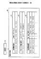
図5は、本発明の情報記憶部39及び情報記憶部39aが管理する情報の一例を示す。
図5において、例えば、情報記憶部39に管理される情報は、電話機11のネットワーク情報61とプロバイダ情報62と相手側のネットワーク情報63から構成され、登録部35によって登録される。尚、情報記憶部39aに管理される情報は、電話機12のネットワーク情報とプロバイダ情報と相手側のネットワーク情報から構成され、登録部35aによって登録される。
【0051】
電話機11のネットワーク情報61では、電話機11の電話番号とIPアドレスが管理されている。
プロバイダ情報62では、プロバイダの電話番号と利用者IDと利用者認証用のパスワードが管理されている。
相手側のネットワーク情報63では、相手側の電話番号とIPアドレスの他、登録されている相手と通常の公衆回線接続をするか、インターネット接続をするかを制御する、例えば、’1’、’0’の情報を管理する。
【0052】
図6は、計算機14と計算機15との間で公衆回線網16にて送受信される情報の一例を示す。
計算機14の通信部34は、通信部34aに対してIPアドレス要求を行い、この時、同時に情報記憶部39に登録されているネットワーク情報61から電話機11の電話番号’012345678’とIPアドレス’12345678900’を読み出し、その情報を通知する。
【0053】
前記情報を受信した通信部34aは、その情報を相手側のネットワーク情報63aとして登録し、更に情報記憶部39aに登録されているネットワーク情報61aから電話機12の電話番号’987654321’とIPアドレス’98765432100’を読み出し、その情報を通信部34に対して通知する。通信部34aからの電話番号とIPアドレスを受信した通信部34は、その情報を情報記憶装置39に登録する。
【0054】
図7は、図2に示すインターネット電話システムにおいて、計算機14と計算機15がIP型でインターネット接続されている場合の制御を示す。
この場合、計算機14と計算機15は、それぞれが固有のIPアドレスを有し、更にそれぞれの情報記憶部39と情報記憶部39aがお互いのIPアドレスを管理している。この状態で計算機14と計算機15とは、プロバイダ17及びプロバイダ18を経由してIP型でインターネット19にて接続され、この通信パス上に各種制御データを流す。
【0055】
図8は、図2に示すインターネット電話システムにおいて、計算機14がIP型でインターネット接続され、計算機15がダイヤルアップ側でインターネット接続されている場合の参考図を示す。
【0056】
図9は、図2に示すインターネット電話システムにおいて、発信側の計算機14とプロバイダ17間で公衆回線網16にて情報を送受信する動作を示す。尚、計算機14とプロバイダ17間での情報の送受信において、計算機14は、図3に示す各部の内、接続部31と通信部34と情報記憶部39が動作し、プロバイダ17は、接続部51と通信部52と情報蓄積部55が動作する。
【0057】
計算機14の接続部31は、情報記憶部39に登録されているプロバイダの電話番号として、例えば、’11ー111ー1111’を読み出し(S21)、プロバイダ17の接続部51にダイヤリングする(S22)。
ここで、プロバイダ17の通信部52は、通信部34に対して利用者(計算機14)の認証を行うため計算機14のユーザIDとパスワードを督促する(S23)。ユーザIDとパスワードの督促に対して、計算機14の通信部34は、情報記憶部39に登録されているユーザIDとして、例えば、’U01’を、パスワードとして、例えば、’PSW01’を、更に通話を希望する相手の電話番号として、例えば、’98ー765ー4321’を、相手のIPアドレスとして、例えば、’987.654.32.100’を読み出し(S24)、プロバイダ17の通信部52に対して通知する(S25)。尚、同時に通信部34は、通信部52に対して計算機14の電話番号とIPアドレスも通知する。
【0058】
この状態で通信部52は、情報蓄積部55に登録されているユーザIDとパスワードを確認し(S26)、一致した場合、インターネット接続を許可し、一致しなかった場合、利用者(計算機14)からの要求を拒否する。
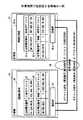
図10は、プロバイダ17が登録されているユーザIDとパスワードを確認するときに必要となる情報蓄積部55が管理する情報の一例を示す。
【0059】
管理する情報は、プロバイダ接続情報71と留守録情報72から構成され、図3に示すプロバイダ17の登録部54によって情報が登録される。
情報蓄積部55に登録されているプロバイダ接続情報71は、利用者の認証を行うためのユーザ電話番号として、例えば、’01ー234ー5678’が、ユーザIDとして、例えば、’U01’が、パスワードとして、例えば、’PSW01’が管理されている。
【0060】
留守録情報71は、例えば、ユーザ電話番号’01ー234ー5678’に対応付けられた音声データとして’U01.WAV’が管理されている。
図11は、図2に示すインターネット電話システムにおいて、発信側のプロバイダ17と受信側のプロバイダ18間で情報を送受信する動作を示す。尚、プロバイダ17とプロバイダ18間でインターネット19での情報の送受信において、プロバイダ17は、接続部51と通信部52が動作し、プロバイダ18は、プロバイダ17の各部と同様の機能を有する接続部51aと通信部52aと情報蓄積部55aが動作する。
【0061】
発信側のプロバイダ17の接続部51は、図2に示す発信側の計算機14からの受信側のIPアドレスに基づいて、受信側のプロバイダ18の接続部51aとIP−IP接続を行う(S31)。
ここで、通信部52は、発信側の計算機14の電話番号、IPアドレスと、更に受信側の電話番号、IPアドレスをプロバイダ18の通信部52aに対して通知する(S32)。
【0062】
通信部52からの通知を受信した通信部52aは、その情報が情報蓄積部55aに登録されている電話番号かどうかを確認し(S33)、電話番号が登録されている場合は、接続部51aが受信側の計算機15との接続処理を実行し、電話番号が登録されていない場合は、プロバイダ17からの要求を拒否することが可能となる。尚、ステップ33の確認処理は、必須である必要はない。
【0063】
図12は、図2に示すインターネット電話システムにおいて、受信側のプロバイダ18と受信側の計算機15間で公衆回線網16にて情報を送受信する動作を示す。尚、プロバイダ18と計算機15間での情報の送受信において、プロバイダ18は、接続部51aと通信部52aと情報蓄積部55aが動作し、計算機15は、接続部31aと通信部34aと情報記憶部39aが動作する。
【0064】
受信側のプロバイダ18は、発信側のプロバイダ17からの受信側の電話番号に基づいて、計算機15の接続部31aにダイヤリングを行う(S41)。
計算機15の通信部34aは、情報記憶部39aに登録されている受信側のユーザIDとして、例えば、’U02’を、パスワードとして、例えば、’PSW02’を読み出し(S42)、プロバイダ18の通信部52aに通知する(S43)。
【0065】
通信部34aからの通知を受信した通信部52aは、情報蓄積部55aに登録されているユーザID及びパスワードを確認し(S44)、一致する場合は、インターネット接続を許可し、一致しない場合は、発信者側からの要求を拒否する。 プロバイダ18に認証されると、通信部52aから発信者の電話番号及びIPアドレスが通信部34aに通知されるため、通信部34aでは、情報記憶部39aに登録されている登録情報と異なる場合、その情報を更新する。
【0066】
この状態で計算機15は、電話機12を呼び出し(S45)、受信側の利用者は、電話機12の受話器を取ることによりインターネットを利用した会話を開始する。
図13は、図2に示すインターネット電話システムにおいて、インターネット19を利用した通話で転送レートが確保できなくなった場合に、通常の公衆回線網16での通話に回線を自動切替する動作を示す。尚、インターネット19から公衆回線網16への自動切替において、例えば、発信側の計算機14は、通信部34と監視部36と切替部37が動作し、発信側のプロバイダ17は、通信部52が動作し、更に受信側の計算機15は、計算機14の各部と同様の機能を有する通信部34aと監視部36aと切替部37aが動作し、受信側のプロバイダ18は、プロバイダ17の通信部52と同様の機能を有する通信部52aが動作する。
【0067】
電話機11と電話機12間でのインターネット19を利用した通話において、本実施例のインターネット電話システムは、計算機14の通信部34、プロバイダ17の通信部52、プロバイダ18の通信部52a、計算機15の通信部34aを介して通話が行われている(S51)。
この状態で、インターネット19の転送レートが保証できなくなり、通話中の音声が聞きづらくなった場合、本実施例のインターネット電話システムは、通信部34及び通信部34aにより、通話に使用する回線をインターネット19から公衆回線網16に自動的に切替えて通話を継続する(S52)。
【0068】
上記ステップ52による回線の切り替えは、通信部34が通信するデータの転送レートを監視部36が監視し、予め特定の値に設定された転送レートを保証できなくなった場合、切替部37が通信部34に対して、インターネット19から公衆回線網16に回線を切り替える旨の制御データを通知し、通信網34が回線を切り替える。同様にステップ52による回線の切り替えは、計算機15でも行われ、通信部34aが通信するデータの転送レートを監視部36aが監視し、予め特定の値に設定された転送レートを保証できなくなった場合、切替部37aが通信部34aに対して、インターネット19から公衆回線網16に回線を切り替える旨の制御データを通知し、通信網34aが回線を切り替える。このように本実施例のインターネット電話システムによる回線の切り替えは、転送レートを保証できないと認識した計算機の方から行う。
【0069】
図14は、図2に示すインターネット電話システムにおいて、計算機14に接続されている電話機11と計算機に接続されていない既存の電話機13間での動作を示す。尚、計算機14に接続されている電話機11と計算機に接続されていない既存の電話機13間での動作において、計算機14は、接続部31と通信部34と登録部35と情報記憶部39が動作する。
【0070】
電話機11から電話機13に対してダイヤリングを実行すると(S61)、計算機14の接続部31は、電話機11からの電話番号に基づいて電話機13にダイヤリングを実行する(S62)。
ここで、計算機14の通信部34は、情報記憶部39に登録されている相手電話番号情報を読み出し(S63)、相手電話番号情報の中に電話機13の電話番号情報が存在しない場合、または、相手電話番号情報の制御情報が’1’の場合、電話機13に対してIPアドレス要求を行う(S64)。尚、相手電話番号情報の制御情報は、’1’の場合、インターネットを利用した通話を実施する旨を、’0’の場合、インターネットを利用した通話を実施しない旨を表す。
【0071】
図14の場合、電話機13は、IPアドレス要求を認識できないため、IPアドレスが得られない。また、通信部34による確認で、情報記憶部39に相手電話番号情報が登録されていなかった場合は、登録部35は、電話機13の電話番号を相手電話番号情報に登録する(S65)。
この状態で通信部34は、IPアドレス要求が失敗したことにより、電話機13が計算機と接続されていない通常の電話機と認識し、電話機11からの会話データを通常の電話と同様に公衆回線網16を介して電話機13へ通知する(S66)。
【0072】
図15は、図2に示すインターネット電話システムにおいて、計算機14に接続されている電話機11と計算機に接続されていない既存の電話機13間での図14に対応する制御を示す。
電話機11が接続されている計算機14は、相手の電話機13に計算機が接続されているかどうかを認識できていないため、情報記憶部39が管理する相手電話番号を参照する。
【0073】
このとき、相手電話番号情報が登録されていない場合、または、相手電話番号情報が登録され、且つ制御情報が’1’の場合、計算機14は、相手(電話機13)が計算機であると想定して公衆回線網16を利用して、電話機13に対して図15のようにIPアドレス要求を行う。計算機14は、同時に電話機11の電話番号及びIPアドレスを電話機13に対して通知する。
【0074】
ところが電話機13では、IPアドレス要求、電話機11の電話番号、及びIPアドレスを認識できない。このような状態は、通信部34では、回線の切断及びタイムアウトが発生したNG状態と認識する。この場合、計算機11の通信部34は、電話機13に対して再度ダイヤリングを実行し、公衆回線網16による通話を実行する。
【0075】
図16は、図2に示すインターネット電話システムにおいて、計算機14に接続されている電話機11と計算機に接続されていない既存の電話機13間での、図14とは別の動作を示す。尚、計算機14に接続されている電話機11と計算機に接続されていない既存の電話機13間での動作において、計算機14は、接続部31と通信部34と情報記憶部39が動作する。また、図14の動作との違いは、情報記憶部39に登録されている相手電話番号情報の制御情報が予め’0’に設定され、インターネットを利用しない旨が登録されている点である。
【0076】
電話機11から電話機13に対してダイヤリングを実行すると(S71)、計算機14の接続部31は、電話機11からの電話番号に基づいて電話機13にダイヤリングを実行する(S72)。
ここで、計算機14の通信部34は、情報記憶部39に登録されている相手電話番号情報を読み出し(S73)、相手電話番号情報の制御情報が’0’の場合、電話機13に対してIPアドレス要求を実行せずに、電話機11からの会話データを通常の電話と同様に公衆回線網16を介して電話機13へ通知する(S74)。
【0077】
図17は、図2に示すインターネット電話システムにおいて、計算機14に接続されている電話機11と計算機に接続されていない既存の電話機13間での、図16に対応する制御を示す。
電話機11が接続されている計算機14は、相手の電話機13に計算機が接続されているかどうかを認識できていないため、情報記憶部39が管理する相手電話番号を参照する。
【0078】
このとき、相手電話番号情報が登録され、且つ制御情報が’0’の場合、計算機14は、相手(電話機13)が計算機が接続されていない電話機であると認識し、公衆回線網16を利用してダイヤリングを実行し、公衆回線網16による通話を実行する。
図18は、図2に示すインターネット電話システムによる留守録の動作を示す。尚、留守録の動作において、例えば、発信側のプロバイダ17は、接続部51と通信部52が動作し、受信側のプロバイダ18は、プロバイダ17の各部と同様の機能を有する接続部51aと通信部52aと登録部54aと情報蓄積部55aが動作する。
【0079】
発信側の計算機14からプロバイダ17にダイヤリングを実行し、PPP接続を実施する(S81)。次にプロバイダ17の接続部51とプロバイダ18の接続部51a間でIP−IP接続を実施する(S82)。
ここでプロバイダ18の接続部51aは、受信側の計算機15に対して接続を試みる(S83)が、例えば、計算機15の電源が未投入等のため接続が失敗した場合、プロバイダ17の通信部52からプロバイダ18の通信部52aに通知された会話データ(S84)は、登録部54aが情報蓄積部55aに登録し(S85)、情報蓄積部55aが利用者毎の会話データとして管理する。また、情報蓄積部55aに登録された会話データは、計算機15から問い合わせることにより聞くことができる。
【0080】
図19は、図2に示すインターネット電話システムによるディジタル/アナログ変換の動作を示す。尚、ディジタル/アナログ変換の動作において、計算機14は、変換部33と通信部34が動作する。また、図2における計算機15も同様の機能を有する。
計算機14の変換部33は、回線上のデータがアナログデータであれば(S91)、該アナログデータに対してディジタル/アナログ変換を行い、ディジタルデータに変換する(S93)。一方、回線上のデータがディジタルデータであれば(S92)、該ディジタルデータは変換部33を経由して、そのまま出力される(S93)。
【0081】
ここで通信部34は、該ディジタルデータを解析し、例えば、図19のようにヘッダが’01’であれば、会話データとして相手の電話機に送信する必要があるので、変換部33にそのディジタルデータを送信する(S94)。一方、ディジタルデータが、例えば、図19のようにヘッダ’00’であれば、即ち、通信網切り替え要求、IPアドレス要求、IPアドレス通知等であれば、制御データとして通信部34にて制御を実行する。
【0082】
ステップ94の処理でディジタルデータ(会話データ)を受信した変換部33は、受信側の電話機がアナログの電話機13aの場合、その会話データをアナログデータに変換し、電話機に通知する(S95)。一方、ステップ94の処理でディジタルデータ(会話データ)を受信した変換部33は、受信側の電話機がディジタルの電話機13bの場合、その会話データを変換せずに電話機に通知する(S96)。尚、アナログの電話機13a及びディジタルの電話機13bからのデータも同様に変換して相手の電話機に送信される。
【0083】
図20は、図2に示すインターネット電話システムにおいて、相手側の計算機15の主電源は投入されているが、必要なハード及びソフトが起動されていない状態の場合の、計算機14と計算機15が情報を送受信する動作を示す。尚、計算機14と計算機15間での情報の送受信において、計算機14は、接続部31と通信部34と情報記憶部39が動作し、計算機15は、計算機14の各部と同様の機能を有する接続部31aと通信部34aと情報記憶部39aと電源投入部38aが動作する。また、図2における計算機14にも同様の機能を有する電源投入部38が存在する。
【0084】
計算機14と計算機15間で情報の送受信が行われる際、計算機15の電源は投入されているが必要なソフト及びハードが起動されていない場合、例えば、電話機11が電話番号をダイヤリングすると(S101)、計算機14の接続部31は、公衆回線網16を介して相手の計算機15の接続部31aに対してその電話番号をダイヤリングする(S102)。接続部31aは、電源投入部38aを起動し(S103)、電源投入部38aは、必要なハード及びソフトを起動する処理を実行する。
【0085】
図20では、電源投入部38aは、通信部34aを起動している。計算機14の通信部34は、情報記憶部39の管理する情報を参照し(S104)、計算機15の通信部34aに対してIPアドレス要求を通知する(S105)。
IPアドレス要求を通知された通信部34aは、情報記憶部39aが管理する情報を参照し(S106)、計算機14の通信部34にIPアドレス通知を送信する(S107)。尚、図20の動作の場合、各計算機は、ダイヤリング処理による情報を受信できることが必須となる。また、ダイヤリングが失敗するような場合は、図18による留守録の動作を実行する。
【0086】
図21は、図2に示すインターネット電話システムにおいて、受信側のプロバイダ18と受信側の計算機15間で情報を送受信する動作を示す、図12とは別の動作例を示す。尚、プロバイダ18と計算機15間での情報の送受信において、プロバイダ18は、接続部51aと通信部52aと情報蓄積部55aが動作し、計算機15は、接続部31aと通信部34aと情報記憶部39aと電源投入部38aが動作する。また、図2における計算機14にも同様の機能を有する電源投入部38が存在する。
【0087】
計算機14と計算機15間でインターネット接続する際、計算機15の電源は投入されているが必要なソフト及びハードが起動されていない場合、且つ発信側の計算機14に既に受信側の情報が登録されている場合の情報の送受信を説明する。
この状態で発信側のプロバイダ17と受信側のプロバイダ18間のIP−IP接続が完了すると、プロバイダ18の接続部51aは、公衆回線網16を利用して受信側の計算機15にダイヤリングを実行する(S111)。
【0088】
計算機15の接続部31aは、電源投入部38aを起動し(S112)、必要なハード及びソフトを起動する。図21では、通信部34aを起動している。
この状態で、通信部52aは、計算機15の通信部34aに対して利用者を認証するためのユーザIDとパスワードを督促し(S113)、通知を受信した通信部34aは、情報記憶部39aが管理する情報を参照し(S114)、更にプロバイダ18の通信部52aに対して、ユーザIDとパスワードを通知する(S115)。
【0089】
通信部34aからの通知を受信した通信部52aは、情報蓄積部55aに登録されているユーザID及びパスワードを確認し(S116)、一致する場合は、インターネット接続を許可し、一致しない場合は、発信者側からの要求を拒否する。
プロバイダ18に認証されると、通信部52aから発信者の電話番号及びIPアドレスが通信部34aに通知されるため、通信部34aでは、情報記憶部39aに登録されている登録情報と異なる場合、その情報を更新する。
【0090】
この状態で計算機15は、電話機12を呼び出し(S117)、受信側の利用者は、電話機12の受話器を取ることによりインターネットを利用した会話を開始する。
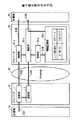
図22は、図2に示すようなインターネット電話システムにおいて、IP−IP接続によりインターネット19を利用するIP型インターネット電話システムの処理のフローチャートを示す。
【0091】
発信側の電話機11が受信側の電話機12に対して電話番号をダイヤリングすると(S201)、電話番号を受信した発信側の計算機14は、計算機14中に受信側の電話機12の電話番号が登録されているかどうかを検索する。
登録されていない場合、計算機14は、受信側の計算機15に対して公衆回線網16を利用して、発信側の電話機11がダイヤルした電話番号をダイヤリングし、IPアドレス要求を行う(S202)。また、同時に発信側の電話番号とIPアドレスも通知する。受信側の計算機15がIPアドレス要求を受信すると、計算機15は、発信側の電話番号とIPアドレスを記憶し、公衆回線網16を介してIPアドレスを発信側の計算機14に通知する(S203)。発信側の計算機14は、受信したIPアドレスと電話番号を記憶し、受信側の計算機15と接続されている公衆回線網16を切断し、更にプロバイダ17及びプロバイダ18を介して受信側の計算機15のIPアドレスとインターネット19上でIP−IP接続を行う(S204)。
【0092】
一方、ステップ201のダイヤリングにおいて、計算機14中に受信側の電話機12の電話番号が登録されている場合、発信側の計算機14は、プロバイダ17及びプロバイダ18を介して、受信側の計算機15のIPアドレスとインターネット19上でIP−IP接続を行う(S204)。
IP−IP接続が完了すると、受信側の計算機15は、受信側の電話機12の呼び出しを実行し(S205)、この状態で電話機11と電話機12は、通話を開始できる(S206)。
【0093】
通話中、発信側の計算機14及び受信側の計算機15は、インターネット19上の会話データの転送レートに異常がないかどうかを常に監視する。尚、会話データの転送レートは、予め、システムの利用者により設定されているものとする。また、この状態で電話機11及び電話機12の利用者がオンフックを実行すると(S207、S208)、IP−IP接続は切断され、通話が終了する(S209)。
【0094】
例えば、通話中に発信側の計算機14で転送レートの異常が検出された場合、発信側の計算機14は、受信側の計算機15に対して網切替通知を送信し(S210)、インターネット19上の計算機間のIP−IP接続を切断する(S211)。尚、通話中に受信側の計算機15で転送レートの異常が検出された場合も同様に、受信側の計算機15は、発信側の計算機14に対して網切替通知を送信し(S210)、インターネット19上の計算機間のIP−IP接続を切断する(S211)。
【0095】
IP−IP接続を切断後、発信側の計算機14は、受信側の計算機15に対して公衆回線網16を介してダイヤリングを実行し(S212)、公衆回線網16でのコネクションを確立する(S213)。そのため、電話機11及び電話機12の利用者は、インターネット19から公衆回線網16への切り替えを意識することなく通話を行うことができる。
【0096】
また、この状態で電話機11及び電話機12の利用者がオンフックを実行すると(S214、S215)、インターネット19を介してIP−IP接続されている場合は、IP−IP接続は切断され(S216)、公衆回線網16を介してコネクションが接続されている場合は、そのコネクションが切断され、通話が終了する。
【0113】
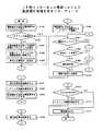
図23は、図2に示すようなインターネット電話システムにおいて、IP−IP接続によりインターネット19を利用するIP型インターネット電話システムの発信側の処理のフローチャートを示す。
発信側の電話機11が受信側の電話機12に対して電話番号をダイヤリングすると(S301)、電話番号を受信した発信側の計算機14は、計算機14中に受信側の電話番号とIPアドレスが登録されているかどうかを検索する(S302)。
【0114】
登録されていない場合(S302、NO)、発信側の計算機14は、受信側の計算機15に対して公衆回線網16を利用して、発信側の電話機11がダイヤルした電話番号をダイヤリングし、IPアドレス要求を行う(S303)。また、同時に発信側の電話番号とIPアドレスも通知する。
IPアドレス要求に対する応答として、計算機15からのIPアドレス及び電話番号が公衆回線網16を介して発信側の計算機14に通知されると、発信側の計算機14は、受信したIPアドレスと電話番号を記憶し(S304)、受信側の計算機15と接続されている公衆回線網16を切断し(S305)、更にプロバイダ17及びプロバイダ18を介して受信側の計算機15のIPアドレスとインターネット19上でIP−IP接続を行う(S306)。
【0115】
一方、ステップ302の検索において、計算機14中に受信側の電話機12の電話番号及びIPアドレスが登録されている場合(S302、YES)、発信側の計算機14は、プロバイダ17及びプロバイダ18を介して、受信側の計算機15のIPアドレスとインターネット19上でIP−IP接続を行う(S306)。
【0116】
IP−IP接続が完了すると、受信側の計算機15は、受信側の電話機12の呼び出しを実行し、この状態で電話機11と電話機12は通話を開始できる。
通話中、電話機11の利用者がオンフックを実行すると(S307、YES)、発信側の計算機14は、インターネット19による通話中の場合(S315、YES)、IP−IP接続を切断し(S316)、公衆回線網16による通話中の場合(S315、NO)、公衆回線網16のコネクションを切断し(S317)、それぞれ通話を終了する。
【0117】
また、発信側の計算機14は、インターネット19上の会話データの転送レートに異常がないかどうかを常に監視する(S308)。尚、会話データの転送レートは、予め、システムの利用者により設定されているものとする。
例えば、通話中に発信側の計算機14で転送レートの異常が検出された場合(S307、NO)(S308、YES)、発信側の電話機14は、受信側の計算機15に対して網切替通知を送信し(S311)、インターネット19上の計算機間のIP−IP接続を切断する(S312)。
【0118】
IP−IP接続を切断後、発信側の計算機14は、受信側の計算機15に対して公衆回線網16を介してダイヤリングを実行し(S313)、公衆回線網16でのコネクションを確立する。そのため、電話機11の利用者は、インターネット19から公衆回線網16への切り替えを意識することなく通話を行うことができる。
【0119】
また、例えば、通話中に受信側の計算機15で転送レートの異常が検出され、計算機14が計算機15からの網切替通知を受信すると(S307、NO)(S308、NO)(S309、YES)、発信側の電話機14は、網切替状態を記憶する(S314)。
また、通話中に電話機11の利用者がオンフックを実行していない場合(S307、NO)、通話中に発信側の計算機14で転送レートの異常が検出されていない場合(S308、NO)、且つ通話中に計算機15からの網切替通知を受信していない場合(S309、NO)、発信側の計算機14は通話状態を継続する(S310)。
【0120】
図24は、図2に示すようなインターネット電話システムにおいて、IP−IP接続によりインターネット19を利用するIP型インターネット電話システムの受信側の処理のフローチャートを示す。
受信側の計算機15が発信側の電話機11からのダイヤリングを受信すると(S321)、受信側の計算機15は、IPアドレス要求、発信側の電話番号及びIPアドレスを受信する(S322)。更にIPアドレス要求を受信した受信側の計算機15は、応答として発信側の計算機14に対して、受信側の電話番号及びIPアドレスを通知する(S323)。
【0121】
発信側からの電話番号及びIPアドレスを受信した受信側の計算機15は、その情報が計算機15内に登録されているかどうかを検索する(S324)。
登録されていない場合(S324、NO)、受信側の計算機15は、発信側からの電話番号及びIPアドレスを登録し(S325)、発信側の計算機14と接続されている公衆回線網16を切断し(S326)、更に発信側の計算機14とのインターネット19上のIP−IP接続を待つ(S327)。
【0122】
一方、ステップ324の検索において、計算機15中に発信側の電話番号及びIPアドレスが登録されている場合(S324、YES)、受信側の計算機15は、発信側の計算機14とのインターネット19上のIP−IP接続を待つ(S327)。
IP−IP接続が完了すると、受信側の計算機15は、受信側の電話機12の呼び出しを実行し、この状態で電話機11と電話機12は通話を開始できる。
【0123】
通話中、電話機12の利用者がオンフックを実行すると(S328、YES)、受信側の計算機15は、インターネット19による通話中の場合(S336、YES)、IP−IP接続を切断し(S337)、公衆回線網16による通話中の場合(S336、NO)、公衆回線網16のコネクションを切断し(S338)、それぞれ通話を終了する。
【0124】
また、受信側の計算機15は、インターネット19上の会話データの転送レートに異常がないかどうかを常に監視する(S329)。尚、会話データの転送レートは、予め、システムの利用者により設定されているものとする。
例えば、通話中に発信側の計算機14で転送レートの異常が検出された場合(S328、NO)(S329、YES)、受信側の電話機15は、発信側の計算機14に対して網切替通知を送信し(S332)、インターネット19上の計算機間のIP−IP接続を切断する(S333)。
【0125】
IP−IP接続を切断後、受信側の計算機15は、発信側の計算機14からのダイヤリングを待ち(S334)、発信側の計算機14からのダイヤリングがあると、公衆回線網16でのコネクションを確立する。そのため、電話機12の利用者は、インターネット19から公衆回線網16への切り替えを意識することなく通話を行うことができる。
【0126】
また、例えば、通話中に発信側の計算機14で転送レートの異常が検出され、計算機15が計算機14からの網切替通知を受信すると(S328、NO)(S329、NO)(S330、YES)、受信側の電話機15は、網切替状態を記憶する(S335)。
また、通話中に電話機12の利用者がオンフックを実行していない場合(S328、NO)、通話中に受信側の計算機15で転送レートの異常が検出されていない場合(S329、NO)、且つ通話中に計算機14からの網切替通知を受信していない場合(S330、NO)、受信側の計算機15は通話状態を継続する(S331)。
【0153】
上記、本実施例のインターネット電話システムは、発信側の電話機が受信側の電話機と通話を実行する際、通常利用している電話機と操作が同様であり、ネットワーク上で管理している計算機に自分の情報を事前に登録しておく必要がなく、利用者にとっては大変便利な点が多い。
また、本実施例のインターネット電話システムは、利用者が通信網としてインターネットを利用するため、遠距離についても低料金で電話を利用することができる。
【0154】
また、本実施例のインターネット電話システムは、利用者の電話操作が公衆回線網を利用しているときと同様のため、利用者は、通信網を意識する必要がない。
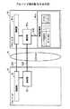
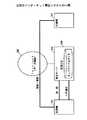
図25は、インターネットを利用した通話を行うインターネット電話システムの通信装置としての計算機の構成図を示す。
【0155】
図25において、計算機は、CPUを含む制御ユニット301とメモリユニット302と表示ユニット303と入力ユニット304とCD−ROMドライブユニット305とディスクユニット306とを有している。これらの各ユニットは、システムバスAを介して接続されている。
制御ユニット301は、インターネット電話システムの処理を格納したプログラムを実行する。
【0156】
メモリユニット302は、RAM、ROM等のメモリを含み、制御ユニット101が実行すべきプログラム、処理の過程で得られた必要なデータ等を記憶する。
表示ユニット303は、CRTやLCD(液晶表示パネル)等で構成され、各種画面を表示する。
【0157】
入力ユニット304は、キーボード、マウス等で構成される。
CD−ROM400には、インターネット電話システムの処理を実行するプログラムが格納されている。
CD−ROMドライブユニット305にセットされたCD−ROM400からプログラムがディスクユニット306にインストールされる。そして、計算機を立ち上げるときにディスクユニット306から読み出されたプログラムがメモリユニット302に格納される。この状態で、制御ユニット301(CPU)は、メモリユニット302に格納されたプログラムに従って、インターネット電話システムに関する処理を実行する。
【0158】
尚、CD−ROM400にてインターネット電話システム関する処理を記述したプログラムを提供しているが、このプログラムの記憶媒体は、これに限定されることなく、システムを構成するコンピュータに応じて、フロッピーディスク等の磁気ディスク、光磁気ディスク、磁気テープ等の他の記憶媒体を用いることも可能である。
【0159】
【発明の効果】
上述の如く、本発明のインターネット電話システムによれば、発信者が受信者と会話する際、通常利用している電話機と操作が同様であり、ネットワーク上で管理している計算機に自分の情報を事前に登録しておく必要がなく、利用者にとっては大変便利な点が多い。
【0160】
また、本発明のインターネット電話システムによれば、利用者は、通信網としてインターネットを利用するため、遠距離についても低料金で電話を利用することができる。
また、本発明のインターネット電話システムによれば、利用者の電話操作が公衆回線網を利用しているときと同様のため、利用者は、通信網を意識する必要がない。
【0161】
従って、本発明は、電話機の利用者が会話を希望する第三者の電話機へのダイヤリングを実行する際に、通常使用している電話機と同様に操作でき、更にインターネットを利用した低料金での会話を実現可能とするインターネット電話システムを提供することができる。
【図面の簡単な説明】
【図1】 本発明のインターネット電話システムの原理構成図である。
【図2】 インターネット電話システムの実施形態構成及び動作説明を示す図である。
【図3】 インターネット電話システムの構成例である。
【図4】 計算機間での情報送受信の動作を示す図である。
【図5】 情報記憶部が管理する情報の一例である。
【図6】 計算機間で送受信する情報の一例である。
【図7】 計算機間の制御を示す図である。
【図8】参考図である。
【図9】 発信側の計算機とプロバイダ間の動作を示す図である。
【図10】 情報蓄積部が管理する情報の一例である。
【図11】 プロバイダ間の動作を示す図である。
【図12】 受信側のプロバイダと計算機間の動作を示す図である。
【図13】 インターネットと公衆回線網の自動切替の動作を示す図である。
【図14】 インターネット電話システムと既存電話間の動作を示す図である。
【図15】 インターネット電話システムと既存電話間の制御を示す図である。
【図16】 インターネット電話システムと既存電話間の動作を示す図である。
【図17】 インターネット電話システムと既存電話間の制御を示す図である。
【図18】 留守録の動作を示す図である。
【図19】 アナログ/ディジタル変換の動作を示す図である。
【図20】 計算機間の動作を示す図である。
【図21】 受信側のプロバイダと計算機間の動作を示す図である。
【図22】 IP型インターネット電話システムの処理を示すフローチャートである。
【図23】IP型インターネット電話システムで発信側の処理を示すフローチャートである。
【図24】IP型インターネット電話システムで受信側の処理を示すフローチャートである。
【図25】通信装置の構成図である。
【図26】従来のインターネット電話システムの一例である。
【図27】従来のインターネット電話システムの一例である。
【符号の説明】
1 第一の通話装置
2 第二の通話装置
3 第一の通信装置
4 第二の通信装置
5 公衆回線網
6 第一の仲介装置
7 第二の仲介装置
8 インターネット
11 電話機
12 電話機
13 電話機
14 計算機
15 計算機
16 公衆回線網
17 プロバイダ
18 プロバイダ
19 インターネット
31 接続部
32 切断部
33 変換部
34 通信部
35 登録部
36 監視部
37 切替部
38 電源投入部
39 情報記憶部
51 接続部
52 通信部
53 切断部
54 登録部
55 情報蓄積部
61 自側のネットワーク情報
62 プロバイダ情報
63 相手側のネットワーク情報
71 プロバイダ接続情報
72 留守録情報
101 計算機
102 計算機
103 専用サーバ
104 管理データベース
105 インターネット
111 電話機
112 電話機
113 計算機
114 計算機
115 管理データベース
116 管理データベース
117 インターネット
301 制御ユニット
302 メモリユニット
303 表示ユニット
304 入力ユニット
305 CDROMドライブユニット
306 ディスクユニット
400 CDROM[0001]
BACKGROUND OF THE INVENTION
The present invention relates to the Internet, and relates to an Internet telephone system that uses the Internet to communicate with a telephone and a computer.
[0002]
[Prior art]
Conventionally, an Internet telephone system for talking on a telephone and a computer using the Internet has been26 and 27It has been implemented in the configuration shown in.
FIG.Shows an Internet telephone system for conversation between computers.
FIG.The Internet telephone system is composed of a
[0003]
For example, when the
[0004]
When registered in the
[0005]
on the other hand,FIG.Shows an Internet telephone system in which a computer is used to converse on a telephone.
FIG.The Internet telephone system includes a
[0006]
For example, when the
If the
[0007]
[Problems to be solved by the invention]
However, in the conventional Internet telephone system, when the caller has a conversation with the receiver, the operation is difficult compared to the telephone normally used, and his / her information is preliminarily stored in a computer managed on the network. It is necessary to register, and there are many inconveniences for users.
[0008]
The present invention can be operated in the same way as a normally used telephone when dialing a third party's telephone that the telephone user wants to converse with, and further, a low-cost conversation using the Internet. An Internet telephone system that can realize the above is provided.
[0009]
[Means for Solving the Problems]
Therefore, in order to solve the above problems, the Internet telephone system of the present invention is such that, as described in
[0010]
Therefore, according to the Internet telephone system of the present invention, since the user uses the Internet as a communication network, the user can use the telephone even at a long distance at a low charge.
Further, according to the Internet telephone system of the present invention, the user does not need to be aware of the communication network because the telephone operation of the user is the same as when using the public line network.
According to the Internet telephone system of the present invention, the telephone user can continue the conversation with the other party without being aware of the communication network even when the communication network is switched from the Internet to the public line network.
[0016]
Also bookThe communication device of the invention is claimed.2In the communication device of the Internet telephone system that realizes mutual communication using the Internet by connecting to the telephone and further connecting to the intermediary device via the public network as described in Connection means (corresponding to
Therefore, according to the communication apparatus of the present invention, since the user uses the Internet as a communication network, the user can use the telephone even at a long distance at a low charge.
Further, according to the communication device of the present invention, since the user's telephone operation is the same as when using the public line network, the user does not need to be aware of the communication network.
According to the communication device of the present invention, the telephone user can continue the conversation with the other party without being aware of the communication network even when the communication network is switched from the Internet to the public line network.
[0022]
Also bookThe storage medium of the invention is claimed.3As described above, the telephone and the communication device are connected to the mediation device via the public network, and the communication path on the Internet is established via the mediation device. In a storage medium storing a program for realizing communication, the communication deviceTheConnection that causes the telephone and intermediary device on the other party side to make a connection by dialing through the public line network by calling from the telephone and the communication devicemeansCommunication that uses the public line network and the Internet to communicate dataMeans, monitoring means for monitoring communication data on the Internet during a call using the Internet, and if the monitoring means detects that the transfer rate of the communication data cannot be guaranteed, the call using the Internet is made public Switching means for switching to a call using the network, and after the connection means connects to the communication apparatus on the other party side, the communication means requests the IP address on the other party side, By connecting the IP address to the mediation device after the connection means has connected to the mediation device, a computer-readable storage medium storing a program for establishing a communication path on the Internet is obtained.
Therefore, when the storage medium of the present invention is used, the system user uses the Internet as a communication network, so that the telephone can be used even at a long distance at a low charge.
Further, when the storage medium of the present invention is used, the user does not need to be aware of the communication network because the telephone operation of the user is the same as when using the public line network.
Further, when the storage medium of the present invention is used, the telephone user can continue the conversation with the other party without being aware of the communication network even when the communication network is switched from the Internet to the public line network.
[0029]
DETAILED DESCRIPTION OF THE INVENTION
Embodiments of the Internet telephone system of the present invention will be described below with reference to the drawings.
FIG. 1 shows a principle configuration diagram of the Internet telephone system of the present invention.
In FIG. 1, the Internet telephone system includes a
[0030]
For example, when a telephone number is input from the user of the
The
[0031]
The
FIG. 2 shows the configuration and operation of an embodiment of the Internet telephone system using the principle configuration described in FIG.
[0032]
2, the Internet telephone system of the present embodiment includes a telephone set 11, a telephone set 12, and a telephone set 13, a
[0033]
In the Internet telephone system configured as described above, when the user of the
[0034]
Here, the
[0035]
In the Internet telephone system configured as shown in FIG. 2, when the user of the
[0036]
Due to this failure, the
[0037]
The detailed configuration and signal control of the Internet telephone system as shown in FIG. 2 will be described with reference to FIGS.
FIG. 3 is a diagram showing a detailed configuration of the Internet telephone system of the present invention. 3, the Internet telephone system has the same configuration as that shown in FIG. 2, and includes a
[0038]
In the Internet telephone system configured as shown in FIG. 3, the
The disconnecting
[0039]
The
The
[0040]
The
The
[0041]
The switching
The power-on
[0042]
The
In the Internet telephone system configured as shown in FIG. 3, the
[0043]
The disconnecting
The
[0044]
The
The
[0045]
In the Internet telephone system configured as shown in FIG. 3, the
[0046]
FIG. 4 shows an operation of transmitting and receiving information between the
[0047]
When the user of the
When the telephone number and the IP address are registered, no information is transmitted / received between the
[0048]
On the other hand, when the telephone number and the IP address are not registered, the
[0049]
The
Here, the
[0050]
FIG. 5 shows an example of information managed by the
In FIG. 5, for example, the information managed in the
[0051]
In the
In the
In the other party's
[0052]
FIG. 6 shows an example of information transmitted and received between the
The
[0053]
The
[0054]
FIG. 7 shows control when the
In this case, each of the
[0055]
FIG. 8 shows a case where the
[0056]
FIG. 9 shows an operation of transmitting and receiving information on the
[0057]
The
Here, the
[0058]
In this state, the
FIG. 10 shows an example of information managed by the
[0059]
Information to be managed is composed of
The
[0060]
The answering
FIG. 11 shows an operation of transmitting and receiving information between the
[0061]
The
Here, the
[0062]
The
[0063]
FIG. 12 shows an operation of transmitting and receiving information on the
[0064]
The receiving
The
[0065]
The
[0066]
In this state, the
FIG. 13 shows an operation of automatically switching the line to a call on the normal
[0067]
In a call using the
In this state, when the transfer rate of the
[0068]
The line switching in the
[0069]
FIG. 14 shows an operation between the
[0070]
When dialing is performed from the
Here, the
[0071]
In the case of FIG. 14, the telephone set 13 cannot recognize an IP address request, and therefore cannot obtain an IP address. If it is confirmed by the
In this state, the
[0072]
FIG. 15 shows the control corresponding to FIG. 14 between the telephone set 11 connected to the
Since the
[0073]
At this time, when the other party telephone number information is not registered, or when the other party telephone number information is registered and the control information is “1”, the
[0074]
However, the telephone set 13 cannot recognize the IP address request, the telephone number of the telephone set 11, and the IP address. Such a state is recognized by the
[0075]
FIG. 16 shows an operation different from FIG. 14 between the telephone set 11 connected to the
[0076]
When dialing is performed from the
Here, the
[0077]
FIG. 17 shows the control corresponding to FIG. 16 between the
Since the
[0078]
At this time, when the other party telephone number information is registered and the control information is “0”, the
FIG. 18 shows an operation of an answering machine by the Internet telephone system shown in FIG. In the operation of the answering machine, for example, in the
[0079]
Dialing is performed from the originating
Here, the
[0080]
FIG. 19 shows an operation of digital / analog conversion by the Internet telephone system shown in FIG. In the digital / analog conversion operation, in the
If the data on the line is analog data (S91), the
[0081]
Here, the
[0082]
The
[0083]
FIG. 20 shows information in the Internet telephone system shown in FIG. 2 when the
[0084]
When information is transmitted and received between the
[0085]
In FIG. 20, the power-on unit 38a activates the
The
[0086]
FIG. 21 shows an operation example different from FIG. 12 showing an operation of transmitting and receiving information between the receiving
[0087]
When the
In this state, when the IP-IP connection between the
[0088]
The connection unit 31a of the
In this state, the
[0089]
The
When the
[0090]
In this state, the
FIG. 22 shows a flowchart of processing of the IP type Internet telephone system that uses the
[0091]
When the calling
If not registered, the
[0092]
On the other hand, when the telephone number of the receiving
When the IP-IP connection is completed, the receiver-
[0093]
During a call, the originating
[0094]
For example, when an abnormality in the transfer rate is detected by the originating
[0095]
After disconnecting the IP-IP connection, the originating
[0096]
In this state, when the users of the
[0113]
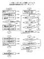
FIG.FIG. 2 shows a flowchart of processing on the caller side of an IP type Internet telephone system that uses the
When the calling
[0114]
If not registered (S302, NO), the originating
As a response to the IP address request, when the IP address and telephone number from the
[0115]
On the other hand, when the telephone number and IP address of the receiving
[0116]
When the IP-IP connection is completed, the receiver-
When the user of the
[0117]
The originating
For example, when an abnormality in the transfer rate is detected by the calling
[0118]
After disconnecting the IP-IP connection, the originating
[0119]
Further, for example, when a transfer rate abnormality is detected by the receiving
In addition, when the user of the
[0120]
FIG.FIG. 2 shows a flowchart of processing on the receiving side of an IP type Internet telephone system that uses the
When the receiving
[0121]
The receiving
If not registered (NO in S324), the receiving
[0122]
On the other hand, when the telephone number and IP address of the calling side are registered in the
When the IP-IP connection is completed, the receiver-
[0123]
When the user of the telephone set 12 performs on-hook during a call (S328, YES), the receiving
[0124]
Further, the receiving
For example, if an abnormality in the transfer rate is detected in the calling
[0125]
After disconnecting the IP-IP connection, the receiving
[0126]
Further, for example, when an abnormality in the transfer rate is detected by the originating
In addition, when the user of the
[0153]
The above-described Internet telephone system of the present embodiment has the same operation as that of the telephone normally used when the calling telephone makes a call with the receiving telephone, and it is not connected to the computer managed on the network. It is not necessary to register this information in advance, and it is very convenient for users.
In the Internet telephone system of the present embodiment, since the user uses the Internet as a communication network, the telephone can be used at a low charge even at a long distance.
[0154]
In addition, since the Internet telephone system of the present embodiment is the same as when the telephone operation of the user is using the public line network, the user does not need to be aware of the communication network.
FIG.These show the block diagram of the computer as a communication apparatus of the internet telephone system which performs the telephone call using the internet.
[0155]
FIG.The computer has a
The
[0156]
The
The
[0157]
The
CD-
A program is installed in the
[0158]
The CD-
[0159]
【The invention's effect】
As described above, according to the Internet telephone system of the present invention, when a caller has a conversation with a receiver, the operation is the same as that of a normally used telephone, and his / her information is stored in a computer managed on the network. There is no need to register in advance, and it is very convenient for users.
[0160]
In addition, according to the Internet telephone system of the present invention, the user can use the telephone at a low charge even at a long distance because the user uses the Internet as a communication network.
Further, according to the Internet telephone system of the present invention, the user does not need to be aware of the communication network because the telephone operation of the user is the same as when using the public line network.
[0161]
Therefore, the present invention can be operated in the same way as a normally used telephone when dialing a third party telephone that the telephone user wants to talk to, and at a low charge using the Internet. It is possible to provide an Internet telephone system that can realize the conversation.
[Brief description of the drawings]
FIG. 1 is a principle configuration diagram of an Internet telephone system according to the present invention.
FIG. 2 is a diagram showing the configuration and operation of an embodiment of the Internet telephone system.
FIG. 3 is a configuration example of an Internet telephone system.
FIG. 4 is a diagram showing an operation of transmitting / receiving information between computers.
FIG. 5 is an example of information managed by an information storage unit.
FIG. 6 is an example of information transmitted / received between computers.
FIG. 7 is a diagram illustrating control between computers.
[Fig. 8]Reference diagramIt is.
FIG. 9 is a diagram showing an operation between a sending computer and a provider.
FIG. 10 is an example of information managed by an information storage unit.
FIG. 11 is a diagram illustrating an operation between providers.
FIG. 12 is a diagram showing an operation between a receiving-side provider and a computer.
FIG. 13 is a diagram illustrating an automatic switching operation between the Internet and a public line network.
FIG. 14 is a diagram showing an operation between an Internet telephone system and an existing telephone.
FIG. 15 is a diagram showing control between an Internet telephone system and an existing telephone.
FIG. 16 is a diagram showing an operation between the Internet telephone system and an existing telephone.
FIG. 17 is a diagram showing control between an Internet telephone system and an existing telephone.
FIG. 18 is a diagram showing an operation of an answering machine.
FIG. 19 is a diagram illustrating an analog / digital conversion operation.
FIG. 20 is a diagram showing operations between computers.
FIG. 21 is a diagram illustrating an operation between a receiving-side provider and a computer.
FIG. 22 is a flowchart showing processing of the IP Internet telephone system.
FIG. 23It is a flowchart which shows the process of the transmission side in IP type | mold internet telephone system.
FIG. 24It is a flowchart which shows the process of the receiving side in IP type | mold internet telephone system.
FIG. 25It is a block diagram of a communication apparatus.
FIG. 26It is an example of the conventional internet telephone system.
FIG. 27It is an example of the conventional internet telephone system.
[Explanation of symbols]
1 First call device
2 Second call device
3 First communication device
4 Second communication device
5 Public network
6 First mediation device
7 Second mediation device
8 Internet
11 Telephone
12 Telephone
13 Telephone
14 Calculator
15 Calculator
16 Public network
17 Provider
18 Provider
19 Internet
31 connections
32 Cutting part
33 Conversion unit
34 Communication Department
35 Registration Department
36 Monitoring unit
37 switching part
38 Power-on section
39 Information storage
51 connections
52 Communication Department
53 Cutting part
54 Registration Department
55 Information storage
61 Local network information
62 Provider information
63 Network information of the other side
71 Provider connection information
72 Answering machine information
101 computer
102 computer
103 Dedicated server
104 Management database
105 Internet
111 telephone
112 telephone
113 calculator
114 calculator
115 Management database
116 Management database
117 Internet
301 Control unit
302 memory unit
303 Display unit
304 Input unit
305 CDROM drive unit
306 disk unit
400 CDROM
Claims (3)
Translated fromJapanese該通信装置は、
電話機及び通信装置からの発信により、通話相手側の通信装置及び仲介装置に公衆回線網を介してダイヤリングによる接続を行う接続手段と、
公衆回線網及びインターネットを利用してデータの通信を行う通信手段と、
インターネットを利用した通話中に、インターネット上の通信データを監視する監視手段と、
該監視手段にて通信データの転送レートが保証できない状態が検出された場合、インターネットを利用した通話を公衆回線網を利用した通話に切り替える切替手段と、
を有し、
該接続手段が該通話相手側の通信装置に接続を行った後に該通信手段が該通話相手側のIPアドレスを要求し、該接続手段が該仲介装置に接続を行った後に該IPアドレスを該仲介装置に通知することにより、インターネット上の通信路を確立することを特徴とするインターネット電話システム。Internet telephones and communication devices connected to the intermediary device via a public line network, by establishing a communication path over the Internet viathe mediation device, to realize mutual communication by telephone and the communication device over the Internet In the telephone system,
The communication device
A connection means for making a connection by dialing to acommunication device and an intermediary device on the other party side of a telephone call by calling from a telephone and a communication device;
A communication means for communicating data using a public network and the Internet;
Monitoring means for monitoring communication data on the Internet during a call using the Internet;
Switching means for switching a call using the Internet to a call using a public network when a state in which the transfer rate of communication data cannot be guaranteed is detected by the monitoring means;
Have
After the connection means connects to the communication apparatus on the other party side, the communication means requests the IP address on the other party side, and after the connection means connects to the intermediary apparatus, the IP address is An internet telephone system characterizedin that a communication path on the internet is established by notifying an intermediary device .
電話機からの発信により、通話相手側の通信装置及び仲介装置に公衆回線網を介してダイヤリングによる接続を行う接続手段と、 A connection means for making a connection by dialing to a communication apparatus and an intermediary apparatus on the other side of the telephone call through a public line network by calling from the telephone;
公衆回線網及びインターネットを利用してデータの通信を行う通信手段と、 A communication means for communicating data using a public network and the Internet;
インターネットを利用した通話中に、インターネット上の通信データを監視する監視手段と、 Monitoring means for monitoring communication data on the Internet during a call using the Internet;
該監視手段にて通信データの転送レートが保証できない状態が検出された場合、インターネットを利用した通話を公衆回線網を利用した通話に切り替える切替手段と、 Switching means for switching a call using the Internet to a call using a public network when a state in which the transfer rate of communication data cannot be guaranteed is detected by the monitoring means;
を有し、 Have
該接続手段が該通話相手側の通信装置に接続を行った後に該通信手段が該通話相手側のIPアドレスを要求し、該接続手段が該仲介装置に接続を行った後に該IPアドレスを該仲介装置に通知することにより、インターネット上の通信路を確立することを特徴とする通信装置。 After the connection means connects to the communication apparatus on the other party side, the communication means requests the IP address on the other party side, and after the connection means connects to the intermediary apparatus, the IP address is A communication device that establishes a communication path on the Internet by notifying an intermediary device.
該通信装置を、 The communication device
電話機及び通信装置からの発信により、通話相手側の電話機及び仲介装置に公衆回線網を介してダイヤリングによる接続を行わせる接続手段と、 A connection means for causing a telephone and an intermediary device on the other party side to make a connection by dialing via a public line network by calling from a telephone and a communication device;
公衆回線網及びインターネットを利用してデータの通信を行わせる通信手段と、 A communication means for performing data communication using a public network and the Internet;
インターネットを利用した通話中に、インターネット上の通信データを監視する監視手段と、 Monitoring means for monitoring communication data on the Internet during a call using the Internet;
該監視手段にて通信データの転送レートが保証できない状態が検出された場合、インターネットを利用した通話を公衆回線網を利用した通話に切り替える切替手段と、 Switching means for switching a call using the Internet to a call using a public network when a state in which the transfer rate of communication data cannot be guaranteed is detected by the monitoring means;
して動作させ、 And operate
該接続手段が該通話相手側の通信装置に接続を行った後に該通信手段が該通話相手側のIPアドレスを要求し、該接続手段が該仲介装置に接続を行った後に該IPアドレスを該仲介装置に通知することにより、インターネット上の通信路を確立するプログラムを記憶したコンピュータ読み取り可能な記憶媒体。 After the connection means connects to the communication apparatus on the other party side, the communication means requests the IP address on the other party side, and after the connection means connects to the intermediary apparatus, the IP address is A computer-readable storage medium storing a program for establishing a communication path on the Internet by notifying an intermediary device.
Priority Applications (2)
| Application Number | Priority Date | Filing Date | Title |
|---|---|---|---|
| JP28402697AJP3685912B2 (en) | 1997-10-16 | 1997-10-16 | Internet phone system |
| US09/039,246US6819663B2 (en) | 1997-10-16 | 1998-03-16 | Internet telephone system |
Applications Claiming Priority (1)
| Application Number | Priority Date | Filing Date | Title |
|---|---|---|---|
| JP28402697AJP3685912B2 (en) | 1997-10-16 | 1997-10-16 | Internet phone system |
Publications (2)
| Publication Number | Publication Date |
|---|---|
| JPH11122387A JPH11122387A (en) | 1999-04-30 |
| JP3685912B2true JP3685912B2 (en) | 2005-08-24 |
Family
ID=17673352
Family Applications (1)
| Application Number | Title | Priority Date | Filing Date |
|---|---|---|---|
| JP28402697AExpired - Fee RelatedJP3685912B2 (en) | 1997-10-16 | 1997-10-16 | Internet phone system |
Country Status (2)
| Country | Link |
|---|---|
| US (1) | US6819663B2 (en) |
| JP (1) | JP3685912B2 (en) |
Families Citing this family (35)
| Publication number | Priority date | Publication date | Assignee | Title |
|---|---|---|---|---|
| US20040091088A1 (en)* | 1996-08-23 | 2004-05-13 | Lee Weinstein | Network telephone communication |
| JP2000244581A (en)* | 1999-02-19 | 2000-09-08 | Fujitsu Ltd | Internet telephony hollowing system |
| JP3360041B2 (en)* | 1999-06-11 | 2002-12-24 | エヌイーシーインフロンティア株式会社 | Telephone equipment |
| US6832254B1 (en) | 1999-08-23 | 2004-12-14 | Nortel Networks Limited | Method and apparatus for associating an end-to-end call identifier with a connection in a multimedia packet network |
| US8448059B1 (en)* | 1999-09-03 | 2013-05-21 | Cisco Technology, Inc. | Apparatus and method for providing browser audio control for voice enabled web applications |
| US7457279B1 (en) | 1999-09-10 | 2008-11-25 | Vertical Communications Acquisition Corp. | Method, system, and computer program product for managing routing servers and services |
| US7092380B1 (en)* | 1999-10-22 | 2006-08-15 | Cisco Technology, Inc. | Method and system for providing voice communication over data networks |
| US6769020B2 (en)* | 1999-12-24 | 2004-07-27 | Matsushita Electric Industrial Co., Ltd. | Data terminal, data distribution system, and internet telephone system |
| CA2304353A1 (en)* | 2000-04-06 | 2001-10-06 | Stephen Murphy | Telephone call manager |
| JP3606445B2 (en)* | 2000-05-11 | 2005-01-05 | 日本電気株式会社 | Computer communication network and computer communication method |
| JP2002044181A (en)* | 2000-07-24 | 2002-02-08 | Yoshiyasu Mutou | Internet phone connection method and its system |
| US20020093674A1 (en)* | 2001-01-16 | 2002-07-18 | Ferlitsch Andy Rodney | Method and system for instant fax transmission |
| US6700884B2 (en) | 2001-06-28 | 2004-03-02 | Emerson, Iii Harry E. | Integrating the Internet with the public switched telephone network |
| US6928070B2 (en)* | 2001-06-28 | 2005-08-09 | Emerson, Iii Harry E. | Integrating the internet with the public switched telephone network |
| US6704305B2 (en) | 2001-06-28 | 2004-03-09 | Emerson, Iii Harry E. | Integrated device for integrating the internet with the public switched telephone network |
| US7327720B2 (en)* | 2001-07-18 | 2008-02-05 | Emerson Iii Harry E | Integrated telephone central office systems for integrating the internet with the public switched telephone network |
| US20030016661A1 (en)* | 2001-07-18 | 2003-01-23 | Emerson Harry E. | Telephone switching system for integrating the internet with the public switched telephone network |
| US6697357B2 (en) | 2001-08-10 | 2004-02-24 | Emerson, Iii Harry E. | Call management messaging system for integrating the internet with the public switched telephone network |
| JP3857572B2 (en)* | 2001-11-20 | 2006-12-13 | 沖電気工業株式会社 | IP telephone apparatus and IP telephone apparatus search method |
| US7415026B2 (en)* | 2002-02-04 | 2008-08-19 | Qualcomm Incorporated | Method and apparatus for session release in a communication system |
| US7529200B2 (en)* | 2003-07-24 | 2009-05-05 | 3E Technologies International, Inc. | Method and system for fast setup of group voice over IP communications |
| TW200539641A (en)* | 2004-02-19 | 2005-12-01 | Matsushita Electric Industrial Co Ltd | Connected communication terminal, connecting communication terminal, session management server and trigger server |
| MY145725A (en)* | 2004-07-30 | 2012-03-30 | Ericsson Telefon Ab L M | Method and system for retrieving network addresses in hybrid telecommunication networks |
| US7852831B2 (en) | 2005-02-22 | 2010-12-14 | Akbar Imran M | Method and system for providing private virtual secure Voice over Internet Protocol communications |
| US7453869B1 (en)* | 2005-02-24 | 2008-11-18 | Sprint Communications Company L.P. | Carrier based call release |
| US7801968B2 (en)* | 2005-04-29 | 2010-09-21 | Microsoft Corporation | Delegated presence for unified messaging/unified communication |
| US8274970B2 (en)* | 2005-11-14 | 2012-09-25 | Broadcom Corporation | Voice communication device with PSTN and internet pathway analysis, selection and handoff |
| US8483100B2 (en)* | 2005-11-14 | 2013-07-09 | Broadcom Corporation | Communication device supporting both internet and public switched telephone network telephony |
| US7778261B2 (en)* | 2005-11-15 | 2010-08-17 | ArcSoft (Shanghai) Technology | Using PSTN to communicate IP address for point-to-point text, voice, video, or data communication |
| US20070147399A1 (en)* | 2005-11-15 | 2007-06-28 | Arcsoft (Shanghai) Technology Company, Ltd | Using Secondary Channels to Communicate IP Addresses for Point-To-Point Communication |
| US20070160034A1 (en)* | 2006-01-06 | 2007-07-12 | D.S.P. Group Ltd | Dual-protocol dual port telephone and method to connect another dual-protocol dual port telephone via IP network directly and without installation |
| US20080159266A1 (en)* | 2006-12-30 | 2008-07-03 | Arcsoft (Shanghai) Technology Company, Ltd | Determining Pairings of Telephone Numbers and IP Addresses from Caching and Peer-To-Peer Lookup |
| US20080310399A1 (en)* | 2007-06-12 | 2008-12-18 | Imvocal, Inc. | Methods and systems for connecting phones to internet users |
| JP2010534969A (en)* | 2007-07-25 | 2010-11-11 | イントラコ テクノロジー ピーティーイー リミテッド | Content management and distribution system |
| JP2011223531A (en)* | 2010-04-14 | 2011-11-04 | Sony Computer Entertainment Inc | Portable information terminal, network connection method, network connection system, and server |
Family Cites Families (24)
| Publication number | Priority date | Publication date | Assignee | Title |
|---|---|---|---|---|
| CA2139081C (en)* | 1994-12-23 | 1999-02-02 | Alastair Gordon | Unified messaging system and method |
| US5610910A (en)* | 1995-08-17 | 1997-03-11 | Northern Telecom Limited | Access to telecommunications networks in multi-service environment |
| US6243373B1 (en)* | 1995-11-01 | 2001-06-05 | Telecom Internet Ltd. | Method and apparatus for implementing a computer network/internet telephone system |
| JP3911712B2 (en) | 1995-12-18 | 2007-05-09 | ソニー株式会社 | Call system and call method |
| JP3671488B2 (en) | 1995-12-18 | 2005-07-13 | ソニー株式会社 | Call system and call method |
| US6128293A (en)* | 1995-12-20 | 2000-10-03 | Nortel Networks Corporation | Multiservice access management system |
| US5732078A (en)* | 1996-01-16 | 1998-03-24 | Bell Communications Research, Inc. | On-demand guaranteed bandwidth service for internet access points using supplemental user-allocatable bandwidth network |
| US6069890A (en)* | 1996-06-26 | 2000-05-30 | Bell Atlantic Network Services, Inc. | Internet telephone service |
| US5708699A (en)* | 1996-05-29 | 1998-01-13 | At&T | Hybrid access architecture for voice messaging systems |
| US6078579A (en)* | 1996-07-25 | 2000-06-20 | Wjw Technologies Inc. | Telephonic systems for communication over computer networks |
| US5918019A (en)* | 1996-07-29 | 1999-06-29 | Cisco Technology, Inc. | Virtual dial-up protocol for network communication |
| US6295357B1 (en)* | 1996-09-06 | 2001-09-25 | Data Race, Inc. | System and method for ringing other subscriber telephones connected to a telephone line during data communications on the telephone line |
| US6011794A (en)* | 1996-09-09 | 2000-01-04 | Netplus Communications Corp. | Internet based telephone apparatus and method |
| US5974043A (en)* | 1996-09-16 | 1999-10-26 | Solram Electronics Ltd. | System and method for communicating information using the public switched telephone network and a wide area network |
| US5907547A (en)* | 1996-10-24 | 1999-05-25 | At&T Corp | System and method for establishing internet communications links |
| US6307853B1 (en)* | 1996-11-21 | 2001-10-23 | Net2Phone, Inc. | Re-routing telephony communications traffic through a private branch exchange to a data network |
| US6064653A (en)* | 1997-01-07 | 2000-05-16 | Bell Atlantic Network Services, Inc. | Internetwork gateway to gateway alternative communication |
| US5910946A (en)* | 1997-01-13 | 1999-06-08 | Samsung Electronics Co., Ltd. | Wireless internet network architecture for voice and data communications |
| US5991292A (en)* | 1997-03-06 | 1999-11-23 | Nortel Networks Corporation | Network access in multi-service environment |
| US6026087A (en)* | 1997-03-14 | 2000-02-15 | Efusion, Inc. | Method and apparatus for establishing a voice call to a PSTN extension for a networked client computer |
| US6208638B1 (en)* | 1997-04-01 | 2001-03-27 | J 2 Global Communications, Inc. | Method and apparatus for transmission and retrieval of facsimile and audio messages over a circuit or packet switched network |
| US6181690B1 (en)* | 1997-07-18 | 2001-01-30 | At&T Corp. | Toll-free internet service |
| US6272126B1 (en)* | 1997-07-24 | 2001-08-07 | Bell Atlantic Network Services, Inc. | Internetwork telephony with enhanced features |
| US6078581A (en)* | 1997-09-12 | 2000-06-20 | Genesys Telecommunications Laboratories, Inc. | Internet call waiting |
- 1997
- 1997-10-16JPJP28402697Apatent/JP3685912B2/ennot_activeExpired - Fee Related
- 1998
- 1998-03-16USUS09/039,246patent/US6819663B2/ennot_activeExpired - Fee Related
Also Published As
| Publication number | Publication date |
|---|---|
| JPH11122387A (en) | 1999-04-30 |
| US6819663B2 (en) | 2004-11-16 |
| US20020057672A1 (en) | 2002-05-16 |
Similar Documents
| Publication | Publication Date | Title |
|---|---|---|
| JP3685912B2 (en) | Internet phone system | |
| US6501750B1 (en) | Method and device for device-to-device enablement of camp-on capability | |
| CN101455062A (en) | User interface for communication equipment | |
| KR100331784B1 (en) | Multiple function telephone comprising internet phone, gateway and normal telephone, and its communication method | |
| KR20000077258A (en) | Handheld television telephone terminal | |
| WO2004006512A1 (en) | Communication systems and methods | |
| JPH10240656A (en) | Incoming call control method | |
| RU2003102504A (en) | SECURITY SYSTEM AND METHOD OF TERMINAL OPERATION, AT LEAST, IN TWO COMMUNICATION MODES | |
| CN101291371B (en) | Method and device for call processing | |
| JP3360041B2 (en) | Telephone equipment | |
| JP2002111906A (en) | Answer detection for ip-based telephone using passive detection | |
| KR100549782B1 (en) | Call center system compatible with universal private exchange | |
| KR100386930B1 (en) | Apparatus and method for interfacing internet telephone | |
| JP3801877B2 (en) | Virtual private branch exchange apparatus and call control method thereof | |
| US20030059014A1 (en) | Multi-media communication management system with caller managed hold system | |
| KR20040046338A (en) | System for providing ring-back hyper image and method of providing ring-back hyper image using the same | |
| KR100442436B1 (en) | Method for user authentication using IVR service in internet telephone network | |
| JP2004129157A (en) | Telephone equipment | |
| KR100354446B1 (en) | program upgrading apparatus and method of digital phone | |
| KR100743516B1 (en) | Mobile Internet Phone Service System and its Service Method and VIO IP Phone Used in It | |
| JPH11205475A (en) | Intercom equipment | |
| JPH09162994A (en) | Telephone terminal equipment and communication center device | |
| JP2003258999A (en) | Ip telephone system and terminal adapter | |
| KR100356463B1 (en) | Internet phone with automatic receiving fuction and methde thereof | |
| JP3803517B2 (en) | Multi-function telephone and multi-function telephone exchange system |
Legal Events
| Date | Code | Title | Description |
|---|---|---|---|
| A977 | Report on retrieval | Free format text:JAPANESE INTERMEDIATE CODE: A971007 Effective date:20050204 | |
| A131 | Notification of reasons for refusal | Free format text:JAPANESE INTERMEDIATE CODE: A131 Effective date:20050222 | |
| A521 | Written amendment | Free format text:JAPANESE INTERMEDIATE CODE: A523 Effective date:20050421 | |
| TRDD | Decision of grant or rejection written | ||
| A01 | Written decision to grant a patent or to grant a registration (utility model) | Free format text:JAPANESE INTERMEDIATE CODE: A01 Effective date:20050531 | |
| A61 | First payment of annual fees (during grant procedure) | Free format text:JAPANESE INTERMEDIATE CODE: A61 Effective date:20050601 | |
| R150 | Certificate of patent or registration of utility model | Free format text:JAPANESE INTERMEDIATE CODE: R150 | |
| FPAY | Renewal fee payment (event date is renewal date of database) | Free format text:PAYMENT UNTIL: 20090610 Year of fee payment:4 | |
| FPAY | Renewal fee payment (event date is renewal date of database) | Free format text:PAYMENT UNTIL: 20100610 Year of fee payment:5 | |
| FPAY | Renewal fee payment (event date is renewal date of database) | Free format text:PAYMENT UNTIL: 20110610 Year of fee payment:6 | |
| FPAY | Renewal fee payment (event date is renewal date of database) | Free format text:PAYMENT UNTIL: 20120610 Year of fee payment:7 | |
| LAPS | Cancellation because of no payment of annual fees |