JP3684285B2 - Tunable slot antenna - Google Patents
Tunable slot antennaDownload PDFInfo
- Publication number
- JP3684285B2 JP3684285B2JP05482597AJP5482597AJP3684285B2JP 3684285 B2JP3684285 B2JP 3684285B2JP 05482597 AJP05482597 AJP 05482597AJP 5482597 AJP5482597 AJP 5482597AJP 3684285 B2JP3684285 B2JP 3684285B2
- Authority
- JP
- Japan
- Prior art keywords
- conductor
- layer
- box
- slot antenna
- antenna
- Prior art date
- Legal status (The legal status is an assumption and is not a legal conclusion. Google has not performed a legal analysis and makes no representation as to the accuracy of the status listed.)
- Expired - Fee Related
Links
Images


Classifications
- H—ELECTRICITY
- H01—ELECTRIC ELEMENTS
- H01Q—ANTENNAS, i.e. RADIO AERIALS
- H01Q13/00—Waveguide horns or mouths; Slot antennas; Leaky-waveguide antennas; Equivalent structures causing radiation along the transmission path of a guided wave
- H01Q13/10—Resonant slot antennas
- H01Q13/103—Resonant slot antennas with variable reactance for tuning the antenna
Landscapes
- Waveguide Aerials (AREA)
- Variable-Direction Aerials And Aerial Arrays (AREA)
- Support Of Aerials (AREA)
Description
Translated fromJapanese【0001】
【発明の属する技術分野】
本発明は、携帯無線端末機に適用して好適なアンテナに関し、特に同軸共振器を利用したスロットアンテナに関する。
【0002】
【従来の技術】
携帯無線端末機は、携帯性向上の観点から小型化、薄型化が進んでおり、同時にそのような端末機に搭載するための小型アンテナが多種類開発されている。その中で、同軸共振器を利用したスロットアンテナは、突起物を持たずに内蔵可能な特長を持っており、特にその中心導体(帯状導体)を共振器外箱(扁平導体箱)と非接触にする構造によって小型化した同軸共振型スロットアンテナが特願平7−227959願書によって提案されている。その構造の例を図10に示す。
【0003】
当該アンテナは、全体として直方体である扁平導体箱1と、当該導体箱の内部空間の共振軸方向に沿い、かつ、扁平導体箱1と絶縁して配設された細長い帯状導体3と、扁平導体箱1の上面に帯状導体3と交差して形成された電波送受用のスロット2とによって構成され、帯状導体3に設定された結合部10と扁平導体箱1の壁面との間で高周波給電回路7から高周波電力の給電が行なわれる。当該アンテナは、厚さを数mm以下と極めて薄くすることができ、更に通常の多層基板製造プロセスを用いて作製可能であり、端末の小型化、低コスト化に大きな効果を有している。
【0004】
当該アンテナは、共振器構造を含むので、その体積とインピーダンス整合帯域は、正比例の関係にある。従って、複数の搬送波周波数を用いて大容量化した広帯域無線通信システムの端末機に適用する場合、アンテナが備えるべきインピーダンス整合周波数帯域が拡大し、アンテナの体積が増大するという問題点があった。
【0005】
【発明が解決しようとする課題】
通常、基地局と端末機の間では、送受信共用で一つの周波数を用いるか、又は送受別で二つの周波数を用いて通話が行なわれるため、そのとき使用する周波数帯域は、システム全体の周波数帯域よりも極めて狭い。従って、通話の度にアンテナのインピーダンス整合中心周波数をその通話の際に用いる周波数に適応的に変化させることが可能であれば、アンテナが備えるべき周波数帯域を減少させることができ、アンテナの体積を小さくすることができる。尤も、アンテナのインピーダンス整合中心周波数を適応的に変化させる技術が特開昭63−294107号公報に開示されている。しかし、同公報は、同軸共振器型スロットアンテナの構造には言及していない。
【0006】
本発明の目的は、アンテナのインピーダンス整合中心周波数を変化させることが可能な新規の同軸共振型スロットアンテナを提供することにある。
【0007】
【課題を解決するための手段】
本発明の前記課題は、帯状導体の高周波電力が供給される結合部から遠い方の端を含むその近傍の一点(以下「容量接続部」という)と扁平導体箱の壁面との間に可変容量素子を接続することによって効果的に解決することができる。このような手段を採用すれば、可変容量素子の容量値を変えることによってアンテナのインピーダンス整合中心周波数、即ち、共振周波数を変えることが可能となるからである。
【0008】
前記願書に記載されているように、同軸共振型スロットアンテナの共振周波数は、ほぼ帯状導体の長さ(凡そ共振波長/4)によって決まる。一方、帯状導体の先端に集中定数負荷を装加することにより、等価的に帯状導体の長さを電気的に変化させる技術が従来から良く知られている(例えば昭和55年10月オーム社発行電子通信学会編「アンテナ工学ハンドブック」第43頁参照)。帯状導体の長さが見掛け上変化するのは、給電線として電位を有する帯状導体の先端から接地電位へ伸びる電気力線の密度が帯状導体の先端部に接続された集中定数負荷により変化するためである。本発明においては、集中定数負荷として、可変容量素子を用いる。可変容量素子は、その容量値が直流電圧を印加することによって変化する素子であることが望ましい。そのような素子として、例えば可変容量ダイオードを用いることができる。
【0009】
前記容量接続部の上方の扁平導体箱上面に小穴をあけ、短い線導体の一方の端を容量接続部に接続し、他方の端を小穴から出せば、他方の端は、容量接続部と同電位になる。また、扁平導体箱の壁面はどこも接地電位である。従って、可変容量素子の帯状導体への接続は、例えば、同素子を小穴から出した線導体の他方の端と小穴近くの壁面との間に接続することによって実現することができる。
【0010】
このようなアンテナを無線通信システムの端末機に用いることにより、通話の都度設定される無線周波数にアンテナの共振周波数を同調させることが可能となる。この場合、アンテナの周波数帯域は、通話に必要とする帯域があればよいので、無線通信システムが有する周波数帯域全体に比べて極めて狭いものとなる。従って、当該周波数帯域全体をカバーするアンテナに比べてその体積を小さくすることができ、それによって端末機へのアンテナ内蔵が容易となる。なお、前記では可変容量素子を接続するための線導体を扁平導体箱上面に引き出したが、これに限らず、線導体を扁平導体箱の底面又は側面に引き出すことが云うまでもなく可能であり、同様の効果を得ることができる。
【0011】
帯状導体の結合部と容量接続部とは直流では同電位になるので、可変容量素子に印加する直流電圧の供給部位を結合部と一致させることが可能である。この場合、結合部に直流電圧を重畳した高周波電力が供給されるが、そのような直流電圧の重畳は、例えば、高周波給電回路の出力端子が直流で開放状態であるときに高周波電流の流出を阻止する素子を介して電圧可変の直流電源(以下「可変直流電源」という)の出力端子を結合部に接続することによって達成される。
【0012】
次に、本発明のアンテナは、小型にすることができるので高周波回路基板に搭載し、関連する配線や素子及び回路と一体化することができる。これらの相互間を極めて接近して配置することが可能となり、GHz帯で用いるのに好ましい同軸共振型スロットアンテナを実現することができる。
【0013】
また、本発明のアンテナは、多層回路基板を用いて構成することができ、製造が容易な実用性の高いアンテナを得ることできる。その場合にも関連する配線や素子及び回路との一体化が可能であり、前記と同様、GHz帯で用いるのに好ましい同軸共振型スロットアンテナを実現することができる。
【0014】
【発明の実施の形態】
以下、本発明に係る同軸共振型スロットアンテナの実施の形態を図面に示した幾つかの実施例を参照して更に詳細に説明する。なお、図1〜図10における同一の記号は、同一物又は類似物を表示するものとする。
【0015】
【実施例】
<実施例1>
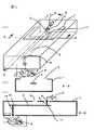
扁平導体箱の上面に可変容量素子を配置し、結合部を箱の外部に引出すための島状導体を同箱低面に設けた同軸共振型スロットアンテナを図1に示す。図1aは、その斜視図、図1bはA−A線断面図、図1cはB−B線断面図である。図1において、6は可変容量素子、11は、帯状導体3上に設けた容量接続部、4は、容量接続部11の真上の扁平導体箱1上面にスロット部位を避けて形成した島状導体、5は、容量接続部11と島状導体4とを電気的に結ぶためのスルーホール、14は、結合部10の真下の扁平導体箱1の底面に形成した島状導体、13は、結合部10と島状導体14を電気的に結ぶためのスルーホール、8は、高周波電流の流出を阻止するための低域通過型フィルタ、9は、可変直流電源を示す。可変容量素子6として、印加直流電圧によって容量が変化する可変容量ダイオードを採用した。なお、導体箱1内部は、帯状導体3を固定するための絶縁物で充填されているが、絶縁物の図示を省略した。
【0016】
島状導体4,14は、いずれも導体箱1の壁面にあけた小穴の中に同壁面に接触しないように形成されている。可変容量素子6は、島状導体4とその近傍の導体箱1壁面の一点との間に接続されている。結合部10の引出し先が島状導体14であり、島状導体14に高周波給電回路7の出力端子と、低域通過型フィルタ8の一方の端子が接続され、同フィルタの他方の端子に可変直流電源9が接続されている。給電回路7には、同出力端子に容量素子が接続され、高周波電力が同容量素子を介して出力端子から出力されるものを用いた。従って、出力端子は、直流で開放状態にある。可変容量素子6への直流電圧の印加は、低域通過型フィルタ8を介して可変直流電源9から島状導体14に直流電圧を供給することによって行なわれる。
【0017】
可変容量素子6は、帯状導体3の結合部10から遠い方の端近くの容量接続部11と接地(導体箱1の壁面)との間に容量を付加する役割を果たすため、容量接続部11での電気力線の密度が、可変容量素子6を接続しない場合と比べて増加し、この電気力線密度の増加を補償するように容量接続部11近辺の帯状導体3上に誘起する電流密度が増加する。結果として、あたかも帯状導体3の長さが変化したようになり、共振周波数、即ちインピーダンス整合中心周波数が変化する。
【0018】
可変容量素子6の容量値は、印加直流電圧の値によって変化させることができるので、結局、可変直流電源9の電圧値を変えることによって共振周波数を変化させることができる。従って、通話の度に設定される無線周波数に応じて可変直流電源9の電圧値を変化させることにより、無線周波数を共振周波数に一致させることができる。それによってアンテナの周波数帯域を通話に必要な帯域に制限することができ、アンテナの体積を小さくすることができる。なお、可変直流電源9は、電圧制御回路(図示せず)の制御を受けて電圧を変える。電圧制御回路は、無線周波数に対応した電圧値を指示する制御信号を生成し、可変直流電源9は、同制御信号に従って所定の直流電圧を発生する。可変直流電源9は、制御信号を入力するための制御端子(図示せず)を有している。
【0019】
本構造は、従来技術の同軸共振型スロットアンテナと同様に扁平な薄板平面構造とすることが可能であり、携帯無線端末機等の高周波回路基板に搭載することによって外部突起を持たない内蔵アンテナの形態とすることができる。
【0020】
<実施例2>
実施例1における扁平導体箱の内部に誘電体材料を充填した一実施例を図2に示す。同図において、12は誘電体材料である。可変容量素子6を接続した場合でも、それがない場合(前記願書参照)と同様に、導体箱1の内部の電磁界が誘電体材料の比誘電率の平方根に逆比例して短縮されるので、誘電体材料がない同じ共振周波数のアンテナ(実施例1)に比べてアンテナ寸法を短縮することができる。
【0021】
<実施例3>
結合部の外部への引出しを扁平導体箱の側面から行なったアンテナの一実施例を図3に示す。図3において、15は、扁平導体箱1の側面に形成した半円状の端面スルーホールを示す。同スルーホールは、側面にあけた細長い孔の中に側面の導体面とは接触しないように形成され、結合部10が扁平導体箱1の長手方向に沿って端面スルーホール15と電気的に結合している。端面スルーホール15に高周波給電回路7の出力端子と低域通過フィルタ8の一方の端子が接続され、同フィルタの他方の端子に可変直流電源9が接続されている。
【0022】
本実施例によれば、端面スルーホール15が結合部の引出し先となると共に、同スルーホールの下部が扁平導体箱1の底面(接地電位)と同一面となる。従って、本アンテナを回路基板に実装することが容易となる。即ち、配線導体と接地導体面とが形成されている回路基板を用意し、底面を下にしてアンテナを同基板に載せると、底面に接地導体面を接触させると同時にそのまま端面スルーホール15に配線導体を接触させることができる。従って、通常の自動実装が可能となる。以上により、本実施例のアンテナは、実施例1の効果に併せ、適用する端末機の製造コストを低減する効果を有する。
【0023】
<実施例4>
実施例1における低域通過フィルタをインダクタに変更した実施例を図4に示す。同図において、16はインダクタを示す。通常の高周波給電回路は、50オーム整合を前提にして設計されているので、本アンテナを現行の無線通信システムで採用されている数GHzの周波数帯域で用いる場合、インダクタ16のインダクタンスを30nH程度に選べば、そのインピーダンスは200オーム以上となり、インダクタ16を介し可変直流電源9に流出する高周波電流は、実用上問題ない程度となる。数GHz帯で30nH程度のインダクタンスは、チップ部品によって容易に製作可能であり、高価な低域通過型フィルタを安価なインダクタで代替することができる。本実施例のアンテナは、図1の実施例の効果に併せ、適用する端末の製造コストを低減する効果を有する。
【0024】
なお、可変容量素子6に可変容量ダイオードを用いているので、素子6に流れる直流電流は、逆バイアスの漏れ電流による極めて微小な電流であり、従って低域通過フィルタを抵抗に変更することも可能である。抵抗値を上記と同様に200オーム以上とすることにより、高周波電流の流出を実用上問題ない程度とすることができる。
【0025】
<実施例5>
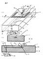
高周波回路基板に実装し、低域通過型フィルタ、可変直流電源及び高周波給電回路と一体化したアンテナの一実施例を図5に示す。同図において、21は、高周波回路基板、22は、端面スルーホール15に接続した給電用の配線導体、23は、配線導体22からの分岐配線導体、24は基板21の接地導体面を示す。可変容量素子6としてバラクタダイオードチップを用い、同チップを島状導体4と導体箱1上面に形成した小さい突起導体に挟んで実装した。
【0026】
アンテナは、扁平導体箱1の底面が導体面24と接触し、端面スルーホール15が配線導体22の一方の端部に接触するように実装されている。高周波給電回路7は、回路基板21上に実装され、配線導体22の他方の端部に給電回路7の出力端子が接続され、同回路の接地端子が導体面24の一点に接続されている。低域通過フィルタ8及び同フィルタに接続した可変直流電源9も回路基板21上に実装され、配線導体23の一方の端部に低域通過フィルタ8の一方の端子が接続され、直流電源9の接地端子が導体面24の一点に接続されている。
【0027】
本実施例のアンテナは、実施例3と同様、通常の自動実装が可能となるため、適用する端末機の製造コストを低減する効果を有する。
【0028】
<実施例6>
多層回路基板を用いて構成したアンテナの一実施例を図6に示す。多層回路基板は、誘電体材料による3枚の基板からなり、上から1,2枚目基板の表面をそれぞれ1,2層とし、3枚目基板の表面及び裏面をそれぞれ3,4層とした。図6aは、アンテナの構造を各層に分けて示した分解図、図6b,6cは、3枚の基板を接着して完成させたアンテナ(図示せず)のそれぞれA−A線断面図、B−B線断面図である。
【0029】
図6において、31,32,33,34は、順に第1,2,3,4層を示し、41,42,43は、それぞれ第1,2,3枚目の基板の誘電体材料を示す。また、40,44,46は、第1層31に形成したそれぞれ高周波電力給電用の配線導体、可変直流電源9へ制御信号を供給するための制御用配線導体、導体面、45は、第3層33に形成した内層導体面、47は、第4層34に形成した導体面、39は、帯状導体3の結合部と配線導体40を電気的に接続するための引出用のスルーホール、35は、導体面46、45を電気的に接続するための複数の側壁スルーホールを示す。
【0030】
スロット2は、導体面46の一部を削って形成され、帯状導体3は、第2層に形成した導体面を所定の形状に加工して形成されたものである。また、島状導体4は、スロット2とは重ならない導体面46の部分にあけた小穴の中に同導体面とは接触しないように形成されている。可変容量素子(バラクタダイオードチップ)6は、島状導体4とその近傍の導体面46上の一点の間に実装されている。スルーホール5,39は、共に第1,2層間に形成され、側壁スルーホール35は、基板41,42を相互に接着した後で第1,3層間に形成される。
【0031】
配線導体40とスルーホール39の接続点の近くで、スロット2から隔てられた部分にチップ化した低域通過フィルタ8とIC化した可変直流電源9とが実装されている。配線導体40の上記接続点から分岐した配線導体にフィルタ8の一方の端子が、フィルタ8の他方の端子に電源9の出力端子が、電源9の制御端子に制御用配線導体44がそれぞれ接続されている。
【0032】
複数の側壁スルーホール35と導体面45,46とで扁平導体箱1(箱としての図示を省略した)が形成されるように、スルーホール35は、スロット2、島状導体4、可変容量素子6を包含して方形状に配置され、その間隔がアンテナの共振波長の1/100をやや満たない値に設定される(通常、1/100以下に選ばれる)。ただし、帯状導体3は、スルーホール35の成す配列をやや越えて形成されるので、スルーホール35の間隔はこの部分で帯状導体3と接触しない程度に広げられている。導体面46、導体面45、複数のスルーホール35がそれぞれ扁平導体箱1の上面、底面、側面となる。
【0033】
以上の構造によって、導体箱1、フィルタ8、電源9、ダイオード6を一体化した同軸共振型スロットアンテナが多層基板中に形成される。本実施例のアンテナは、通常の多層基板製造プロセスを用いて製作することができるので、部品点数及び製造工数を削減することができ、従って、本アンテナを適用する携帯無線端末機の製造コストを低減することができる。
【0034】
<実施例7>
実施例6の帯状導体3の配置を変更し、これを第3層に形成した実施例を図7に示す。第2層には導体面が形成されず、第4層に扁平導体箱の底面となる導体面45が形成され、複数の側壁スルーホール35が、誘電体材料41,42,43を貫いて形成されている。
【0035】
本実施例によれば、複数の側壁スルーホール35、第1層の導体面46及び第4層の導体面45によって形成される共振器箱の体積が、図6に示した実施例と比べて大きくなるので、共振周波数を中心にしたアンテナのインピーダンス整合帯域を増加させることができる。従って、本実施例のアンテナは、携帯無線端末機のアンテナ系構造設計に対して余裕度を増加させる効果がある。
【0036】
なお、第2層と第3層を上下逆にし、導体面がない層を第3層とすることが可能であり、同様の効果を得ることができる。
【0037】
<実施例8>
実施例6の配線導体40,44の配置を第4層に移し、フィルタ8、電源9を第4層に実装した実施例を図8に示す。帯状導体3は、複数の側壁スルーホール35によって形成される方形の内側に置かれ、帯状導体3の結合部を配線導体40につなげるための引出用のスルーホール51が第2層と第4層の間に形成されている。導体面45には、スルーホール51を導体面45と電気的に絶縁して通過させるための通過孔52があけられている。導体面47は、配線導体40,44と接触しないように縮小して形成されている。
【0038】
本実施例によれば、第4層に形成される配線導体40やフィルタ8等のアンテナ給電系に対し、第1層に形成されるスロット2からの放射電磁波による干渉を抑制することができるので、本実施例のアンテナは、これを適用した携帯無線端末機の受信感度を向上させる効果がある。
【0039】
<実施例9>
実施例8の低域通過型フィルタを高周波チョークコイル(インダクタ)に変更した実施例を図9に示す。高周波チョークコイル53は、配線導体をジグザグ状に繰返し折曲げて形成したパターンによって実現される。
【0040】
本実施例によれば、フィルタが配線導体に置き代わることによって高周波部品が削減されるので、部品点数削減及び製造工数削減による低コスト化が実現される。本実施例のアンテナは、これを適用する携帯無線端末機の製造コストを低減する効果がある。
【0041】
【発明の効果】
本発明によれば、可変容量素子を帯状導体に付加することによってインピーダンス整合中心周波数(共振周波数)を変化させることが可能なアンテナを実現することができる。このアンテナを携帯無線端末機に適用すれば、通話の都度設定される無線周波数にアンテナの共振周波数を追従させること可能となり、従ってアンテナがカバーすべき周波数帯域を減少させることができ、それにより、アンテナの体積を小さくすることできる。携帯無線端末機は、本アンテナを適用することにより、突起部が解消して携帯性が向上すると共に、体積を小型化することができる。
【図面の簡単な説明】
【図1】本発明に係る同調型スロットアンテナの第1の実施例を説明するための斜視図及び断面図。
【図2】本発明の第2の実施例を示す説明するための斜視図及び断面図。
【図3】本発明の第3の実施例を示す説明するための斜視図及び断面図。
【図4】本発明の第4の実施例を示す説明するための斜視図及び断面図。
【図5】本発明の第5の実施例を示す説明するための斜視図及び断面図。
【図6】本発明の第6の実施例を示す説明するための斜視図及び断面図。
【図7】本発明の第7の実施例を示す説明するための斜視図及び断面図。
【図8】本発明の第8の実施例を示す説明するための斜視図及び断面図。
【図9】本発明の第9の実施例を示す説明するための斜視図及び断面図。
【図10】従来のスロットアンテナを説明するための斜視図。
【符号の説明】
1:扁平導体箱
2:スロット
3:帯状導体
4,14:島状導体
5,13,15,35,39,51:スルーホール
6:可変容量素子
7:高周波給電回路
8:高周波電流の流出を阻止する素子
9:可変直流電源
10:結合部
11:容量接続部[0001]
BACKGROUND OF THE INVENTION
The present invention relates to an antenna suitable for application to a portable wireless terminal, and more particularly to a slot antenna using a coaxial resonator.
[0002]
[Prior art]
Portable wireless terminals have been reduced in size and thickness from the viewpoint of improving portability, and at the same time, many types of small antennas have been developed for mounting on such terminals. Among them, slot antennas using coaxial resonators have the feature that they can be built without having protrusions, and the center conductor (strip conductor) is not in contact with the resonator outer box (flat conductor box). Japanese Patent Application No. 7-227959 proposes a coaxial resonance type slot antenna which is miniaturized by the structure to be realized. An example of the structure is shown in FIG.
[0003]
The antenna includes a
[0004]
Since the antenna includes a resonator structure, the volume and the impedance matching band are in a directly proportional relationship. Therefore, when applied to a terminal of a broadband wireless communication system that has a large capacity using a plurality of carrier frequencies, there is a problem that the impedance matching frequency band that the antenna should have is expanded and the volume of the antenna is increased.
[0005]
[Problems to be solved by the invention]
Usually, between a base station and a terminal, a single frequency is used for both transmission and reception, or a call is performed using two frequencies for transmission and reception, so the frequency band used at that time is the frequency band of the entire system. Is much narrower than Therefore, if the impedance matching center frequency of the antenna can be adaptively changed to the frequency used for the call for each call, the frequency band that the antenna should have can be reduced, and the volume of the antenna can be reduced. Can be small. However, Japanese Patent Application Laid-Open No. 63-294107 discloses a technique for adaptively changing the impedance matching center frequency of an antenna. However, this publication does not mention the structure of the coaxial resonator type slot antenna.
[0006]
An object of the present invention is to provide a novel coaxial resonance type slot antenna capable of changing the impedance matching center frequency of the antenna.
[0007]
[Means for Solving the Problems]
The object of the present invention is to provide a variable capacitance between one point in the vicinity including the end far from the coupling portion to which the high-frequency power of the strip conductor is supplied (hereinafter referred to as “capacitance connection portion”) and the wall surface of the flat conductor box. It can be effectively solved by connecting the elements. By adopting such means, it is possible to change the impedance matching center frequency of the antenna, that is, the resonance frequency, by changing the capacitance value of the variable capacitance element.
[0008]
As described in the application, the resonance frequency of the coaxial resonance type slot antenna is substantially determined by the length of the strip conductor (approximately the resonance wavelength / 4). On the other hand, a technique for equivalently electrically changing the length of the strip conductor by applying a lumped constant load to the tip of the strip conductor has been well known (for example, issued by Ohm Co., Ltd. in October 1980). (See
[0009]
If a small hole is made in the upper surface of the flat conductor box above the capacitance connection portion, one end of the short wire conductor is connected to the capacitance connection portion, and the other end is taken out from the small hole, the other end is the same as the capacitance connection portion. Become potential. Further, the wall surface of the flat conductor box is at ground potential everywhere. Therefore, the connection of the variable capacitance element to the strip-shaped conductor can be realized, for example, by connecting the element between the other end of the line conductor extending from the small hole and the wall surface near the small hole.
[0010]
By using such an antenna in a terminal of a wireless communication system, it becomes possible to tune the resonant frequency of the antenna to a wireless frequency set every time a call is made. In this case, since the frequency band of the antenna only needs to have a band necessary for the call, the frequency band of the antenna is extremely narrow compared to the entire frequency band of the wireless communication system. Accordingly, the volume of the antenna can be reduced as compared with the antenna that covers the entire frequency band, thereby facilitating the incorporation of the antenna into the terminal. In the above description, the line conductor for connecting the variable capacitance element is drawn out to the top surface of the flat conductor box. However, the present invention is not limited to this, and it goes without saying that the line conductor can be drawn out to the bottom surface or the side surface of the flat conductor box. The same effect can be obtained.
[0011]
Since the coupling portion and the capacitive connection portion of the strip conductor have the same potential in direct current, it is possible to match the supply portion of the direct current voltage applied to the variable capacitance element with the coupling portion. In this case, high-frequency power in which a DC voltage is superimposed is supplied to the coupling unit. Such superposition of the DC voltage causes, for example, a high-frequency current to flow out when the output terminal of the high-frequency power supply circuit is in a DC open state. This is achieved by connecting the output terminal of a voltage variable DC power supply (hereinafter referred to as “variable DC power supply”) to the coupling portion through the blocking element.
[0012]
Next, since the antenna of the present invention can be reduced in size, it can be mounted on a high-frequency circuit board and integrated with related wiring, elements, and circuits. These elements can be arranged very close to each other, and a coaxial resonance type slot antenna preferable for use in the GHz band can be realized.
[0013]
In addition, the antenna of the present invention can be configured using a multilayer circuit board, and an antenna with high practicality that is easy to manufacture can be obtained. In such a case as well, integration with related wiring, elements, and circuits is possible, and a coaxial resonance type slot antenna preferable for use in the GHz band can be realized as described above.
[0014]
DETAILED DESCRIPTION OF THE INVENTION
Hereinafter, embodiments of the coaxial resonant slot antenna according to the present invention will be described in more detail with reference to several examples shown in the drawings. In addition, the same symbol in FIGS. 1-10 shall display the same thing or a similar thing.
[0015]
【Example】
<Example 1>
FIG. 1 shows a coaxial resonance type slot antenna in which a variable capacitance element is arranged on the upper surface of a flat conductor box, and an island-shaped conductor is provided on the lower surface of the box to draw a coupling portion to the outside of the box. 1a is a perspective view thereof, FIG. 1b is a cross-sectional view taken along line AA, and FIG. 1c is a cross-sectional view taken along line BB. In FIG. 1, 6 is a variable capacitance element, 11 is a capacitance connection portion provided on the strip-shaped
[0016]
The island-
[0017]
The
[0018]
Since the capacitance value of the
[0019]
This structure can be a flat and thin flat plate structure similar to the coaxial resonance slot antenna of the prior art, and it is a built-in antenna that does not have external protrusions when mounted on a high-frequency circuit board such as a portable wireless terminal. It can be in the form.
[0020]
<Example 2>
FIG. 2 shows an embodiment in which a dielectric material is filled in the flat conductor box in the first embodiment. In the figure,
[0021]
<Example 3>
FIG. 3 shows an embodiment of an antenna in which the coupling portion is drawn out from the side of the flat conductor box. In FIG. 3,
[0022]
According to the present embodiment, the end surface through
[0023]
<Example 4>
FIG. 4 shows an embodiment in which the low-pass filter in the first embodiment is changed to an inductor. In the figure,
[0024]
Since a variable capacitance diode is used for the
[0025]
<Example 5>
FIG. 5 shows an embodiment of an antenna mounted on a high-frequency circuit board and integrated with a low-pass filter, a variable DC power supply, and a high-frequency power feeding circuit. In the figure, 21 is a high-frequency circuit board, 22 is a power supply wiring conductor connected to the end face through-
[0026]
The antenna is mounted such that the bottom surface of the
[0027]
Since the antenna of the present embodiment can be automatically mounted as usual as in the third embodiment, it has an effect of reducing the manufacturing cost of the terminal to be applied.
[0028]
<Example 6>
An embodiment of an antenna configured using a multilayer circuit board is shown in FIG. The multilayer circuit board is composed of three substrates made of a dielectric material, and the top and bottom surfaces of the first and second substrates are respectively 1 and 2 layers, and the front and back surfaces of the third substrate are 3 and 4 layers, respectively. . 6a is an exploded view showing the structure of the antenna divided into layers, and FIGS. 6b and 6c are cross-sectional views taken along line AA of an antenna (not shown) completed by bonding three substrates, B FIG.
[0029]
In FIG. 6,
[0030]
The
[0031]
Near the connection point between the
[0032]
The through
[0033]
With the above structure, a coaxial resonant slot antenna in which the
[0034]
<Example 7>
FIG. 7 shows an embodiment in which the arrangement of the strip-
[0035]
According to this embodiment, the volume of the resonator box formed by the plurality of side wall through-
[0036]
Note that the second layer and the third layer can be turned upside down, and the layer without the conductor surface can be the third layer, and the same effect can be obtained.
[0037]
<Example 8>
FIG. 8 shows an embodiment in which the arrangement of the
[0038]
According to the present embodiment, it is possible to suppress interference due to radiated electromagnetic waves from the
[0039]
<Example 9>
FIG. 9 shows an embodiment in which the low-pass filter of the eighth embodiment is changed to a high frequency choke coil (inductor). The high
[0040]
According to the present embodiment, the high-frequency components are reduced by replacing the filter with the wiring conductor, so that the cost can be reduced by reducing the number of components and the number of manufacturing steps. The antenna of the present embodiment has an effect of reducing the manufacturing cost of a portable wireless terminal to which this antenna is applied.
[0041]
【The invention's effect】
ADVANTAGE OF THE INVENTION According to this invention, the antenna which can change an impedance matching center frequency (resonance frequency) is realizable by adding a variable capacitance element to a strip | belt-shaped conductor. If this antenna is applied to a portable wireless terminal, it becomes possible to follow the resonance frequency of the antenna to the radio frequency set every time a call is made, and thus the frequency band to be covered by the antenna can be reduced. The volume of the antenna can be reduced. By applying this antenna, the portable wireless terminal can eliminate the protrusions and improve the portability, and can reduce the volume.
[Brief description of the drawings]
1A and 1B are a perspective view and a cross-sectional view for explaining a first embodiment of a tuned slot antenna according to the present invention.
FIGS. 2A and 2B are a perspective view and a cross-sectional view for explaining a second embodiment of the present invention. FIGS.
FIGS. 3A and 3B are a perspective view and a sectional view for explaining a third embodiment of the present invention. FIGS.
FIGS. 4A and 4B are a perspective view and a cross-sectional view for explaining a fourth embodiment of the present invention. FIGS.
FIGS. 5A and 5B are a perspective view and a cross-sectional view for explaining a fifth embodiment of the present invention. FIGS.
6A and 6B are a perspective view and a sectional view for explaining a sixth embodiment of the present invention.
7A and 7B are a perspective view and a sectional view for explaining a seventh embodiment of the present invention.
FIGS. 8A and 8B are a perspective view and a cross-sectional view for explaining an eighth embodiment of the present invention. FIGS.
FIGS. 9A and 9B are a perspective view and a sectional view for explaining a ninth embodiment of the invention. FIGS.
FIG. 10 is a perspective view for explaining a conventional slot antenna.
[Explanation of symbols]
1: flat conductor box 2: slot 3: strip-shaped
Claims (10)
Translated fromJapanese前記第1の導体面に島状導体が形成されると共に可変容量素子が実装され、かつ、島状導体と容量接続部を電気的に接続するための線状の導体が第1層と第2層の間に形成した容量接続用のスルーホールからなり、更に、一方の端子を結合部に接続した前記高周波電流流出阻止用の素子の他方の端子に前記直流電圧を生成する電圧可変直流電源が接続され、当該直流電源は、電源電圧を制御する電圧制御回路からの制御信号を受ける制御端子を備えていることを特徴とする請求項6に記載の同調型スロットアンテナ。A multilayer circuit board in which the first layer, the second layer, and the third layer are formed in order from the top by stacking the circuit boards, and the upper surface of the flat conductor box is formed on the first layer and the first conductor surface A slot formed by removing a part of the conductor surface, a strip-shaped conductor consisting of a third conductor surface formed in the second layer, and a bottom surface of the conductor box from the second conductor surface formed in the third layer. The side surface of the conductor box is an antenna composed of a plurality of side wall through holes provided through the second layer between the first layer and the third layer,
An island-shaped conductor is formed on the first conductor surface, a variable capacitance element is mounted, and a linear conductor for electrically connecting the island-shaped conductor and the capacitance connecting portion is the first layer and the second layer. A voltage variable direct-current power source that generates the direct-current voltage at the other terminal of the high-frequency current outflow prevention element that is formed of a through hole for connecting a capacitor formed between the layers and that has one terminal connected to the coupling portion. The tuned slot antenna according to claim 6, wherein the DC power supply is connected and has a control terminal for receiving a control signal from a voltage control circuit for controlling a power supply voltage.
Priority Applications (2)
| Application Number | Priority Date | Filing Date | Title |
|---|---|---|---|
| JP05482597AJP3684285B2 (en) | 1997-03-10 | 1997-03-10 | Tunable slot antenna |
| US09/035,848US6028561A (en) | 1997-03-10 | 1998-03-06 | Tunable slot antenna |
Applications Claiming Priority (1)
| Application Number | Priority Date | Filing Date | Title |
|---|---|---|---|
| JP05482597AJP3684285B2 (en) | 1997-03-10 | 1997-03-10 | Tunable slot antenna |
Publications (3)
| Publication Number | Publication Date |
|---|---|
| JPH10256826A JPH10256826A (en) | 1998-09-25 |
| JPH10256826A5 JPH10256826A5 (en) | 2004-09-02 |
| JP3684285B2true JP3684285B2 (en) | 2005-08-17 |
Family
ID=12981464
Family Applications (1)
| Application Number | Title | Priority Date | Filing Date |
|---|---|---|---|
| JP05482597AExpired - Fee RelatedJP3684285B2 (en) | 1997-03-10 | 1997-03-10 | Tunable slot antenna |
Country Status (2)
| Country | Link |
|---|---|
| US (1) | US6028561A (en) |
| JP (1) | JP3684285B2 (en) |
Cited By (1)
| Publication number | Priority date | Publication date | Assignee | Title |
|---|---|---|---|---|
| KR101707383B1 (en)* | 2016-07-29 | 2017-02-17 | 고려대학교 산학협력단 | On-chip slot antenna apparatus |
Families Citing this family (57)
| Publication number | Priority date | Publication date | Assignee | Title |
|---|---|---|---|---|
| KR100312364B1 (en)* | 1997-05-30 | 2001-12-28 | 가나이 쓰도무 | Tunable slot antenna |
| US6593887B2 (en) | 1999-01-25 | 2003-07-15 | City University Of Hong Kong | Wideband patch antenna with L-shaped probe |
| SE524641C2 (en)* | 2000-02-22 | 2004-09-07 | Smarteq Wireless Ab | An antenna device and an antenna assembly |
| JP3468201B2 (en)* | 2000-03-30 | 2003-11-17 | 株式会社村田製作所 | Surface mount antenna, frequency adjustment setting method of multiple resonance thereof, and communication device equipped with surface mount antenna |
| US6466176B1 (en)* | 2000-07-11 | 2002-10-15 | In4Tel Ltd. | Internal antennas for mobile communication devices |
| JP4928052B2 (en)* | 2000-08-16 | 2012-05-09 | ヴァレオ・レイダー・システムズ・インコーポレーテッド | Switched beam antenna architecture |
| JP2002076757A (en)* | 2000-09-01 | 2002-03-15 | Hitachi Ltd | Wireless terminal using slot antenna |
| FR2821503A1 (en)* | 2001-02-23 | 2002-08-30 | Thomson Multimedia Sa | ELECTROMAGNETIC SIGNAL RECEIVING AND / OR TRANSMISSION DEVICE FOR USE IN THE FIELD OF WIRELESS TRANSMISSIONS |
| US7174147B2 (en)* | 2001-04-11 | 2007-02-06 | Kyocera Wireless Corp. | Bandpass filter with tunable resonator |
| US7154440B2 (en)* | 2001-04-11 | 2006-12-26 | Kyocera Wireless Corp. | Phase array antenna using a constant-gain phase shifter |
| US7221243B2 (en)* | 2001-04-11 | 2007-05-22 | Kyocera Wireless Corp. | Apparatus and method for combining electrical signals |
| US7164329B2 (en) | 2001-04-11 | 2007-01-16 | Kyocera Wireless Corp. | Tunable phase shifer with a control signal generator responsive to DC offset in a mixed signal |
| US7394430B2 (en)* | 2001-04-11 | 2008-07-01 | Kyocera Wireless Corp. | Wireless device reconfigurable radiation desensitivity bracket systems and methods |
| US7746292B2 (en)* | 2001-04-11 | 2010-06-29 | Kyocera Wireless Corp. | Reconfigurable radiation desensitivity bracket systems and methods |
| US6690251B2 (en) | 2001-04-11 | 2004-02-10 | Kyocera Wireless Corporation | Tunable ferro-electric filter |
| US6937195B2 (en) | 2001-04-11 | 2005-08-30 | Kyocera Wireless Corp. | Inverted-F ferroelectric antenna |
| US7071776B2 (en) | 2001-10-22 | 2006-07-04 | Kyocera Wireless Corp. | Systems and methods for controlling output power in a communication device |
| US6864848B2 (en)* | 2001-12-27 | 2005-03-08 | Hrl Laboratories, Llc | RF MEMs-tuned slot antenna and a method of making same |
| US7184727B2 (en)* | 2002-02-12 | 2007-02-27 | Kyocera Wireless Corp. | Full-duplex antenna system and method |
| US7180467B2 (en) | 2002-02-12 | 2007-02-20 | Kyocera Wireless Corp. | System and method for dual-band antenna matching |
| US7176845B2 (en)* | 2002-02-12 | 2007-02-13 | Kyocera Wireless Corp. | System and method for impedance matching an antenna to sub-bands in a communication band |
| US7298228B2 (en)* | 2002-05-15 | 2007-11-20 | Hrl Laboratories, Llc | Single-pole multi-throw switch having low parasitic reactance, and an antenna incorporating the same |
| US7276990B2 (en)* | 2002-05-15 | 2007-10-02 | Hrl Laboratories, Llc | Single-pole multi-throw switch having low parasitic reactance, and an antenna incorporating the same |
| FR2840456A1 (en)* | 2002-05-31 | 2003-12-05 | Thomson Licensing Sa | IMPROVEMENT TO SLOT PLANAR ANTENNAS |
| US6664867B1 (en)* | 2002-07-19 | 2003-12-16 | Paratek Microwave, Inc. | Tunable electromagnetic transmission structure for effecting coupling of electromagnetic signals |
| US7154451B1 (en) | 2004-09-17 | 2006-12-26 | Hrl Laboratories, Llc | Large aperture rectenna based on planar lens structures |
| US7164387B2 (en)* | 2003-05-12 | 2007-01-16 | Hrl Laboratories, Llc | Compact tunable antenna |
| US7456803B1 (en) | 2003-05-12 | 2008-11-25 | Hrl Laboratories, Llc | Large aperture rectenna based on planar lens structures |
| US7245269B2 (en)* | 2003-05-12 | 2007-07-17 | Hrl Laboratories, Llc | Adaptive beam forming antenna system using a tunable impedance surface |
| US7253699B2 (en)* | 2003-05-12 | 2007-08-07 | Hrl Laboratories, Llc | RF MEMS switch with integrated impedance matching structure |
| US7068234B2 (en)* | 2003-05-12 | 2006-06-27 | Hrl Laboratories, Llc | Meta-element antenna and array |
| US7071888B2 (en)* | 2003-05-12 | 2006-07-04 | Hrl Laboratories, Llc | Steerable leaky wave antenna capable of both forward and backward radiation |
| US7720443B2 (en)* | 2003-06-02 | 2010-05-18 | Kyocera Wireless Corp. | System and method for filtering time division multiple access telephone communications |
| US7002517B2 (en)* | 2003-06-20 | 2006-02-21 | Anritsu Company | Fixed-frequency beam-steerable leaky-wave microstrip antenna |
| US7248845B2 (en)* | 2004-07-09 | 2007-07-24 | Kyocera Wireless Corp. | Variable-loss transmitter and method of operation |
| US20060080414A1 (en)* | 2004-07-12 | 2006-04-13 | Dedicated Devices, Inc. | System and method for managed installation of a computer network |
| US7348928B2 (en)* | 2004-12-14 | 2008-03-25 | Intel Corporation | Slot antenna having a MEMS varactor for resonance frequency tuning |
| US7126549B2 (en)* | 2004-12-29 | 2006-10-24 | Agc Automotive Americas R&D, Inc. | Slot coupling patch antenna |
| US7548762B2 (en)* | 2005-11-30 | 2009-06-16 | Kyocera Corporation | Method for tuning a GPS antenna matching network |
| US7307589B1 (en) | 2005-12-29 | 2007-12-11 | Hrl Laboratories, Llc | Large-scale adaptive surface sensor arrays |
| JP4131984B2 (en) | 2006-05-25 | 2008-08-13 | 松下電器産業株式会社 | Variable slot antenna and driving method thereof |
| WO2007138960A1 (en) | 2006-05-25 | 2007-12-06 | Panasonic Corporation | Variable slot antenna and method for driving same |
| DE102006038528B3 (en)* | 2006-08-17 | 2007-11-22 | Kathrein-Werke Kg | Tunable antenna e.g. patch antenna, for e.g. geostationary positioning, has electrically conductive structure galvanically or capacitively or serially connected with measuring surface or chassis by interconnecting electrical components |
| JP4874035B2 (en)* | 2006-09-05 | 2012-02-08 | 均 北吉 | Thin slot antenna with cavity, antenna feeding method, and RFID tag device using the same |
| US7868829B1 (en) | 2008-03-21 | 2011-01-11 | Hrl Laboratories, Llc | Reflectarray |
| US8436785B1 (en) | 2010-11-03 | 2013-05-07 | Hrl Laboratories, Llc | Electrically tunable surface impedance structure with suppressed backward wave |
| US8994609B2 (en) | 2011-09-23 | 2015-03-31 | Hrl Laboratories, Llc | Conformal surface wave feed |
| US9466887B2 (en) | 2010-11-03 | 2016-10-11 | Hrl Laboratories, Llc | Low cost, 2D, electronically-steerable, artificial-impedance-surface antenna |
| US8982011B1 (en) | 2011-09-23 | 2015-03-17 | Hrl Laboratories, Llc | Conformal antennas for mitigation of structural blockage |
| KR101856084B1 (en)* | 2011-11-18 | 2018-05-10 | 삼성전기주식회사 | Dielectric cavity antenna |
| US8878735B2 (en) | 2012-06-25 | 2014-11-04 | Gn Resound A/S | Antenna system for a wearable computing device |
| FR2997236A1 (en)* | 2012-10-23 | 2014-04-25 | Thomson Licensing | COMPACT SLIT ANTENNA |
| US9543660B2 (en)* | 2014-10-09 | 2017-01-10 | Apple Inc. | Electronic device cavity antennas with slots and monopoles |
| US9710746B2 (en) | 2015-06-01 | 2017-07-18 | The Penn State Research Foundation | Radio frequency identification antenna apparatus |
| US10276925B2 (en) | 2017-03-29 | 2019-04-30 | Garmin Switzerland Gmbh | Watch with slot antenna configuration |
| US10686254B2 (en)* | 2017-05-31 | 2020-06-16 | The Boeing Company | Wideband antenna system |
| US10271299B1 (en) | 2018-01-05 | 2019-04-23 | Garmin Switzerland Gmbh | Conductive watch housing with slot antenna configuration |
Family Cites Families (5)
| Publication number | Priority date | Publication date | Assignee | Title |
|---|---|---|---|---|
| US4197545A (en)* | 1978-01-16 | 1980-04-08 | Sanders Associates, Inc. | Stripline slot antenna |
| JP2564305B2 (en)* | 1987-05-27 | 1996-12-18 | 株式会社日立製作所 | Adaptive antenna for mobile wireless terminals |
| US5136304A (en)* | 1989-07-14 | 1992-08-04 | The Boeing Company | Electronically tunable phased array element |
| FR2680283B1 (en)* | 1991-08-07 | 1993-10-01 | Alcatel Espace | MINIATURIZED ELEMENTARY RADIOELECTRIC ANTENNA. |
| JP3280204B2 (en)* | 1995-09-05 | 2002-04-30 | 株式会社日立製作所 | Coaxial resonant slot antenna and method of manufacturing the same |
- 1997
- 1997-03-10JPJP05482597Apatent/JP3684285B2/ennot_activeExpired - Fee Related
- 1998
- 1998-03-06USUS09/035,848patent/US6028561A/ennot_activeExpired - Fee Related
Cited By (1)
| Publication number | Priority date | Publication date | Assignee | Title |
|---|---|---|---|---|
| KR101707383B1 (en)* | 2016-07-29 | 2017-02-17 | 고려대학교 산학협력단 | On-chip slot antenna apparatus |
Also Published As
| Publication number | Publication date |
|---|---|
| JPH10256826A (en) | 1998-09-25 |
| US6028561A (en) | 2000-02-22 |
Similar Documents
| Publication | Publication Date | Title |
|---|---|---|
| JP3684285B2 (en) | Tunable slot antenna | |
| KR100312364B1 (en) | Tunable slot antenna | |
| US6614398B2 (en) | Antenna structure and communication apparatus including the same | |
| KR100266376B1 (en) | Surface Mount Antennas & Communications Equipment | |
| US6639559B2 (en) | Antenna element | |
| JP3738577B2 (en) | ANTENNA DEVICE AND MOBILE COMMUNICATION DEVICE | |
| US6177908B1 (en) | Surface-mounting type antenna, antenna device, and communication device including the antenna device | |
| JP3296276B2 (en) | Chip antenna | |
| US5874926A (en) | Matching circuit and antenna apparatus | |
| US6462714B1 (en) | Wireless handset using a slot antenna | |
| JP2000022421A (en) | Chip antenna and radio device mounted with it | |
| JP2001136026A (en) | Portable wireless terminal | |
| US5969680A (en) | Antenna device having a radiating portion provided between a wiring substrate and a case | |
| JP2000068726A (en) | Surface-mounting antenna, antenna device using it and communication equipment using it | |
| JP3253255B2 (en) | Antenna for portable wireless device and portable wireless device using the same | |
| JP3975843B2 (en) | Wireless communication device | |
| JPH10190335A (en) | Chip antenna | |
| JP3467164B2 (en) | Inverted F antenna | |
| JP4049185B2 (en) | Portable radio | |
| US5603098A (en) | Integrated radiating and coupling device for duplex communications | |
| JP3608379B2 (en) | Tunable slot antenna | |
| JP2003124725A (en) | Chip antenna device and packaging structure for chip antenna | |
| JP4635326B2 (en) | Antenna mounting structure and radio apparatus including the same | |
| JP3255028B2 (en) | Surface mount antenna and communication device using the same | |
| JPH0993030A (en) | Antenna system |
Legal Events
| Date | Code | Title | Description |
|---|---|---|---|
| A977 | Report on retrieval | Free format text:JAPANESE INTERMEDIATE CODE: A971007 Effective date:20050516 | |
| TRDD | Decision of grant or rejection written | ||
| A01 | Written decision to grant a patent or to grant a registration (utility model) | Free format text:JAPANESE INTERMEDIATE CODE: A01 Effective date:20050524 | |
| A61 | First payment of annual fees (during grant procedure) | Free format text:JAPANESE INTERMEDIATE CODE: A61 Effective date:20050530 | |
| FPAY | Renewal fee payment (event date is renewal date of database) | Free format text:PAYMENT UNTIL: 20090603 Year of fee payment:4 | |
| FPAY | Renewal fee payment (event date is renewal date of database) | Free format text:PAYMENT UNTIL: 20090603 Year of fee payment:4 | |
| FPAY | Renewal fee payment (event date is renewal date of database) | Free format text:PAYMENT UNTIL: 20100603 Year of fee payment:5 | |
| FPAY | Renewal fee payment (event date is renewal date of database) | Free format text:PAYMENT UNTIL: 20110603 Year of fee payment:6 | |
| LAPS | Cancellation because of no payment of annual fees |