JP3683212B2 - Mobile phone - Google Patents
Mobile phoneDownload PDFInfo
- Publication number
- JP3683212B2 JP3683212B2JP2001381035AJP2001381035AJP3683212B2JP 3683212 B2JP3683212 B2JP 3683212B2JP 2001381035 AJP2001381035 AJP 2001381035AJP 2001381035 AJP2001381035 AJP 2001381035AJP 3683212 B2JP3683212 B2JP 3683212B2
- Authority
- JP
- Japan
- Prior art keywords
- mobile phone
- lcd
- display unit
- upper body
- guide plate
- Prior art date
- Legal status (The legal status is an assumption and is not a legal conclusion. Google has not performed a legal analysis and makes no representation as to the accuracy of the status listed.)
- Expired - Fee Related
Links
- 230000001413cellular effectEffects0.000claimsdescription11
- 238000001514detection methodMethods0.000claimsdescription9
- 230000001771impaired effectEffects0.000description2
- 239000002699waste materialSubstances0.000description2
- 230000000694effectsEffects0.000description1
- 238000005286illuminationMethods0.000description1
Images


Classifications
- G—PHYSICS
- G02—OPTICS
- G02F—OPTICAL DEVICES OR ARRANGEMENTS FOR THE CONTROL OF LIGHT BY MODIFICATION OF THE OPTICAL PROPERTIES OF THE MEDIA OF THE ELEMENTS INVOLVED THEREIN; NON-LINEAR OPTICS; FREQUENCY-CHANGING OF LIGHT; OPTICAL LOGIC ELEMENTS; OPTICAL ANALOGUE/DIGITAL CONVERTERS
- G02F1/00—Devices or arrangements for the control of the intensity, colour, phase, polarisation or direction of light arriving from an independent light source, e.g. switching, gating or modulating; Non-linear optics
- G02F1/01—Devices or arrangements for the control of the intensity, colour, phase, polarisation or direction of light arriving from an independent light source, e.g. switching, gating or modulating; Non-linear optics for the control of the intensity, phase, polarisation or colour
- G02F1/13—Devices or arrangements for the control of the intensity, colour, phase, polarisation or direction of light arriving from an independent light source, e.g. switching, gating or modulating; Non-linear optics for the control of the intensity, phase, polarisation or colour based on liquid crystals, e.g. single liquid crystal display cells
- G02F1/133—Constructional arrangements; Operation of liquid crystal cells; Circuit arrangements
- G02F1/1333—Constructional arrangements; Manufacturing methods
- G02F1/133342—Constructional arrangements; Manufacturing methods for double-sided displays
- G—PHYSICS
- G02—OPTICS
- G02F—OPTICAL DEVICES OR ARRANGEMENTS FOR THE CONTROL OF LIGHT BY MODIFICATION OF THE OPTICAL PROPERTIES OF THE MEDIA OF THE ELEMENTS INVOLVED THEREIN; NON-LINEAR OPTICS; FREQUENCY-CHANGING OF LIGHT; OPTICAL LOGIC ELEMENTS; OPTICAL ANALOGUE/DIGITAL CONVERTERS
- G02F1/00—Devices or arrangements for the control of the intensity, colour, phase, polarisation or direction of light arriving from an independent light source, e.g. switching, gating or modulating; Non-linear optics
- G02F1/01—Devices or arrangements for the control of the intensity, colour, phase, polarisation or direction of light arriving from an independent light source, e.g. switching, gating or modulating; Non-linear optics for the control of the intensity, phase, polarisation or colour
- G02F1/13—Devices or arrangements for the control of the intensity, colour, phase, polarisation or direction of light arriving from an independent light source, e.g. switching, gating or modulating; Non-linear optics for the control of the intensity, phase, polarisation or colour based on liquid crystals, e.g. single liquid crystal display cells
- G02F1/133—Constructional arrangements; Operation of liquid crystal cells; Circuit arrangements
- G02F1/1333—Constructional arrangements; Manufacturing methods
- G02F1/1335—Structural association of cells with optical devices, e.g. polarisers or reflectors
- G02F1/133524—Light-guides, e.g. fibre-optic bundles, louvered or jalousie light-guides
- G—PHYSICS
- G02—OPTICS
- G02F—OPTICAL DEVICES OR ARRANGEMENTS FOR THE CONTROL OF LIGHT BY MODIFICATION OF THE OPTICAL PROPERTIES OF THE MEDIA OF THE ELEMENTS INVOLVED THEREIN; NON-LINEAR OPTICS; FREQUENCY-CHANGING OF LIGHT; OPTICAL LOGIC ELEMENTS; OPTICAL ANALOGUE/DIGITAL CONVERTERS
- G02F1/00—Devices or arrangements for the control of the intensity, colour, phase, polarisation or direction of light arriving from an independent light source, e.g. switching, gating or modulating; Non-linear optics
- G02F1/01—Devices or arrangements for the control of the intensity, colour, phase, polarisation or direction of light arriving from an independent light source, e.g. switching, gating or modulating; Non-linear optics for the control of the intensity, phase, polarisation or colour
- G02F1/13—Devices or arrangements for the control of the intensity, colour, phase, polarisation or direction of light arriving from an independent light source, e.g. switching, gating or modulating; Non-linear optics for the control of the intensity, phase, polarisation or colour based on liquid crystals, e.g. single liquid crystal display cells
- G02F1/133—Constructional arrangements; Operation of liquid crystal cells; Circuit arrangements
- G02F1/1333—Constructional arrangements; Manufacturing methods
- G02F1/1335—Structural association of cells with optical devices, e.g. polarisers or reflectors
- G02F1/1336—Illuminating devices
- G02F1/133615—Edge-illuminating devices, i.e. illuminating from the side
Landscapes
- Liquid Crystal (AREA)
- Telephone Set Structure (AREA)
Description
Translated fromJapanese【0001】
【発明の属する技術分野】
本発明は、携帯電話機に関し、特に、折り畳み型の携帯電話機であって、折り畳まれる上部本体の両面に表示部を備えた携帯電話機に関する。
【0002】
【従来の技術】
近年、携帯電話機は、メール機能や画像表示機能などを備え、多機能化されている。
このため、携帯電話機は、より多くの情報を表示できるように、大きな表示部を必要とした。また、表示部を大型化しても、携帯電話機としての携帯性を損わないことも要求されていた。
【0003】
そして、この相反する要求を満足するための一つの解決手段として、折り畳み自在に連結した上部本体と下部本体とで構成した携帯電話機が開発され商品化されている。
この携帯電話機は、上部本体の表面側に大きな表示部を備えており、また、携帯時には上部本体を下部本体側に折り畳むことにより、携帯性を損なわない構造としてある。
【0004】
ところで、上記折り畳み型の携帯電話機は、上部本体を折り畳んだ状態では表示部を見ることができない。したがって、この携帯電話機は、たとえば、着信したとき相手方の電話番号を表示させて、誰からの電話かを確認したい場合や、キーボタンを操作しないで表示部を確認したい場合に、その都度上部本体を開いて表示部を露出させる必要があり、取り扱いが面倒に感じられることがあった。
【0005】
このため、特開2001−186227号公報において、上部本体を折り畳んだ状態でも、簡単な情報を見ることができるように、上部本体の裏面(折り畳んだとき露出する面)に、小型の表示部を設けた携帯電子機器が提案されている。
【0006】
(従来例)
次に、上述した上部本体の両面に表示部を備えた携帯電話機について、図面を参照して説明する。
図5は、従来例における携帯電話機の上部本体を説明するための概略断面図を示している。
同図において、100は、従来例にかかる携帯電話機の上部本体であり、一方の端部にヒンジ4が形成してあり、表面側に表面表示部131を、裏面側に裏面表示部132をそれぞれ配設した構成としてある。
【0007】
表面表示部131は、透過型LCDを使用しており、フロントスクリーン51と、フロントLCD152と、導光板106と、フロント反射板54と、LED107と、フロント防塵クッション153とで構成してある。
また、裏面表示部132は、透過型LCDを使用しており、リアスクリーン55と、リアLCD156と、導光板116と、リア反射板58と、LED117と、リア防塵クッション157とで構成してある。
【0008】
【発明が解決しようとする課題】
しかしながら、従来例の移携帯電話機は、LCD152,156、導光板106,116やLED107,117を表面表示部131と裏面表示部132に別個に設けた構造としてあり、部品費用や組立費用のコストダウンを図ることができないといった問題があった。
【0009】
また、この携帯電話機は、表面表示部131と裏面表示部132にそれぞれLCD152,156、導光板106,116やLED107,117を設けているので、上部本体100が大型化したり、厚くなるといった問題があった。
【0010】
本発明は、上記問題を解決すべくなされたものであり、表示部に関する部品点数を削減することにより、部品費用や組立費用のコストダウンを図り、かつ、小型化を可能とした携帯電話機の提供を目的とする。
【0011】
【課題を解決するための手段】
上記目的を達成するために、本発明の携帯電話機は、操作キーや制御装置などを備えた下部本体と、両面に表示部を備えた上部本体とを折り畳み自在に連結した携帯電話機であって、前記上部本体における表面側の表示部の導光板と裏面側の表示部の導光板を共用化し、さらに、前記上部本体の表面又は裏面における、いずれか一方の面の表示部に透過型LCDを用い、かつ、もう片方の面の表示部に反射型LCDを用いた構成としてある。
【0012】
このようにすることにより、導光板の部品点数を削減でき、部品費用や組立費用のコストダウンを図ることができる。また、反射型LCDの構造を単純化することも可能となるので、部品費用や組立費用のコストダウンを図ることができる。
【0013】
また、本発明の携帯電話機は、前記透過型LCDと反射型LCDが、LCDを共用化した構成としてある。
このようにすることにより、LCDの部品点数を削減でき、部品費用や組立費用のコストダウンを図ることができる。
【0014】
また、本発明の携帯電話機は、前記上部本体の下部本体に対する相対位置を検知する開閉検知手段を備えた構成としてある。
このようにすることにより、上部本体の開閉状態に応じて、どちらか一方の面の表示部に表示させることができるので、無駄な電力の浪費を防止することができる。
【0015】
また、本発明の携帯電話機は、前記導光板の光量を、前記開閉検知手段により検知された、前記上部本体の開閉状態に応じて変化させる構成としてある。
このようにすることにより、表示させる表示部が反射型LCDのとき、光量を低減することができるので、電力の浪費を防止することができる。
【0016】
また、本発明の携帯電話機は、前記導光板の光源をLEDとした構成としてある。
このようにすることにより、光源の小型化及び発光効率の向上を図ることができる。
【0017】
【発明の実施の形態】
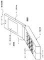
以下、本発明の携帯電話機の各実施形態について、図面を参照して説明する。図1は、本発明の第一実施形態にかかる携帯電話機の上部本体の開いた状態を説明するための概略斜視図を示している。
また、図2は、本発明の第一実施形態にかかる携帯電話機の上部本体の閉じた状態を説明するための概略斜視図を示している。
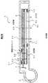
また、図3は、本発明の第一実施形態にかかる携帯電話機の上部本体の内部構造を説明するための、図2における上部本体のA−A線概略断面図を示している。
【0018】
「第一実施形態」
携帯電話機1は、図1及び図2に示すように、下部本体2と上部本体3とからなっており、下部本体2と上部本体3は、ヒンジ4を介して、回動自在に連結してある。
また、携帯電話機1は、下部本体2に、操作キーとしてのキーボタン21及びマイク22を配設してあり、また、無線部、制御部、記憶部等を内蔵した構成としてある。
【0019】
携帯電話機1は、図1に示すように、上部本体3の表面側に表面表示部31及びスピーカ33が設けてあり、この表面表示部31は、大型の表示画面としてあり、多くの情報を一画面に表示する。
また、携帯電話機1は、図2に示すように、上部本体3の裏面側に裏面表示部32が設けてあり、この裏面表示部32は、小型の表示画面としてあり、簡単な情報、たとえば、電話を着信したときの相手先の電話番号などを表示する。
【0020】
つまり、携帯電話機1は、利用者が上部本体3を開けなくても、着信した際、誰からの電話かを知ることができるので、使い勝手を向上させた構造としてある。
また、携帯電話機1は、利用者が普通に使用するときは、大型の表面表示部31が見やすい画像を表示し、かつ、携帯するときは、上部本体3を閉じることにより携帯性を損なうこともない。
【0021】
表面表示部31は、図3に示すように、透過型LCDとしてあり、フロントスクリーン51と、フロントLCD52と、フロント防塵クッション53と、導光板6と、フロント反射板54とからなっている。
また、裏面表示部32は、反射型LCDとしてあり、リアスクリーン55と、リアLCD56と、リア防塵クッション57と、導光板6と、リア反射板58とからなっている。
【0022】
このように、携帯電話機1は、表面表示部31と裏面表示部32が、導光板6を共用化しており、導光板6が、透過型のフロントLCD52と反射型のリアLCD56に光を照射している。したがって、携帯電話機1は、導光板6の共用化により、一個の導光板6を使用するだけですみ、部品費用や組立費用のコストダウンを図ることができる。
なお、携帯電話機1は、図示してないが、たとえば、反射型LCDの照明部を設けない構造とすることもでき、このようにすると、構造を単純化することができるので、部品費用や組立費用のコストダウンを図ることができる。
【0023】
また、携帯電話機1は、表面表示部31に透過型LCDを用い、かつ、裏面表示部32に反射型LCDを用いている。したがって、裏面表示部32を表示させる際、透過型LCDの表示に必要な光量より反射型LCDの表示に必要な光量が少なくてすむので、その分だけ電力の浪費を防ぐことができる。
【0024】
導光板6は、光を入光させるための光源としてLED7と、入光させた光を反射させるためのプリズム面61を具備している。
このように、光源としてLED7を使用することにより、光源の小型化及び発光効率の向上を図ることができる。
また、導光板6を表面表示部31と裏面表示部32に共用することにより、LED7の使用個数をも低減することができ、部品費及び組立費のコストダウンを図ることができる。
【0025】
また、携帯電話機1は、上部本体3の開閉を検知する開閉検知手段9を備えた構成としてある。
この開閉検知手段9は、下部本体2に固定された下部本体側電極91,上部本体3に固定され、上部本体3が閉じた状態のとき下部本体側電極91と電気的に接続する上部本体側閉用電極92,及び,上部本体3が開いた状態のとき下部本体側電極91と電気的に接続する上部本体側開用電極93とで構成してある。そして、開閉検知手段9は、制御部(図示せず)が、下部本体側電極91と、上部本体側閉用電極92又は上部本体側開用電極93との導通を検知することにより、上部本体3の開閉状態を検知する。なお、開閉検知手段9は、上記構造に限定するものではない。
【0026】
ここで、携帯電話機1は、上部本体3の開閉に応じてLED7の出力を調整する構成とするとよい。このようにすることにより、たとえば、図2に示すように、上部本体3が閉じたとき、すなわち、裏面表示部32しか見えなとき、LED7の光量を、小型の裏面表示部32を視認するのに必要な最小の光量に抑えることができる。また、図1に示すように、上部本体3が開いたときは、大型の表面表示部31を視認できるだけの光量を出力するように制御される。
なお、その他の構造は、上記従来例における携帯電話機と同様としてある。
【0027】
次に、上記携帯電話機1の動作について説明する。
携帯電話機1は、利用者が上部本体3を開くと、開閉検知手段9が上部本体3の開いた状態(本実施形態では、約90度以上開くと開いた状態として検知する。)を検知し、LED7が表面表示部31を視認できるだけの光量を出力する。そして、LED7から照射された光は、導光板6を通ってプリズム面61により反射され、透過型のフロントLCD52を通って出てくる。したがって、表面表示部31は、透過型LCDの画像を表示することができる。
【0028】
また、携帯電話機1は、利用者が上部本体3を閉めると、開閉検知手段9が上部本体3の閉まった状態(本実施形態では、ほぼ完全に閉められたとき、閉められた状態として検知する。)を検知し、LED7が裏面表示部32を視認するのに必要な最小の光量を出力する。
そして、LED7から照射された光は、導光板6を通ってプリズム面61により反射され、反射型のリアLCD56を一旦通過して、リア反射板58で反射されて再度リアLCD56を通過して出てくる。したがって、裏面表示部32は、反射型LCDの画像を表示することができる。
【0029】
つまり、携帯電話機1は、開閉検知手段9により上部本体3の開閉状態を自動的に検出し、たとえば、図2に示すように、上部本体3が閉じた状態のときは、裏面表示部32しか見えないため、LED7の光量を必要最小限に抑え、また、図1に示すように、上部本体3が開いた状態のときは、大型の表面表示部31を視認するために必要な光量を出力する。
【0030】
このように、本実施形態の携帯電話機1は、二組必要とされていた導光板6やLED7等の部品を共通化することができ、表示部31,32に関する部品点数を削減することにより、部品費用や組立費用のコストダウンを図ることができる。
また、携帯電話機1は、導光板6やLED7等の部品点数を削減することにより、小型化及び軽量化を図ることができる。
【0031】
また、本発明の携帯電話機は、上記構造に限定するものではなく、様々な実施形態を有するものである。
次に、本発明の携帯電話機における第二実施形態について図面を参照して説明する。
【0032】
「第二実施形態」
図4は、本発明の第二実施形態にかかる携帯電話機の上部本体の内部構造を説明するための、図2における上部本体のA−A線概略断面図を示している。
同図において、本応用例の携帯電話機は、上述したフロントLCD52とリアLCD56の代りに一つのLCD81を備え、すなわち、フロントLCD52とリアLCD56を一つのLCD81で共用化した構成としてある。
【0033】
ここで、LCD81は、裏面表示部32に対応する部分の表面側に反射板82を具備しており、裏面表示部32は、反射型LCDとなっている。
また、LCD81は、表面表示部31に対応する部分の裏面側に反射板83を具備しており、表面表示部31は、透過型LCDとなっている。
なお、その他の構造及び作用は、上記第一実施形態の携帯電話機1と同様としてある。
【0034】
このように、第二実施形態の携帯電話機は、LCD81を共用化することにより、LCDの使用個数を削減できるとともに、その他関連部品、たとえば、導光板6とLCD81の間に配設されたフロント防塵クッション53側のリア防塵クッション57の削減が可能であり、更なる原価低減や小型化を行うことができる。
【0035】
【発明の効果】
以上説明したように、本発明における携帯電話機によれば、一つの導光板で反射型LCDと透過型LCDを照光し、上部本体の表面側及び裏面側の両面において、表面表示部及び裏面表示部に画像を表示させることができる。
したがって、携帯電話機は、表示部に関連する部品、すなわち、導光板やLCDなどを共用化することができ、部品費及び組立費のコストダウンを図り、かつ、携帯電話機の小型化・軽量化を図ることができる。
【0036】
また、本発明における携帯電話機は、上部本体のいずれか一方の面の表示部に透過型LCDを用い、かつ、もう片方の面の表示部に反射型LCDを用いているので、透過型LCDの表示に必要な光量より反射型LCDの表示に必要な光量が少なくてすむぶんだけ電力の浪費を防ぐことができる。
【図面の簡単な説明】
【図1】図1は、本発明の第一実施形態にかかる携帯電話機の上部本体の開いた状態を説明するための概略斜視図を示している。
【図2】図2は、本発明の第一実施形態にかかる携帯電話機の上部本体の閉じた状態を説明するための概略斜視図を示している。
【図3】図3は、本発明の第一実施形態にかかる携帯電話機の上部本体の内部構造を説明するための、図2における上部本体のA−A線概略断面図を示している。
【図4】図4は、本発明の第二実施形態にかかる携帯電話機の上部本体の内部構造を説明するための、図2における上部本体のA−A線概略断面図を示している。
【図5】図5は、従来例における携帯電話機の上部本体を説明するための概略断面図を示している。
【符号の説明】
1 携帯電話機
2 下部本体
3 上部本体
4 ヒンジ
6,106,116 導光板
7,107,117 LED
9 開閉検知手段
21 キーボタン
22 マイク
31,131 表面表示部
32,132 裏面表示部
33 スピーカ
51 フロントスクリーン
52,152 フロントLCD
53,153 フロント防塵クッション
54 フロント反射板
55 リアスクリーン
56,156 リアLCD
57,157 リア防塵クッション
58 リア反射板
61 プリズム面
81 LCD
82,83 反射板
91 下部本体側電極
92 上部本体側閉用電極
93 上部本体側開用電極
100 上部本体[0001]
BACKGROUND OF THE INVENTION
The present invention relates to a mobile phone, and more particularly, to a foldable mobile phone having a display unit on both sides of an upper body to be folded.
[0002]
[Prior art]
In recent years, mobile phones have multi-functions including a mail function and an image display function.
For this reason, the mobile phone needs a large display unit so that more information can be displayed. In addition, even if the display portion is enlarged, it is required that the portability as a mobile phone is not impaired.
[0003]
As one solution for satisfying these conflicting demands, a cellular phone constituted by an upper body and a lower body that are foldably connected has been developed and commercialized.
This mobile phone has a large display portion on the surface side of the upper main body, and has a structure that does not impair portability by folding the upper main body to the lower main body side when being carried.
[0004]
By the way, the foldable mobile phone cannot see the display part when the upper body is folded. Therefore, for example, when you want to check the other party's phone number when you receive a call and check who is calling, or check the display without operating the key buttons, It was necessary to open the display part to expose the display part, and the handling was sometimes troublesome.
[0005]
For this reason, in Japanese Patent Application Laid-Open No. 2001-186227, a small display unit is provided on the back surface (the surface exposed when folded) so that simple information can be seen even when the upper body is folded. Proposed portable electronic devices have been proposed.
[0006]
(Conventional example)
Next, a mobile phone provided with display units on both sides of the above-described upper body will be described with reference to the drawings.
FIG. 5 is a schematic cross-sectional view for explaining an upper main body of a mobile phone according to a conventional example.
In the figure, reference numeral 100 denotes an upper body of a mobile phone according to a conventional example. A
[0007]
The surface display unit 131 uses a transmissive LCD, and includes a
In addition, the back surface display unit 132 uses a transmissive LCD, and includes a rear screen 55, a
[0008]
[Problems to be solved by the invention]
However, the conventional mobile phone has a structure in which the
[0009]
Further, this mobile phone is provided with
[0010]
The present invention has been made to solve the above-described problems, and provides a mobile phone capable of reducing the cost of parts and assembly and reducing the size by reducing the number of parts related to the display unit. With the goal.
[0011]
[Means for Solving the Problems]
In order to achieve the above object, a mobile phone of the present invention is a mobile phone in which a lower body provided with operation keys, a control device, and the like, and an upper body provided with display portions on both sides are foldably connected, The light guide plate of the display unit on the front surface side and the light guide plate of the display unit on the back surface side in the upper main body are shared, and atransmissive LCD is used for the display portion on either the front surface or the back surface of the upper main body. In addition, a reflective LCD is used for the display portion on the other side.
[0012]
By doing in this way, the number of parts of a light-guide plate can be reduced and the cost of parts cost and assembly cost can be reduced. In addition, since the structure of the reflective LCD can be simplified, it is possible to reduce the cost of parts and assembly.
[0013]
In themobile phone of the present invention, the transmissive LCD and the reflective LCD share the LCD.
By doing so, the number of parts of the LCD can be reduced, and the cost of parts and assembly can be reduced.
[0014]
Themobile phone according to the present invention includes an open / close detecting means for detecting a relative position of the upper main body to the lower main body.
By doing in this way, according to the open / closed state of the upper main body, it can be displayed on the display unit on either one of the surfaces, so that wasteful use of power can be prevented.
[0015]
In themobile phone of the present invention, the light amount of the light guide plate is changed according to the open / close state of the upper body detected by the open / close detecting means.
In this way, when the display unit to be displayed is a reflective LCD, the amount of light can be reduced, so that waste of power can be prevented.
[0016]
In themobile phone of the present invention, the light source of the light guide plate is an LED.
By doing so, it is possible to reduce the size of the light source and improve the light emission efficiency.
[0017]
DETAILED DESCRIPTION OF THE INVENTION
Hereinafter, embodiments of a mobile phone according to the present invention will be described with reference to the drawings. FIG. 1: has shown the schematic perspective view for demonstrating the open state of the upper main body of the mobile telephone concerning 1st Embodiment of this invention.
FIG. 2 is a schematic perspective view for explaining a closed state of the upper main body of the mobile phone according to the first embodiment of the present invention.
FIG. 3 is a schematic cross-sectional view taken along line AA of the upper body in FIG. 2 for explaining the internal structure of the upper body of the mobile phone according to the first embodiment of the present invention.
[0018]
"First embodiment"
As shown in FIGS. 1 and 2, the
In addition, the
[0019]
As shown in FIG. 1, the
Further, as shown in FIG. 2, the
[0020]
That is, the
In addition, when the user normally uses the
[0021]
As shown in FIG. 3, the surface display unit 31 is a transmissive LCD, and includes a
The back
[0022]
Thus, in the
Although not shown, the
[0023]
In addition, the
[0024]
The
Thus, by using the
Further, by sharing the
[0025]
Further, the
The open / close detection means 9 is fixed to the lower main body side electrode 91 fixed to the lower
[0026]
Here, the
The other structure is the same as that of the cellular phone in the conventional example.
[0027]
Next, the operation of the
When the user opens the
[0028]
In addition, when the user closes the
The light emitted from the
[0029]
That is, the
[0030]
As described above, the
Further, the
[0031]
Further, the mobile phone of the present invention is not limited to the above structure, and has various embodiments.
Next, a second embodiment of the mobile phone according to the present invention will be described with reference to the drawings.
[0032]
"Second embodiment"
FIG. 4 is a schematic cross-sectional view taken along line AA of the upper body in FIG. 2 for explaining the internal structure of the upper body of the mobile phone according to the second embodiment of the present invention.
In the figure, the cellular phone of this application example includes a
[0033]
Here, the
The
Other structures and operations are the same as those of the
[0034]
As described above, in the mobile phone according to the second embodiment, the number of LCDs used can be reduced by sharing the
[0035]
【The invention's effect】
As described above, according to themobile phone of the present invention, the reflective LCD and the transmissive LCD are illuminated by one light guide plate, and the front surface display unit and the rear surface display unit are provided on both the front side and the back side of the upper body. An image can be displayed on the screen.
Therefore, the mobile phone can share components related to the display unit, that is, the light guide plate and the LCD, reduce the cost of parts and assembly, and reduce the size and weight of the mobile phone. Can be planned.
[0036]
In addition, since the mobile phone according to the present invention uses a transmissive LCD for the display part on one side of the upper body and a reflective LCD for the display part on the other side, Since the amount of light required for display on the reflective LCD is less than the amount of light required for display, it is possible to prevent waste of power.
[Brief description of the drawings]
FIG. 1 is a schematic perspective view for explaining an open state of an upper body of a mobile phone according to a first embodiment of the present invention.
FIG. 2 is a schematic perspective view for explaining a closed state of the upper main body of the mobile phone according to the first embodiment of the present invention.
FIG. 3 is a schematic cross-sectional view taken along line AA of the upper body in FIG. 2 for explaining the internal structure of the upper body of the mobile phone according to the first embodiment of the present invention.
FIG. 4 is a schematic cross-sectional view taken along line AA of the upper body in FIG. 2 for explaining the internal structure of the upper body of the mobile phone according to the second embodiment of the present invention.
FIG. 5 is a schematic cross-sectional view for explaining an upper main body of a mobile phone in a conventional example.
[Explanation of symbols]
1
9 Opening / closing detection means 21
53,153 Front dustproof cushion 54 Front reflector 55 Rear screen 56,156 Rear LCD
57,157 Rear dustproof cushion 58 Rear reflector 61
82, 83 Reflector 91 Lower body side electrode 92 Upper body side closing electrode 93 Upper body side opening electrode 100 Upper body
Claims (5)
Translated fromJapanese前記上部本体における表面側の表示部の導光板と裏面側の表示部の導光板を共用化し、
さらに、前記上部本体の表面又は裏面における、いずれか一方の面の表示部に透過型LCDを用い、かつ、もう片方の面の表示部に反射型LCDを用いたことを特徴とする携帯電話機。A mobile phone in which a lower body provided with operation keys, a control device, etc., and an upper body provided with display portions on both sides are connected in a foldable manner,
Sharing the light guide plate of the display unit on the front side and the light guide plate of the display unit on the back side in the upper body,
Furthermore, a mobile phone characterized in that atransmissive LCD is used for the display portion on either side of the front or back surface of the upper body, and a reflective LCD is used for the display portion on the other side .
Priority Applications (1)
| Application Number | Priority Date | Filing Date | Title |
|---|---|---|---|
| JP2001381035AJP3683212B2 (en) | 2001-12-14 | 2001-12-14 | Mobile phone |
Applications Claiming Priority (1)
| Application Number | Priority Date | Filing Date | Title |
|---|---|---|---|
| JP2001381035AJP3683212B2 (en) | 2001-12-14 | 2001-12-14 | Mobile phone |
Publications (2)
| Publication Number | Publication Date |
|---|---|
| JP2003188959A JP2003188959A (en) | 2003-07-04 |
| JP3683212B2true JP3683212B2 (en) | 2005-08-17 |
Family
ID=27591847
Family Applications (1)
| Application Number | Title | Priority Date | Filing Date |
|---|---|---|---|
| JP2001381035AExpired - Fee RelatedJP3683212B2 (en) | 2001-12-14 | 2001-12-14 | Mobile phone |
Country Status (1)
| Country | Link |
|---|---|
| JP (1) | JP3683212B2 (en) |
Families Citing this family (33)
| Publication number | Priority date | Publication date | Assignee | Title |
|---|---|---|---|---|
| TWI289708B (en) | 2002-12-25 | 2007-11-11 | Qualcomm Mems Technologies Inc | Optical interference type color display |
| US7342705B2 (en) | 2004-02-03 | 2008-03-11 | Idc, Llc | Spatial light modulator with integrated optical compensation structure |
| US7706050B2 (en) | 2004-03-05 | 2010-04-27 | Qualcomm Mems Technologies, Inc. | Integrated modulator illumination |
| US7355780B2 (en) | 2004-09-27 | 2008-04-08 | Idc, Llc | System and method of illuminating interferometric modulators using backlighting |
| US7750886B2 (en)* | 2004-09-27 | 2010-07-06 | Qualcomm Mems Technologies, Inc. | Methods and devices for lighting displays |
| US7349141B2 (en) | 2004-09-27 | 2008-03-25 | Idc, Llc | Method and post structures for interferometric modulation |
| US7813026B2 (en) | 2004-09-27 | 2010-10-12 | Qualcomm Mems Technologies, Inc. | System and method of reducing color shift in a display |
| US7561323B2 (en) | 2004-09-27 | 2009-07-14 | Idc, Llc | Optical films for directing light towards active areas of displays |
| TWI386744B (en) | 2004-12-14 | 2013-02-21 | Samsung Display Co Ltd | Thin film transistor panel and liquid crystal display using the same |
| US7603001B2 (en) | 2006-02-17 | 2009-10-13 | Qualcomm Mems Technologies, Inc. | Method and apparatus for providing back-lighting in an interferometric modulator display device |
| US7766498B2 (en) | 2006-06-21 | 2010-08-03 | Qualcomm Mems Technologies, Inc. | Linear solid state illuminator |
| US7845841B2 (en) | 2006-08-28 | 2010-12-07 | Qualcomm Mems Technologies, Inc. | Angle sweeping holographic illuminator |
| US7855827B2 (en) | 2006-10-06 | 2010-12-21 | Qualcomm Mems Technologies, Inc. | Internal optical isolation structure for integrated front or back lighting |
| EP1943551A2 (en) | 2006-10-06 | 2008-07-16 | Qualcomm Mems Technologies, Inc. | Light guide |
| EP1943555B1 (en) | 2006-10-06 | 2012-05-02 | QUALCOMM MEMS Technologies, Inc. | Optical loss structure integrated in an illumination apparatus of a display |
| EP2069838A2 (en) | 2006-10-06 | 2009-06-17 | Qualcomm Mems Technologies, Inc. | Illumination device with built-in light coupler |
| US8107155B2 (en) | 2006-10-06 | 2012-01-31 | Qualcomm Mems Technologies, Inc. | System and method for reducing visual artifacts in displays |
| EP1958010A2 (en) | 2006-10-10 | 2008-08-20 | Qualcomm Mems Technologies, Inc | Display device with diffractive optics |
| US7864395B2 (en) | 2006-10-27 | 2011-01-04 | Qualcomm Mems Technologies, Inc. | Light guide including optical scattering elements and a method of manufacture |
| US7777954B2 (en) | 2007-01-30 | 2010-08-17 | Qualcomm Mems Technologies, Inc. | Systems and methods of providing a light guiding layer |
| US7733439B2 (en) | 2007-04-30 | 2010-06-08 | Qualcomm Mems Technologies, Inc. | Dual film light guide for illuminating displays |
| US8941631B2 (en) | 2007-11-16 | 2015-01-27 | Qualcomm Mems Technologies, Inc. | Simultaneous light collection and illumination on an active display |
| US8068710B2 (en) | 2007-12-07 | 2011-11-29 | Qualcomm Mems Technologies, Inc. | Decoupled holographic film and diffuser |
| US7949213B2 (en) | 2007-12-07 | 2011-05-24 | Qualcomm Mems Technologies, Inc. | Light illumination of displays with front light guide and coupling elements |
| WO2009102733A2 (en) | 2008-02-12 | 2009-08-20 | Qualcomm Mems Technologies, Inc. | Integrated front light diffuser for reflective displays |
| WO2009102731A2 (en) | 2008-02-12 | 2009-08-20 | Qualcomm Mems Technologies, Inc. | Devices and methods for enhancing brightness of displays using angle conversion layers |
| US8654061B2 (en) | 2008-02-12 | 2014-02-18 | Qualcomm Mems Technologies, Inc. | Integrated front light solution |
| WO2009129264A1 (en) | 2008-04-15 | 2009-10-22 | Qualcomm Mems Technologies, Inc. | Light with bi-directional propagation |
| US8118468B2 (en) | 2008-05-16 | 2012-02-21 | Qualcomm Mems Technologies, Inc. | Illumination apparatus and methods |
| CN102047155B (en) | 2008-05-28 | 2013-04-03 | 高通Mems科技公司 | Light guide panel with light turning microstructure, its manufacturing method and display device |
| US8172417B2 (en) | 2009-03-06 | 2012-05-08 | Qualcomm Mems Technologies, Inc. | Shaped frontlight reflector for use with display |
| CN102449512A (en) | 2009-05-29 | 2012-05-09 | 高通Mems科技公司 | Illumination devices and methods of fabrication thereof |
| US8902484B2 (en) | 2010-12-15 | 2014-12-02 | Qualcomm Mems Technologies, Inc. | Holographic brightness enhancement film |
- 2001
- 2001-12-14JPJP2001381035Apatent/JP3683212B2/ennot_activeExpired - Fee Related
Also Published As
| Publication number | Publication date |
|---|---|
| JP2003188959A (en) | 2003-07-04 |
Similar Documents
| Publication | Publication Date | Title |
|---|---|---|
| JP3683212B2 (en) | Mobile phone | |
| JP3977169B2 (en) | Mobile terminal device | |
| AU761041B2 (en) | Portable radio communication apparatus | |
| CN100492924C (en) | Portable terminal device with holographic screen as display unit | |
| EP1887764B1 (en) | Portable communication terminal having display unit using panel-type waveguide | |
| US7184796B2 (en) | Personal communication device having a built in projection display | |
| US5901223A (en) | Wireless telephone with extension having peripheral devices provided thereon | |
| JPWO2004027504A1 (en) | Liquid crystal display device and mobile phone device using liquid crystal display device | |
| WO2002103442A1 (en) | Electronic appliance | |
| JPH0774691A (en) | Portable telephone set with folding mechanism | |
| CN101419359A (en) | Liquid crystal display apparatus and portable phone incorporating the same | |
| JP2005070603A (en) | Double-sided liquid crystal display and portable wireless telephone | |
| JP2001313702A (en) | Portable communication terminal | |
| US7221559B1 (en) | Multipurpose bumper system for a data processing apparatus | |
| JP3645838B2 (en) | Mobile phone | |
| JP2004040464A (en) | Mobile phone | |
| KR100841187B1 (en) | Liquid crystal display and mobile phone provided with the same | |
| KR100818143B1 (en) | Two-speed mobile phone | |
| CN101572733B (en) | Mobile terminal device | |
| KR101612790B1 (en) | Portable terminal | |
| EP1480417B1 (en) | Clamshell-type mobile terminal with flexible display | |
| KR20020090539A (en) | Liquid crystal display apparatus for dual folder phone | |
| JP2852259B2 (en) | Mobile phone | |
| JP2003319037A (en) | Mobile phone | |
| JP2005121998A (en) | Liquid crystal display device and portable device |
Legal Events
| Date | Code | Title | Description |
|---|---|---|---|
| A977 | Report on retrieval | Free format text:JAPANESE INTERMEDIATE CODE: A971007 Effective date:20050201 | |
| A131 | Notification of reasons for refusal | Free format text:JAPANESE INTERMEDIATE CODE: A131 Effective date:20050208 | |
| A521 | Written amendment | Free format text:JAPANESE INTERMEDIATE CODE: A523 Effective date:20050407 | |
| TRDD | Decision of grant or rejection written | ||
| A01 | Written decision to grant a patent or to grant a registration (utility model) | Free format text:JAPANESE INTERMEDIATE CODE: A01 Effective date:20050510 | |
| A61 | First payment of annual fees (during grant procedure) | Free format text:JAPANESE INTERMEDIATE CODE: A61 Effective date:20050524 | |
| R150 | Certificate of patent or registration of utility model | Free format text:JAPANESE INTERMEDIATE CODE: R150 | |
| LAPS | Cancellation because of no payment of annual fees |