JP3680050B2 - Medical manipulator and control method thereof - Google Patents
Medical manipulator and control method thereofDownload PDFInfo
- Publication number
- JP3680050B2 JP3680050B2JP2002271947AJP2002271947AJP3680050B2JP 3680050 B2JP3680050 B2JP 3680050B2JP 2002271947 AJP2002271947 AJP 2002271947AJP 2002271947 AJP2002271947 AJP 2002271947AJP 3680050 B2JP3680050 B2JP 3680050B2
- Authority
- JP
- Japan
- Prior art keywords
- unit
- power transmission
- command
- origin
- posture
- Prior art date
- Legal status (The legal status is an assumption and is not a legal conclusion. Google has not performed a legal analysis and makes no representation as to the accuracy of the status listed.)
- Expired - Lifetime
Links
Images


Classifications
- A—HUMAN NECESSITIES
- A61—MEDICAL OR VETERINARY SCIENCE; HYGIENE
- A61B—DIAGNOSIS; SURGERY; IDENTIFICATION
- A61B17/00—Surgical instruments, devices or methods
- A61B17/00234—Surgical instruments, devices or methods for minimally invasive surgery
- A—HUMAN NECESSITIES
- A61—MEDICAL OR VETERINARY SCIENCE; HYGIENE
- A61B—DIAGNOSIS; SURGERY; IDENTIFICATION
- A61B34/00—Computer-aided surgery; Manipulators or robots specially adapted for use in surgery
- A61B34/70—Manipulators specially adapted for use in surgery
- A—HUMAN NECESSITIES
- A61—MEDICAL OR VETERINARY SCIENCE; HYGIENE
- A61B—DIAGNOSIS; SURGERY; IDENTIFICATION
- A61B34/00—Computer-aided surgery; Manipulators or robots specially adapted for use in surgery
- A61B34/70—Manipulators specially adapted for use in surgery
- A61B34/72—Micromanipulators
- A—HUMAN NECESSITIES
- A61—MEDICAL OR VETERINARY SCIENCE; HYGIENE
- A61B—DIAGNOSIS; SURGERY; IDENTIFICATION
- A61B90/00—Instruments, implements or accessories specially adapted for surgery or diagnosis and not covered by any of the groups A61B1/00 - A61B50/00, e.g. for luxation treatment or for protecting wound edges
- A61B90/50—Supports for surgical instruments, e.g. articulated arms
- A—HUMAN NECESSITIES
- A61—MEDICAL OR VETERINARY SCIENCE; HYGIENE
- A61B—DIAGNOSIS; SURGERY; IDENTIFICATION
- A61B17/00—Surgical instruments, devices or methods
- A61B2017/00017—Electrical control of surgical instruments
- A—HUMAN NECESSITIES
- A61—MEDICAL OR VETERINARY SCIENCE; HYGIENE
- A61B—DIAGNOSIS; SURGERY; IDENTIFICATION
- A61B17/00—Surgical instruments, devices or methods
- A61B2017/00477—Coupling
Landscapes
- Health & Medical Sciences (AREA)
- Surgery (AREA)
- Life Sciences & Earth Sciences (AREA)
- Engineering & Computer Science (AREA)
- Heart & Thoracic Surgery (AREA)
- Animal Behavior & Ethology (AREA)
- Veterinary Medicine (AREA)
- Biomedical Technology (AREA)
- Nuclear Medicine, Radiotherapy & Molecular Imaging (AREA)
- Medical Informatics (AREA)
- Molecular Biology (AREA)
- Public Health (AREA)
- General Health & Medical Sciences (AREA)
- Robotics (AREA)
- Pathology (AREA)
- Oral & Maxillofacial Surgery (AREA)
- Manipulator (AREA)
- Surgical Instruments (AREA)
Description
Translated fromJapanese【0001】
【発明の属する技術分野】
本発明は、医療用マニピュレータに係り、特に、機構が単純化されると共に操作性と安全性に優れる医療用マニピュレータに関する。
【0002】
【従来の技術】
従来、胆嚢摘出手術などの腹腔鏡下手術においては、図13に示すように、患者150の腹部に小さな穴151、152、153をいくつかあけ、それらにトラカール154を取り付け、トラカール154を介して、それらの孔に内視鏡161、鉗子171、172などを挿入し、術者(通常、外科医)160が内視鏡161の映像をモニタ162で見ながら手術を行っている。このような手術方法は、開腹を必要としないため、患者への負担が少なく、術後の回復や退院までの日数が大幅に低減される。このため、このような手術方法は、適用分野の拡大が期待されている。
【0003】
そのような背景のもと、マスタスレーブマニピュレータなどの遠隔操作型ロボット技術を医療分野へ応用する研究が行われ、一部臨床応用されている(http://www.computermotion.com, http://www.intuitivesurgical.com)。遠隔操作型ロボット技術は、術者が操作するマスタアームと実際に術部に操作を施すスレーブアームとが完全に分離したロボットシステムであり、マスタアームの指令値が電気信号としてスレーブアームに伝わるものである。したがって、通常、マスタアームとスレーブアームとはそれぞれ6自由度以上の関節数を有しており、それぞれの自由度に対応してコントローラが設けられており、電気的に多数の制御系、部品、配線を有する複雑なシステムとなっている。
【0004】
このような問題点を解決するために、発明者らは、図14に示すような、従来の鉗子にロボット技術を取り入れた医療用マニピュレータ(ロボット鉗子)を提案している(特許文献1).姿勢操作部23と処置操作部24とを有する操作指令部20と、一端側が操作指令部10に接続された連結部30と、連結部30の他端側に接続され、処置部14と処置部14を2自由度以上に姿勢変更可能に支持する支持部15、16とを有する作業部10と、姿勢操作部23からの操作指令を支持部15、16に送って処置部14の姿勢を変更させるとともに、処置操作部24からの操作指令を処置部14に送って処置部14を動作させる制御部(図示せず)と、を備えた医療用マニピュレータである。
【0005】
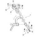
さらに、発明者らは、縫合結紮作業に適した自由度配置として、図15に示すような医療用マニピュレータも提案している(特許文献2)。医療用マニピュレータは、作業部10と、操作指令部20と、両端が作業部10と操作指令部20とに接続された連結部30とを備えている。作業部10は、連結部30の中心軸方向31に対して直交する第1の回転軸11と第1の回転軸11に対して直交する第2の回転軸12からなる支持部と、術部に処置を施す処置部とを有する。処置部の把持動作13を行うグリッパ14の中心軸方向が、第2の回転軸12の軸方向と概ね平行に配置されている。言いかえれば、作業部10は、グリッパ14を2自由度で姿勢変更に可能に支持する支持部としてのピッチ軸関節支持部15およびロール軸関節支持部16とを有している。操作指令部20は、連結部30の中心軸方向31に対して直交する第3の回転軸21と第3の回転軸21に対して直交する第4の回転軸22からなる姿勢操作部23と、操作者が把持して操作する処置操作部24とを有している。操作者が把持して処置操作部24を操作する際の操作者の手首の回転方向は第4の回転軸22の軸方向と概ね平行である。術部に処置を施す処置部14の把持動作13は、処置操作部24の把持動作25により行う。
【0006】
上述のようなロボット鉗子は,遠隔操作型マスタスレーブマニピュレータと異なり、操作部(マスタ部)と鉗子先端部ハンド(スレーブ部)とを連結して一体化させ、従来の鉗子の利点である術者が行った方が簡単で確実な大きく素早い操作と,マニピュレータの利点である微細な作業や難しい角度からの操作との両方の操作を可能としたものである。先端部に曲げ・回転などの関節を備えているため、自由自在にハンドの姿勢を動かすことができ,これまでの鉗子では難しかったいろいろな方向からの縫合作業や結紮作業が容易になり、また、右手はロボット鉗子、左手は従来の鉗子という具合に、従来の手術機器と一緒に使うことができ、さらに、システムが簡単でコンパクトなため、低コストで導入できるというメリットがある。
【0007】
【特許文献1】
特開P2000−350735号公報
【特許文献2】
特開P2002−102248号公報
【0008】
【発明が解決しようとする課題】
医療用ロボットに限らず医療機器、特に手術機器は、滅菌洗浄作業を施さなければ、実際の手術に使用することはできない。
通常、医療用ロボットや医療機器、手術機器の処置部(作業部)は、患者の血液、組織などが付着するため、洗浄および滅菌する必要がある。大きな装置の場合は、少なくとも直接患者と接触する処置部(作業部)は、本体あるいは操作司令部から取り外し洗浄および滅菌できる構成となっている。このため、医療用ロボットや医療機器、手術機器の処置部(作業部)の操作指令部からの着脱は必須とも言える。そして、滅菌等のために操作指令部はずされた処置部(作業部)は、再び操作指令部に結合される際に、所定の位置姿勢関係が回復される必要がある。
【0009】
一方、一般的にロボットは、電源投入時にリセット動作、すなわち原点復帰動作が必要である。原点復帰動作とは、ロボットの関節を所定のシーケンスに従い動作させることで関節に配置された原点センサによって原点位置を検出し間節の角度位置を原点位置にし、モータ軸に配置されたインクリメンタルエンコーダをリセットし原点位置とする動作である。医療用ロボットによる手術を行うために手術中に原点復帰動作することは、大変面倒であり、手術の緊迫した状況を考慮すると、出来る限り避けたい動作である。そこで、電源投入後すぐ使える、すなわち上述のような原点復帰動作を不要とする医療用ロボットが望まれている。
【0010】
さらに、発明者らが提案している前述の医療用マニピュレータは、マスタ部とスレーブ部とが一体型に構成されている。そして、術者が直接医療用マニピュレータ本体を操作することになり医療用マニピュレータ本体の自重を支持しなければならない。このため、医療用マニピュレータ本体の小型軽量化を図ることが操作性を向上させること上の最大の課題となっている。従って、原点センサを関節部または他の部分に配置することはスペース的にも重量的にも非常に困難であり好ましくない。仮に原点センサを配置できたとしても、配線などが非常に増えケーブルの重量が増し、操作性を大幅に低下させることになる。
【0011】
また、アブソリュートエンコーダを搭載することで原点復帰動作を必要としなくとも常に絶対位置を把握可能なロボットを構成することも可能であるが、インクリメンタルエンコーダを搭載する場合より大きくまた配線なども多く、発明者らが提案している上述の医療用マニピュレータには適さない。
【0012】
そこで、本発明の目的は、上記従来技術の有する問題を解消し、作業部と駆動部とを結合分離が自在であって作業部の洗浄滅菌等を可能とし、駆動部の所定の結合位置に作業部を結合可能であり手術時の原点復帰動作を不要にした小型軽量で操作性に優れた医療用マニピュレータを提供することである。
【0013】
【課題を解決するための手段】
そこで、本発明の医療用マニピュレータは、作業を行う作業部と、操作指令を生成する操作部と、前記操作部の操作指令に基づき前記作業部を駆動するための駆動部と、前記駆動部の駆動力を前記作業部に伝達するための動力伝達機構と、前記操作部の操作指令に基づき前記駆動部を制御する制御部とを備え、前記動力伝達機構は、前記駆動部側にある第1動力伝達部と、前記第1動力伝達部と前記駆動部との間に設けられた減速機と、前記作業部側にあり前記第1動力伝達部と結合分離自在である第2動力伝達部とを有することを特徴とする。
【0014】
また、前記制御部は、正常動作の終了時には前記第1動力伝達部の結合位置を所定結合位置に設定することを特徴とする。
【0015】
また、前記第1動力伝達部と前記第2動力伝達部とを分離した状態で前記第1動力伝達部に結合分離自在であり、前記第1動力伝達部に結合し前記第1動力伝達部の所定結合位置を検出可能な原点検出手段を備えることを特徴とする。
【0016】
また、前記制御部は、電源が投入されると初期化され、前記制御部が初期化された後に待機状態となり、前記待機状態において定期的に操作者の指令を監視し、前記待機状態において操作開始指令が指令された場合、操作部の姿勢に作業部の姿勢が追従するように制御するとともに、少なくとも操作停止命令と原点復帰指令の2つの指令を監視し、前記操作停止指令を検知した場合、指令が検知された際の姿勢を維持した前記待機状態となり、前記原点復帰指令を検知した場合、初期化された際の姿勢になるように駆動部を制御する原点復帰動作を行い、初期化された際の姿勢となった後にはその姿勢を維持した前記待機状態となり、前記待機状態においてシステム終了指令を検知した場合、前記待機状態の直前の動作が前記原点復帰動作であるかどうかを判断し、前記原点復帰動作であると判断した場合、正常動作を可能と判断し、原点復帰動作でないと判断した場合は、システム終了指令は誤りであったと判断することを特徴とする。
また、本発明の医療用マニピュレータの制御方法は、作業を行う作業部と、操作指令を生成する操作部と、前記操作部の操作指令に基づき前記作業部を駆動するための駆動部と、前記操作部の操作指令に基づき前記駆動部を制御する制御部とを有する医療用マニピュレータの制御方法であって、待機状態において定期的に操作者の指令を監視し、前記待機状態において操作開始指令が指令された場合、操作部の姿勢に作業部の姿勢が追従するように制御するとともに、少なくとも操作停止命令と原点復帰指令の2つの指令を監視し、前記操作停止指令を検知した場合、指令が検知された際の姿勢を維持した前記待機状態となり、前記原点復帰指令を検知した場合、電源が投入された際の姿勢になるように駆動部を制御する原点復帰動作を行い、電源が投入された際の姿勢となった後にはその姿勢を維持した前記待機状態となり、前記待機状態においてシステム終了指令を検知した場合、前記待機状態の直前の動作が前記原点復帰動作であるかどうかを判断し、前記原点復帰動作であると判断した場合、正常動作を可能と判断し、原点復帰動作でないと判断した場合は、システム終了指令は誤りであったと判断することを特徴とする。
【0017】
本発明によれば、第1動力伝達部と第2動力伝達部とは結合分離自在であり、第1動力伝達部は、第1動力伝達部と第2動力伝達部とを結合する場合に、第2動力伝達部の結合位置を結合前の第1動力伝達部の結合位置に追従させることが可能な大きさのバックドライブトルクを有するので、作業部の洗浄滅菌等を可能とし、アブソリュートエンコーダや原点センサ等を搭載しなくとも、これらを用いた場合の原点復帰動作と同様のことを実現でき、作業部と駆動部との結合分離の前後において、作業部の原点位置を常に確保することが可能になる。
【0018】
また、制御部は、正常動作の終了時には前記第1動力伝達部の結合位置を所定結合位置に設定するので、手術に医療用マニピュレータを用いる際には、電源投入後、面倒な原点復帰動作をすることなくすぐに使うことができ、これにより、手術の緊迫した状況での面倒な作業を回避することができるため手術の大幅な効率向上が可能となる。
【0019】
また、第1動力伝達部に結合分離自在の原点検出手段を設けたので、原点検出手段を常時に搭載することをせずとも、駆動部側の原点検出を可能にすることができ、正常動作終了時以外(非常終了時など)にも原点復帰動作が可能となる。
【0020】
【発明の実施の形態】
以下、図面を参照して本発明の実施の形態について説明する。
【0021】
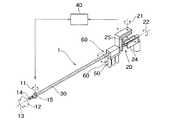
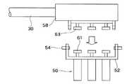
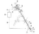
図1は、本発明の第1の実施の形態による医療用マニピュレータ1を示す概略構成図である。医療用マニピュレータ1は作業を行う作業部10と、作業部1を操作するための操作指令を生成する操作部20と、操作部20の操作指令に基づき作業部10を駆動するための駆動部50と、駆動部50の駆動力を作業部10へ伝達するための動力伝達機構60と、操作部20の操作指令に基づき作業部10に作業を行わせるように駆動部50を制御する制御部40とを備えている。作業部10と操作部20とは棒状の連結部30によって連結されている。作業部10は連結連結部30の一端側に配設され、操作部20と駆動部50は連結部30の他端側に近接して配置されている。駆動部50は3個のモータ等から構成されている。なお、自由度の数や自由度の配置については、図1に示す構成に限る必要はなく、種々の変形が可能である。
【0022】
動力伝達機構60は、連結部30を間にして作業部10と駆動部50との間に設けられている。動力伝達機構60は後述するように、第1動力伝達部61と第2動力伝達部63とを結合分離し、作業部10側と駆動部50側とが結合分離自在であるように構成されている。
【0023】
動力伝達機構60は、例えば、リンク、歯車、ワイヤ・プーリ、減速機、カップリングなど複数の動力伝達要素から構成されている。動力伝達機構60は、モータを備える駆動部50の動力を連結部30内に配設されたワイヤ・プーリ等を介して作業部10へ伝達する。動力伝達機構60は、駆動部50の動力を作業部10まで伝達することで作業部10に曲げ動作、回転動作、把持動作などの動作を行わせる。
【0024】
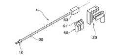
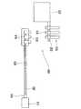
図2は、作業部10と駆動部50とを結合分離自在にする一形態を示し、作業部10及び連結部30と、駆動部50及び操作部20とに分離した状態の概略構成図である。なお、作業部10と駆動部50とを結合分離自在にする形態としては、図2に示す場合に限らず、図3に示すように、作業部10,連結部30及び操作部20とを一体的に駆動部50に結合分離するようにしてもよい。また、図4に示すように、図3に示す場合においてさらに操作部20を作業部10及び連結部30から分離し、作業部10及び連結部30と、操作部20と、駆動部50との三者の間で結合分離するようにしてもよい。以下では、作業部10と駆動部50とを結合分離自在にする形態として図2に示す場合を例にとり説明する。
【0025】
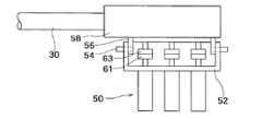
図2及び図7に示すように、動力伝達機構60は、駆動部50側には、カップリングからなる第1動力伝達部61と、第1動力伝達部61と駆動部50との間に配設された減速機からなる動力伝達要素62とを有する。また、動力伝達機構60は、作業部10には、カップリングからなる第2動力伝達部63と、第2動力伝達部63に連結されたプーリからなる動力伝達要素64と、動力伝達要素64に連結されたワイヤロープ、またはロッドリンク等からなる動力伝達要素65と、動力伝達要素65と作業部10との間に配設されたプーリ、歯車、リンク等からなる動力伝達要素66を有する。カップリングからなる第1動力伝達部61とカップリングからなる第2動力伝達部63とが結合分離されることによって、作業部10と駆動部50との間で動力の伝達・切断が可能となっている。なお、動力伝達機構60における動力伝達要素はどのような組合せであってもよい。
【0026】
図8及び図9に、医療用マニピュレータ1の作業部10と駆動部50の結合時(使用時)と分離時(洗浄時)の結合分離の態様を示す。3個の駆動モータからなる駆動部50と第1動力伝達部61は結合台52に取り付けられており、結合台52と相対する結合台56には第2動力伝達部63と動力伝達要素収容部56が取り付けられている。動力伝達要素収容部56は結合部30の端部に結合され、内部に動力伝達要素64等が収容されている。ラッチピン54により結合台52と結合台56とを互いに結合分離することにより、第1動力伝達部61と第2動力伝達部63との結合分離が図られる。このために、第1動力伝達部61と第2動力伝達部63とが分離した状態で互いに合わせ、その後に予め原点位置にある第1動力伝達部61の結合位置に第2動力伝達部63の結合位置を追従させるように第2動力伝達部63の結合位置を調整する。この調整が終えた段階でラッチピン54により結合台52と結合台56とを互いに結合することによって、医療用マニピュレータ1の原点位置が確保される。なお、第1動力伝達部61と第2動力伝達部63との結合分離の手法については、ラッチピン54や結合台52,54を使用するような場合に限らず、ねじを用いる場合等種々の態様が可能である。
【0027】
手術等の作業を終えた後に作業部10を洗浄消毒し、洗浄等の後に第1動力伝達部61と第2動力伝達部63とを再び結合することについて説明する。この場合、第1動力伝達部61と第2動力伝達部63とは分離されるが、第1動力伝達部61のカップリングの分離時の位置は保存されそのまま結合位置となるように、第1動力伝達部61は十分に大きなバックドライブトルクを有する。ここで、第1動力伝達部61のバックドライブトルクとは、通常のように駆動部50側から第1動力伝達部61の側に向かって動力を伝達するのとは逆に、第1動力伝達部61の側から駆動部50の側に向かって動力を伝達するのに要するトルクの大きさをいう。第1動力伝達部61のバックドライブトルクが十分に大きいとは、例えば、手作業で第1動力伝達部61のカップリングの結合位置を変えようしてしても変動できないほどに大きいことをいう。
【0028】
また、第1動力伝達部61は、医療用マニピュレータ1の正常動作の終了時には、制御部40によって所定結合位置(例えば原点位置)に設定されるように構成されている。従って、医療用マニピュレータ1が正常動作を終了し、作業部10と駆動部50との分離がなされる時点では、第1動力伝達部61の分離位置は原点位置(所定結合位置)にある。そして、上述したように、第1動力伝達部61のバックドライブトルクが十分に大きいので、結合時においても第1動力伝達部61は原点位置にある。
【0029】
一方、作業部10にある第2動力伝達部63は分離された状態で、第2動力伝達部63の側から作業部10の側に向かうドライブトルクは比較的に小さく、容易に手で動かしてドライブできる程度の大きさであるように構成されている。このため、分離された作業部10を洗浄等を行う際に、第2動力伝達部63のカップリングの分離時の位置は保存されるとは限らず他の位置へ動き得る。この場合、第2動力伝達部63の結合位置が分離時と異なる位置にあると、このままでは第1動力伝達部61と第2動力伝達部63とは分離時と同じ結合関係にはならない。これに対し、本実施の形態では、第1動力伝達部61のバックドライブトルクが十分に大きく、第2動力伝達部63の側から作業部10の側に向かうドライブトルクは比較的に小さいので、第1動力伝達部61と第2動力伝達部63とを結合する場合に、第1動力伝達部61と第2動力伝達部63とを合わせてまず結合し、次に第2動力伝達部63の結合位置を原点位置にある第1動力伝達部61の結合位置に追従させるようにすることができる。
【0030】
作業部10は直接患者体内に接し血液や組織が付着するため、手術後には、一旦駆動部50から取り外し、よく洗浄・滅菌する必要がある。特に、洗浄する際は、作業部10側の第2動力伝達部63や動力伝達要素64,65,66をドライブし、よく手動で動かして、第2動力伝達部63や動力伝達要素64,65,66の隙間に付着した血液や組織を洗い流す必要がある。従って、再び装着する際には、取り外した時の状態と多少異なった状態になっているのが普通である。しかしながら本実施の形態による医療用マニピュレータ1では、前述したように、第2動力伝達部63の結合位置を原点位置にある第1動力伝達部61の結合位置に追従させることができるので、第2動力伝達部63が分離した時の状態と多少異なった状態になっていたとしても、結合する時に第1動力伝達部61によって原点位置にドライブさせることになるため、分離時の状態を復元することが可能である。もし、第2動力伝達部63の側から作業部10の側に向かうドライブトルクが第1動力伝達部61のバックドライブトルクと同等あるいはより大きい場合には、第1動力伝達部61がバックドライブトルクされることになるため、分離時の状態を復元することは不可能である。
【0031】
従って、本発明による実施の形態による医療用マニピュレータ1では、作業部10と駆動部50を分離し、洗浄作業などで作業部10側の第2動力伝達部63が分離した時の状態と多少異なっていたとしても容易に分離時の状態を復元することができる。なお、滅菌作業は、洗浄・装着後に行ってもよい。
【0032】
このようにして、本実施の形態によれば、アブソリュートエンコーダや原点センサ等を搭載しなくとも、作業部10と駆動部50との結合分離の前後において、作業部10の原点位置を常に確保することが可能になる。そして、医療用マニピュレータ1の本体の小型軽量化を図り操作性を向上させることができる。
【0033】
次に、図5,図6、図10及び図11を参照して、本発明の第2の実施の形態について説明する。
【0034】
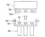
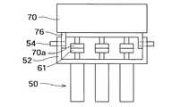
本実施の形態では、第1動力伝達部61の原点位置を検出可能な原点検出手段70が設けられている。原点検出手段70は、第1動力伝達部61と第2動力伝達部63とを分離した状態で第1動力伝達部61に結合分離自在に形成されている。原点検出手段70は第2動力伝達部63から分離された第1動力伝達部61に結合される。図10,図11に示すように、原点検出手段70は結合台76に取り付けられており、結合台76には原点検出手段70のカップリング70aが設けられている。カップリング70aを第1動力伝達部61と合わせラッチピン54で結合台76と結合台54とを結合した状態で駆動部50のモータを駆動し、原点検出手段70に予め設定した原点位置を検出する。原点位置を検出した時点でモータの回転を停止し、第1動力伝達部61と原点検出手段70とを分離する。この時点で、第1動力伝達部61に原点位置が与えられる。そして、次に、作業部10を駆動部50に結合するようにすればよい。
【0035】
このように、第1動力伝達部61に結合分離自在の原点検出手段70を設けたので、原点検出手段70を常時に搭載することをせずとも、駆動部50側の原点検出を可能にすることができる。これによって、医療用マニピュレータ1の動作が不正常な状態で終了し、駆動部50の原点位置が保存されない場合が生じたとしても、上述の手続きにより駆動部50の原点を復帰させることが可能になる。そして、正常動作終了時以外(非常終了時など)にも原点復帰動作が可能となり、また、医療用マニピュレータ本体に原点センサを不要とすることが可能となるため小型軽量で操作性に優れた医療用マニピュレータを提供することが可能となる。また、手術中の非常事態にも、患者に危害を加えることなく原点検出手段70の結合分離が容易であるため、より安全な医療用マニピュレータを提供することが可能となる。
【0036】
次に、以下に、医療用マニピュレータ1の各関節が原点位置(初期姿勢)にあるときにのみ、正常動作終了を可能とする方法の例を示す。システムの立ち上げからシステム終了の手続きまでを図12を参照し述べる。これによって、操作部20の操作指令に基づき動力伝達機構60を制御する制御部40が、医療用マニピュレータ1の正常動作の終了時に第1動力伝達部61の第2動力伝達部63との結合位置を原点位置(所定結合位置)に設定するように制御することが可能になる。
【0037】
このように、第1動力伝達部61が原点位置(初期姿勢)にあるときにのみ、正常動作終了を可能とすることが可能になり、手術後に一旦作業部10を取り外し、洗浄・滅菌後、再び装着する際には、必ず原点位置(初期姿勢)の状態に復元することができる。従って、手術に医療用マニピュレータ1を用いる際には、電源投入後、面倒な原点復帰動作をすることなくすぐに使うことができる。これにより、手術の緊迫した状況での面倒な作業を回避することができるため手術の大幅な効率向上が可能となる。
【0038】
以下の手続きは、アブソリュートエンコーダ等の原点センサを搭載することなく、各々の関節に設けられたインクリメンタルエンコーダによって位置検出を行い実行される。
【0039】
図12において、まず、医療用マニピュレータ1とその構成要素である駆動部50を駆動制御する制御部40とを含むシステムに電源が投入されると、制御部40が初期化され、医療用マニピュレータ1を制御する制御プログラムが起動されることを経て、医療用マニピュレータ1は待機状態となる。
【0040】
待機状態とは、駆動部50のモータを現状の角度を維持するように制御することで、もしくはモータへ電流が流れないようにすることであり、作業部10の姿勢が保たれている状態をさす。このとき制御プログラムは操作者の指令を定期的に監視している。指令は具体的には制御部40や操作部20に装着されたスイッチ、システムに接続されたフットスイッチやキーボード、または音声や画像認識により、操作者が入力する。操作開始指令、原点復帰指令、システム終了指令の3種類の指令を待機状態時に判断し、それぞれの指令にあわせて医療用マニピュレータの動作モードを遷移させる(指令判定I)。
【0041】
なお、この場合における原点復帰命令や原点復帰動作とは、原点センサを設けこの原点センサをサーチして原点センサを検出しリセットするような指令や動作とは異なり、各々の関節の原点位置へ移動するという意味の指令や動作を指すのである。
【0042】
操作開始指令により遷移する操作可能状態とは、操作部20の姿勢に作業部の姿勢が追従するように制御されている状態をさす。このとき操作停止指令と原点復帰指令を監視しており、その指令にあわせて医療用マニピュレータの動作モードを遷移させる(指令判定II)。
【0043】
操作停止指令により、医療用マニピュレータ1は指令が入力された姿勢を維持した待機状態となる。
【0044】
原点復帰指令より遷移する原点復帰動作とは、医療用マニピュレータ1の作業部10の姿勢を原点位置(初期姿勢)になるように制御プログラムによりモータが制御駆動される過程をさす。医療用マニピュレータ1は原点への作業部10の姿勢の制御動作が完了した後、原点の姿勢のまま待機状態へ遷移する。
【0045】
指令判定Iにおいて、システム終了指令を検知したら、システム終了を実行するか否かの判断に移る。制御部50には医療用マニピュレータ1の動作モードの遷移過程を記憶する機能が備わっており、どの状態から待機状態へ遷移したかを判断することができる。待機状態へ移る直前の医療用マニピュレータ1の動作が原点復帰動作であるならば、システム終了指令が入力された時点すなわち待機状態においては原点復帰が完了していると判断され、システム終了を実行する。反対に、待機状態へ遷移する前の状態が原点復帰動作でないならば、システム終了が入力された待機状態は原点復帰完了状態とはみなされず、システム終了指令入力は誤りと判断処理される。
【0046】
以上のように、複数の指令入力が存在しても、その判断される指令はそのときの動作モードによって選択される機能と、動作モードの遷移を記憶しておく機能とで、医療用マニピュレータ1が原点位置にあるときのみシステムを終了することを可能とする。なお、必ずしも上述の方法によりシステムの立ち上げからシステム終了の手続きまでを行う必要はなく、基本的に医療用マニピュレータの各関節が原点位置(初期姿勢)にあるときにのみ、正常動作終了を可能とする構成とすればよい。
【0047】
また、このような構成にすることにより、システム、特に作業部10側の異常状態を術者が事前に認識することが可能となる。すなわち、作業部10側と駆動部50側を結合した際に、作業部10側が初期位置に無い場合、それを術者が認識することは容易である。また、作業部10側が初期姿勢に無い場合の原因として考えられるのは、前回の手術時に非常(異常)停止した場合と作業部10側の第2動力伝達部63は動力伝達要素64,65,66に何らかの異常(ワイヤ締結部のすべり、ワイヤの伸びなど)がある場合が考えられる。前回の手術時に非常(異常)停止した場合については、事前に対応しておくことが可能であるため、作業部10側が初期姿勢に無い場合というのは、基本的には作業部10側の第2動力伝達部63は動力伝達要素64,65,66に何らかの異常あるということになる。従って、作業部10側の異常状態を術者が事前に認識することが可能となり、より安全な医療用マニピュレータ1を提供することが可能となる。
【0048】
手術時に非常(異常)停止した場合には、作業部10側と駆動部50側を結合装着する際に初期姿勢に復元することは基本的には不可能である。しかしながら、本発明による実施の形態による医療用マニピュレータ1では、原点センサを備えた原点検出手段70を分離後の第1動力伝達部61に結合分離可能としたことにより、駆動部50側の第1動力伝達部61に原点検出手段70を装着し、駆動部50側の原点復帰作業を可能としている。これらの作業は、事前に実施しておくことが可能なため, 手術時に面倒な原点復帰動作をすることはない。また、駆動部50側の第1動力伝達部61の原点復帰作業が完了している状態であれば、作業部10側の第2動力伝達部63を駆動部50側の第1動力伝達部61と結合することで、作業部10側を含めた形で、初期姿勢状態に復元することが可能となる。これにより、医療用マニピュレータ本体には常設される原点センサを必要としないので、小型軽量で操作性に優れた医療用マニピュレータを提供することが可能となる。
【0049】
また、万が一手術中に医療用マニピュレータ1に異常状態が生じて緊急停止した場合、医療用マニピュレータ1を患者に危害を与えずに安全に退避させる必要がある。本発明による実施の形態による医療用マニピュレータ1では、患者に医療用マニピュレータ1を挿入した状態でも、駆動部50側を作業部10側から容易に分離することが可能である。この際、作業部10側を不用意に動かすと患者に危害を与える可能性があるが、作業部10側を保持し固定した状態で、駆動部50側のみを動かして安全に分離することができる。さらに、作業部10側の姿勢が安全でない場合は、分離された作業部10側をドライブまたはバックドライブすることが容易なため、例えば他に挿入している鉗子などでバックドライブさせ安全な姿勢に誘導することも可能である。また、基準姿勢に戻っていない状態でも、トラカールの円筒内面に倣いドライブされて退避させることも可能である。また、駆動部50側やコントローラに全く問題が無く、作業部10側の動力伝達要素、機構要素、構造部材などに何らかの問題があり作業を中断した場合には、新たな作業部10側を駆動部50側に装着するだけで、システムの再立ち上げや原点復帰動作などの面倒な操作は一切必要とせず、簡単かつ速やかに問題発生前の状態に復元することが可能である。
【0050】
なお、医療用マニピュレータ1の動作が不正常な状態で終了したために駆動部50の原点位置が保存されない場合が生じた場合には、上述の原点検出手段70を用いて原点を復帰させるようにすればよい。
【0051】
【発明の効果】
以上、本発明の構成によれば、第1動力伝達部と第2動力伝達部とは結合分離自在であり、第1動力伝達部は、第1動力伝達部と第2動力伝達部とを結合する場合に、第2動力伝達部の結合位置を結合前の第1動力伝達部の結合位置に追従させることが可能な大きさのバックドライブトルクを有するので、作業部の洗浄滅菌等を可能とし、また、アブソリュートエンコーダや原点センサ等を搭載しなくとも、原点復帰動作と同様のことを実現でき、作業部と駆動部との結合分離の前後において、作業部の原点位置を常に確保することが可能になり、医療用マニピュレータの本体の小型軽量化を図り操作性を向上させることができる。
【0052】
また、制御部は、正常動作の終了時には前記第1動力伝達部の結合位置を所定結合位置に設定するので、手術後に一旦作業部を駆動部から分離し、洗浄・滅菌後、再び駆動部と結合する際には、必ず原点位置(初期姿勢)の状態に復元することができ、従って、手術に医療用マニピュレータを用いる際には、電源投入後、面倒な原点復帰動作をすることなくすぐに使うことができ、これにより、手術の緊迫した状況での面倒な作業を回避することができるため手術の大幅な効率向上が可能となる。
【0053】
また、第1動力伝達部に結合分離自在の原点検出手段を設けたので、原点検出手段を常時に搭載することをせずとも、駆動部側の原点検出を可能にすることができ、正常動作終了時以外(非常終了時など)にも原点復帰動作が可能となり、また、医療用マニピュレータ本体に原点センサを不要とすることが可能となるため小型軽量で操作性に優れた医療用マニピュレータを提供することが可能となる。また、手術中の非常事態にも、患者に危害を加えることなく原点検出手段の結合分離が容易であるため、より安全な医療用マニピュレータを提供することが可能となる。
【図面の簡単な説明】
【図1】本発明の医療用マニピュレータの第1の実施の形態を示す概略斜視図。
【図2】本発明の第1の実施の形態による医療用マニピュレータの分離状態を示す概略斜視図。
【図3】医療用マニピュレータの他の分離形態を示す概略斜視図。
【図4】医療用マニピュレータの他の分離形態を示す概略斜視図。
【図5】原点検出手段を装着した例を示す概略斜視図。
【図6】図5において原点検出手段を分離した状態を示す概略斜視図。
【図7】本発明の実施の形態における動力伝達機構を説明する図。
【図8】本発明の実施の形態における医療用マニピュレータの駆動部の結合分離の構成例を示す図。
【図9】本発明の実施の形態における医療用マニピュレータの駆動部の結合分離の構成例を示す図。
【図10】本発明の実施の形態における医療用マニピュレータの原点検出手段の結合分離の構成例を示す図。
【図11】本発明の実施の形態における医療用マニピュレータの原点検出手段の結合分離の構成例を示す図。
【図12】医療用マニピュレータのシステムの立ち上げからシステム終了の手続きまでを示す図。
【図13】医療用マニピュレータの使用の態様を示す図。
【図14】従来の医療用マニピュレータを示す図。
【図15】従来の医療用マニピュレータを示す図。
【符号の説明】
1 医療マニピュレータ
10 作業部
20 操作部
30 連結部
40 制御部
50 駆動部
60 動力伝達機構
61 第1動力伝達部
63 第2動力伝達部
70 原点検出手段[0001]
BACKGROUND OF THE INVENTION
The present invention relates to a medical manipulator, and more particularly to a medical manipulator with a simplified mechanism and excellent operability and safety.
[0002]
[Prior art]
Conventionally, in laparoscopic surgery such as cholecystectomy, as shown in FIG. 13, several
[0003]
Against this background, research has been conducted on the application of remote control robot technology such as master-slave manipulators to the medical field, and some clinical applications have been applied (http://www.computermotion.com, http: / /www.intuitivesurgical.com). Remote control robot technology is a robot system in which the master arm operated by the operator and the slave arm that actually operates the surgical site are completely separated, and the command value of the master arm is transmitted to the slave arm as an electrical signal It is. Therefore, normally, the master arm and the slave arm each have a number of joints of 6 degrees of freedom or more, and a controller is provided corresponding to each degree of freedom. It is a complex system with wiring.
[0004]
In order to solve such problems, the inventors have proposed a medical manipulator (robot forceps) in which robot technology is incorporated in a conventional forceps as shown in FIG. 14 (Patent Document 1). An
[0005]
Furthermore, the inventors have also proposed a medical manipulator as shown in FIG. 15 as a degree of freedom arrangement suitable for suture ligation work (Patent Document 2). The medical manipulator includes a
[0006]
Unlike the remote-operated master-slave manipulator, the robot forceps as described above connect and integrate the operation unit (master unit) and the forceps tip end hand (slave unit), which is an advantage of conventional forceps. This makes it possible to perform both simple and reliable large and quick operations, as well as fine operations and operations from difficult angles, which are the advantages of manipulators. Since the tip has a joint for bending and rotation, the posture of the hand can be moved freely, making it easy to sew and ligate from various directions, which was difficult with conventional forceps. The right hand is a robot forceps, the left hand is a conventional forceps, and it can be used together with a conventional surgical instrument. Further, since the system is simple and compact, there is an advantage that it can be introduced at low cost.
[0007]
[Patent Document 1]
JP P2000-350735 A
[Patent Document 2]
Japanese Patent Laid-Open No. 2002-102248
[0008]
[Problems to be solved by the invention]
Not only medical robots but also medical devices, particularly surgical devices, cannot be used for actual surgery unless sterilization and cleaning operations are performed.
Usually, a treatment part (working part) of a medical robot, medical equipment, or surgical equipment needs to be cleaned and sterilized because blood, tissue, etc. of a patient adhere to it. In the case of a large apparatus, at least a treatment section (working section) that comes into direct contact with the patient can be removed from the main body or the operation command section and cleaned and sterilized. For this reason, it can be said that it is indispensable to attach and detach the medical robot, medical equipment, and surgical equipment from the operation command section. Then, when the treatment unit (working unit) that has been removed from the operation command unit for sterilization or the like is coupled to the operation command unit again, it is necessary to restore the predetermined position and orientation relationship.
[0009]
On the other hand, a robot generally requires a reset operation, that is, a return to origin operation when power is turned on. The origin return operation means that the joint position of the robot is operated according to a predetermined sequence, the origin position is detected by the origin sensor placed at the joint, the angular position of the interval is set to the origin position, and the incremental encoder placed on the motor shaft is This is the operation to reset to the origin position. It is very troublesome to perform a return to origin operation during a surgical operation using a medical robot, and it is an operation that should be avoided as much as possible in consideration of the severe situation of the operation. Therefore, there is a demand for a medical robot that can be used immediately after the power is turned on, that is, that does not require the above-described origin return operation.
[0010]
Further, in the above-described medical manipulator proposed by the inventors, the master unit and the slave unit are integrally formed. Then, the surgeon directly operates the medical manipulator body and must support the weight of the medical manipulator body. For this reason, reducing the size and weight of the medical manipulator body is the biggest problem in improving operability. Therefore, it is not preferable to dispose the origin sensor at the joint or other part because it is very difficult in terms of space and weight. Even if the origin sensor can be arranged, wiring and the like are greatly increased, the weight of the cable is increased, and the operability is greatly reduced.
[0011]
It is also possible to construct a robot that can always grasp the absolute position without the need for an origin return operation by installing an absolute encoder, but it is larger than when an incremental encoder is installed, and there are more wiring, etc. It is not suitable for the above-mentioned medical manipulators proposed by those.
[0012]
Accordingly, an object of the present invention is to solve the above-mentioned problems of the prior art, to allow the working part and the drive part to be coupled and separated freely, and to allow cleaning and sterilization of the working part, etc., at a predetermined coupling position of the drive part. It is an object of the present invention to provide a small and light medical manipulator with excellent operability that can be combined with working parts and does not require an origin return operation during surgery.
[0013]
[Means for Solving the Problems]
Therefore, a medical manipulator of the present invention includes a working unit that performs work, an operation unit that generates an operation command, a drive unit that drives the work unit based on the operation command of the operation unit, and Based on a power transmission mechanism for transmitting a driving force to the working unit and an operation command of the operation unitThe drive unitA control unit for controlling the power transmission mechanism, the power transmission mechanism is a first power transmission unit on the drive unit side,A speed reducer provided between the first power transmission unit and the drive unit;It has the 2nd power transmission part which is in the said working part side and can be combined / separated with said 1st power transmission part, It is characterized by the above-mentioned.
[0014]
The control unit may set the coupling position of the first power transmission unit to a predetermined coupling position at the end of normal operation.
[0015]
In addition, the first power transmission unit and the second power transmission unit are separated from each other and can be coupled to and separated from the first power transmission unit, and the first power transmission unit is coupled to the first power transmission unit. An origin detecting means capable of detecting a predetermined coupling position is provided.
[0016]
The control unit is initialized when the power is turned on, enters a standby state after the control unit is initialized, periodically monitors an operator's command in the standby state, and operates in the standby state. When a start command is commanded, control is performed so that the posture of the working unit follows the posture of the operation unit, and at least two commands of an operation stop command and an origin return command are monitored and the operation stop command is detected. , When the command is detected, the stand-by state is maintained, and when the origin return command is detected, an origin return operation is performed to control the drive unit so that the orientation is initialized. When the system is in the standby state in which the attitude is maintained after detecting the system end command in the standby state, the operation immediately before the standby state is the origin return operation. If it is determined that it is the origin return operation, it is determined that normal operation is possible, and if it is determined that it is not the origin return operation, it is determined that the system termination command is an error. Do.
The medical manipulator control method of the present invention includes a working unit that performs work, an operation unit that generates an operation command, a drive unit that drives the working unit based on the operation command of the operation unit, A control method for a medical manipulator having a control unit that controls the drive unit based on an operation command of an operation unit, wherein the operator's command is periodically monitored in a standby state, and an operation start command is issued in the standby state. When commanded, control is performed so that the attitude of the working unit follows the attitude of the operation unit, and at least two commands of an operation stop command and an origin return command are monitored, and when the operation stop command is detected, the command is The standby state is maintained while maintaining the attitude when detected, and when the origin return command is detected, the origin return operation is performed to control the drive unit so as to assume the attitude when the power is turned on. After the posture when the power is turned on, the standby state in which the posture is maintained is entered. When a system termination command is detected in the standby state, is the operation immediately before the standby state the origin return operation? When it is determined that the operation is the origin return operation, it is determined that the normal operation is possible, and when it is determined that the operation is not the origin return operation, it is determined that the system termination command is an error.
[0017]
According to the present invention, the first power transmission unit and the second power transmission unit can be coupled and separated, and when the first power transmission unit is coupled to the first power transmission unit and the second power transmission unit, Since the back drive torque is large enough to allow the coupling position of the second power transmission unit to follow the coupling position of the first power transmission unit before coupling, the working unit can be cleaned and sterilized. Even without installing an origin sensor, it is possible to achieve the same operation as the origin return operation using these sensors, and always ensure the origin position of the working part before and after the coupling and separation of the working part and the drive part. It becomes possible.
[0018]
In addition, the control unit sets the coupling position of the first power transmission unit to a predetermined coupling position at the end of normal operation. Therefore, when using a medical manipulator for surgery, after the power is turned on, a troublesome return to origin operation is performed. Therefore, it is possible to avoid troublesome work in an urgent situation of the operation, and it is possible to greatly improve the efficiency of the operation.
[0019]
In addition, since the first power transmission unit is provided with an origin detection means that can be coupled and separated, it is possible to detect the origin on the drive unit side without having to install the origin detection means at all times. Return to origin is also possible at times other than the end (such as in an emergency end).
[0020]
DETAILED DESCRIPTION OF THE INVENTION
Embodiments of the present invention will be described below with reference to the drawings.
[0021]
FIG. 1 is a schematic configuration diagram showing a
[0022]
The
[0023]
The
[0024]
FIG. 2 is a schematic configuration diagram showing a state in which the working
[0025]
As shown in FIGS. 2 and 7, the
[0026]
FIGS. 8 and 9 show how the working
[0027]
A description will be given of cleaning and disinfecting the working
[0028]
The first
[0029]
On the other hand, the second
[0030]
Since the working
[0031]
Therefore, in the
[0032]
In this way, according to the present embodiment, the origin position of the working
[0033]
Next, a second embodiment of the present invention will be described with reference to FIG. 5, FIG. 6, FIG. 10, and FIG.
[0034]
In the present embodiment, the origin detection means 70 capable of detecting the origin position of the first
[0035]
Thus, since the first
[0036]
Next, an example of a method that allows normal operation to be terminated only when each joint of the
[0037]
Thus, it is possible to allow normal operation to be completed only when the first
[0038]
The following procedure is executed by detecting the position with an incremental encoder provided at each joint without mounting an origin sensor such as an absolute encoder.
[0039]
In FIG. 12, first, when power is turned on to a system including the
[0040]
The standby state is to control the motor of the
[0041]
In this case, the return-to-origin command and the return-to-origin operation are different from the command and operation in which an origin sensor is provided, the origin sensor is searched, the origin sensor is detected, and reset. It refers to a command or action that means to do.
[0042]
The operable state transitioned by the operation start command refers to a state in which the posture of the working unit is controlled to follow the posture of the
[0043]
Due to the operation stop command, the
[0044]
The origin return operation that transitions from the origin return command refers to a process in which the motor is controlled and driven by the control program so that the posture of the working
[0045]
If a system termination command is detected in the command determination I, the process proceeds to a determination as to whether or not to execute the system termination. The
[0046]
As described above, even when there are a plurality of command inputs, the command to be determined is a function selected according to the operation mode at that time and a function for storing the transition of the operation mode. It is possible to terminate the system only when is at the origin position. Note that it is not always necessary to carry out the procedure from system startup to system termination using the method described above. Basically, normal operation can be terminated only when each joint of the medical manipulator is at the origin position (initial posture). The configuration may be as follows.
[0047]
Further, with such a configuration, an operator can recognize in advance an abnormal state on the system, particularly on the working
[0048]
When an emergency (abnormal) stop occurs during the operation, it is basically impossible to restore the initial posture when the working
[0049]
In the unlikely event that an abnormal condition occurs in the
[0050]
In the case where the origin position of the
[0051]
【The invention's effect】
As described above, according to the configuration of the present invention, the first power transmission unit and the second power transmission unit can be coupled and separated, and the first power transmission unit couples the first power transmission unit and the second power transmission unit. In this case, since the back drive torque is large enough to allow the coupling position of the second power transmission unit to follow the coupling position of the first power transmission unit before coupling, cleaning and sterilization of the working unit can be performed. In addition, even if an absolute encoder, origin sensor, etc. are not installed, the same operation as the origin return operation can be realized, and the origin position of the working unit can always be secured before and after the coupling and separation of the working unit and the drive unit. Therefore, the main body of the medical manipulator can be reduced in size and weight, and the operability can be improved.
[0052]
Further, the control unit sets the coupling position of the first power transmission unit to a predetermined coupling position at the end of normal operation, so that after the operation, the working unit is once separated from the driving unit, and after cleaning and sterilization, When joining, it is always possible to restore the original position (initial posture), so when using a medical manipulator for surgery, immediately after turning on the power, without troublesome return to origin This makes it possible to avoid the troublesome work in the severe situation of the operation, and thus the efficiency of the operation can be greatly improved.
[0053]
In addition, since the first power transmission unit is provided with an origin detection means that can be coupled and separated, it is possible to detect the origin on the drive unit side without having to install the origin detection means at all times, and to operate normally. It is possible to return to origin even at times other than the end (such as in the case of an emergency end), and it is possible to eliminate the need for an origin sensor in the medical manipulator body, thus providing a medical manipulator that is compact and lightweight and has excellent operability. It becomes possible to do. In addition, since it is easy to couple and separate the origin detection means without causing any harm to the patient even in an emergency situation during surgery, it is possible to provide a safer medical manipulator.
[Brief description of the drawings]
FIG. 1 is a schematic perspective view showing a first embodiment of a medical manipulator of the present invention.
FIG. 2 is a schematic perspective view showing a separated state of the medical manipulator according to the first embodiment of the present invention.
FIG. 3 is a schematic perspective view showing another separation form of the medical manipulator.
FIG. 4 is a schematic perspective view showing another separation form of the medical manipulator.
FIG. 5 is a schematic perspective view showing an example in which an origin detection means is mounted.
6 is a schematic perspective view showing a state in which the origin detection means is separated in FIG. 5;
FIG. 7 is a diagram illustrating a power transmission mechanism according to an embodiment of the present invention.
FIG. 8 is a diagram showing a configuration example of coupling and separation of a driving unit of the medical manipulator in the embodiment of the present invention.
FIG. 9 is a diagram illustrating a configuration example of coupling and separation of a driving unit of the medical manipulator according to the embodiment of the present invention.
FIG. 10 is a diagram showing a configuration example of coupling and separation of the origin detection means of the medical manipulator in the embodiment of the present invention.
FIG. 11 is a diagram showing a configuration example of coupling and separation of the origin detection means of the medical manipulator in the embodiment of the present invention.
FIG. 12 is a diagram showing from the start-up of the medical manipulator system to the system termination procedure.
FIG. 13 is a diagram showing an aspect of use of the medical manipulator.
FIG. 14 is a view showing a conventional medical manipulator.
FIG. 15 shows a conventional medical manipulator.
[Explanation of symbols]
1 Medical manipulator
10 Working department
20 Operation unit
30 connecting part
40 Control unit
50 Drive unit
60 Power transmission mechanism
61 1st power transmission part
63 Second power transmission unit
70 Origin detection means
Claims (4)
Translated fromJapanese操作指令を生成する操作部と、
前記操作部の操作指令に基づき前記作業部を駆動するための駆動部と、
前記駆動部の駆動力を前記作業部に伝達するための動力伝達機構と、
前記操作部の操作指令に基づき前記駆動部を制御する制御部と
を備え、
前記動力伝達機構は、
前記駆動部側にある第1動力伝達部と、
前記第1動力伝達部と前記駆動部との間に設けられた減速機と、
前記作業部側にあり前記第1動力伝達部と結合分離自在である第2動力伝達部と
を有する
ことを特徴とする医療用マニピュレータ。A working unit that performs the work;
An operation unit for generating an operation command;
A drive unit for driving the working unit based on an operation command of the operation unit;
A power transmission mechanism for transmitting the driving force of the driving unit to the working unit;
A control unit that controls thedrive unit based on an operation command of the operation unit,
The power transmission mechanism is
A first power transmission unit on the drive unit side;
A speed reducer provided between the first power transmission unit and the drive unit;
A medical manipulator having a second power transmission unit on the working unit side and capable of being coupled and separated from the first power transmission unit.
備えることを特徴とする請求項1に記載の医療用マニピュレータ。The first power transmission unit and the second power transmission unit are separated from each other and can be coupled to and separated from the first power transmission unit. The first power transmission unit is coupled to the first power transmission unit. The medical manipulator according to claim 1, further comprising origin detection means capable of detecting a position.
電源が投入されると初期化され、
前記制御部が初期化された後に待機状態となり、
前記待機状態において定期的に操作者の指令を監視し、
前記待機状態において操作開始指令が指令された場合、操作部の姿勢に作業部の姿勢が追従するように制御するとともに、少なくとも操作停止命令と原点復帰指令の2つの指令を監視し、
前記操作停止指令を検知した場合、指令が検知された際の姿勢を維持した前記待機状態となり、
前記原点復帰指令を検知した場合、初期化された際の姿勢になるように駆動部を制御する原点復帰動作を行い、初期化された際の姿勢となった後にはその姿勢を維持した前記待機状態となり、
前記待機状態においてシステム終了指令を検知した場合、前記待機状態の直前の動作が前記原点復帰動作であるかどうかを判断し、
前記原点復帰動作であると判断した場合、正常動作を可能と判断し、
原点復帰動作でないと判断した場合は、システム終了指令は誤りであったと判断する
ことを特徴とする請求項1および請求項2に記載の医療用マニピュレータ。The controller is
It is initialized when the power is turned on,
After the control unit is initialized, it enters a standby state,
Monitor the operator's command regularly in the standby state,
When an operation start command is commanded in the standby state, control is performed so that the posture of the working unit follows the posture of the operation unit, and at least two commands of an operation stop command and an origin return command are monitored,
When the operation stop command is detected, the standby state in which the posture when the command is detected is maintained,
When the origin return command is detected, the origin return operation is performed to control the drive unit so that the posture at the time of initialization is performed, and after the posture at the time of initialization is reached, the standby that maintains the posture State
When a system termination command is detected in the standby state, it is determined whether the operation immediately before the standby state is the origin return operation,
If it is determined that the origin return operation, it is determined that normal operation is possible,
If it is determined that the operation is not home return, it is determined that the system termination command was incorrect.
The medical manipulator accordingto claim 1 or 2, characterized by the above .
操作指令を生成する操作部と、 An operation unit for generating an operation command;
前記操作部の操作指令に基づき前記作業部を駆動するための駆動部と、 A drive unit for driving the working unit based on an operation command of the operation unit;
前記操作部の操作指令に基づき前記駆動部を制御する制御部とを有する医療用マニピュレータの制御方法であって、 A control method for a medical manipulator having a control unit that controls the drive unit based on an operation command of the operation unit,
待機状態において定期的に操作者の指令を監視し、 Monitor the operator's command periodically in the standby state,
前記待機状態において操作開始指令が指令された場合、操作部の姿勢に作業部の姿勢が追従するように制御するとともに、少なくとも操作停止命令と原点復帰指令の2つの指令を監視し、 When an operation start command is commanded in the standby state, control is performed so that the posture of the working unit follows the posture of the operation unit, and at least two commands of an operation stop command and an origin return command are monitored,
前記操作停止指令を検知した場合、指令が検知された際の姿勢を維持した前記待機状態となり、 When the operation stop command is detected, the standby state in which the posture when the command is detected is maintained,
前記原点復帰指令を検知した場合、電源が投入された際の姿勢になるように駆動部を制 When the origin return command is detected, the drive unit is controlled so that the posture is the same as when the power is turned on.御する原点復帰動作を行い、電源が投入された際の姿勢となった後にはその姿勢を維持した前記待機状態となり、After performing the return to origin operation, and after becoming the posture when the power is turned on, it becomes the standby state maintaining that posture,
前記待機状態においてシステム終了指令を検知した場合、前記待機状態の直前の動作が前記原点復帰動作であるかどうかを判断し、 When a system termination command is detected in the standby state, it is determined whether the operation immediately before the standby state is the origin return operation,
前記原点復帰動作であると判断した場合、正常動作を可能と判断し、 If it is determined that the origin return operation, it is determined that normal operation is possible,
原点復帰動作でないと判断した場合は、システム終了指令は誤りであったと判断する If it is determined that the operation is not home return operation, it is determined that the system termination command was incorrect.
ことを特徴とする医療用マニピュレータの制御方法。A control method for a medical manipulator characterized by the above.
Priority Applications (6)
| Application Number | Priority Date | Filing Date | Title |
|---|---|---|---|
| JP2002271947AJP3680050B2 (en) | 2002-09-18 | 2002-09-18 | Medical manipulator and control method thereof |
| US10/661,636US6994716B2 (en) | 2002-09-18 | 2003-09-15 | Medical manipulator |
| US11/289,294US7314472B2 (en) | 2002-09-18 | 2005-11-30 | Medical manipulator |
| US11/289,295US7314473B2 (en) | 2002-09-18 | 2005-11-30 | Medical manipulator |
| US11/289,334US7261726B2 (en) | 2002-09-18 | 2005-11-30 | Medical manipulator |
| US11/779,911US7905234B2 (en) | 2002-09-18 | 2007-07-19 | Medical manipulator |
Applications Claiming Priority (1)
| Application Number | Priority Date | Filing Date | Title |
|---|---|---|---|
| JP2002271947AJP3680050B2 (en) | 2002-09-18 | 2002-09-18 | Medical manipulator and control method thereof |
Publications (2)
| Publication Number | Publication Date |
|---|---|
| JP2004105451A JP2004105451A (en) | 2004-04-08 |
| JP3680050B2true JP3680050B2 (en) | 2005-08-10 |
Family
ID=32211508
Family Applications (1)
| Application Number | Title | Priority Date | Filing Date |
|---|---|---|---|
| JP2002271947AExpired - LifetimeJP3680050B2 (en) | 2002-09-18 | 2002-09-18 | Medical manipulator and control method thereof |
Country Status (2)
| Country | Link |
|---|---|
| US (5) | US6994716B2 (en) |
| JP (1) | JP3680050B2 (en) |
Cited By (1)
| Publication number | Priority date | Publication date | Assignee | Title |
|---|---|---|---|---|
| WO2012032806A1 (en) | 2010-09-10 | 2012-03-15 | オリンパス株式会社 | Manipulator system control device, manipulator system, and manipulator system control method |
Families Citing this family (585)
| Publication number | Priority date | Publication date | Assignee | Title |
|---|---|---|---|---|
| US6963792B1 (en)* | 1992-01-21 | 2005-11-08 | Sri International | Surgical method |
| US6051008A (en) | 1996-12-02 | 2000-04-18 | Angiotrax, Inc. | Apparatus having stabilization members for percutaneously performing surgery and methods of use |
| JP3680050B2 (en)* | 2002-09-18 | 2005-08-10 | 株式会社東芝 | Medical manipulator and control method thereof |
| JP3944108B2 (en)* | 2003-03-31 | 2007-07-11 | 株式会社東芝 | Power transmission mechanism and manipulator for medical manipulator |
| US9060770B2 (en) | 2003-05-20 | 2015-06-23 | Ethicon Endo-Surgery, Inc. | Robotically-driven surgical instrument with E-beam driver |
| US20070084897A1 (en) | 2003-05-20 | 2007-04-19 | Shelton Frederick E Iv | Articulating surgical stapling instrument incorporating a two-piece e-beam firing mechanism |
| EP1584300A3 (en)* | 2004-03-30 | 2006-07-05 | Kabushiki Kaisha Toshiba | Manipulator apparatus |
| JP4022526B2 (en)* | 2004-03-30 | 2007-12-19 | 株式会社東芝 | Medical instruments |
| USD529609S1 (en)* | 2004-03-30 | 2006-10-03 | Kabushiki Kaisha Toshiba | Forceps for medical robot |
| US11998198B2 (en) | 2004-07-28 | 2024-06-04 | Cilag Gmbh International | Surgical stapling instrument incorporating a two-piece E-beam firing mechanism |
| US8215531B2 (en) | 2004-07-28 | 2012-07-10 | Ethicon Endo-Surgery, Inc. | Surgical stapling instrument having a medical substance dispenser |
| US9072535B2 (en) | 2011-05-27 | 2015-07-07 | Ethicon Endo-Surgery, Inc. | Surgical stapling instruments with rotatable staple deployment arrangements |
| US11890012B2 (en) | 2004-07-28 | 2024-02-06 | Cilag Gmbh International | Staple cartridge comprising cartridge body and attached support |
| US7938307B2 (en) | 2004-10-18 | 2011-05-10 | Tyco Healthcare Group Lp | Support structures and methods of using the same |
| US7845536B2 (en) | 2004-10-18 | 2010-12-07 | Tyco Healthcare Group Lp | Annular adhesive structure |
| US9364229B2 (en) | 2005-03-15 | 2016-06-14 | Covidien Lp | Circular anastomosis structures |
| ATE543455T1 (en)* | 2005-03-29 | 2012-02-15 | Toshiba Kk | MANIPULATOR |
| JP4534004B2 (en) | 2005-04-07 | 2010-09-01 | 学校法人慶應義塾 | manipulator |
| JP4125311B2 (en)* | 2005-08-30 | 2008-07-30 | 株式会社東芝 | Robots and manipulators |
| US7669746B2 (en) | 2005-08-31 | 2010-03-02 | Ethicon Endo-Surgery, Inc. | Staple cartridges for forming staples having differing formed staple heights |
| US10159482B2 (en) | 2005-08-31 | 2018-12-25 | Ethicon Llc | Fastener cartridge assembly comprising a fixed anvil and different staple heights |
| US7934630B2 (en) | 2005-08-31 | 2011-05-03 | Ethicon Endo-Surgery, Inc. | Staple cartridges for forming staples having differing formed staple heights |
| US11484312B2 (en) | 2005-08-31 | 2022-11-01 | Cilag Gmbh International | Staple cartridge comprising a staple driver arrangement |
| US11246590B2 (en) | 2005-08-31 | 2022-02-15 | Cilag Gmbh International | Staple cartridge including staple drivers having different unfired heights |
| US9237891B2 (en) | 2005-08-31 | 2016-01-19 | Ethicon Endo-Surgery, Inc. | Robotically-controlled surgical stapling devices that produce formed staples having different lengths |
| US20070106317A1 (en) | 2005-11-09 | 2007-05-10 | Shelton Frederick E Iv | Hydraulically and electrically actuated articulation joints for surgical instruments |
| US20120292367A1 (en) | 2006-01-31 | 2012-11-22 | Ethicon Endo-Surgery, Inc. | Robotically-controlled end effector |
| US11224427B2 (en) | 2006-01-31 | 2022-01-18 | Cilag Gmbh International | Surgical stapling system including a console and retraction assembly |
| US8820603B2 (en) | 2006-01-31 | 2014-09-02 | Ethicon Endo-Surgery, Inc. | Accessing data stored in a memory of a surgical instrument |
| US8186555B2 (en) | 2006-01-31 | 2012-05-29 | Ethicon Endo-Surgery, Inc. | Motor-driven surgical cutting and fastening instrument with mechanical closure system |
| US11278279B2 (en) | 2006-01-31 | 2022-03-22 | Cilag Gmbh International | Surgical instrument assembly |
| US20110295295A1 (en) | 2006-01-31 | 2011-12-01 | Ethicon Endo-Surgery, Inc. | Robotically-controlled surgical instrument having recording capabilities |
| US7753904B2 (en) | 2006-01-31 | 2010-07-13 | Ethicon Endo-Surgery, Inc. | Endoscopic surgical instrument with a handle that can articulate with respect to the shaft |
| US7845537B2 (en) | 2006-01-31 | 2010-12-07 | Ethicon Endo-Surgery, Inc. | Surgical instrument having recording capabilities |
| US20110024477A1 (en) | 2009-02-06 | 2011-02-03 | Hall Steven G | Driven Surgical Stapler Improvements |
| US11793518B2 (en) | 2006-01-31 | 2023-10-24 | Cilag Gmbh International | Powered surgical instruments with firing system lockout arrangements |
| US8708213B2 (en) | 2006-01-31 | 2014-04-29 | Ethicon Endo-Surgery, Inc. | Surgical instrument having a feedback system |
| US8992422B2 (en) | 2006-03-23 | 2015-03-31 | Ethicon Endo-Surgery, Inc. | Robotically-controlled endoscopic accessory channel |
| US8322455B2 (en) | 2006-06-27 | 2012-12-04 | Ethicon Endo-Surgery, Inc. | Manually driven surgical cutting and fastening instrument |
| US7506791B2 (en) | 2006-09-29 | 2009-03-24 | Ethicon Endo-Surgery, Inc. | Surgical stapling instrument with mechanical mechanism for limiting maximum tissue compression |
| US10568652B2 (en) | 2006-09-29 | 2020-02-25 | Ethicon Llc | Surgical staples having attached drivers of different heights and stapling instruments for deploying the same |
| US11980366B2 (en) | 2006-10-03 | 2024-05-14 | Cilag Gmbh International | Surgical instrument |
| EP1915966B1 (en)* | 2006-10-25 | 2010-02-17 | Terumo Kabushiki Kaisha | Manipulator for medical use |
| JP2008104854A (en)* | 2006-10-25 | 2008-05-08 | Terumo Corp | Medical manipulator |
| US8157793B2 (en) | 2006-10-25 | 2012-04-17 | Terumo Kabushiki Kaisha | Manipulator for medical use |
| JP5198014B2 (en) | 2006-10-25 | 2013-05-15 | テルモ株式会社 | Medical manipulator |
| JP5085996B2 (en) | 2006-10-25 | 2012-11-28 | テルモ株式会社 | Manipulator system |
| DE102006052407A1 (en)* | 2006-11-08 | 2008-05-15 | Olympus Winter & Ibe Gmbh | Surgical jaw instrument, has actuating rod and jaw head connected detachably with handling device transverse to shaft direction or in proximal direction parallel to shaft direction, and cable rigidly connected to actuating rod |
| US11291441B2 (en) | 2007-01-10 | 2022-04-05 | Cilag Gmbh International | Surgical instrument with wireless communication between control unit and remote sensor |
| US8632535B2 (en) | 2007-01-10 | 2014-01-21 | Ethicon Endo-Surgery, Inc. | Interlock and surgical instrument including same |
| US8684253B2 (en) | 2007-01-10 | 2014-04-01 | Ethicon Endo-Surgery, Inc. | Surgical instrument with wireless communication between a control unit of a robotic system and remote sensor |
| US8652120B2 (en) | 2007-01-10 | 2014-02-18 | Ethicon Endo-Surgery, Inc. | Surgical instrument with wireless communication between control unit and sensor transponders |
| US20080169333A1 (en) | 2007-01-11 | 2008-07-17 | Shelton Frederick E | Surgical stapler end effector with tapered distal end |
| US11039836B2 (en) | 2007-01-11 | 2021-06-22 | Cilag Gmbh International | Staple cartridge for use with a surgical stapling instrument |
| EP3087929B1 (en) | 2007-03-06 | 2020-04-29 | Covidien LP | Surgical stapling apparatus |
| US7673782B2 (en) | 2007-03-15 | 2010-03-09 | Ethicon Endo-Surgery, Inc. | Surgical stapling instrument having a releasable buttress material |
| US8893946B2 (en) | 2007-03-28 | 2014-11-25 | Ethicon Endo-Surgery, Inc. | Laparoscopic tissue thickness and clamp load measuring devices |
| JP5006093B2 (en) | 2007-04-03 | 2012-08-22 | テルモ株式会社 | Manipulator system and control device |
| US11564682B2 (en) | 2007-06-04 | 2023-01-31 | Cilag Gmbh International | Surgical stapler device |
| US8931682B2 (en) | 2007-06-04 | 2015-01-13 | Ethicon Endo-Surgery, Inc. | Robotically-controlled shaft based rotary drive systems for surgical instruments |
| US9096033B2 (en) | 2007-06-13 | 2015-08-04 | Intuitive Surgical Operations, Inc. | Surgical system instrument sterile adapter |
| US7665646B2 (en) | 2007-06-18 | 2010-02-23 | Tyco Healthcare Group Lp | Interlocking buttress material retention system |
| US7753245B2 (en) | 2007-06-22 | 2010-07-13 | Ethicon Endo-Surgery, Inc. | Surgical stapling instruments |
| US8062330B2 (en) | 2007-06-27 | 2011-11-22 | Tyco Healthcare Group Lp | Buttress and surgical stapling apparatus |
| US11849941B2 (en) | 2007-06-29 | 2023-12-26 | Cilag Gmbh International | Staple cartridge having staple cavities extending at a transverse angle relative to a longitudinal cartridge axis |
| JP2009028157A (en) | 2007-07-25 | 2009-02-12 | Terumo Corp | Medical manipulator system |
| US9539061B2 (en) | 2007-07-25 | 2017-01-10 | Karl Storz Gmbh & Co. Kg | Medical manipulator and welding method |
| JP2009028156A (en) | 2007-07-25 | 2009-02-12 | Terumo Corp | Medical manipulator and its washing method |
| JP2009045428A (en) | 2007-07-25 | 2009-03-05 | Terumo Corp | Operating mechanism, medical manipulator and surgical robot system |
| JP5042738B2 (en) | 2007-07-30 | 2012-10-03 | テルモ株式会社 | Working mechanism and cleaning method of medical manipulator |
| GB2451498A (en)* | 2007-07-31 | 2009-02-04 | Prosurgics Ltd | A motorised manipulator that accommodates manual movement of a surgical instrument |
| JP2009050288A (en) | 2007-08-23 | 2009-03-12 | Terumo Corp | Work mechanism of medical manipulator |
| JP2009056164A (en)* | 2007-08-31 | 2009-03-19 | Terumo Corp | Medical manipulator system |
| US8529554B2 (en)* | 2007-09-05 | 2013-09-10 | Olympus Medical Systems Corp. | Treatment instrument operation unit and medical system with treatment instrument operation unit |
| JP5017076B2 (en)* | 2007-12-21 | 2012-09-05 | テルモ株式会社 | Manipulator system and manipulator control method |
| US8636736B2 (en) | 2008-02-14 | 2014-01-28 | Ethicon Endo-Surgery, Inc. | Motorized surgical cutting and fastening instrument |
| US8573465B2 (en) | 2008-02-14 | 2013-11-05 | Ethicon Endo-Surgery, Inc. | Robotically-controlled surgical end effector system with rotary actuated closure systems |
| US7819298B2 (en) | 2008-02-14 | 2010-10-26 | Ethicon Endo-Surgery, Inc. | Surgical stapling apparatus with control features operable with one hand |
| US7866527B2 (en) | 2008-02-14 | 2011-01-11 | Ethicon Endo-Surgery, Inc. | Surgical stapling apparatus with interlockable firing system |
| US11986183B2 (en) | 2008-02-14 | 2024-05-21 | Cilag Gmbh International | Surgical cutting and fastening instrument comprising a plurality of sensors to measure an electrical parameter |
| US9179912B2 (en) | 2008-02-14 | 2015-11-10 | Ethicon Endo-Surgery, Inc. | Robotically-controlled motorized surgical cutting and fastening instrument |
| JP5410110B2 (en) | 2008-02-14 | 2014-02-05 | エシコン・エンド−サージェリィ・インコーポレイテッド | Surgical cutting / fixing instrument with RF electrode |
| US8758391B2 (en) | 2008-02-14 | 2014-06-24 | Ethicon Endo-Surgery, Inc. | Interchangeable tools for surgical instruments |
| US11272927B2 (en) | 2008-02-15 | 2022-03-15 | Cilag Gmbh International | Layer arrangements for surgical staple cartridges |
| US9585657B2 (en) | 2008-02-15 | 2017-03-07 | Ethicon Endo-Surgery, Llc | Actuator for releasing a layer of material from a surgical end effector |
| JP5377991B2 (en)* | 2008-02-26 | 2013-12-25 | テルモ株式会社 | manipulator |
| JP2009213653A (en)* | 2008-03-10 | 2009-09-24 | Terumo Corp | Manipulator |
| JP5210014B2 (en)* | 2008-03-24 | 2013-06-12 | テルモ株式会社 | manipulator |
| JP5148335B2 (en)* | 2008-03-25 | 2013-02-20 | テルモ株式会社 | Operating jig |
| US9629689B2 (en) | 2008-04-11 | 2017-04-25 | Flexdex, Inc. | Attachment apparatus for remote access tools |
| US10405936B2 (en) | 2008-04-11 | 2019-09-10 | The Regents Of The University Of Michigan | Parallel kinematic mechanisms with decoupled rotational motions |
| WO2009126955A2 (en) | 2008-04-11 | 2009-10-15 | The Regents Of The University Of Michigan | Minimal access tool |
| US9869339B2 (en) | 2008-04-11 | 2018-01-16 | Flexdex, Inc. | End-effector jaw closure transmission systems for remote access tools |
| US8210411B2 (en) | 2008-09-23 | 2012-07-03 | Ethicon Endo-Surgery, Inc. | Motor-driven surgical cutting instrument |
| US9005230B2 (en) | 2008-09-23 | 2015-04-14 | Ethicon Endo-Surgery, Inc. | Motorized surgical instrument |
| US9386983B2 (en) | 2008-09-23 | 2016-07-12 | Ethicon Endo-Surgery, Llc | Robotically-controlled motorized surgical instrument |
| US11648005B2 (en) | 2008-09-23 | 2023-05-16 | Cilag Gmbh International | Robotically-controlled motorized surgical instrument with an end effector |
| JP2010075242A (en)* | 2008-09-24 | 2010-04-08 | Terumo Corp | Medical manipulator |
| US9339342B2 (en) | 2008-09-30 | 2016-05-17 | Intuitive Surgical Operations, Inc. | Instrument interface |
| US9259274B2 (en) | 2008-09-30 | 2016-02-16 | Intuitive Surgical Operations, Inc. | Passive preload and capstan drive for surgical instruments |
| JP5475262B2 (en) | 2008-10-01 | 2014-04-16 | テルモ株式会社 | Medical manipulator |
| US8608045B2 (en) | 2008-10-10 | 2013-12-17 | Ethicon Endo-Sugery, Inc. | Powered surgical cutting and stapling apparatus with manually retractable firing system |
| KR101062188B1 (en)* | 2008-12-12 | 2011-09-05 | 주식회사 이턴 | Coupling Structure of Surgical Instrument and Surgical Robot |
| US20100147921A1 (en) | 2008-12-16 | 2010-06-17 | Lee Olson | Surgical Apparatus Including Surgical Buttress |
| US8517239B2 (en) | 2009-02-05 | 2013-08-27 | Ethicon Endo-Surgery, Inc. | Surgical stapling instrument comprising a magnetic element driver |
| US8444036B2 (en) | 2009-02-06 | 2013-05-21 | Ethicon Endo-Surgery, Inc. | Motor driven surgical fastener device with mechanisms for adjusting a tissue gap within the end effector |
| RU2525225C2 (en) | 2009-02-06 | 2014-08-10 | Этикон Эндо-Серджери, Инк. | Improvement of drive surgical suturing instrument |
| US8708211B2 (en) | 2009-02-12 | 2014-04-29 | Covidien Lp | Powered surgical instrument with secondary circuit board |
| KR20100100278A (en)* | 2009-03-06 | 2010-09-15 | 주식회사 이턴 | Surgical instrument |
| US7967179B2 (en) | 2009-03-31 | 2011-06-28 | Tyco Healthcare Group Lp | Center cinch and release of buttress material |
| US9486215B2 (en) | 2009-03-31 | 2016-11-08 | Covidien Lp | Surgical stapling apparatus |
| JP5323578B2 (en)* | 2009-04-28 | 2013-10-23 | テルモ株式会社 | Medical robot system |
| US20150231409A1 (en) | 2009-10-15 | 2015-08-20 | Covidien Lp | Buttress brachytherapy and integrated staple line markers for margin identification |
| US9693772B2 (en) | 2009-10-15 | 2017-07-04 | Covidien Lp | Staple line reinforcement for anvil and cartridge |
| CN102811804B (en)* | 2009-12-14 | 2015-04-15 | 特洛伊之海伦有限公司 | Filters Comprising An Activated Carbon Particle Coated With pDADMAC And Methods Of Making Same |
| USD638544S1 (en)* | 2009-12-22 | 2011-05-24 | Karl Storz Gmbh & Co. Kg | Guiding instrument |
| US8851354B2 (en) | 2009-12-24 | 2014-10-07 | Ethicon Endo-Surgery, Inc. | Surgical cutting instrument that analyzes tissue thickness |
| US8220688B2 (en) | 2009-12-24 | 2012-07-17 | Ethicon Endo-Surgery, Inc. | Motor-driven surgical cutting instrument with electric actuator directional control assembly |
| WO2011108840A2 (en)* | 2010-03-05 | 2011-09-09 | 주식회사 이턴 | Surgical instrument, coupling structure of the surgical instrument, and method for adjusting origin point |
| JP5875973B2 (en) | 2010-03-15 | 2016-03-02 | カール シュトルツ ゲゼルシャフト ミット ベシュレンクテル ハフツング ウント コンパニー コマンディートゲゼルシャフト | Medical manipulator |
| CN102834064B (en) | 2010-03-30 | 2016-01-27 | 卡尔·施托尔茨两合公司 | Medical manipulator system |
| US8783543B2 (en) | 2010-07-30 | 2014-07-22 | Ethicon Endo-Surgery, Inc. | Tissue acquisition arrangements and methods for surgical stapling devices |
| US9351730B2 (en) | 2011-04-29 | 2016-05-31 | Ethicon Endo-Surgery, Llc | Tissue thickness compensator comprising channels |
| US9232941B2 (en) | 2010-09-30 | 2016-01-12 | Ethicon Endo-Surgery, Inc. | Tissue thickness compensator comprising a reservoir |
| US11812965B2 (en) | 2010-09-30 | 2023-11-14 | Cilag Gmbh International | Layer of material for a surgical end effector |
| US9788834B2 (en) | 2010-09-30 | 2017-10-17 | Ethicon Llc | Layer comprising deployable attachment members |
| US11925354B2 (en) | 2010-09-30 | 2024-03-12 | Cilag Gmbh International | Staple cartridge comprising staples positioned within a compressible portion thereof |
| US10945731B2 (en) | 2010-09-30 | 2021-03-16 | Ethicon Llc | Tissue thickness compensator comprising controlled release and expansion |
| US9016542B2 (en) | 2010-09-30 | 2015-04-28 | Ethicon Endo-Surgery, Inc. | Staple cartridge comprising compressible distortion resistant components |
| US9386988B2 (en) | 2010-09-30 | 2016-07-12 | Ethicon End-Surgery, LLC | Retainer assembly including a tissue thickness compensator |
| US9364233B2 (en) | 2010-09-30 | 2016-06-14 | Ethicon Endo-Surgery, Llc | Tissue thickness compensators for circular surgical staplers |
| US11298125B2 (en) | 2010-09-30 | 2022-04-12 | Cilag Gmbh International | Tissue stapler having a thickness compensator |
| US12213666B2 (en) | 2010-09-30 | 2025-02-04 | Cilag Gmbh International | Tissue thickness compensator comprising layers |
| US9629814B2 (en) | 2010-09-30 | 2017-04-25 | Ethicon Endo-Surgery, Llc | Tissue thickness compensator configured to redistribute compressive forces |
| US8695866B2 (en) | 2010-10-01 | 2014-04-15 | Ethicon Endo-Surgery, Inc. | Surgical instrument having a power control circuit |
| EP2640301B1 (en)* | 2010-11-15 | 2016-03-30 | Intuitive Surgical Operations, Inc. | Decoupling instrument shaft roll and end effector actuation in a surgical instrument |
| US8736212B2 (en)* | 2010-12-16 | 2014-05-27 | St. Jude Medical, Atrial Fibrillation Division, Inc. | System and method of automatic detection and prevention of motor runaway |
| US8789737B2 (en) | 2011-04-27 | 2014-07-29 | Covidien Lp | Circular stapler and staple line reinforcement material |
| AU2012250197B2 (en) | 2011-04-29 | 2017-08-10 | Ethicon Endo-Surgery, Inc. | Staple cartridge comprising staples positioned within a compressible portion thereof |
| US11207064B2 (en) | 2011-05-27 | 2021-12-28 | Cilag Gmbh International | Automated end effector component reloading system for use with a robotic system |
| US9474513B2 (en) | 2011-06-30 | 2016-10-25 | Karl Storz Gmbh & Co. Kg | Medical manipulator |
| WO2013018908A1 (en) | 2011-08-04 | 2013-02-07 | オリンパス株式会社 | Manipulator for medical use and surgery support device |
| JP6009840B2 (en) | 2011-08-04 | 2016-10-19 | オリンパス株式会社 | Medical equipment |
| US9161772B2 (en) | 2011-08-04 | 2015-10-20 | Olympus Corporation | Surgical instrument and medical manipulator |
| JP6081061B2 (en) | 2011-08-04 | 2017-02-15 | オリンパス株式会社 | Surgery support device |
| JP5841451B2 (en) | 2011-08-04 | 2016-01-13 | オリンパス株式会社 | Surgical instrument and control method thereof |
| JP5931497B2 (en) | 2011-08-04 | 2016-06-08 | オリンパス株式会社 | Surgery support apparatus and assembly method thereof |
| WO2013018861A1 (en) | 2011-08-04 | 2013-02-07 | オリンパス株式会社 | Medical manipulator and method for controlling same |
| JP6021353B2 (en) | 2011-08-04 | 2016-11-09 | オリンパス株式会社 | Surgery support device |
| JP6005950B2 (en) | 2011-08-04 | 2016-10-12 | オリンパス株式会社 | Surgery support apparatus and control method thereof |
| JP5953058B2 (en) | 2011-08-04 | 2016-07-13 | オリンパス株式会社 | Surgery support device and method for attaching and detaching the same |
| JP6021484B2 (en) | 2011-08-04 | 2016-11-09 | オリンパス株式会社 | Medical manipulator |
| JP6000641B2 (en) | 2011-08-04 | 2016-10-05 | オリンパス株式会社 | Manipulator system |
| JP5936914B2 (en) | 2011-08-04 | 2016-06-22 | オリンパス株式会社 | Operation input device and manipulator system including the same |
| US9675351B2 (en) | 2011-10-26 | 2017-06-13 | Covidien Lp | Buttress release from surgical stapler by knife pushing |
| EP2807989B1 (en) | 2011-11-23 | 2020-09-30 | Livsmed Inc. | Surgical instrument |
| US9351731B2 (en) | 2011-12-14 | 2016-05-31 | Covidien Lp | Surgical stapling apparatus including releasable surgical buttress |
| US9113885B2 (en) | 2011-12-14 | 2015-08-25 | Covidien Lp | Buttress assembly for use with surgical stapling device |
| US9237892B2 (en) | 2011-12-14 | 2016-01-19 | Covidien Lp | Buttress attachment to the cartridge surface |
| US9326773B2 (en) | 2012-01-26 | 2016-05-03 | Covidien Lp | Surgical device including buttress material |
| WO2013116869A1 (en) | 2012-02-02 | 2013-08-08 | Transenterix, Inc. | Mechanized multi-instrument surgical system |
| US9044230B2 (en) | 2012-02-13 | 2015-06-02 | Ethicon Endo-Surgery, Inc. | Surgical cutting and fastening instrument with apparatus for determining cartridge and firing motion status |
| JP6224070B2 (en) | 2012-03-28 | 2017-11-01 | エシコン・エンド−サージェリィ・インコーポレイテッドEthicon Endo−Surgery,Inc. | Retainer assembly including tissue thickness compensator |
| BR112014024098B1 (en) | 2012-03-28 | 2021-05-25 | Ethicon Endo-Surgery, Inc. | staple cartridge |
| MX358135B (en) | 2012-03-28 | 2018-08-06 | Ethicon Endo Surgery Inc | Tissue thickness compensator comprising a plurality of layers. |
| JP6083076B2 (en)* | 2012-04-04 | 2017-02-22 | 大平 猛 | Motion memory type small diameter surgical robot system |
| US9211134B2 (en) | 2012-04-09 | 2015-12-15 | Carefusion 2200, Inc. | Wrist assembly for articulating laparoscopic surgical instruments |
| US9101358B2 (en) | 2012-06-15 | 2015-08-11 | Ethicon Endo-Surgery, Inc. | Articulatable surgical instrument comprising a firing drive |
| US12383267B2 (en) | 2012-06-28 | 2025-08-12 | Cilag Gmbh International | Robotically powered surgical device with manually-actuatable reversing system |
| JP6290201B2 (en) | 2012-06-28 | 2018-03-07 | エシコン・エンド−サージェリィ・インコーポレイテッドEthicon Endo−Surgery,Inc. | Lockout for empty clip cartridge |
| US9282974B2 (en) | 2012-06-28 | 2016-03-15 | Ethicon Endo-Surgery, Llc | Empty clip cartridge lockout |
| US20140005718A1 (en) | 2012-06-28 | 2014-01-02 | Ethicon Endo-Surgery, Inc. | Multi-functional powered surgical device with external dissection features |
| US20140001231A1 (en) | 2012-06-28 | 2014-01-02 | Ethicon Endo-Surgery, Inc. | Firing system lockout arrangements for surgical instruments |
| US9408606B2 (en) | 2012-06-28 | 2016-08-09 | Ethicon Endo-Surgery, Llc | Robotically powered surgical device with manually-actuatable reversing system |
| US9289256B2 (en) | 2012-06-28 | 2016-03-22 | Ethicon Endo-Surgery, Llc | Surgical end effectors having angled tissue-contacting surfaces |
| BR112014032776B1 (en) | 2012-06-28 | 2021-09-08 | Ethicon Endo-Surgery, Inc | SURGICAL INSTRUMENT SYSTEM AND SURGICAL KIT FOR USE WITH A SURGICAL INSTRUMENT SYSTEM |
| US11278284B2 (en) | 2012-06-28 | 2022-03-22 | Cilag Gmbh International | Rotary drive arrangements for surgical instruments |
| US9572576B2 (en) | 2012-07-18 | 2017-02-21 | Covidien Lp | Surgical apparatus including surgical buttress |
| JP6075991B2 (en)* | 2012-07-31 | 2017-02-08 | オリンパス株式会社 | Medical manipulator and treatment tool replacement method |
| US20140048580A1 (en) | 2012-08-20 | 2014-02-20 | Covidien Lp | Buttress attachment features for surgical stapling apparatus |
| US9161753B2 (en) | 2012-10-10 | 2015-10-20 | Covidien Lp | Buttress fixation for a circular stapler |
| US9295466B2 (en) | 2012-11-30 | 2016-03-29 | Covidien Lp | Surgical apparatus including surgical buttress |
| US9402627B2 (en) | 2012-12-13 | 2016-08-02 | Covidien Lp | Folded buttress for use with a surgical apparatus |
| US9414839B2 (en) | 2013-02-04 | 2016-08-16 | Covidien Lp | Buttress attachment for circular stapling device |
| US9504470B2 (en) | 2013-02-25 | 2016-11-29 | Covidien Lp | Circular stapling device with buttress |
| US20140239047A1 (en) | 2013-02-28 | 2014-08-28 | Covidien Lp | Adherence concepts for non-woven absorbable felt buttresses |
| RU2672520C2 (en) | 2013-03-01 | 2018-11-15 | Этикон Эндо-Серджери, Инк. | Hingedly turnable surgical instruments with conducting ways for signal transfer |
| BR112015021082B1 (en) | 2013-03-01 | 2022-05-10 | Ethicon Endo-Surgery, Inc | surgical instrument |
| US9629629B2 (en) | 2013-03-14 | 2017-04-25 | Ethicon Endo-Surgey, LLC | Control systems for surgical instruments |
| US9808244B2 (en) | 2013-03-14 | 2017-11-07 | Ethicon Llc | Sensor arrangements for absolute positioning system for surgical instruments |
| US9826976B2 (en) | 2013-04-16 | 2017-11-28 | Ethicon Llc | Motor driven surgical instruments with lockable dual drive shafts |
| BR112015026109B1 (en) | 2013-04-16 | 2022-02-22 | Ethicon Endo-Surgery, Inc | surgical instrument |
| US10117654B2 (en)* | 2013-06-18 | 2018-11-06 | Covidien Lp | Method of emergency retraction for electro-mechanical surgical devices and systems |
| US10016244B2 (en) | 2013-08-15 | 2018-07-10 | Intuitive Surgical Operations, Inc. | Robotic instrument driven element |
| EP3597135B1 (en) | 2013-08-15 | 2021-12-15 | Intuitive Surgical Operations, Inc. | Variable instrument preload mechanism controller |
| EP3708105B1 (en) | 2013-08-15 | 2022-02-09 | Intuitive Surgical Operations, Inc. | Preloaded surgical instrument interface |
| CN108784838B (en) | 2013-08-15 | 2021-06-08 | 直观外科手术操作公司 | Instrument sterile adapter drive interface |
| CN109602495B (en) | 2013-08-15 | 2021-05-11 | 直观外科手术操作公司 | Instrument sterile adapter drive features |
| US9775609B2 (en) | 2013-08-23 | 2017-10-03 | Ethicon Llc | Tamper proof circuit for surgical instrument battery pack |
| MX369362B (en) | 2013-08-23 | 2019-11-06 | Ethicon Endo Surgery Llc | Firing member retraction devices for powered surgical instruments. |
| US9539006B2 (en) | 2013-08-27 | 2017-01-10 | Covidien Lp | Hand held electromechanical surgical handle assembly for use with surgical end effectors, and methods of use |
| US9655620B2 (en) | 2013-10-28 | 2017-05-23 | Covidien Lp | Circular surgical stapling device including buttress material |
| US20150158183A1 (en)* | 2013-12-05 | 2015-06-11 | Thomas Otto Mcnay | Powered Drive and Control Mechanism for hand held gripping devices |
| US9962161B2 (en) | 2014-02-12 | 2018-05-08 | Ethicon Llc | Deliverable surgical instrument |
| JP6165080B2 (en)* | 2014-02-21 | 2017-07-19 | オリンパス株式会社 | Initialization method of manipulator system |
| JP6353665B2 (en)* | 2014-02-21 | 2018-07-04 | オリンパス株式会社 | Manipulator initialization method, manipulator, and manipulator system |
| JP6462004B2 (en) | 2014-02-24 | 2019-01-30 | エシコン エルエルシー | Fastening system with launcher lockout |
| US12232723B2 (en) | 2014-03-26 | 2025-02-25 | Cilag Gmbh International | Systems and methods for controlling a segmented circuit |
| US10013049B2 (en) | 2014-03-26 | 2018-07-03 | Ethicon Llc | Power management through sleep options of segmented circuit and wake up control |
| US20150272580A1 (en) | 2014-03-26 | 2015-10-01 | Ethicon Endo-Surgery, Inc. | Verification of number of battery exchanges/procedure count |
| US10004497B2 (en) | 2014-03-26 | 2018-06-26 | Ethicon Llc | Interface systems for use with surgical instruments |
| BR112016021943B1 (en) | 2014-03-26 | 2022-06-14 | Ethicon Endo-Surgery, Llc | SURGICAL INSTRUMENT FOR USE BY AN OPERATOR IN A SURGICAL PROCEDURE |
| US10327764B2 (en) | 2014-09-26 | 2019-06-25 | Ethicon Llc | Method for creating a flexible staple line |
| CN106456159B (en) | 2014-04-16 | 2019-03-08 | 伊西康内外科有限责任公司 | Fastener Cartridge Assembly and Nail Retainer Cover Arrangement |
| US20150297225A1 (en) | 2014-04-16 | 2015-10-22 | Ethicon Endo-Surgery, Inc. | Fastener cartridges including extensions having different configurations |
| US10470768B2 (en) | 2014-04-16 | 2019-11-12 | Ethicon Llc | Fastener cartridge including a layer attached thereto |
| BR112016023825B1 (en) | 2014-04-16 | 2022-08-02 | Ethicon Endo-Surgery, Llc | STAPLE CARTRIDGE FOR USE WITH A SURGICAL STAPLER AND STAPLE CARTRIDGE FOR USE WITH A SURGICAL INSTRUMENT |
| CN106456176B (en) | 2014-04-16 | 2019-06-28 | 伊西康内外科有限责任公司 | Fastener Cartridge Including Extensions With Different Configurations |
| KR101584766B1 (en) | 2014-04-24 | 2016-01-12 | 주식회사 리브스메드 | Surgical instrument |
| WO2016025544A1 (en) | 2014-08-15 | 2016-02-18 | Intuitive Surgical Operations, Inc. | A surgical system with variable entry guide configurations |
| BR112017004361B1 (en) | 2014-09-05 | 2023-04-11 | Ethicon Llc | ELECTRONIC SYSTEM FOR A SURGICAL INSTRUMENT |
| US10135242B2 (en) | 2014-09-05 | 2018-11-20 | Ethicon Llc | Smart cartridge wake up operation and data retention |
| US11311294B2 (en) | 2014-09-05 | 2022-04-26 | Cilag Gmbh International | Powered medical device including measurement of closure state of jaws |
| US10105142B2 (en) | 2014-09-18 | 2018-10-23 | Ethicon Llc | Surgical stapler with plurality of cutting elements |
| US11523821B2 (en) | 2014-09-26 | 2022-12-13 | Cilag Gmbh International | Method for creating a flexible staple line |
| CN107427300B (en) | 2014-09-26 | 2020-12-04 | 伊西康有限责任公司 | Surgical suture buttresses and auxiliary materials |
| US10709467B2 (en) | 2014-10-02 | 2020-07-14 | Livsmed Inc. | Surgical instrument |
| US10076325B2 (en) | 2014-10-13 | 2018-09-18 | Ethicon Llc | Surgical stapling apparatus comprising a tissue stop |
| US9924944B2 (en) | 2014-10-16 | 2018-03-27 | Ethicon Llc | Staple cartridge comprising an adjunct material |
| US11141153B2 (en) | 2014-10-29 | 2021-10-12 | Cilag Gmbh International | Staple cartridges comprising driver arrangements |
| US10517594B2 (en) | 2014-10-29 | 2019-12-31 | Ethicon Llc | Cartridge assemblies for surgical staplers |
| US9844376B2 (en) | 2014-11-06 | 2017-12-19 | Ethicon Llc | Staple cartridge comprising a releasable adjunct material |
| USD761960S1 (en) | 2014-11-07 | 2016-07-19 | Karl Storz Gmbh & Co. Kg | Aiming device |
| US10736636B2 (en) | 2014-12-10 | 2020-08-11 | Ethicon Llc | Articulatable surgical instrument system |
| US10085748B2 (en) | 2014-12-18 | 2018-10-02 | Ethicon Llc | Locking arrangements for detachable shaft assemblies with articulatable surgical end effectors |
| US10188385B2 (en)* | 2014-12-18 | 2019-01-29 | Ethicon Llc | Surgical instrument system comprising lockable systems |
| MX389118B (en) | 2014-12-18 | 2025-03-20 | Ethicon Llc | SURGICAL INSTRUMENT WITH AN ANVIL THAT CAN BE SELECTIVELY MOVED ON A DISCRETE, NON-MOBILE AXIS RELATIVE TO A STAPLE CARTRIDGE. |
| US9943309B2 (en) | 2014-12-18 | 2018-04-17 | Ethicon Llc | Surgical instruments with articulatable end effectors and movable firing beam support arrangements |
| US9844374B2 (en) | 2014-12-18 | 2017-12-19 | Ethicon Llc | Surgical instrument systems comprising an articulatable end effector and means for adjusting the firing stroke of a firing member |
| US9987000B2 (en) | 2014-12-18 | 2018-06-05 | Ethicon Llc | Surgical instrument assembly comprising a flexible articulation system |
| US9844375B2 (en) | 2014-12-18 | 2017-12-19 | Ethicon Llc | Drive arrangements for articulatable surgical instruments |
| US11344381B2 (en) | 2015-02-17 | 2022-05-31 | Livsmed Inc. | Instrument for surgery |
| US11896336B2 (en) | 2015-02-17 | 2024-02-13 | Livsmed Inc. | Instrument for surgery |
| KR102153407B1 (en) | 2015-02-17 | 2020-09-08 | 주식회사 리브스메드 | Surgical instrument |
| WO2016134135A1 (en)* | 2015-02-18 | 2016-08-25 | Ahluwalia Prabhat | Systems and methods for a dynamic medical device holder |
| US10159483B2 (en) | 2015-02-27 | 2018-12-25 | Ethicon Llc | Surgical apparatus configured to track an end-of-life parameter |
| US10180463B2 (en) | 2015-02-27 | 2019-01-15 | Ethicon Llc | Surgical apparatus configured to assess whether a performance parameter of the surgical apparatus is within an acceptable performance band |
| US11154301B2 (en) | 2015-02-27 | 2021-10-26 | Cilag Gmbh International | Modular stapling assembly |
| US9993248B2 (en) | 2015-03-06 | 2018-06-12 | Ethicon Endo-Surgery, Llc | Smart sensors with local signal processing |
| US9808246B2 (en) | 2015-03-06 | 2017-11-07 | Ethicon Endo-Surgery, Llc | Method of operating a powered surgical instrument |
| US9924961B2 (en) | 2015-03-06 | 2018-03-27 | Ethicon Endo-Surgery, Llc | Interactive feedback system for powered surgical instruments |
| US10617412B2 (en) | 2015-03-06 | 2020-04-14 | Ethicon Llc | System for detecting the mis-insertion of a staple cartridge into a surgical stapler |
| US10687806B2 (en) | 2015-03-06 | 2020-06-23 | Ethicon Llc | Adaptive tissue compression techniques to adjust closure rates for multiple tissue types |
| US10245033B2 (en) | 2015-03-06 | 2019-04-02 | Ethicon Llc | Surgical instrument comprising a lockable battery housing |
| US10548504B2 (en) | 2015-03-06 | 2020-02-04 | Ethicon Llc | Overlaid multi sensor radio frequency (RF) electrode system to measure tissue compression |
| JP2020121162A (en) | 2015-03-06 | 2020-08-13 | エシコン エルエルシーEthicon LLC | Time dependent evaluation of sensor data to determine stability element, creep element and viscoelastic element of measurement |
| US10441279B2 (en) | 2015-03-06 | 2019-10-15 | Ethicon Llc | Multiple level thresholds to modify operation of powered surgical instruments |
| US9901342B2 (en) | 2015-03-06 | 2018-02-27 | Ethicon Endo-Surgery, Llc | Signal and power communication system positioned on a rotatable shaft |
| US10433844B2 (en) | 2015-03-31 | 2019-10-08 | Ethicon Llc | Surgical instrument with selectively disengageable threaded drive systems |
| EP3282952B1 (en) | 2015-04-03 | 2019-12-25 | The Regents Of The University Of Michigan | Tension management apparatus for cable-driven transmission |
| WO2016168761A1 (en)* | 2015-04-15 | 2016-10-20 | Flexdex, Inc. | Attachment apparatus for remote access tools |
| JP6141569B2 (en)* | 2015-06-01 | 2017-06-07 | オリンパス株式会社 | Medical manipulator |
| WO2017006376A1 (en) | 2015-07-09 | 2017-01-12 | 川崎重工業株式会社 | Surgical robot |
| US10835249B2 (en) | 2015-08-17 | 2020-11-17 | Ethicon Llc | Implantable layers for a surgical instrument |
| US10105139B2 (en) | 2015-09-23 | 2018-10-23 | Ethicon Llc | Surgical stapler having downstream current-based motor control |
| US10327769B2 (en) | 2015-09-23 | 2019-06-25 | Ethicon Llc | Surgical stapler having motor control based on a drive system component |
| US10238386B2 (en) | 2015-09-23 | 2019-03-26 | Ethicon Llc | Surgical stapler having motor control based on an electrical parameter related to a motor current |
| US10363036B2 (en) | 2015-09-23 | 2019-07-30 | Ethicon Llc | Surgical stapler having force-based motor control |
| US10299878B2 (en) | 2015-09-25 | 2019-05-28 | Ethicon Llc | Implantable adjunct systems for determining adjunct skew |
| US10478188B2 (en) | 2015-09-30 | 2019-11-19 | Ethicon Llc | Implantable layer comprising a constricted configuration |
| US11890015B2 (en) | 2015-09-30 | 2024-02-06 | Cilag Gmbh International | Compressible adjunct with crossing spacer fibers |
| US10433846B2 (en) | 2015-09-30 | 2019-10-08 | Ethicon Llc | Compressible adjunct with crossing spacer fibers |
| US10980539B2 (en) | 2015-09-30 | 2021-04-20 | Ethicon Llc | Implantable adjunct comprising bonded layers |
| CN108712886B (en) | 2015-10-02 | 2021-06-04 | 弗莱克斯德克斯公司 | Handle mechanism providing unlimited roll |
| US11896255B2 (en) | 2015-10-05 | 2024-02-13 | Flexdex, Inc. | End-effector jaw closure transmission systems for remote access tools |
| WO2017062516A1 (en) | 2015-10-05 | 2017-04-13 | Flexdex, Inc. | Medical devices having smoothly articulating multi-cluster joints |
| US10368865B2 (en) | 2015-12-30 | 2019-08-06 | Ethicon Llc | Mechanisms for compensating for drivetrain failure in powered surgical instruments |
| US10265068B2 (en) | 2015-12-30 | 2019-04-23 | Ethicon Llc | Surgical instruments with separable motors and motor control circuits |
| US10292704B2 (en) | 2015-12-30 | 2019-05-21 | Ethicon Llc | Mechanisms for compensating for battery pack failure in powered surgical instruments |
| US11213293B2 (en) | 2016-02-09 | 2022-01-04 | Cilag Gmbh International | Articulatable surgical instruments with single articulation link arrangements |
| US10413291B2 (en) | 2016-02-09 | 2019-09-17 | Ethicon Llc | Surgical instrument articulation mechanism with slotted secondary constraint |
| BR112018016098B1 (en) | 2016-02-09 | 2023-02-23 | Ethicon Llc | SURGICAL INSTRUMENT |
| US11224426B2 (en) | 2016-02-12 | 2022-01-18 | Cilag Gmbh International | Mechanisms for compensating for drivetrain failure in powered surgical instruments |
| US10448948B2 (en) | 2016-02-12 | 2019-10-22 | Ethicon Llc | Mechanisms for compensating for drivetrain failure in powered surgical instruments |
| US10258331B2 (en) | 2016-02-12 | 2019-04-16 | Ethicon Llc | Mechanisms for compensating for drivetrain failure in powered surgical instruments |
| WO2017147607A1 (en) | 2016-02-25 | 2017-08-31 | Flexdex, Inc. | Parallel kinematic apparatuses |
| US10617413B2 (en) | 2016-04-01 | 2020-04-14 | Ethicon Llc | Closure system arrangements for surgical cutting and stapling devices with separate and distinct firing shafts |
| US10413297B2 (en) | 2016-04-01 | 2019-09-17 | Ethicon Llc | Surgical stapling system configured to apply annular rows of staples having different heights |
| US10405859B2 (en) | 2016-04-15 | 2019-09-10 | Ethicon Llc | Surgical instrument with adjustable stop/start control during a firing motion |
| US10335145B2 (en) | 2016-04-15 | 2019-07-02 | Ethicon Llc | Modular surgical instrument with configurable operating mode |
| US10456137B2 (en) | 2016-04-15 | 2019-10-29 | Ethicon Llc | Staple formation detection mechanisms |
| US10426467B2 (en) | 2016-04-15 | 2019-10-01 | Ethicon Llc | Surgical instrument with detection sensors |
| US11607239B2 (en) | 2016-04-15 | 2023-03-21 | Cilag Gmbh International | Systems and methods for controlling a surgical stapling and cutting instrument |
| US11179150B2 (en) | 2016-04-15 | 2021-11-23 | Cilag Gmbh International | Systems and methods for controlling a surgical stapling and cutting instrument |
| US10492783B2 (en) | 2016-04-15 | 2019-12-03 | Ethicon, Llc | Surgical instrument with improved stop/start control during a firing motion |
| US10828028B2 (en) | 2016-04-15 | 2020-11-10 | Ethicon Llc | Surgical instrument with multiple program responses during a firing motion |
| US10357247B2 (en) | 2016-04-15 | 2019-07-23 | Ethicon Llc | Surgical instrument with multiple program responses during a firing motion |
| US20170296173A1 (en) | 2016-04-18 | 2017-10-19 | Ethicon Endo-Surgery, Llc | Method for operating a surgical instrument |
| US10363037B2 (en) | 2016-04-18 | 2019-07-30 | Ethicon Llc | Surgical instrument system comprising a magnetic lockout |
| US11317917B2 (en) | 2016-04-18 | 2022-05-03 | Cilag Gmbh International | Surgical stapling system comprising a lockable firing assembly |
| US10959731B2 (en) | 2016-06-14 | 2021-03-30 | Covidien Lp | Buttress attachment for surgical stapling instrument |
| US11890070B2 (en) | 2016-07-14 | 2024-02-06 | Intuitive Surgical Operations, Inc. | Instrument release |
| US10500000B2 (en) | 2016-08-16 | 2019-12-10 | Ethicon Llc | Surgical tool with manual control of end effector jaws |
| US11026686B2 (en) | 2016-11-08 | 2021-06-08 | Covidien Lp | Structure for attaching buttress to anvil and/or cartridge of surgical stapling instrument |
| US10426471B2 (en) | 2016-12-21 | 2019-10-01 | Ethicon Llc | Surgical instrument with multiple failure response modes |
| US11090048B2 (en) | 2016-12-21 | 2021-08-17 | Cilag Gmbh International | Method for resetting a fuse of a surgical instrument shaft |
| US10758229B2 (en) | 2016-12-21 | 2020-09-01 | Ethicon Llc | Surgical instrument comprising improved jaw control |
| US10485543B2 (en) | 2016-12-21 | 2019-11-26 | Ethicon Llc | Anvil having a knife slot width |
| US10898186B2 (en) | 2016-12-21 | 2021-01-26 | Ethicon Llc | Staple forming pocket arrangements comprising primary sidewalls and pocket sidewalls |
| US11419606B2 (en) | 2016-12-21 | 2022-08-23 | Cilag Gmbh International | Shaft assembly comprising a clutch configured to adapt the output of a rotary firing member to two different systems |
| US10582928B2 (en) | 2016-12-21 | 2020-03-10 | Ethicon Llc | Articulation lock arrangements for locking an end effector in an articulated position in response to actuation of a jaw closure system |
| US10973516B2 (en) | 2016-12-21 | 2021-04-13 | Ethicon Llc | Surgical end effectors and adaptable firing members therefor |
| US10568625B2 (en) | 2016-12-21 | 2020-02-25 | Ethicon Llc | Staple cartridges and arrangements of staples and staple cavities therein |
| MX2019007295A (en) | 2016-12-21 | 2019-10-15 | Ethicon Llc | Surgical instrument system comprising an end effector lockout and a firing assembly lockout. |
| CN110087565A (en) | 2016-12-21 | 2019-08-02 | 爱惜康有限责任公司 | Surgical stapling system |
| US10542982B2 (en) | 2016-12-21 | 2020-01-28 | Ethicon Llc | Shaft assembly comprising first and second articulation lockouts |
| JP6983893B2 (en) | 2016-12-21 | 2021-12-17 | エシコン エルエルシーEthicon LLC | Lockout configuration for surgical end effectors and replaceable tool assemblies |
| US10813638B2 (en) | 2016-12-21 | 2020-10-27 | Ethicon Llc | Surgical end effectors with expandable tissue stop arrangements |
| US10695055B2 (en) | 2016-12-21 | 2020-06-30 | Ethicon Llc | Firing assembly comprising a lockout |
| US10980536B2 (en) | 2016-12-21 | 2021-04-20 | Ethicon Llc | No-cartridge and spent cartridge lockout arrangements for surgical staplers |
| JP2020501815A (en) | 2016-12-21 | 2020-01-23 | エシコン エルエルシーEthicon LLC | Surgical stapling system |
| JP7010956B2 (en) | 2016-12-21 | 2022-01-26 | エシコン エルエルシー | How to staple tissue |
| US20180168615A1 (en) | 2016-12-21 | 2018-06-21 | Ethicon Endo-Surgery, Llc | Method of deforming staples from two different types of staple cartridges with the same surgical stapling instrument |
| JP7010957B2 (en) | 2016-12-21 | 2022-01-26 | エシコン エルエルシー | Shaft assembly with lockout |
| US20180168625A1 (en) | 2016-12-21 | 2018-06-21 | Ethicon Endo-Surgery, Llc | Surgical stapling instruments with smart staple cartridges |
| US11134942B2 (en) | 2016-12-21 | 2021-10-05 | Cilag Gmbh International | Surgical stapling instruments and staple-forming anvils |
| US10874768B2 (en) | 2017-01-20 | 2020-12-29 | Covidien Lp | Drug eluting medical device |
| US10925607B2 (en) | 2017-02-28 | 2021-02-23 | Covidien Lp | Surgical stapling apparatus with staple sheath |
| US11096610B2 (en) | 2017-03-28 | 2021-08-24 | Covidien Lp | Surgical implants including sensing fibers |
| DE102017111289B3 (en)* | 2017-05-23 | 2018-08-23 | Medineering Gmbh | Passive surgical manipulator with hand-held drive unit |
| US10646220B2 (en) | 2017-06-20 | 2020-05-12 | Ethicon Llc | Systems and methods for controlling displacement member velocity for a surgical instrument |
| USD879809S1 (en) | 2017-06-20 | 2020-03-31 | Ethicon Llc | Display panel with changeable graphical user interface |
| US10813639B2 (en) | 2017-06-20 | 2020-10-27 | Ethicon Llc | Closed loop feedback control of motor velocity of a surgical stapling and cutting instrument based on system conditions |
| US10624633B2 (en) | 2017-06-20 | 2020-04-21 | Ethicon Llc | Systems and methods for controlling motor velocity of a surgical stapling and cutting instrument |
| US11071554B2 (en) | 2017-06-20 | 2021-07-27 | Cilag Gmbh International | Closed loop feedback control of motor velocity of a surgical stapling and cutting instrument based on magnitude of velocity error measurements |
| US10307170B2 (en) | 2017-06-20 | 2019-06-04 | Ethicon Llc | Method for closed loop control of motor velocity of a surgical stapling and cutting instrument |
| US10368864B2 (en) | 2017-06-20 | 2019-08-06 | Ethicon Llc | Systems and methods for controlling displaying motor velocity for a surgical instrument |
| USD890784S1 (en) | 2017-06-20 | 2020-07-21 | Ethicon Llc | Display panel with changeable graphical user interface |
| US10881399B2 (en) | 2017-06-20 | 2021-01-05 | Ethicon Llc | Techniques for adaptive control of motor velocity of a surgical stapling and cutting instrument |
| US10888321B2 (en) | 2017-06-20 | 2021-01-12 | Ethicon Llc | Systems and methods for controlling velocity of a displacement member of a surgical stapling and cutting instrument |
| USD879808S1 (en) | 2017-06-20 | 2020-03-31 | Ethicon Llc | Display panel with graphical user interface |
| US10779820B2 (en) | 2017-06-20 | 2020-09-22 | Ethicon Llc | Systems and methods for controlling motor speed according to user input for a surgical instrument |
| US10881396B2 (en) | 2017-06-20 | 2021-01-05 | Ethicon Llc | Surgical instrument with variable duration trigger arrangement |
| US10980537B2 (en) | 2017-06-20 | 2021-04-20 | Ethicon Llc | Closed loop feedback control of motor velocity of a surgical stapling and cutting instrument based on measured time over a specified number of shaft rotations |
| US11653914B2 (en) | 2017-06-20 | 2023-05-23 | Cilag Gmbh International | Systems and methods for controlling motor velocity of a surgical stapling and cutting instrument according to articulation angle of end effector |
| US11090046B2 (en) | 2017-06-20 | 2021-08-17 | Cilag Gmbh International | Systems and methods for controlling displacement member motion of a surgical stapling and cutting instrument |
| US10390841B2 (en) | 2017-06-20 | 2019-08-27 | Ethicon Llc | Control of motor velocity of a surgical stapling and cutting instrument based on angle of articulation |
| US11517325B2 (en) | 2017-06-20 | 2022-12-06 | Cilag Gmbh International | Closed loop feedback control of motor velocity of a surgical stapling and cutting instrument based on measured displacement distance traveled over a specified time interval |
| US10327767B2 (en) | 2017-06-20 | 2019-06-25 | Ethicon Llc | Control of motor velocity of a surgical stapling and cutting instrument based on angle of articulation |
| US11382638B2 (en) | 2017-06-20 | 2022-07-12 | Cilag Gmbh International | Closed loop feedback control of motor velocity of a surgical stapling and cutting instrument based on measured time over a specified displacement distance |
| US10772629B2 (en) | 2017-06-27 | 2020-09-15 | Ethicon Llc | Surgical anvil arrangements |
| US10993716B2 (en) | 2017-06-27 | 2021-05-04 | Ethicon Llc | Surgical anvil arrangements |
| US11090049B2 (en) | 2017-06-27 | 2021-08-17 | Cilag Gmbh International | Staple forming pocket arrangements |
| US11266405B2 (en) | 2017-06-27 | 2022-03-08 | Cilag Gmbh International | Surgical anvil manufacturing methods |
| US10856869B2 (en) | 2017-06-27 | 2020-12-08 | Ethicon Llc | Surgical anvil arrangements |
| US11324503B2 (en) | 2017-06-27 | 2022-05-10 | Cilag Gmbh International | Surgical firing member arrangements |
| USD906355S1 (en) | 2017-06-28 | 2020-12-29 | Ethicon Llc | Display screen or portion thereof with a graphical user interface for a surgical instrument |
| US11564686B2 (en) | 2017-06-28 | 2023-01-31 | Cilag Gmbh International | Surgical shaft assemblies with flexible interfaces |
| US11259805B2 (en) | 2017-06-28 | 2022-03-01 | Cilag Gmbh International | Surgical instrument comprising firing member supports |
| US10716614B2 (en) | 2017-06-28 | 2020-07-21 | Ethicon Llc | Surgical shaft assemblies with slip ring assemblies with increased contact pressure |
| US10758232B2 (en) | 2017-06-28 | 2020-09-01 | Ethicon Llc | Surgical instrument with positive jaw opening features |
| EP3420947B1 (en) | 2017-06-28 | 2022-05-25 | Cilag GmbH International | Surgical instrument comprising selectively actuatable rotatable couplers |
| USD869655S1 (en) | 2017-06-28 | 2019-12-10 | Ethicon Llc | Surgical fastener cartridge |
| US10903685B2 (en) | 2017-06-28 | 2021-01-26 | Ethicon Llc | Surgical shaft assemblies with slip ring assemblies forming capacitive channels |
| US11484310B2 (en) | 2017-06-28 | 2022-11-01 | Cilag Gmbh International | Surgical instrument comprising a shaft including a closure tube profile |
| USD854151S1 (en) | 2017-06-28 | 2019-07-16 | Ethicon Llc | Surgical instrument shaft |
| USD851762S1 (en) | 2017-06-28 | 2019-06-18 | Ethicon Llc | Anvil |
| US10211586B2 (en) | 2017-06-28 | 2019-02-19 | Ethicon Llc | Surgical shaft assemblies with watertight housings |
| US11246592B2 (en) | 2017-06-28 | 2022-02-15 | Cilag Gmbh International | Surgical instrument comprising an articulation system lockable to a frame |
| US10765427B2 (en) | 2017-06-28 | 2020-09-08 | Ethicon Llc | Method for articulating a surgical instrument |
| US10398434B2 (en) | 2017-06-29 | 2019-09-03 | Ethicon Llc | Closed loop velocity control of closure member for robotic surgical instrument |
| US10898183B2 (en) | 2017-06-29 | 2021-01-26 | Ethicon Llc | Robotic surgical instrument with closed loop feedback techniques for advancement of closure member during firing |
| US10258418B2 (en) | 2017-06-29 | 2019-04-16 | Ethicon Llc | System for controlling articulation forces |
| US11007022B2 (en) | 2017-06-29 | 2021-05-18 | Ethicon Llc | Closed loop velocity control techniques based on sensed tissue parameters for robotic surgical instrument |
| US10932772B2 (en) | 2017-06-29 | 2021-03-02 | Ethicon Llc | Methods for closed loop velocity control for robotic surgical instrument |
| CN107334537B (en)* | 2017-07-31 | 2021-03-19 | 成都博恩思医学机器人有限公司 | Bracket component, surgical instrument of surgical robot and surgical robot |
| US11944300B2 (en) | 2017-08-03 | 2024-04-02 | Cilag Gmbh International | Method for operating a surgical system bailout |
| US11304695B2 (en) | 2017-08-03 | 2022-04-19 | Cilag Gmbh International | Surgical system shaft interconnection |
| US11471155B2 (en) | 2017-08-03 | 2022-10-18 | Cilag Gmbh International | Surgical system bailout |
| US11974742B2 (en) | 2017-08-03 | 2024-05-07 | Cilag Gmbh International | Surgical system comprising an articulation bailout |
| US10849625B2 (en) | 2017-08-07 | 2020-12-01 | Covidien Lp | Surgical buttress retention systems for surgical stapling apparatus |
| US10945733B2 (en) | 2017-08-23 | 2021-03-16 | Covidien Lp | Surgical buttress reload and tip attachment assemblies for surgical stapling apparatus |
| US10743872B2 (en) | 2017-09-29 | 2020-08-18 | Ethicon Llc | System and methods for controlling a display of a surgical instrument |
| USD907648S1 (en) | 2017-09-29 | 2021-01-12 | Ethicon Llc | Display screen or portion thereof with animated graphical user interface |
| US10796471B2 (en) | 2017-09-29 | 2020-10-06 | Ethicon Llc | Systems and methods of displaying a knife position for a surgical instrument |
| USD907647S1 (en) | 2017-09-29 | 2021-01-12 | Ethicon Llc | Display screen or portion thereof with animated graphical user interface |
| US10729501B2 (en) | 2017-09-29 | 2020-08-04 | Ethicon Llc | Systems and methods for language selection of a surgical instrument |
| US10765429B2 (en) | 2017-09-29 | 2020-09-08 | Ethicon Llc | Systems and methods for providing alerts according to the operational state of a surgical instrument |
| USD917500S1 (en) | 2017-09-29 | 2021-04-27 | Ethicon Llc | Display screen or portion thereof with graphical user interface |
| US11399829B2 (en) | 2017-09-29 | 2022-08-02 | Cilag Gmbh International | Systems and methods of initiating a power shutdown mode for a surgical instrument |
| US11090075B2 (en) | 2017-10-30 | 2021-08-17 | Cilag Gmbh International | Articulation features for surgical end effector |
| US11134944B2 (en) | 2017-10-30 | 2021-10-05 | Cilag Gmbh International | Surgical stapler knife motion controls |
| US10779903B2 (en) | 2017-10-31 | 2020-09-22 | Ethicon Llc | Positive shaft rotation lock activated by jaw closure |
| US10842490B2 (en) | 2017-10-31 | 2020-11-24 | Ethicon Llc | Cartridge body design with force reduction based on firing completion |
| KR102191482B1 (en) | 2017-11-14 | 2020-12-15 | 주식회사 리브스메드 | Roll Joint Member for Surgical instrument |
| US11141151B2 (en) | 2017-12-08 | 2021-10-12 | Covidien Lp | Surgical buttress for circular stapling |
| US11071543B2 (en) | 2017-12-15 | 2021-07-27 | Cilag Gmbh International | Surgical end effectors with clamping assemblies configured to increase jaw aperture ranges |
| US10779826B2 (en) | 2017-12-15 | 2020-09-22 | Ethicon Llc | Methods of operating surgical end effectors |
| US10828033B2 (en) | 2017-12-15 | 2020-11-10 | Ethicon Llc | Handheld electromechanical surgical instruments with improved motor control arrangements for positioning components of an adapter coupled thereto |
| US10743875B2 (en) | 2017-12-15 | 2020-08-18 | Ethicon Llc | Surgical end effectors with jaw stiffener arrangements configured to permit monitoring of firing member |
| US10687813B2 (en) | 2017-12-15 | 2020-06-23 | Ethicon Llc | Adapters with firing stroke sensing arrangements for use in connection with electromechanical surgical instruments |
| US10966718B2 (en) | 2017-12-15 | 2021-04-06 | Ethicon Llc | Dynamic clamping assemblies with improved wear characteristics for use in connection with electromechanical surgical instruments |
| US11033267B2 (en) | 2017-12-15 | 2021-06-15 | Ethicon Llc | Systems and methods of controlling a clamping member firing rate of a surgical instrument |
| US10869666B2 (en) | 2017-12-15 | 2020-12-22 | Ethicon Llc | Adapters with control systems for controlling multiple motors of an electromechanical surgical instrument |
| US10779825B2 (en) | 2017-12-15 | 2020-09-22 | Ethicon Llc | Adapters with end effector position sensing and control arrangements for use in connection with electromechanical surgical instruments |
| US11197670B2 (en) | 2017-12-15 | 2021-12-14 | Cilag Gmbh International | Surgical end effectors with pivotal jaws configured to touch at their respective distal ends when fully closed |
| US11006955B2 (en) | 2017-12-15 | 2021-05-18 | Ethicon Llc | End effectors with positive jaw opening features for use with adapters for electromechanical surgical instruments |
| US10743874B2 (en) | 2017-12-15 | 2020-08-18 | Ethicon Llc | Sealed adapters for use with electromechanical surgical instruments |
| USD910847S1 (en) | 2017-12-19 | 2021-02-16 | Ethicon Llc | Surgical instrument assembly |
| US10835330B2 (en) | 2017-12-19 | 2020-11-17 | Ethicon Llc | Method for determining the position of a rotatable jaw of a surgical instrument attachment assembly |
| US11045270B2 (en) | 2017-12-19 | 2021-06-29 | Cilag Gmbh International | Robotic attachment comprising exterior drive actuator |
| US10729509B2 (en) | 2017-12-19 | 2020-08-04 | Ethicon Llc | Surgical instrument comprising closure and firing locking mechanism |
| US11020112B2 (en) | 2017-12-19 | 2021-06-01 | Ethicon Llc | Surgical tools configured for interchangeable use with different controller interfaces |
| US10716565B2 (en) | 2017-12-19 | 2020-07-21 | Ethicon Llc | Surgical instruments with dual articulation drivers |
| US11129680B2 (en) | 2017-12-21 | 2021-09-28 | Cilag Gmbh International | Surgical instrument comprising a projector |
| US12336705B2 (en) | 2017-12-21 | 2025-06-24 | Cilag Gmbh International | Continuous use self-propelled stapling instrument |
| US11311290B2 (en) | 2017-12-21 | 2022-04-26 | Cilag Gmbh International | Surgical instrument comprising an end effector dampener |
| US11179151B2 (en) | 2017-12-21 | 2021-11-23 | Cilag Gmbh International | Surgical instrument comprising a display |
| US11076853B2 (en) | 2017-12-21 | 2021-08-03 | Cilag Gmbh International | Systems and methods of displaying a knife position during transection for a surgical instrument |
| US11065000B2 (en) | 2018-02-22 | 2021-07-20 | Covidien Lp | Surgical buttresses for surgical stapling apparatus |
| US10758237B2 (en) | 2018-04-30 | 2020-09-01 | Covidien Lp | Circular stapling apparatus with pinned buttress |
| US11426163B2 (en) | 2018-05-09 | 2022-08-30 | Covidien Lp | Universal linear surgical stapling buttress |
| US11432818B2 (en) | 2018-05-09 | 2022-09-06 | Covidien Lp | Surgical buttress assemblies |
| US11284896B2 (en) | 2018-05-09 | 2022-03-29 | Covidien Lp | Surgical buttress loading and attaching/detaching assemblies |
| US11219460B2 (en) | 2018-07-02 | 2022-01-11 | Covidien Lp | Surgical stapling apparatus with anvil buttress |
| US11291440B2 (en) | 2018-08-20 | 2022-04-05 | Cilag Gmbh International | Method for operating a powered articulatable surgical instrument |
| US10912559B2 (en) | 2018-08-20 | 2021-02-09 | Ethicon Llc | Reinforced deformable anvil tip for surgical stapler anvil |
| USD914878S1 (en) | 2018-08-20 | 2021-03-30 | Ethicon Llc | Surgical instrument anvil |
| US10856870B2 (en) | 2018-08-20 | 2020-12-08 | Ethicon Llc | Switching arrangements for motor powered articulatable surgical instruments |
| US11083458B2 (en) | 2018-08-20 | 2021-08-10 | Cilag Gmbh International | Powered surgical instruments with clutching arrangements to convert linear drive motions to rotary drive motions |
| US11324501B2 (en) | 2018-08-20 | 2022-05-10 | Cilag Gmbh International | Surgical stapling devices with improved closure members |
| US11253256B2 (en) | 2018-08-20 | 2022-02-22 | Cilag Gmbh International | Articulatable motor powered surgical instruments with dedicated articulation motor arrangements |
| US20200054321A1 (en) | 2018-08-20 | 2020-02-20 | Ethicon Llc | Surgical instruments with progressive jaw closure arrangements |
| US11207065B2 (en) | 2018-08-20 | 2021-12-28 | Cilag Gmbh International | Method for fabricating surgical stapler anvils |
| US10842492B2 (en) | 2018-08-20 | 2020-11-24 | Ethicon Llc | Powered articulatable surgical instruments with clutching and locking arrangements for linking an articulation drive system to a firing drive system |
| US11045192B2 (en) | 2018-08-20 | 2021-06-29 | Cilag Gmbh International | Fabricating techniques for surgical stapler anvils |
| US11039834B2 (en) | 2018-08-20 | 2021-06-22 | Cilag Gmbh International | Surgical stapler anvils with staple directing protrusions and tissue stability features |
| US10779821B2 (en) | 2018-08-20 | 2020-09-22 | Ethicon Llc | Surgical stapler anvils with tissue stop features configured to avoid tissue pinch |
| US10806459B2 (en) | 2018-09-14 | 2020-10-20 | Covidien Lp | Drug patterned reinforcement material for circular anastomosis |
| KR102852843B1 (en)* | 2018-09-28 | 2025-09-03 | 아우리스 헬스, 인코포레이티드 | System and method for docking medical devices |
| US10952729B2 (en) | 2018-10-03 | 2021-03-23 | Covidien Lp | Universal linear buttress retention/release assemblies and methods |
| US11147551B2 (en) | 2019-03-25 | 2021-10-19 | Cilag Gmbh International | Firing drive arrangements for surgical systems |
| US11172929B2 (en) | 2019-03-25 | 2021-11-16 | Cilag Gmbh International | Articulation drive arrangements for surgical systems |
| US11147553B2 (en) | 2019-03-25 | 2021-10-19 | Cilag Gmbh International | Firing drive arrangements for surgical systems |
| US11696761B2 (en) | 2019-03-25 | 2023-07-11 | Cilag Gmbh International | Firing drive arrangements for surgical systems |
| US11730472B2 (en) | 2019-04-25 | 2023-08-22 | Covidien Lp | Surgical system and surgical loading units thereof |
| US11432816B2 (en) | 2019-04-30 | 2022-09-06 | Cilag Gmbh International | Articulation pin for a surgical instrument |
| US11426251B2 (en) | 2019-04-30 | 2022-08-30 | Cilag Gmbh International | Articulation directional lights on a surgical instrument |
| US11253254B2 (en) | 2019-04-30 | 2022-02-22 | Cilag Gmbh International | Shaft rotation actuator on a surgical instrument |
| US11471157B2 (en) | 2019-04-30 | 2022-10-18 | Cilag Gmbh International | Articulation control mapping for a surgical instrument |
| US11903581B2 (en) | 2019-04-30 | 2024-02-20 | Cilag Gmbh International | Methods for stapling tissue using a surgical instrument |
| US11452528B2 (en) | 2019-04-30 | 2022-09-27 | Cilag Gmbh International | Articulation actuators for a surgical instrument |
| US11648009B2 (en) | 2019-04-30 | 2023-05-16 | Cilag Gmbh International | Rotatable jaw tip for a surgical instrument |
| US11478245B2 (en) | 2019-05-08 | 2022-10-25 | Covidien Lp | Surgical stapling device |
| US11596403B2 (en) | 2019-05-08 | 2023-03-07 | Covidien Lp | Surgical stapling device |
| US11246678B2 (en) | 2019-06-28 | 2022-02-15 | Cilag Gmbh International | Surgical stapling system having a frangible RFID tag |
| US11497492B2 (en) | 2019-06-28 | 2022-11-15 | Cilag Gmbh International | Surgical instrument including an articulation lock |
| US11219455B2 (en) | 2019-06-28 | 2022-01-11 | Cilag Gmbh International | Surgical instrument including a lockout key |
| US11426167B2 (en) | 2019-06-28 | 2022-08-30 | Cilag Gmbh International | Mechanisms for proper anvil attachment surgical stapling head assembly |
| US11224497B2 (en) | 2019-06-28 | 2022-01-18 | Cilag Gmbh International | Surgical systems with multiple RFID tags |
| US11259803B2 (en) | 2019-06-28 | 2022-03-01 | Cilag Gmbh International | Surgical stapling system having an information encryption protocol |
| US11399837B2 (en) | 2019-06-28 | 2022-08-02 | Cilag Gmbh International | Mechanisms for motor control adjustments of a motorized surgical instrument |
| US11464601B2 (en) | 2019-06-28 | 2022-10-11 | Cilag Gmbh International | Surgical instrument comprising an RFID system for tracking a movable component |
| US11298127B2 (en) | 2019-06-28 | 2022-04-12 | Cilag GmbH Interational | Surgical stapling system having a lockout mechanism for an incompatible cartridge |
| US11553971B2 (en) | 2019-06-28 | 2023-01-17 | Cilag Gmbh International | Surgical RFID assemblies for display and communication |
| US11771419B2 (en) | 2019-06-28 | 2023-10-03 | Cilag Gmbh International | Packaging for a replaceable component of a surgical stapling system |
| US11638587B2 (en) | 2019-06-28 | 2023-05-02 | Cilag Gmbh International | RFID identification systems for surgical instruments |
| US11051807B2 (en) | 2019-06-28 | 2021-07-06 | Cilag Gmbh International | Packaging assembly including a particulate trap |
| US11627959B2 (en) | 2019-06-28 | 2023-04-18 | Cilag Gmbh International | Surgical instruments including manual and powered system lockouts |
| US11291451B2 (en) | 2019-06-28 | 2022-04-05 | Cilag Gmbh International | Surgical instrument with battery compatibility verification functionality |
| US11684434B2 (en) | 2019-06-28 | 2023-06-27 | Cilag Gmbh International | Surgical RFID assemblies for instrument operational setting control |
| US11660163B2 (en) | 2019-06-28 | 2023-05-30 | Cilag Gmbh International | Surgical system with RFID tags for updating motor assembly parameters |
| US11241235B2 (en) | 2019-06-28 | 2022-02-08 | Cilag Gmbh International | Method of using multiple RFID chips with a surgical assembly |
| US11376098B2 (en) | 2019-06-28 | 2022-07-05 | Cilag Gmbh International | Surgical instrument system comprising an RFID system |
| US11478241B2 (en) | 2019-06-28 | 2022-10-25 | Cilag Gmbh International | Staple cartridge including projections |
| US11523822B2 (en) | 2019-06-28 | 2022-12-13 | Cilag Gmbh International | Battery pack including a circuit interrupter |
| US11298132B2 (en) | 2019-06-28 | 2022-04-12 | Cilag GmbH Inlernational | Staple cartridge including a honeycomb extension |
| US12004740B2 (en) | 2019-06-28 | 2024-06-11 | Cilag Gmbh International | Surgical stapling system having an information decryption protocol |
| US11969169B2 (en) | 2019-09-10 | 2024-04-30 | Covidien Lp | Anvil buttress loading unit for a surgical stapling apparatus |
| US11571208B2 (en) | 2019-10-11 | 2023-02-07 | Covidien Lp | Surgical buttress loading units |
| US11523824B2 (en) | 2019-12-12 | 2022-12-13 | Covidien Lp | Anvil buttress loading for a surgical stapling apparatus |
| US11701111B2 (en) | 2019-12-19 | 2023-07-18 | Cilag Gmbh International | Method for operating a surgical stapling instrument |
| US11576672B2 (en) | 2019-12-19 | 2023-02-14 | Cilag Gmbh International | Surgical instrument comprising a closure system including a closure member and an opening member driven by a drive screw |
| US11607219B2 (en) | 2019-12-19 | 2023-03-21 | Cilag Gmbh International | Staple cartridge comprising a detachable tissue cutting knife |
| US11234698B2 (en) | 2019-12-19 | 2022-02-01 | Cilag Gmbh International | Stapling system comprising a clamp lockout and a firing lockout |
| US11844520B2 (en) | 2019-12-19 | 2023-12-19 | Cilag Gmbh International | Staple cartridge comprising driver retention members |
| US11504122B2 (en) | 2019-12-19 | 2022-11-22 | Cilag Gmbh International | Surgical instrument comprising a nested firing member |
| US11464512B2 (en) | 2019-12-19 | 2022-10-11 | Cilag Gmbh International | Staple cartridge comprising a curved deck surface |
| US11529137B2 (en) | 2019-12-19 | 2022-12-20 | Cilag Gmbh International | Staple cartridge comprising driver retention members |
| US11559304B2 (en) | 2019-12-19 | 2023-01-24 | Cilag Gmbh International | Surgical instrument comprising a rapid closure mechanism |
| US11291447B2 (en) | 2019-12-19 | 2022-04-05 | Cilag Gmbh International | Stapling instrument comprising independent jaw closing and staple firing systems |
| US12035913B2 (en) | 2019-12-19 | 2024-07-16 | Cilag Gmbh International | Staple cartridge comprising a deployable knife |
| US11529139B2 (en) | 2019-12-19 | 2022-12-20 | Cilag Gmbh International | Motor driven surgical instrument |
| US11304696B2 (en) | 2019-12-19 | 2022-04-19 | Cilag Gmbh International | Surgical instrument comprising a powered articulation system |
| US11911032B2 (en) | 2019-12-19 | 2024-02-27 | Cilag Gmbh International | Staple cartridge comprising a seating cam |
| US11446029B2 (en) | 2019-12-19 | 2022-09-20 | Cilag Gmbh International | Staple cartridge comprising projections extending from a curved deck surface |
| US11931033B2 (en) | 2019-12-19 | 2024-03-19 | Cilag Gmbh International | Staple cartridge comprising a latch lockout |
| US11547407B2 (en) | 2020-03-19 | 2023-01-10 | Covidien Lp | Staple line reinforcement for surgical stapling apparatus |
| US11337699B2 (en) | 2020-04-28 | 2022-05-24 | Covidien Lp | Magnesium infused surgical buttress for surgical stapler |
| USD975851S1 (en) | 2020-06-02 | 2023-01-17 | Cilag Gmbh International | Staple cartridge |
| USD966512S1 (en) | 2020-06-02 | 2022-10-11 | Cilag Gmbh International | Staple cartridge |
| USD976401S1 (en) | 2020-06-02 | 2023-01-24 | Cilag Gmbh International | Staple cartridge |
| USD975278S1 (en) | 2020-06-02 | 2023-01-10 | Cilag Gmbh International | Staple cartridge |
| USD974560S1 (en) | 2020-06-02 | 2023-01-03 | Cilag Gmbh International | Staple cartridge |
| KR20230018456A (en) | 2020-06-02 | 2023-02-07 | 플렉스덱스 인코포레이티드 | Surgical tools and assemblies |
| USD975850S1 (en) | 2020-06-02 | 2023-01-17 | Cilag Gmbh International | Staple cartridge |
| USD967421S1 (en) | 2020-06-02 | 2022-10-18 | Cilag Gmbh International | Staple cartridge |
| US11871925B2 (en) | 2020-07-28 | 2024-01-16 | Cilag Gmbh International | Surgical instruments with dual spherical articulation joint arrangements |
| US11707276B2 (en) | 2020-09-08 | 2023-07-25 | Covidien Lp | Surgical buttress assemblies and techniques for surgical stapling |
| US11399833B2 (en) | 2020-10-19 | 2022-08-02 | Covidien Lp | Anvil buttress attachment for surgical stapling apparatus |
| US11617577B2 (en) | 2020-10-29 | 2023-04-04 | Cilag Gmbh International | Surgical instrument comprising a sensor configured to sense whether an articulation drive of the surgical instrument is actuatable |
| USD980425S1 (en) | 2020-10-29 | 2023-03-07 | Cilag Gmbh International | Surgical instrument assembly |
| US11717289B2 (en) | 2020-10-29 | 2023-08-08 | Cilag Gmbh International | Surgical instrument comprising an indicator which indicates that an articulation drive is actuatable |
| US11534259B2 (en) | 2020-10-29 | 2022-12-27 | Cilag Gmbh International | Surgical instrument comprising an articulation indicator |
| USD1013170S1 (en) | 2020-10-29 | 2024-01-30 | Cilag Gmbh International | Surgical instrument assembly |
| US11896217B2 (en) | 2020-10-29 | 2024-02-13 | Cilag Gmbh International | Surgical instrument comprising an articulation lock |
| US11844518B2 (en) | 2020-10-29 | 2023-12-19 | Cilag Gmbh International | Method for operating a surgical instrument |
| US11452526B2 (en) | 2020-10-29 | 2022-09-27 | Cilag Gmbh International | Surgical instrument comprising a staged voltage regulation start-up system |
| US11779330B2 (en) | 2020-10-29 | 2023-10-10 | Cilag Gmbh International | Surgical instrument comprising a jaw alignment system |
| US11517390B2 (en) | 2020-10-29 | 2022-12-06 | Cilag Gmbh International | Surgical instrument comprising a limited travel switch |
| US11931025B2 (en) | 2020-10-29 | 2024-03-19 | Cilag Gmbh International | Surgical instrument comprising a releasable closure drive lock |
| US12053175B2 (en) | 2020-10-29 | 2024-08-06 | Cilag Gmbh International | Surgical instrument comprising a stowed closure actuator stop |
| US11744581B2 (en) | 2020-12-02 | 2023-09-05 | Cilag Gmbh International | Powered surgical instruments with multi-phase tissue treatment |
| US11890010B2 (en) | 2020-12-02 | 2024-02-06 | Cllag GmbH International | Dual-sided reinforced reload for surgical instruments |
| US11653915B2 (en) | 2020-12-02 | 2023-05-23 | Cilag Gmbh International | Surgical instruments with sled location detection and adjustment features |
| US11737751B2 (en) | 2020-12-02 | 2023-08-29 | Cilag Gmbh International | Devices and methods of managing energy dissipated within sterile barriers of surgical instrument housings |
| US11944296B2 (en) | 2020-12-02 | 2024-04-02 | Cilag Gmbh International | Powered surgical instruments with external connectors |
| US11849943B2 (en) | 2020-12-02 | 2023-12-26 | Cilag Gmbh International | Surgical instrument with cartridge release mechanisms |
| US11678882B2 (en) | 2020-12-02 | 2023-06-20 | Cilag Gmbh International | Surgical instruments with interactive features to remedy incidental sled movements |
| US11653920B2 (en) | 2020-12-02 | 2023-05-23 | Cilag Gmbh International | Powered surgical instruments with communication interfaces through sterile barrier |
| US11627960B2 (en) | 2020-12-02 | 2023-04-18 | Cilag Gmbh International | Powered surgical instruments with smart reload with separately attachable exteriorly mounted wiring connections |
| US11534170B2 (en) | 2021-01-04 | 2022-12-27 | Covidien Lp | Anvil buttress attachment for surgical stapling apparatus |
| US12108951B2 (en) | 2021-02-26 | 2024-10-08 | Cilag Gmbh International | Staple cartridge comprising a sensing array and a temperature control system |
| US11950779B2 (en) | 2021-02-26 | 2024-04-09 | Cilag Gmbh International | Method of powering and communicating with a staple cartridge |
| US11980362B2 (en) | 2021-02-26 | 2024-05-14 | Cilag Gmbh International | Surgical instrument system comprising a power transfer coil |
| US11701113B2 (en) | 2021-02-26 | 2023-07-18 | Cilag Gmbh International | Stapling instrument comprising a separate power antenna and a data transfer antenna |
| US11950777B2 (en) | 2021-02-26 | 2024-04-09 | Cilag Gmbh International | Staple cartridge comprising an information access control system |
| US11812964B2 (en) | 2021-02-26 | 2023-11-14 | Cilag Gmbh International | Staple cartridge comprising a power management circuit |
| US11793514B2 (en) | 2021-02-26 | 2023-10-24 | Cilag Gmbh International | Staple cartridge comprising sensor array which may be embedded in cartridge body |
| US11749877B2 (en) | 2021-02-26 | 2023-09-05 | Cilag Gmbh International | Stapling instrument comprising a signal antenna |
| US11751869B2 (en) | 2021-02-26 | 2023-09-12 | Cilag Gmbh International | Monitoring of multiple sensors over time to detect moving characteristics of tissue |
| US12324580B2 (en) | 2021-02-26 | 2025-06-10 | Cilag Gmbh International | Method of powering and communicating with a staple cartridge |
| US11730473B2 (en) | 2021-02-26 | 2023-08-22 | Cilag Gmbh International | Monitoring of manufacturing life-cycle |
| US11723657B2 (en) | 2021-02-26 | 2023-08-15 | Cilag Gmbh International | Adjustable communication based on available bandwidth and power capacity |
| US11925349B2 (en) | 2021-02-26 | 2024-03-12 | Cilag Gmbh International | Adjustment to transfer parameters to improve available power |
| US11744583B2 (en) | 2021-02-26 | 2023-09-05 | Cilag Gmbh International | Distal communication array to tune frequency of RF systems |
| US11696757B2 (en) | 2021-02-26 | 2023-07-11 | Cilag Gmbh International | Monitoring of internal systems to detect and track cartridge motion status |
| US11717291B2 (en) | 2021-03-22 | 2023-08-08 | Cilag Gmbh International | Staple cartridge comprising staples configured to apply different tissue compression |
| US11759202B2 (en) | 2021-03-22 | 2023-09-19 | Cilag Gmbh International | Staple cartridge comprising an implantable layer |
| US11806011B2 (en) | 2021-03-22 | 2023-11-07 | Cilag Gmbh International | Stapling instrument comprising tissue compression systems |
| US11737749B2 (en) | 2021-03-22 | 2023-08-29 | Cilag Gmbh International | Surgical stapling instrument comprising a retraction system |
| US11723658B2 (en) | 2021-03-22 | 2023-08-15 | Cilag Gmbh International | Staple cartridge comprising a firing lockout |
| US11826012B2 (en) | 2021-03-22 | 2023-11-28 | Cilag Gmbh International | Stapling instrument comprising a pulsed motor-driven firing rack |
| US11826042B2 (en) | 2021-03-22 | 2023-11-28 | Cilag Gmbh International | Surgical instrument comprising a firing drive including a selectable leverage mechanism |
| US11786239B2 (en) | 2021-03-24 | 2023-10-17 | Cilag Gmbh International | Surgical instrument articulation joint arrangements comprising multiple moving linkage features |
| US12102323B2 (en) | 2021-03-24 | 2024-10-01 | Cilag Gmbh International | Rotary-driven surgical stapling assembly comprising a floatable component |
| US11896219B2 (en) | 2021-03-24 | 2024-02-13 | Cilag Gmbh International | Mating features between drivers and underside of a cartridge deck |
| US11903582B2 (en) | 2021-03-24 | 2024-02-20 | Cilag Gmbh International | Leveraging surfaces for cartridge installation |
| US11793516B2 (en) | 2021-03-24 | 2023-10-24 | Cilag Gmbh International | Surgical staple cartridge comprising longitudinal support beam |
| US11944336B2 (en) | 2021-03-24 | 2024-04-02 | Cilag Gmbh International | Joint arrangements for multi-planar alignment and support of operational drive shafts in articulatable surgical instruments |
| US11849945B2 (en) | 2021-03-24 | 2023-12-26 | Cilag Gmbh International | Rotary-driven surgical stapling assembly comprising eccentrically driven firing member |
| US11896218B2 (en) | 2021-03-24 | 2024-02-13 | Cilag Gmbh International | Method of using a powered stapling device |
| US11849944B2 (en) | 2021-03-24 | 2023-12-26 | Cilag Gmbh International | Drivers for fastener cartridge assemblies having rotary drive screws |
| US11744603B2 (en) | 2021-03-24 | 2023-09-05 | Cilag Gmbh International | Multi-axis pivot joints for surgical instruments and methods for manufacturing same |
| US11832816B2 (en) | 2021-03-24 | 2023-12-05 | Cilag Gmbh International | Surgical stapling assembly comprising nonplanar staples and planar staples |
| US11857183B2 (en) | 2021-03-24 | 2024-01-02 | Cilag Gmbh International | Stapling assembly components having metal substrates and plastic bodies |
| US11786243B2 (en) | 2021-03-24 | 2023-10-17 | Cilag Gmbh International | Firing members having flexible portions for adapting to a load during a surgical firing stroke |
| US11826047B2 (en) | 2021-05-28 | 2023-11-28 | Cilag Gmbh International | Stapling instrument comprising jaw mounts |
| US11510670B1 (en) | 2021-06-23 | 2022-11-29 | Covidien Lp | Buttress attachment for surgical stapling apparatus |
| US11596399B2 (en) | 2021-06-23 | 2023-03-07 | Covidien Lp | Anvil buttress attachment for surgical stapling apparatus |
| US11672538B2 (en) | 2021-06-24 | 2023-06-13 | Covidien Lp | Surgical stapling device including a buttress retention assembly |
| US11678879B2 (en) | 2021-07-01 | 2023-06-20 | Covidien Lp | Buttress attachment for surgical stapling apparatus |
| US11684368B2 (en) | 2021-07-14 | 2023-06-27 | Covidien Lp | Surgical stapling device including a buttress retention assembly |
| US12076013B2 (en) | 2021-08-03 | 2024-09-03 | Covidien Lp | Surgical buttress attachment assemblies for surgical stapling apparatus |
| US11801052B2 (en) | 2021-08-30 | 2023-10-31 | Covidien Lp | Assemblies for surgical stapling instruments |
| US11751875B2 (en) | 2021-10-13 | 2023-09-12 | Coviden Lp | Surgical buttress attachment assemblies for surgical stapling apparatus |
| US11980363B2 (en) | 2021-10-18 | 2024-05-14 | Cilag Gmbh International | Row-to-row staple array variations |
| US12239317B2 (en) | 2021-10-18 | 2025-03-04 | Cilag Gmbh International | Anvil comprising an arrangement of forming pockets proximal to tissue stop |
| US11957337B2 (en) | 2021-10-18 | 2024-04-16 | Cilag Gmbh International | Surgical stapling assembly with offset ramped drive surfaces |
| US11877745B2 (en) | 2021-10-18 | 2024-01-23 | Cilag Gmbh International | Surgical stapling assembly having longitudinally-repeating staple leg clusters |
| US12089841B2 (en) | 2021-10-28 | 2024-09-17 | Cilag CmbH International | Staple cartridge identification systems |
| US11937816B2 (en) | 2021-10-28 | 2024-03-26 | Cilag Gmbh International | Electrical lead arrangements for surgical instruments |
| US12432790B2 (en) | 2021-10-28 | 2025-09-30 | Cilag Gmbh International | Method and device for transmitting UART communications over a security short range wireless communication |
| US11806017B2 (en) | 2021-11-23 | 2023-11-07 | Covidien Lp | Anvil buttress loading system for surgical stapling apparatus |
| EP4482400A1 (en) | 2022-02-24 | 2025-01-01 | Covidien LP | Surgical medical devices |
Family Cites Families (7)
| Publication number | Priority date | Publication date | Assignee | Title |
|---|---|---|---|---|
| US5021969A (en)* | 1988-03-17 | 1991-06-04 | Kabushiki Kaisha Toshiba | Manipulator operating apparatus |
| JPH07328024A (en) | 1994-06-14 | 1995-12-19 | Olympus Optical Co Ltd | Medical manipulator device |
| JP4469439B2 (en) | 1999-06-11 | 2010-05-26 | 株式会社東芝 | Medical manipulator |
| JP3613551B2 (en) | 2000-03-31 | 2005-01-26 | 株式会社東芝 | Medical manipulator |
| JP4014792B2 (en)* | 2000-09-29 | 2007-11-28 | 株式会社東芝 | manipulator |
| JP3926119B2 (en)* | 2001-08-10 | 2007-06-06 | 株式会社東芝 | Medical manipulator |
| JP3680050B2 (en)* | 2002-09-18 | 2005-08-10 | 株式会社東芝 | Medical manipulator and control method thereof |
- 2002
- 2002-09-18JPJP2002271947Apatent/JP3680050B2/ennot_activeExpired - Lifetime
- 2003
- 2003-09-15USUS10/661,636patent/US6994716B2/ennot_activeExpired - Lifetime
- 2005
- 2005-11-30USUS11/289,295patent/US7314473B2/ennot_activeExpired - Lifetime
- 2005-11-30USUS11/289,294patent/US7314472B2/ennot_activeExpired - Lifetime
- 2005-11-30USUS11/289,334patent/US7261726B2/ennot_activeExpired - Lifetime
- 2007
- 2007-07-19USUS11/779,911patent/US7905234B2/enactiveActive
Cited By (1)
| Publication number | Priority date | Publication date | Assignee | Title |
|---|---|---|---|---|
| WO2012032806A1 (en) | 2010-09-10 | 2012-03-15 | オリンパス株式会社 | Manipulator system control device, manipulator system, and manipulator system control method |
Also Published As
| Publication number | Publication date |
|---|---|
| US7261726B2 (en) | 2007-08-28 |
| US7314472B2 (en) | 2008-01-01 |
| US6994716B2 (en) | 2006-02-07 |
| JP2004105451A (en) | 2004-04-08 |
| US7905234B2 (en) | 2011-03-15 |
| US20080015611A1 (en) | 2008-01-17 |
| US20060079866A1 (en) | 2006-04-13 |
| US20060079865A1 (en) | 2006-04-13 |
| US20060074408A1 (en) | 2006-04-06 |
| US20040092912A1 (en) | 2004-05-13 |
| US7314473B2 (en) | 2008-01-01 |
Similar Documents
| Publication | Publication Date | Title |
|---|---|---|
| JP3680050B2 (en) | Medical manipulator and control method thereof | |
| JP3752494B2 (en) | Master-slave manipulator, control device and control method thereof | |
| CN112168359B (en) | Main hand clamping control device, main operating hand and minimally invasive surgery robot | |
| JP5017076B2 (en) | Manipulator system and manipulator control method | |
| CN103889358B (en) | Surgical Support Device | |
| JP5475262B2 (en) | Medical manipulator | |
| EP2976188B1 (en) | Manipulator | |
| WO2011118074A1 (en) | Medical manipulator system | |
| JP2022533109A (en) | Powering the surgical robot arm | |
| WO2007142698A2 (en) | Sterile surgical adaptor | |
| WO2021183152A1 (en) | Detecting cable breakage on cable driven tools | |
| EP4117567A1 (en) | Redundant robot power and communication architecture | |
| JP2019187994A (en) | Surgery system | |
| WO2022228149A1 (en) | Input device, main operating device, and surgical robot | |
| WO2018122979A1 (en) | Manipulator system | |
| CN115023196A (en) | Power management architecture for surgical robotic systems | |
| EP3888523B1 (en) | Endoscope adaptor, robotic surgical system, method of adjusting rotational position using endoscope adaptor | |
| EP4104793B1 (en) | Surgical instrument holding device and surgery assisting device | |
| CN107405161B (en) | Mechanical arm | |
| JP2010012087A (en) | Manipulator system and control method of manipulator | |
| US11399910B2 (en) | Medical system | |
| CN108670415A (en) | Endoscopic surgery tow-armed robot and robot system | |
| EP4572703A1 (en) | Surgical instrument disengagement | |
| CN119700272A (en) | Energy device control system and method for laparoscopic surgical robot | |
| JP4022534B2 (en) | Medical manipulator |
Legal Events
| Date | Code | Title | Description |
|---|---|---|---|
| A977 | Report on retrieval | Free format text:JAPANESE INTERMEDIATE CODE: A971007 Effective date:20040930 | |
| A131 | Notification of reasons for refusal | Free format text:JAPANESE INTERMEDIATE CODE: A131 Effective date:20041005 | |
| A521 | Request for written amendment filed | Free format text:JAPANESE INTERMEDIATE CODE: A523 Effective date:20041203 | |
| TRDD | Decision of grant or rejection written | ||
| A01 | Written decision to grant a patent or to grant a registration (utility model) | Free format text:JAPANESE INTERMEDIATE CODE: A01 Effective date:20050506 | |
| A61 | First payment of annual fees (during grant procedure) | Free format text:JAPANESE INTERMEDIATE CODE: A61 Effective date:20050516 | |
| R151 | Written notification of patent or utility model registration | Ref document number:3680050 Country of ref document:JP Free format text:JAPANESE INTERMEDIATE CODE: R151 | |
| FPAY | Renewal fee payment (event date is renewal date of database) | Free format text:PAYMENT UNTIL: 20090520 Year of fee payment:4 | |
| FPAY | Renewal fee payment (event date is renewal date of database) | Free format text:PAYMENT UNTIL: 20090520 Year of fee payment:4 | |
| FPAY | Renewal fee payment (event date is renewal date of database) | Free format text:PAYMENT UNTIL: 20100520 Year of fee payment:5 | |
| FPAY | Renewal fee payment (event date is renewal date of database) | Free format text:PAYMENT UNTIL: 20110520 Year of fee payment:6 | |
| FPAY | Renewal fee payment (event date is renewal date of database) | Free format text:PAYMENT UNTIL: 20110520 Year of fee payment:6 | |
| FPAY | Renewal fee payment (event date is renewal date of database) | Free format text:PAYMENT UNTIL: 20120520 Year of fee payment:7 | |
| FPAY | Renewal fee payment (event date is renewal date of database) | Free format text:PAYMENT UNTIL: 20120520 Year of fee payment:7 | |
| FPAY | Renewal fee payment (event date is renewal date of database) | Free format text:PAYMENT UNTIL: 20130520 Year of fee payment:8 | |
| S111 | Request for change of ownership or part of ownership | Free format text:JAPANESE INTERMEDIATE CODE: R313113 | |
| FPAY | Renewal fee payment (event date is renewal date of database) | Free format text:PAYMENT UNTIL: 20130520 Year of fee payment:8 | |
| R350 | Written notification of registration of transfer | Free format text:JAPANESE INTERMEDIATE CODE: R350 | |
| FPAY | Renewal fee payment (event date is renewal date of database) | Free format text:PAYMENT UNTIL: 20130520 Year of fee payment:8 | |
| R250 | Receipt of annual fees | Free format text:JAPANESE INTERMEDIATE CODE: R250 | |
| R250 | Receipt of annual fees | Free format text:JAPANESE INTERMEDIATE CODE: R250 | |
| R250 | Receipt of annual fees | Free format text:JAPANESE INTERMEDIATE CODE: R250 | |
| R250 | Receipt of annual fees | Free format text:JAPANESE INTERMEDIATE CODE: R250 | |
| R250 | Receipt of annual fees | Free format text:JAPANESE INTERMEDIATE CODE: R250 | |
| EXPY | Cancellation because of completion of term |