JP3679675B2 - Signal acquisition device and image photographing device - Google Patents
Signal acquisition device and image photographing deviceDownload PDFInfo
- Publication number
- JP3679675B2 JP3679675B2JP2000027652AJP2000027652AJP3679675B2JP 3679675 B2JP3679675 B2JP 3679675B2JP 2000027652 AJP2000027652 AJP 2000027652AJP 2000027652 AJP2000027652 AJP 2000027652AJP 3679675 B2JP3679675 B2JP 3679675B2
- Authority
- JP
- Japan
- Prior art keywords
- liquid
- signal acquisition
- liquid motor
- motor
- flow rate
- Prior art date
- Legal status (The legal status is an assumption and is not a legal conclusion. Google has not performed a legal analysis and makes no representation as to the accuracy of the status listed.)
- Expired - Fee Related
Links
- 239000007788liquidSubstances0.000claimsdescription77
- 238000001816coolingMethods0.000claimsdescription11
- 239000000463materialSubstances0.000claimsdescription9
- 230000005284excitationEffects0.000description15
- 238000010586diagramMethods0.000description14
- 238000001208nuclear magnetic resonance pulse sequenceMethods0.000description14
- 238000003384imaging methodMethods0.000description12
- 238000012545processingMethods0.000description11
- 238000002595magnetic resonance imagingMethods0.000description8
- 238000000034methodMethods0.000description8
- 238000013480data collectionMethods0.000description6
- 230000005540biological transmissionEffects0.000description5
- 238000007664blowingMethods0.000description4
- 210000004556brainAnatomy0.000description4
- 230000007246mechanismEffects0.000description4
- 230000003068static effectEffects0.000description4
- XLYOFNOQVPJJNP-UHFFFAOYSA-NwaterSubstancesOXLYOFNOQVPJJNP-UHFFFAOYSA-N0.000description4
- 230000009471actionEffects0.000description3
- 239000000919ceramicSubstances0.000description2
- 230000008859changeEffects0.000description2
- 238000002591computed tomographyMethods0.000description2
- 238000002474experimental methodMethods0.000description2
- 230000006870functionEffects0.000description2
- 239000004033plasticSubstances0.000description2
- 229920003023plasticPolymers0.000description2
- 238000002600positron emission tomographyMethods0.000description2
- 238000009423ventilationMethods0.000description2
- 230000006399behaviorEffects0.000description1
- 230000015572biosynthetic processEffects0.000description1
- 230000003925brain functionEffects0.000description1
- 239000002826coolantSubstances0.000description1
- 239000000110cooling liquidSubstances0.000description1
- 230000000694effectsEffects0.000description1
- 230000005611electricityEffects0.000description1
- 230000003028elevating effectEffects0.000description1
- 230000020169heat generationEffects0.000description1
- 238000009434installationMethods0.000description1
- 239000000696magnetic materialSubstances0.000description1
- 238000005259measurementMethods0.000description1
- 239000007769metal materialSubstances0.000description1
- 229910052755nonmetalInorganic materials0.000description1
- 230000004044responseEffects0.000description1
- 210000000697sensory organAnatomy0.000description1
Images


Classifications
- A—HUMAN NECESSITIES
- A61—MEDICAL OR VETERINARY SCIENCE; HYGIENE
- A61B—DIAGNOSIS; SURGERY; IDENTIFICATION
- A61B5/00—Measuring for diagnostic purposes; Identification of persons
- A61B5/0033—Features or image-related aspects of imaging apparatus, e.g. for MRI, optical tomography or impedance tomography apparatus; Arrangements of imaging apparatus in a room
- A61B5/004—Features or image-related aspects of imaging apparatus, e.g. for MRI, optical tomography or impedance tomography apparatus; Arrangements of imaging apparatus in a room adapted for image acquisition of a particular organ or body part
- A61B5/0042—Features or image-related aspects of imaging apparatus, e.g. for MRI, optical tomography or impedance tomography apparatus; Arrangements of imaging apparatus in a room adapted for image acquisition of a particular organ or body part for the brain
- A—HUMAN NECESSITIES
- A61—MEDICAL OR VETERINARY SCIENCE; HYGIENE
- A61B—DIAGNOSIS; SURGERY; IDENTIFICATION
- A61B5/00—Measuring for diagnostic purposes; Identification of persons
- A61B5/05—Detecting, measuring or recording for diagnosis by means of electric currents or magnetic fields; Measuring using microwaves or radio waves
- A61B5/055—Detecting, measuring or recording for diagnosis by means of electric currents or magnetic fields; Measuring using microwaves or radio waves involving electronic [EMR] or nuclear [NMR] magnetic resonance, e.g. magnetic resonance imaging
- A—HUMAN NECESSITIES
- A61—MEDICAL OR VETERINARY SCIENCE; HYGIENE
- A61B—DIAGNOSIS; SURGERY; IDENTIFICATION
- A61B5/00—Measuring for diagnostic purposes; Identification of persons
- A61B5/70—Means for positioning the patient in relation to the detecting, measuring or recording means
- A61B5/702—Posture restraints
- G—PHYSICS
- G01—MEASURING; TESTING
- G01R—MEASURING ELECTRIC VARIABLES; MEASURING MAGNETIC VARIABLES
- G01R33/00—Arrangements or instruments for measuring magnetic variables
- G01R33/20—Arrangements or instruments for measuring magnetic variables involving magnetic resonance
- G01R33/28—Details of apparatus provided for in groups G01R33/44 - G01R33/64
Landscapes
- Health & Medical Sciences (AREA)
- Life Sciences & Earth Sciences (AREA)
- Physics & Mathematics (AREA)
- Nuclear Medicine, Radiotherapy & Molecular Imaging (AREA)
- Radiology & Medical Imaging (AREA)
- Molecular Biology (AREA)
- Public Health (AREA)
- Pathology (AREA)
- Engineering & Computer Science (AREA)
- Biomedical Technology (AREA)
- Heart & Thoracic Surgery (AREA)
- Medical Informatics (AREA)
- Veterinary Medicine (AREA)
- Surgery (AREA)
- Animal Behavior & Ethology (AREA)
- General Health & Medical Sciences (AREA)
- Biophysics (AREA)
- Neurology (AREA)
- Condensed Matter Physics & Semiconductors (AREA)
- General Physics & Mathematics (AREA)
- High Energy & Nuclear Physics (AREA)
- Physical Education & Sports Medicine (AREA)
- Magnetic Resonance Imaging Apparatus (AREA)
- Linear Motors (AREA)
- Instruments For Viewing The Inside Of Hollow Bodies (AREA)
- Endoscopes (AREA)
Description
Translated fromJapanese【0001】
【発明の属する技術分野】
本発明は、風供給装置、信号獲得装置および画像撮影装置に関し、特に、測定対象等を収容する空間に風を供給する装置、そのような風供給装置を備えた信号獲得装置および画像撮影装置に関する。
【0002】
【従来の技術】
磁気共鳴撮影(MRI:Magnetic Resonance Imaging)装置では、マグネットシステム(magnet system)の内部空間、すなわち、静磁場を形成した撮影空間に撮影対象を搬入し、勾配磁場および高周波磁場を印加して撮影対象内に磁気共鳴信号を発生させ、その受信信号に基づいて断層像を生成(再構成)する。
【0003】
撮影対象に涼感を与えるために、撮影空間には風が送り込まれる。送風にあたっては、撮影空間から十分離れた場所に配置した電動送風機から送風ダクト(duct)を通じて撮影空間に風を送り込むようにし、磁気共鳴信号に電動送風機による電磁的な妨害が及ばないようにしている。
【0004】
【発明が解決しようとする課題】
上記のような風供給装置は送風ダクトにおけるエネルギー(energy)損失のために効率が悪い。
【0005】
そこで、本発明の課題は、効率が良い風供給装置、そのような風供給装置を備えた信号獲得装置および画像撮影装置を実現することである。
【0006】
【課題を解決するための手段】
(1)上記の課題を解決するための1つの観点での発明は、流動する液体で駆動されて回転する液体モーターと、前記液体モーターで駆動され、風を供給する対象を収容する空間に風を生じさせる回転羽根とを具備することを特徴とする風供給装置である。
【0007】
この観点での発明では、液体モーターを動力源とする回転羽根によって風を起こす。液体モーターは電磁的な妨害信号を発生しないので風供給対象の近傍で風を起こすことができ、効率の良い送風を行うことができる。
【0008】
(2)上記の課題を解決するための他の観点での発明は、信号獲得対象を収容する空間を有する信号獲得手段と、流動する液体で駆動されて回転する液体モーターと、前記液体モーターで駆動されて前記空間に風を生じさせる回転羽根と、の回転を前記回転羽根に伝える回転伝達手段とを具備することを特徴とする信号獲得装置である。
【0009】
この観点での発明では、液体モーターを動力源とする回転羽根によって風を起こす。液体モーターは電磁的な妨害信号を発生しないので信号獲得対象の近傍で風を起こすことができ、効率の良い送風を行うことができる。
【0010】
(3)上記の課題を解決するための他の観点での発明は、前記信号獲得手段は液体で冷却される被冷却部分を有し、前記液体モーターは前記被冷却部分を冷却するための液体で駆動されることを特徴とする(2)に記載の信号獲得装置である。
【0011】
この観点での発明では、信号獲得手段冷却用の液体で液体モーターを回すので、冷却系と液体モーター駆動系を合わせた構成を簡素化することができる。
【0012】
(4)上記の課題を解決するための他の観点での発明は、撮影対象を収容する空間を有する画像撮影手段と、流動する液体で駆動されて回転する液体モーターと、前記液体モーターで駆動されて前記空間に風を生じさせる回転羽根とを具備することを特徴とする画像撮影装置である。
【0013】
この観点での発明では、液体モーターを動力源とする回転羽根によって風を起こす。液体モーターは電磁的な妨害信号を発生しないので撮影給対象の近傍で風を起こすことができ、効率の良い送風を行うことができる。
【0014】
(5)上記の課題を解決するための他の観点での発明は、前記画像撮影手段は液体で冷却される被冷却部分を有し、前記液体モーターは前記被冷却部分を冷却するための液体で駆動されることを特徴とする(4)に記載の画像撮影装置である。
【0015】
この観点での発明では、画像撮影手段冷却用の液体で液体モーターを回すので、冷却系と液体モーター駆動系を合わせた構成を簡素化することができる。
【0016】
【発明の実施の形態】
以下、図面を参照して本発明の実施の形態を詳細に説明する。なお、本発明は実施の形態に限定されるものではない。図1に磁気共鳴撮影装置のブロック(block)図を示す。本装置は本発明の実施の形態の一例である。本装置の構成によって、本発明の装置に関する実施の形態の一例が示される。
【0017】
図1に示すように、本装置はマグネットシステム(magnet system)11を有する。マグネットシステム11は主磁場コイル部101および勾配コイル部105を有する。これら各コイル部は概ね円筒状の形状を有し、互いに同軸的に配置されている。マグネットシステム11のボア(bore)の方向は垂直方向となっている。そこで、これを縦型ボアマグネットシステムという。
【0018】
この図には示さないが、マグネットシステム11は内部空間に風を供給するための風供給装置を備えている。風供給装置については後にあらためて説明する。
【0019】
マグネットシステム11の概ね円柱状の内部空間に、撮影対象である被験者31が座席43に着座して搬入される。概ね円柱状の内部空間の中心軸の方向は垂直方向となる。なお、内部空間の形状は円柱状に限るものではなく、適宜の形状の横断面を持つ柱状空間であって良い。座席43に着座することにより被験者31は上体を立てた状態となる。被験者31が着座した座席43は座席駆動部111で駆動され垂直方向に進退する。
【0020】
被験者31の頭部は、座席43の背もたれ部分の上部に取り付けられたRFコイル(radio frequency coil)部33の中に収容されている。RFコイル部33は、例えばTEMレゾネータ(transverse electromagnetic mode resonator)型のRFコイルを用いて構成される。RFコイル部33も概ね円筒状の形状を有し、マグネットシステム11の内部空間に主磁場コイル部101および勾配コイル部105と同軸的に配置される。
【0021】
主磁場コイル部101はマグネットシステム11の内部空間に静磁場を形成する。主磁場コイル部101は例えば超伝導コイルを用いて構成される。なお、超伝導コイルに限らず常伝導コイル等を用いて構成しても良いのはもちろんである。
【0022】
勾配コイル部105は静磁場強度に勾配を持たせるための勾配磁場を生じる。発生する勾配磁場は、スライス(slice)勾配磁場、リードアウト(read out)勾配磁場およびフェーズエンコード(phase encode)勾配磁場の3種であり、これら3種類の勾配磁場に対応して勾配コイル部105は図示しない3系統の勾配コイルを有する。
【0023】
RFコイル部33は静磁場空間に被験者31の体内のスピン(spin)を励起するための高周波磁場を形成する。高周波磁場を形成することをRF励起信号の送信という。RF励起信号の送信は、RFコイル部33とは別の送信専用のRFコイルで行うようにしても良い。RFコイル部33は、また、励起されたスピンが生じる電磁波すなわち磁気共鳴信号を受信する。
【0024】
勾配駆動部131は勾配コイル部105に駆動信号を与えて勾配磁場を発生させる。勾配駆動部131は、勾配コイル部105における3系統の勾配コイルに対応する図示しない3系統の駆動回路を有する。RF駆動部141はRFコイル部33に駆動信号を与えてRF励起信号を送信し、被験者31の体内のスピンを励起する。データ収集部151はRFコイル部33が受信した受信信号を取り込み、それをディジタルデータ(digital data)として収集する。
【0025】
座席駆動部111、勾配駆動部131、RF駆動部141およびデータ収集部151は制御部161によって制御される。マグネットシステム11、座席駆動部111、勾配駆動部131、RF駆動部141、データ収集部151および制御部161からなる部分は、本発明における信号獲得手段の実施の形態の一例である。
【0026】
データ収集部151の出力信号はデータ処理部171に入力される。データ処理部171は、データ収集部151から取り込んだデータを図示しないメモリ(memory)に記憶する。メモリ内にはデータ空間が形成される。データ空間は2次元フーリエ(Fourier)空間を構成する。データ処理部171は、これら2次元フーリエ空間のデータを2次元逆フーリエ変換して被験者31の頭部の断層像を再構成する。
【0027】
データ処理部171は制御部161の上位にあってそれを統括する。表示部181は、データ処理部171から出力される再構成画像および各種の情報を表示する。操作部191は操作者によって操作され、各種の指令や情報等をデータ処理部171に入力する。
【0028】
マグネットシステム11、座席駆動部111、勾配駆動部131、RF駆動部141、データ収集部151、制御部161、データ処理部171、表示部181および操作部191からなる部分は、本発明における画像撮影装置手段の実施の形態の一例である。
【0029】
図2および図3に、マグネットシステム11の外観を待機状態にある被験者31とともに示す。図2は斜視図、図3は一部を断面で表した側面図である。同図に示すように、マグネットシステム11は、床面FLに設けられた四本の支柱13によって支持されている。
【0030】
マグネットシステム11の下の床面50には、ピット(pit)21が設けられている。ピット21内には、床面50から下る階段51が設けられている。被験者31が着座した座席43は、座席昇降機構41によりピット21の底まで降下した状態にある。座席43および座席昇降機構41は非磁性材料を用いて構成される。
【0031】
被験者31の前には、楽器等のキーボード(keyboard)45が設置されている。キーボード45は撮影時に被験者31に操作させるものである。キーボード45は座席と一体化されている。なお、被験者31に操作させるものは楽器等のキーボードに限るものではなく、実験の目的に応じて、例えば情報機器のキーボードやその他の操作具、筆記具、工具等、手で操作する各種の器具であって良い。あるいは、実験の目的によっては足で操作する器具を用いるようにしても良い。
【0032】
支柱13のうちの1つには、操作者35が操作する昇降操作スイッチ(switch)47が設けられている。昇降操作スイッチ47は操作部191の一部を構成する。昇降操作スイッチ47の操作に基づく指令は、データ処理部171および制御部161を通じて座席駆動部111に与えられる。なお、昇降操作スイッチ47の信号は座席駆動部111に直接与えるようにしても良い。
【0033】
座席駆動部111は、指令に応じて座席昇降機構41を介して座席43を昇降させる。すなわち、撮影時には図4に示すように座席43を上昇させて被験者31をRFコイル部33とともに撮影空間に搬入し、撮影終了が終了したら図1および図2に示した待機位置まで下降させる。
【0034】
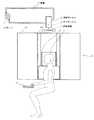
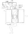
図5に、撮影時のマグネットシステム11と被験者31およびRFコイル部33の相互関係を、風供給装置とともに示す。同図に示すように、被験者31の頭部およびRFコイル部33が、マグネットシステム11の中心すなわちマグネットセンタ(magnet center)の撮影領域に位置する。
【0035】
マグネットシステム11の上部にはボアに対向して回転羽根71が設けられている。回転羽根71は例えば扇風機等の回転羽根と同様な構造を有し、その回転によってマグネットシステム11の内部空間に風を送り込むものである。回転羽根71は本発明における回転羽根の実施の形態の一例である。
【0036】
回転羽根71にはギヤボックス(gear box)73を介して液体モーター(motor)75から回転力が与えられる。液体モーター75は、そのケーシング(casing)の内部に図示しない回転子すなわち水車を有し、この水車が、配管77を通じて循環する例えば水や油等の液体で駆動されて回転する。液体の循環は、マグネットシステム11から十分離れた位置に設置したポンプ(pump)79によって行われる。
【0037】
水車の回転はギヤボックス73を介して回転羽根71に伝えられる。ギヤボックス73内ではギヤの切り換えが可能になっており、これによって回転羽根71の回転数が調節可能となっている。また、クラッチ(clutch)を内蔵しそのオン・オフにより液体モーター75から回転羽根71への動力の伝達を断続できるようになっている。
【0038】
ギヤの切り換えおよびクラッチのオン・オフは制御部161によって制御される。なお、これを手動で行っても良いのはいうまでもない。71なお、回転数を調節する必要がないときはギヤボックス73は省略可能である。
【0039】
回転羽根71、ギヤボックス73および液体モーター75は、例えばプラスチックス(plastics)やセラミックス(ceramics)等の非磁性材料ないし非金属材料で構成される。配管77も同様である。なお、配管77はゴム(gum)管等で構成しても良い。
【0040】
このような送風装置では、液体モーター75は一切電気を用いないので、磁気共鳴信号に対し電磁的な妨害信号を発生することがない。また、液体モーター75、ギヤボックス73および回転羽根71をプラスチックスやセラミックス等の非磁性材料ないし非金属材料で構成したので、その動作がマグネットシステム11の磁気的環境を乱すこともない。
【0041】
このため、これらのものをマグネットシステム11のボアの入り口のごく近傍に配置することができる。あるいは、必要に応じてマグネットシステム11の内部空間に配置することも可能である。そして、このような配置によって、送風損失の少ないすなわち効率の良い送風を行うことができる。
【0042】
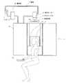
回転羽根71の回転数の調節は、図6に示すように、配管77に設けた制御弁81で液体の流量を調節することにより行うようにしても良い。制御弁81は本発明における調節手段の実施の形態の一例である。流量調節弁81も非磁性材料ないし非金属材料で構成される。なお、マグネットシステム11から十分離して設置する場合は必ずしもその必要はない。
【0043】
流量調節弁81による送風量調節は、制御部161による自動調節または操作者35による手動調節により行われる。あるいは、流量調節弁81によらずポンプ79の回転数を自動または手動で制御することにより送風量を調節するようにしても良い。また、流量調節弁81による調節とポンプ79による調節を併用しても良いのはいうまでもない。
【0044】
送風量の調節は、図7に示すように、液体モーター75をパイパス(bypass)する管路83に設けた流量調節弁81により、液体モーター75に供給する流量と管路83に供給する流量の比を調節することによって行うようにしても良い。流量調節弁81は本発明における調節手段の実施の形態の一例である。
【0045】
マグネットシステム11の主磁場コイルを常伝導コイルで構成した場合は、常伝導コイルの発熱による温度上昇を抑制するために、液体による常伝導コイルの冷却が行われる。また、超伝導コイルを用いる場合であっても、勾配コイルの温度上昇を抑制する必要があるときは、液体による冷却を行うことがあり得る。マグネットシステム11がそのような液体冷却装置を備えている場合は、冷却液の流動を利用して液体モーター75を回すようにしても良い。
【0046】
すなわち、図8に示すように、放熱器85で放熱しながらマグネットシステム11内の例えば主磁場コイルや勾配コイル等の被冷却部分を冷却する液体をポンプ79で循環させる場合、循環経路中に液体モーター75を設ける。これによって、冷却系と液体モーター駆動系を合わせた構成を簡素化することができる。
【0047】
このような構成で、ギヤボックス73のギヤの切換やクラッチのオン・オフにより、送風量を適切に調節する。このようにして送風量を調節しても液体の流量は変わらないので、冷却能力に影響することなく送風量を調節することができる。
【0048】
あるいは、図9に示すように、冷却液の循環経路中に液体モーター75、それをバイパスする管路83および管路83に設けた流量調節弁81により、液体モーター75に流れる液体流量と管路83に流れる液体流量の比を調節し、送風量を適切に調節する。流量比を調節しても全体の流量は変わらないので、冷却能力に影響することなく送風量を調節することができる。
【0049】
本装置の動作を説明する。操作者35は、先ず、ピット21内に下降している座席43に被験者31を着席させ、その頭部をRFコイル部33内に収容する。次に、スイッチ47を操作して座席昇降機構41を作動させ、座席43を上昇させ、図5に示した撮影位置まで搬送する。
【0050】
この状態で液体モーター75を作動させてマグネットシステム11の内部空間に風を送り込む。送風は内部空間に被験者31が存在している間は継続的に行われる。これによって、被験者31は狭い空間内でも涼感を感じることができる。
【0051】
次に、操作者35は操作部191を操作して撮影を開始する。撮影は制御部161による制御の下で進行する。図10に、磁気共鳴撮影に用いるパルスシーケンス(pulse sequence)の一例を示す。このパルスシーケンスは、スピンエコー(SE:Spin Echo)法のパルスシーケンスである。
【0052】
すなわち、(1)はSE法におけるRF励起用の90°パルスおよび180°パルスのシーケンスであり、(2)、(3)、(4)および(5)は、同じくそれぞれ、スライス勾配Gs、リードアウト勾配Gr、フェーズエンコード勾配GpおよびスピンエコーMRのシーケンスである。なお、90°パルスおよび180°パルスはそれぞれ中心信号で代表する。パルスシーケンスは時間軸tに沿って左から右に進行する。
【0053】
同図に示すように、90°パルスによりスピンの90°励起が行われる。このときスライス勾配Gsが印加され所定のスライスについての選択励起が行われる。90°励起から所定の時間後に、180°パルスによる180°励起すなわちスピン反転が行われる。このときもスライス勾配Gsが印加され、同じスライスについての選択的反転が行われる。
【0054】
90°励起とスピン反転の間の期間に、リードアウト勾配Grおよびフェーズエンコード勾配Gpが印加される。リードアウト勾配Grによりスピンのディフェーズ(dephase)が行われる。フェーズエンコード勾配Gpによりスピンのフェーズエンコードが行われる。
【0055】
スピン反転後、リードアウト勾配Grでスピンをリフェーズ(rephase)してスピンエコーMRを発生させる。スピンエコーMRは、エコー中心に関して対称的な波形を持つRF信号となる。中心エコーは90°励起からTE(echo time)後に生じる。スピンエコーMRはデータ収集部151によりビューデータ(view data)として収集される。このようなパスルシーケンスが周期TR(repetition time)で64〜512回繰り返される。繰り返しのたびにフェーズエンコード勾配Gpを変更し、毎回異なるフェーズエンコードを行う。これによって、64〜512ビューのビューデータが得られる。
【0056】
磁気共鳴撮影用パルスシーケンスの他の例を図11に示す。このパルスシーケンスは、グラディエントエコー(GRE:Gradient Echo)法のパルスシーケンスである。
【0057】
すなわち、(1)はGRE法におけるRF励起用のα°パルスのシーケンスであり、(2)、(3)、(4)および(5)は、同じくそれぞれ、スライス勾配Gs、リードアウト勾配Gr、フェーズエンコード勾配GpおよびグラディエントエコーMRのシーケンスである。なお、α°パルスは中心信号で代表する。パルスシーケンスは時間軸tに沿って左から右に進行する。
【0058】
同図に示すように、α°パルスによりスピンのα°励起が行われる。αは90以下である。このときスライス勾配Gsが印加され所定のスライスについての選択励起が行われる。
【0059】
α°励起後、フェーズエンコード勾配Gpによりスピンのフェーズエンコードが行われる。次に、リードアウト勾配Grにより先ずスピンをディフェーズし、次いでスピンをリフェーズして、グラディエントエコーMRを発生させる。グラディエントエコーMRは、エコー中心に関して対称的な波形を持つRF信号となる。中心エコーはα°励起からTE後に生じる。
【0060】
グラディエントエコーMRはデータ収集部151によりビューデータとして収集される。このようなパスルシーケンスが周期TRで64〜512回繰り返される。繰り返しのたびにフェーズエンコード勾配Gpを変更し、毎回異なるフェーズエンコードを行う。これによって、64〜512ビューのビューデータが得られる。
【0061】
図10または図11のパルスシーケンスによって得られたビューデータが、データ処理部171のメモリに収集される。なお、パルスシーケンスはSE法またはGRE法に限るものではなく、例えばファーストスピンエコー(FSE:Fast Spin Echo)法やエコープラナーイメージング(EPI:Echo Planar Imaging)等、他の適宜の技法のものであって良いのはいうまでもない。
【0062】
データ処理部171は、ビューデータを2次元逆フーリエ変換して被験者31の頭部の断層像を再構成する。再構成画像は表示部181により可視像として表示される。
【0063】
このような撮影を被験者31に所定のキーボード操作を行わせながら撮影し、得られた画像に基づいて被験者31の脳の機能を調べる。キーボード操作を被験者31の上体が起きた状態で行うので、人間が通常に行動するのと同様な状態で操作をすることができる。これによって、通常行動時の脳の機能を正しく撮影することができる。
【0064】
なお、被験者31が上記のような手指の操作を行う場合ばかりでなく、例えば、言語発音や歌唱あるいは想念の想起等を行うときの脳の状態を撮影する場合も、通常行動時の脳の機能を正しく撮影することができる。また、聴覚、味覚、嗅覚、触覚等の感覚器官の刺激に対する脳の振る舞いを撮影する場合も同様である。
【0065】
以上は、マグネットシステムが縦型ボアマグネットシステムである例であるが、マグネットシステムは縦型ボアマグネットシステムに限るものではなく、ボアが水平方向を向く横型ボアマグネットシステムを採用した磁気共鳴撮影装置についても、上記と同様な風供給装置を設けることができる。
【0066】
そのような磁気共鳴撮影装置におけるマグネットシステム部分の構成例を、図12、図13、図14、図15および図16にそれぞれ示す。これらの図において図5、図6、図7、図8および図9に示したものと同様の部分は、同一の符号を付して説明を省略する。
【0067】
図12に示したものは横型ボアマグネットシステムに、図5に示したものと同様な風供給素値を設けたものである。同様に、図13、図14、図15および図16に示したものは横型ボアマグネットシステムに、それぞれ、図6、図7、図8および図9に示したものと同様な風供給装置を設けたものである。
【0068】
これらの図に示すように、マグネットシステム11の内部空間は、水平な中心軸を持つ柱状の空間となる。被験者31は支持板91に載置されてマグネットシステムの内部空間に搬入および搬出される。RFコイル部33は支持板91に取り付けられている。このような内部空間に、液体モーター75によって回転する回転羽根71により風が送り込まれる。
【0069】
以上、画像撮影装置が磁気共鳴撮影装置である例で本発明を説明したが、画像撮影装置は磁気共鳴撮影装置に限るものではなく、撮影対象を収容する空間を持つ信号獲得装置を用いる、例えばPET(Positron EmissionTomography)、ガンマカメラ(γ camera)、X線CT(Computed Tomography)装置等、他の方式の画像撮影装置であって良い。
【0070】
【発明の効果】
以上詳細に説明したように、本発明によれば、効率が良い風供給装置、そのような風供給装置を備えた信号獲得装置および画像撮影装置を実現することができる。
【図面の簡単な説明】
【図1】本発明の実施の形態の一例の装置のブロック図である。
【図2】図1に示した装置のマグネットシステムの外観を待機状態の撮影対象とともに示す斜視図である。
【図3】図1に示した装置のマグネットシステムの外観を待機状態の撮影対象および操作者とともに示す側面図である。
【図4】図1に示した装置のマグネットシステムの外観を撮影状態の撮影対象とともに示す斜視図である。
【図5】撮影状態における撮影対象とマグネットシステムと風供給装置との関係を示す図である。
【図6】撮影状態における撮影対象とマグネットシステムと風供給装置との関係を示す図である。
【図7】撮影状態における撮影対象とマグネットシステムと風供給装置との関係を示す図である。
【図8】撮影状態における撮影対象とマグネットシステムと風供給装置との関係を示す図である。
【図9】撮影状態における撮影対象とマグネットシステムと風供給装置との関係を示す図である。
【図10】図1に示した装置が実行するパルスシーケンスの一例を示す模式図である。
【図11】図1に示した装置が実行するパルスシーケンスの一例を示す模式図である。
【図12】撮影状態における撮影対象と横型ボアマグネットシステムと風供給装置との関係を示す図である。
【図13】撮影状態における撮影対象と横型ボアマグネットシステムと風供給装置との関係を示す図である。
【図14】撮影状態における撮影対象と横型ボアマグネットシステムと風供給装置との関係を示す図である。
【図15】撮影状態における撮影対象と横型ボアマグネットシステムと風供給装置との関係を示す図である。
【図16】撮影状態における撮影対象と横型ボアマグネットシステムと風供給装置との関係を示す図である。
【符号の説明】
11 マグネットシステム
101 主磁場マグネット部
105 勾配コイル部
33 RFコイル部
111 座席駆動部
131 勾配駆動部
141 RF駆動部
171 データ収集部
161 制御部
171 データ処理部
181 表示部
191 操作部
31 被験者
71 回転羽根
73 ギヤボックス
75 液体モーター
77 配管
79 ポンプ
81 流量調節弁[0001]
BACKGROUND OF THE INVENTION
The present invention relates to a wind supply device, a signal acquisition device, and an image capturing device, and more particularly, to a device that supplies wind to a space that accommodates a measurement object and the like, and a signal acquisition device and an image capturing device including such a wind supply device. .
[0002]
[Prior art]
In a magnetic resonance imaging (MRI) apparatus, an imaging object is carried into an internal space of a magnet system, that is, an imaging space in which a static magnetic field is formed, and a gradient magnetic field and a high-frequency magnetic field are applied to the imaging object. A magnetic resonance signal is generated therein, and a tomographic image is generated (reconstructed) based on the received signal.
[0003]
In order to give a cool feeling to the object to be photographed, wind is sent into the photographing space. When blowing air, an electric blower arranged at a location sufficiently away from the shooting space is sent to the shooting space through a blower duct so that the magnetic resonance signal is not interfered with electromagnetic interference by the electric blower. .
[0004]
[Problems to be solved by the invention]
The wind supply device as described above is inefficient due to energy loss in the air duct.
[0005]
Therefore, an object of the present invention is to realize an efficient wind supply device, a signal acquisition device and an image capturing device including such a wind supply device.
[0006]
[Means for Solving the Problems]
(1) In one aspect of the invention for solving the above-described problem, a liquid motor driven by a flowing liquid and rotating, and a space driven by the liquid motor and containing an object to be supplied with wind are provided. It is provided with the rotary blade which produces.
[0007]
In this aspect of the invention, wind is generated by the rotating blades that use the liquid motor as a power source. Since the liquid motor does not generate an electromagnetic interference signal, it can generate wind in the vicinity of the wind supply target and can perform efficient air blowing.
[0008]
(2) In another aspect of the invention for solving the above problems, a signal acquisition means having a space for accommodating a signal acquisition object, a liquid motor driven and rotated by a flowing liquid, and the liquid motor A signal acquisition device comprising: a rotary blade that is driven to generate wind in the space; and a rotation transmission unit that transmits the rotation of the rotary blade to the rotary blade.
[0009]
In this aspect of the invention, wind is generated by the rotating blades that use the liquid motor as a power source. Since the liquid motor does not generate an electromagnetic interference signal, wind can be generated in the vicinity of the signal acquisition target, and efficient air blowing can be performed.
[0010]
(3) In another aspect of the invention for solving the above-mentioned problem, the signal acquisition means has a cooled part cooled by a liquid, and the liquid motor cools the cooled part. The signal acquisition device according to (2), which is driven by
[0011]
In the invention in this aspect, since the liquid motor is rotated by the liquid for cooling the signal acquisition means, the configuration combining the cooling system and the liquid motor drive system can be simplified.
[0012]
(4) In another aspect of the invention for solving the above-described problem, an image photographing means having a space for accommodating a photographing object, a liquid motor driven and rotated by a flowing liquid, and driven by the liquid motor An image photographing apparatus comprising: a rotary blade that generates wind in the space.
[0013]
In this aspect of the invention, wind is generated by the rotating blades that use the liquid motor as a power source. Since the liquid motor does not generate an electromagnetic interference signal, it can generate wind in the vicinity of the object to be photographed and can efficiently blow air.
[0014]
(5) In another aspect of the invention for solving the above-described problem, the image photographing means has a cooled part cooled by a liquid, and the liquid motor cools the cooled part. The image capturing device according to (4), which is driven by
[0015]
In the invention from this viewpoint, since the liquid motor is rotated by the liquid for cooling the image photographing means, the combined configuration of the cooling system and the liquid motor drive system can be simplified.
[0016]
DETAILED DESCRIPTION OF THE INVENTION
Hereinafter, embodiments of the present invention will be described in detail with reference to the drawings. The present invention is not limited to the embodiment. FIG. 1 shows a block diagram of the magnetic resonance imaging apparatus. This apparatus is an example of an embodiment of the present invention. An example of an embodiment relating to the apparatus of the present invention is shown by the configuration of the apparatus.
[0017]
As shown in FIG. 1, the apparatus has a
[0018]
Although not shown in this figure, the
[0019]
A
[0020]
The head of the subject 31 is accommodated in an RF coil (radio frequency coil)
[0021]
The main magnetic
[0022]
The
[0023]
The
[0024]
The
[0025]
The seat driving unit 111, the
[0026]
An output signal of the
[0027]
The
[0028]
The portion comprising the
[0029]
2 and 3 show the appearance of the
[0030]
A
[0031]
In front of the subject 31, a
[0032]
One of the
[0033]
The seat driving unit 111 moves the seat 43 up and down via the seat lifting mechanism 41 according to the command. That is, when photographing, the seat 43 is raised to bring the subject 31 into the photographing space together with the
[0034]
FIG. 5 shows the interrelationship between the
[0035]
A
[0036]
A rotational force is applied to the
[0037]
The rotation of the water wheel is transmitted to the
[0038]
The gear switching and the on / off of the clutch are controlled by the
[0039]
The
[0040]
In such a blower, the
[0041]
For this reason, these can be arranged very close to the bore entrance of the
[0042]
As shown in FIG. 6, the rotation speed of the
[0043]
The air volume adjustment by the flow
[0044]
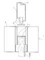
As shown in FIG. 7, the air flow rate is adjusted by adjusting the flow rate supplied to the
[0045]
When the main magnetic field coil of the
[0046]
That is, as shown in FIG. 8, when a
[0047]
With such a configuration, the air flow rate is appropriately adjusted by switching the gear of the
[0048]
Alternatively, as shown in FIG. 9, the liquid flow rate and the pipe line flowing through the
[0049]
The operation of this apparatus will be described. First, the operator 35 seats the subject 31 on the seat 43 descending in the
[0050]
In this state, the
[0051]
Next, the operator 35 operates the
[0052]
That is, (1) is a sequence of 90 ° pulses and 180 ° pulses for RF excitation in the SE method, and (2), (3), (4) and (5) are respectively the slice gradient Gs and the lead. This is a sequence of an out gradient Gr, a phase encode gradient Gp, and a spin echo MR. The 90 ° pulse and the 180 ° pulse are represented by center signals. The pulse sequence proceeds from left to right along the time axis t.
[0053]
As shown in the figure, 90 ° excitation of spin is performed by a 90 ° pulse. At this time, the slice gradient Gs is applied, and selective excitation for a predetermined slice is performed. After a predetermined time from the 90 ° excitation, 180 ° excitation by a 180 ° pulse, that is, spin inversion is performed. At this time, the slice gradient Gs is applied, and selective inversion is performed for the same slice.
[0054]
In the period between 90 ° excitation and spin reversal, a readout gradient Gr and a phase encode gradient Gp are applied. Spin dephase is performed by the lead-out gradient Gr. Spin phase encoding is performed by the phase encoding gradient Gp.
[0055]
After the spin inversion, the spin is rephased at the readout gradient Gr to generate the spin echo MR. The spin echo MR is an RF signal having a symmetrical waveform with respect to the echo center. The central echo occurs after TE (echo time) from 90 ° excitation. The spin echo MR is collected as view data by the
[0056]
Another example of a magnetic resonance imaging pulse sequence is shown in FIG. This pulse sequence is a pulse sequence of a gradient echo (GRE) method.
[0057]
That is, (1) is a sequence of α ° pulses for RF excitation in the GRE method, and (2), (3), (4) and (5) are respectively slice gradient Gs, readout gradient Gr, It is a sequence of a phase encoding gradient Gp and a gradient echo MR. The α ° pulse is represented by a center signal. The pulse sequence proceeds from left to right along the time axis t.
[0058]
As shown in the figure, the α ° excitation of the spin is performed by the α ° pulse. α is 90 or less. At this time, the slice gradient Gs is applied, and selective excitation for a predetermined slice is performed.
[0059]
After the α ° excitation, spin phase encoding is performed by the phase encoding gradient Gp. Next, the spin is first dephased by the readout gradient Gr, and then the spin is rephased to generate a gradient echo MR. The gradient echo MR is an RF signal having a symmetrical waveform with respect to the echo center. The central echo occurs after TE from α ° excitation.
[0060]
The gradient echo MR is collected as view data by the
[0061]
View data obtained by the pulse sequence of FIG. 10 or FIG. 11 is collected in the memory of the
[0062]
The
[0063]
Such photographing is performed while the subject 31 performs a predetermined keyboard operation, and the function of the brain of the subject 31 is examined based on the obtained image. Since the keyboard operation is performed in a state where the upper body of the subject 31 is raised, the operation can be performed in a state similar to a normal action of a human. As a result, the brain function during normal action can be captured correctly.
[0064]
It should be noted that not only when the subject 31 performs the finger operation as described above, but also when, for example, photographing the state of the brain when performing language pronunciation, singing, recalling a thought, etc., the function of the brain during normal action Can be photographed correctly. The same applies to photographing the behavior of the brain in response to stimuli of sensory organs such as hearing, taste, smell, and touch.
[0065]
The above is an example in which the magnet system is a vertical bore magnet system. However, the magnet system is not limited to the vertical bore magnet system, but a magnetic resonance imaging apparatus that employs a horizontal bore magnet system in which the bore faces in the horizontal direction. Also, a wind supply device similar to the above can be provided.
[0066]
Examples of the configuration of the magnet system portion in such a magnetic resonance imaging apparatus are shown in FIGS. 12, 13, 14, 15, and 16, respectively. In these drawings, the same parts as those shown in FIGS. 5, 6, 7, 8, and 9 are denoted by the same reference numerals, and description thereof is omitted.
[0067]
FIG. 12 shows a horizontal bore magnet system provided with a wind supply element value similar to that shown in FIG. Similarly, in FIGS. 13, 14, 15 and 16, the horizontal bore magnet system is provided with a wind supply device similar to that shown in FIGS. 6, 7, 8 and 9, respectively. It is a thing.
[0068]
As shown in these drawings, the internal space of the
[0069]
As described above, the present invention has been described with an example in which the image capturing apparatus is a magnetic resonance imaging apparatus. However, the image capturing apparatus is not limited to a magnetic resonance imaging apparatus, and uses a signal acquisition apparatus having a space for accommodating an imaging target. It may be an image photographing apparatus of another system such as a PET (Positron Emission Tomography), a gamma camera (γ camera), an X-ray CT (Computed Tomography) apparatus.
[0070]
【The invention's effect】
As described above in detail, according to the present invention, it is possible to realize an efficient wind supply device, a signal acquisition device and an image capturing device including such a wind supply device.
[Brief description of the drawings]
FIG. 1 is a block diagram of an exemplary apparatus according to an embodiment of the present invention.
2 is a perspective view showing an appearance of a magnet system of the apparatus shown in FIG. 1 together with an imaging target in a standby state.
FIG. 3 is a side view showing the appearance of the magnet system of the apparatus shown in FIG. 1 together with an imaging target and an operator in a standby state.
4 is a perspective view showing an appearance of a magnet system of the apparatus shown in FIG. 1 together with a subject to be photographed in a photographing state.
FIG. 5 is a diagram illustrating a relationship among an imaging target, a magnet system, and a wind supply device in an imaging state.
FIG. 6 is a diagram illustrating a relationship among a photographing target, a magnet system, and a wind supply device in a photographing state.
FIG. 7 is a diagram illustrating a relationship among a photographing target, a magnet system, and a wind supply device in a photographing state.
FIG. 8 is a diagram illustrating a relationship among an imaging target, a magnet system, and a wind supply device in an imaging state.
FIG. 9 is a diagram illustrating a relationship among a photographing target, a magnet system, and a wind supply device in a photographing state.
FIG. 10 is a schematic diagram showing an example of a pulse sequence executed by the apparatus shown in FIG.
11 is a schematic diagram showing an example of a pulse sequence executed by the apparatus shown in FIG. 1. FIG.
FIG. 12 is a diagram showing a relationship among a subject to be photographed, a horizontal bore magnet system, and a wind supply device in a photographing state.
FIG. 13 is a diagram showing a relationship among a photographing target, a horizontal bore magnet system, and a wind supply device in a photographing state.
FIG. 14 is a diagram illustrating a relationship among a subject to be photographed, a horizontal bore magnet system, and a wind supply device in a photographing state.
FIG. 15 is a diagram illustrating a relationship among a photographing target, a horizontal bore magnet system, and a wind supply device in a photographing state.
FIG. 16 is a diagram illustrating a relationship among a subject to be photographed, a horizontal bore magnet system, and a wind supply device in a photographing state.
[Explanation of symbols]
DESCRIPTION OF
Claims (12)
Translated fromJapanese流動する液体で駆動されて回転する液体モーターと、
前記液体モーターで駆動され前記空間に風を生じさせる回転羽根と、
を具備することを特徴とする信号獲得装置。A signal acquisition means having a space for accommodating a signal acquisition target;
A liquid motor driven by a flowing liquid and rotating;
A rotating blade driven by the liquid motor to generate wind in thespace ;
Asignal acquisition device comprising:
を具備することを特徴とする請求項1に記載の信号獲得装置。Adjusting means for adjusting the flow rate of liquid supplied to the liquid motor;
Thesignal acquisition apparatus according to claim 1, further comprising:
を具備することを特徴とする請求項1に記載の信号獲得装置。Adjusting means for adjusting a ratio of a liquid flow rate supplied to the liquid motor and a liquid flow rate bypassing the liquid motor;
Thesignal acquisition apparatus according to claim 1, further comprising:
前記液体モーターは前記被冷却部分を冷却するための液体で駆動される、
ことを特徴とする請求項1または請求項3に記載の信号獲得装置。The signal acquisition means has a portion to be cooled that is cooled with a liquid,
The liquid motor is driven by a liquid for cooling the cooled part;
The signal acquisition apparatus according toclaim 1 or claim 3, wherein
ことを特徴とする請求項1ないし請求項4のうちのいずれか1つに記載の信号獲得装置。Thesignal acquisition means acquires a signal using magnetic resonance;
The signal acquisition device according to claim1 , wherein the signal acquisition device is a signal acquisition device.
ことを特徴とする請求項1ないし請求項5のうちのいずれか1つに記載の信号獲得装置。Therotary blade and the liquid motor are made of a nonmagnetic material or a nonmetallic material,
The signal acquisition apparatus according to claim1 , wherein the signal acquisition apparatus is a signal acquisition apparatus.
流動する液体で駆動されて回転する液体モーターと、
前記液体モーターで駆動されて前記空間に風を生じさせる回転羽根と、
を具備することを特徴とする画像撮影装置。Image photographing means having a space for accommodating a photographing object;
A liquid motor driven by a flowing liquid and rotating;
A rotating blade driven by the liquid motor to generate wind in the space;
Animage photographing apparatuscomprising:
を具備することを特徴とする請求項7に記載の画像撮影装置。Adjusting means for adjusting the flow rate of liquid supplied to the liquid motor;
Theimage photographing device according to claim7 , furthercomprising:
を具備することを特徴とする請求項7に記載の画像撮影装置。Adjusting means for adjusting a ratio of a liquid flow rate supplied to the liquid motor and a liquid flow rate bypassing the liquid motor;
Theimage photographing device according to claim7 , furthercomprising:
前記液体モーターは前記被冷却部分を冷却するための液体で駆動される、
ことを特徴とする請求項7または請求項9に記載の画像撮影装置。The image photographing means has a cooled part cooled by a liquid,
The liquid motor is driven by a liquid for cooling the cooled part;
The image photographing device according toclaim 7 or 9, wherein
ことを特徴とする請求項7ないし請求項10のうちのいずれか1つに記載の画像撮影装置。Theimage capturing means captures an image using magnetic resonance;
The image photographing device according to claim7 , wherein the image photographing device is a device.
ことを特徴とする請求項7ないし請求項11のうちのいずれか1つに記載の画像撮影装置。Therotary blade and the liquid motor are made of a nonmagnetic material or a nonmetallic material,
The image capturing device according to claim7 , wherein the image capturing device is an image capturing device.
Priority Applications (6)
| Application Number | Priority Date | Filing Date | Title |
|---|---|---|---|
| JP2000027652AJP3679675B2 (en) | 2000-02-04 | 2000-02-04 | Signal acquisition device and image photographing device |
| KR1020017012381AKR100594653B1 (en) | 2000-02-04 | 2001-02-01 | Magnetic resonance imaging device and system |
| PCT/US2001/003311WO2001056493A2 (en) | 2000-02-04 | 2001-02-01 | Air feed device, signal acquisition device and imaging device |
| EP01908780AEP1206215A2 (en) | 2000-02-04 | 2001-02-01 | Air feed device, signal acquisition device and imaging device |
| US09/914,631US6894495B2 (en) | 2000-02-04 | 2001-02-01 | Air feed device, signal acquisition device and imaging device |
| CNB018001815ACN1303940C (en) | 2000-02-04 | 2001-02-01 | Air feed device, signal acquisition device and imaging device |
Applications Claiming Priority (1)
| Application Number | Priority Date | Filing Date | Title |
|---|---|---|---|
| JP2000027652AJP3679675B2 (en) | 2000-02-04 | 2000-02-04 | Signal acquisition device and image photographing device |
Publications (2)
| Publication Number | Publication Date |
|---|---|
| JP2001212105A JP2001212105A (en) | 2001-08-07 |
| JP3679675B2true JP3679675B2 (en) | 2005-08-03 |
Family
ID=18553196
Family Applications (1)
| Application Number | Title | Priority Date | Filing Date |
|---|---|---|---|
| JP2000027652AExpired - Fee RelatedJP3679675B2 (en) | 2000-02-04 | 2000-02-04 | Signal acquisition device and image photographing device |
Country Status (6)
| Country | Link |
|---|---|
| US (1) | US6894495B2 (en) |
| EP (1) | EP1206215A2 (en) |
| JP (1) | JP3679675B2 (en) |
| KR (1) | KR100594653B1 (en) |
| CN (1) | CN1303940C (en) |
| WO (1) | WO2001056493A2 (en) |
Families Citing this family (14)
| Publication number | Priority date | Publication date | Assignee | Title |
|---|---|---|---|---|
| JP3679675B2 (en)* | 2000-02-04 | 2005-08-03 | ジーイー・メディカル・システムズ・グローバル・テクノロジー・カンパニー・エルエルシー | Signal acquisition device and image photographing device |
| US7906966B1 (en) | 2001-10-05 | 2011-03-15 | Fonar Corporation | Quadrature foot coil antenna for magnetic resonance imaging |
| US7701209B1 (en) | 2001-10-05 | 2010-04-20 | Fonar Corporation | Coils for horizontal field magnetic resonance imaging |
| US8401615B1 (en) | 2004-11-12 | 2013-03-19 | Fonar Corporation | Planar coil flexion fixture for magnetic resonance imaging and use thereof |
| US20080039714A1 (en)* | 2006-08-08 | 2008-02-14 | Intermagnetics General Corporation | Magnetic resonance imaging system, a gradient coil, and a method of using the system |
| US9386939B1 (en) | 2007-05-10 | 2016-07-12 | Fonar Corporation | Magnetic resonance imaging of the spine to detect scoliosis |
| JP5472896B2 (en)* | 2007-11-22 | 2014-04-16 | 株式会社東芝 | Magnetic resonance equipment |
| US8599215B1 (en) | 2008-05-07 | 2013-12-03 | Fonar Corporation | Method, apparatus and system for joining image volume data |
| DE102008034685A1 (en)* | 2008-07-25 | 2009-10-29 | Siemens Aktiengesellschaft | Fan device for insertion in scatter field of magnetic field generator of magnetic resonance device, has non-magnetic engine and non-magnetic fan wheel which is actuated by non-magnetic engine |
| JP5582756B2 (en)* | 2008-11-28 | 2014-09-03 | 株式会社東芝 | High frequency coil unit and magnetic resonance diagnostic apparatus |
| CN103720472B (en)* | 2012-10-11 | 2016-06-08 | 西门子(深圳)磁共振有限公司 | For ventilation installation and the magnetic resonance imaging system of magnetic resonance imaging system |
| ES2711672T3 (en) | 2013-03-12 | 2019-05-06 | Fujifilm Corp | Material repair material |
| US9766310B1 (en) | 2013-03-13 | 2017-09-19 | Fonar Corporation | Method and apparatus for magnetic resonance imaging of the cranio-cervical junction |
| JP2022550239A (en)* | 2019-10-03 | 2022-12-01 | ビクトリア リンク リミテッド | inflatable head support |
Family Cites Families (19)
| Publication number | Priority date | Publication date | Assignee | Title |
|---|---|---|---|---|
| US3983715A (en)* | 1974-01-24 | 1976-10-05 | Hair Jr John E | Mobile equipment air-conditioner |
| US4179888A (en)* | 1978-05-18 | 1979-12-25 | Eaton Corporation | Hydraulic fan drive system |
| DE3528821A1 (en)* | 1985-08-10 | 1987-02-12 | Bosch Gmbh Robert | Hydrostatic drive of a fan |
| US5035231A (en)* | 1987-04-27 | 1991-07-30 | Olympus Optical Co., Ltd. | Endoscope apparatus |
| US4960106A (en)* | 1987-04-28 | 1990-10-02 | Olympus Optical Co., Ltd. | Endoscope apparatus |
| DE3729819A1 (en)* | 1987-09-05 | 1989-03-16 | Spectrospin Ag | MAGNETIC ARRANGEMENT FOR NMR SPECTROMETERS |
| US5337845A (en)* | 1990-05-16 | 1994-08-16 | Hill-Rom Company, Inc. | Ventilator, care cart and motorized transport each capable of nesting within and docking with a hospital bed base |
| US5335651A (en)* | 1990-05-16 | 1994-08-09 | Hill-Rom Company, Inc. | Ventilator and care cart each capable of nesting within and docking with a hospital bed base |
| KR100237243B1 (en)* | 1992-07-08 | 2000-01-15 | 구자홍 | Mode memory caption video device |
| US5497776A (en)* | 1993-08-05 | 1996-03-12 | Olympus Optical Co., Ltd. | Ultrasonic image diagnosing apparatus for displaying three-dimensional image |
| US5485850A (en)* | 1993-08-13 | 1996-01-23 | Dietz; Henry G. | Monitor of low pressure intervals with control capabilities |
| US5946220A (en)* | 1993-08-25 | 1999-08-31 | Lemelson; Jerome H. | Computer operated material processing systems and method |
| US5602477A (en)* | 1995-02-06 | 1997-02-11 | The Regents Of The University Of California | Nuclear magnetic resonance freezing sensor |
| JP3110011B2 (en)* | 1998-01-28 | 2000-11-20 | ジーイー横河メディカルシステム株式会社 | MRI apparatus and mobile table |
| JP3040748B2 (en)* | 1998-06-15 | 2000-05-15 | ジーイー横河メディカルシステム株式会社 | Vertical magnet device and MRI device for MRI |
| CN1239834A (en)* | 1998-06-24 | 1999-12-29 | 世大积体电路股份有限公司 | Flash EEPROM |
| CN1191785C (en)* | 1998-07-21 | 2005-03-09 | 通用电器横河医疗系统株式会社 | Magnetic resonance imaging apparatus |
| JP2002521602A (en)* | 1998-07-23 | 2002-07-16 | ソアー インコーポレイテッド | Hydraulic fan drive system with non-dedicated fluid source |
| JP3679675B2 (en)* | 2000-02-04 | 2005-08-03 | ジーイー・メディカル・システムズ・グローバル・テクノロジー・カンパニー・エルエルシー | Signal acquisition device and image photographing device |
- 2000
- 2000-02-04JPJP2000027652Apatent/JP3679675B2/ennot_activeExpired - Fee Related
- 2001
- 2001-02-01USUS09/914,631patent/US6894495B2/ennot_activeExpired - Fee Related
- 2001-02-01EPEP01908780Apatent/EP1206215A2/ennot_activeWithdrawn
- 2001-02-01CNCNB018001815Apatent/CN1303940C/ennot_activeExpired - Fee Related
- 2001-02-01KRKR1020017012381Apatent/KR100594653B1/ennot_activeExpired - Fee Related
- 2001-02-01WOPCT/US2001/003311patent/WO2001056493A2/enactiveApplication Filing
Also Published As
| Publication number | Publication date |
|---|---|
| CN1303940C (en) | 2007-03-14 |
| KR20010110713A (en) | 2001-12-13 |
| US6894495B2 (en) | 2005-05-17 |
| EP1206215A2 (en) | 2002-05-22 |
| WO2001056493A3 (en) | 2002-03-14 |
| JP2001212105A (en) | 2001-08-07 |
| KR100594653B1 (en) | 2006-07-03 |
| US20020135370A1 (en) | 2002-09-26 |
| WO2001056493A2 (en) | 2001-08-09 |
| CN1366455A (en) | 2002-08-28 |
Similar Documents
| Publication | Publication Date | Title |
|---|---|---|
| JP3679675B2 (en) | Signal acquisition device and image photographing device | |
| KR102026008B1 (en) | Stator-less electric motor for a magnetic resonance imaging system and methods thereof | |
| US20050154291A1 (en) | Method of using a small MRI scanner | |
| JP5238689B2 (en) | Magnetic resonance with fast coil mode switching between I-channel linear, Q-channel linear, quadrature and anti-quadrature modes | |
| US20100182007A1 (en) | Establishment of parameters to adjust a magnetic field shim for a magnetic resonance examination of a patient | |
| CN101401723A (en) | MRI apparatus | |
| WO2006028015A1 (en) | Magnetic resonance imaging apparatus and method | |
| JP2007534422A (en) | Magnetic resonance imaging system, magnetic resonance imaging method and computer program | |
| JP6971659B2 (en) | Magnetic resonance imaging device and SAR calculation method | |
| CN112345987A (en) | Active coil for shifting a homogeneous magnetic field space | |
| JP4316126B2 (en) | Visual input supply device, signal acquisition device, and image photographing device | |
| JPH08322815A (en) | MRI equipment | |
| JP4768907B2 (en) | Magnetic resonance imaging apparatus and storage medium | |
| JP2009005759A (en) | Magnetic resonance imaging system | |
| WO2006088453A1 (en) | Method of using a small mri scanner | |
| JP4219063B2 (en) | Magnetic resonance imaging device | |
| JPH0584231A (en) | Magnetic resonance imaging equipment | |
| CN106714680A (en) | Magnetic resonance imaging equipment and control method thereof | |
| JP3292305B2 (en) | Magnetic resonance imaging equipment | |
| JP4219065B2 (en) | Magnetic resonance imaging device | |
| JP2001218749A (en) | Magnetic resonance imaging device and recording medium | |
| US12298369B2 (en) | Dedicated magnetic resonance device | |
| EP4266071A1 (en) | Mr electric properties tomography | |
| JP4795571B2 (en) | Magnetic resonance imaging device | |
| JP3170000B2 (en) | Magnetic resonance imaging equipment |
Legal Events
| Date | Code | Title | Description |
|---|---|---|---|
| A625 | Written request for application examination (by other person) | Free format text:JAPANESE INTERMEDIATE CODE: A625 Effective date:20031210 | |
| A977 | Report on retrieval | Free format text:JAPANESE INTERMEDIATE CODE: A971007 Effective date:20050124 | |
| A131 | Notification of reasons for refusal | Free format text:JAPANESE INTERMEDIATE CODE: A131 Effective date:20050208 | |
| A521 | Request for written amendment filed | Free format text:JAPANESE INTERMEDIATE CODE: A523 Effective date:20050302 | |
| TRDD | Decision of grant or rejection written | ||
| A01 | Written decision to grant a patent or to grant a registration (utility model) | Free format text:JAPANESE INTERMEDIATE CODE: A01 Effective date:20050419 | |
| A61 | First payment of annual fees (during grant procedure) | Free format text:JAPANESE INTERMEDIATE CODE: A61 Effective date:20050513 | |
| R150 | Certificate of patent or registration of utility model | Free format text:JAPANESE INTERMEDIATE CODE: R150 | |
| FPAY | Renewal fee payment (event date is renewal date of database) | Free format text:PAYMENT UNTIL: 20090520 Year of fee payment:4 | |
| FPAY | Renewal fee payment (event date is renewal date of database) | Free format text:PAYMENT UNTIL: 20100520 Year of fee payment:5 | |
| FPAY | Renewal fee payment (event date is renewal date of database) | Free format text:PAYMENT UNTIL: 20100520 Year of fee payment:5 | |
| FPAY | Renewal fee payment (event date is renewal date of database) | Free format text:PAYMENT UNTIL: 20100520 Year of fee payment:5 | |
| FPAY | Renewal fee payment (event date is renewal date of database) | Free format text:PAYMENT UNTIL: 20110520 Year of fee payment:6 | |
| FPAY | Renewal fee payment (event date is renewal date of database) | Free format text:PAYMENT UNTIL: 20120520 Year of fee payment:7 | |
| FPAY | Renewal fee payment (event date is renewal date of database) | Free format text:PAYMENT UNTIL: 20120520 Year of fee payment:7 | |
| FPAY | Renewal fee payment (event date is renewal date of database) | Free format text:PAYMENT UNTIL: 20120520 Year of fee payment:7 | |
| FPAY | Renewal fee payment (event date is renewal date of database) | Free format text:PAYMENT UNTIL: 20130520 Year of fee payment:8 | |
| FPAY | Renewal fee payment (event date is renewal date of database) | Free format text:PAYMENT UNTIL: 20130520 Year of fee payment:8 | |
| FPAY | Renewal fee payment (event date is renewal date of database) | Free format text:PAYMENT UNTIL: 20130520 Year of fee payment:8 | |
| FPAY | Renewal fee payment (event date is renewal date of database) | Free format text:PAYMENT UNTIL: 20140520 Year of fee payment:9 | |
| R250 | Receipt of annual fees | Free format text:JAPANESE INTERMEDIATE CODE: R250 | |
| R250 | Receipt of annual fees | Free format text:JAPANESE INTERMEDIATE CODE: R250 | |
| LAPS | Cancellation because of no payment of annual fees |