JP3679368B2 - Incisional biopsy device and method - Google Patents
Incisional biopsy device and methodDownload PDFInfo
- Publication number
- JP3679368B2 JP3679368B2JP2001579869AJP2001579869AJP3679368B2JP 3679368 B2JP3679368 B2JP 3679368B2JP 2001579869 AJP2001579869 AJP 2001579869AJP 2001579869 AJP2001579869 AJP 2001579869AJP 3679368 B2JP3679368 B2JP 3679368B2
- Authority
- JP
- Japan
- Prior art keywords
- tissue
- cutting tool
- probe
- tissue collection
- window
- Prior art date
- Legal status (The legal status is an assumption and is not a legal conclusion. Google has not performed a legal analysis and makes no representation as to the accuracy of the status listed.)
- Expired - Fee Related
Links
- 238000000034methodMethods0.000titledescription77
- 238000007386incisional biopsyMethods0.000title1
- 238000005520cutting processMethods0.000claimsdescription282
- 210000000481breastAnatomy0.000claimsdescription32
- 239000010409thin filmSubstances0.000claimsdescription11
- 239000012530fluidSubstances0.000claimsdescription9
- 239000012528membraneSubstances0.000claimsdescription2
- 238000002679ablationMethods0.000claims1
- 210000001519tissueAnatomy0.000description286
- 239000000523sampleSubstances0.000description143
- 210000000038chestAnatomy0.000description74
- 210000004872soft tissueAnatomy0.000description50
- 238000001574biopsyMethods0.000description35
- 238000011273incision biopsyMethods0.000description31
- 238000003384imaging methodMethods0.000description21
- 206010028980NeoplasmDiseases0.000description17
- 238000002604ultrasonographyMethods0.000description14
- 201000011510cancerDiseases0.000description10
- 230000008569processEffects0.000description10
- 230000006641stabilisationEffects0.000description10
- 238000011105stabilizationMethods0.000description10
- 208000032843HemorrhageDiseases0.000description9
- 230000003444anaesthetic effectEffects0.000description9
- 239000007788liquidSubstances0.000description9
- 230000000740bleeding effectEffects0.000description8
- 230000006835compressionEffects0.000description8
- 238000007906compressionMethods0.000description8
- 238000009607mammographyMethods0.000description8
- 238000005452bendingMethods0.000description7
- 238000003780insertionMethods0.000description7
- 230000037431insertionEffects0.000description7
- 230000003902lesionEffects0.000description6
- 239000000463materialSubstances0.000description6
- 238000003745diagnosisMethods0.000description5
- 206010027476MetastasesDiseases0.000description4
- 206010071051Soft tissue massDiseases0.000description4
- 230000002159abnormal effectEffects0.000description4
- 210000004883areolaAnatomy0.000description4
- 239000012212insulatorSubstances0.000description4
- 210000004072lungAnatomy0.000description4
- 230000009401metastasisEffects0.000description4
- 238000012545processingMethods0.000description4
- 230000005855radiationEffects0.000description4
- 231100000241scarToxicity0.000description4
- 210000003813thumbAnatomy0.000description4
- 206010018852HaematomaDiseases0.000description3
- 239000008280bloodSubstances0.000description3
- 210000004369bloodAnatomy0.000description3
- 238000004891communicationMethods0.000description3
- 230000006837decompressionEffects0.000description3
- 238000010586diagramMethods0.000description3
- 238000002224dissectionMethods0.000description3
- 239000003814drugSubstances0.000description3
- 229940079593drugDrugs0.000description3
- 239000012634fragmentSubstances0.000description3
- 230000006870functionEffects0.000description3
- 239000003193general anesthetic agentSubstances0.000description3
- 238000002690local anesthesiaMethods0.000description3
- 238000012986modificationMethods0.000description3
- 230000004048modificationEffects0.000description3
- 210000002445nippleAnatomy0.000description3
- 239000004033plasticSubstances0.000description3
- 229920003023plasticPolymers0.000description3
- 230000004044responseEffects0.000description3
- 238000001356surgical procedureMethods0.000description3
- 208000004434CalcinosisDiseases0.000description2
- 208000032544CicatrixDiseases0.000description2
- 239000004677NylonSubstances0.000description2
- 206010030113OedemaDiseases0.000description2
- 208000002193PainDiseases0.000description2
- 238000004458analytical methodMethods0.000description2
- 239000012984antibiotic solutionSubstances0.000description2
- 230000003115biocidal effectEffects0.000description2
- 210000004204blood vesselAnatomy0.000description2
- 239000003795chemical substances by applicationSubstances0.000description2
- 238000007796conventional methodMethods0.000description2
- 230000007547defectEffects0.000description2
- 230000001419dependent effectEffects0.000description2
- 238000005516engineering processMethods0.000description2
- 238000010304firingMethods0.000description2
- 229920002457flexible plasticPolymers0.000description2
- 210000005228liver tissueAnatomy0.000description2
- 230000007774longtermEffects0.000description2
- 238000012544monitoring processMethods0.000description2
- 229910001000nickel titaniumInorganic materials0.000description2
- 229920001778nylonPolymers0.000description2
- 230000036407painEffects0.000description2
- -1polyethylenePolymers0.000description2
- 229920000139polyethylene terephthalatePolymers0.000description2
- 239000005020polyethylene terephthalateSubstances0.000description2
- 230000002980postoperative effectEffects0.000description2
- 238000001959radiotherapyMethods0.000description2
- 230000037387scarsEffects0.000description2
- 229910001285shape-memory alloyInorganic materials0.000description2
- 239000007787solidSubstances0.000description2
- 0*NC(CCC1C2)C1*2*#CChemical compound*NC(CCC1C2)C1*2*#C0.000description1
- 206010002091AnaesthesiaDiseases0.000description1
- 206010006187Breast cancerDiseases0.000description1
- 208000026310Breast neoplasmDiseases0.000description1
- 206010014080EcchymosisDiseases0.000description1
- NNJVILVZKWQKPM-UHFFFAOYSA-NLidocaineChemical compoundCCN(CC)CC(=O)NC1=C(C)C=CC=C1CNNJVILVZKWQKPM-UHFFFAOYSA-N0.000description1
- 206010058467Lung neoplasm malignantDiseases0.000description1
- 239000004698PolyethyleneSubstances0.000description1
- 208000035965Postoperative ComplicationsDiseases0.000description1
- 208000004550Postoperative PainDiseases0.000description1
- 229910000831SteelInorganic materials0.000description1
- RTAQQCXQSZGOHL-UHFFFAOYSA-NTitaniumChemical compound[Ti]RTAQQCXQSZGOHL-UHFFFAOYSA-N0.000description1
- HZEWFHLRYVTOIW-UHFFFAOYSA-N[Ti].[Ni]Chemical compound[Ti].[Ni]HZEWFHLRYVTOIW-UHFFFAOYSA-N0.000description1
- 230000009471actionEffects0.000description1
- 208000009956adenocarcinomaDiseases0.000description1
- 239000000853adhesiveSubstances0.000description1
- 230000001070adhesive effectEffects0.000description1
- 230000037005anaesthesiaEffects0.000description1
- 229940035676analgesicsDrugs0.000description1
- 239000000730antalgic agentSubstances0.000description1
- 230000003466anti-cipated effectEffects0.000description1
- 230000003796beautyEffects0.000description1
- 230000009286beneficial effectEffects0.000description1
- 230000008901benefitEffects0.000description1
- 230000015572biosynthetic processEffects0.000description1
- 208000034158bleedingDiseases0.000description1
- 230000017531blood circulationEffects0.000description1
- 210000001124body fluidAnatomy0.000description1
- 150000001669calciumChemical class0.000description1
- 210000000845cartilageAnatomy0.000description1
- 230000008859changeEffects0.000description1
- 239000011248coating agentSubstances0.000description1
- 238000000576coating methodMethods0.000description1
- 239000002537cosmeticSubstances0.000description1
- 230000008878couplingEffects0.000description1
- 238000010168coupling processMethods0.000description1
- 238000005859coupling reactionMethods0.000description1
- 230000006378damageEffects0.000description1
- 230000001934delayEffects0.000description1
- 238000002405diagnostic procedureMethods0.000description1
- 230000000694effectsEffects0.000description1
- 239000000835fiberSubstances0.000description1
- 238000002695general anesthesiaMethods0.000description1
- 230000035876healingEffects0.000description1
- 238000007489histopathology methodMethods0.000description1
- 230000006872improvementEffects0.000description1
- 238000002347injectionMethods0.000description1
- 239000007924injectionSubstances0.000description1
- 230000009191jumpingEffects0.000description1
- 229960004194lidocaineDrugs0.000description1
- 210000004185liverAnatomy0.000description1
- 201000007270liver cancerDiseases0.000description1
- 208000014018liver neoplasmDiseases0.000description1
- 201000005202lung cancerDiseases0.000description1
- 208000020816lung neoplasmDiseases0.000description1
- 238000004519manufacturing processMethods0.000description1
- 238000005555metalworkingMethods0.000description1
- 201000010879mucinous adenocarcinomaDiseases0.000description1
- 239000013307optical fiberSubstances0.000description1
- 210000000056organAnatomy0.000description1
- 230000001575pathological effectEffects0.000description1
- 230000007170pathologyEffects0.000description1
- 230000035515penetrationEffects0.000description1
- 230000002093peripheral effectEffects0.000description1
- 230000000704physical effectEffects0.000description1
- 238000005498polishingMethods0.000description1
- 229920000573polyethylenePolymers0.000description1
- 238000002360preparation methodMethods0.000description1
- 230000008439repair processEffects0.000description1
- 238000005070samplingMethods0.000description1
- 238000000926separation methodMethods0.000description1
- 230000009919sequestrationEffects0.000description1
- 239000000243solutionSubstances0.000description1
- 230000007480spreadingEffects0.000description1
- 238000003892spreadingMethods0.000description1
- 230000000087stabilizing effectEffects0.000description1
- 239000010935stainless steelSubstances0.000description1
- 229910001220stainless steelInorganic materials0.000description1
- 239000010959steelSubstances0.000description1
- 238000007920subcutaneous administrationMethods0.000description1
- 230000004083survival effectEffects0.000description1
- 230000008719thickeningEffects0.000description1
- 210000000115thoracic cavityAnatomy0.000description1
- 210000001685thyroid glandAnatomy0.000description1
- 230000000451tissue damageEffects0.000description1
- 231100000827tissue damageToxicity0.000description1
- 239000010936titaniumSubstances0.000description1
- 229910052719titaniumInorganic materials0.000description1
- 230000007704transitionEffects0.000description1
- 238000012800visualizationMethods0.000description1
Images


Classifications
- A—HUMAN NECESSITIES
- A61—MEDICAL OR VETERINARY SCIENCE; HYGIENE
- A61B—DIAGNOSIS; SURGERY; IDENTIFICATION
- A61B10/00—Instruments for taking body samples for diagnostic purposes; Other methods or instruments for diagnosis, e.g. for vaccination diagnosis, sex determination or ovulation-period determination; Throat striking implements
- A61B10/02—Instruments for taking cell samples or for biopsy
- A61B10/0233—Pointed or sharp biopsy instruments
- A61B10/0266—Pointed or sharp biopsy instruments means for severing sample
- A—HUMAN NECESSITIES
- A61—MEDICAL OR VETERINARY SCIENCE; HYGIENE
- A61B—DIAGNOSIS; SURGERY; IDENTIFICATION
- A61B10/00—Instruments for taking body samples for diagnostic purposes; Other methods or instruments for diagnosis, e.g. for vaccination diagnosis, sex determination or ovulation-period determination; Throat striking implements
- A61B10/02—Instruments for taking cell samples or for biopsy
- A61B10/04—Endoscopic instruments, e.g. catheter-type instruments
- A—HUMAN NECESSITIES
- A61—MEDICAL OR VETERINARY SCIENCE; HYGIENE
- A61B—DIAGNOSIS; SURGERY; IDENTIFICATION
- A61B17/00—Surgical instruments, devices or methods
- A61B17/32—Surgical cutting instruments
- A61B17/3205—Excision instruments
- A61B17/3207—Atherectomy devices working by cutting or abrading; Similar devices specially adapted for non-vascular obstructions
- A61B17/320725—Atherectomy devices working by cutting or abrading; Similar devices specially adapted for non-vascular obstructions with radially expandable cutting or abrading elements
- A—HUMAN NECESSITIES
- A61—MEDICAL OR VETERINARY SCIENCE; HYGIENE
- A61B—DIAGNOSIS; SURGERY; IDENTIFICATION
- A61B18/00—Surgical instruments, devices or methods for transferring non-mechanical forms of energy to or from the body
- A61B18/04—Surgical instruments, devices or methods for transferring non-mechanical forms of energy to or from the body by heating
- A61B18/12—Surgical instruments, devices or methods for transferring non-mechanical forms of energy to or from the body by heating by passing a current through the tissue to be heated, e.g. high-frequency current
- A61B18/14—Probes or electrodes therefor
- A61B18/1482—Probes or electrodes therefor having a long rigid shaft for accessing the inner body transcutaneously in minimal invasive surgery, e.g. laparoscopy
- A—HUMAN NECESSITIES
- A61—MEDICAL OR VETERINARY SCIENCE; HYGIENE
- A61B—DIAGNOSIS; SURGERY; IDENTIFICATION
- A61B10/00—Instruments for taking body samples for diagnostic purposes; Other methods or instruments for diagnosis, e.g. for vaccination diagnosis, sex determination or ovulation-period determination; Throat striking implements
- A61B10/0041—Detection of breast cancer
- A—HUMAN NECESSITIES
- A61—MEDICAL OR VETERINARY SCIENCE; HYGIENE
- A61B—DIAGNOSIS; SURGERY; IDENTIFICATION
- A61B10/00—Instruments for taking body samples for diagnostic purposes; Other methods or instruments for diagnosis, e.g. for vaccination diagnosis, sex determination or ovulation-period determination; Throat striking implements
- A61B10/02—Instruments for taking cell samples or for biopsy
- A—HUMAN NECESSITIES
- A61—MEDICAL OR VETERINARY SCIENCE; HYGIENE
- A61B—DIAGNOSIS; SURGERY; IDENTIFICATION
- A61B18/00—Surgical instruments, devices or methods for transferring non-mechanical forms of energy to or from the body
- A61B2018/00005—Cooling or heating of the probe or tissue immediately surrounding the probe
- A61B2018/00011—Cooling or heating of the probe or tissue immediately surrounding the probe with fluids
- A—HUMAN NECESSITIES
- A61—MEDICAL OR VETERINARY SCIENCE; HYGIENE
- A61B—DIAGNOSIS; SURGERY; IDENTIFICATION
- A61B18/00—Surgical instruments, devices or methods for transferring non-mechanical forms of energy to or from the body
- A61B2018/00315—Surgical instruments, devices or methods for transferring non-mechanical forms of energy to or from the body for treatment of particular body parts
- A61B2018/00333—Breast
- A—HUMAN NECESSITIES
- A61—MEDICAL OR VETERINARY SCIENCE; HYGIENE
- A61B—DIAGNOSIS; SURGERY; IDENTIFICATION
- A61B18/00—Surgical instruments, devices or methods for transferring non-mechanical forms of energy to or from the body
- A61B18/04—Surgical instruments, devices or methods for transferring non-mechanical forms of energy to or from the body by heating
- A61B18/12—Surgical instruments, devices or methods for transferring non-mechanical forms of energy to or from the body by heating by passing a current through the tissue to be heated, e.g. high-frequency current
- A61B18/14—Probes or electrodes therefor
- A61B2018/1405—Electrodes having a specific shape
- A61B2018/1407—Loop
- A—HUMAN NECESSITIES
- A61—MEDICAL OR VETERINARY SCIENCE; HYGIENE
- A61B—DIAGNOSIS; SURGERY; IDENTIFICATION
- A61B18/00—Surgical instruments, devices or methods for transferring non-mechanical forms of energy to or from the body
- A61B18/04—Surgical instruments, devices or methods for transferring non-mechanical forms of energy to or from the body by heating
- A61B18/12—Surgical instruments, devices or methods for transferring non-mechanical forms of energy to or from the body by heating by passing a current through the tissue to be heated, e.g. high-frequency current
- A61B18/14—Probes or electrodes therefor
- A61B2018/1475—Electrodes retractable in or deployable from a housing
- A—HUMAN NECESSITIES
- A61—MEDICAL OR VETERINARY SCIENCE; HYGIENE
- A61B—DIAGNOSIS; SURGERY; IDENTIFICATION
- A61B90/00—Instruments, implements or accessories specially adapted for surgery or diagnosis and not covered by any of the groups A61B1/00 - A61B50/00, e.g. for luxation treatment or for protecting wound edges
- A61B90/36—Image-producing devices or illumination devices not otherwise provided for
- A61B90/37—Surgical systems with images on a monitor during operation
- A61B2090/378—Surgical systems with images on a monitor during operation using ultrasound
- A61B2090/3782—Surgical systems with images on a monitor during operation using ultrasound transmitter or receiver in catheter or minimal invasive instrument
- A61B2090/3784—Surgical systems with images on a monitor during operation using ultrasound transmitter or receiver in catheter or minimal invasive instrument both receiver and transmitter being in the instrument or receiver being also transmitter
- A—HUMAN NECESSITIES
- A61—MEDICAL OR VETERINARY SCIENCE; HYGIENE
- A61B—DIAGNOSIS; SURGERY; IDENTIFICATION
- A61B2218/00—Details of surgical instruments, devices or methods for transferring non-mechanical forms of energy to or from the body
- A61B2218/001—Details of surgical instruments, devices or methods for transferring non-mechanical forms of energy to or from the body having means for irrigation and/or aspiration of substances to and/or from the surgical site
- A61B2218/002—Irrigation
Landscapes
- Health & Medical Sciences (AREA)
- Life Sciences & Earth Sciences (AREA)
- Surgery (AREA)
- Engineering & Computer Science (AREA)
- Animal Behavior & Ethology (AREA)
- Veterinary Medicine (AREA)
- Biomedical Technology (AREA)
- Heart & Thoracic Surgery (AREA)
- Medical Informatics (AREA)
- Molecular Biology (AREA)
- Public Health (AREA)
- General Health & Medical Sciences (AREA)
- Nuclear Medicine, Radiotherapy & Molecular Imaging (AREA)
- Pathology (AREA)
- Vascular Medicine (AREA)
- Physics & Mathematics (AREA)
- Plasma & Fusion (AREA)
- Otolaryngology (AREA)
- Radiology & Medical Imaging (AREA)
- Surgical Instruments (AREA)
- Ultra Sonic Daignosis Equipment (AREA)
Description
Translated fromJapanese【0001】
【発明の背景】
1.産業上の利用分野
本発明は、軟性組織切開生検装置およびその方法の分野に関する。特に、本発明は胸部組織のような軟性組織から疑わしい患部を切除するための装置およびその方法の分野に関する。
【0002】
2.従来の技術
乳癌は女性にとって大きな脅威である。患者の生存期間を改善するためには、乳房内の癌患部ならびにその疑いがある部分を早期に発見し処置する必要がある。従って、女性においては毎月の自己乳房診断および毎年の医師による乳房診断のみでなく、40歳以降は年次的にマンモグラフィ投影を受けることが奨励されている。マンモグラフィは、今日において、小さく触診不可能な患部を発見するための唯一の方法である。これらの触診不可能な患部は、通常の乳部組織、脂肪、または微細カルシウム分のクラスタに比して濃い不透明部分として現れる。
【0003】
マンモグラフィによって発見された触診不可能な患部を診断、位置判定および切開するための一般的な方法は、時間を浪費する多段階のプロセスからなる。まず患者は放射線科に行き、そこで放射線専門医がマンモグラフィまたは超音波誘導装置を使って患部を発見および位置判定する。位置判定されると、放射線反射投影線を胸部内に挿入する。線の遠位の末端は小さなフックまたはループを備えることができる。好適には、これは生検される疑いのある部分に近接して配置される。その後、患者は手術室に搬送される。全身または局部麻酔を行った上で、外科医がいわゆるニードルロカライズド胸部生検を実施する。ニードルロカライズド胸部生検において、外科医は予め患者の胸部内に設置した線によって誘導され、線の遠位の端部周辺の細胞の塊を切開する。この標本は、放射線科に搬送され、そこで標本の放射線影像が撮られ、切断された標本内に疑わしい患部が含まれているかどうかが判定される。その間、外科医、患者、麻酔医および手術室スタッフは、手術室内で手術を実施する前に放射線医からの診断結果を待たなければならない。疑いのある患部は、全ての方向において、正常な胸部細胞の小さな断片または縁部と共に切断することが好適である。正常な細胞の断片を適正に得ることができるかどうかは、外科医の習熟度および経験に大きく依存しており、しばしば標本内に患部が存在することを確保するために過度に多量の正常な胸部細胞を切除することがある。このことは、術後の合併症の危険性を増加させるとともに、出血および永続的な胸部の美観的欠陥をもたらす。今日において、約80%の胸部生検は良性のものであり、多数の女性がこの良性の胸部生検によって不要に永続的な傷跡および美観的な欠陥を被っている。
【0004】
最近においては、疑いのある患部を標本化または生検して組織学的な診断を実施するためにより侵入性の少ない方式が開発されている。新しい技術のうちのもっとも単純なものは、外部超音波診断装置によって患部を視覚化することである。外部超音波によって診る場合、連続的に視覚化することによって患部の生検を行うことができる。この技術によれば、医師は生検針が患部に実際に進入することを見ることができ、従って適正な領域が標本化されることが保持される。外部超音波誘導装置と共に使用される従来の標本化装置は、微細針吸引、コア生検針、または減圧補助付生検装置等を含む。
【0005】
別の従来の技術は、走触性のデジタルマンモグラフィを使用して疑いのある患部を位置判定する。患者は特殊なテーブルの上にうつ伏せになり、このテーブルにはこれに面した胸部を見るための穴が設けられている。胸部は2枚のマンモグラフィ板の間に圧縮され、これは生検される胸部を安定化させるとともに、デジタルマンモグラムの撮影を可能にする。走触的な画像を得るために、30°の間隔をおいて少なくとも2枚の影像を撮影する。患部に照準を合わせたx,y,zの座標がコンピュータによって計算される。さらに、医師はテーブルの下に設置された特殊な機械的ステージを調整し、これは標本を得るために生検装置を胸部に配置するものである。走触テーブルを使用して患部を生検することを可能にする3つの方法が考えられ、それらは:(1)微細針吸引、(2)コア生検針、および(3)減圧補助付コア生検針である。
【0006】
微細針吸引は、患部または疑いのある部分から小さな細胞標本を吸引するために、小さなゲージの針を使用しており、これは通常20ないし25ゲージである。標本はスライド上に塗布され、これは着色され細胞病理学者によって検査される。この技術において、塗布物内の個々の細胞が検査され、組織構造および細胞組織は保存されない。微細針吸引もオペレータの習熟度および経験に大きく依存するものであり、不適正な標本収集または準備によって高い非診断率(約83%まで)をもたらす。
【0007】
コア生検針は、患部を標本化するためにより大きなサイズの針を使用し、通常14ゲージのものを使用する。この方法によれば、細胞構造および細胞組織が保存される。外側切断カニューレを備えた内側トラフからなる側方切断装置が高速半自動発射操作を行うためのバネ付勢装置に取り付けられている。患部が位置判定された後、局部麻酔が注射され、メスによって皮膚内を小さく切開する。装置は胸部内に進入し、針の先端が胸部内の目標とする患部に誘導される。装置が発射操作される。まず、トラフを備えた内側カニューレが急速に患部内に貫通する。続いて、外側切断カニューレが内側切断カニューレを超えて急速に前進しトラフ内の組織標本を切断する。その後装置全体が除去され標本が取り出される。充分な患部の標本を得るために、胸部および患部内にコア針を複数回進入させることが必要となる。場合によっては10個以上の標本が必要となる。
【0008】
減圧補助付胸部生検システムは、より大きな半自動側方切断装置である。これは通常11ゲージの直径を有し、コア生検針よりも複雑なものとなる。何回も針を挿入することなく患部から複数の大きな標本を得ることができる。組織をトラフ内に吸引するために減圧が加えられる。バネ付勢されたコア針装置を急速に発射操作することに代えて、トラフ内の胸部組織を切断する振動式外側切断カニューレを備えている。医師は外側カニューレがトラフを超えて前進するスピードを調整し、複数の標本を得るためにトラフの位置を時計回りに回転させる。
【0009】
微細針吸引、コア生検針または減圧補助付生検によって悪性腫瘍または異常な肥厚の良性診断を示した場合、患者は別の処置を受ける必要があり、これは旧来の針進入式胸部生検であり、適量の正常な胸部組織の断片を含めて患部を完全に切開する。場合によって、減圧補助付装置は目標とする患部全体を除去する。これが発生すると、生検範囲内に小さなチタンチップを設置する必要がある。このチップは、引き続いて前述した理由により針進入式生検を実施する際に範囲を示すものとなる。
【0010】
患部を生検する別の方法は、0.5ないし2.0cmの直径を有する大きな末端切断コア装置を備えている。これも安定化および位置判定のために走触テーブルを使用する。患部の座標が計算され局部麻酔が注入された後、メスを使用して口径の進入を可能にする大きさの切開が実施される。胸部組織をくりぬいて患部に進入する。標本が検索されると、患者は仰向けにされて、外科医が直視しながら出血血管を焼灼する。0.5ないし2.0cm以上の切開傷が縫合される。
【0011】
走触テーブルは患者にとってきつい姿勢を必要とし、非常に不快なものとなり得る。女性は処置の間中にわたってうつ伏せに寝る必要があり、これは患者によっては不可能なことである。加えて、生検される患部は、マンモグラフィ板の作業領域の中央に位置していなければならない。このことは、患部が胸部後方または脇の下に極めて近い場合、患者にとって非常に困難で不快なものとなる。
【0012】
(1)患部がマンモグラフィ板の作業領域内にあることを確認し、(2)走触的座標を獲得し(少なくとも2つの画像)、(3)組織を採取する前に生検針の位置を確認し、(4)患部が標本化されたことを確認する工程の間中、複数の放射線写真が要求されるため、女性が増加的な放射線にさらされることが強制される。処置の最中に困難が生じた場合、問題を解決するために追加的な放射線の照射が必要となる。
【0013】
コア生検針または減圧補助付装置を使用する際、手動の圧力によってのみ出血が制御される。出血は通常微細針吸引にともなうものではなく、前述の二つの方法において一般的な問題である。斑状出血、胸部水腫、血腫等が発生し得る。これは術後の痛みを増加させ、治癒を遅れさせる。稀には、患者は再手術を受け強固な血腫を制御および除去する必要がある。
【0014】
別の大きな問題は腫瘍の転移である。コア生検針および減圧補助付装置はともに腫瘍内を切開し複数の標本を検査のために切断する。腫瘍を切開すると、癌細胞を除去することができる。同時に血管を切開すると、切断された癌細胞が血流に接することが可能となり、従って元の場所以外に腫瘍が散逸する可能性がある。腫瘍を散逸させることによる長期的な血液により搬送される転移の危険性は、技術的に新しいため、この時点では不明である。しかしながら、針軌道内への癌細胞の散逸に関しては文献例が存在する。癌細胞の生検によって針軌道内へ転移するという報告は数多くなされている。これらのほとんどは、肺および肝臓癌からのものである。しかしながら、胸部粘液性癌腫が針軌道内へ進行した例が一つ報告されている。新生物が針軌道内に散逸することによる長期的な影響も、技術が比較的新しいため不明である。人によっては、腫瘍摘出手術または乳房切除手術にかかわらず、診断された癌の手術治療の最中に針軌道を近辺の皮膚を含めて完全に切除することを推奨している。別の者たちは、術後の放射線治療によって針軌道内に移動した癌細胞を破壊することが可能であると論じている。小さな癌は切開によってのみ治療し術後の放射線治療を実施しない傾向にあるため、癌細胞が針軌道内に転移し進行する危険性が現実的なものとなっている。
【0015】
大きなコアの切断装置(0.5cmないし2.0cm)は、患部をそっくり切除するように設計されているため、一般的に針軌道内への散逸の危険性が無くなる。これは、前述したものと同様に患者にとって不快な走触テーブルが必要となる。手動ではあるが、出血が制御され、患者は処置の終了を待って回転されることが要求される。胸部を安定させ患部を位置判定するために圧縮が使用される。しかしながら、胸部は圧縮板の間でねじられかつゆがめられ、生検後に板が除去された際に後に残った大きなコアの軌道は直線的ではなくねじれたものとなる。これは永久的に乳房の美観を損なうものとなる。
【0016】
胸部内への挿入位置は、医師の手によってではなく機械の中における胸部の位置によって決定される。挿入個所は、通常乳頭輪から離れており、一般的により露出した胸部位置である。微細針吸引、コア生検、減圧補助付装置について、切開部分は通常極めて小さいものであり、傷跡は殆ど気にならないものとなる。しかしながら、大きなコアの生検装置(0.5ないし2.0cm)の場合、大きな切開部分が必要とされる。この大きな切開痕はしばしば美観を損なう傷跡となる。
【0017】
より新しい最小限に侵入する胸部生検装置は、検出された触診不可能な患部のマンモグラフィ診断の可能性をある程度改善するものである。これらの装置は、患者が診断方法を選択することを可能にする。さらに、これらの装置は伝統的な針設置胸部生検に比べて安価なものである。前述した、圧縮、針軌道散逸、血液によって搬送される転移、出血、放射線照射、および走触テーブル上での不快な姿勢等のため、これらの問題を解決するより改善された装置が求められている。さらに、従来の生検装置は、癌が診断された場合に切開部分の縁部分を考慮するものではなく、癌のまわりにおいて適正な縁部が切除されることを保持するために患者は針設置胸部腫瘍摘出手術を受ける必要がある。従って、第二の処置を省略するために、適正な縁部を摘出する問題を解決する装置および方法が必要である。さらに、胸部が圧縮されている間は縁部を判定することができない。
【0018】
【発明の概要】
従って、本発明の目的は、胸部から疑いのある患部を効果的かつ安全に切除することができる装置および方法を提供することである。さらに、本発明の目的は、患部全体をそのまわりにある最小限の正常組織と共に切除して適正な縁部を生成する装置および方法を提供することである。さらに、本発明の目的は、胸部の血流を遮断して斑状出血、血腫の形成、胸部水腫を最小限に抑制する方法および装置を提供することである。本発明のさらに別の目的は、細胞内の超音波誘導を実施し工程の同時かつ適正な監視を行う方法および装置を提供することである。本発明のさらに別の目的は、医師が処置を実施するための切開部分を最小限に抑制し胸部の傷を美観を損なわないものに抑えることを可能にする装置および方法を提供することである。
【0019】
上記目的及び以下に言及し明白となる目的に従って、本発明に係る切開生検システムの実施の形態は近接端部と末梢端部とを含むチューブ状部材と、切断工具伸張手段を含む近接部、末梢部並びに末梢部近傍の切断工具を含む第一の取り外し可能なプローブとからなり、このチューブ状部材は第一のウィンドウを末梢端部の近傍に規定し、この第一の取り外し可能なプローブは少なくとも部分的にチューブ状部材の内部に備え付けられるよう設計されており切断工具伸張手段を稼動したとき切断工具が選択的に第一のウィンドウの外へ湾曲して出て内部へ引き戻されることを可能としている。
【0020】
第一の取り外し可能なプローブは更にウィンドウスライドを含み得、近接端部は更にウィンドウスライド伸張手段を含み得、このウィンドウスライドはウィンドウスライド伸張手段を稼動したとき選択的に第一のウィンドウの一部を覆うように設計されている。切断工具はそのリーディングエッジ上を鋭利にした薄いリボン及びワイヤのうちの一つを含み得る。切断工具はRF切断工具を含み得、第一の取り外し可能なプローブはRF電源に接続されるよう適合され得る。切断工具は単極又は両極のRF切断工具を含み得る。チューブ状部材は第一の取り外し可能なプローブをチューブ状部材の内部でスライド可能なように設計された第一の内部ガイドを含み得る。第一の取り外し可能なプローブは第二の内部ガイドを含み得、この第二の内部ガイドは切断工具伸張手段を稼動したとき切断工具が第一の取り外し可能なプローブの内部でスライド可能とする。第一の取り外し可能なプローブは第三の内部ガイドを含み得、この第三の内部ガイドはウィンドウスライド伸張手段を稼動したときウィンドウスライドが第一の取り外し可能なプローブの内部でスライド可能とする。生検システムは更に組織収集装置伸張手段を含む近接部及び組織収集装置を含む末梢部からなる第二の取り外し可能なプローブを含み得、この第二の取り外し可能なプローブは少なくとも部分的にチューブ状部材の内部に備え付けられるよう設計されており、組織収集装置伸張手段を稼動したとき組織収集装置が第一のウィンドウの外へ伸張し内部へ引き戻されることを可能としている。もう一つの方法として、チューブ状部材は第二のウィンドウをその末梢部の近傍に規定し得、生検システムは更に組織収集装置伸張手段を含む近接部及び組織収集装置を含む末梢部からなる第二の取り外し可能なプローブ含み得、この第二の取り外し可能なプローブは少なくとも部分的にチューブ状部材の内部に備え付けられるよう設計されており、組織収集装置伸張手段を稼動したとき組織収集装置が選択的に第二のウィンドウの外へ伸張し内部へ引き戻されることを可能としている。
【0021】
組織収集装置は薄いリボン又はワイヤに取り付けられた薄くフレキシブルなシート部材と同様に薄いリボン又はワイヤを含み得、この薄くフレキシブルなシートは、薄いリボン又はワイヤが伸張しチューブ状部材が回転するのに伴い少なくとも部分的に組織標本を収容する。薄くフレキシブルなシートの部材はリボン又はワイヤに取り付けられたバッグを含み得るので、リボン又はワイヤが伸張し引き戻されるとき、それぞれ開口し閉口する。組織収集装置は薄いリボン又はワイヤを含み得、薄いフレキシブルなシートの部材は薄いリボン又はワイヤに取り付けられ得、薄いリボン又はワイヤが伸張しチューブ状部材が回転するのに伴いこの薄いフレキシブルなシートは少なくとも部分的に組織標本を収容する。薄くフレキシブルなシートの部材は薄いリボン又はワイヤに取り付けられたバッグを含み得るので、薄いリボン又はワイヤが伸張し引き戻されるとき、それぞれ開口し閉口する。チューブ状部材は第一及び第二の取り外し可能なプローブの一つがチューブ状部材の内部で切断工具及び/又は組織収集装置を第一のウィンドウの外側に対面するまでスライド可能なように設計された第一の内部ガイドを含み得る。同様に、チューブ状部材は第二の取り外し可能なプローブがチューブ状部材の内部で組織収集装置を第二のウィンドウの外側に対面するまでスライド可能なように設計された第二の内部ガイドを含み得る。第一の取り外し可能なプローブの末梢部は更に組織収集装置を切断工具のテーリングエッジの近傍に含み得、この組織収集装置は選択的に第一のウィンドウから外側へ伸張し中へ引き戻されるよう設計されている。第一の取り外し可能なプローブの近接部は組織収集装置伸張手段を含み得、この組織収集装置伸張手段は組織収集装置が切断工具の第一のウィンドウの外側へ独立して伸張し内部へ引き戻されることが可能なように適合される。組織収集装置は切断工具と結合し得、切断工具伸張手段もまた、切断工具がそれぞれ伸張し引き戻されるのに伴い選択的に組織収集装置を第一のウィンドウの外側へ伸張し第一のウィンドウの中へ組織収集装置を引き戻すよう設計され得る。第一の取り外し可能なプローブは組織収集装置及び切断工具の間の絶縁体を含み得る。絶縁体は空隙及び/又は切断工具に取り付けて切断工具を組織収集装置から分離する絶縁物を含み得る。第一の取り外し可能なプローブは第一の取り外し可能なプローブの表面に形成された開口部として末梢部の近傍で終結するひとつ又はそれ以上の内腔を規定し得、この開口部は薬剤を送り届け及び/又は吸引を提供するよう適合されている。
【0022】
第三の取り外し可能なプローブが提供され得るが、この第三の取り外し可能なプローブは少なくとも部分的にチューブ状部材に備え付けられるよう設計され、画像化装置をその中に装備していることを含む。画像化装置は、たとえば超音波変換器の直線アンテナ列のような超音波センサを含み得る。超音波センサは第三の取り外し可能なプローブの末梢先端の近傍に切断工具から離して配置され得、その結果超音波センサはチューブ状部材が回転するのに伴い切断工具の平面前方を走査する。超音波センサは約7.5MHzから約20MHzの範囲内で調節され得る。超音波センサはチューブ状部材内部にて切断工具に対して角度αをもって配置され得、この角度αは、チューブ状部材が回転するのに伴い超音波変換器によって集積される情報に応答して切断工具の操作を有効に制御するために必要なものより小さくなることはない。たとえば、角度αは約90°未満であり得る。
【0023】
チューブ状部材、第一の取り外し可能なプローブ、第二の取り外し可能なプローブ及び/又は第三の取り外し可能なプローブは一回の使用のために設計され得、使い捨て可能であり得る。
【0024】
本発明はまた軟性組織の治療方法であり、この方法は、一般的なチューブ状部材を軟性組織の中に挿入する工程と、なおこのチューブ状部材はその表面中に第一のウィンドウを規定しており、このチューブ状部材は取り外し可能なプローブをその中にはめ込むよう設計されている;第一の取り外し可能なプローブをチューブ状部材の中に挿入する工程と、なおこの第一の取り外し可能なプローブは第一のウィンドウの外側に対面するように適合した切断工具を含んでいる;選択的に切断工具を稼動し、チューブ状部材を組織内部で回転させる間に組織標本を切断する工程と;第一の取り外し可能なプローブをチューブ状部材から除去しチューブ状部材がその場に留まったままにする工程と;第二の取り外し可能なプローブをチューブ状部材の中に挿入する工程と、なおこの第二の取り外し可能なプローブを第一のウィンドウの外側に対面するように適合した組織収集装置を含んでいる;そして、チューブ状部材を回転して組織標本を収容するよう選択的に組織収集装置を稼動する工程とからなる。
【0025】
第一の取り外し可能なプローブは、チューブ状部材が軟性組織の中に挿入される前に、チューブ状部材の中に挿入され得る。この方法は更に、第三の取り外し可能なプローブをチューブ状部材の中に挿入する工程と、なおこの第三の取り外し可能なプローブはその中に第一のウィンドウの外側に対面するように適合した画像化装置を含んでいる、そして組織収集装置を稼動する前か後の少なくともいずれかに、軟性組織を画像化するための画像化装置を稼動する間チューブ状部材を回転させる工程とを含み得る。チューブ状部材は第二のウィンドウをその表面に規定し、この方法は更に第三の取り外し可能なプローブをチューブ状部材の中に挿入する工程と、なおこの第三の取り外し可能なプローブはその中に第二のウィンドウの外側に対面するように設計された画像化装置を含み、そして組織収集装置を稼動する前、稼動中、及び稼動後のうち少なくともいずれかに、軟性組織を画像化するための画像化装置を稼動する間チューブ状部材を回転させる工程とを含み得る。
【0026】
工程は、画像化装置からの情報を表示装置上に表示するために実施され得、画像化装置からの表示された情報をもとにした第一及び/又は第二の稼動工程の間、切断工具及び/又は組織収集装置の操作を変更するために実施され得る。切断工具は電気外科ブレードを含み得、この方法は更に画像化装置からの情報又はRF発生器へのフィードバックをもとにして電気外科ブレードにかけたパワーを変化させる工程を含み得る。第一の挿入工程の前の圧縮されていない状態において軟性組織を安定させる工程もまた実施され得る。
【0027】
チューブ状部材及び/又は第一の取り外し可能なプローブは内腔と、内腔との液体交換性を備える複数の貫通孔とを規定され得、そしてこの方法は更に以下の、薬剤を組織に複数の貫通孔を通して送り届ける工程及び軟性組織からの蒸気及び/又は流体を複数の貫通孔を通して吸引する工程の一つ又はそれ以上からなり得る。
【0028】
本発明はまた、軟性組織の治療方法とみなすこともでき、この方法は一般的なチューブ状部材を軟性組織の中へ挿入する工程と、なおこのチューブ状部材はその表面に第一のウィンドウを規定しており、チューブ状部材は取り外し可能なプローブをその中にはめ込むよう設計されている;第一の取り外し可能なプローブをチューブ状部材の中に挿入する工程と、なおこの第一の取り外し可能なプローブは第一のウィンドウの外側に対面するよう適合した切断工具及び組織収集装置を含んでいる;選択的に切断工具を稼動し、チューブ状部材を軟性組織の内部で回転させる間に組織標本を切断する工程と;選択的に組織収集装置を稼動し、チューブ状部材を回転させる間に組織標本を収容する工程とからなる。
【0029】
第一の取り外し可能なプローブはチューブ状部材が軟性組織の中に挿入される前にチューブ状部材の中に挿入され得る。チューブ状部材は第二のウィンドウをその表面に規定し得、この方法は更に第二の取り外し可能なプローブをチューブ状部材の中に挿入する工程と、なおこの第二の取り外し可能なプローブはその中に第二のウィンドウの外側に対面するよう設計された画像化装置を含んでおり、切断工具と組織収集装置の少なくとも一つを稼動する前、稼動中、及び稼動後のうち少なくともいずれかに軟性組織を画像化するため画像化装置を稼動する間にチューブ状部材を回転する工程とを含み得る。この方法はまた画像化装置からの情報を表示装置上に表示する工程と、画像化装置からの表示された情報をもとにした第一及び第二の回転工程の少なくとも一つの間切断工具及び組織収集装置の少なくとも一つの操作を変化させる工程とを含み得る。
【0030】
第一及び第二の稼動工程は同時に実施され得、切断工具及び組織収集装置はお互いに結合され得る。もう一つの方法として、第一及び第二の稼動工程は同時に又は連続して実施され得、切断工具及び組織収集装置はお互いに独立して稼動され得る。
【0031】
これらの別の実施例によると、本発明はまた軟性組織の切開生検システムであって、このシステムは第一、第二及び第三のウィンドウをその末梢先端の近傍に規定しているチューブ状部材と;切断工具伸張手段を含んだ近接部、末梢部及び末梢部近傍の切断工具からなる第一の取り外し可能なプローブと、なおこの第一の取り外し可能なプローブは少なくとも部分的にチューブ状部材の内部に備え付けられるよう設計され切断工具伸張手段を稼動したとき切断工具が選択的に第一のウィンドウの外側へ湾曲して出て内部へ引き戻されることを可能とする;組織収集装置伸張手段を含む近接部及び組織収集装置を含む末梢部からなる第二の取り外し可能なプローブと、なおこの第二の取り外し可能なプローブは少なくとも部分的にチューブ状部材の内部に備え付けられるよう設計され、組織収集装置伸張手段を稼動したとき組織収集装置が第二のウィンドウの外側へ伸張し内部へ引き戻されることを可能とする;第三の取り外し可能なプローブとからなる、なおこの第三の取り外し可能なプローブは少なくとも部分的にチューブ状部材の内部に備え付けられるよう設計され、第三のウィンドウの外側に対面するように設計されその中に取り付けられた画像化装置を含んでいる。
【0032】
本発明はまた、軟性組織のための切開生検システムとみなすこともでき、このシステムは、第一及び第二のウィンドウをその末梢先端の近傍に規定しているチューブ状部材と、近接部及び末梢部からなり第一の取り外し可能なプローブと、なおこの近接部は工具伸張手段を含み、この末梢部は切断工具と組織収集工具とを含み、この第一の取り外し可能なプローブは少なくとも部分的にチューブ状部材の内部に備え付けられるよう設計され工具伸張手段を稼動したとき切断及び組織収集工具が選択的に第一のウィンドウの外側へ伸張し内部へ引き戻されることを可能とし、第二の取り外し可能なプローブとからなり、なおこの第三の取り外し可能なプローブは少なくとも部分的にチューブ状部材の内部に備え付けられるよう設計され第二のウィンドウの外側に対面するように設計されその中に取り付けられた画像化装置を含んでいる。
【0033】
切断及び組織収集工具は、機械的にお互いに結合され得る。切断及び組織収集工具はまた独立して稼動し得、工具伸張手段は切断工具を第一のウィンドウから外側へ伸張し内部へ引き戻すのに有効な切断工具伸張手段及び組織収集工具を第一のウィンドウから外側へ伸張し内部へ引き戻すのに有効な組織収集伸張手段を含み得る。
【0034】
本発明の目的及び利点の更なる理解のために、添付の図面に関連する下記の詳細な説明を参照すべきである。
【0035】
【好適な実施例の説明】
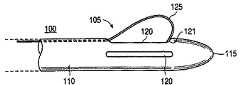
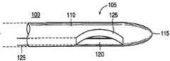
図1A、図1Bおよび図1Cは本発明に係る切開生検装置100の遠位の領域105の一実施例を示している。図1A、図1Bおよび図1Cをそれぞれ参照すると、切開生検装置100の遠位の領域105は通常先細の遠位の先端部115を有する全体的にチューブ状の部材110を備えている。遠位の先端部115は、例えば胸部組織、肺組織、肝臓組織等の軟性組織内に進入するよう構成される。従って、切開生検装置100の遠位の先端115および遠位の領域105は、進入する軟性組織に対して滑らかかつ比較的非外傷性の形状を形成することが好適である。他方、先端部115は、鋭く尖っているか、および/または組織の切開を行うためのエネルギー源(図示されていない)を備えることもできる。チューブ状部材110は、例えば、固形かつ硬質なプラスチック、またはステンレス鋼で形成することができる。チューブ状部材110は、安全性および機能性の理由から、一度使って使い捨てとすることが好適である。
【0036】
カッターウィンドウ120がチューブ状部材110内に配置される。カッターウィンドウ120は、例えばチューブ状部材110内において浅い溝形状とすることができる。図1Cにもっと良く示されているように、カッターウィンドウ120は、チューブ状部材110内において、浅くかつ実質的に長方形の溝とするか、または例えばI字形状の溝とすることができる。切開生検装置125は、切断工具125等の作用要素を備えている。切断工具125の遠位の端部は、チューブ状部材110の遠位の先端部115近傍に装着されている。例えば、切断工具125の遠位の端部はカッターウィンドウ120の最も遠位の点121に装着することができる。しかしながら、切断工具125は、遠位の領域105内の他の点に装着することもできる。切断工具125の遠位の部分はカッターウィンドウ120を通じて露出している。切断工具125の残りの部分は、全体的にチューブ状の部材110内の内部ガイドまたは内腔130内に配置されている。内部ガイド130は、切断工具125の動作を拘束するとともに切断工具125がチューブ状部材110の縦軸に平行にスライドすることを可能にする。次に図2Cを参照すると、切断工具125の近位の部分225はチューブ状部材110の近位の端部215近傍の内腔130から露出している。切断工具125の近位の端部は、例えば押しまたは回転ノブ226を備えることができる。この押しまたは回転ノブ226は、切開生検装置100の操作者が切断工具125を選択的に遠位の方向(医師から離れて遠位の先端部115の方向)に推動するか、または切断工具125を近位の方向(遠位の先端部115から離れて医師の方向)へ引き戻すことを可能にする。切断工具125の動作制御を補助するため、切断工具は、図2Cに矢印227で示されているように、近位の方向にバイアスすることが好適である。このバイアスは、チューブ状部材110の近位の端部215またはその近傍および切断工具125の近位の端部225に装着されるバネ228によって有効化される。この方式において、切断工具125のデフォルト構成は引き戻し位置であり、この際切断工具125はチューブ状部材110内のカッターウィンドウ120内に実質的に平らに延在している。
【0037】
医師が押しまたは回転ノブ226あるいは同様な装置を押圧して切断工具125を遠位の方向に推動すると、切断工具はチューブ状部材110内の内部ガイド130に沿ってスライドする。切断工具125の遠位の端部がチューブ状部材110の遠位の端部またはカッターウィンドウ120の最も遠位の点121に装着される際、カッターウィンドウ120を通じて露出する部分は外側に曲折する傾向があり、図1Bに示されるようにカッターウィンドウ120の外側に伸出する。カッターウィンドウ120からの伸出および曲がり角度は、押しまたは回転ノブ226を適正に操作することによって医師が制御することができる。従って、伸出および角度の範囲は可能性としては無限であり、医師が押しまたは回転ノブ226を精密に推動または引張することによって切断工具125を制御することによってのみ制限される。従って、切断工具の伸出の度合いならびに曲がりの角度は、チューブ状部材110の内部ガイド130内において切断工具を選択的にスライドさせることによって制御される。
【0038】
曲げられた部分の形状および切断工具125の遠位の部分が外側に曲折するゆとりは、切断工具125の物理的特性を変化させることによって変更することができる。切断工具は、弾力性があり容易に変形可能で圧力が作用してない際は元の非バイアス状態に復元する材料で形成することが好適である。例えば、切断工具125にはニッケルチタン合金を使用することができ、これにより切断工具125が形状記憶特性を備えることができる。曲げられ伸出した状態(図2)における切断工具125の形状は、例えば、切断工具のカッターウィンドウ120を介して突出する部分の厚さを調整することによって変更することができる。切断工具125の局部的に厚い部分は局部的に薄い部分より曲がりにくいものとなる。従って、例えば切断工具125の厚さを適正に変化させることにより、その曲率を制御することができる。
【0039】
図1A、図1Bおよび図1Cに示されるように、押しまたは回転ノブ226(または同様な機能をする装置)を押圧することにより切断工具125を外側に曲げてチューブ状部材110のカッターウィンドウ120から伸出させることができる(図1B)。同様に押しまたは回転ノブ226(または同様な機能をする装置)を引張することにより、切断工具125をカッターウィンドウ120内に引き戻し、チューブ状部材110の外側表面と実質的に同じ高さとなる形状(図1A参照)にすることができる。この形状において、チューブ状部材110は胸部、肺、肝臓、その他の柔軟組織内に容易に進入することができる。
【0040】
動作時において、外科医は患者の胸部等の皮膚に切開部を形成する。切開生検装置100は胸部組織内に直接挿入され、または伸縮性被覆部材(図13の参照符号495参照)が切開部に挿入されてその後伸張され、切開生検装置100はその中に挿入される。いずれにしても、切開生検装置は、胸部組織内の、例えば患部近傍または切開が実施される目標部分の近傍に挿入される。切開生検装置100を軟性組織内に挿入している間、切断工具125はその引き戻された状態にあり、そのカッターウィンドウ125から伸出する部分は実質的に平らな形状となる。従って、この状態において、切開装置100は、周りの組織に対して平滑かつ先細の形状を示す。装置100が軟性組織内において適正な位置にあると判断されると、装置はその縦軸回りに回転される。この回転は手動で行うか、または装置100の近位の領域に設置されたモータによって実施することができる。装置100が回転する際、外科医は切断工具125を外側に曲げカッターウィンドウ120から伸出させる。曲がり角度および伸出の度合いは、少なくともカッターウィンドウ120と切断工具125の間に患部(胸部内の目標とする微細石灰化等)を含むために充分なものとする。切断工具125は、装置100が回転される際に組織を切断し、これによって患部を周りの胸部組織塊から切除する。胸部組織内で少なくとも一回転することにより、切断工具125は胸部組織を一回り量分走査し、この量を元の組織塊から切除する。この一回り分の量は少なくとも目標とする患部に相当する。元の組織塊から切除する一回り分の量は、目標の患部だけでなく患部の周りの健康な組織からの縁分を含めることが好適である。切断工具125の曲がり角度および伸張の度合いは、切開生検装置100の所定の回転内で変化させることができる。この方式により、元の組織塊から切除する組織の量とともに切除片の形状を精密に制御することができる。
【0041】
患部および好適には患部の周りの健康な組織の縁部が切断された後、切断された組織は元の組織塊から除去される。切断された組織の除去はいくつかの方法によって実施することができ、それは切開生検装置100を元の組織塊から引き抜くことを含んでいる。他方、切断された組織の採取は以下に記す装置および方法によって実行することもできる。
【0042】
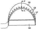
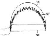
図1Cに示されているように、切断工具125は薄いリボンとして構成される。図1Cに示されたリボン125は、組織および時には繊維や石灰化軟骨を切断するためにその前エッジ部を鋭利に研ぐことが好適である。切断工具125の前エッジ部は、装置100が回転する際に、切断する組織に最初に接触する。この鋭利に研がれたエッジは図4において参照符号127に示されている。この種のリボン切断工具125の幅は、切断工具125が近位の方向に引き戻される際に工具が収容されるカッターウィンドウ120の幅より小さいことが好適である。
【0043】
図8には切断工具の別の実施例が示されている。切断工具125が低速で組織を切断する際の前進抵抗を低下させるため、カッターウィンドウ120を介して露出する前エッジ部は複数の歯127を有する鋸歯状とすることができる。さらに、複数の歯127の前エッジ部は鋭利に研がれたエッジを備えることができる。この方式により、切開装置100が回転する際、まず最も前の歯127のみが切断する組織と接触し、この結果回転する切断刃125の圧力が付加される組織の面積が縮小される。従って、図8の切断刃125は、切開生検装置100が軟性組織塊内において回転される際、付加されるトルクを最小限にしながらも比較的高密度および繊維質の組織を極めて効果的に切断することができる。
【0044】
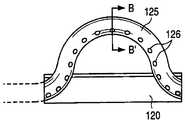
図4および図5を参照すると、切断工具125はさらにこの長さ全体または一部にわたって延在する内腔128を備えることができる。切断工具125は、さらに、その遠位の領域にカッターウィンドウ120を介して露出する複数の貫通孔126を備えることができる。これらの複数の貫通孔126は、内腔128と液体交換結合にある。使用時において、内腔128は切開生検装置100の近位の部分において液体タンクに結合されている。この液体タンクは装置100に対して内部または外部から装着することができ、切断工具125の遠位の部分に例えば(リドカイン等の)麻酔剤および/または抗生剤溶液を付加する。この方式により、この種の麻酔剤および/または抗生剤溶液(または他の液体)は、切断工具が回転する際にその周りの組織に正確に付加される。例えば、正確に計量された麻酔剤を最も効果的な部分に付加することができる。この麻酔剤が必要な場所のみに付加されるため、その効果は即効的となり、患者は本発明に係る切開生検装置100が胸部またはその他の軟性組織内を回転する際に最小の痛みしか感じない。図5は図4の線AA'に沿った切断工具125の断面図である。
【0045】
図4および図5に示された切断工具125の構造および材料の選択には注意が必要である。すなわち、選択される構造および材料は、切断工具125が曲折して装置100のカッターウィンドウ120から伸出することを可能にするものでなければならないが、切断工具125が内腔128を備えている場合その内部を通流する液体の流れを妨害するかあるいは実質的に破壊しないことが求められる。例えば、切断工具125は、ニッケルチタン等の形状記憶合金で形成するか、および/または切断工具125の近位の部分を他の部分に比して比較的厚く形成することができる。
【0046】
図15および図16に切断工具125の別の実施例が示されている。これらに示されているように、切断工具125は薄い鋼板または形状記憶合金のシートによって形成されている。このシートは複数の貫通孔126を備えることができ、これを介して麻酔剤またはその他の液体を浸透させる。シート上には、貫通孔126とともに配列された小さなチューブ540を設置することができる。シートは矢印530によって示された方向に折りたたむことができ、従ってチューブ540は折りたたまれた二つのシート面の間に固定される。シートのエッジ550は互いに密封され、その中に液体を充満させる。例えば、シートの面550は互いに溶接するか、またはその他の金属加工技術者により周知の方法で固定される。貫通孔126間のエッジ560は鋭利に研磨することができ、これによって切断工具125が軟性組織を効果的に切断する。図16に示されているように、チューブ540は、切断工具125に麻酔剤またはその他の液体を伝送し、これは、切断工具125の切断エッジが作用する、必要な個所に精密な量を伝送し、これによって患者は即時に麻酔をかけられ必要な麻酔剤の量を削減する。チューブ540の近位の端部は、麻酔剤タンク(図示されていない)および/または麻酔剤ポンプ(同じく図示されていない)と液体交換結合させている。
【0047】
他方、切断工具125は、図6および図7の参照符号125に示されているように細いワイヤを備えることができる。この場合、外部の高周波(以下RF)電源240(図2Cに参照符号240で示されている)が図6の切断工具125に接続された2つのバイポーラ電極(図示されていない)を介して切断工具125にRFエネルギーを供給する。本発明の概念において別のエネルギー源を使用することもでき、以下において説明の目的でRF電源を使用する。RF電源240によって供給されたRF電力は、切断工具125に付加される電力を選択的に変化させることにより、図6の切断工具125が電気手術切断装置および/または電気凝結装置として作用することを可能にする。この種の電気手術切断装置125に適したジェネレータは、当業者において周知である。それらの好適なジェネレータの一例は、ミネソタ州ブルックリンセンターのエベレストメディカル社によって1990年2月27日に発行された米国特許第4903696号に記載されており、これはここにおいて全体的に参照に組み入れてある。図4および図5に示された切断工具125と同様に、図6ないし図7に示された切断工具125も内腔128および複数の貫通孔126を備えており、これによって装置100が回転して切断工具125が軟性組織を切断する際に周りの組織に麻酔剤またはその他の液体を付加する。
【0048】
前述したように、本発明に係る切開生検装置100は、全体的にチューブ状の部材110の回転に基づいて軟性組織を切断する際に回転容積分(対称形である必要はない)を切除する。この切除された組織片は、伸縮性の組織固定装置によって安定化することができ、この固定装置は、切除した組織標本を胸部から採取する際にも機能する。固定装置は、例えば、吸引装置またはその他の実質的に強固な固定装置を備えることができ、これによって組織標本を固定する。他方、切断された組織標本は、図2Aおよび図2Bに参照符号260で示される組織収集装置内に収容することができる。組織収集装置260は、チューブ状部材110に外側から接合されるとともに、好適には切断工具125の前縁部にも接合される。組織収集装置260は、薄くかつ柔軟なプラスチック薄膜からなる袋形状に構成することが好適である。袋形状の収集装置260の開放部分は開放部分120と同じ大きさを持つことが好適であり、またチューブ状部材110ならびに切断工具125の前縁部に接合することが好適である。この方式により、袋形状の収集装置260の開放部分または“口“は、切断工具125の曲がりおよび引き戻しに伴ってそれぞれ開閉する。従って、袋形状の収集装置260の“口”は、切断工具125が曲げられてカッターウィンドウ120の外へ伸出している際に開放され、切断工具がカッターウィンドウ120内に引き戻されている際に閉鎖され、これは収集装置の2つの縁部(一つはチューブ状部材110のカッターウィンドウ120の近傍に接合され、もう一つは切断工具125の前縁部に接合される)が互いに圧接されるからである。
【0049】
従って、切開生検装置100が組織内に挿入され回転された際、切断工具125は曲げられカッターウィンドウ120から伸出し、これに接触する組織を切断する。装置100が回転して切断する際、切断工具125とチューブ状部材110との間の組織は収集装置の中に進行する傾向がある。切断工具125が曲げられ伸出している状態において、袋形状の収集装置260の“口“または開口部分もこれに従って開放され、切断された組織を収集することが可能となる。チューブ状部材110の回転が実施されると、切断工具125が引き戻されてカッターウィンドウ120内に収容され、図2Bに示されるように、チューブ状部材110の外表面と実質的に同じ高さとなる。この状態において、収集装置260は閉鎖されており、これによって切断された組織を保持する。その後、装置100は、例えば胸部等の元の組織塊から安全に引き戻される。切断された標本が残留する組織塊から物理的に除去される際、異常のある可能性がある細胞片を周りの組織に散逸させる危険性が大幅に減少する。本発明に係る切開装置100が切断工具125の曲がりおよび伸出の度合いを適宜に選択することにより外科医が目標患部の周りの健康な組織から適正な縁部を切除することを可能にするため、さらに危険性が減少する。この方式において、患部の結合性は破壊されず、これによって組織構造が完全に保存される。
【0050】
収集装置260は薄くかつ柔軟性のある薄膜から形成することが好適であるため、軟性組織内に挿入する間、チューブ状部材110の外部表面に対して実質的に平らか、あるいはカッターウィンドウ120内に僅かに窪んで収容することができる。収集装置260は、従って、処置中または処置前に患者の皮膚に形成された切開部内に装置100が挿入される際に、多少の追加的引きずりおよび抵抗をもたらす。組織収集装置260に適した材料は、例えばプラスチックおよびナイロンである。組織収集装置260をチューブ状部材110ならびに切断工具125に接着するために任意の強力な接着剤を使用することができる。本発明の概念から逸脱することなく、収集装置260を固定するためにその他の方法を使用することもできる。同様に、組織収集装置260は、本発明の精神から逸脱することなく、ここに挙げられた以外の材料で構成することができる。好適には、組織収集装置の形状およびサイズは切開生検装置100が組織内で回転した際に抵抗を最小化するよう選択される。例えば、組織収集装置260は、切断された組織標本を収容するために充分な最小限の大きさとすることが好適である。
【0051】
本発明に係る切開生検装置100は、胸部またはその他の臓器内の患部に近接して正確に配置されることが好適である。このため、本発明によれば、外科医が処置中に軟性組織の内部構造を略リアルタイムまたはリアルタイム情報として得ることが可能となる。再度図1および図2Cを参照すると、本発明はチューブ状部材110の遠位の部分上に装着された変換器270を備えることができる。この変換器270は、切開生検装置100が軟性組織内を回転する際に切断工具125によって切断する組織を画像化するよう構成される。従って、変換器270は、切断すべき組織に関する情報を発信することが好適であり、すなわち、チューブ状部材110がその縦軸回りに回転する際に切断工具125と接触する前の組織に関する情報を発信する。この方式において、切開生検装置100の回転速度は極めて低速であるため(回転は手動で実施するか、またはチューブ状部材110内に装着されたモータによって実施することができる)、外科医は変換器によって発信された情報を分析し、この情報に基づいて切断工具125の曲げ角度および伸出の度合いを調整することができる。例えば、装置100が目標とする患部の近くに位置して回転する際、変換器270はこの患部が切断工具125と接触する前に患部の存在と位置を検出する。患部が変換器270によって検出された後、外科医は押しまたは回転ノブ226または同等な装置を押圧して切断工具を曲げるとともにカッターウィンドウ120から伸出させる。患部(および好適には適宜に健康な組織の縁部を含む)は元の塊から切断され、例えば組織収集装置260内に任意に収集される。変換器270により、チューブ状部材が回転して切断工具125が患部を通過したしたことが示された際、切断工具125はカッターウィンドウ120内に引き戻すことができる。この切断は、元の組織塊内において近リアルタイムまたはリアルタイムでサイズおよび形状を特殊に設定して行うことができ、これによって外科医が必要な組織を全て切断し、しかも目的を達成するために必要な組織のみを切断することを可能にする。
【0052】
好適には、変換器270は、チューブ状部材110の外表面に対して実質的に同じ高さで装着された超音波センサとすることが好適である。超音波センサ270は、図2Cにおいて参照符号250で示されている少なくとも一つのデータ処理および表示装置に導電線等の交信チャネルを介して電気的に接続することが好適である。データ処理および表示装置は、外科医が切断工具125によって切断される組織の内部構造を黙示することを可能にする。これにより、外科医が処理の最中に組織の内部構造のグラフィック表示を見ることができるばかりでなく、例えば、変換器270が付勢されている際に切断工具をカッターウィンドウ内に引き戻し組織内でチューブ状装置を回転させることにより、全ての患部または患部群を適正に切除したかどうかを外科医が確認することが可能になる。従って、別の視点から見ると、本発明は、例えば参照符号125で示された切断工具を必要に応じて備えることができる超音波画像装置でもある。
【0053】
動作時において、(超音波)変換器が切断工具125等の作用要素の前方の組織内の平面(図3Aに参照符号280で示されている)を走査する。超音波変換器270の動作特性を選択する際、外科医は要求される解像度(すなわち識別可能な最小単位)と、組織内における超音波の進入度ならびに発信される超音波の強度との間でバランスをとる必要がある。一般的に、周波数が高い程解像度が高くなる。しかしながら、高い周波数は低い周波数の超音波ほど深く組織内に進入しない。好適には、超音波変換器270は、約5MHzないし約20MHzで調整される。さらに好適には、超音波変換器270は、約7.5MHzないし約20MHzで調整される。例えば、本発明に係る切開生検装置100が女性の胸部に適用される場合、超音波変換器は、約10MHzないし約13MHzで調整することができる。
【0054】
内部組織構造を切断工具125によって切断する前に効果的に画像化するため、例えば、変換器270はチューブ状部材110内において切断工具125から離間して配置する必要がある。図9を参照すると、変換器270は、チューブ状部材内において切断工具125に対して角度αをもって配置される。この角度αは、チューブ状部材110が回転する際に変換器270によって生成される情報に応答して作用要素(例えば切断工具125)の動作を効果的に制御するために充分な角度より大きなものとすることが好適である。従って、この角度αは、少なくともチューブ状部材110にかかる回転速度と、および外科医が変換器によって発信された情報を分析してこの情報に応答して切断工具125を効果的に制御するために必要とする時間とに依存する。角度αは約180°よりも小さいことが好適である。
【0055】
参照符号270で示されている組織内超音波変換器と結合して使用する場合、本発明に係る切開生検装置100は切断工具125に代えてまたはこれに加えて多様な作用要素を使用することができる。この種の作用要素は、例えば、研磨装置、往復型切断装置、電気手術装置、または振動装置等である。
【0056】
胸部内の患部の場合、画像化および侵入式処置の前に胸部を安定化することが効果的である。この安定化は通常胸部を押し潰し組織を圧迫する圧縮板を使用して実施される。この種の圧縮は、効果的な画像を撮影するためにマンモグラフィに使用するX線照射を行うために必要である。この種の圧縮は本発明には必要でないと考えられるが、胸部の安定化は必要である。この目的のため、1998年 9月22日に出願された発明の名称が「胸部安定化装置及び方法」である通常通り付与された米国特許出願第09/158,215号と、1998年 11月25日に出願された発明の名称が「胸部安定化装置及び画像化並びにそれを用いた新規な方法」である通常通り付与された米国特許出願第09/200,661号に記載されている安定化装置が有効であり得、これらの開示はいずれも本明細書に全体として組み入れてある。
【0057】
次に、図3A、図3Bおよび図3Cを参照すると、これらには本発明に係る切開生検方法の一実施例が示されている。図3A〜図3Cは胸部手術における本発明の一実施例を示しているが、本発明に係る方法は、当業者においては、僅かな変更を行うことにより例えば肺、甲状腺または肝臓組織等他の軟性組織に適用可能である。
【0058】
まず図3Aを参照すると、胸部310内において、好適には乳頭周辺の領域に、小さな切開部331が形成される。好適には、例えば前述の米国特許出願第09/158,215号あるいは第09/200,661号に記載された装置を使用して胸部を安定化させる。軟性組織の外側に残留する装置100の部分は、例えば安定した動作および正確な制御を可能にするために装置を枠構造に固定する装着手段を備えることができる。小さな切開部は、乳頭320の周辺の乳輪330の境界上に形成することが好適であり、これにより胸部310の側部の皮膚を切開するより美容上有利な傷となる。患部の大きさおよび挿入される切開生検装置100の大きさに依存して、伸縮性の被覆部材(その一例は図13の参照符号495に示されている)を胸部組織内に挿入することができる。いずれにしても、切開生検装置100は胸部組織内に挿入されて患部300の近傍に配置され、この患部は例えば微細石灰化またはその他の異常な患部である。所定位置に配置されると、例えば図3Aに示された方向に装置100は回転される。軟性組織の外部に残留する装置100の部分は、軟性組織内に進入するよう設計された部分に比べて大きな直径を有することができる。これは装置100を手動で回転する際に有効である。図3Aに示された状態において、切断工具125はカッターウィンドウ120内に引き戻されており、組織収集装置260が存在する場合、これはチューブ状部材110の外表面に対して実質的に平らになる。装置100はその縦軸回りで回転し、変換器270が付勢され、これによって得られた情報は、例えば、図2Cに示された表示装置250に伝送される。患部300が見えると、外科医はそのサイズ、形状および位置を測定し、変換器270によって受信されディスプレイ250上に表示された情報に基づいて切断工具125等の作用要素の曲がりおよび伸出を制御する。図3Bには、患部300が画像化され、外科医が患部を周囲の胸部組織から切断するために切断工具125を伸出させた状態が示されている。切断された組織は、装置100が回転する際に組織収集装置260内に受容かつ集積することができる。麻酔および/または抗生剤(またはその他の)溶液は貫通孔126を介して作用組織に直接注入することができ(図2A,図2Bおよび図4〜7に最もよく示されている)、処置中の苦痛が大幅に減少する。
【0059】
患部ならびに必要な健康細胞の縁部が元の胸部組織塊から切断された後、切断工具125はカッターウィンドウ120内に引き戻される。これにより、組織収集装置260が存在する場合これが閉鎖され、図3Cに示されているように、装置100全体を胸部から矢印350の方向に引き戻すことが可能となる。組織収集装置260が存在する場合、患部300は組織収集装置260の薄膜によって周囲の組織から隔離され、従って異常な細胞片を周囲の胸部組織に拡散させる危険性が最小化される。さらに、採取された患部300の組織構造が実質的に保存され、従って胸部から切除した組織片全体について正確な組織病理解析を実施することが可能となる。従って、この組織が被る圧縮は、圧縮されていない胸部組織内にある装置100がその進入経路から引き戻されることによるもののみと考えられる。その後、切開装置100が胸部310から除去される場合、押しまたは回転ノブ226を付勢して切断工具125が曲げられて伸出し、これによって切断された組織が組織収集装置260から採取され検査される。組織収集装置が存在しない場合、胸部組織から切断された患部を抽出するために従来の吸引装置を使用することができる。電気手術切断工具125が存在する場合、これに付加されるRF電源またはその他の動力源を適宜に調整することにより出血を制御することができ、出血を抑えるために組織を焼灼して血液を凝結する。
【0060】
処置の後、胸部内の患部が存在した場所に小さな空洞が残留する。しかしながら、胸部に対して圧縮が加えられていないため、従来の技術とは異なって、処置後に胸部の伸張は発生しない。従って、空洞ならびに装置の進入および退出口は可能な限り小さいままとなり、合併症はあまり発生せず、組織の損傷も少なく、美容的にも改善される。
【0061】
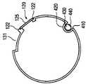
図10,図11および図12に示される本発明の別の実施例においては、変換器270は取り外し可能な変換器コア400によって置換される。取り外し可能な変換器コア400は能動要素440を備えており、これは組織内部の画像化を実施するとともに参照符号460で示された交信チャネルを介して表示装置(図14に示されている)に情報を伝達するよう構成されている。交信チャネル460は、無線とするか、あるいは光ファイバおよび/または電気ケーブルから構成することができる。能動要素440は、内蔵電池(図示されていない)または参照符号480で示された電力源から電力を取り込むことができる。能動要素440は、超音波変換器から構成することができる。超音波変換器に代えてまたはこれに加えて他の種類の変換器を使用することもできる。取り外し可能な変換器コア400は、全体的にチューブ状のシャフト430を備えることが好適である。近位の部分450は変換器コア400の近位の部分の近傍に位置している。
【0062】
取り外し可能な変換器コア400を収容するため、図10の切開装置100は内腔420を備えており、これに変換器コア400を挿入することができる。切開装置100は、安全性および機能性の理由から、一回使用して廃棄することが好適である。しかしながら、取り外し可能な変換器コア400は、使い捨てとするかまたは所定の回数繰り返し使用可能とすることができる。変換器コア400の能動要素440が切断する組織およびその周囲の組織を画像化することを可能にするため、切開装置100の全体的にチューブ状の部材110は変換器ウィンドウ410を備えている。取り外し可能な変換器コア400が内腔420に挿入される際、コア400の近位の部分450は装置100の近位の端部に嵌合してロックされることが好適である。ロック状態にある際、変換器コア400の能動要素440は、変換器ウィンドウ410に対して整列するとともにこれに対接し、これによって能動要素440が患部およびその周囲の組織を画像化することが可能となる。チューブ状部材110の患者の軟性組織中への挿入を容易にするため、最も遠位の先端それ自体は、引用番号116にて示した、図2C及び14中に240として示されるRF源によりエネルギーを与えられ得る(単極又は両極式の)RF電気手術要素又はワイヤを含み得る。
【0063】
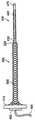
図11には、本発明に係る取り外し可能なコア400の一実施例が示されている。取り外し可能なコア400は切開装置100から独立して使用することが好適であるため、取り外し可能なコア400は先細となった遠位の先端部470を備えており、これによって軟性組織内に容易に進入する。さらに、その薄い形状により、外科医が取り外し可能なコア400を組織を過度に損傷するかまたは大きな傷を形成することなく軟性組織内に挿入することが可能となる。取り外し可能なコア400は、外科医が組織内において切断する患部を正確に位置判定することを可能にする。例えば、取り外し可能なコア400の能動要素440は、センサ270と同様な特性を有する超音波変換器から構成することができ、さらに単一または表面超音波センサに加えて使用することにより患部を極めて高精度に位置判定することができる。
【0064】
図12には、図10の切開装置100の線AA'に沿った断面図が示されている。図12に示されているように、切断工具125は変換器ウィンドウ120を介して露出している。ウィンドウ120は、図12に示されているように、切断工具125が外側に伸出して曲がっている際にこれを支持および誘導する支持ガイド122を備えることができる。組織収集装置260は、簡略化のため図10または図12には示されていない。しかしながら、前述した切断および収集動作の後に組織収集装置260内に集積された切断組織標本の採取物を収容するために、チューブ状部材110は窪み部分131を備えることができる。窪み部分は、切開装置が軟性組織の塊から除去された際に、組織収集装置260内に収集(収納)された組織標本のための空間を提供する。この方式により、組織収集装置260内に収集された組織標本は、この組織標本を切り取った元の柔軟組織塊から切開装置100を引き抜いた反動によって、標本組織が実質的に平坦な切開装置の外表面から飛び出すことが防止される。内腔420は、取り外し可能なコア400がこの内部にスライドして、能動要素440が変換器ウィンドウ410に面して適正な位置をとることを可能にする。
【0065】
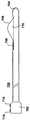
図13には伸縮性被覆部材495内に挿入された取り外し可能なコア400が示されている。伸縮性の被覆部材510は近位の基礎部分510を備えている。近位の基礎部分510には、全体的にシリンダ形状の、例えばプラスチックまたはナイロン製のメッシュ部材500が装着されている。メッシュ部材500は、その遠位の端部においていくらか先細となっており、これによって伸縮性メッシュ部材500と取り外し可能コア装置400との間でスムーズな遷移がなされる。コア400の近位の部分は、伸縮性被覆部材495の近位の基礎部分510にスナップ結合し、これによって確実かつ取り外し可能に固定される。図13に示されているように、伸縮性メッシュ部材500は、取り外し可能なコア400を挿入するためにちょうど充分であるように形成される。実用上において、伸縮性被覆部材495および取り外し可能なコア400の組み立て体は、軟性組織内に同時に挿入され、これによって外科医がいくらか大きな直径を有する切開装置100を挿入する前に患部を画像化することができる。その後、外科医は伸縮性被覆部材495から取り外し可能なコア400を引き抜き、伸縮性の被覆部材495は胸部等の組織内に残留する。
【0066】
図14には、本発明に係る柔軟組織切開装置600の別の実施例が示されている。図14に示された状態において、取り外し可能なコア400は切開装置100内に挿入および固定され、従って能動要素440が変換器ウィンドウ410から外に指向する。図10には、簡略化のため組織収集装置260は示されていない。図14には、切開装置100が伸縮性被覆部材495に挿入された状態で示されている。従って、図14に示されるように、切開装置100はメッシュ部材500内に挿入されその遠位の端部520に到達しており、切開装置100の遠位の部分は切断工具125および変換器ウィンドウ410とともにこの中を延在している。図14において、メッシュ部材500は、切開装置100の直径を収容できるように伸張している。切開装置100の近位の部分は、伸縮性被覆495の基礎部分から延在している。このことにより、外科医が押しまたは回転ノブ226(図14に示された回転ノブ226)を手動で操作することが可能になる。組み立て体600には、多数の周辺装置を接続することができる。それらの例としては、例えば超音波変換器の電源となり得るコア動力源480、コア400の能動要素440によって画像化された内部組織情報を表示するための一つまたは複数のデータ処理および表示装置250、吸引手段490、切断工具動力源(例えば可変RFエネルギー源)、および/またはその他の装置590である。吸引装置490は内腔を介してウィンドウ120に吸引力を提供し、切断工具125による切断を実施する。
【0067】
切開装置組み立て体600は、一体的に回転するか、または切開装置100を伸縮性被覆部材495から独立して回転することができ、この際これら2つの間の摩擦に対応して回転する。好適には、図14に示されるように、切開装置100は伸縮性被覆部材495から除去可能であり、この際伸縮性の被覆部材495は軟性組織内に残留する。この方式により、切開装置100を被覆部材495から引き抜いた後、被覆部材495は軟性組織内に残留し、この中に他の器具を挿入することが可能となる。例えば、切開処理の終了後に取り外し可能なコア400を伸縮性被覆部材495内の切断部分に再度挿入することができる。その後、外科医はコア400の能動要素440を付勢し、これにより切断部を画像化して患部が完全に軟性組織塊から切除されたかどうかを確認することができる。これを実施するために、外科医は患部を示すディスプレイを監視しながら伸縮性被覆部材495の中で取り外し可能コア400を回転させる。何も発見されなかった場合、コア400を被覆部材495から引き抜き、さらに被覆部材を組織塊から引き抜いて、組み立て体を挿入する前に形成した切開部分を修復する。他方、外科医は、伸縮性被覆部材495とコア400を同時に除去することを選択することもできる。
【0068】
図17には、本発明に係る切開生検方法の一実施例が示されている。図17において、患部が切除される元となる軟性組織は胸部の組織であり、取り外し可能なコア400の能動要素440は超音波変換器であると仮定してある。他の組み合わせも可能であり、本発明は胸部組織ならびに超音波に係る適用に限定するものではない。図17において、取り外し可能なコア400および能動要素440は、まとめて“超音波コア”と省略されている。さらに、図17に示されている工程は本発明に係る方法の一実施例を概略的に示したものであることが理解されよう。従って、本発明の視点から逸脱することなく、図17の各工程の間にその他の追加的な工程を挿入するか、または他の工程によっていくつかの工程を置き換えることが可能である。
【0069】
この方法は工程S0からスタートする。工程S1において、例えばスタンダードまたは走触表面超音波によって、胸部内の患部が大まかに目標設定される。工程S1において、胸部内における大まかな患部の位置が得られる。外科医は、患部の大まかな位置を検出した後、その位置を超音波ディスプレイおよび/または胸部の表面に例えば“X”としてマークすることができる。胸部は工程S2において安定化される。好適には、通常通り処理され同時係属中である前述の参照米国特許出願第09/158,215号あるいは第09/200,661号に記述されているように、胸部は圧縮されないかまたは僅かに伸張された状態で安定化される。女性の別の方の乳房は反対側胸部安定化装置内に固定することが好適であり、これは処置中に女性を固定するよう作用する。例えば一つの超音波ポートを胸部のマーク部分に合わせることにより、胸部固定装置の超音波ポートの一つが患部に整合する。次に、前述した出願に記載されているように、胸部安定化装置に吸引が付加され、適正に方向設定された表面超音波装置が安定化装置の超音波ポートに固定される。しかしながら、本発明の概念から逸脱することなく、その他の胸部安定化手段を使用することができる。
【0070】
工程S3において、胸部上の進入部分が選択される。乳輪周辺の部分を切開部分として選択することが好適であり、これは乳輪周囲の傷は他の胸部露出部分の傷に比べて目立たないともにその他の解剖学上の理由からである。切開部分は、皮膚と皮下の両方について麻酔される。工程S3においても、選択した切開場所において小さな切開部が形成される。切開部は、伸縮性の被覆部材495およびこの中に挿入された取り外し可能なコア400を収容するために充分な大きさとすることが好適である。工程S4において、伸縮性の被覆部材495は、これに挿入された取り外し可能なコアと共に工程S3において形成された切開部に挿入される。表面超音波誘導によって、例えば、被覆部材495/コア400組み立て体が患部の近くに誘導される。被覆部材495/コア400組み立て体は、目標の患部近傍に正確に配置され、本発明の方法は工程S5に進行する。被覆部材495/コア400組み立て体が目標患部近傍に正しく配置されない場合、これらが目標患部近傍に正しく配置されるまで前述の工程のいくつかまたは全てが繰り返される。
【0071】
ここで、外科医が満足できるように工程S4が完了したと仮定すると、工程S5に示されるように、コア400は伸縮性の被覆部材495から引き抜かれ、伸縮性の被覆部材495は胸部内に残留する。工程S6において、取り外し可能なコア400は切開装置100のチューブ状部材の内腔420内に挿入されてそこで固定され、従って能動要素440(この場合、超音波変換器)は装置100の変換器ウィンドウ410に整合してそこから外を指向する。再び伸縮性の被覆部材495を胸部内に残して、切開装置100(その内部に固定されたコア400と共に)が伸縮性被覆部材495内を前進する。被覆部材495は胸部組織内で伸張しいくらか大きな直径を有する切開装置100を収容する。切開装置100は、被覆部材495の先細の遠位の端部520へ前進し、従って被覆部材495、切開装置100、および取り外し可能なコア400からなる組み立て体は、工程S7に示されるように、胸部組織内の目標患部に近接して位置する。
【0072】
工程S8において、表面超音波および/またはコア超音波を使用して、患部に近接する正しい位置にあるか、また、前述した組み立て体(図14)が正しい方向に回転しているかを確認する。コア400の能動要素440は特にこの作業のために適しており、切開装置100が組織内を回転するとともに、切断工具125が回転し得るように適切な位置にあり、曲げられるとともに外側に伸出して適正な健康な組織の縁部を伴って患部を周囲の組織から切断することが可能となる。従って、超音波変換器440が切開装置100に伴って回転する際に、切断工具125が切断する前に患部を画像化し、これによって外科医がディスプレイ上の組織画像の観察に基づいて切断工具を最適に配置することが可能となる。工程9において、外科医は麻酔注入を作動し、麻酔剤は、図4および図6に示されるように、切断工具125によって複数の貫通孔126を介して注入される。切断工具125が貫通孔126を備えていない場合、または外科医が切断工具125の回転中に組織を麻酔する必要がないと判断した場合は、工程S9がスキップされる。例えば、組織が予め麻酔されている場合である。少なくとも切開装置100が(その中に固定された取り外し可能なコア400とともに)回転する際に、例えば図2Cおよび図14に参照符号226で示された押しまたは回転ノブを使用して切断工具125が伸ばされ、これによって切断工具125は工程S10に示されるようにウィンドウ410から伸出して外側に曲げられる。切開装置100と伸縮性被覆部材495との間の摩擦に応じて(これはメッシュ部材500の材料とメッシュの形状に依存して自由に選択可能である)、被覆部材495は切開装置100とともに回転される。伸出および曲がりの度合いは、切開装置100が回転する際に、手動またはこれに結合されたモータユニット(図示されていない)を使用して、外科医が精密に制御することができる。切断工具が回転する際、切断された組織標本は、工程S11に示されるように、組織収集装置260(図2Aおよび図2B)内に収集(袋詰め)されることが好適である。血管は、切断工具125が回転して組織を切断する際、またその後に凝結することができる。工程12において、切開装置100が胸部内において少なくとも一回の回転を実施して回転容積分を少なくとも目標の患部および好適には患部の周囲の健康な組織の縁部を含めて切断した後、切開生検装置100および取り外し可能なコア400の組み立て体が被覆部材495から引き抜かれ、被覆部材495は胸部内に残留する。好適には、組織収集装置260およびこれが収容した組織標本は、全体的にチューブ状の部材110内の窪み部分131内に存在する。この方式により、充填された収集装置260は、チューブ状部材110の表面から突出しないか、または過度には突出せず、これによって集積された組織標本を切開装置100とともに容易に被覆部材495から引き抜くことができる。
【0073】
切開装置100を引き抜いた後、コア400を装置100から引き抜いて胸部に残留する被覆部材495内に再度挿入することができる。工程S13に示されているように、コア400は、切断個所まで前進して回転し、外科医は切断個所を画像化して患部全体が切除されたかどうかを確認することができる。被覆部材495内のコア400による切断個所の画像化により目標患部が切除されていないことが判明した場合、いくつかの上記工程を繰り返すことができる。全ての目標患部が除去されたと仮定すると、例えば乳輪周囲の部分の縫合によって切開部を復元することができる。この方法は工程S16において終了する。
【0074】
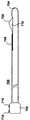
図11の取り外し可能なコア400は、切開装置100のチューブ状部材110に対して内部に備え付けられ得る取り外し可能なプローブだけではない(たとえば図10を参照)。確かに、図18は本発明の実施の形態による取り外し可能な切断プローブ700の上面図を示している。取り外し可能なプローブ700は近接部702及び末梢部704を含む。近接部702は切断工具伸張手段718を含み、末梢部704は上記のワイヤ又はリボンの切断工具のような切断工具706を含む。切断工具706はそのリーディングエッジを鋭利にされ得る。第一の取り外し可能なプローブ700は、好ましくは少なくとも部分的にチューブ状部材110の内部に備え付けられるよう設計されており、切断工具伸張手段718を稼動したとき切断工具706が選択的に第一のウィンドウ710の外側へ湾曲して出て内部へ引き戻されることを可能とする。第一のウィンドウ710は取り外し可能なプローブ700の表面内部に規定される。本発明の実施の形態によると、プローブ700内部に規定されたウィンドウ710がチューブ状部材110の表面内部に規定されたウィンドウ410(図10)に対面するように、取り外し可能な切断プローブ700はチューブ状部材110の内腔420内部に挿入され得る(又はチューブ状部材110内部のガイドに誘導され得る)。もう一つの方法として、チューブ状部材110は一つ又はそれ以上の図10の410で示されたような追加ウィンドウを規定してもよい。この場合、取り外し可能なプローブ700(及び図21乃至27Cに記載されたもの)はチューブ状部材110内部に挿入されてもよく、その結果ウィンドウ710はこれらの追加ウィンドウ(以下に総称して数字410により参照される)及び/又は図10及び12中のウィンドウ410のうちのひとつと対面する。
【0075】
本発明の実施の形態によると、切断工具706はRF切断工具を含んでもよい。この場合、RF切断工具及び取り外し可能な切断プローブ700は、図2C、14及び18中の240に示されるようなRF電源に接続され得る。RF切断工具は、たとえば、上記のように単極又は両極のいずれかのRF切断工具であってよい。
【0076】
取り外し可能な切断プローブ700はまた内部ガイド712を含み得(又は内腔を規定し得)、切断工具伸張手段718を稼動するとき切断工具706が取り外し可能な切断プローブ700内部にてスライドすることも可能とする。切断工具伸張手段718は図18乃至20中に親指で作動するダイヤルとして示される。しかしながら、切断工具706を改善し撤回したその他の手段も本発明の文脈範囲内で有利に使用され得る。また更なる実施の形態によると、取り外し可能な切断プローブ700の末梢部704はウィンドウ710内部に配置されたウィンドウスライド708を更に含んでもよく、近接端部702はウィンドウスライド伸張手段716を更に含んでもよい。ウィンドウスライド708はウィンドウスライド伸張手段716に結合し、取り外し可能な切断プローブ700内部にプローブ700の長辺に沿った内部ガイド又は内腔714により誘導される。本発明によると、ウィンドウスライド708は、ウィンドウスライド伸張手段716を稼動したとき選択的にウィンドウ710の一部を覆うように設計されている。ウィンドウスライド伸張手段716は図18乃至20に親指で作動するダイヤルとして示される。しかしながら、選択的にその部分を覆うためのウィンドウ710内部のウィンドウスライド708を伸張するいずれの手段も、当業者が認めるように、取り外し可能な切断プローブ700内部にて容易に実施され得る。機能的に、ウィンドウスライド708はウィンドウ710の一部を覆い、切断工具706が伸張し又は湾曲するためのウィンドウ710の幅を選択的に変化させる。
【0077】
取り外し可能な切断工具700の作用は図式的に図19及び20に示す。図19は、図18の取り外し可能な切断プローブ側面図であり、本発明の実施の形態によれば第一の位置の調節可能なウィンドウスライド708を示し、一方、図20は図18の取り外し可能な切断プローブの側面図であり、第二の位置の調節可能なウィンドウスライド708を示す。図19に示すように、ウィンドウスライド708はウィンドウ710の内部に引き付けられておらずそして図20でも同じである。その結果として、ウィンドウスライド708が他と比べてより引き付けられた図20に示されたような部分に存在するときに可能なより、図19の切断工具706はウィンドウ710のより広い部分を伸張可能である。たとえば、医者が、プローブ700が図19に描かれている形状のとき切断されるものとは異なりより小さな組織標本を切断したいと欲するとき、ウィンドウスライド708は更にウィンドウ710(図20)の内部に引き付けられ得る。
【0078】
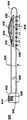
本発明の実施の形態によると、図21は取り外し可能な組織収集プローブ800の上面図である。その中に示すように、取り外し可能な組織収集プローブ800は近接部802及び末梢部804を含む。近接部802は組織収集装置伸張手段814を含み得、末梢部804は組織収集装置808、810を含み得る。図18乃至20の取り外し可能な切断プローブ700と同様、取り外し可能な組織収集プローブ800は少なくとも部分的にチューブ状部材110内部に備え付けられるよう設計され得、組織収集装置伸張手段814を稼動したとき組織収集装置808、810がウィンドウ410(又はチューブ状部材110の表面内部に規定された他のウィンドウ)の外側へ伸張し内部へ引き戻されることを可能とした。図18乃至20の稼動手段716,718と同様に、組織収集装置伸張手段814は親指用ダイヤル又は回転盤又はたとえばレバーのようなその他の好ましい組織収集装置808,810を伸張する手段として設計されてもよい。図21の上面図及び図22の詳細図に示すように、組織収集装置808,810はプローブ800のウィンドウ806から伸張し湾曲して出て、内部に引き戻されるよう設計され得たリボン又はワイヤ808を含み得る。ワイヤ又はリボン808に取り付けられたものは、たとえばポリエチレン又はポリエチレンテレフタレート(PET)のような非透過性又は透過性の部材810のフレキシブルな薄膜である。非透過性部材は組織標本を周囲の組織から隔離するために好ましい。そのような隔離は、癌の可能性のある細胞をプローブ及び/又は切開装置100の挿入跡に沿って分散させることを防止するために役に立つ。非透過性のフレキシブルな部材810はそれ自身からの流体及び細胞の漏出を防止し、切断した組織標本の分離を確実にする。フレキシブルな薄膜の部材810はそのような部材のロール814から分配され得、シート810の自由端はリボン又はワイヤ808に取り付けられている。この方法において、リボン又はワイヤ808はウィンドウ806の外側(チューブ状部材110における(対面する)類似のウィンドウの外側)に伸張し湾曲して出るので、ロール814は部材810を分配し得、そしてチューブ状部材110及び含まれているプローブ800を患者の軟性組織の内部で回転するので完全に又は部分的に組織標本を取り囲み収容する(図27A乃至27Cの参照番号1008参照)。もう一つの方法として、組織収集装置808,810は、例えば図2A及び2Bに示し開示したように設計され得る。組織収集装置伸張手段814が稼動している時、リボン又はワイヤ808は内腔又はプローブ800中に規定されたガイド812に沿ってスライドし、リボン又はワイヤ808をプローブ800中に規定されたウィンドウ806の外側へ湾曲させ伸張させ、それによってフレキシブルな部材810を展開し組織標本を収容する。これらの実施の形態では組織標本が病理学による最も望ましい組織構造分析のために一塊で分離してよい。図27A乃至27Cはさらに別の組織収集装置形態を、以下に開示のように示している。
【0079】
図23は図21の取り外し可能な組織収集プローブ800の側面図を示している、なお、図21は伸張した形態の組織収集装置808,810を示している。その中に示すように、組織収集装置伸張手段814は(操作法的に、例えば)組織収集プローブ800内部に規定されたウィンドウ806の外側へ組織収集装置808,810が湾曲するよう稼動する。このワイヤ又はリボン808の湾曲、又は伸張、は、部材810の薄膜が広げ、さもなければ展開させる。切開装置100のチューブ状部材110は回転するので、矢印816により示されている位置にて例えば、その中に含まれている組織収集プローブもまた回転する。組織収集装置伸張手段814は伸張(湾曲)するよう稼動し得るので、切断工具706がそうであったように、リボン又はワイヤ808が組織内部の実質的に同じ経路をたどらせる。このことは、リボン又はワイヤ808が単に切断工具706又は125により以前に作られた切開の経路をたどるので収集工程を容易化する。切開装置は回転するので、組織標本(すなわち病巣)は部材又はバック810のシートの内部に捕捉され、その結果患者から病理学的研究のため容易に摘出され得る。
【0080】
図24Aは、本発明の実施の形態による、取り外し可能な切断及び組織収集組み合わせプローブ900の上面図であり、図24Bは、図24Aの取り外し可能な切断及び組織収集組み合わせプローブ900の線AA’に沿って切断した部分的断面図である。図24Aに示されているように、切断と組織収集の組み合わせ取り外し可能なプローブ900は近接端部902及び末梢端部904を含んでいる。図24Aの実施の形態において、近接端部902は切断工具伸張手段908及び組織収集装置伸張手段906を含み得る。伸張手段906、908は親指で作動するダイヤル又は例えばレバーのような組織収集装置918及び/又は切断工具914を伸張するよう操作する如何なる装置として設計され得る。図24Bに示されるように、切断工具914及び組織収集装置918の一部を構成するワイヤ及び/又はリボンは伸張手段906、908からプローブ900の長辺に沿って伸張する。切断工具914及び組織収集装置918のワイヤ又はリボンはプローブ900内部をそれぞれガイド912及び910により誘導され得る。もう一つの方法として、図10に示されたチューブ状部材の内腔420に関し記載されているのと同じ方法で、切断工具914及び組織収集装置918のワイヤ又はリボンはプローブ900内部にその中に規定された一つ又はそれ以上の内腔により誘導され得る。切断工具914はRFエネルギーによりエネルギーを与えられ、切断工具914はその間にアークが生じるのを防止する十分な幅の(例えば)空隙920により組織収集装置918から分離され得る。
【0081】
図25は本発明のその他の実施の形態による切断及び組織収集組み合わせプローブ925の上面図である。図25の実施の形態は図24Aに示されたものと切断工具914が組織収集装置918から空隙によらずフレキシブルなプラスチック絶縁体のような断熱部材922によって分離している点で異なる。切断工具914がRF切断装置を含む場合、切断工具914は電気的に240のようなRF電源に結合される。図25に示されたプローブの近接端部902の形状もまた図24Aに示されたものと単一の伸張手段926が切断工具914及び組織収集装置918の両者を稼動させるよう設計されている点で異なり、切断工具914及び組織収集装置918は機械的にお互いに結合される。機械的に結合された切断工具914及び組織収集装置918を含むアセンブリは伸張手段926にプローブの長辺に沿って結合されており内部ガイド又は内腔924によりそこに沿って誘導される。
【0082】
図26は本発明の更なる実施の形態による取り外し可能な切断及び組織収集組合せプローブ950の側面図であって、切断工具930及び組織収集装置932、934がそれらの伸張した(湾曲した)形態で示されている。示されるように、プローブ950は近接部902及び末梢部904を含む。図26の実施の形態において、近接部902は切断工具930を稼動するよう設計された切断工具伸張手段926及び組織収集装置932,934を稼動し伸張するよう設計された組織収集装置伸張手段944を含む。組織収集装置932,934はプローブ950内部に規定された第一のウィンドウ942の外側へ湾曲し(伸張し)中に引き戻されるよう適用されたリボン又はワイヤ932を含み得る。部材934のフレキシブルな薄膜はワイヤ又はリボン932のテーリングエッジに備え付けられており、例えば矢印928により示された位置において組織収集装置932、934の稼動及びチューブ状部材110及びプローブ950の回転中に切断組織標本を収容しさもなければ捕捉する。同様に切断工具930(例えば、RF切断工具を含む)は、第二のウィンドウ936から外側へ伸張し引き戻されるよう設計されている。第一及び第二のウィンドウ942、936の両者は、プローブ950がチューブ状部材110中に挿入されたとき、チューブ状部材110内部に規定された類似するウィンドウと連動する。そのようなウィンドウの一つが図10に参照番号410として示されている。
【0083】
図26の組合せプローブ950はまたプローブ950の内壁の内部に規定された内腔940と流体交換性の複数の貫通孔を含み得る。同様に、内腔940はプローブ950の近接端部に配置され得るポート942と流体交換性を備えている。貫通孔938は切開工程の間患者への抗生物質剤、鎮痛剤又はほとんどの薬剤のような流体の導入に有効であり得る。そのような剤はポート942から患者へ投与し得る。もうひとつの方法として、ポート942は吸引のため結合され、貫通孔938は切開工程の間又は後に、切開部から血液又は他の体液の吸引に有効であり得る。もう一つの方法として更に、一つ以上のポート942が近接部902に提供され得、一つ以上の内腔940がプローブ950の長辺に沿って規定され得る。追加の内腔は選択された貫通孔938に液体交換性を備え得る。この構造により、薬剤の導入及び吸引が単一のプローブ950の内部で提供され得る。
【0084】
図18乃至26中に示されるプローブが少なくとも部分的に切開装置110内部に備え付けられている取り外し可能なプローブとして開示されているが、それを一緒に利用する必要はなく、独立してそれを利用され得ることを示しておく。例えば、図18乃至20の切断プローブは図10の切開装置110を挿入することなくそれら自身のみで軟性組織内部に挿入し操作され得る。加えて、組織収集プローブ800は切開装置110なしで利用され得る。例えば、図18乃至20の切断プローブ700は組織標本を周囲の軟性組織から切断するために利用され得、その結果図21乃至23の組織収集プローブ800は切断工具700の除去の後に挿入され得る。その上、図18乃至27Cのプローブのそれぞれの特徴は予想される用途に最もふさわしいよう組み合わせ得る。従って、本発明は図18乃至27Cにて図示された特定の実施の形態によって限定されず、当業者が容易に認識するような開示された特徴のさまざまなその他の組合せが可能である。
【0085】
図27A乃至27Cは組織収集装置1018の水平における組織収集プローブ1000の部分的な断面図であって、胸部のような患者の軟性組織の内部にてプローブ1000は組織標本(病巣)1008を捕捉し収容する。第一に図27Aに目を向けると、組織収集装置1018は単独で包み込むフレキシブルな部材1002の薄膜を含む。部材1002のフレキシブルな薄膜一端は1006にてリボン1004に結合し、一方その他端はプローブ1000のボディに取り付けられている。リボン1004は、例えば図23の806に示したように選択的にウィンドウの外側へ伸張し引き戻されるよう設計されている。組織標本(病巣)1008は軟性組織1018から切開され得る。そうすることで、図27Bに示すように切開装置110(及びそれに備え付けられたプローブ1000)は矢印1010の位置にて回転し、一方リボン1004は矢印1012にて伸張(湾曲)する。リボン1004が伸張したとき、それはフレキシブルな部材1002の薄膜を開き展開し、少なくとも部分的に組織標本1008を収容する。図27Cに示すように、組織収集装置1018のリボン1004は、切開装置110の回転1014(図27B)で組織標本1008を十分にフレキシブルな部材1002の薄膜により取り囲み又は収容された後、矢印1016の位置に引き戻され得る。切開装置110はそれから患者より収集された組織標本1008と共に取り除かれる。切開工程の間に、組織収集装置1018の視覚化を援助するため、リボン1004は放射線不透過性の部材を含むかコートされるかし得、又は表面又は内部組織超音波によって容易に確認できる部材を含み得る。
【0086】
本発明のその他の実施の形態による図28は軟性組織治療方法のフローチャートである。工程S281に示すように、図18乃至20に700として示されている切断プローブは切開装置100の中へ挿入される。切開装置100及び切断プローブアセンブリ700は、それから患者の軟性組織の中へ重要な位置にて挿入される。プローブアセンブリ700の切断工具710は伸張(湾曲)し、周囲の組織から重要な組織標本を切断し、図工程S282に示すように切開装置100をそれから回転させる。工程S283は切断工具700の切開装置100からの除去を必要とし、患者の内部に切開装置100を残したままにしている。図21乃至23の800に示されたような組織収集プローブはそれからS284に示されたような切開装置100の内部に挿入され得る(すでにその中に挿入されていない場合)。組織収集装置808−810は切開装置100から出て伸張(湾曲)し得、切開装置100及び組織収集プローブ800を含むアッセンブリはそれから(例えば切断工程S282の間に回転する位置から反対の位置にて)回転し得る。工程S285に示したように、これは収集装置808乃至810を工程S282における切断工程700の切断工具710により通過した同じ経路に沿って伸張させ、例えば図27Cに示されているように組織収集装置808乃至810が組織標本を少なくとも部分的に取り囲む(収容)ようにする。切開装置100及び組織収集装置800を含むアッセンブリ及び収容された組織標本はそれからS286に示すように患者から引き戻され得、標本は組織構造分析のために転送される。
【0087】
もう一つの方法として、切断及び組織収集の組合せプローブ900は切断プローブ700及び組織収集プローブ800をその中に連続的に挿入する代わりに切開装置中に挿入され得る。この場合、組織収集装置918又は932、934は切断工具914の展開と同時にあるいは後に稼動され得る。その上、図18乃至20又は24A乃至26の切断工具及び/又は図21乃至23,24A乃至26又は27A乃至27Cの組織収集装置の展開をより好ましく調整するため、図1乃至17に関して記載されたような内部組織超音波センサが、切開装置100のチューブ状部材110が回転するのに伴い切断工具及び/又は組織収集装置の平面前方を走査するために使用され得る。
【0088】
前述の詳細なる説明はこの発明のいくつかの実施の形態を記載しているが、上記開示は実例のみであり、開示された発明を限定するものではないと理解される。たとえば、本発明の方法はまたチューブ状部材110を使用せずに患者の軟性組織の中に直接図18乃至27Cに開示されているプローブを挿入することにより実施され、本切断及び組織収集プローブは切開装置100から独立した有用性を備えている。多数のその他の変更が確かに当業者により想起されるであろう。たとえば、切断装置及び組織収集伸張手段(814,906,908,926,944)の形状及び配置はここに例示され開示されたものと使い心地又は他の事柄のため異なってもよい。そのような変更の全てが、しかしながら、本発明の範囲内に当たるとみなされるべきである。従って、本発明は請求項によってのみ限定され得る。
【図面の簡単な説明】
【図1A】 切断装置が平面状に引き戻された状態を示す、本発明に係る切開装置の実施例を示す説明図である。
【図1B】 図1Aの切開装置において切断装置が伸張され曲がり出た状態を示す説明図である。
【図1C】 図1Aの切開装置を別の視点から見た説明図である。
【図2A】 本発明に係る切開装置の別の実施例を示すであり、切開装置に装着された外部組織収集装置が開放された状態を示す説明図である。
【図2B】 図2Aの切開装置において切開装置に装着された外部組織収集装置が閉鎖された状態を示す説明図である。
【図2C】 本発明に係る切開装置の近位の領域の一実施例を示す説明図である。
【図3A】 本発明に係る切開装置および方法の一実施例の動作を示す説明図である。
【図3B】 本発明に係る切開装置および方法の一実施例の動作をさらに示す説明図である。
【図3C】 本発明に係る切開装置および方法の一実施例の動作をさらに示す説明図である。
【図4】 本発明に係る切開装置および方法における使用に適する切断装置の詳細説明図である。
【図5】 図4の線AA'に沿って切断した断面図である。
【図6】 本発明に係る切開装置および方法における使用に適する別の切断装置の詳細説明図である。
【図7】 図6の線BB'に沿って切断した断面図である。
【図8】 本発明に係る切開装置および方法における使用に適する別の切断装置の詳細説明図である。
【図9】 チューブ状部材110の断面図であり、チューブ状部材110の周りにおけるウィンドウ120と変換器270の相対的配置を説明するものである。不必要な部分は省略してある。
【図10】 本発明の別の実施の形態による切開装置であって、切開装置のチューブ状部材が取り外し可能な変換器コアを挿入し得る内腔を含むことを示すものである。
【図11】 本発明による取り外し可能な変換機コアの実施の形態を示すものである。
【図12】 図10の切開装置の実施の形態の線AA'に沿って切断した断面を示すものである。
【図13】 本発明の更なる実施の形態によるものであり、伸張可能な鞘の内部に挿入された図11の取り外し可能な変換器コアを示すものである。
【図14】 本発明による軟性組織切開装置アセンブリの別の実施の形態であって、取り外し可能な変換器コアが切開装置内部に挿入され格納され、その結果稼動要素が変換器ウィンドウの外側に面することを示すものである。
【図15】 本発明による切開装置の内部での使用に好適な切断工具(及びその製造方法)の別の実施の形態を示すものである。
【図16】 図15の完全な切断工具の図を示すものである。
【図17】 本発明による切開生検方法の方法の実施の形態を示すものである。
【図18】 本発明の実施の形態による取り外し可能な切断プローブの上面を示すものである。
【図19】 本発明の実施の形態による図18の取り外し可能な切断プローブの側面図であって、第一の位置における調整可能なウィンドウスライドを示すものである。
【図20】 本発明の実施の形態による図18の取り外し可能な切断プローブの側面図であって、第二の位置における調整可能なウィンドウスライドを示すものである。
【図21】 本発明の実施の形態による取り外し可能な組織収集プローブの上面図である。
【図22】 図21の取り外し可能な組織収集プローブの詳細図である。
【図23】 図21の取り外し可能な組織収集プローブの側面図であって、伸張した(曲がった)形状における組織収集装置それ自身を示すものである。
【図24A】 本発明の実施の形態による取り外し可能な切断及び組織収集の組み合わせプローブの上面図である。
【図24B】 図24Aの取り外し可能な切断及び組織収集の組み合わせプローブの線AA'に沿って切断した部分的切断部の図である。
【図25】 本発明の別の実施の形態による取り外し可能な切断及び組織収集の組み合わせプローブの上面図である。
【図26】 本発明の更なる実施の形態による取り外し可能な切断及び組織収集組み合わせプローブの側面図であって、切断装置及び組織収集装置がそれらの伸張した形状にて示されたものである。
【図27A】 組織収集プローブの組織収集装置の水平に沿って切断した部分的切断部であって、組織収集装置がその最初の伸張していない形状にて示されたものである。
【図27B】 図27Aの組織収集プローブの部分的切断部であって、組織収集装置がその伸張した形状にて示されたものである。
【図27C】 図27Bの組織収集プローブの部分的切断部であって、目標組織の捕捉の後に組織収集装置がその伸張していない形状に戻っている状態を示すものである。
【図28】 本発明の別の実施の形態による軟性組織の治療方法についてのフローチャートである。[0001]
BACKGROUND OF THE INVENTION
1. Industrial application fields
The present invention relates to the field of soft tissue incision biopsy devices and methods. In particular, the present invention relates to the field of devices and methods for excision of suspected affected areas from soft tissues such as breast tissue.
[0002]
2. Conventional technology
Breast cancer is a major threat to women. In order to improve patient survival, it is necessary to detect and treat cancerous areas in the breast as well as suspected areas at an early stage. Therefore, women are encouraged to receive mammographic projections annually after age 40, as well as monthly self-breast diagnosis and annual physician breast diagnosis. Mammography is today the only way to find small, non-palpable affected areas. These non-palpable affected areas appear as dark opaque parts compared to normal breast tissue, fat, or fine calcium clusters.
[0003]
A common method for diagnosing, locating and incising an unpalpable affected area discovered by mammography consists of a time-consuming multi-step process. First, the patient goes to a radiology department, where a radiologist finds and locates the affected area using mammography or an ultrasound guidance device. When the position is determined, a radiation reflection projection line is inserted into the chest. The distal end of the line can be equipped with a small hook or loop. Preferably this is placed in close proximity to the part suspected of being biopsied. Thereafter, the patient is transported to the operating room. After performing general or local anesthesia, the surgeon performs a so-called needle localized chest biopsy. In a needle-localized chest biopsy, the surgeon is guided by a line previously placed in the patient's chest to incise a mass of cells around the distal end of the line. This specimen is transported to the radiology department, where a radiographic image of the specimen is taken to determine whether the cut specimen contains a suspicious affected area. Meanwhile, surgeons, patients, anesthesiologists, and operating room staff must wait for diagnostic results from the radiologist before performing surgery in the operating room. The suspected affected area is preferably cut with a small fragment or edge of normal breast cells in all directions. The ability to properly obtain normal cell fragments is highly dependent on the skill and experience of the surgeon, often an excessive amount of normal breasts to ensure that the affected area is present in the specimen. Cells may be excised. This increases the risk of post-operative complications and results in bleeding and permanent chest aesthetic defects. Today, about 80% of breast biopsies are benign, and many women suffer unnecessarily permanent scars and aesthetic defects from this benign breast biopsy.
[0004]
More recently, less invasive methods have been developed to sample or biopsy suspected affected areas and perform histological diagnosis. The simplest of the new techniques is to visualize the affected area with an external ultrasound diagnostic device. When examining by external ultrasound, biopsy of the affected area can be performed by visualizing continuously. According to this technique, the doctor can see that the biopsy needle actually enters the affected area, thus keeping the proper area sampled. Conventional sampling devices used with external ultrasound guidance devices include fine needle aspiration, core biopsy needles, or biopsy devices with reduced pressure assistance.
[0005]
Another conventional technique uses haptic digital mammography to locate suspected affected areas. The patient lies down on a special table, which has a hole for viewing the chest facing it. The chest is compressed between two mammography plates, which stabilizes the biopsy chest and allows digital mammograms to be taken. In order to obtain a tactile image, at least two images are taken at an interval of 30 °. The x, y and z coordinates aiming at the affected area are calculated by the computer. In addition, the doctor adjusts a special mechanical stage placed under the table, which places a biopsy device on the chest to obtain a specimen. There are three possible ways to biopsy the affected area using a tactile table: (1) fine needle aspiration, (2) core biopsy needle, and (3) decompression-assisted core biopsy It is a meter reading.
[0006]
Fine needle aspiration uses a small gauge needle to draw a small cell sample from the affected or suspected area, which is usually 20 to 25 gauge. The specimen is applied onto a slide, which is colored and examined by a cytopathologist. In this technique, individual cells within the application are examined and the tissue structure and tissue is not preserved. Fine needle aspiration is also highly dependent on operator proficiency and experience, and improper specimen collection or preparation results in high non-diagnostic rates (up to about 83%).
[0007]
The core biopsy needle uses a larger sized needle to sample the affected area and is usually 14 gauge. According to this method, cell structure and tissue are preserved. A lateral cutting device consisting of an inner trough with an outer cutting cannula is attached to a spring biasing device for performing a high speed semi-automatic firing operation. After the affected area is located, local anesthesia is injected and a small incision is made in the skin with a scalpel. The device enters the chest and the tip of the needle is guided to the target affected area in the chest. The device is fired. First, an inner cannula with a trough quickly penetrates into the affected area. Subsequently, the outer cutting cannula rapidly advances beyond the inner cutting cannula to cut the tissue specimen in the trough. Thereafter, the entire apparatus is removed and the specimen is removed. In order to obtain a sufficient specimen of the affected area, it is necessary to make the core needle enter the chest and the affected area several times. In some cases, 10 or more specimens are required.
[0008]
The decompression-assisted chest biopsy system is a larger semi-automatic side cutting device. This usually has an 11 gauge diameter and is more complex than the core biopsy needle. A plurality of large specimens can be obtained from the affected area without inserting the needle many times. A vacuum is applied to aspirate the tissue into the trough. Instead of rapidly firing the spring-loaded core needle device, a vibrating outer cutting cannula is provided to cut the chest tissue in the trough. The physician adjusts the speed at which the outer cannula advances past the trough and rotates the trough position clockwise to obtain multiple specimens.
[0009]
If fine needle aspiration, core biopsy needle or decompression-assisted biopsy show a benign diagnosis of a malignant tumor or abnormal thickening, the patient needs to undergo another procedure, which is a traditional needle entry chest biopsy Yes, a complete incision is made on the affected area, including an appropriate amount of normal breast tissue fragment. In some cases, the reduced pressure assist device removes the entire target affected area. When this occurs, it is necessary to place a small titanium tip within the biopsy range. This tip will then indicate the range when performing a needle entry biopsy for the reasons described above.
[0010]
Another method for biopsying the affected area comprises a large end cutting core device having a diameter of 0.5 to 2.0 cm. This also uses a tactile table for stabilization and position determination. After the affected area coordinates have been calculated and local anesthesia has been injected, a scalpel is used to make an incision that is sized to allow for caliber entry. Cut through the chest tissue and enter the affected area. Once the specimen has been retrieved, the patient is placed on his back and the surgeon cauterizes the bleeding vessel while looking directly. An incision of 0.5 to 2.0 cm or more is sutured.
[0011]
The running table requires a tight posture for the patient and can be very uncomfortable. Women need to lie prone throughout the procedure, which is impossible for some patients. In addition, the affected area to be biopsied must be located in the center of the work area of the mammography board. This can be very difficult and uncomfortable for the patient if the affected area is very close to the back of the chest or armpit.
[0012]
(1) Confirm that the affected area is within the work area of the mammography board, (2) acquire the tactile coordinates (at least two images), and (3) confirm the position of the biopsy needle before collecting the tissue (4) During the process of confirming that the affected area has been sampled, multiple radiographs are required, which forces women to be exposed to increased radiation. If difficulties arise during the procedure, additional radiation is required to solve the problem.
[0013]
When using a core biopsy needle or a vacuum assist device, bleeding is controlled only by manual pressure. Bleeding is not usually associated with fine needle aspiration and is a common problem in the two methods described above. Plaque hemorrhage, chest edema, hematoma, etc. may occur. This increases postoperative pain and delays healing. In rare cases, patients need reoperation to control and remove solid hematomas.
[0014]
Another major problem is tumor metastasis. Both the core biopsy needle and the vacuum assist device cut through the tumor and cut multiple specimens for examination. When the tumor is incised, the cancer cells can be removed. At the same time, the incision of the blood vessel allows the cut cancer cells to come into contact with the bloodstream, and thus the tumor can dissipate outside the original location. The risk of metastasis carried by long-term blood by dissipating the tumor is unknown at this point because it is technically new. However, there are literature examples regarding the dissipation of cancer cells into the needle trajectory. There have been many reports of metastasis into needle trajectories by biopsy of cancer cells. Most of these are from lung and liver cancer. However, one case has been reported in which a mucinous carcinoma of the chest has progressed into the needle trajectory. The long-term effects of new organisms dissipating in the needle trajectory are also unclear as the technology is relatively new. Some people recommend that the needle track be completely removed, including the nearby skin, during surgical treatment of the diagnosed cancer, regardless of whether it is a tumor or mastectomy. Others argue that post-operative radiotherapy can destroy cancer cells that have migrated into the needle trajectory. Since small cancers tend to be treated only by incision and not post-operative radiation therapy, the risk that cancer cells will metastasize and progress into the needle trajectory has become realistic.
[0015]
Large core cutting devices (0.5 cm to 2.0 cm) are generally designed to excise the affected area, thus generally eliminating the risk of dissipating into the needle track. This requires a tactile table that is uncomfortable for the patient as described above. Although manual, the bleeding is controlled and the patient is required to wait for the end of the procedure to be rotated. Compression is used to stabilize the chest and locate the affected area. However, the chest is twisted and distorted between the compression plates, and the large core trajectory left behind when the plate is removed after biopsy is not straight but twisted. This permanently detracts from the beauty of the breast.
[0016]
The position of insertion into the chest is determined by the position of the chest in the machine, not by the physician's hand. The insertion point is usually away from the nipple ring and is generally the more exposed chest position. For fine needle aspiration, core biopsy, and vacuum assist devices, the incision is usually very small and scars are of little concern. However, for large core biopsy devices (0.5 to 2.0 cm), a large incision is required. This large incision scar is often a scar that detracts from aesthetics.
[0017]
Newer minimally invasive breast biopsy devices improve the possibility of mammographic diagnosis of detected non-palpable affected areas to some extent. These devices allow the patient to select a diagnostic method. In addition, these devices are less expensive than traditional needle-mounted chest biopsies. Due to the aforementioned compression, needle trajectory dissipation, blood-borne metastasis, bleeding, radiation, and uncomfortable posture on the tactile table, there is a need for an improved device that solves these problems. Yes. Furthermore, conventional biopsy devices do not take into account the edge of the incision when cancer is diagnosed, and the patient has a needle installed to keep the proper edge removed around the cancer A chest tumor removal operation is required. Therefore, there is a need for an apparatus and method that solves the problem of extracting the proper edge in order to omit the second procedure. Furthermore, the edge cannot be determined while the chest is compressed.
[0018]
SUMMARY OF THE INVENTION
Accordingly, an object of the present invention is to provide an apparatus and method that can effectively and safely remove a suspected affected area from the chest. Furthermore, it is an object of the present invention to provide an apparatus and method for resecting the entire affected area with minimal normal tissue around it to produce a proper edge. It is a further object of the present invention to provide a method and apparatus that blocks chest blood flow to minimize ecchymosis, hematoma formation, and chest edema. Still another object of the present invention is to provide a method and apparatus for performing ultrasonic guidance in cells and simultaneously and appropriately monitoring the process. Yet another object of the present invention is to provide an apparatus and method that allows a physician to minimize the incision to perform the procedure and to keep the chest wound intact. .
[0019]
In accordance with the above and following and obvious objectives, an embodiment of an incision biopsy system according to the present invention includes a tubular member including a proximal end and a distal end, a proximal portion including a cutting tool extension means, A first removable probe including a distal portion and a cutting tool near the distal portion, the tubular member defining a first window near the distal end, the first removable probe comprising: Designed to be at least partially installed inside the tubular member, when the cutting tool extension means is activated, the cutting tool can be selectively bent out of the first window and pulled back into the interior It is said.
[0020]
The first removable probe may further include a window slide, and the proximal end may further include a window slide extension means that is selectively part of the first window when the window slide extension means is activated. Designed to cover. The cutting tool may include one of a thin ribbon and wire sharpened on its leading edge. The cutting tool can include an RF cutting tool and the first removable probe can be adapted to be connected to an RF power source. The cutting tool may include a monopolar or bipolar RF cutting tool. The tubular member may include a first internal guide designed to allow the first removable probe to slide within the tubular member. The first removable probe may include a second internal guide that allows the cutting tool to slide within the first removable probe when the cutting tool extension means is activated. The first removable probe may include a third internal guide that allows the window slide to slide within the first removable probe when the window slide extension means is activated. The biopsy system may further include a second removable probe comprising a proximal portion including a tissue collection device extension means and a distal portion including the tissue collection device, the second removable probe being at least partially tubular. Designed to be mounted inside the member, the tissue collection device can be extended out of the first window and pulled back into the interior when the tissue collection device expansion means is activated. Alternatively, the tubular member may define a second window proximate its distal portion, and the biopsy system further includes a proximal portion including a tissue collection device extension means and a distal portion including a tissue collection device. The second removable probe is designed to be at least partially mounted within the tubular member and is selected by the tissue collection device when the tissue collection device extension means is activated. Thus, it can be stretched out of the second window and pulled back in.
[0021]
The tissue collection device can include a thin ribbon or wire as well as a thin flexible sheet member attached to the thin ribbon or wire, which thin flexible wire can be stretched as the thin ribbon or wire is stretched and the tubular member is rotated. Accommodates at least partially a tissue specimen. The thin flexible sheet member can include a bag attached to the ribbon or wire so that it opens and closes as the ribbon or wire is stretched and pulled back, respectively. The tissue collection device can include a thin ribbon or wire, the thin flexible sheet member can be attached to the thin ribbon or wire, and the thin flexible sheet can be stretched as the thin ribbon or wire extends and the tubular member rotates. At least partially contains a tissue specimen. The thin flexible sheet member may include a bag attached to a thin ribbon or wire so that it opens and closes as the thin ribbon or wire is stretched and pulled back, respectively. The tubular member is designed so that one of the first and second removable probes can slide inside the tubular member until the cutting tool and / or tissue collection device faces the outside of the first window. A first internal guide may be included. Similarly, the tubular member includes a second internal guide designed to allow the second removable probe to slide within the tubular member until the tissue collection device faces the outside of the second window. obtain. The distal portion of the first removable probe may further include a tissue collection device in the vicinity of the tailing edge of the cutting tool, the tissue collection device designed to selectively extend outward from the first window and retract back into it. Has been. The proximal portion of the first removable probe may include tissue collection device stretching means that extends the tissue collection device independently outside the first window of the cutting tool and pulled back into the interior. Adapted to be possible. The tissue collection device may be coupled to the cutting tool, and the cutting tool extension means also selectively extends the tissue collection device outside the first window as each cutting tool is extended and retracted. It can be designed to pull the tissue collection device back into it. The first removable probe can include an insulator between the tissue collection device and the cutting tool. The insulator can include an air gap and / or an insulator that attaches to the cutting tool and separates the cutting tool from the tissue collection device. The first removable probe may define one or more lumens that terminate in the vicinity of the distal portion as openings formed in the surface of the first removable probe, the openings delivering drug. And / or adapted to provide suction.
[0022]
A third removable probe may be provided, the third removable probe being designed to be at least partially mounted on the tubular member and including having an imaging device mounted therein. . The imaging device may include an ultrasonic sensor, such as a linear antenna array of ultrasonic transducers. The ultrasonic sensor can be positioned near the distal tip of the third removable probe and away from the cutting tool so that the ultrasonic sensor scans in front of the cutting tool as the tubular member rotates. The ultrasonic sensor can be tuned within a range of about 7.5 MHz to about 20 MHz. The ultrasonic sensor can be arranged at an angle α with respect to the cutting tool inside the tubular member, this angle α being cut in response to information accumulated by the ultrasonic transducer as the tubular member rotates. It will not be smaller than necessary to effectively control the operation of the tool. For example, the angle α can be less than about 90 °.
[0023]
The tubular member, the first removable probe, the second removable probe and / or the third removable probe can be designed for a single use and can be disposable.
[0024]
The present invention is also a method for treating soft tissue, the method comprising inserting a general tubular member into the soft tissue, the tubular member defining a first window in the surface thereof. The tubular member is designed to fit a removable probe therein; inserting the first removable probe into the tubular member, and still the first removable probe The probe includes a cutting tool adapted to face the outside of the first window; selectively operating the cutting tool and cutting the tissue specimen while rotating the tubular member within the tissue; Removing the first removable probe from the tubular member and leaving the tubular member in place; and removing the second removable probe from the tubular member; And a tissue collection device adapted to face the second removable probe facing the outside of the first window; and rotating the tubular member to receive the tissue specimen And selectively operating the tissue collection device.
[0025]
The first removable probe can be inserted into the tubular member before the tubular member is inserted into the soft tissue. The method further includes inserting a third removable probe into the tubular member, and the third removable probe is adapted to face the outside of the first window therein. Rotating the tubular member during operation of the imaging device for imaging soft tissue, at least either before or after operating the tissue collection device. . The tubular member defines a second window on its surface, and the method further includes inserting a third removable probe into the tubular member, the third removable probe being therein. An imaging device designed to face the outside of the second window and to image soft tissue before, during and after operation of the tissue collection device Rotating the tubular member during operation of the imaging device.
[0026]
The process may be performed to display information from the imaging device on the display device, and during the first and / or second operation steps based on the displayed information from the imaging device. It can be implemented to change the operation of the tool and / or tissue collection device. The cutting tool may include an electrosurgical blade, and the method may further include changing the power applied to the electrosurgical blade based on information from the imaging device or feedback to the RF generator. A step of stabilizing the soft tissue in an uncompressed state prior to the first insertion step can also be performed.
[0027]
The tubular member and / or the first removable probe can be defined with a lumen and a plurality of through holes with fluid exchange with the lumen, and the method further includes the following: One or more of the steps of delivering through the through-holes and sucking vapor and / or fluid from the soft tissue through the plurality of through-holes.
[0028]
The present invention can also be viewed as a method of treating soft tissue, the method comprising inserting a general tubular member into the soft tissue, the tubular member having a first window on its surface. And the tubular member is designed to fit a removable probe therein; inserting the first removable probe into the tubular member and still this first removable The probe includes a cutting tool and a tissue collection device adapted to face the outside of the first window; selectively operating the cutting tool and rotating the tubular member within the soft tissue And a step of selectively operating the tissue collecting device and accommodating the tissue specimen while rotating the tubular member.
[0029]
The first removable probe can be inserted into the tubular member before the tubular member is inserted into the soft tissue. The tubular member may define a second window on its surface, the method further comprising inserting a second removable probe into the tubular member, and the second removable probe is Including an imaging device designed to face the outside of the second window, at least one of before, during, and after operation of at least one of the cutting tool and the tissue collection device Rotating the tubular member during operation of the imaging device to image the soft tissue. The method also includes a cutting tool between at least one of the steps of displaying information from the imaging device on the display device, and first and second rotating steps based on the displayed information from the imaging device, and Altering at least one operation of the tissue collection device.
[0030]
The first and second operating steps can be performed simultaneously, and the cutting tool and tissue collection device can be coupled together. Alternatively, the first and second operating steps can be performed simultaneously or sequentially and the cutting tool and tissue collection device can be operated independently of each other.
[0031]
According to these alternative embodiments, the present invention is also a soft tissue incision biopsy system that includes a first, second, and third window defining a tube adjacent its distal tip. A first removable probe comprising a proximal portion including a cutting tool extension means, a distal portion and a cutting tool near the distal portion, wherein the first removable probe is at least partially a tubular member When the cutting tool extension means is designed to be installed inside the cutting tool, the cutting tool can be selectively bent out of the first window and pulled back into the interior; A second removable probe comprising a proximal portion including a proximal portion including a tissue collection device, and wherein the second removable probe is at least partially tubular Designed to be installed inside the tissue collection device, allowing the tissue collection device to be extended outside the second window and pulled back into the interior when the tissue collection device extension means is activated; and from a third removable probe Wherein the third removable probe is designed to be at least partially mounted inside the tubular member and is designed to face the outside of the third window and mounted therein Is included.
[0032]
The present invention can also be viewed as an incision biopsy system for soft tissue, which includes a tubular member defining first and second windows proximate its distal tip, a proximal portion and A first removable probe comprising a distal portion, wherein the proximal portion includes tool extension means, the distal portion includes a cutting tool and a tissue collection tool, the first removable probe at least partially The cutting and tissue collection tool can be selectively extended outside the first window and pulled back into the interior when the tool extension means is activated and is designed to be installed inside the tubular member. The third removable probe is designed to be at least partially mounted inside the tubular member and is configured as a second probe. Is designed to face the outside of the window contains the imaging device mounted therein.
[0033]
The cutting and tissue collection tools can be mechanically coupled to each other. The cutting and tissue collection tool can also be operated independently, and the tool stretching means is effective to extend the cutting tool outward from the first window and pull it back into the first window. Tissue collection and stretching means effective to stretch outwardly and retract back inwardly.
[0034]
For a further understanding of the objects and advantages of the present invention, reference should be made to the following detailed description taken together with the accompanying figures.
[0035]
DESCRIPTION OF PREFERRED EMBODIMENTS
1A, 1B and 1C illustrate one embodiment of a
[0036]
A
[0037]
As the surgeon pushes or pushes the
[0038]
The shape of the bent portion and the clearance at which the distal portion of the
[0039]
As shown in FIGS. 1A, 1B, and 1C, the
[0040]
In operation, the surgeon makes an incision in the skin, such as the patient's chest. The
[0041]
After the affected area and preferably the edge of healthy tissue around the affected area is cut, the cut tissue is removed from the original tissue mass. Removal of the cut tissue can be performed by several methods, including withdrawing the
[0042]
As shown in FIG. 1C, the
[0043]
FIG. 8 shows another embodiment of the cutting tool. In order to reduce advancing resistance when the
[0044]
With reference to FIGS. 4 and 5, the
[0045]
Care should be taken in selecting the structure and material of the
[0046]
An alternative embodiment of the
[0047]
On the other hand, the
[0048]
As described above, the
[0049]
Accordingly, when the
[0050]
The
[0051]
It is preferable that the
[0052]
Preferably, the
[0053]
In operation, an (ultrasonic) transducer scans a plane in tissue (indicated by
[0054]
In order to effectively image the internal tissue structure prior to being cut by the
[0055]
When used in conjunction with an intra-tissue ultrasonic transducer indicated by
[0056]
In the case of an affected area within the chest, it is effective to stabilize the chest prior to imaging and invasive procedures. This stabilization is usually performed using a compression plate that crushes the chest and compresses the tissue. This type of compression is necessary to perform X-ray irradiation used for mammography to capture an effective image. Although this type of compression is not considered necessary for the present invention, chest stabilization is necessary. For this purpose, commonly assigned US patent application Ser. No. 09 / 158,215, entitled “Chest Stabilization Device and Method” filed on September 22, 1998, and November 1998 Stabilization as described in commonly assigned US patent application Ser. No. 09 / 200,661, entitled “Chest Stabilization Device and Imaging and Novel Method Using It”, filed on 25th And any of these disclosures are incorporated herein in their entirety.
[0057]
Reference is now made to FIGS. 3A, 3B and 3C, which illustrate one embodiment of an incision biopsy method according to the present invention. 3A-3C illustrate one embodiment of the present invention in thoracic surgery, the method according to the present invention can be used by those skilled in the art with minor modifications such as lung, thyroid or liver tissue. Applicable to soft tissue.
[0058]
Referring first to FIG. 3A, a
[0059]
After the affected area as well as the necessary healthy cell edges are cut from the original breast tissue mass, the
[0060]
After the procedure, a small cavity remains where the affected area in the chest was. However, because no compression is applied to the chest, unlike conventional techniques, chest stretching does not occur after treatment. Thus, the cavity and the entry and exit of the device remain as small as possible, less complications occur, less tissue damage and cosmetic improvement.
[0061]
In another embodiment of the invention shown in FIGS. 10, 11 and 12, the
[0062]
In order to accommodate the
[0063]
FIG. 11 illustrates one embodiment of a
[0064]
FIG. 12 shows a cross-sectional view along line AA ′ of the lancing
[0065]
FIG. 13 shows a
[0066]
FIG. 14 shows another embodiment of the soft
[0067]
The lancing
[0068]
FIG. 17 shows an embodiment of an incision biopsy method according to the present invention. In FIG. 17, it is assumed that the soft tissue from which the affected area is excised is breast tissue, and the
[0069]
The method starts from step S0. In step S1, the affected area in the chest is roughly targeted, for example by standard or haptic surface ultrasound. In step S1, a rough position of the affected part in the chest is obtained. After detecting the approximate location of the affected area, the surgeon can mark the location on the ultrasound display and / or chest surface, for example, as “X”. The chest is stabilized in step S2. Preferably, the chest is uncompressed or slightly as described in the aforementioned referenced US patent application Ser. Nos. 09 / 158,215 or 09 / 200,661, which are processed and co-pending. Stabilized in the stretched state. The female's other breast is preferably secured within the contralateral chest stabilization device, which acts to secure the woman during the procedure. For example, by aligning one ultrasonic port with the marked portion of the chest, one of the ultrasonic ports of the chest fixing device is aligned with the affected area. Next, as described in the aforementioned application, suction is applied to the chest stabilization device and the properly oriented surface ultrasound device is secured to the ultrasound port of the stabilization device. However, other chest stabilization means can be used without departing from the inventive concept.
[0070]
In step S3, an entry portion on the chest is selected. It is preferred to select the area around the areola as the incision because the wound around the areola is less noticeable than other wound exposed areas and for other anatomical reasons. The incision is anesthetized for both skin and subcutaneous. In step S3 as well, a small incision is formed at the selected incision location. The incision is preferably large enough to accommodate the
[0071]
Assuming that step S4 is completed so that the surgeon can be satisfied, as shown in step S5, the
[0072]
In step S8, using surface ultrasonic waves and / or core ultrasonic waves, it is confirmed whether or not the correct position is close to the affected area, and whether the above-described assembly (FIG. 14) is rotated in the correct direction. The
[0073]
After withdrawing the lancing
[0074]
The
[0075]
According to an embodiment of the present invention, the
[0076]
The
[0077]
The operation of the
[0078]
FIG. 21 is a top view of a removable
[0079]
FIG. 23 shows a side view of the removable
[0080]
FIG. 24A is a top view of the combined removable cutting and
[0081]
FIG. 25 is a top view of a combined cutting and
[0082]
FIG. 26 is a side view of a combined removable cutting and
[0083]
The combined
[0084]
While the probe shown in FIGS. 18-26 is disclosed as a removable probe that is at least partially mounted within the lancing
[0085]
27A-27C are partial cross-sectional views of the
[0086]
FIG. 28 is a flowchart of a soft tissue treatment method according to another embodiment of the present invention. As shown in step S281, the cutting probe shown as 700 in FIGS. 18-20 is inserted into the lancing
[0087]
Alternatively, the combined cutting and
[0088]
While the foregoing detailed description has set forth a number of embodiments of the invention, it is to be understood that the above disclosure is illustrative only and is not intended to limit the disclosed invention. For example, the method of the present invention can also be performed by inserting the probe disclosed in FIGS. 18-27C directly into the soft tissue of a patient without using the
[Brief description of the drawings]
FIG. 1A is an explanatory view showing an embodiment of an incision device according to the present invention, showing a state in which the cutting device is pulled back in a planar shape.
1B is an explanatory view showing a state where the cutting device is extended and bent in the cutting device of FIG. 1A.
FIG. 1C is an explanatory view of the incision device of FIG. 1A viewed from another viewpoint.
FIG. 2A shows another embodiment of the incision device according to the present invention, and is an explanatory view showing a state in which the external tissue collecting device attached to the incision device is opened.
2B is an explanatory view showing a state in which the external tissue collection device attached to the incision device is closed in the incision device of FIG. 2A.
FIG. 2C is an illustration showing one embodiment of a proximal region of a lancing device according to the present invention.
FIG. 3A is an explanatory view showing the operation of an embodiment of the incision device and method according to the present invention.
FIG. 3B is an explanatory diagram further illustrating the operation of an embodiment of the incision device and method according to the present invention.
FIG. 3C is an explanatory diagram further illustrating the operation of an embodiment of the incision device and method according to the present invention.
FIG. 4 is a detailed illustration of a cutting device suitable for use in the lancing device and method according to the present invention.
5 is a cross-sectional view taken along line AA ′ in FIG.
FIG. 6 is a detailed illustration of another cutting device suitable for use in the lancing device and method according to the present invention.
7 is a cross-sectional view taken along line BB ′ of FIG.
FIG. 8 is a detailed illustration of another cutting device suitable for use in the lancing device and method according to the present invention.
FIG. 9 is a cross-sectional view of the
FIG. 10 illustrates a lancing device according to another embodiment of the present invention, wherein the lancing device tubular member includes a lumen into which a removable transducer core can be inserted.
FIG. 11 shows an embodiment of a removable converter core according to the present invention.
12 shows a section taken along line AA ′ of the embodiment of the lancing device of FIG.
13 shows the removable transducer core of FIG. 11 according to a further embodiment of the present invention, inserted into the extensible sheath.
FIG. 14 is another embodiment of a soft tissue dissection device assembly according to the present invention wherein a removable transducer core is inserted and stored within the dissection device so that the working element faces the outside of the transducer window. It shows what to do.
FIG. 15 shows another embodiment of a cutting tool (and a method for manufacturing the same) suitable for use inside the lancing device according to the present invention.
FIG. 16 shows a view of the complete cutting tool of FIG.
FIG. 17 shows a method embodiment of an incision biopsy method according to the present invention.
FIG. 18 illustrates the top surface of a removable cutting probe according to an embodiment of the present invention.
19 is a side view of the removable cutting probe of FIG. 18 according to an embodiment of the present invention showing the adjustable window slide in a first position.
20 is a side view of the removable cutting probe of FIG. 18 according to an embodiment of the present invention showing the adjustable window slide in a second position.
FIG. 21 is a top view of a removable tissue collection probe according to an embodiment of the present invention.
22 is a detailed view of the removable tissue collection probe of FIG. 21. FIG.
FIG. 23 is a side view of the removable tissue collection probe of FIG. 21 showing the tissue collection device itself in an expanded (bent) configuration.
FIG. 24A is a top view of a combined removable cutting and tissue collection probe in accordance with an embodiment of the present invention.
24B is a diagram of a partial cut taken along line AA ′ of the combined removable cutting and tissue collection probe of FIG. 24A.
FIG. 25 is a top view of a combined removable cutting and tissue collection probe according to another embodiment of the present invention.
FIG. 26 is a side view of a removable cutting and tissue collection combined probe according to a further embodiment of the present invention, wherein the cutting device and tissue collection device are shown in their expanded shape.
FIG. 27A is a partial cut along the horizontal of a tissue collection device of a tissue collection probe, wherein the tissue collection device is shown in its initial unstretched shape.
27B is a partial cut of the tissue collection probe of FIG. 27A, wherein the tissue collection device is shown in its expanded shape.
FIG. 27C is a partial cut of the tissue collection probe of FIG. 27B showing the tissue collection device returning to its unstretched shape after capture of the target tissue.
FIG. 28 is a flowchart of a soft tissue treatment method according to another embodiment of the present invention.
Claims (9)
Translated fromJapaneseシャフト、
このシャフトに結合し、周囲の胸部組織から前記胸部組織の標本を切断するよう設計された切断素子、
前記シャフトに結合した組織収集素子、前記組織収集素子が切断標本を収容し、前記切断標本を前記周囲の胸部組織から隔離し、収容された前記標本を無傷な状態に維持するよう設計され、前記組織収集素子が前記切断素子に対して独立して移動可能であり、これら切断素子と組織収集素子との両者が引き戻し位置から伸張位置へ移動可能である切除装置。An excision device for excising a specimen of breast tissue,
shaft,
A cutting element coupled to this shaft and designed to cut a specimen of said breast tissue from the surrounding breast tissue,
A tissue collection element coupled to the shaft, wherein the tissue collection element contains a cut specimen, is designed to isolate the cut specimen from the surrounding breast tissue, and to keep the contained specimen intact; An ablation device in which the tissue collection element is movable independently of the cutting element, and both the cutting element and the tissue collection element are movable from the retracted position to the extended position.
Applications Claiming Priority (3)
| Application Number | Priority Date | Filing Date | Title |
|---|---|---|---|
| US09/565,611 | 2000-05-04 | ||
| US09/565,611US6440147B1 (en) | 1998-09-03 | 2000-05-04 | Excisional biopsy devices and methods |
| PCT/US2001/008837WO2001082998A2 (en) | 2000-05-04 | 2001-03-20 | Excisional biopsy devices and methods |
Publications (2)
| Publication Number | Publication Date |
|---|---|
| JP2003531686A JP2003531686A (en) | 2003-10-28 |
| JP3679368B2true JP3679368B2 (en) | 2005-08-03 |
Family
ID=24259393
Family Applications (1)
| Application Number | Title | Priority Date | Filing Date |
|---|---|---|---|
| JP2001579869AExpired - Fee RelatedJP3679368B2 (en) | 2000-05-04 | 2001-03-20 | Incisional biopsy device and method |
Country Status (7)
| Country | Link |
|---|---|
| US (4) | US6440147B1 (en) |
| EP (1) | EP1278465A4 (en) |
| JP (1) | JP3679368B2 (en) |
| AU (2) | AU9518801A (en) |
| CA (2) | CA2407175A1 (en) |
| NZ (1) | NZ529658A (en) |
| WO (1) | WO2001082998A2 (en) |
Families Citing this family (314)
| Publication number | Priority date | Publication date | Assignee | Title |
|---|---|---|---|---|
| US6530923B1 (en)* | 1998-02-10 | 2003-03-11 | Artemis Medical, Inc. | Tissue removal methods and apparatus |
| US6331166B1 (en)* | 1998-03-03 | 2001-12-18 | Senorx, Inc. | Breast biopsy system and method |
| US6659105B2 (en) | 1998-02-26 | 2003-12-09 | Senorx, Inc. | Tissue specimen isolating and damaging device and method |
| US6261241B1 (en)* | 1998-03-03 | 2001-07-17 | Senorx, Inc. | Electrosurgical biopsy device and method |
| US6454727B1 (en)* | 1998-03-03 | 2002-09-24 | Senorx, Inc. | Tissue acquisition system and method of use |
| US6758848B2 (en)* | 1998-03-03 | 2004-07-06 | Senorx, Inc. | Apparatus and method for accessing a body site |
| US6997885B2 (en)* | 1998-04-08 | 2006-02-14 | Senorx, Inc. | Dilation devices and methods for removing tissue specimens |
| US6540695B1 (en)* | 1998-04-08 | 2003-04-01 | Senorx, Inc. | Biopsy anchor device with cutter |
| US6679851B2 (en)* | 1998-09-01 | 2004-01-20 | Senorx, Inc. | Tissue accessing and anchoring device and method |
| US6022362A (en)* | 1998-09-03 | 2000-02-08 | Rubicor Medical, Inc. | Excisional biopsy devices and methods |
| US7517348B2 (en) | 1998-09-03 | 2009-04-14 | Rubicor Medical, Inc. | Devices and methods for performing procedures on a breast |
| US7329253B2 (en)* | 2003-12-09 | 2008-02-12 | Rubicor Medical, Inc. | Suction sleeve and interventional devices having such a suction sleeve |
| US6440147B1 (en)* | 1998-09-03 | 2002-08-27 | Rubicor Medical, Inc. | Excisional biopsy devices and methods |
| US8282573B2 (en)* | 2003-02-24 | 2012-10-09 | Senorx, Inc. | Biopsy device with selectable tissue receiving aperture orientation and site illumination |
| US7189206B2 (en)* | 2003-02-24 | 2007-03-13 | Senorx, Inc. | Biopsy device with inner cutter |
| US6299622B1 (en)* | 1999-08-19 | 2001-10-09 | Fox Hollow Technologies, Inc. | Atherectomy catheter with aligned imager |
| US7713279B2 (en) | 2000-12-20 | 2010-05-11 | Fox Hollow Technologies, Inc. | Method and devices for cutting tissue |
| US6638233B2 (en) | 1999-08-19 | 2003-10-28 | Fox Hollow Technologies, Inc. | Apparatus and methods for material capture and removal |
| US7708749B2 (en) | 2000-12-20 | 2010-05-04 | Fox Hollow Technologies, Inc. | Debulking catheters and methods |
| US8328829B2 (en) | 1999-08-19 | 2012-12-11 | Covidien Lp | High capacity debulking catheter with razor edge cutting window |
| US7887556B2 (en) | 2000-12-20 | 2011-02-15 | Fox Hollow Technologies, Inc. | Debulking catheters and methods |
| US7041101B2 (en)* | 1999-12-27 | 2006-05-09 | Neothermia Corporation | Electrosurgical accessing of tissue with controlled collateral thermal phenomena |
| US7534242B2 (en)* | 2003-02-25 | 2009-05-19 | Artemis Medical, Inc. | Tissue separating catheter assembly and method |
| US20030204188A1 (en)* | 2001-11-07 | 2003-10-30 | Artemis Medical, Inc. | Tissue separating and localizing catheter assembly |
| US6994677B1 (en)* | 2003-02-25 | 2006-02-07 | Artemis Medical, Inc. | Tissue localizing and separating assembly |
| WO2002064012A2 (en)* | 2000-11-07 | 2002-08-22 | Artemis Medical, Inc. | Target tissue localization assembly and method |
| JP4080874B2 (en) | 2000-12-20 | 2008-04-23 | フォックス ハロウ テクノロジーズ,インコーポレイティド | Bulking catheter |
| US6676677B2 (en)* | 2001-05-11 | 2004-01-13 | Jeffrey A. Klein | Liposuction cannula with abrading apertures |
| US7846096B2 (en) | 2001-05-29 | 2010-12-07 | Ethicon Endo-Surgery, Inc. | Method for monitoring of medical treatment using pulse-echo ultrasound |
| US20030069502A1 (en) | 2001-05-29 | 2003-04-10 | Makin Inder Raj. S. | Ultrasound feedback in medically-treated patients |
| US6746451B2 (en)* | 2001-06-01 | 2004-06-08 | Lance M. Middleton | Tissue cavitation device and method |
| US11229472B2 (en) | 2001-06-12 | 2022-01-25 | Cilag Gmbh International | Modular battery powered handheld surgical instrument with multiple magnetic position sensors |
| US6685717B1 (en)* | 2001-08-15 | 2004-02-03 | Flovector, L.L.C. | Scalpel system for treating carpal tunnel syndrome |
| US6780179B2 (en)* | 2002-05-22 | 2004-08-24 | Rubicor Medical, Inc. | Methods and systems for in situ tissue marking and orientation stabilization |
| ATE385741T1 (en)* | 2002-07-26 | 2008-03-15 | Stuart B Brown | TISSUE AND FLUID COLLECTION DEVICE |
| JP2004073582A (en)* | 2002-08-20 | 2004-03-11 | Olympus Corp | Vital tissue abscise tool |
| US7347829B2 (en)* | 2002-10-07 | 2008-03-25 | Suros Surgical Systems, Inc. | Introduction system for minimally invasive surgical instruments |
| US20070260267A1 (en)* | 2002-10-07 | 2007-11-08 | Nicoson Zachary R | Localizing obturator |
| US20080161720A1 (en)* | 2002-10-07 | 2008-07-03 | Nicoson Zachary R | Registration system |
| US7029451B2 (en)* | 2002-11-06 | 2006-04-18 | Rubicor Medical, Inc. | Excisional devices having selective cutting and atraumatic configurations and methods of using same |
| CA2505727A1 (en)* | 2002-11-13 | 2004-05-27 | Artemis Medical, Inc. | Devices and methods for controlling initial movement of an electrosurgical electrode |
| US20050119646A1 (en)* | 2002-11-13 | 2005-06-02 | Artemis Medical, Inc. | Devices and methods for controlling movement of an electrosurgical electrode |
| US8246640B2 (en) | 2003-04-22 | 2012-08-21 | Tyco Healthcare Group Lp | Methods and devices for cutting tissue at a vascular location |
| US7122011B2 (en)* | 2003-06-18 | 2006-10-17 | Rubicor Medical, Inc. | Methods and devices for cutting and collecting soft tissue |
| US20040260199A1 (en)* | 2003-06-19 | 2004-12-23 | Wilson-Cook Medical, Inc. | Cytology collection device |
| US20060058779A1 (en)* | 2003-07-17 | 2006-03-16 | Maryam Broukhim | Electrocautery method and system |
| US8172770B2 (en)* | 2005-09-28 | 2012-05-08 | Suros Surgical Systems, Inc. | System and method for minimally invasive disease therapy |
| US20120289859A9 (en)* | 2003-08-27 | 2012-11-15 | Nicoson Zachary R | System and method for minimally invasive disease therapy |
| JP4500315B2 (en)* | 2003-10-14 | 2010-07-14 | シュロス・サージカル・システムズ・インコーポレーテッド | Vacuum assisted biopsy needle set |
| US8048003B2 (en) | 2003-10-14 | 2011-11-01 | Suros Surgical Systems, Inc. | Vacuum assisted biopsy device |
| US8357103B2 (en) | 2003-10-14 | 2013-01-22 | Suros Surgical Systems, Inc. | Vacuum assisted biopsy needle set |
| US7988642B2 (en)* | 2003-10-14 | 2011-08-02 | Suros Surgical Systems, Inc. | Vacuum assisted biopsy device |
| US9408592B2 (en)* | 2003-12-23 | 2016-08-09 | Senorx, Inc. | Biopsy device with aperture orientation and improved tip |
| IL160517A0 (en)* | 2004-02-23 | 2004-07-25 | Roei Medical Technologies Ltd | A working tool for medical purposes having a rotating blade of adjustable size and a method therefor |
| US8182501B2 (en) | 2004-02-27 | 2012-05-22 | Ethicon Endo-Surgery, Inc. | Ultrasonic surgical shears and method for sealing a blood vessel using same |
| US20050196354A1 (en)* | 2004-03-03 | 2005-09-08 | Andre Soshinsky | Film compositions |
| US8932233B2 (en)* | 2004-05-21 | 2015-01-13 | Devicor Medical Products, Inc. | MRI biopsy device |
| US7708751B2 (en) | 2004-05-21 | 2010-05-04 | Ethicon Endo-Surgery, Inc. | MRI biopsy device |
| US9638770B2 (en)* | 2004-05-21 | 2017-05-02 | Devicor Medical Products, Inc. | MRI biopsy apparatus incorporating an imageable penetrating portion |
| US8142462B2 (en) | 2004-05-28 | 2012-03-27 | Cavitech, Llc | Instruments and methods for reducing and stabilizing bone fractures |
| IL162415A0 (en)* | 2004-06-09 | 2005-11-20 | Noam Shamay | A micro-catheter for crossing totalocclusions in blood vessels |
| US7806839B2 (en) | 2004-06-14 | 2010-10-05 | Ethicon Endo-Surgery, Inc. | System and method for ultrasound therapy using grating lobes |
| US7670282B2 (en)* | 2004-06-14 | 2010-03-02 | Pneumrx, Inc. | Lung access device |
| EP3542736A1 (en) | 2004-06-16 | 2019-09-25 | PneumRx, Inc. | Intra-bronchial lung volume reduction system |
| US7766891B2 (en)* | 2004-07-08 | 2010-08-03 | Pneumrx, Inc. | Lung device with sealing features |
| CA2570261C (en)* | 2004-07-08 | 2014-06-10 | Pneumrx, Inc. | Pleural effusion treatment device, method and material |
| US20060184175A1 (en) | 2004-07-29 | 2006-08-17 | X-Sten, Inc. | Spinal ligament modification devices |
| US20060079879A1 (en) | 2004-10-08 | 2006-04-13 | Faller Craig N | Actuation mechanism for use with an ultrasonic surgical instrument |
| WO2006058195A2 (en) | 2004-11-23 | 2006-06-01 | Pneumrx, Inc. | Steerable device for accessing a target site and methods |
| EP1830713B1 (en)* | 2004-11-29 | 2011-03-16 | Granit Medical Innovations, LLC | Rotating fine needle for core tissue sampling |
| US20090204021A1 (en)* | 2004-12-16 | 2009-08-13 | Senorx, Inc. | Apparatus and method for accessing a body site |
| US8343071B2 (en)* | 2004-12-16 | 2013-01-01 | Senorx, Inc. | Biopsy device with aperture orientation and improved tip |
| US20060241665A1 (en)* | 2005-04-08 | 2006-10-26 | Vance Products Incorporated, D/B/A Cook Urological Incorporated | Percutaneous and endoscopic cutters |
| US20060241566A1 (en)* | 2005-04-11 | 2006-10-26 | Orthox, Llc | Nucleus Extraction from Spine Intervertebral Disc |
| US20060241385A1 (en)* | 2005-04-12 | 2006-10-26 | Ethicon Endo-Surgery, Inc. | Guided disposable fiducial for breast biopsy localization fixture |
| US9095325B2 (en) | 2005-05-23 | 2015-08-04 | Senorx, Inc. | Tissue cutting member for a biopsy device |
| EP2335600B1 (en) | 2005-07-29 | 2017-04-19 | Vertos Medical, Inc. | Percutaneous tissue excision devices |
| US7572236B2 (en)* | 2005-08-05 | 2009-08-11 | Senorx, Inc. | Biopsy device with fluid delivery to tissue specimens |
| US8317725B2 (en) | 2005-08-05 | 2012-11-27 | Senorx, Inc. | Biopsy device with fluid delivery to tissue specimens |
| US20070060888A1 (en)* | 2005-09-06 | 2007-03-15 | Kerberos Proximal Solutions, Inc. | Methods and apparatus for assisted aspiration |
| US20070191713A1 (en) | 2005-10-14 | 2007-08-16 | Eichmann Stephen E | Ultrasonic device for cutting and coagulating |
| US8047996B2 (en) | 2005-10-31 | 2011-11-01 | Volcano Corporation | System and method for reducing angular geometric distortion in an imaging device |
| US20070142852A1 (en)* | 2005-12-21 | 2007-06-21 | Manoa Medical, Inc., A Delaware Corporation | Tissue cutting device |
| US7621930B2 (en) | 2006-01-20 | 2009-11-24 | Ethicon Endo-Surgery, Inc. | Ultrasound medical instrument having a medical ultrasonic blade |
| US7824342B2 (en)* | 2006-02-03 | 2010-11-02 | Olympus Medical Systems Corp. | Tissue cutting device |
| US8157837B2 (en)* | 2006-03-13 | 2012-04-17 | Pneumrx, Inc. | Minimally invasive lung volume reduction device and method |
| CA2646251A1 (en)* | 2006-03-13 | 2007-09-20 | Baxano, Inc. | Methods and apparatus for tissue modification |
| US9402633B2 (en) | 2006-03-13 | 2016-08-02 | Pneumrx, Inc. | Torque alleviating intra-airway lung volume reduction compressive implant structures |
| US8888800B2 (en) | 2006-03-13 | 2014-11-18 | Pneumrx, Inc. | Lung volume reduction devices, methods, and systems |
| US7785286B2 (en)* | 2006-03-30 | 2010-08-31 | Volcano Corporation | Method and system for imaging, diagnosing, and/or treating an area of interest in a patient's body |
| US7942830B2 (en) | 2006-05-09 | 2011-05-17 | Vertos Medical, Inc. | Ipsilateral approach to minimally invasive ligament decompression procedure |
| US20070265633A1 (en)* | 2006-05-11 | 2007-11-15 | Moon Jon K | Implement and method to extract nucleus from spine intervertebral disc |
| US7612773B2 (en)* | 2006-05-22 | 2009-11-03 | Magnin Paul A | Apparatus and method for rendering for display forward-looking image data |
| US20070276419A1 (en) | 2006-05-26 | 2007-11-29 | Fox Hollow Technologies, Inc. | Methods and devices for rotating an active element and an energy emitter on a catheter |
| US8394033B2 (en)* | 2006-07-12 | 2013-03-12 | Boston Scientific Scimed, Inc. | Biopsy device |
| EP2056713A4 (en)* | 2006-08-14 | 2009-12-02 | Novelis Inc | IMAGING DEVICE, IMAGING SYSTEM, AND IMAGING METHODS |
| US20080114364A1 (en)* | 2006-11-15 | 2008-05-15 | Aoi Medical, Inc. | Tissue cavitation device and method |
| FR2912304B1 (en)* | 2007-02-14 | 2009-05-15 | Scient X Sa | INSTRUMENT FOR REDUCING FRACTURE OF BONE BODY. |
| US8911460B2 (en) | 2007-03-22 | 2014-12-16 | Ethicon Endo-Surgery, Inc. | Ultrasonic surgical instruments |
| US8057498B2 (en) | 2007-11-30 | 2011-11-15 | Ethicon Endo-Surgery, Inc. | Ultrasonic surgical instrument blades |
| US8142461B2 (en) | 2007-03-22 | 2012-03-27 | Ethicon Endo-Surgery, Inc. | Surgical instruments |
| US8226675B2 (en) | 2007-03-22 | 2012-07-24 | Ethicon Endo-Surgery, Inc. | Surgical instruments |
| CN101686959B (en)* | 2007-05-02 | 2014-05-07 | 波托拉医药品公司 | Combination therapy with a compound acting as a platelet ADP receptor inhibitor |
| US20090131952A1 (en)* | 2007-05-21 | 2009-05-21 | Brian Schumacher | Delivery system and method for inflatable devices |
| US20080300506A1 (en)* | 2007-05-29 | 2008-12-04 | Boston Scientific Scimed, Inc. | Biopsy device with multiple cutters |
| US9901362B2 (en)* | 2007-07-16 | 2018-02-27 | Dune Medical Devices Ltd. | Medical device and method for use in tissue characterization and treatment |
| US9757098B2 (en)* | 2007-07-16 | 2017-09-12 | Dune Medical Devices Ltd. | Medical device and method for use in tissue characterization and treatment |
| US9301734B2 (en)* | 2007-07-16 | 2016-04-05 | Dune Medical Devices Ltd. | Medical device and method for use in tissue characterization and treatment |
| US9999353B2 (en)* | 2007-07-16 | 2018-06-19 | Dune Medical Devices Ltd. | Medical device and method for use in tissue characterization and treatment |
| US8808319B2 (en) | 2007-07-27 | 2014-08-19 | Ethicon Endo-Surgery, Inc. | Surgical instruments |
| US8882791B2 (en) | 2007-07-27 | 2014-11-11 | Ethicon Endo-Surgery, Inc. | Ultrasonic surgical instruments |
| US8523889B2 (en) | 2007-07-27 | 2013-09-03 | Ethicon Endo-Surgery, Inc. | Ultrasonic end effectors with increased active length |
| US9044261B2 (en) | 2007-07-31 | 2015-06-02 | Ethicon Endo-Surgery, Inc. | Temperature controlled ultrasonic surgical instruments |
| US8512365B2 (en) | 2007-07-31 | 2013-08-20 | Ethicon Endo-Surgery, Inc. | Surgical instruments |
| US8430898B2 (en) | 2007-07-31 | 2013-04-30 | Ethicon Endo-Surgery, Inc. | Ultrasonic surgical instruments |
| US8808200B2 (en) | 2007-10-01 | 2014-08-19 | Suros Surgical Systems, Inc. | Surgical device and method of using same |
| US8202229B2 (en)* | 2007-10-01 | 2012-06-19 | Suros Surgical Systems, Inc. | Surgical device |
| EP2217157A2 (en) | 2007-10-05 | 2010-08-18 | Ethicon Endo-Surgery, Inc. | Ergonomic surgical instruments |
| EP2224856A4 (en)* | 2007-10-25 | 2017-05-24 | Epitome Pharmaceuticals Limited | Tissue splitting biopsy needle |
| WO2009058682A2 (en)* | 2007-10-30 | 2009-05-07 | Wilson-Cook Medical Inc. | Polyp tome |
| WO2009059236A2 (en)* | 2007-10-31 | 2009-05-07 | Kim Stanley I | Rotating biopsy device and biopsy robot |
| US20090118709A1 (en)* | 2007-11-06 | 2009-05-07 | Vertos Medical, Inc. A Delaware Corporation | Tissue Excision Tool, Kits and Methods of Using the Same |
| US10010339B2 (en) | 2007-11-30 | 2018-07-03 | Ethicon Llc | Ultrasonic surgical blades |
| US8080073B2 (en)* | 2007-12-20 | 2011-12-20 | 3M Innovative Properties Company | Abrasive article having a plurality of precisely-shaped abrasive composites |
| US8784440B2 (en) | 2008-02-25 | 2014-07-22 | Covidien Lp | Methods and devices for cutting tissue |
| US20090247900A1 (en)* | 2008-03-25 | 2009-10-01 | Brian Zimmer | Push button adjustable spacer |
| US20090247901A1 (en)* | 2008-03-25 | 2009-10-01 | Brian Zimmer | Latching side removal spacer |
| US8043316B2 (en)* | 2008-05-02 | 2011-10-25 | Suros Surgical Systems, Inc. | Adjustable spacer |
| US9101387B2 (en)* | 2008-06-05 | 2015-08-11 | Cardiovascular Systems, Inc. | Directional rotational atherectomy device with offset spinning abrasive element |
| US8058771B2 (en) | 2008-08-06 | 2011-11-15 | Ethicon Endo-Surgery, Inc. | Ultrasonic device for cutting and coagulating with stepped output |
| US9089360B2 (en) | 2008-08-06 | 2015-07-28 | Ethicon Endo-Surgery, Inc. | Devices and techniques for cutting and coagulating tissue |
| WO2010018536A2 (en)* | 2008-08-13 | 2010-02-18 | Malarme, Luc | Handheld imaging guided biopsy device |
| US9173669B2 (en) | 2008-09-12 | 2015-11-03 | Pneumrx, Inc. | Enhanced efficacy lung volume reduction devices, methods, and systems |
| US8968210B2 (en) | 2008-10-01 | 2015-03-03 | Covidien LLP | Device for needle biopsy with integrated needle protection |
| US9782565B2 (en) | 2008-10-01 | 2017-10-10 | Covidien Lp | Endoscopic ultrasound-guided biliary access system |
| US9332973B2 (en) | 2008-10-01 | 2016-05-10 | Covidien Lp | Needle biopsy device with exchangeable needle and integrated needle protection |
| US11298113B2 (en) | 2008-10-01 | 2022-04-12 | Covidien Lp | Device for needle biopsy with integrated needle protection |
| US9186128B2 (en) | 2008-10-01 | 2015-11-17 | Covidien Lp | Needle biopsy device |
| US8414604B2 (en) | 2008-10-13 | 2013-04-09 | Covidien Lp | Devices and methods for manipulating a catheter shaft |
| US8303594B2 (en)* | 2008-12-30 | 2012-11-06 | Howmedica Osteonics Corp. | Method and apparatus for removal of tissue |
| JP4734475B2 (en)* | 2009-02-16 | 2011-07-27 | オリンパスメディカルシステムズ株式会社 | Capsule medical device |
| CN102625673B (en) | 2009-04-29 | 2014-12-24 | 泰科保健集团有限合伙公司 | Methods and devices for cutting and abrading tissue |
| US20100280408A1 (en)* | 2009-04-30 | 2010-11-04 | Rusnak Joseph G | Fine needle biopsy system and method of use |
| US9301736B2 (en) | 2009-04-30 | 2016-04-05 | Joseph G. Rusnak | Fine needle biopsy with adaptor |
| WO2010132748A1 (en) | 2009-05-14 | 2010-11-18 | Fox Hollow Technologies, Inc. | Easily cleaned atherectomy catheters and methods of use |
| WO2010135352A1 (en) | 2009-05-18 | 2010-11-25 | Pneumrx, Inc. | Cross-sectional modification during deployment of an elongate lung volume reduction device |
| US9700339B2 (en) | 2009-05-20 | 2017-07-11 | Ethicon Endo-Surgery, Inc. | Coupling arrangements and methods for attaching tools to ultrasonic surgical instruments |
| US8650728B2 (en) | 2009-06-24 | 2014-02-18 | Ethicon Endo-Surgery, Inc. | Method of assembling a transducer for a surgical instrument |
| US8663220B2 (en) | 2009-07-15 | 2014-03-04 | Ethicon Endo-Surgery, Inc. | Ultrasonic surgical instruments |
| US8461744B2 (en) | 2009-07-15 | 2013-06-11 | Ethicon Endo-Surgery, Inc. | Rotating transducer mount for ultrasonic surgical instruments |
| US9168054B2 (en) | 2009-10-09 | 2015-10-27 | Ethicon Endo-Surgery, Inc. | Surgical generator for ultrasonic and electrosurgical devices |
| US9050093B2 (en) | 2009-10-09 | 2015-06-09 | Ethicon Endo-Surgery, Inc. | Surgical generator for ultrasonic and electrosurgical devices |
| US10441345B2 (en) | 2009-10-09 | 2019-10-15 | Ethicon Llc | Surgical generator for ultrasonic and electrosurgical devices |
| USRE47996E1 (en) | 2009-10-09 | 2020-05-19 | Ethicon Llc | Surgical generator for ultrasonic and electrosurgical devices |
| US11090104B2 (en) | 2009-10-09 | 2021-08-17 | Cilag Gmbh International | Surgical generator for ultrasonic and electrosurgical devices |
| WO2011068932A1 (en) | 2009-12-02 | 2011-06-09 | Fox Hollow Technologies, Inc. | Methods and devices for cutting tissue |
| CN102695463B (en) | 2009-12-11 | 2015-01-14 | 泰科保健集团有限合伙公司 | Material removal device having improved material capture efficiency and methods of use |
| WO2011073725A1 (en)* | 2009-12-15 | 2011-06-23 | Luc Malarme | Handheld automated biopsy device |
| US9259234B2 (en) | 2010-02-11 | 2016-02-16 | Ethicon Endo-Surgery, Llc | Ultrasonic surgical instruments with rotatable blade and hollow sheath arrangements |
| US8579928B2 (en) | 2010-02-11 | 2013-11-12 | Ethicon Endo-Surgery, Inc. | Outer sheath and blade arrangements for ultrasonic surgical instruments |
| US8961547B2 (en) | 2010-02-11 | 2015-02-24 | Ethicon Endo-Surgery, Inc. | Ultrasonic surgical instruments with moving cutting implement |
| US8486096B2 (en)* | 2010-02-11 | 2013-07-16 | Ethicon Endo-Surgery, Inc. | Dual purpose surgical instrument for cutting and coagulating tissue |
| US8469981B2 (en) | 2010-02-11 | 2013-06-25 | Ethicon Endo-Surgery, Inc. | Rotatable cutting implement arrangements for ultrasonic surgical instruments |
| US8951272B2 (en) | 2010-02-11 | 2015-02-10 | Ethicon Endo-Surgery, Inc. | Seal arrangements for ultrasonically powered surgical instruments |
| US8409235B2 (en)* | 2010-04-30 | 2013-04-02 | Medtronic Xomed, Inc. | Rotary cutting tool with improved cutting and reduced clogging on soft tissue and thin bone |
| GB2480498A (en) | 2010-05-21 | 2011-11-23 | Ethicon Endo Surgery Inc | Medical device comprising RF circuitry |
| RU2538174C2 (en) | 2010-06-14 | 2015-01-10 | Ковидиен Лп | Device for material removal |
| US8795327B2 (en) | 2010-07-22 | 2014-08-05 | Ethicon Endo-Surgery, Inc. | Electrosurgical instrument with separate closure and cutting members |
| US9192431B2 (en) | 2010-07-23 | 2015-11-24 | Ethicon Endo-Surgery, Inc. | Electrosurgical cutting and sealing instrument |
| US9282991B2 (en) | 2010-10-06 | 2016-03-15 | Rex Medical, L.P. | Cutting wire assembly with coating for use with a catheter |
| US8685049B2 (en) | 2010-11-18 | 2014-04-01 | Rex Medical L.P. | Cutting wire assembly for use with a catheter |
| US8685050B2 (en) | 2010-10-06 | 2014-04-01 | Rex Medical L.P. | Cutting wire assembly for use with a catheter |
| CA2815186C (en) | 2010-10-28 | 2015-12-29 | Covidien Lp | Material removal device and method of use |
| KR20150020240A (en) | 2010-11-11 | 2015-02-25 | 코비디엔 엘피 | Flexible debulking catheters with imaging and methods of use and manufacture |
| US8702736B2 (en) | 2010-11-22 | 2014-04-22 | Rex Medical L.P. | Cutting wire assembly for use with a catheter |
| JP5226908B1 (en)* | 2011-06-23 | 2013-07-03 | オリンパスメディカルシステムズ株式会社 | Biopsy instrument |
| US9259265B2 (en) | 2011-07-22 | 2016-02-16 | Ethicon Endo-Surgery, Llc | Surgical instruments for tensioning tissue |
| EP2750862B1 (en) | 2011-09-01 | 2016-07-06 | Covidien LP | Catheter with helical drive shaft and methods of manufacture |
| GB201120009D0 (en)* | 2011-11-21 | 2012-01-04 | Univ Dundee | Apparatus and method for detaching solid tumours |
| US9788820B2 (en)* | 2011-12-15 | 2017-10-17 | Femasys Inc | Methods and devices for cervical cell and tissue sampling |
| WO2013119545A1 (en) | 2012-02-10 | 2013-08-15 | Ethicon-Endo Surgery, Inc. | Robotically controlled surgical instrument |
| US9237921B2 (en) | 2012-04-09 | 2016-01-19 | Ethicon Endo-Surgery, Inc. | Devices and techniques for cutting and coagulating tissue |
| US9241731B2 (en) | 2012-04-09 | 2016-01-26 | Ethicon Endo-Surgery, Inc. | Rotatable electrical connection for ultrasonic surgical instruments |
| US9439668B2 (en) | 2012-04-09 | 2016-09-13 | Ethicon Endo-Surgery, Llc | Switch arrangements for ultrasonic surgical instruments |
| US9724118B2 (en) | 2012-04-09 | 2017-08-08 | Ethicon Endo-Surgery, Llc | Techniques for cutting and coagulating tissue for ultrasonic surgical instruments |
| US9226766B2 (en) | 2012-04-09 | 2016-01-05 | Ethicon Endo-Surgery, Inc. | Serial communication protocol for medical device |
| US20140005705A1 (en) | 2012-06-29 | 2014-01-02 | Ethicon Endo-Surgery, Inc. | Surgical instruments with articulating shafts |
| US9283045B2 (en) | 2012-06-29 | 2016-03-15 | Ethicon Endo-Surgery, Llc | Surgical instruments with fluid management system |
| US9226767B2 (en) | 2012-06-29 | 2016-01-05 | Ethicon Endo-Surgery, Inc. | Closed feedback control for electrosurgical device |
| US9351754B2 (en) | 2012-06-29 | 2016-05-31 | Ethicon Endo-Surgery, Llc | Ultrasonic surgical instruments with distally positioned jaw assemblies |
| US20140005702A1 (en) | 2012-06-29 | 2014-01-02 | Ethicon Endo-Surgery, Inc. | Ultrasonic surgical instruments with distally positioned transducers |
| US9393037B2 (en) | 2012-06-29 | 2016-07-19 | Ethicon Endo-Surgery, Llc | Surgical instruments with articulating shafts |
| US9408622B2 (en) | 2012-06-29 | 2016-08-09 | Ethicon Endo-Surgery, Llc | Surgical instruments with articulating shafts |
| US9820768B2 (en) | 2012-06-29 | 2017-11-21 | Ethicon Llc | Ultrasonic surgical instruments with control mechanisms |
| US9198714B2 (en) | 2012-06-29 | 2015-12-01 | Ethicon Endo-Surgery, Inc. | Haptic feedback devices for surgical robot |
| US9326788B2 (en) | 2012-06-29 | 2016-05-03 | Ethicon Endo-Surgery, Llc | Lockout mechanism for use with robotic electrosurgical device |
| JP6470173B2 (en)* | 2012-07-12 | 2019-02-13 | デューン メディカル デヴァイシズ リミテッドDune Medical Devices Ltd. | Medical device used for tissue characterization and treatment |
| WO2014035985A1 (en)* | 2012-08-27 | 2014-03-06 | Chris Salvino | Improved scalpel |
| US9532844B2 (en) | 2012-09-13 | 2017-01-03 | Covidien Lp | Cleaning device for medical instrument and method of use |
| EP2900158B1 (en) | 2012-09-28 | 2020-04-15 | Ethicon LLC | Multi-function bi-polar forceps |
| US9095367B2 (en) | 2012-10-22 | 2015-08-04 | Ethicon Endo-Surgery, Inc. | Flexible harmonic waveguides/blades for surgical instruments |
| US10201365B2 (en) | 2012-10-22 | 2019-02-12 | Ethicon Llc | Surgeon feedback sensing and display methods |
| US9943329B2 (en) | 2012-11-08 | 2018-04-17 | Covidien Lp | Tissue-removing catheter with rotatable cutter |
| US20140135804A1 (en) | 2012-11-15 | 2014-05-15 | Ethicon Endo-Surgery, Inc. | Ultrasonic and electrosurgical devices |
| US9259211B2 (en) | 2012-12-24 | 2016-02-16 | Transmed7, Llc | Automated, selectable, soft tissue excision biopsy devices and methods |
| US10226273B2 (en) | 2013-03-14 | 2019-03-12 | Ethicon Llc | Mechanical fasteners for use with surgical energy devices |
| US9295479B2 (en)* | 2013-03-14 | 2016-03-29 | Spinal Stabilization Technologies, Llc | Surgical device |
| US9241728B2 (en) | 2013-03-15 | 2016-01-26 | Ethicon Endo-Surgery, Inc. | Surgical instrument with multiple clamping mechanisms |
| EP2986229A4 (en)* | 2013-04-16 | 2016-09-28 | Transmed7 Llc | Methods, devices and therapeutic platform for automated, selectable, soft tissue resection |
| CA2911243C (en)* | 2013-05-03 | 2020-06-30 | Femasys Inc. | Methods and devices for endometrial cell and tissue sampling |
| US9814514B2 (en) | 2013-09-13 | 2017-11-14 | Ethicon Llc | Electrosurgical (RF) medical instruments for cutting and coagulating tissue |
| EP3057517B1 (en) | 2013-10-15 | 2020-04-08 | Stryker Corporation | Device for creating a void space in a living tissue, the device including a handle with a control knob that can be set regardless of the orientation of the handle |
| US9265926B2 (en) | 2013-11-08 | 2016-02-23 | Ethicon Endo-Surgery, Llc | Electrosurgical devices |
| GB2521229A (en) | 2013-12-16 | 2015-06-17 | Ethicon Endo Surgery Inc | Medical device |
| GB2521228A (en) | 2013-12-16 | 2015-06-17 | Ethicon Endo Surgery Inc | Medical device |
| US9795436B2 (en) | 2014-01-07 | 2017-10-24 | Ethicon Llc | Harvesting energy from a surgical generator |
| US9554854B2 (en) | 2014-03-18 | 2017-01-31 | Ethicon Endo-Surgery, Llc | Detecting short circuits in electrosurgical medical devices |
| US10463421B2 (en) | 2014-03-27 | 2019-11-05 | Ethicon Llc | Two stage trigger, clamp and cut bipolar vessel sealer |
| US10092310B2 (en) | 2014-03-27 | 2018-10-09 | Ethicon Llc | Electrosurgical devices |
| US9737355B2 (en) | 2014-03-31 | 2017-08-22 | Ethicon Llc | Controlling impedance rise in electrosurgical medical devices |
| US9913680B2 (en) | 2014-04-15 | 2018-03-13 | Ethicon Llc | Software algorithms for electrosurgical instruments |
| WO2015200702A1 (en) | 2014-06-27 | 2015-12-30 | Covidien Lp | Cleaning device for catheter and catheter including the same |
| US10285724B2 (en) | 2014-07-31 | 2019-05-14 | Ethicon Llc | Actuation mechanisms and load adjustment assemblies for surgical instruments |
| US10390838B1 (en) | 2014-08-20 | 2019-08-27 | Pneumrx, Inc. | Tuned strength chronic obstructive pulmonary disease treatment |
| US10639092B2 (en) | 2014-12-08 | 2020-05-05 | Ethicon Llc | Electrode configurations for surgical instruments |
| US10245095B2 (en) | 2015-02-06 | 2019-04-02 | Ethicon Llc | Electrosurgical instrument with rotation and articulation mechanisms |
| US10080571B2 (en) | 2015-03-06 | 2018-09-25 | Warsaw Orthopedic, Inc. | Surgical instrument and method |
| US10342602B2 (en) | 2015-03-17 | 2019-07-09 | Ethicon Llc | Managing tissue treatment |
| US10321950B2 (en) | 2015-03-17 | 2019-06-18 | Ethicon Llc | Managing tissue treatment |
| US10595929B2 (en) | 2015-03-24 | 2020-03-24 | Ethicon Llc | Surgical instruments with firing system overload protection mechanisms |
| US10314667B2 (en) | 2015-03-25 | 2019-06-11 | Covidien Lp | Cleaning device for cleaning medical instrument |
| JP6925282B2 (en) | 2015-06-02 | 2021-08-25 | メリット・メディカル・システムズ・インコーポレイテッドMerit Medical Systems,Inc. | Tissue excision device |
| US10034684B2 (en) | 2015-06-15 | 2018-07-31 | Ethicon Llc | Apparatus and method for dissecting and coagulating tissue |
| US11020140B2 (en) | 2015-06-17 | 2021-06-01 | Cilag Gmbh International | Ultrasonic surgical blade for use with ultrasonic surgical instruments |
| US11141213B2 (en) | 2015-06-30 | 2021-10-12 | Cilag Gmbh International | Surgical instrument with user adaptable techniques |
| US10357303B2 (en) | 2015-06-30 | 2019-07-23 | Ethicon Llc | Translatable outer tube for sealing using shielded lap chole dissector |
| US11129669B2 (en) | 2015-06-30 | 2021-09-28 | Cilag Gmbh International | Surgical system with user adaptable techniques based on tissue type |
| US10898256B2 (en) | 2015-06-30 | 2021-01-26 | Ethicon Llc | Surgical system with user adaptable techniques based on tissue impedance |
| US10034704B2 (en) | 2015-06-30 | 2018-07-31 | Ethicon Llc | Surgical instrument with user adaptable algorithms |
| US11051873B2 (en) | 2015-06-30 | 2021-07-06 | Cilag Gmbh International | Surgical system with user adaptable techniques employing multiple energy modalities based on tissue parameters |
| US10154852B2 (en) | 2015-07-01 | 2018-12-18 | Ethicon Llc | Ultrasonic surgical blade with improved cutting and coagulation features |
| US10292721B2 (en) | 2015-07-20 | 2019-05-21 | Covidien Lp | Tissue-removing catheter including movable distal tip |
| EP3328299A4 (en) | 2015-07-31 | 2019-06-26 | Polygon Medical, Inc. | Polypectomy systems, devices, and methods |
| US10194973B2 (en) | 2015-09-30 | 2019-02-05 | Ethicon Llc | Generator for digitally generating electrical signal waveforms for electrosurgical and ultrasonic surgical instruments |
| US10314664B2 (en) | 2015-10-07 | 2019-06-11 | Covidien Lp | Tissue-removing catheter and tissue-removing element with depth stop |
| US10595930B2 (en) | 2015-10-16 | 2020-03-24 | Ethicon Llc | Electrode wiping surgical device |
| EP3334360B1 (en) | 2015-10-28 | 2021-12-08 | Boston Scientific Scimed, Inc. | Retractable tissue cutting device |
| EP3383288A1 (en)* | 2015-12-01 | 2018-10-10 | Cook Medical Technologies LLC | Cutting device with precise cutting depth |
| US10179022B2 (en) | 2015-12-30 | 2019-01-15 | Ethicon Llc | Jaw position impedance limiter for electrosurgical instrument |
| US10575892B2 (en) | 2015-12-31 | 2020-03-03 | Ethicon Llc | Adapter for electrical surgical instruments |
| US11229471B2 (en) | 2016-01-15 | 2022-01-25 | Cilag Gmbh International | Modular battery powered handheld surgical instrument with selective application of energy based on tissue characterization |
| US10716615B2 (en) | 2016-01-15 | 2020-07-21 | Ethicon Llc | Modular battery powered handheld surgical instrument with curved end effectors having asymmetric engagement between jaw and blade |
| US12193698B2 (en) | 2016-01-15 | 2025-01-14 | Cilag Gmbh International | Method for self-diagnosing operation of a control switch in a surgical instrument system |
| US11051840B2 (en) | 2016-01-15 | 2021-07-06 | Ethicon Llc | Modular battery powered handheld surgical instrument with reusable asymmetric handle housing |
| US11129670B2 (en) | 2016-01-15 | 2021-09-28 | Cilag Gmbh International | Modular battery powered handheld surgical instrument with selective application of energy based on button displacement, intensity, or local tissue characterization |
| US10555769B2 (en) | 2016-02-22 | 2020-02-11 | Ethicon Llc | Flexible circuits for electrosurgical instrument |
| US10702329B2 (en) | 2016-04-29 | 2020-07-07 | Ethicon Llc | Jaw structure with distal post for electrosurgical instruments |
| US10646269B2 (en) | 2016-04-29 | 2020-05-12 | Ethicon Llc | Non-linear jaw gap for electrosurgical instruments |
| US10485607B2 (en) | 2016-04-29 | 2019-11-26 | Ethicon Llc | Jaw structure with distal closure for electrosurgical instruments |
| US10456193B2 (en) | 2016-05-03 | 2019-10-29 | Ethicon Llc | Medical device with a bilateral jaw configuration for nerve stimulation |
| US10245064B2 (en) | 2016-07-12 | 2019-04-02 | Ethicon Llc | Ultrasonic surgical instrument with piezoelectric central lumen transducer |
| US10893883B2 (en) | 2016-07-13 | 2021-01-19 | Ethicon Llc | Ultrasonic assembly for use with ultrasonic surgical instruments |
| US10842522B2 (en) | 2016-07-15 | 2020-11-24 | Ethicon Llc | Ultrasonic surgical instruments having offset blades |
| US10376305B2 (en) | 2016-08-05 | 2019-08-13 | Ethicon Llc | Methods and systems for advanced harmonic energy |
| US10285723B2 (en) | 2016-08-09 | 2019-05-14 | Ethicon Llc | Ultrasonic surgical blade with improved heel portion |
| USD847990S1 (en) | 2016-08-16 | 2019-05-07 | Ethicon Llc | Surgical instrument |
| US10952759B2 (en) | 2016-08-25 | 2021-03-23 | Ethicon Llc | Tissue loading of a surgical instrument |
| US10736649B2 (en) | 2016-08-25 | 2020-08-11 | Ethicon Llc | Electrical and thermal connections for ultrasonic transducer |
| EP4368128A3 (en) | 2016-09-07 | 2024-07-17 | Vertos Medical, Inc. | Percutaneous lateral recess resection methods and instruments |
| US10603064B2 (en) | 2016-11-28 | 2020-03-31 | Ethicon Llc | Ultrasonic transducer |
| US11266430B2 (en) | 2016-11-29 | 2022-03-08 | Cilag Gmbh International | End effector control and calibration |
| US10265577B1 (en)* | 2017-01-11 | 2019-04-23 | Brunswick Corporation | Apparatuses for performing pull- or push-type manual exercises |
| US10372876B2 (en)* | 2017-01-20 | 2019-08-06 | Agfa Healthcare Inc. | System and method for providing breast image data |
| WO2018161067A1 (en)* | 2017-03-03 | 2018-09-07 | Arizona Board Of Regents On Behalf Of The University Of Arizona | Biopsy system for enhanced tissue harvesting |
| CN116473629A (en) | 2017-06-14 | 2023-07-25 | 英姿医疗科技(杭州)有限公司 | Polypectomy systems, devices, and methods |
| USD847992S1 (en) | 2017-06-27 | 2019-05-07 | Polygon Medical, Inc. | Medical device handle |
| US10820920B2 (en) | 2017-07-05 | 2020-11-03 | Ethicon Llc | Reusable ultrasonic medical devices and methods of their use |
| CN112020333B (en)* | 2018-04-26 | 2024-06-25 | 奥林巴斯株式会社 | Treatment system and distention device |
| CN108852505B (en)* | 2018-09-12 | 2024-08-30 | 无锡圣诺亚科技有限公司 | Intra-cavity target tissue cutter |
| US11116538B2 (en)* | 2018-11-08 | 2021-09-14 | Gyrus Acmi, Inc. | Medicant delivery device |
| CN109540581B (en)* | 2018-12-13 | 2021-03-26 | 雷磊 | Living body detection sampling instrument for measuring pressure of digestive tract |
| US11849986B2 (en) | 2019-04-24 | 2023-12-26 | Stryker Corporation | Systems and methods for off-axis augmentation of a vertebral body |
| US11812957B2 (en) | 2019-12-30 | 2023-11-14 | Cilag Gmbh International | Surgical instrument comprising a signal interference resolution system |
| US11696776B2 (en) | 2019-12-30 | 2023-07-11 | Cilag Gmbh International | Articulatable surgical instrument |
| US12023086B2 (en) | 2019-12-30 | 2024-07-02 | Cilag Gmbh International | Electrosurgical instrument for delivering blended energy modalities to tissue |
| US11937863B2 (en) | 2019-12-30 | 2024-03-26 | Cilag Gmbh International | Deflectable electrode with variable compression bias along the length of the deflectable electrode |
| US12053224B2 (en) | 2019-12-30 | 2024-08-06 | Cilag Gmbh International | Variation in electrode parameters and deflectable electrode to modify energy density and tissue interaction |
| US12082808B2 (en) | 2019-12-30 | 2024-09-10 | Cilag Gmbh International | Surgical instrument comprising a control system responsive to software configurations |
| US11911063B2 (en) | 2019-12-30 | 2024-02-27 | Cilag Gmbh International | Techniques for detecting ultrasonic blade to electrode contact and reducing power to ultrasonic blade |
| US20210196357A1 (en) | 2019-12-30 | 2021-07-01 | Ethicon Llc | Electrosurgical instrument with asynchronous energizing electrodes |
| US12336747B2 (en) | 2019-12-30 | 2025-06-24 | Cilag Gmbh International | Method of operating a combination ultrasonic / bipolar RF surgical device with a combination energy modality end-effector |
| US11786294B2 (en) | 2019-12-30 | 2023-10-17 | Cilag Gmbh International | Control program for modular combination energy device |
| US11944366B2 (en) | 2019-12-30 | 2024-04-02 | Cilag Gmbh International | Asymmetric segmented ultrasonic support pad for cooperative engagement with a movable RF electrode |
| US12076006B2 (en) | 2019-12-30 | 2024-09-03 | Cilag Gmbh International | Surgical instrument comprising an orientation detection system |
| US11779329B2 (en) | 2019-12-30 | 2023-10-10 | Cilag Gmbh International | Surgical instrument comprising a flex circuit including a sensor system |
| US11986201B2 (en) | 2019-12-30 | 2024-05-21 | Cilag Gmbh International | Method for operating a surgical instrument |
| US12343063B2 (en) | 2019-12-30 | 2025-07-01 | Cilag Gmbh International | Multi-layer clamp arm pad for enhanced versatility and performance of a surgical device |
| US11786291B2 (en) | 2019-12-30 | 2023-10-17 | Cilag Gmbh International | Deflectable support of RF energy electrode with respect to opposing ultrasonic blade |
| US20210196362A1 (en) | 2019-12-30 | 2021-07-01 | Ethicon Llc | Electrosurgical end effectors with thermally insulative and thermally conductive portions |
| US12114912B2 (en) | 2019-12-30 | 2024-10-15 | Cilag Gmbh International | Non-biased deflectable electrode to minimize contact between ultrasonic blade and electrode |
| US11660089B2 (en) | 2019-12-30 | 2023-05-30 | Cilag Gmbh International | Surgical instrument comprising a sensing system |
| US11937866B2 (en) | 2019-12-30 | 2024-03-26 | Cilag Gmbh International | Method for an electrosurgical procedure |
| US11779387B2 (en) | 2019-12-30 | 2023-10-10 | Cilag Gmbh International | Clamp arm jaw to minimize tissue sticking and improve tissue control |
| US11452525B2 (en) | 2019-12-30 | 2022-09-27 | Cilag Gmbh International | Surgical instrument comprising an adjustment system |
| US11684412B2 (en) | 2019-12-30 | 2023-06-27 | Cilag Gmbh International | Surgical instrument with rotatable and articulatable surgical end effector |
| US12064109B2 (en) | 2019-12-30 | 2024-08-20 | Cilag Gmbh International | Surgical instrument comprising a feedback control circuit |
| US11950797B2 (en) | 2019-12-30 | 2024-04-09 | Cilag Gmbh International | Deflectable electrode with higher distal bias relative to proximal bias |
| US12262937B2 (en) | 2019-12-30 | 2025-04-01 | Cilag Gmbh International | User interface for surgical instrument with combination energy modality end-effector |
| US20230190330A1 (en)* | 2020-06-18 | 2023-06-22 | Boston Scientific Medical Device Limited | Energy-emitting devices for elongated medical assembly |
| CN113729792A (en)* | 2021-09-26 | 2021-12-03 | 上海修能医疗器械有限公司 | Biopsy needle and system |
| CN114027888B (en)* | 2021-11-16 | 2022-11-15 | 重庆西山科技股份有限公司 | Windowing size adjusting method for sampling window of biopsy surgical device |
| US20230404561A1 (en) | 2022-06-16 | 2023-12-21 | Vertos Medical, Inc. | Integrated instrument assembly |
| WO2023249639A1 (en)* | 2022-06-24 | 2023-12-28 | Bard Peripheral Vascular, Inc. | Catheters, devices, and methods for removing materials from hollow bodies |
| CN120036917A (en)* | 2025-03-27 | 2025-05-27 | 厚凯(北京)医疗科技有限公司 | Surgical device and surgical system |
Family Cites Families (99)
| Publication number | Priority date | Publication date | Assignee | Title |
|---|---|---|---|---|
| US1813902A (en)* | 1928-01-18 | 1931-07-14 | Liebel Flarsheim Co | Electrosurgical apparatus |
| US2816552A (en) | 1954-06-29 | 1957-12-17 | Roy D Hoffman | Teat bistoury with improved cutter blade adjusting means |
| US3320957A (en) | 1964-05-21 | 1967-05-23 | Sokolik Edward | Surgical instrument |
| US3732858A (en) | 1968-09-16 | 1973-05-15 | Surgical Design Corp | Apparatus for removing blood clots, cataracts and other objects from the eye |
| DE1949957A1 (en) | 1969-10-03 | 1971-04-15 | Bosch Gmbh Robert | Connection element for electrical conductors made of different metals |
| US3749085A (en) | 1970-06-26 | 1973-07-31 | J Willson | Vascular tissue removing device |
| JPS5727445Y2 (en) | 1973-06-20 | 1982-06-15 | ||
| DE7418576U (en) | 1974-05-30 | 1974-09-12 | Richard Wolf Gmbh | Catheter with a loop that can be put under tension |
| US3955578A (en)* | 1974-12-23 | 1976-05-11 | Cook Inc. | Rotatable surgical snare |
| US4099518A (en)* | 1976-05-10 | 1978-07-11 | Baylis Shelby M | Biopsy apparatus |
| US4245653A (en) | 1979-01-02 | 1981-01-20 | Kenneth Weaver | Method and apparatus for obtaining specimens of endometrial tissue |
| IT1126526B (en) | 1979-12-07 | 1986-05-21 | Enrico Dormia | SURGICAL EXTRACTOR TO REMOVE FOREIGN BODIES THAT ARE FOUND IN THE NATURAL ROUTES OF THE HUMAN BODY, AS CALCULATIONS AND SIMILAR |
| NZ202965A (en) | 1982-01-07 | 1986-05-09 | Technicare Corp | Exploratory needle with ultrasonic conducting coaxial stylet |
| US4611594A (en) | 1984-04-11 | 1986-09-16 | Northwestern University | Medical instrument for containment and removal of calculi |
| SU1235497A1 (en) | 1984-04-11 | 1986-06-07 | Ташкентский Ордена Трудового Красного Знамени Государственный Медицинский Институт | Arrangement for dissection of stenosis of tubular organs |
| JPS6129733A (en) | 1984-07-23 | 1986-02-10 | Yoichi Yajima | Sampler for vital tissue |
| US4650466A (en) | 1985-11-01 | 1987-03-17 | Angiobrade Partners | Angioplasty device |
| SU1355266A1 (en) | 1985-12-05 | 1987-11-30 | 3. Янгибаев | Arrangement for dissection of constrictions of tubular organs |
| GB2204496B (en) | 1987-05-15 | 1991-09-11 | Syntex Inc | Device for collecting biological material |
| US4890611A (en) | 1988-04-05 | 1990-01-02 | Thomas J. Fogarty | Endarterectomy apparatus and method |
| US5147355A (en) | 1988-09-23 | 1992-09-15 | Brigham And Womens Hospital | Cryoablation catheter and method of performing cryoablation |
| US4903696A (en) | 1988-10-06 | 1990-02-27 | Everest Medical Corporation | Electrosurgical generator |
| US4966604A (en) | 1989-01-23 | 1990-10-30 | Interventional Technologies Inc. | Expandable atherectomy cutter with flexibly bowed blades |
| US5245653A (en)* | 1989-07-18 | 1993-09-14 | Canon Kabushiki Kaisha | Memory card connectable to a telephone |
| US5156610A (en) | 1989-08-18 | 1992-10-20 | Evi Corporation | Catheter atherotome |
| US5282484A (en) | 1989-08-18 | 1994-02-01 | Endovascular Instruments, Inc. | Method for performing a partial atherectomy |
| US5211651A (en) | 1989-08-18 | 1993-05-18 | Evi Corporation | Catheter atherotome |
| US5071424A (en) | 1989-08-18 | 1991-12-10 | Evi Corporation | Catheter atherotome |
| JPH03280939A (en) | 1990-03-29 | 1991-12-11 | Fujitsu Ltd | Ultrasonic probe |
| US5083570A (en) | 1990-06-18 | 1992-01-28 | Mosby Richard A | Volumetric localization/biopsy/surgical device |
| US5100423A (en)* | 1990-08-21 | 1992-03-31 | Medical Engineering & Development Institute, Inc. | Ablation catheter |
| US5217479A (en) | 1991-02-14 | 1993-06-08 | Linvatec Corporation | Surgical cutting instrument |
| WO1992020291A1 (en) | 1991-05-24 | 1992-11-26 | Applied Medical Resources, Inc. | Articulating tissue cutter assembly |
| US5152293A (en) | 1991-07-01 | 1992-10-06 | Northwestern University | Finger-mounted intraoperative imaging device |
| US5176688A (en) | 1991-07-17 | 1993-01-05 | Perinchery Narayan | Stone extractor and method |
| US5325860A (en) | 1991-11-08 | 1994-07-05 | Mayo Foundation For Medical Education And Research | Ultrasonic and interventional catheter and method |
| US5224945A (en) | 1992-01-13 | 1993-07-06 | Interventional Technologies, Inc. | Compressible/expandable atherectomy cutter |
| US5192291A (en) | 1992-01-13 | 1993-03-09 | Interventional Technologies, Inc. | Rotationally expandable atherectomy cutter assembly |
| WO1993019679A1 (en) | 1992-04-07 | 1993-10-14 | The Johns Hopkins University | A percutaneous mechanical fragmentation catheter system |
| US5308321A (en) | 1992-05-05 | 1994-05-03 | Castro Donna J | Retainer assisted by vacuum expansion system |
| US5224488A (en) | 1992-08-31 | 1993-07-06 | Neuffer Francis H | Biopsy needle with extendable cutting means |
| US5318576A (en) | 1992-12-16 | 1994-06-07 | Plassche Jr Walter M | Endovascular surgery systems |
| US5527326A (en) | 1992-12-29 | 1996-06-18 | Thomas J. Fogarty | Vessel deposit shearing apparatus |
| US5417697A (en)* | 1993-07-07 | 1995-05-23 | Wilk; Peter J. | Polyp retrieval assembly with cauterization loop and suction web |
| GB9314641D0 (en) | 1993-07-15 | 1993-08-25 | Salim Aws S M | Tunnelling umbrella |
| GB9314640D0 (en) | 1993-07-15 | 1993-08-25 | Salim Aws S M | Tunnellimg catheter |
| US5441510A (en) | 1993-09-01 | 1995-08-15 | Technology Development Center | Bi-axial cutter apparatus for catheter |
| US5415656A (en) | 1993-09-28 | 1995-05-16 | American Medical Systems, Inc. | Electrosurgical apparatus |
| US5607609A (en) | 1993-10-25 | 1997-03-04 | Fujitsu Ltd. | Process and apparatus for soldering electronic components to printed circuit board, and assembly of electronic components and printed circuit board obtained by way of soldering |
| US5536267A (en) | 1993-11-08 | 1996-07-16 | Zomed International | Multiple electrode ablation apparatus |
| US5526822A (en) | 1994-03-24 | 1996-06-18 | Biopsys Medical, Inc. | Method and apparatus for automated biopsy and collection of soft tissue |
| US5672172A (en) | 1994-06-23 | 1997-09-30 | Vros Corporation | Surgical instrument with ultrasound pulse generator |
| US6044846A (en) | 1994-06-24 | 2000-04-04 | Edwards; Stuart D. | Method to treat esophageal sphincters |
| US5794626A (en) | 1994-08-18 | 1998-08-18 | Kieturakis; Maciej J. | Excisional stereotactic apparatus |
| US5954670A (en) | 1994-10-05 | 1999-09-21 | Baker; Gary H. | Mandrel-guided tandem multiple channel biopsy guide device and method of use |
| US5611803A (en)* | 1994-12-22 | 1997-03-18 | Urohealth Systems, Inc. | Tissue segmentation device |
| US5632754A (en)* | 1994-12-23 | 1997-05-27 | Devices For Vascular Intervention | Universal catheter with interchangeable work element |
| US5947964A (en) | 1995-03-03 | 1999-09-07 | Neothermia Corporation | Methods and apparatus for therapeutic cauterization of predetermined volumes of biological tissue |
| US6106524A (en) | 1995-03-03 | 2000-08-22 | Neothermia Corporation | Methods and apparatus for therapeutic cauterization of predetermined volumes of biological tissue |
| US5630426A (en) | 1995-03-03 | 1997-05-20 | Neovision Corporation | Apparatus and method for characterization and treatment of tumors |
| US5795308A (en)* | 1995-03-09 | 1998-08-18 | Russin; Lincoln D. | Apparatus for coaxial breast biopsy |
| US5868740A (en) | 1995-03-24 | 1999-02-09 | Board Of Regents-Univ Of Nebraska | Method for volumetric tissue ablation |
| US5782771A (en) | 1995-04-17 | 1998-07-21 | Hussman; Karl L. | Dual, fused, and grooved optical localization fibers |
| US5554163A (en) | 1995-04-27 | 1996-09-10 | Shturman Cardiology Systems, Inc. | Atherectomy device |
| US5913855A (en) | 1995-08-15 | 1999-06-22 | Rita Medical Systems, Inc. | Multiple antenna ablation apparatus and method |
| US5709697A (en) | 1995-11-22 | 1998-01-20 | United States Surgical Corporation | Apparatus and method for removing tissue |
| DE19706751A1 (en) | 1996-03-27 | 1997-10-02 | Valleylab Inc | Electrosurgical device for removing tissue in body areas |
| US6096053A (en) | 1996-05-03 | 2000-08-01 | Scimed Life Systems, Inc. | Medical retrieval basket |
| US5662671A (en) | 1996-07-17 | 1997-09-02 | Embol-X, Inc. | Atherectomy device having trapping and excising means for removal of plaque from the aorta and other arteries |
| US5810806A (en) | 1996-08-29 | 1998-09-22 | Ethicon Endo-Surgery | Methods and devices for collection of soft tissue |
| US5882316A (en) | 1996-08-29 | 1999-03-16 | City Of Hope | Minimally invasive biopsy device |
| NL1004723C2 (en) | 1996-12-06 | 1998-06-09 | Ronald Willem De Haan | Diathermic loop provided with electrically conductive cutting wire |
| US6080151A (en) | 1997-07-21 | 2000-06-27 | Daig Corporation | Ablation catheter |
| US6626903B2 (en)* | 1997-07-24 | 2003-09-30 | Rex Medical, L.P. | Surgical biopsy device |
| JP4255208B2 (en)* | 1997-07-24 | 2009-04-15 | レックス メディカル リミテッド パートナーシップ | Device for resecting subcutaneous target tissue mass |
| US6238389B1 (en)* | 1997-09-30 | 2001-05-29 | Boston Scientific Corporation | Deflectable interstitial ablation device |
| US6099534A (en) | 1997-10-01 | 2000-08-08 | Scimed Life Systems, Inc. | Releasable basket |
| US6063082A (en) | 1997-11-04 | 2000-05-16 | Scimed Life Systems, Inc. | Percutaneous myocardial revascularization basket delivery system and radiofrequency therapeutic device |
| US6602204B2 (en)* | 1998-02-10 | 2003-08-05 | Artemis Medical, Inc | Intraoperative tissue treatment methods |
| US6080149A (en) | 1998-01-09 | 2000-06-27 | Radiotherapeutics, Corporation | Method and apparatus for monitoring solid tissue heating |
| WO1999039648A1 (en) | 1998-02-10 | 1999-08-12 | Dubrul William R | Entrapping apparatus and method for use |
| US6344026B1 (en) | 1998-04-08 | 2002-02-05 | Senorx, Inc. | Tissue specimen encapsulation device and method thereof |
| US6261241B1 (en) | 1998-03-03 | 2001-07-17 | Senorx, Inc. | Electrosurgical biopsy device and method |
| US6659105B2 (en) | 1998-02-26 | 2003-12-09 | Senorx, Inc. | Tissue specimen isolating and damaging device and method |
| US6331166B1 (en)* | 1998-03-03 | 2001-12-18 | Senorx, Inc. | Breast biopsy system and method |
| US6540693B2 (en) | 1998-03-03 | 2003-04-01 | Senorx, Inc. | Methods and apparatus for securing medical instruments to desired locations in a patients body |
| US6454727B1 (en) | 1998-03-03 | 2002-09-24 | Senorx, Inc. | Tissue acquisition system and method of use |
| US6161034A (en) | 1999-02-02 | 2000-12-12 | Senorx, Inc. | Methods and chemical preparations for time-limited marking of biopsy sites |
| WO1999053851A1 (en) | 1998-04-17 | 1999-10-28 | Wilk And Nakao Medical Technology, Incorporated | Surgical retrieval assembly and associated method |
| US6015390A (en) | 1998-06-12 | 2000-01-18 | D. Krag Llc | System and method for stabilizing and removing tissue |
| US6036708A (en) | 1998-08-13 | 2000-03-14 | Advanced Cardiovascular Systems, Inc. | Cutting stent with flexible tissue extractor |
| US6179860B1 (en) | 1998-08-19 | 2001-01-30 | Artemis Medical, Inc. | Target tissue localization device and method |
| US6440147B1 (en)* | 1998-09-03 | 2002-08-27 | Rubicor Medical, Inc. | Excisional biopsy devices and methods |
| US6022362A (en)* | 1998-09-03 | 2000-02-08 | Rubicor Medical, Inc. | Excisional biopsy devices and methods |
| US6007546A (en)* | 1998-10-26 | 1999-12-28 | Boston Scientific Ltd. | Injection snare |
| WO2000074561A1 (en) | 1999-06-04 | 2000-12-14 | Artemis Medical, Inc. | Tissue removal methods and apparatus |
| US6287304B1 (en) | 1999-10-15 | 2001-09-11 | Neothermia Corporation | Interstitial cauterization of tissue volumes with electrosurgically deployed electrodes |
| US6514248B1 (en)* | 1999-10-15 | 2003-02-04 | Neothermia Corporation | Accurate cutting about and into tissue volumes with electrosurgically deployed electrodes |
| US6605047B2 (en)* | 2001-09-10 | 2003-08-12 | Vivant Medical, Inc. | Biopsy marker delivery system |
- 2000
- 2000-05-04USUS09/565,611patent/US6440147B1/ennot_activeExpired - Lifetime
- 2001
- 2001-03-20EPEP01973772Apatent/EP1278465A4/ennot_activeWithdrawn
- 2001-03-20AUAU9518801Apatent/AU9518801A/enactivePending
- 2001-03-20WOPCT/US2001/008837patent/WO2001082998A2/enactiveIP Right Grant
- 2001-03-20CACA002407175Apatent/CA2407175A1/ennot_activeAbandoned
- 2001-03-20CACA002607749Apatent/CA2607749A1/ennot_activeAbandoned
- 2001-03-20JPJP2001579869Apatent/JP3679368B2/ennot_activeExpired - Fee Related
- 2001-03-20AUAU2001295188Apatent/AU2001295188B2/ennot_activeCeased
- 2001-03-20NZNZ529658Apatent/NZ529658A/enunknown
- 2002
- 2002-01-31USUS10/066,353patent/US6863676B2/ennot_activeExpired - Fee Related
- 2002-01-31USUS10/066,428patent/US6689145B2/ennot_activeExpired - Fee Related
- 2005
- 2005-01-26USUS11/045,006patent/US20050182339A1/ennot_activeAbandoned
Also Published As
| Publication number | Publication date |
|---|---|
| US6440147B1 (en) | 2002-08-27 |
| CA2607749A1 (en) | 2001-11-08 |
| AU9518801A (en) | 2001-11-12 |
| US6863676B2 (en) | 2005-03-08 |
| AU2001295188B2 (en) | 2004-08-12 |
| CA2407175A1 (en) | 2001-11-08 |
| US20020077648A1 (en) | 2002-06-20 |
| US6689145B2 (en) | 2004-02-10 |
| EP1278465A4 (en) | 2008-06-11 |
| WO2001082998A3 (en) | 2002-02-28 |
| WO2001082998A2 (en) | 2001-11-08 |
| EP1278465A2 (en) | 2003-01-29 |
| US20050182339A1 (en) | 2005-08-18 |
| JP2003531686A (en) | 2003-10-28 |
| NZ529658A (en) | 2004-01-30 |
| US20020099399A1 (en) | 2002-07-25 |
Similar Documents
| Publication | Publication Date | Title |
|---|---|---|
| JP3679368B2 (en) | Incisional biopsy device and method | |
| JP3845023B2 (en) | Incisional biopsy device and method | |
| US7670338B2 (en) | Device for tissue removal | |
| US6840948B2 (en) | Device for removal of tissue lesions | |
| AU2001295188A1 (en) | Excisional biopsy devices and methods | |
| US20070197934A1 (en) | Devices and methods for performing procedures on a breast | |
| AU2002336281B2 (en) | Excisional Biopsy Devices and Methods | |
| CA2413859C (en) | Excisional biopsy devices and methods | |
| HK1022824B (en) | Excisional biopsy device |
Legal Events
| Date | Code | Title | Description |
|---|---|---|---|
| A131 | Notification of reasons for refusal | Free format text:JAPANESE INTERMEDIATE CODE: A131 Effective date:20040818 | |
| A601 | Written request for extension of time | Free format text:JAPANESE INTERMEDIATE CODE: A601 Effective date:20041117 | |
| A602 | Written permission of extension of time | Free format text:JAPANESE INTERMEDIATE CODE: A602 Effective date:20041129 | |
| A521 | Request for written amendment filed | Free format text:JAPANESE INTERMEDIATE CODE: A523 Effective date:20050216 | |
| TRDD | Decision of grant or rejection written | ||
| A01 | Written decision to grant a patent or to grant a registration (utility model) | Free format text:JAPANESE INTERMEDIATE CODE: A01 Effective date:20050427 | |
| A61 | First payment of annual fees (during grant procedure) | Free format text:JAPANESE INTERMEDIATE CODE: A61 Effective date:20050512 | |
| R150 | Certificate of patent or registration of utility model | Free format text:JAPANESE INTERMEDIATE CODE: R150 | |
| FPAY | Renewal fee payment (event date is renewal date of database) | Free format text:PAYMENT UNTIL: 20090520 Year of fee payment:4 | |
| LAPS | Cancellation because of no payment of annual fees |