JP3679300B2 - Volume control valve for variable displacement hydraulic rotating machine - Google Patents
Volume control valve for variable displacement hydraulic rotating machineDownload PDFInfo
- Publication number
- JP3679300B2 JP3679300B2JP2000057625AJP2000057625AJP3679300B2JP 3679300 B2JP3679300 B2JP 3679300B2JP 2000057625 AJP2000057625 AJP 2000057625AJP 2000057625 AJP2000057625 AJP 2000057625AJP 3679300 B2JP3679300 B2JP 3679300B2
- Authority
- JP
- Japan
- Prior art keywords
- pressure
- spool
- port
- pilot
- capacity
- Prior art date
- Legal status (The legal status is an assumption and is not a legal conclusion. Google has not performed a legal analysis and makes no representation as to the accuracy of the status listed.)
- Expired - Lifetime
Links
- 238000006073displacement reactionMethods0.000titleclaimsdescription62
- 230000002093peripheral effectEffects0.000claimsdescription32
- 238000004891communicationMethods0.000claimsdescription13
- 238000006243chemical reactionMethods0.000claimsdescription7
- 239000003921oilSubstances0.000description319
- 238000003825pressingMethods0.000description27
- 230000007423decreaseEffects0.000description16
- 230000007935neutral effectEffects0.000description12
- 230000000694effectsEffects0.000description8
- 238000010586diagramMethods0.000description6
- 230000003247decreasing effectEffects0.000description4
- 230000000903blocking effectEffects0.000description3
- 239000010720hydraulic oilSubstances0.000description3
- 238000000926separation methodMethods0.000description3
- 230000002159abnormal effectEffects0.000description2
- 230000004323axial lengthEffects0.000description2
- 238000010276constructionMethods0.000description2
- 238000013461designMethods0.000description2
- 230000009194climbingEffects0.000description1
- 238000007796conventional methodMethods0.000description1
- 238000007599dischargingMethods0.000description1
- 238000003780insertionMethods0.000description1
- 230000037431insertionEffects0.000description1
- 238000004519manufacturing processMethods0.000description1
- 238000002360preparation methodMethods0.000description1
- 238000012545processingMethods0.000description1
- 230000000087stabilizing effectEffects0.000description1
Images


Classifications
- F—MECHANICAL ENGINEERING; LIGHTING; HEATING; WEAPONS; BLASTING
- F15—FLUID-PRESSURE ACTUATORS; HYDRAULICS OR PNEUMATICS IN GENERAL
- F15B—SYSTEMS ACTING BY MEANS OF FLUIDS IN GENERAL; FLUID-PRESSURE ACTUATORS, e.g. SERVOMOTORS; DETAILS OF FLUID-PRESSURE SYSTEMS, NOT OTHERWISE PROVIDED FOR
- F15B11/00—Servomotor systems without provision for follow-up action; Circuits therefor
- F15B11/02—Systems essentially incorporating special features for controlling the speed or actuating force of an output member
- F—MECHANICAL ENGINEERING; LIGHTING; HEATING; WEAPONS; BLASTING
- F15—FLUID-PRESSURE ACTUATORS; HYDRAULICS OR PNEUMATICS IN GENERAL
- F15B—SYSTEMS ACTING BY MEANS OF FLUIDS IN GENERAL; FLUID-PRESSURE ACTUATORS, e.g. SERVOMOTORS; DETAILS OF FLUID-PRESSURE SYSTEMS, NOT OTHERWISE PROVIDED FOR
- F15B13/00—Details of servomotor systems ; Valves for servomotor systems
- F15B13/02—Fluid distribution or supply devices characterised by their adaptation to the control of servomotors
- F15B13/04—Fluid distribution or supply devices characterised by their adaptation to the control of servomotors for use with a single servomotor
- F15B13/0401—Valve members; Fluid interconnections therefor
- F15B13/0402—Valve members; Fluid interconnections therefor for linearly sliding valves, e.g. spool valves
- F15B13/0403—Valve members; Fluid interconnections therefor for linearly sliding valves, e.g. spool valves a secondary valve member sliding within the main spool, e.g. for regeneration flow
- F—MECHANICAL ENGINEERING; LIGHTING; HEATING; WEAPONS; BLASTING
- F04—POSITIVE - DISPLACEMENT MACHINES FOR LIQUIDS; PUMPS FOR LIQUIDS OR ELASTIC FLUIDS
- F04B—POSITIVE-DISPLACEMENT MACHINES FOR LIQUIDS; PUMPS
- F04B49/00—Control, e.g. of pump delivery, or pump pressure of, or safety measures for, machines, pumps, or pumping installations, not otherwise provided for, or of interest apart from, groups F04B1/00 - F04B47/00
- F04B49/002—Hydraulic systems to change the pump delivery
- F—MECHANICAL ENGINEERING; LIGHTING; HEATING; WEAPONS; BLASTING
- F04—POSITIVE - DISPLACEMENT MACHINES FOR LIQUIDS; PUMPS FOR LIQUIDS OR ELASTIC FLUIDS
- F04B—POSITIVE-DISPLACEMENT MACHINES FOR LIQUIDS; PUMPS
- F04B49/00—Control, e.g. of pump delivery, or pump pressure of, or safety measures for, machines, pumps, or pumping installations, not otherwise provided for, or of interest apart from, groups F04B1/00 - F04B47/00
- F04B49/08—Regulating by delivery pressure
- F—MECHANICAL ENGINEERING; LIGHTING; HEATING; WEAPONS; BLASTING
- F16—ENGINEERING ELEMENTS AND UNITS; GENERAL MEASURES FOR PRODUCING AND MAINTAINING EFFECTIVE FUNCTIONING OF MACHINES OR INSTALLATIONS; THERMAL INSULATION IN GENERAL
- F16H—GEARING
- F16H61/00—Control functions within control units of change-speed- or reversing-gearings for conveying rotary motion ; Control of exclusively fluid gearing, friction gearing, gearings with endless flexible members or other particular types of gearing
- F16H61/38—Control of exclusively fluid gearing
- F16H61/40—Control of exclusively fluid gearing hydrostatic
- F16H61/4148—Open loop circuits
- F—MECHANICAL ENGINEERING; LIGHTING; HEATING; WEAPONS; BLASTING
- F16—ENGINEERING ELEMENTS AND UNITS; GENERAL MEASURES FOR PRODUCING AND MAINTAINING EFFECTIVE FUNCTIONING OF MACHINES OR INSTALLATIONS; THERMAL INSULATION IN GENERAL
- F16H—GEARING
- F16H61/00—Control functions within control units of change-speed- or reversing-gearings for conveying rotary motion ; Control of exclusively fluid gearing, friction gearing, gearings with endless flexible members or other particular types of gearing
- F16H61/38—Control of exclusively fluid gearing
- F16H61/40—Control of exclusively fluid gearing hydrostatic
- F16H61/42—Control of exclusively fluid gearing hydrostatic involving adjustment of a pump or motor with adjustable output or capacity
- F16H61/423—Motor capacity control by fluid pressure control means
- F—MECHANICAL ENGINEERING; LIGHTING; HEATING; WEAPONS; BLASTING
- F04—POSITIVE - DISPLACEMENT MACHINES FOR LIQUIDS; PUMPS FOR LIQUIDS OR ELASTIC FLUIDS
- F04B—POSITIVE-DISPLACEMENT MACHINES FOR LIQUIDS; PUMPS
- F04B2205/00—Fluid parameters
- F04B2205/16—Opening or closing of a valve in a circuit
- F—MECHANICAL ENGINEERING; LIGHTING; HEATING; WEAPONS; BLASTING
- F04—POSITIVE - DISPLACEMENT MACHINES FOR LIQUIDS; PUMPS FOR LIQUIDS OR ELASTIC FLUIDS
- F04B—POSITIVE-DISPLACEMENT MACHINES FOR LIQUIDS; PUMPS
- F04B2205/00—Fluid parameters
- F04B2205/18—Pressure in a control cylinder/piston unit
Landscapes
- Engineering & Computer Science (AREA)
- General Engineering & Computer Science (AREA)
- Mechanical Engineering (AREA)
- Physics & Mathematics (AREA)
- Fluid Mechanics (AREA)
- Fluid-Pressure Circuits (AREA)
- Multiple-Way Valves (AREA)
- Operation Control Of Excavators (AREA)
- Safety Valves (AREA)
- Hydraulic Motors (AREA)
- Control Of Positive-Displacement Pumps (AREA)
- Sliding Valves (AREA)
- Fluid-Driven Valves (AREA)
- Servomotors (AREA)
Description
Translated fromJapanese【0001】
【発明の属する技術分野】
本発明は、例えば油圧ショベル等の建設機械において可変容量型の油圧ポンプまたは油圧モータ等として好適に用いられる可変容量型液圧回転機の容量制御弁に関する。
【0002】
【従来の技術】
一般に、可変容量型液圧回転機は、建設機械等の油圧源となる油圧ポンプまたは走行用,旋回用の油圧モータ等に用いられる。そして、例えば走行用の油圧モータとして用いる場合には、容量可変アクチュエータでモータ容量を大容量と小容量とに切換えることにより、大容量のときには油圧モータを高トルクで低速回転させ、小容量のときには低トルクで高速回転させるものである。
【0003】
そして、油圧モータの容量制御装置としては、油圧モータに外部から作用する負荷圧に応じてモータ容量を可変に制御する構成とした自己圧制御式の容量制御装置が知られている(例えば、特開昭57−43002号公報)。この自己圧制御式の容量制御装置は、油圧モータの負荷圧をパイロット圧として容量制御弁に供給し、このパイロット圧に従って容量制御弁を大容量位置と小容量位置とに選択的に切換えることにより、容量可変アクチュエータに給排する圧油を切換制御する構成となっている。
【0004】
この種の従来技術による自己圧制御式の容量制御装置は、容量可変アクチュエータに圧油を選択的に供給するメイン切換弁と、油圧モータの負荷圧を感知し該メイン切換弁を負荷圧に応じて切換制御するパイロット弁とによって容量制御弁を構成している。
【0005】
そして、前記メイン切換弁は、パイロット弁を介して供給されるパイロット圧(負荷圧)に応じて大容量位置と小容量位置とに切換えられ、パイロット圧に対する受圧面積を大容量位置と小容量位置とで変化させることにより、容量切換時のハンチングを防止する構成としている。
【0006】
即ち、油圧モータはモータ容量を小容量から大容量に切換えると、これに伴って負荷圧が減少する傾向があるため、負荷圧の減少に応じてモータ容量が大容量から再び小容量へと切換えられてしまうことがある。そして、モータ容量が小容量に切換わったときには負荷圧が増大するために、モータ容量が小容量から再び大容量に切換えられるといった所謂ハンチング現象を生じる。
【0007】
そこで、このようなハンチング現象を防止するために、上記従来技術ではメイン切換弁のパイロット圧に対する受圧面積を大容量位置と小容量位置とで変化させ、モータ容量を切換えるパイロット圧(負荷圧)の設定値に、例えば後述の図5に示すようなヒステリシス特性を与えているものである。
【0008】
【発明が解決しようとする課題】
ところで、上述した従来技術では、油圧モータの容量制御装置に用いる容量制御弁を、油圧モータの容量可変アクチュエータに圧油を選択的に供給するメイン切換弁と、油圧モータの負荷圧に応じて該メイン切換弁を切換制御するパイロット弁とによって構成しているために、メイン切換弁のスプールとは別にパイロット弁を設ける必要があり、装置全体が複雑になって小型化を図る場合の障害になるという問題がある。
【0009】
また、他の従来技術として、例えば実開昭62−45401号(実公平6−28345号)公報には、油圧パイロット弁からなる容量制御弁のスプールを段付形状とし、スプールの大径部側に油圧モータの負荷圧をパイロット圧として作用させることにより、負荷圧に応じて容量制御弁を小容量位置から大容量位置に切換制御する構成としたものが開示されている。そして、この容量制御弁は、負荷圧が一定範囲で減少するまでの間はスプールのランドで高圧側の圧油給排ポートを遮断することにより、パイロット圧の設定値にヒステリシス特性を与える構成としている。
【0010】
しかし、この場合にはモータ容量を大容量として負荷圧が減少し始めると、スプールのランドで高圧側の圧油給排ポートを遮断することにより、モータ容量の減少を抑える構成としているに過ぎない。そして、スプールのランドから圧油が僅かでも漏洩するとモータ容量は小容量側に切換わるため、モータ容量を安定して制御するのが難しいという問題がある。
【0011】
一方、別の従来技術として、例えば特開平1−116301号公報には、外部指令圧を用いてモータ容量を大容量と小容量とに切換えるため、容量制御弁のスプールに外部指令圧を受圧する段差部を設け、この段差部側で外部指令圧を受圧する受圧面積をスプールの摺動位置(切換位置)に応じて変化させる構成としたものが開示されている。
【0012】
しかし、この場合にはスプールの段差部側にスリーブを挿嵌し、外部指令圧に対する受圧面積をスプールの段差部とスリーブとの相対位置に応じて変化させる構成としているために、スプールとは別体のスリーブが必要となり、これによって部品点数が増加し、容量制御弁の構造が複雑になる上に、全体を小型化するのが難しいという問題がある。
【0013】
本発明は上述した従来技術の問題に鑑みなされたもので、本発明の目的は、部品点数を少なくして組立時の作業性を向上でき、全体をコンパクトに形成して小型化を図ることができる上に、容量制御を安定させて自動的に行うことができるようにした可変容量型液圧回転機の容量制御弁を提供することにある。
【0014】
【課題を解決するための手段】
上述した課題を解決するために、請求項1の発明は、容量可変アクチュエータを用いて可変容量型液圧回転機の容量を制御するため、該可変容量型液圧回転機の負荷圧をパイロット圧として受圧することにより前記容量可変アクチュエータに給排する圧油を切換える構成としてなる可変容量型液圧回転機の容量制御弁に適用される。
【0015】
そして、請求項1の発明が採用する構成の特徴は、スプール摺動穴を有し、該スプール摺動穴の軸方向に離間して高圧ポート、タンクポート、パイロットポートおよび前記容量可変アクチュエータへの圧油給排ポートが設けられた弁ハウジングと、該弁ハウジングのスプール摺動穴内に挿嵌され、該スプール摺動穴内を軸方向に摺動変位することにより前記圧油給排ポートを高圧ポート,タンクポートに選択的に連通,遮断するスプールと、該スプールに設けられ、前記スプール摺動穴内でスプールを軸方向に変位させるため前記パイロットポートから導かれたパイロット圧を常時受圧する第1の受圧部と、前記スプールに形成された有底穴からなり、該スプールの軸方向に延びて端面に開口した有底の軸穴と、該軸穴の開口端を閉塞するように該軸穴内に摺動可能に挿嵌され、該軸穴の底部との間に油室を画成すると共に該油室内の油圧反力を受承するピストンと、前記軸穴の底部によって形成され、前記油室内の圧力を受圧することにより前記第1の受圧部と共に前記スプールの合計の受圧面積を変化させる第2の受圧部と、前記油室に対応する位置で前記スプールに形成され、該スプールがスプール摺動穴内を変位するときに前記油室を前記各ポートのうち圧力の異なるポートに対して選択的に連通させる油路とを備える構成としたことにある。
【0016】
このように構成することにより、油路はスプールの摺動変位に応じて油室を圧力の異なるポート、例えばパイロットポートとタンクポートとに選択的に連通させる。そして、油室がパイロットポートに連通したときに、スプールは油室内に導かれたパイロット圧を第2の受圧部で受圧し、タンクポートに連通したときにはパイロット圧の受圧を解除される。このため、第1,第2の受圧部によるスプールの合計の受圧面積は、油室が油路を介していずれのポートに連通しているかによって変化することになり、この受圧面積の変化を活用して容量制御弁の切換圧力(パイロット圧)にヒステリシス特性を与えることができる。
【0017】
また、請求項2の発明は、弁ハウジングとスプールとの間に付勢手段を設け、該付勢手段は前記スプールを第1の受圧部によるパイロット圧の受圧方向とは逆方向に常時付勢する構成としている。これにより、液圧回転機の負荷圧(パイロット圧)が小さい状態ではスプールを付勢手段によって一方向に摺動変位させ、パイロット圧が上昇したときには第1の受圧部により付勢手段に抗してスプールを他方向に摺動変位させることができる。そして、この間に油室を圧力の異なるポートに連通,遮断させることにより、第1,第2の受圧部によるスプールのパイロット圧に対する受圧面積を変化させ、容量制御弁の切換圧力にヒステリシス特性を与えることができる。
【0018】
一方、請求項3の発明が採用する構成の特徴は、スプール摺動穴を有し、該スプール摺動穴の軸方向に離間して高圧ポート、タンクポート、パイロットポート、外部指令圧ポートおよび容量可変アクチュエータへの圧油給排ポートが設けられた弁ハウジングと、該弁ハウジングのスプール摺動穴内に挿嵌され、該スプール摺動穴内を軸方向に摺動変位することにより前記圧油給排ポートを高圧ポート,タンクポートに選択的に連通,遮断するスプールと、該スプールに設けられ、前記外部指令圧ポートから導かれた外部指令圧を受圧することにより、前記スプールを軸方向に変位させる指令圧受圧部と、該指令圧受圧部と軸方向で対向するように前記スプールに設けられ、前記パイロットポートから導かれたパイロット圧を常時受圧することにより前記スプールを指令圧受圧部とは逆向きに変位させる第1の受圧部と、前記スプールに形成された有底穴からなり、該スプールの軸方向に延びて端面に開口した有底の軸穴と、該軸穴の開口端を閉塞するように該軸穴内に摺動可能に挿嵌され、該軸穴の底部との間に油室を画成すると共に該油室内の油圧反力を受承するピストンと、前記軸穴の底部によって形成され、前記油室内の圧力を受圧することにより前記第1の受圧部と共に前記スプールの合計の受圧面積を変化させる第2の受圧部と、前記油室に対応する位置で前記スプールに形成され、該スプールがスプール摺動穴内を変位するときに前記油室を前記各ポートのうち圧力の異なるポートに対して選択的に連通させる油路とを備える構成としたことにある。
【0019】
このように構成することにより、外部指令圧を用いて容量制御弁を切換制御でき、例えば外部指令圧をタンク圧レベルまで低下させた状態では、パイロットポートからのパイロット圧に拘りなくスプールを一方向の摺動位置に保ち、容量制御弁を例えば大容量位置に固定することができる。そして、外部指令圧を大きくしてスプールを他方向に変位させた場合には、該スプールが液圧回転機の負荷圧(パイロット圧)に応じて一方向または他方向に摺動変位可能な状態となり、このときにスプールは、パイロット圧を受圧して一方向に押圧されるときに、これと対向する他方向に外部指令圧を受圧することになる。これにより、容量制御弁は、外部指令圧とパイロット圧との圧力差、受圧面積差を利用し、容量の切換制御を行うことができると共に、パイロット圧に対するヒステリシス特性をもった容量の切換制御を行うことができる。
【0020】
また、請求項4の発明によると、指令圧受圧部はスプールの一端側端面によって形成してなる構成としている。これにより、スプールの一端側端面全体で外部指令圧を受圧でき、外部指令圧を比較的低い圧力としても指令圧受圧部は大なる受圧面積をもって外部指令圧を受圧できる。
【0021】
また、請求項5の発明は、弁ハウジングとスプールとの間に付勢手段を設け、該付勢手段は前記スプールを指令圧受圧部による外部指令圧の受圧方向とは逆方向に常時付勢する構成としている。
【0022】
これにより、例えば外部指令圧をタンク圧レベルまで低下させた状態では、付勢手段でスプールを一方向に付勢することによって、パイロットポートからのパイロット圧に拘りなくスプールを一方向の摺動位置に保つことができ、容量制御弁を例えば大容量位置に固定できる。また、外部指令圧を大きくした場合には、スプールを付勢手段に抗して他方向に押動でき、この状態では液圧回転機の負荷圧に応じてスプールを摺動変位させることが可能となり、パイロット圧に対するヒステリシス特性をもった容量の切換制御を行うことができる。
【0023】
一方、請求項6の発明によると、指令圧受圧部と弁ハウジングとの間には外部指令圧ポートに連通する外部指令圧室を画成し、前記外部指令圧ポートを外部の指令圧供給手段に接続する指令圧管路には、前記外部指令圧室にダンパ作用を発生させるための絞りを設けてなる構成としている。
【0024】
これにより、例えば液圧回転機の起動時等に負荷圧が瞬間的に変動した場合でも、外部指令圧室をダンパ室として作用させることができ、スプールの瞬間的な動きを抑えてハンチングを抑制できると共に、容量の切換制御を安定させることができる。
【0025】
また、請求項7の発明は、弁ハウジングとスプールとの間に、外部指令圧室をパイロットポートに対して液密にシールするシール部材を設けてなる構成としている。これにより、パイロットポートからの高圧が外部指令圧室側に漏洩するのを防止でき、外部指令圧室に前記絞りによる「こもり圧」が発生するのを防ぐことができる。
【0026】
そして、請求項8の発明は、弁ハウジングの外部指令圧ポートに、指令圧管路の一部を構成する配管接続用の管継手を設け、該管継手には絞りを設ける構成としている。これにより、外部指令圧室をダンパ室として機能させるための絞りを管継手に内蔵でき、指令圧管路を構成する配管の途中に絞りを別途設ける必要がなくなる。
【0027】
また、請求項9の発明によると、油路はスプールの摺動位置に応じて油室をパイロットポート,タンクポートに選択的に連通,遮断する構成とし、前記スプールは、油室がパイロットポートと連通するときに第1,第2の受圧部により大なる受圧面積をもってパイロット圧を受圧し、前記油室がタンクポートと連通するときには前記第1の受圧部により小なる受圧面積をもってパイロット圧を受圧する構成としている。
【0028】
この場合には、油室がパイロットポートに連通している間は油室内にパイロット圧が導かれるために、第2の受圧部によって油室の受圧面積分だけパイロット圧に対するスプールの受圧面積を増大させることができる。また、油室がタンクポートと連通するときには油室内の圧力がタンク圧レベルまで低下するので、スプールは第1の受圧部のみパイロット圧を受圧することになり、スプールの受圧面積を減少させることができる。
【0029】
一方、請求項10の発明によると、第2の受圧部は第1の受圧部よりも小さい受圧面積を有し、油室がパイロットポートに連通するときに前記第2の受圧部は第1の受圧部位と逆向きにパイロット圧を受圧する構成としている。
【0030】
この場合には、油室がパイロットポートに連通している間は油室内にパイロット圧を導くことにより、第2の受圧部は第1の受圧部とは逆向きにパイロット圧を受圧し、第2の受圧部の受圧面積分だけ第1の受圧部のパイロット圧に対する受圧面積を相殺して減少させることができる。また、油室が圧力の低いタンクポート等に連通するときには油室内の圧力が低い圧力レベルまで低下し、スプールに受圧部と逆向きに作用する圧力は小さくなるので、前記第1の受圧部によりスプールは大きな受圧面積をもってパイロット圧を受圧でき、パイロット圧の受圧面積を相対的に増大させることができる。
【0031】
また、請求項11の発明によると、第1の受圧部は、軸穴よりも大なる穴径をもってスプールに形成され前記軸穴とは反対側の端面に開口してスプールの軸方向に延びた有底穴からなり、該有底穴内にはピストンよりも大径なピストン部材を摺動可能に挿嵌することによってパイロットポートと常時連通するパイロット圧の受圧室を画成する構成としている。
【0032】
これにより、有底穴の底部とピストン部材との間にパイロットポートと常時連通するパイロット圧の受圧室を画成でき、スプール内の有底穴からなる第1の受圧部は、受圧室を介してパイロット圧を常に受圧することができる。
【0033】
また、請求項12の発明によると、油路はスプールの摺動位置に応じて油室をパイロットポート,外部指令圧ポートに選択的に連通,遮断する構成とし、第2の受圧部は第1の受圧部とは逆向きにパイロット圧または外部指令圧を受圧する構成としている。
【0034】
これにより、油室がパイロットポートに連通している間は油室内にパイロット圧を導くことにより、第2の受圧部は第1の受圧部とは逆向きにパイロット圧を受圧し、第2の受圧部の受圧面積分だけ第1の受圧部によるパイロット圧に対する受圧面積を相殺して減少させることができる。また、油室が外部指令圧ポートに連通するときには油室内の圧力を外部指令圧のレベルまで下げることができ、スプールに第1の受圧部と逆向きに作用する圧力は小さくなるので、前記第1の受圧部によりスプールは大きな受圧面積をもってパイロット圧を受圧でき、パイロット圧の受圧面積を相対的に増大させることができる。
【0035】
一方、請求項13の発明によると、スプールは一端側が他の部分よりも大径となった段付スプールからなり、第1の受圧部はスプーの大径部側に位置する外周側の段差部により形成してなる構成としている。
【0036】
これにより、スプールの一端側外周には大径となった段差部の位置で環状をなす第1の受圧部を形成でき、該第1の受圧部に作用するパイロット圧によりスプールを摺動変位させることができる。また、この場合には、例えば請求項11の発明のように、スプールに軸穴とは別の有底穴を設けてパイロット圧の受圧室等を画成する必要がないので、スプールの全長を短くすることが可能となる。
【0037】
また、請求項14の発明では、油路は油室をパイロットポートに連通させるときに前記油室を他のポートに対してほぼ同時に遮断し、前記油室を他のポートに連通させるときには前記パイロットポートに対してほぼ同時に遮断させる構成としている。
【0038】
これにより、スプールは油路による油室と各ポートとの連通,遮断を零ラップで行うことができ、例えば油室がパイロットポートとタンクポートまたは外部指令圧ポートに同時に連通して油室内の圧力が不安定になる等の不具合をなくすことができる。
【0039】
さらに、請求項15の発明によると、スプールは圧力の異なるポート間を互いに遮断する複数のランドを有し、油路は各ポートのうちパイロットポートよりも圧力の低いポートに対して油室を連通,遮断する位置に絞り通路を有してなる構成としている。
【0040】
これにより、油室内にパイロットポートからのパイロット圧を導いて油室内を高圧にした後に、例えばスプールの摺動変位に応じて油室がタンクポートに連通したときでも、油室内の高圧がタンクポート側に噴流となって流出するのを、絞り通路によって抑えることができ、低圧のタンクポート側に異常圧が発生する等の不具合を解消できる。
【0041】
【発明の実施の形態】
以下、本発明の実施の形態による可変容量型液圧回転機の容量制御弁を、油圧ショベル等の走行用油圧モータに適用した場合を例に挙げ、添付図面を参照して詳細に説明する。
【0042】
ここで、図1ないし図5は本発明の第1の実施の形態を示し、図中、1はタンク2と共に油圧源を構成する油圧ポンプで、該油圧ポンプ1は油圧ショベルの原動機(図示せず)によって回転駆動され、タンク2内から吸込んだ作動油を高圧の圧油として後述の油圧モータ3等に供給するものである。
【0043】
3は走行用の油圧モータで、該油圧モータ3は、例えば斜板式または斜軸式の可変容量型液圧回転機により構成され、斜板または弁板等からなる容量可変部3Aを有している。そして、油圧モータ3は、後述のサーボアクチュエータ10を用いて容量可変部3Aを傾転角が大きくなる矢示A方向に傾転駆動するときに、モータ容量が大容量側へと増大され、傾転角が小さくなる矢示B方向に傾転駆動するときにはモータ容量が小容量側に減少されるものである。
【0044】
4A,4Bは油圧モータ3を油圧ポンプ1とタンク2に接続した一対の主管路で、該主管路4A,4Bは、後述の方向制御弁5等を介して油圧ポンプ1からの圧油を油圧モータ3に給排する。これによって、油圧モータ3は正転または逆転し、油圧ショベル(車両)を前進または後進させるものである。また、主管路4A,4Bは、後述のカウンタバランス弁6と方向制御弁5との間が油圧源側の管路部4A1 ,4B1 となり、カウンタバランス弁6と油圧モータ3との間がアクチュエータ側の管路部4A2 ,4B2 となっている。
【0045】
5は主管路4A,4Bの途中に設けられた走行用の方向制御弁で、該方向制御弁5は、図1に示す如く例えば4ポート3位置の方向制御弁として構成されている。そして、油圧ショベルのオペレータが操作レバー5Aを切換操作することにより、方向制御弁5は中立位置(イ)から切換位置(ロ),(ハ)に切換操作される。
【0046】
そして、方向制御弁5は切換位置(ロ)で、油圧ポンプ1からの圧油を主管路4Aを介して油圧モータ3に供給し、油圧モータ3を例えば正方向に回転させると共に、油圧モータ3からの戻り油を主管路4Bを介してタンク2へと排出させる。また、方向制御弁5を切換位置(ハ)に切換えたときには、圧油の供給方向が逆転し、油圧モータ3は逆方向に回転駆動される。
【0047】
6は油圧モータ3に付設されたブレーキ弁を構成するカウンタバランス弁で、該カウンタバランス弁6は、油圧源側の管路部4A1 ,4B1 とアクチュエータ側の管路部4A2 ,4B2 との間に設けられた一対のチェック弁7A,7Bと、油圧源側の管路部4A1 ,4B1 とアクチュエータ側の管路部4A2 ,4B2 との間に配設され、チェック弁7A,7Bと並列に接続された圧力制御弁8とにより構成されている。
【0048】
そして、カウンタバランス弁6の圧力制御弁8は、方向制御弁5にほぼ連動して中立位置(イ)から切換位置(ロ),(ハ)に切換わり、油圧ポンプ1からの圧油が油圧モータ3に給排されるのを補償する。また、カウンタバランス弁6は、油圧モータ3の慣性回転時等に圧力制御弁8が中立位置(イ)に復帰することにより、油圧モータ3とカウンタバランス弁6との間でアクチュエータ側の管路部4A2 または4B2 内にブレーキ圧を発生させるものである。
【0049】
ここで、カウンタバランス弁6の圧力制御弁8は、例えば6ポート3位置の油圧パイロット式方向制御弁からなり、高圧導出ポートとなるセンタバイパスポート8Aを有している。そして、圧力制御弁8は、中立位置(イ)から切換位置(ロ)に切換わったときに、油圧源側の管路部4A1 ,4B1 のうち高圧側の管路部4A1 にセンタバイパスポート8Aが接続され、切換位置(ハ)に切換わったときには管路部4B1 に接続される。
【0050】
これによって、圧力制御弁8のセンタバイパスポート8Aは、油圧モータ3の負荷圧であるモータ駆動圧を後述のパイロット管路27内に導き、後述の容量制御弁11をパイロット管路27からのパイロット圧に応じて切換制御させる。また、圧力制御弁8が中立位置(イ)に復帰したときには、センタバイパスポート8Aが後述のタンク管路30に接続されることにより、パイロット管路27内のパイロット圧はタンク圧レベルまで自動的に低下するものである。
【0051】
9は油圧モータ3とカウンタバランス弁6との間に位置して主管路4A,4Bの管路部4A2 ,4B2 間に設けられた高圧選択弁としてのシャトル弁で、該シャトル弁9は主管路4A,4Bの管路部4A2 ,4B2 のうち高圧側の圧油を選択し、選択した圧油を後述の高圧管路28、容量制御弁11を介してサーボアクチュエータ10に供給するものである。
【0052】
10は油圧モータ3に付設された容量可変アクチュエータとしてのサーボアクチュエータで、該サーボアクチュエータ10は、油圧モータ3の容量可変部3Aを駆動する傾転ピストン10Aを有し、常時はスプリング10Bにより容量可変部3Aを矢示A方向の大傾転(大容量)側に付勢している。そして、サーボアクチュエータ10は油圧室10C内に高圧の圧油が供給されると、傾転ピストン10Aにより容量可変部3Aをスプリング10Bに抗して矢示B方向に駆動し、モータ容量を大容量から小容量に切換える構成となっている。
【0053】
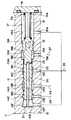
11は油圧モータ3にサーボアクチュエータ10と共に付設された容量制御弁で、該容量制御弁11は、図2等に示すように弁ハウジング12と、該弁ハウジング12内に摺動可能に設けられた後述のスプール19およびピストン21等とによって構成されている。また、容量制御弁11は、図1に示す如く6ポート2位置の油圧パイロット式切換弁等からなり、パイロット管路27からのパイロット圧Pにより大容量位置(a)と小容量位置(b)とに切換制御されるものである。
【0054】
そして、容量制御弁11は、小容量位置(b)にあるときに、高圧管路28からの圧油をサーボアクチュエータ10の油圧室10Cに後述の給排管路29を介して供給する。これにより、傾転ピストン10Aは容量可変部3Aを傾転角が小さくなる矢示B方向に駆動する。また、容量制御弁11は、大容量位置(a)に切換わったときに給排管路29をタンク管路26に接続し、油圧室10C内の圧油をタンク2に向けて排出させる。これにより、サーボアクチュエータ10はスプリング10Bによって容量可変部3Aを傾転角が大きくなる矢示A方向に駆動する。
【0055】
ここで、容量制御弁11の弁ハウジング12には、一端側が開口端13Aとなり、他端側が閉塞端13Bとなった段付のスプール摺動穴13が形成されている。そして、該スプール摺動穴13の外周側には環状の油溝14A,14B,14C,14D,14E,14Fが軸方向に離間して形成されている。
【0056】
また、弁ハウジング12には軸方向に互いに離間してタンクポート15A,15C,15F、パイロットポート15B、高圧ポート15Dおよび圧油給排ポート15Eが形成されている。そして、これらのポート15A〜15Fは油溝14A〜14Fを介してスプール摺動穴13内に連通するものである。
【0057】
16はスプール摺動穴13の開口端13A側を閉塞した蓋体で、該蓋体16は弁ハウジング12の一部を構成し、後述するスプール19の一端側端面との間には油溝14A内に位置してばね室17を形成している。また、蓋体16の内側面には、ばね室17内に向けて突出するロッド状のストッパ18が設けられ、該ストッパ18はスプール19のストロークエンドを図3に示す如く規制するものである。
【0058】
19は弁ハウジング12のスプール摺動穴13内に挿嵌されたスプールで、該スプール19は図2、図4に示す如く外周側にランド19A,19B,19C,19Dが軸方向に互いに離間して形成され、ランド19Bとランド19Cとの間には、油溝14B,14C間を連通,遮断する環状溝19Eが形成されている。また、スプール19のランド19Cとランド19Dとの間には、油溝14D,14E間を連通,遮断する他の環状溝19Fが形成され、該環状溝19Fとランド19Dとにより、圧油給排ポート15Eは高圧ポート15Dとタンクポート15Fとに選択的に連通,遮断されるものである。
【0059】
ここで、スプール19は一端側に位置するランド19A側が最大径となった段付スプールとして形成され、ランド19Bに対向するランド19Aの段差部(端面側)は、パイロット管路27からのパイロット圧Pを受圧する第1の受圧部19Gとなっている。そして、ランド19Aは外径Da 、ランド19Bは外径Db に形成され、受圧部19Gは数1の式による受圧面積S1 を有している。
【0060】
【数1】
これにより、受圧部19Gは受圧面積S1 をもってパイロット管路27からのパイロット圧Pを常時受圧する。そして、このパイロット圧Pが昇圧することにより、スプール19は後述の戻しばね24に抗して矢示C方向に摺動変位するものである。
【0062】
20はスプール19に形成され軸方向に延びた有底穴からなる軸穴で、該軸穴20は一端側が底部となって閉塞され、他端側がスプール19の端面に開口している。そして、軸穴20は図4に示すように比較的小さい穴径Dc (Dc <Db <Da )をもって形成され、軸穴20の底部は後述する油室22内の圧力を、
【0063】
【数2】
S2 =Dc2×π/4
なる受圧面積S2 をもって受承する第2の受圧部20Aとなっている。
【0064】
21は軸穴20内に摺動可能に挿嵌されたピストンで、該ピストン21は軸穴20の開口端側を常に閉塞し、その一端側は軸穴20の底部との間に油室22を画成している。また、ピストン21の他端側は、図3に示す如くスプール19の端面から軸方向に突出し、油室22内のパイロット圧Pによる油圧反力を受承するためスプール摺動穴13の閉塞端13B側に当接している。
【0065】
23は油室22の位置でスプール19の径方向に穿設された油路としての小孔で、該小孔23は環状溝19Eの位置でスプール19の外周面に開口している。そして、小孔23は、スプール19の摺動位置に応じて油室22をタンクポート15C(油溝14C)とパイロットポート15B(油溝14B)とに選択的に連通,遮断するものである。
【0066】
この場合、スプール19は、小孔23による油室22とタンクポート15C,パイロットポート15Bとの連通,遮断を零ラップで行う。このため、ランド19B,19C間の環状溝19Eの軸方向長さは、油溝14B,14C間の離間寸法にほぼ一致する寸法をもって形成されている。そして、小孔23は油室22をパイロットポート15Bに連通させるときに、環状溝19Eにより油室22をタンクポート15Cに対してほぼ同時に遮断し、油室22をタンクポート15Cに連通させるときにはパイロットポート15Bに対してほぼ同時に遮断する構成となっている。
【0067】
24は蓋体16とスプール19との間に位置してばね室17内に配設された付勢手段を構成する戻しばねで、該戻しばね24は一端側がストッパ18の外周側に挿通され、他端側はスプール19の一端側に嵌合等の手段により取付けられている。そして、戻しばね24はスプール19を閉塞端13B側に向け矢示D方向の付勢力Fa をもって常時付勢し、これにより容量制御弁11は、図1に示す小容量位置(b)に保持されるものである。
【0068】
25は油圧モータ3からのドレン(漏洩油)をタンク2側に排出するドレン管路、26は容量制御弁11のタンクポート15A,15C,15Fをタンク2に常時接続するタンク管路を示している。
【0069】
また、27は容量制御弁11のパイロットポート15Bに接続されたパイロット管路で、該パイロット管路27はカウンタバランス弁6のセンタバイパスポート8Aに接続され、油圧モータ3のモータ駆動圧(負荷圧)をパイロット圧Pとして容量制御弁11のパイロットポート15Bに導くものである。
【0070】
28はシャトル弁9を容量制御弁11の高圧ポート15Dに接続した高圧管路で、該高圧管路28は、主管路4A,4Bの管路部4A2 ,4B2 からシャトル弁9で選択した高圧側の圧油を容量制御弁11の高圧ポート15Dに導くものである。
【0071】
29はサーボアクチュエータ10の油圧室10Cを容量制御弁11の圧油給排ポート15Eに接続した給排管路である。さらに、30はカウンタバランス弁6のセンタバイパスポート8Aに接続された他のタンク管路で、該タンク管路30はカウンタバランス弁6の圧力制御弁8が中立位置(イ)に復帰したときに、センタバイパスポート8Aをタンク2に接続する。これにより、パイロット管路27内のパイロット圧Pはタンク圧レベルまで低下するものである。
【0072】
本実施の形態による容量制御弁11を備えた油圧ショベルの走行用油圧回路は上述の如き構成を有するもので、次に、その作動について説明する。
【0073】
まず、油圧ショベルのオペレータが車両を走行駆動するために、図1に示す方向制御弁5を中立位置(イ)から切換位置(ロ)に切換えると、油圧ポンプ1からの圧油はモータ駆動圧となって主管路4A側から油圧モータ3に供給される。そして、このときにカウンタバランス弁6の圧力制御弁8は管路部4A1 ,4B1 間の差圧で中立位置(イ)から切換位置(ロ)側に切換わり、油圧モータ3からの戻り油を圧力制御弁8を介して主管路4B(管路部4B1 )側からタンク2へと排出させ、これによって車両は前進方向に走行駆動される。
【0074】
一方、走行用の方向制御弁5を中立位置(イ)から切換位置(ハ)に切換えたときには、主管路4B側にモータ駆動圧が供給され、油圧モータ3は前述の場合とは逆向きに回転駆動される。そして、この場合には圧力制御弁8が中立位置(イ)から切換位置(ハ)に切換わり、油圧モータ3からの戻り油を圧力制御弁8を介して主管路4A(管路部4A1 )側からタンク2へと排出させ、これによって車両は後進方向に走行駆動される。
【0075】
ここで、車両の走行時に圧力制御弁8が中立位置(イ)から切換位置(ロ)または(ハ)に切換わった状態では、圧力制御弁8のセンタバイパスポート8Aが油圧源側の管路部4A1 または4B1 に接続され、モータ駆動圧はパイロット圧Pとなってパイロット管路27から容量制御弁11のパイロットポート15Bに供給される。
【0076】
また、アクチュエータ側の管路部4A2 ,4B2 側ではシャトル弁9によってモータ駆動圧が選択され、選択された圧油は高圧管路28から容量制御弁11の高圧ポート15Dに導かれる。
【0077】
そして、容量制御弁11のパイロットポート15Bに供給されたパイロット圧Pは、図2に示すスプール19の受圧部19Gに作用し前記数1の式による受圧面積S1 をもって、スプール19を押圧力F1 で戻しばね24の付勢力Fa に抗して矢示C方向に押圧する。
【0078】
【数3】
F1 =S1 ×P
【0079】
また、戻しばね24の付勢力Fa は、
【0080】
【数4】
Fa =S1 ×P1 =(S1 +S2 )×P2
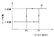
なる関係を満たすように予め設定され、図5に示す特性線31の如くパイロット圧Pが圧力P1 ,P2 (P1 >P2 )の間で変化するときに、モータ容量の切換制御圧にヒステリシス特性が与えられるものである。
【0081】
即ち、車両が坂道を登る登坂走行時等には、油圧モータ3の負荷圧が上昇し、パイロット圧Pは圧力P1 以上まで上昇する。そして、このときにスプール19は、受圧部19Gにより矢示C方向の押圧力F1 (F1 =S1 ×P1 )をもって戻しばね24を図3に示す如く撓み変形させ、ストッパ18に当接するストロークエンドまで摺動変位する。
【0082】
これにより、容量制御弁11は戻しばね24の付勢力Fa に抗して図1に示す小容量位置(b)から大容量位置(a)へと切換わり、容量制御弁11の高圧ポート15Dはスプール19のランド19Dにより圧油給排ポート15Eに対して遮断される。このときに、該圧油給排ポート15Eはタンクポート15F(タンク管路26)に連通される。
【0083】
このため、サーボアクチュエータ10は油圧室10Cが給排管路29、容量制御弁11の圧油給排ポート15E、タンク管路26等を介してタンク2と接続され、スプリング10Bによって油圧モータ3の容量可変部3Aを矢示A方向へと大傾転側に駆動する。これにより、モータ容量は、登坂走行に備えて油圧モータ3を高トルクで低速回転できるように大容量に制御される。
【0084】
また、このときに容量制御弁11はスプール19内の油室22が、図3に示すように小孔23、環状溝19E、油溝14Bを介してパイロットポート15Bに接続されることにより、油室22内には例えば圧力P1 以上のパイロット圧Pが供給される。
【0085】
そして、スプール19は受圧部19Gで受圧面積S1 をもってパイロット圧Pを受圧する。また、油室22内の受圧部20A側では、前記数2の式による受圧面積S2 をもってパイロット圧Pを受圧する。このため、スプール19は受圧部19Gと受圧部20Aとの合計の受圧面積(S1 +S2 )をもってパイロット圧Pを受圧し続けることになる。
【0086】
この結果、油圧モータ3の容量が小容量から大容量に変化して、モータ駆動圧(負荷圧)が僅かに低下した場合でも、パイロット圧Pが圧力P2 以上である間はスプール19が、
【0087】
【数5】
F2 =(S1 +S2 )×P
【0088】
【数6】
F2 ≧Fa
但し、P≧P2
なる押圧力F2 をもって、図3中に示す如く戻しばね24を矢示C方向に撓み変形させ、容量制御弁11を大容量位置(a)に保つものである。
【0089】
一方、車両の登坂走行が終わり、例えば平地の直進走行等に移った場合には、パイロット圧Pが、図5に示す圧力P2 以下まで低下する。これによって、スプール19の押圧力F2 は、戻しばね24の付勢力Fa よりも小さくなるので、スプール19は戻しばね24により矢示D方向に押戻され、図2に示す初期位置まで摺動変位し、容量制御弁11は再び小容量位置(b)に復帰する。
【0090】
そして、このときには容量制御弁11の高圧ポート15Dが圧油給排ポート15Eに連通される。このため、サーボアクチュエータ10は油圧室10C内に、シャトル弁9で選択した高圧管路28からの圧油が給排管路29等を介して供給され、傾転ピストン10Aにより油圧モータ3の容量可変部3Aを矢示B方向へと小傾転側に駆動する。これにより、油圧モータ3の容量を平地走行に適した小容量に制御でき、車両を低トルクで高速走行させることができる。
【0091】
また、このときに容量制御弁11はスプール19内の油室22が、図2に示すように小孔23、油溝14Cを介してタンクポート15Cに接続され、油室22内の圧力はタンク圧レベルまで低下する。このため、スプール19は、油室22内の受圧部20A側でパイロット圧Pを受圧することなく、受圧部19G側でのみ受圧面積S1 をもってパイロット圧Pを受圧することになり、スプール19は受圧面積S1 に減少される。
【0092】
この結果、油圧モータ3の容量が大容量から小容量に変化して、モータ駆動圧(負荷圧)が僅かに増加した場合でも、パイロット圧Pが圧力P1 に達するまでの間はスプール19が、数7の式による押圧力F1 で戻しばね24を図2中の矢示C方向に押圧するに留まり、
【0093】
【数7】
F1 <Fa
但し、P<P1
スプール19は戻しばね24により初期位置に付勢され、容量制御弁11を小容量位置(b)に保持するものである。
【0094】
かくして、本実施の形態によれば、スプール19の一端側に最大径のランド19Aを設けて環状の受圧部19Gを形成し、該受圧部19Gによりパイロットポート15Bからのパイロット圧Pを受圧面積S1 をもって受圧させる。そして、スプール19の他端側から軸方向に延びる有底の軸穴20内には、ピストン21を摺動可能に挿嵌して油室22を画成し、該油室22を小孔23によりスプール19の摺動位置に応じてタンクポート15Cとパイロットポート15Bとに選択的に連通,遮断する構成としている。
【0095】
そして、スプール19が図2に示す初期位置、即ち容量制御弁11が小容量位置(b)にある間は、油室22をタンクポート15Cに連通させることにより、スプール19のパイロット圧Pに対する受圧面積を受圧部19G側の受圧面積S1 のみに減少させる。この結果、モータ駆動圧(パイロット圧P)が圧力P1 以上に上昇するまでは、スプール19を戻しばね24によって初期位置に保持でき、容量制御弁11を小容量位置(b)に保つことができる。
【0096】
また、モータ駆動圧が圧力P1 以上に上昇したときには、スプール19が戻しばね24に抗してストロークエンドまで摺動変位する。これにより、油室22内に小孔23を通じてパイロットポート15Bからのパイロット圧Pを導入し、油室22内の受圧部20Aによる受圧面積S2 分だけスプール19の受圧面積を増大でき、合計の受圧面積(S1 +S2 )をもってパイロット圧Pを受圧し続けることができる。
【0097】
このため、油圧モータ3の容量が小容量から大容量に増加し、モータ駆動圧が僅かに減少したような場合でも、大きな受圧面積(S1 +S2 )をもってスプール19を図3に示すスロークエンドに保持できる。そして、モータ駆動圧が平地走行時の圧力P2 以下に低下するまで、容量制御弁11を大容量位置(a)に切換えておくことにより、油圧モータ3のモータ容量を大容量に保つことができる。
【0098】
従って、本実施の形態によれば、容量制御弁11の切換制御圧に圧力P1 ,P2 の範囲で、図5に示すヒステリシス特性を与えることができ、容量の切換えに伴うハンチング現象を防止できる。これにより、容量制御を安定させて自動的に行うことができる。また、容量制御弁11を弁ハウジング12、スプール19、ピストン21および戻しばね24によって構成できるため、部品点数を少なくして組立時の作業性を向上できると共に、全体をコンパクトに形成して小型化を図ることができる。
【0099】
また、スプール19を一端側が大径となった段付スプールとして形成し、スプール19の外周側には最大径となったランド19Aの位置に、パイロット圧Pの受圧部19Gを設ける構成としているから、スプール19の軸方向長さを短くでき、容量制御弁11全体を小型化することができる。
【0100】
さらに、スプール19内に画成した油室22は、容量制御弁11の切換制御時にパイロットポート15Bとタンクポート15Cとにほぼ零ラップで連通,遮断される構成としているため、パイロット圧Pに対するスプール19の受圧面積を容量の切換時に瞬間的に増減させることができ、スプール19を初期位置とストロークエンドとの間で円滑に摺動変位できる。そして、モータ容量の切換えに伴うハンチング現象の発生を良好に抑えることができ、安定した容量制御を実現することができる。
【0101】
次に、図6ないし図8は本発明の第2の実施の形態を示し、本実施の形態の特徴は、容量制御弁に外部指令圧ポートを追加して設け、外部指令圧を外部選択手段で選択することにより、モータ容量を大容量に固定する制御と、容量自動切換制御とを運転条件に合わせて選択的に行う構成としたことにある。なお、本実施の形態では前記第1の実施の形態と同一の構成要素に同一の符号を付し、その説明を省略するものとする。
【0102】
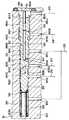
図中、41は本実施の形態で採用した容量制御弁で、該容量制御弁41は、図7に示すように弁ハウジング42と、後述のスプール49およびピストン51等とによって構成されている。そして、容量制御弁41は前記実施の形態で述べた容量制御弁11とほぼ同様に構成されている。しかし、該容量制御弁41は後述する指令圧管路59からの外部指令圧とパイロット管路27からのパイロット圧Pにより大容量位置(a)と小容量位置(b)とに切換制御されるものである。
【0103】
ここで、容量制御弁41の弁ハウジング42には、一端側が開口端43Aとなり、他端側が閉塞端43Bとなった段付のスプール摺動穴43が形成され、該スプール摺動穴43の外周側には環状の油溝44A,44B,44C,44D,44Eが軸方向に離間して形成されている。
【0104】
また、弁ハウジング42には軸方向に互いに離間して外部指令圧ポート45A、パイロットポート45B、タンクポート45C,45F、高圧ポート45Dおよび圧油給排ポート45Eが形成され、これらのポート45A〜45Eは油溝44A〜44Eを介してスプール摺動穴43内に連通するものである。
【0105】
46はスプール摺動穴43の開口端43A側を閉塞した蓋体で、該蓋体46は弁ハウジング42の一部を構成し、後述するスプール49の一端側端面との間には油溝44A内に位置して外部指令圧室47を形成している。
【0106】
48はスプール摺動穴43の閉塞端43Aとスプール49の他端側端面との間に形成されたばね室で、該ばね室48内には後述の戻しばね56、ストッパ55等が配設されている。また、ばね室48はタンクポート45F、タンク管路26を介してタンク2に常時接続されている。
【0107】
49は弁ハウジング42のスプール摺動穴43内に挿嵌されたスプールで、該スプール49は図7、図8に示す如く外周側にランド49A,49B,49C,49D,49Eが軸方向に互いに離間して形成されている。また、スプール49のランド49Dとランド49Eとの間には、油溝44D,44E間を連通,遮断する環状溝49Fが形成されている。そして、スプール49は環状溝49Fとランド49Eとにより、圧油給排ポート45Eを高圧ポート45Dとタンクポート45Fとに選択的に連通,遮断するものである。
【0108】
ここで、スプール49は一端側に位置するランド49A側が最大径となった段付スプールとして形成され、ランド49Bに対向するランド49Aの段差部(端面側)は、パイロット管路27からのパイロット圧を受圧する環状の第1の受圧部49Gとなっている。そして、該受圧部49Gは前述した第1の実施の形態によるスプール19の受圧部19Gと同様に、前記数1の式による受圧面積S1 を有している。
【0109】
また、スプール49の外周側には、ランド49B,49C間に環状の細幅溝49Hが形成され、ランド49C,49D間には環状の細幅溝49Jが形成されている。そして、これらの細幅溝49H,49Jは、後述する油孔53,54の開口端側に位置し、後述の油室52をパイロットポート45Bとタンクポート45Cとに対してほぼ零ラップで連通,遮断させる。
【0110】
このため、細幅溝49Hが油溝44Bに連通(遮断)するときには、細幅溝49Jをほぼ同時に油溝44Cに対して遮断(連通)させるものである。さらに、スプール49のランド49A側に位置する一端側端面は、前記受圧部49Gとは逆向きに外部指令圧を受圧する指令圧受圧部49Kとなっている。そして、該指令圧受圧部49Kは、外部指令圧室47内で後述の数8式による受圧面積S3 を有する構成となっている。
【0111】
50はスプール49に形成され軸方向に延びた有底穴からなる軸穴で、該軸穴50は一端側が底部となって閉塞され、他端側がスプール49の端面に開口している。そして、軸穴50は第1の実施の形態で述べた軸穴20とほぼ同様に、その底部側に後述する油室52内の圧力を受圧面積S2 をもって受圧する第2の受圧部50Aを有するものである。
【0112】
51は軸穴50内に摺動可能に挿嵌されたピストンで、該ピストン51は軸穴50の開口端側を常に閉塞し、その一端側は軸穴50の受圧部50Aとの間で油室52を画成している。また、ピストン51の他端側は、図7に示す如くスプール49の端面から軸方向に突出し、油室52内のパイロット圧Pによる油圧反力を受承すべくストッパ55の端面に当接するものである。
【0113】
53,54は油室52の位置でスプール49の径方向に穿設された油孔で、該油孔53,54は、細幅溝49H,49Jの位置でスプール49の外周面に開口している。そして、油孔53,54と細幅溝49H,49Jとは、スプール49の摺動位置に応じて油室52をパイロットポート45B(油溝44B)とタンクポート45C(油溝44C)とに対して選択的に連通,遮断する油路を構成するものである。
【0114】
この場合、油孔53は細幅溝49H、油溝44Bを介してパイロットポート45Bに連通,遮断され、油孔54は細幅溝49J、油溝44Cを介してタンクポート45Cに連通,遮断される。そして、これらの油孔53,54は、スプール49の摺動変位時に油室52とパイロットポート45B,タンクポート45Cとの連通,遮断を零ラップで行うものである。このため、油孔53,54に常時連通する細幅溝49H,49Jは、油溝44B,44Cの離間寸法に従って予め決められる所定の間隔(軸方向の間隔)をもって形成されている。
【0115】
これにより、細幅溝49Hが油溝44Bに連通するときには、これとほぼ同時に細幅溝49Jが油溝44Cに対して遮断される。また、細幅溝49Jが油溝44Cに連通するときには、これとほぼ同時に細幅溝49Hが油溝44Bに対して遮断されるものである。
【0116】
また、油孔54は油孔53に比較して小径に形成された絞り通路を構成している。そして、油孔54は、図8に示す如く油室52をタンクポート45Cに連通させたときに、油室52内の圧油がタンクポート45C側に向けて噴出するのを抑え、タンクポート45C側でサージ圧等が発生するのを抑制する機能を有している。
【0117】
55はスプール摺動穴43の閉塞端43B側に位置して弁ハウジング42内に設けられたストッパで、該ストッパ55は円柱状のロッド等からなり、スプール摺動穴43の閉塞端43B側からばね室48内に向けて突出している。そして、ストッパ55の一端側はピストン51の他端に当接する。また、ストッパ55は、スプール49が図8に示す如く摺動変位したときに、スプール49の端面に当接し、該スプール49のストロークエンドを規制するものである。
【0118】
56は弁ハウジング42とスプール49との間に位置してばね室48内に配設された付勢手段を構成する戻しばねで、該戻しばね56は一端側がスプール49の端部に嵌合等の手段を用いて取付けられ、他端側はストッパ55の外周側に挿通されてスプール摺動穴43の閉塞端43Bに当接している。そして、戻しばね56はスプール49を矢示C方向に付勢力Fb をもって常時付勢し、これにより容量制御弁41は、図6に示す大容量位置(a)に保持されるものである。
【0119】
57は外部指令圧用の油圧源となるパイロットポンプ、58は該パイロットポンプ57の最大吐出圧を決めるリリーフ弁で、該リリーフ弁58はパイロットポンプ57の吐出側に過剰圧が発生すると開弁し、この過剰圧をタンク2側にリリーフさせるものである。
【0120】
59は容量制御弁41の外部指令圧ポート45Aに接続された指令圧管路、60は該指令圧管路59をタンク2とパイロットポンプ57とに選択的に接続する外部選択手段としての圧力選択弁で、該圧力選択弁60は油圧ショベルのオペレータ等が操作レバー60Aを手動操作することにより、容量固定位置(c)と自動切換位置(d)とのいずれかに切換えられる。
【0121】
そして、圧力選択弁60を容量固定位置(c)に切換えている間は、指令圧管路59がタンク2に接続されることにより、容量制御弁41の外部指令圧室47は圧力がタンク圧レベルとなっている。このため、スプール49は図7に示す初期位置に戻しばね56等により付勢され、容量制御弁41は図6に示す大容量位置(a)に保持されるものである。
【0122】
また、圧力選択弁60を自動切換位置(d)に切換えている間は、指令圧管路59がパイロットポンプ57側に接続され、後述の減圧弁61により設定された圧力値Pg の外部指令圧が容量制御弁41の外部指令圧室47に供給される。そして、容量制御弁41のスプール49は、外部指令圧47内の受圧部49Kが圧力値Pg の外部指令圧を受圧することにより、戻しばね56に抗して矢示D方向に押圧されるものである。
【0123】
61はパイロットポンプ57と圧力選択弁60との間に設けられた減圧弁で、該減圧弁61は指令圧管路59内に供給する外部指令圧が、後述の数9〜数12の式を満たす圧力値Pg 以上に昇圧するのを抑えるため、常時は開弁する。そして、減圧弁61は、パイロットポンプ57からの吐出圧が圧力値Pg 以上に上昇すると、閉弁して吐出圧の供給を停止するものである。
【0124】
かくして、このように構成される本実施の形態でも、前記第1の実施の形態とほぼ同様の作用効果を得ることができるが、特に本実施の形態では、容量制御弁41に外部指令圧ポート45A、外部指令圧室47等を設け、圧力選択弁60により外部指令圧を選択して供給する構成としたから、下記のような作用効果を得ることができる。
【0125】
即ち、圧力選択弁60を容量固定位置(c)に切換えている間は、指令圧管路59がタンク2に接続され、容量制御弁41の外部指令圧室47は圧力がタンク圧レベルとなる。このため、スプール49には指令圧受圧部49Kによる矢示D方向の押圧力が発生することはなく、スプール49が図7に示す初期位置に戻しばね56等で付勢され続けることにより、容量制御弁41は図6に示す大容量位置(a)に保持され、油圧モータ3は大容量に固定される。
【0126】
一方、圧力選択弁60を容量固定位置(c)から自動切換位置(d)に切換えると、容量制御弁41の外部指令圧室47には指令圧管路59、外部指令圧ポート45Aを通じて圧力値Pg の外部指令圧が供給される。
【0127】
この場合、スプール49のランド49Aは、第1の実施の形態で述べたスプール19のランド19Aと同様に、図4に例示した外径Da を有しているので、スプール49の受圧部49Kは外部指令圧室47内で下記の数8式による受圧面積S3 をもって外部指令圧を受圧するものである。
【0128】
【数8】
S3 =(Da2×π/4)
【0129】
そして、外部指令圧を圧力値Pg に設定したときには、
【0130】
【数9】
F3 =S3 ×Pg
なる押圧力F3 をもってスプール49は矢示D方向に押圧される。
【0131】
また、スプール49は図7に示す初期位置において、パイロットポート45Bから導かれるパイロット圧Pを受圧部49Gで受圧面積S1 をもって受圧する。そして、油室52内の受圧部50A側では受圧面積S2 をもってパイロット圧Pを受圧する。このため、スプール49には前記数5による押圧力F2 が図7中の矢示C方向に働くことになる。
【0132】
そして、戻しばね56は付勢力Fb でスプール49を矢示C方向に付勢しているため、スプール49には矢示C方向に押圧力F2 と付勢力Fb とが作用し、矢示D方向には外部指令圧による押圧力F3 が作用し、
【0133】
【数10】
F3 >F2 +Fb
なる関係を満たすときに、スプール49は圧力値Pg の外部指令圧により図8に示すストロークエンドまで摺動変位する。
【0134】
これにより、スプール49は、パイロット圧Pが図5に例示した特性線31の如く圧力P2 以下まで低下した状態で、外部指令圧室47に圧力値Pg の外部指令圧が供給されたときに、図8に示すストロークエンド位置に摺動変位する。このため、容量制御弁41は、図6に示す大容量位置(a)から小容量位置(b)へと切換制御されるものである。
【0135】
そして、図8に示すストロークエンドの状態では、スプール49内の油室52が油孔54、油溝44Cを介してタンクポート45Cに接続され、油室52内の圧力はタンク圧レベルまで低下するため、スプール49は油室52内の受圧部50A側でパイロット圧Pを受圧することなく、受圧部49G側でのみ受圧面積S1 をもってパイロット圧Pを受圧することになり、スプール49は受圧面積S1 に減少される。
【0136】
この結果、スプール49は前記数3による押圧力F1 と付勢力Fb とが図8中の矢示C方向に作用し、矢示D方向には外部指令圧による押圧力F3 を受けることによって、
【0137】
【数11】
F3 >F1 +Fb
なる関係を満たす間は、ストロークエンドである小容量位置(b)に容量制御弁41が保持される。
【0138】
そして、油圧モータ3の容量が大容量から小容量に変化し、モータ駆動圧(負荷圧)が僅かに増加した場合でも、パイロット圧Pが圧力P1 に達するまでの間はスプール49が、数11の式による関係下で図8に示すストロークエンドに留まるものである。
【0139】
次に、この状態でパイロット圧Pが図5に例示した圧力P1 以上まで上昇すると、スプール49の受圧部49Gに発生する矢示C方向の押圧力F1 が大きくなるために、
【0140】
【数12】
F3 <F1 +Fb
但し、P≧P1
となり、スプール49は外部指令圧室47内の圧力に抗して矢示C方向に摺動変位し、図7に示す初期位置に復帰する。これにより、容量制御弁41は、図6に示す大容量位置(a)に戻るものである。
【0141】
そして、この状態ではスプール49の受圧面積が面積(S1 +S2 )に増加するため、モータ容量が小容量から大容量に変化するに伴ってモータ駆動圧が僅かに減少するような場合でも、容量制御弁41を大容量位置(a)に保持でき、モータ駆動圧(パイロット圧P)が再び圧力P2 以下に減少するまで、モータ容量を大容量に保つことができる。これにより、本実施の形態でも、図5に示すヒステリシス特性を得ることができる。
【0142】
従って、本実施の形態では、外部指令圧用の圧力選択弁60を容量固定位置(c)に切換えている間は、モータ容量を大容量に固定でき、例えば車両のステアリング操作等を容易に行うことができ、オペレータの負担を軽減できる。また、圧力選択弁60を自動切換位置(d)に切換えたときには、モータ駆動圧が増,減するに応じて容量制御弁41を自動的に切換制御でき、モータ容量の自己圧制御を適切に行うことができる。
【0143】
さらに、油室52の圧力切換タイミングに加工誤差等による僅かなズレが発生し、パイロットポート45Bとタンクポート45Cとが油室52に一緒に連通するような区間が存在する場合でも、油室52はタンクポート45Cに小径の油孔54を介して連通するので、該油孔54により圧油を絞ることができ、例えば油室52内の高圧(パイロット圧P)がタンクポート45C側に噴出するのを抑え、タンクポート45C側でサージ圧が発生する等の事態を防ぐことができる。
【0144】
次に、図9は本発明の第3の実施の形態を示し、本実施の形態では前記第2の実施の形態と同一の構成要素に同一の符号を付し、その説明を省略するものとする。しかし、本実施の形態の特徴は、容量制御弁71のスプール72を、第2の実施の形態で用いたスプール49とは異なる形状に形成したことにある。
【0145】
ここで、スプール72は、前記第1の実施の形態で述べたスプール19とほぼ同様に、外周側にランド72A,72B,72C,72Dが軸方向に互いに離間して形成され、ランド72Bとランド72Cとの間には、油溝44B,44C間を連通,遮断する環状溝72Eが形成されている。また、スプール72のランド72Cとランド72Dとの間には、油溝44D,44E間を連通,遮断する他の環状溝72Fが形成され、該環状溝72Fとランド72Dとにより、圧油給排ポート45Eを高圧ポート45Dとタンクポート45Fとに選択的に連通,遮断させる構成となっている。
【0146】
また、スプール72は一端側に位置するランド72A側が最大径となった段付スプールとして形成され、ランド72Bに対向するランド72Aの段差部(端面側)は、パイロット管路27からのパイロット圧を受圧する環状の第1の受圧部72Gとなっている。そして、該第1の受圧部72Gは前記数1の式による受圧面積S1 を有している。
【0147】
さらに、スプール72のランド72A側に位置する一端側端面は、前記受圧部72Gとは逆向きに外部指令圧を受圧する指令圧受圧部72Hとなり、該指令圧受圧部72Hは、外部指令圧室47内で前記数8の式による受圧面積S3 を有するものである。
【0148】
また、スプール72には軸方向に延びた有底穴からなる軸穴73が形成され、該軸穴73内にはピストン51が挿嵌されることにより、油室74が画成されている。そして、軸穴73の底部側には油室74内の圧力を、前記数2の式による受圧面積S2 をもって受圧する第2の受圧部73Aが形成されている。
【0149】
一方、スプール72の径方向には油路としての小孔75が穿設され、該小孔75は第1の実施の形態で述べた小孔23とほぼ同様に、スプール72の摺動位置に応じて油室74をタンクポート45C(油溝44C)とパイロットポート45B(油溝44B)とに選択的に連通,遮断する構成となっている。
【0150】
かくして、このように構成される本実施の形態でも、前記第2の実施の形態とほぼ同様の作用効果を得ることができる。
【0151】
次に、図10ないし図12は本発明の第4の実施の形態を示し、本実施の形態の特徴は、スプールの外周側に第1の受圧部を形成すると共に、スプールの軸穴内には油室を形成し、該油室内にパイロット圧を導いたときには、油室内の第2の受圧部に第1の受圧部とは逆向きにパイロット圧を作用させることにより、パイロット圧に対するスプールの受圧面積を変化させる構成としたことにある。なお、本実施の形態では前記第2の実施の形態と同一の構成要素に同一の符号を付し、その説明を省略するものとする。
【0152】
図中、81は本実施の形態で採用した容量制御弁で、該容量制御弁81は、図11に示すように弁ハウジング82と、後述のスプール89およびピストン91等とによって構成されている。そして、容量制御弁81は第2の実施の形態で述べた容量制御弁41とほぼ同様に構成され、指令圧管路59からの外部指令圧と後述するパイロット管路98からのパイロット圧Pにより大容量位置(a)と小容量位置(b)とに切換制御されるものである。
【0153】
ここで、容量制御弁81の弁ハウジング82には、一端側が開口端83Aとなり、他端側が閉塞端83Bとなった段付のスプール摺動穴83が形成され、該スプール摺動穴83の外周側には環状の油溝84A,84B,84C,84D,84Eが軸方向に離間して形成されている。
【0154】
また、弁ハウジング82には、軸方向に互いに離間して外部指令圧ポート85A、パイロットポート85B、タンクポート85C,85F、高圧ポート85Dおよび圧油給排ポート85Eが形成され、これらのポート85A〜85Eは油溝84A〜84Eを介してスプール摺動穴83内に連通するものである。
【0155】
86はスプール摺動穴83の開口端83A側を閉塞した蓋体で、該蓋体86は弁ハウジング82の一部を構成し、後述するスプール89の一端側端面との間には油溝84A内に位置して外部指令圧室87を形成している。
【0156】
88はスプール摺動穴83の閉塞端83Bとスプール89の他端側端面との間に形成されたばね室で、該ばね室88内には後述の戻しばね96、ストッパ95等が配設されている。また、ばね室88はタンクポート85F、タンク管路26を介してタンク2に常時接続されている。
【0157】
89は弁ハウジング82のスプール摺動穴83内に挿嵌されたスプールで、該スプール89は図11、図12に示す如く外周側にランド89A,89B,89C,89Dが軸方向に互いに離間して形成されている。また、スプール89のランド89Cとランド89Dとの間には、油溝84D,84E間を連通,遮断する環状溝89Eが形成されている。そして、スプール89は、環状溝89Eとランド89Dとにより、圧油給排ポート85Eを高圧ポート85Dとタンクポート85Fとに選択的に連通,遮断するものである。
【0158】
ここで、スプール89は一端側に位置するランド89A側が最大径となった段付スプールとして形成され、ランド89Aの外周側には後述の油孔93と対応する位置に環状の細幅溝89Fが形成されている。また、ランド89Bに対向するランド89Aの段差部(端面側)は、パイロット管路98からのパイロット圧を受圧する環状の第1の受圧部89Gとなっている。そして、該第1の受圧部89Gは前述した第1の実施の形態によるスプール19の受圧部19Gと同様に、前記数1の式による受圧面積S1 を有している。
【0159】
また、スプール89の外周側には、ランド89B,89C間に環状の細幅溝89Hが形成されている。そして、細幅溝89F,89Hは、後述する油孔93,94の開口端側に位置し、後述の油室92をパイロットポート85Bとタンクポート85Cとに対してほぼ零ラップで連通,遮断させるものである。このため、細幅溝89Fが油溝84Bに連通(遮断)するときには、細幅溝89Hをほぼ同時に油溝84Cに対して遮断(連通)させる構成となっている。
【0160】
さらに、スプール89のランド89A側に位置する一端側端面は、前記受圧部89Gとは逆向きに外部指令圧を受圧する指令圧受圧部89Jとなり、該指令圧受圧部89Jは、前記数8の式による受圧面積S3 をもって外部指令圧室87内の外部指令圧を受圧するものである。
【0161】
90はスプール89に形成され軸方向に延びた有底穴からなる軸穴で、該軸穴90は一端側がスプール89の端面に開口し、他端側は底部となって閉塞されている。そして、軸穴90の底部側は第2の受圧部90Aとなり、該第2の受圧部90Aは後述の油室92内に位置して、前記受圧面積S1 よりも小さい受圧面積S4 (S4 <S1 <S3 )を有するものである。
【0162】
91は軸穴90内に摺動可能に挿嵌されたピストンで、該ピストン91は軸穴90の開口端側を常に閉塞し、その一端側は蓋体86の表面に当接している。そして、ピストン91は他端側により軸穴90の底部との間で油室92を画成しているものである。
【0163】
93,94は油室92の位置でスプール89の径方向に穿設された油孔で、該油孔93,94は、細幅溝89F,89Hの位置でスプール89の外周面に開口している。そして、油孔93,94と細幅溝89F,89Hは、スプール89の摺動位置に応じて油室92をパイロットポート85B(油溝84B)とタンクポート85C(油溝84C)とに対して選択的に連通,遮断する油路を構成するものである。
【0164】
この場合、油孔93は細幅溝89F、油溝84Bを介してパイロットポート85Bに連通,遮断され、油孔94は細幅溝89H、油溝84Cを介してタンクポート85Cに連通,遮断される。そして、これらの油孔93,94は、スプール89の摺動変位時に油室92とパイロットポート85B,タンクポート85Cとの連通,遮断を零ラップで行う。このため、油孔93,94に常時連通する細幅溝89F,89Hは、油溝84B,84Cの離間寸法に従って予め決められる所定の間隔(軸方向の間隔)をもって形成されている。
【0165】
また、油孔94は油孔93に比較して小径に形成された絞り通路を構成している。そして、油孔94は、図11に示す如く油室92をタンクポート85Cに連通させたときに、油室92内の圧油がタンクポート85C側に向けて噴出するのを抑え、タンクポート85C側でサージ圧等が発生するのを抑制する機能を有している。
【0166】
95はスプール摺動穴83の閉塞端83B側に位置して弁ハウジング82内に設けられたストッパで、該ストッパ95は円柱状のロッド等からなり、スプール摺動穴83の閉塞端83B側からばね室88内に向けて突出している。そして、ストッパ95の一端側は、スプール89が図12に示す如く摺動変位したときにスプール89の端面に当接し、該スプール89のストロークエンドを規制するものである。
【0167】
96は弁ハウジング82とスプール89との間に位置してばね室88内に配設された付勢手段を構成する戻しばねで、該戻しばね96は一端側がスプール89の端部に嵌合等の手段を用いて取付けられ、他端側はストッパ95の外周側に挿通されてスプール摺動穴83の閉塞端83Bに当接している。そして、戻しばね96はスプール89を矢示C方向に付勢力Fc をもって常時付勢し、これにより容量制御弁81は、図10に示す大容量位置(a)に保持されるものである。
【0168】
97はシャトル弁9と容量制御弁81の高圧ポート85Dとの間を接続する高圧管路、98は該高圧管路97の途中部位から分岐して容量制御弁81のパイロットポートに接続されたパイロット管路を示している。そして、高圧管路97とパイロット管路98とは、油圧モータ3の主管路4A,4Bのうちシャトル弁9により選択した高圧側の圧油(モータ駆動圧)を、容量制御弁81の高圧ポート85Dとパイロットポート85Bとに供給するものである。
【0169】
かくして、このように構成される本実施の形態でも、前記第2の実施の形態とほぼ同様の作用効果を得ることができるが、特に本実施の形態では、スプール89の一端側から他端側に向けて有底の軸穴90を形成し、該軸穴90の底部側には油室92内に位置して受圧面積S4 の受圧部90Aを形成している。そして、油室92内にパイロット圧Pを導入したときには、受圧部90Aによりスプール89に対して矢示D方向の押圧力F4 を、下記の数13式のように発生させる構成としている。
【0170】
即ち、圧力選択弁60を容量固定位置(c)に切換えている間は、前記第2の実施の形態と同様に容量制御弁81は図10に示す大容量位置(a)に保持し、油圧モータ3のモータ容量を大容量に固定できる。
【0171】
そして、圧力選択弁60を容量固定位置(c)から自動切換位置(d)に切換えたときには、容量制御弁81の外部指令圧室87に指令圧管路59、外部指令圧ポート85Aを通じて圧力値Pg の外部指令圧を供給でき、モータ駆動圧であるパイロット圧Pに応じて容量制御を行うことができる。
【0172】
然るに、本実施の形態にあっては、例えば外部指令圧によりスプール89を図12に示すストロークエンドまで摺動変位させ、容量制御弁81を小容量位置(b)に切換えたときに、スプール89内の油室92にパイロットポート85Bからのパイロット圧Pを導くため、この状態でスプール89には、
【0173】
【数13】
F4 =S4 ×P
なる押圧力F4 を、油室92内の受圧部90Aにより矢示D方向に生じさせることができる。
【0174】
一方、スプール89の外周側に形成した受圧部89Gは、パイロットポート85Bからのパイロット圧Pを受圧面積S1 (S1 >S4 )をもって受圧しているから、前記数3による押圧力F1 をスプール89に対し矢示C方向に発生させている。
【0175】
このため、スプール89は図12に示す状態で、
【0176】
【数14】
F5 =F1 −F4 =(S1 −S4 )×P
なる押圧力F5 を矢示C方向に生じさせ、このときのスプール89の受圧面積は面積(S1 −S4 )に減少しているものである。
【0177】
また、スプール89には矢示C方向に戻しばね96の付勢力Fc が作用し、前記数9による外部指令圧の押圧力F3 が矢示D方向に作用しているから、
【0178】
【数15】
F3 >F5 +Fc
なる関係を満たす間、スプール89は圧力値Pg の外部指令圧により図12に示すストロークエンドまで摺動変位し、容量制御弁81は小容量位置(b)に保持される。
【0179】
しかし、この状態でパイロット圧Pが図5に例示した圧力P1 以上まで上昇すると、スプール89の数14の式による矢示C方向の押圧力F5 が大きくなるために、
【0180】
【数16】
F3 <F5 +Fc
但し、P≧P1
なる関係を満たしたときに、スプール89は外部指令圧室87内の圧力に抗して矢示C方向に摺動変位し、図11に示す初期位置に復帰すると共に、容量制御弁81は図10に示す大容量位置(a)に戻るものである。
【0181】
そして、この状態ではスプール89内の油室92が油孔94を介してタンクポート85Cに連通し、油室92内はタンク圧になることにより、前記数13の式による押圧力F4 は零となる。従って、スプール89の受圧面積は、受圧部89Gによる受圧面積S1 となって実質的に増加する。
【0182】
このため、油圧モータ3のモータ容量が小容量から大容量に変化するに伴いモータ駆動圧が僅かに減少するような場合でも、容量制御弁81を大容量位置(a)に保持でき、モータ駆動圧(パイロット圧P)が再び圧力P2 以下に減少するまで、モータ容量を大容量に保つことができる。これにより、本実施の形態でも、図5に示すヒステリシス特性を得ることができる。
【0183】
次に、図13ないし図15は本発明の第5の実施の形態を示し、本実施の形態では前記第4の実施の形態と同一の構成要素に同一の符号を付し、その説明を省略するものとする。
【0184】
しかし、本実施の形態の特徴は、スプール内に軸方向で互いに対向する油室と受圧室とを形成し、前記油室はパイロットポートと外部指令圧ポートとに選択的に連通,遮断させ、他方の受圧室は常にパイロットポートに連通してパイロット圧を受圧する構成とし、前記油室内にパイロット圧を導いたときには、該油室と受圧室とで互い逆向きにパイロット圧を作用させることにより、パイロット圧に対するスプールの受圧面積を変化させる構成としたことにある。
【0185】
図中、101は本実施の形態で採用した容量制御弁で、該容量制御弁101は、図14に示すように弁ハウジング102と、後述のスプール109およびピストン112等とによって構成されている。そして、容量制御弁101は第4の実施の形態で述べた容量制御弁81とほぼ同様に構成され、指令圧管路59からの外部指令圧とパイロット管路98からのパイロット圧Pにより大容量位置(a)と小容量位置(b)とに切換制御されるものである。
【0186】
ここで、容量制御弁101の弁ハウジング102には、一端側が開口端103Aとなり、他端側が閉塞端103Bとなった段付のスプール摺動穴103が形成され、該スプール摺動穴103の外周側には環状の油溝104A,104B,104C,104Dが軸方向に離間して形成されている。
【0187】
また、弁ハウジング102には、軸方向に互いに離間して外部指令圧ポート105A、パイロットポート105B、高圧ポート105C、圧油給排ポート105Dおよびタンクポート105Eが形成され、これらのポート105A〜105Dは油溝104A〜104Dを介してスプール摺動穴103内に連通するものである。
【0188】
106はスプール摺動穴103の開口端103A側を閉塞した蓋体で、該蓋体106は弁ハウジング102の一部を構成し、後述するスプール109の一端側との間には油溝104A内に位置して外部指令圧室107を形成している。
【0189】
108はスプール摺動穴103の閉塞端103Bとスプール109の他端側端面との間に形成されたばね室で、該ばね室108内には後述の戻しばね119、ストッパ118等が配設されている。また、ばね室108はタンクポート105E、タンク管路26を介してタンク2に常時接続されている。
【0190】
109は弁ハウジング102のスプール摺動穴103内に挿嵌されたスプールで、該スプール109は図14、図15に示す如く外周側にランド109A,109B,109C,109Dが軸方向に互いに離間して形成されている。また、スプール109のランド109Cとランド109Dとの間には、油溝104C,104D間を連通,遮断する環状溝109Eが形成されている。そして、スプール109は、環状溝109Eとランド109Dとにより、圧油給排ポート105Dを高圧ポート105Cとタンクポート105Eとに選択的に連通,遮断するものである。
【0191】
また、スプール109の外周側にはランド109A,109B間に細幅の環状溝109Fが形成され、ランド109B,109C間には後述する油孔115の開口端側に位置して他の環状溝109Gが形成されている。そして、環状溝109Fは、後述する油孔114の開口端側に位置し、後述の油室113を外部指令圧ポート105Aとパイロットポート105Bとに対してほぼ零ラップで連通,遮断させる。このため、環状溝109Fの溝幅は、油溝104A,104B間の離間寸法にほぼ一致する寸法となっている。
【0192】
さらに、スプール109のランド109A側に位置する一端側端面は、外部指令圧を受圧する指令圧受圧部109Hとなり、該指令圧受圧部109Hは、前記数8の式による受圧面積S3 をもって外部指令圧室107内の外部指令圧を受圧するものである。
【0193】
110はスプール109に形成され軸方向に延びた有底穴からなる軸穴で、該軸穴110は一端側がスプール109の端面に開口し、他端側は底部となって閉塞されている。そして、軸穴110は第4の実施の形態で述べた軸穴90とほぼ同様に、その底部側が後述する油室113内の圧力を比較的小さい受圧面積S4 をもって受圧する第2の受圧部110Aとなっている。
【0194】
111は軸穴110とは反対側に位置してスプール109に形成された軸方向の有底穴で、該有底穴111は一端側が底部となって閉塞され、他端側はスプール109の端面に開口している。また、有底穴111はスプール109の軸方向で軸穴110と一定間隔をもって対向し、有底穴111は軸穴110よりも大なる穴径に形成されている。そして、有底穴111の底部側はパイロット圧Pを常時受圧する第1の受圧部111Aを構成し、該受圧部111Aは後述の受圧室117内で前記受圧部110Aよりも大なる受圧面積S6 (S6 >S4 )を有しているものである。
【0195】
112は軸穴110内に摺動可能に挿嵌されたピストンで、該ピストン112は軸穴110の開口端側を常に閉塞し、その一端側は蓋体106の表面に当接している。そして、ピストン112は他端側により軸穴110の底部との間で油室113を画成しているものである。
【0196】
114は油室113の位置でスプール109の径方向に穿設された油孔で、該油孔114は、環状溝109Fの位置でスプール109の外周面に開口している。そして、油孔114と環状溝109Fとは、スプール109の摺動位置に応じて油室113を外部指令圧ポート105A(油溝104A)とパイロットポート105B(油溝104B)とに対して選択的に連通,遮断する油路を構成するものである。
【0197】
また、油孔114は後述の油孔115に比較して小径に形成された絞り通路を構成している。そして、油孔114は、図14に示す如く油室113を外部指令圧ポート105Aに連通させたときに、油室113内の圧油が圧力の低い外部指令圧ポート105A側に向けて噴出するのを抑え、外部指令圧ポート105A側にサージ圧等が発生するのを防止する機能を有している。
【0198】
115は受圧室117の位置でスプール109の径方向に穿設された油孔で、該油孔115は、環状溝109Gの位置でスプール109の外周面に開口し、受圧室117をパイロットポート105B(油溝104B)に対して常時連通させる。そして、受圧室117は、パイロットポート105Bから導かれるパイロット圧Pにより、後述の数17式による押圧力F6 をスプール109の矢示C方向に発生する。
【0199】
116は有底穴111内に摺動可能に挿嵌された大径のピストン部材で、該ピストン部材116は有底穴111の開口端側を常に閉塞し、その一端側は有底穴111の底部との間で受圧室117を画成している。また、ピストン部材116は他端側が有底穴111から突出し、その突出端側は受圧室117内の油圧反力を受承すべくストッパ118に常時当接しているものである。
【0200】
118はスプール摺動穴103の閉塞端103B側に位置して弁ハウジング102内に設けられたストッパで、該ストッパ118は円柱状のロッド等からなり、スプール摺動穴103の閉塞端103B側からばね室108内に向けて突出している。そして、ストッパ118の一端側は、ピストン部材116の端面に当接し、スプール109が図15に示す如く摺動変位したときにはスプール109の端面に当接し、該スプール109のストロークエンドを規制するものである。
【0201】
119は弁ハウジング102とスプール109との間に位置してばね室108内に配設された付勢手段を構成する戻しばねで、該戻しばね119は一端側がスプール109の端部に嵌合等の手段を用いて取付けられ、他端側はストッパ118の外周側に挿通されてスプール摺動穴103の閉塞端103B側に当接している。そして、戻しばね119はスプール109を矢示C方向に付勢力Fd をもって常時付勢し、これにより容量制御弁101は、図13に示す大容量位置(a)に保持されるものである。
【0202】
かくして、このように構成される本実施の形態でも、前記第4の実施の形態とほぼ同様の作用効果を得ることができる。しかし、特に本実施の形態では、スプール109の一端側と他端側とに軸方向に延びる有底の軸穴110と有底穴111とを形成し、該軸穴110内には受圧面積S4 の小さい受圧部110Aと油室113をピストン112によって形成し、有底穴111内には大なる受圧面積S6 をもった受圧部111Aと受圧室117を大径のピストン部材116により形成する構成としている。
【0203】
そして、本実施の形態にあっては、スプール109内の受圧室117内にパイロットポート105Bからのパイロット圧Pを常時導くことにより、
【0204】
【数17】
F6 =S6 ×P
なる押圧力F6 を、受圧部111Aによってスプール109の矢示C方向に発生させるものである。
【0205】
これに対して、油室113はスプール109の摺動位置に応じて外部指令圧ポート105Aとパイロットポート105Bとに選択的に連通され、外部指令圧ポート105Aと連通する間は、受圧部110Aが受圧部109Hと共に外部指令圧室107内の外部指令圧を受圧する。
【0206】
一方、スプール109の摺動変位に応じて図15に示すように油室113がパイロットポート105Bに連通したときには、油室113内にパイロット圧Pが導入されることにより、受圧部110Aはスプール109に前記数13の式による矢示D方向の押圧力F4 (F4 =S4 ×P)を発生させる。
【0207】
即ち、外部指令圧によりスプール109を図15に示すストロークエンドまで摺動変位させ、容量制御弁101を小容量位置(b)に切換えたときに、スプール109は矢示C方向に押圧力F6 を受け、矢示D方向には押圧力F4 (F4 <F6 )を受ける。
【0208】
このため、スプール109は図15に示す状態で、
【0209】
【数18】
F7 =F6 −F4 =(S6 −S4 )×P
なる押圧力F7 を矢示C方向に生じさせ、このときのスプール109の受圧面積は面積(S6 −S4 )に減少しているものである。
【0210】
また、スプール109には矢示C方向に戻しばね119の付勢力Fd が作用し、前記数9による外部指令圧の押圧力F3 が矢示D方向に作用しているから、
【0211】
【数19】
F3 >F7 +Fd
なる関係を満たす間、スプール109は圧力値Pg の外部指令圧により図15に示すストロークエンドまで摺動変位し、容量制御弁101は小容量位置(b)に保持される。
【0212】
しかし、この状態でパイロット圧Pが図5に例示した圧力P1 以上まで上昇すると、スプール109の数18の式による矢示C方向の押圧力F7 が大きくなるために、
【0213】
【数20】
F3 <F7 +Fd
但し、P≧P1
なる関係を満たしたときに、スプール109は外部指令圧室107内の圧力に抗して矢示C方向に摺動変位し、図14に示す初期位置に復帰する。これにより、容量制御弁101は図13に示す大容量位置(a)に戻るものである。
【0214】
そして、この状態ではスプール109内の油室113が油孔114を介して外部指令圧ポート105Aに連通し、油室113内にはパイロット圧Pよりも低圧(例えばP/10程度)の外部指令圧が導かれる。そして、この外部指令圧はパイロット圧Pに比較して十分に低い圧力であるので、スプール109は、油室113側で実質的にパイロット圧Pを受圧することはなく、受圧室117側においてパイロット圧Pを受圧し続けるものである。これにより、パイロット圧Pに対するスプール109の受圧面積は、受圧室117による受圧面積S6 となって実質的に増加する。
【0215】
このため、油圧モータ3のモータ容量が小容量から大容量に変化するに伴いモータ駆動圧が僅かに減少するような場合でも、容量制御弁101を大容量位置(a)に保持でき、モータ駆動圧(パイロット圧P)が再び圧力P2 以下に減少するまで、モータ容量を大容量に保つことができる。これにより、本実施の形態でも、図5に示すヒステリシス特性を得ることができる。
【0216】
さらに、本実施の形態にあっては、スプール109内に有底穴111による受圧室117を形成しているから、スプール109の外周側にパイロット圧の受圧部を特別に形成する必要がなく、スプール109の外径寸法を小さくすることができる。
【0217】
次に、図16ないし図18は本発明の第6の実施の形態を示し、本実施の形態の特徴は、容量制御弁の外部指令圧ポートを外部の指令圧供給手段に接続する指令圧管路の途中に、絞りを設ける構成としたことにある。なお、本実施の形態では前記第2の実施の形態と同一の構成要素に同一の符号を付し、その説明を省略するものとする。
【0218】
図中、121は本実施の形態で採用した容量制御弁を示し、該容量制御弁121は、第2の実施の形態で述べた容量制御弁41とほぼ同様に、弁ハウジング122、スプール49、ピストン51、ストッパ55および戻しばね56等により構成されている。そして、容量制御弁121は後述する指令圧管路132からの外部指令圧とパイロット管路27からのパイロット圧Pにより大容量位置(a)と小容量位置(b)とに切換制御されるものである。
【0219】
しかし、本実施の形態による容量制御弁121は、図17に示す如く弁ハウジング122が異なる形状を有し、該弁ハウジング122はスプール摺動穴123の一端側が後述の外部指令圧ポート125Aとなって軸方向に開口している。そして、弁ハウジング122には、外部指令圧ポート125A側に後述のアダプタ126が螺着されている。また、弁ハウジング122には、スプール摺動穴123の他端側に後述のプラグ129が螺着され、スプール摺動穴123の他端側はプラグ129により閉塞されている。
【0220】
また、容量制御弁121の弁ハウジング122には、アダプタ126とプラグ129との間に位置してスプール摺動穴123の外周側に、それぞれ環状の油溝124A,124B,124C,124D,124Eが軸方向に離間して形成されている。さらに、弁ハウジング122には、軸方向に互いに離間して外部指令圧ポート125A、パイロットポート125B、タンクポート125C,125F、高圧ポート125Dおよび圧油給排ポート125Eが形成されている。
【0221】
ここで、これらのポート125A〜125Fのうち、外部指令圧ポート125Aは、スプール摺動穴123の一端側に位置してスプール摺動穴123と実質的に同軸に配設されている。また、パイロットポート125B、タンクポート125C,125F、高圧ポート125Dおよび圧油給排ポート125Eはスプール摺動穴123の径方向に延び、それぞれ油溝124B〜124E等を介してスプール摺動穴123内に連通しているものである。
【0222】
126はスプール摺動穴123の一端側で外部指令圧ポート125Aに螺着して設けられた段付筒状のアダプタで、該アダプタ126は後述の配管部133と共に指令圧管路132を構成している。また、アダプタ126は、この配管部133を外部指令圧ポート125Aに接続するための管継手となっている。そして、アダプタ126は、弁ハウジング122の油溝124A内に位置してスプール49の指令圧受圧部49Kとの間に外部指令圧室127を画成している。
【0223】
128はアダプタ126の内周側に形成された絞りで、該絞り128はアダプタ126内の流路面積を縮小させ、外部指令圧室127内にアダプタ126を介して給排される外部指令圧に絞り作用を与えるものである。
【0224】
そして、容量制御弁121のスプール49が、例えば図18に示す位置から矢示C方向に摺動変位するときには、外部指令圧室127から配管部133側に流出する圧油(外部指令圧)が絞り128で絞り作用を受ける。これにより、外部指令圧室127はダンパ室として機能し、図18に示すスプール49が矢示C方向に速い速度で摺動変位するのを抑制する。
【0225】
129はスプール摺動穴123の他端側に螺着された栓体としてのプラグで、該プラグ129は弁ハウジング122の一部を構成し、アダプタ126とは反対側の位置でスプール摺動穴123を閉塞しているものである。そして、プラグ129はスプール49の他端側端面との間に、前記第2の実施の形態と同様にばね室48を形成し、該ばね室48内には戻しばね56およびストッパ55等が配設されている。
【0226】
130は弁ハウジング122の油溝124B内に位置してスプール摺動穴123とスプール49との間に画成されたパイロット圧受圧室で、該パイロット圧受圧室130はパイロットポート125Bと常時連通し、パイロット管路27からのパイロット圧をスプール49の第1の受圧部49Gで受圧させることにより、スプール49は矢示C方向の押圧力を受けるものである。
【0227】
131は外部指令圧室127とパイロット圧受圧室130との間を遮断するシール部材で、該シール部材131は弁ハウジング122の油溝124A,124B間に位置してスプール摺動穴123の周壁側に装着され、スプール49のランド49A外周側に摺接するものである。
【0228】
そして、シール部材131は、弁ハウジング122とスプール49との間に設けられることにより、パイロットポート125Bと外部指令圧室127との間を液密にシールし、例えばパイロットポート125Bからパイロット圧受圧室130内に供給された圧油(パイロット圧)が外部指令圧室127内に漏洩するのを防止するものである。
【0229】
次に、132は容量制御弁121の外部指令圧ポート125Aに接続された指令圧管路で、該指令圧管路132は、前記アダプタ126と、油圧ホース等からなる配管部133とにより構成されている。そして、配管部133は一方の端部がアダプタ126を介して容量制御弁121の外部指令圧ポート125Aに接続され、他方の端部は図16に示す如く圧力選択弁60に接続されている。
【0230】
134は外部の指令圧供給手段を構成する指令圧供給装置で、該指令圧供給装置134は、前記第2の実施の形態で述べたパイロットポンプ57、圧力選択弁60、減圧弁61およびタンク2等により構成されるものである。そして、指令圧供給装置134は、油圧ショベルのオペレータ等が操作レバー60Aを手動操作して圧力選択弁60を、容量固定位置(c)と自動切換位置(d)とのいずれかに切換えることにより、外部指令圧を指令圧管路132内に発生させるものである。
【0231】
かくして、このように構成される本実施の形態でも、前記第2の実施の形態とほぼ同様の作用効果を得ることができるが、特に本実施の形態では、容量制御弁121の外部指令圧室127を圧力選択弁60に接続する指令圧管路132の途中で、例えばアダプタ126内に絞り128を設ける構成としたので、下記のような作用効果を得ることができる。
【0232】
即ち、図16に示す圧力選択弁60を、容量固定位置(c)から自動切換位置(d)に切換えている状態で、例えば方向制御弁5を中立位置(イ)から切換位置(ロ)または(ハ)に切換えて、油圧モータ3を起動するとき等には、モータ駆動圧(負荷圧)が瞬間的に変動することがある。
【0233】
そして、容量制御弁121が小容量位置(b)に切換わっている状態で、前述の如く負荷圧が瞬間的に変動した場合に、この負荷圧はパイロット圧となってパイロットポート125Bからパイロット圧受圧室130内にも供給され、該パイロット圧受圧室130内の圧力も瞬間的に変動(昇圧)することになる。
【0234】
このため、図18に示す如く小容量位置にあるスプール49は、パイロット圧受圧室130内の圧力変動により受圧部49Gが矢示C方向の押圧力を受け、同方向に摺動変位しようとする。
【0235】
しかし、この場合にはスプール49が外部指令圧室127を縮小させる方向に移動しようとし、外部指令圧室127内の圧油(外部指令圧)がアダプタ126の絞り128を介して配管部133側に流出することになるため、流出油の流量を絞り128により小さく制限することができ、外部指令圧室127内の圧力を昇圧させることができる。
【0236】
これにより、外部指令圧室127はダンパ室として機能することになり、スプール49が瞬間的に矢示C方向に摺動変位するのを抑え、前記負荷圧の瞬間的な変動によるスプール49のハンチングを抑制することができる。このため、容量制御弁121が瞬間的な圧力変動で、例えば小容量位置(b)から大容量位置(a)に切換わってしまうのを防止でき、容量制御弁121の切換制御を安定させることができる。
【0237】
また、弁ハウジング122とスプール49との間には、外部指令圧室127をパイロット圧受圧室130に対して液密にシールするシール部材131を設けているので、外部指令圧室127とパイロット圧受圧室130との間を遮断でき、パイロットポート125Bからパイロット圧受圧室130に供給された高圧の圧油(パイロット圧)が外部指令圧室127内に漏洩するのを防止できる。
【0238】
これにより、パイロット圧受圧室130から外部指令圧室127に向けた圧力のリークを防ぎ、このようなリーク圧による「こもり圧」が外部指令圧室127内に発生するのを防止できる。そして、「こもり圧」の発生を特別に考慮することなく、絞り128の流路面積を自由に設定でき、設計の自由度を高めることができる。
【0239】
さらに、弁ハウジング122の外部指令圧ポート125A側には、指令圧管路132の一部を構成する管継手としてのアダプタ126を設け、該アダプタ126の内周側に絞り128を設ける構成としている。これにより、アダプタ126には、外部指令圧室127をダンパ室として機能させるための絞り128を内蔵でき、指令圧管路132を構成する配管部133の途中に絞りを別途設ける必要がなくなり、配管作業等を簡略化し作業性を向上できる。
【0240】
なお、前記第6の実施の形態では、指令圧管路132の一部を構成するアダプタ126の内周側に絞り128を設けるものとして述べたが、本発明はこれに限らず、例えば指令圧管路132を構成する配管部133の途中に絞りを設ける構成としてもよい。また、前記第2〜第5の実施の形態にあっても、指令圧管路59の途中に絞りを設け、外部指令圧室47(87,107)をダンパ室として機能させる構成としてもよいものである。
【0241】
また、前記第2〜第6の実施の形態では、外部指令圧により容量制御弁41(71,81,101,121)の切換制御を行うものとして述べた。しかし、これらの実施の形態でも、例えば第1の実施の形態で述べたように、モータ駆動圧(パイロット圧)のみに応じてモータ容量を自己圧制御する構成としてもよいものである。
【0242】
また、前記第4,5の実施の形態では、シャトル弁9により選択した圧油を高圧管路97、パイロット管路98を介して容量制御弁81(101)の高圧ポート85D(105C)、パイロットポート85B(105B)に供給するものとして述べた。しかし、これらの第4,5の実施の形態でも、例えば第2の実施の形態で述べたようにカウンタバランス弁6等を用いて、油圧モータ3の負荷圧(モータ駆動圧)を容量制御弁81(101)のパイロットポート85B(105B)に供給する構成としてもよい。
【0243】
一方、前記第4,5の実施の形態にあっては、容量制御弁81(101)の油室92(113)内には、必ずしもパイロットポート85B(105B)からの圧力を導く必要はなく、例えば高圧ポート85D(105C)からの圧力をパイロット圧として導く構成とすることも可能である。なお、この点は他の実施の形態についても同様である。
【0244】
また、前記第2の実施の形態では、容量制御弁41の高圧ポート45Dにシャトル弁9からの圧油を導くものとして述べたが、本発明はこれに限らず、例えばパイロットポンプ57からの圧油を高圧ポート45Dに導く構成としてもよいものである。この点は他の実施の形態についても同様である。
【0245】
さらに、前記各実施の形態では、可変容量型液圧回転機として走行用の油圧モータ3を用いる場合を例に挙げて説明したが、本発明はこれに限らず、例えば旋回用の油圧モータまたはロープウインチ用の油圧モータ等にも適用できるものである。また、油圧ショベル、油圧クレーン等の油圧源となる油圧ポンプ等の可変容量型液圧回転機の容量制御弁にも広く適用しうるものである。
【0246】
【発明の効果】
以上詳述した通り、請求項1に記載の発明によれば、パイロットポートからのパイロット圧を常時受圧する第1の受圧部をスプールに設けると共に、スプールの軸方向には有底の軸穴を設け、該軸穴内にはピストンにより油室を画成して第2の受圧部を設け、前記油室の位置でスプールに形成した油路により、油室を圧力の異なるポートにスプールの摺動変位に応じて選択的に連通,遮断させる構成としたので、例えば油室がパイロットポートに連通したときとタンクポートに連通したときとで、スプールのパイロット圧に対する受圧面積を第1,第2の受圧部により変化でき、この受圧面積の変化により容量制御弁の切換圧力にヒステリシス特性を与えることができる。そして、容量制御弁の構成部品を少なくすることができ、組立時の作業性を向上できると共に、全体をコンパクトに形成して小型化を図ることができ、容量制御を安定させて自動的に行うことができる。
【0247】
また、請求項2に記載の発明は、弁ハウジングとスプールとの間に付勢手段を設け、該付勢手段によりスプールを第1の受圧部によるパイロット圧の受圧方向とは逆方向に常時付勢する構成としているため、液圧回転機の負荷圧が小さい状態ではスプールを付勢手段によって一方向に摺動変位させ、パイロット圧が上昇したときには付勢手段に抗してスプールを他方向に摺動変位させることができる。そして、この間に油室を圧力の異なるポートに連通,遮断させることにより、スプールのパイロット圧に対する受圧面積を変化させ、容量制御弁の切換圧力にヒステリシス特性を与えることができる。
【0248】
一方、請求項3に記載の発明は、弁ハウジングのスプール摺動穴内に挿嵌したスプールを、パイロットポートから導かれたパイロット圧と外部指令圧ポートから導かれた外部指令圧とによって軸方向に摺動変位させる構成としているため、外部指令圧を用いて容量の固定制御と自動切換制御を選択的に行うことができる上に、容量の自動切換制御時にはパイロット圧に対するヒステリシス特性をもった容量の切換制御を実現できる。そして、この場合でも容量制御弁の構成部品を少なくすることができ、組立時の作業性を向上できると共に、全体をコンパクトに形成して小型化を図ることができ、容量制御を安定させて自動的に行うことができる。
【0249】
また、請求項4に記載の発明によると、スプールの一端側端面に外部指令圧を受圧する指令圧受圧部を設ける構成としているため、低圧ポンプを用いて外部指令圧を発生させることができる。そして、スプールはパイロット圧を受圧して一方向に押圧されるときに、これと対向する他方向に外部指令圧を受圧することになり、外部指令圧とパイロット圧との圧力差、受圧面積差を利用して容量制御弁の切換制御を行うことができる。
【0250】
また、請求項5に記載の発明は、弁ハウジングとスプールとの間に付勢手段を設け、該付勢手段によりスプールを指令圧受圧部による外部指令圧の受圧方向と逆方向に常時付勢する構成としているため、外部指令圧を低い圧力レベルまで低下させた状態では、付勢手段でスプールを一方向に付勢することによって、パイロットポートからのパイロット圧に拘りなくスプールを一方向の摺動位置に保つことができ、容量制御弁を例えば大容量位置に固定できる。また、外部指令圧を大きくした場合には、スプールを付勢手段に抗して他方向に押動でき、この状態では液圧回転機の負荷圧に応じてスプールを摺動変位させることが可能となり、パイロット圧に対するヒステリシス特性をもった容量の切換制御を行うことができる。
【0251】
一方、請求項6に記載の発明によると、指令圧管路の途中に絞りを設け、外部指令圧室内でダンパ作用を発生させる構成としているので、例えば液圧回転機の起動時等に負荷圧が瞬間的に変動した場合でも、外部指令圧室をダンパ室として機能させ、スプールの瞬間的な動きを抑えてハンチングの発生を抑制でき、これによって容量の切換制御を安定させることができる。
【0252】
また、請求項7に記載の発明は、弁ハウジングとスプールとの間に、外部指令圧室をパイロットポートに対して液密にシールするシール部材を設ける構成としているため、パイロットポートからの高圧が外部指令圧室側に漏洩するのを防止でき、外部指令圧室に「こもり圧」等が発生するのを防ぐことができる。これにより、絞りの径を「こもり圧」を考慮することなく設定でき、設計の自由度を高めることができる。
【0253】
そして、請求項8に記載の発明は、弁ハウジングの外部指令圧ポートに、指令圧管路の一部を構成する配管接続用の管継手を設け、該管継手に絞りを設ける構成としているので、絞りを管継手に内蔵でき、指令圧管路を構成する配管の途中に絞りを別途設ける必要がなくなる。このため、配管作業を簡略化でき、作業性を高めることができる。
【0254】
また、請求項9に記載の発明によると、油路はスプールの摺動位置に応じて油室をパイロットポート,タンクポートに選択的に連通,遮断する構成とし、前記油室がパイロットポートと連通するときに第1,第2の受圧部により大なる受圧面積をもってパイロット圧を受圧し、前記タンクポートと連通するときには前記第1の受圧部で小さい受圧面積をもってパイロット圧を受圧する構成としているため、油室がパイロットポートに連通している間は油室内にパイロット圧を導くことにより、第2の受圧部の受圧面積分だけパイロット圧に対するスプールの受圧面積を増大させることができる。また、油室がタンクポートと連通するときには、第2の受圧部による受圧面積分だけスプールの受圧面積を減少させることができ、パイロット圧に対するヒステリシス特性をもった容量の切換制御を実現できる。
【0255】
一方、請求項10に記載の発明によると、第2の受圧部を第1の受圧部よりも小さい受圧面積とし、油室がパイロットポートと連通するときに第2の受圧部には第1の受圧部とは逆向きにパイロット圧を受圧させる構成としているため、油室がパイロットポートに連通している間は油室内にパイロット圧を導くことによって、該油室内の第2の受圧部には第1の受圧部と逆向きにパイロット圧を作用させ、第2の受圧部の受圧面積分だけパイロット圧に対するスプールの受圧面積を相殺して減少させることができる。また、油室が圧力の低いタンクポート等に連通するときには油室内の圧力を低下させ、パイロット圧に対するスプールの受圧面積を増大させることができる。
【0256】
また、請求項11に記載の発明によると、第1の受圧部はスプールの軸方向に延びた有底穴からなり、該有底穴内にはピストンよりも大径なピストン部材を摺動可能に挿嵌することにより、パイロットポートと常時連通するパイロット圧の受圧室を画成する構成としているため、スプールの内側部位に第1の受圧部を形成でき、スプールの外周側に受圧部を形成する必要がなくなり、スプールの外径寸法を小さくすることができる。
【0257】
また、請求項12に記載の発明によると、油路はスプールの摺動位置に応じて油室をパイロットポート,外部指令圧ポートに選択的に連通,遮断する構成としているので、油室がパイロットポートに連通している間は油室内にパイロット圧を導くことにより、該油室内の第2の受圧部には第1の受圧室とは逆向きにパイロット圧を作用させ、パイロット圧に対するスプールの受圧面積を相殺して減少させることができる。また、油室が外部指令圧ポートに連通するときには油室内の圧力を外部指令圧のレベルまで下げることができ、スプールに第1の受圧部とは逆向きに作用する圧力は小さくなるので、第1の受圧部によりスプールは大きな受圧面積をもってパイロット圧を受圧でき、パイロット圧の受圧面積を増大させることができる。
【0258】
一方、請求項13に記載の発明によると、スプールを一端側が他の部分よりも大径となった段付スプールとして構成しているため、スプールの一端側外周には大径となった段差部の位置に第1の受圧部を形成でき、該受圧部に作用するパイロット圧によりスプールを摺動変位させることができる上に、スプールに軸穴とは別の有底穴等を形成する必要がなくなり、スプールの全長を短くして小型化を図ることができる。
【0259】
また、請求項14に記載の発明では、油路による油室と各ポートとの連通,遮断を零ラップで行うことができ、例えば油室がパイロットポートとタンクポートまたは外部指令圧ポートに同時に連通して油室内の圧力が不安定になる等の不具合をなくすことができる。
【0260】
さらに、請求項15に記載の発明によると、スプールは圧力の異なるポート間を互いに遮断する複数のランドを有し、油路は各ポートのうちパイロットポートよりも圧力の低いポートに対して油室を連通,遮断する位置に絞り通路を有してなる構成としているため、例えば油室内にパイロットポートからのパイロット圧を導いて油室内を高圧にした後に、スプールの摺動変位に応じて油室がタンクポートに連通したときでも、油室内の高圧がタンクポート側に噴流となって流出するのを、絞り通路によって抑えることができ、低圧のタンクポート側に異常圧が発生する防止できる。
【図面の簡単な説明】
【図1】本発明の第1の実施の形態による容量制御弁が適用された油圧ショベルの走行用油圧回路図である。
【図2】図1中の容量制御弁を小容量位置にある状態で示す縦断面図である。
【図3】スプールがストロークエンドまで摺動変位して大容量位置に切換わった状態を示す容量制御弁の縦断面図である。
【図4】図2中のスプールを示す縦断面図である。
【図5】容量制御弁による切換制御圧のヒステリシス特性を示す特性線図である。
【図6】本発明の第2の実施の形態による容量制御弁が適用された油圧ショベルの走行用油圧回路図である。
【図7】図6中の容量制御弁を大容量位置にある状態で示す縦断面図である。
【図8】スプールがストロークエンドまで摺動変位して小容量位置に切換わった状態を示す容量制御弁の縦断面図である。
【図9】本発明の第3の実施の形態による容量制御弁を大容量位置とした状態で示す縦断面図である。
【図10】本発明の第4の実施の形態による容量制御弁が適用された油圧ショベルの走行用油圧回路図である。
【図11】図10中の容量制御弁を大容量位置にある状態で示す縦断面図である。
【図12】スプールがストロークエンドまで摺動変位して小容量位置に切換わった状態を示す容量制御弁の縦断面図である。
【図13】本発明の第5の実施の形態による容量制御弁が適用された油圧ショベルの走行用油圧回路図である。
【図14】図13中の容量制御弁を大容量位置にある状態で示す縦断面図である。
【図15】スプールがストロークエンドまで摺動変位して小容量位置に切換わった状態を示す容量制御弁の縦断面図である。
【図16】本発明の第6の実施の形態による容量制御弁が適用された油圧ショベルの走行用油圧回路図である。
【図17】図16中の容量制御弁を大容量位置にある状態で示す縦断面図である。
【図18】スプールがストロークエンドまで摺動変位して小容量位置に切換わった状態を示す容量制御弁の縦断面図である。
【符号の説明】
1 油圧ポンプ
2 タンク
3 油圧モータ(可変容量型液圧回転機)
4A,4B 主管路
5 方向制御弁
6 カウンタバランス弁
8 圧力制御弁
8A センタバイパスポート(高圧導出ポート)
9 シャトル弁(高圧選択弁)
10 サーボアクチュエータ(容量可変アクチュエータ)
11,41,71,81,101,121 容量制御弁
12,42,82,102,122 弁ハウジング
13,43,83,103,123 スプール摺動穴
15B,45B,85B,105B,125B パイロットポート
15C,15F,45C,45F,85C,85F,105E,125C,125F タンクポート
15D,45D,85D,105C,125D 高圧ポート
15E,45E,85E,105D,125E 圧油給排ポート
19,49,72,89,109 スプール
19A〜19D,49A〜49E,72A〜72D,89A〜89D,109A〜109D ランド
19G,49G,72G,89G,111A 第1の受圧部
20,50,73,90,110 軸穴
20A,50A,73A,90A,110A 第2の受圧部
21,51,91,112 ピストン
22,52,74,92,113 油室
23,75 小孔(油路)
24,56,96,119 戻しばね(付勢手段)
45A,85A,105A,125A 外部指令圧ポート
47,87,107,127 外部指令圧室
49K,72H,89J,109H 指令圧受圧部
53,54,93,94,114 油孔(油路)
59,132 指令圧管路
111 有底穴
116 ピストン部材
117 受圧室
126 アダプタ(管継手)
128 絞り
130 パイロット圧受圧室
131 シール部材
133 配管部
134 指令圧供給装置(指令圧供給手段)[0001]
BACKGROUND OF THE INVENTION
The present invention relates to a displacement control valve of a variable displacement hydraulic rotating machine that is suitably used as a variable displacement hydraulic pump or a hydraulic motor in a construction machine such as a hydraulic excavator.
[0002]
[Prior art]
In general, a variable displacement hydraulic rotating machine is used for a hydraulic pump serving as a hydraulic source of a construction machine or the like, or a traveling or turning hydraulic motor. For example, when used as a hydraulic motor for traveling, the motor capacity is switched between a large capacity and a small capacity with a variable capacity actuator, whereby the hydraulic motor is rotated at a low speed with a high torque when the capacity is large, and when the capacity is small. It rotates at high speed with low torque.
[0003]
As a capacity control device for a hydraulic motor, there is known a self-pressure control type capacity control device configured to variably control a motor capacity in accordance with a load pressure acting on the hydraulic motor from the outside (for example, a special feature). (Kaisho 57-43002). This self-pressure control type capacity control device supplies the load pressure of the hydraulic motor as a pilot pressure to a capacity control valve, and selectively switches the capacity control valve between a large capacity position and a small capacity position according to the pilot pressure. The pressure oil supplied to and discharged from the variable capacity actuator is switched and controlled.
[0004]
A self-pressure control type capacity control device according to this type of prior art includes a main switching valve that selectively supplies pressure oil to a variable displacement actuator, and senses the load pressure of the hydraulic motor and makes the main switching valve respond to the load pressure. A displacement control valve is constituted by a pilot valve that performs switching control.
[0005]
The main switching valve is switched between a large capacity position and a small capacity position in accordance with a pilot pressure (load pressure) supplied via the pilot valve, and the pressure receiving area for the pilot pressure is changed to a large capacity position and a small capacity position. And hunting at the time of capacity switching is prevented.
[0006]
That is, when the motor capacity is switched from a small capacity to a large capacity, the load pressure tends to decrease accordingly, so the motor capacity is switched from a large capacity to a small capacity again as the load pressure decreases. It may be. When the motor capacity is switched to a small capacity, the load pressure increases, so that a so-called hunting phenomenon occurs in which the motor capacity is switched from the small capacity to the large capacity again.
[0007]
Therefore, in order to prevent such a hunting phenomenon, in the above-described prior art, the pressure receiving area with respect to the pilot pressure of the main switching valve is changed between the large capacity position and the small capacity position, and the pilot pressure (load pressure) for switching the motor capacity is changed. For example, a hysteresis characteristic as shown in FIG. 5 described later is given to the set value.
[0008]
[Problems to be solved by the invention]
By the way, in the above-described prior art, the capacity control valve used in the capacity control device of the hydraulic motor is divided into a main switching valve that selectively supplies pressure oil to the capacity variable actuator of the hydraulic motor, and the hydraulic control motor according to the load pressure of the hydraulic motor. Since the main switching valve is constituted by a pilot valve for switching control, it is necessary to provide a pilot valve separately from the spool of the main switching valve, which becomes an obstacle when the whole apparatus is complicated and downsizing is achieved. There is a problem.
[0009]
As another conventional technique, for example, Japanese Utility Model Laid-Open No. 62-44001 (Japanese Utility Model Publication No. 6-28345) discloses a stepped shape of a spool of a capacity control valve formed of a hydraulic pilot valve, and a large diameter portion side of the spool. Further, a configuration is disclosed in which the load control pressure of the hydraulic motor is applied as a pilot pressure to switch the displacement control valve from the small displacement position to the large displacement position in accordance with the load pressure. The capacity control valve is configured to provide a hysteresis characteristic to the set value of the pilot pressure by blocking the pressure oil supply / discharge port on the high pressure side at the spool land until the load pressure decreases within a certain range. Yes.
[0010]
However, in this case, when the motor capacity is increased and the load pressure starts to decrease, the pressure oil supply / exhaust port on the high pressure side is shut off at the spool land, so that the reduction in the motor capacity is merely suppressed. . Further, if even a small amount of pressure oil leaks from the land of the spool, the motor capacity is switched to the small capacity side, which makes it difficult to control the motor capacity stably.
[0011]
On the other hand, as another prior art, for example, in Japanese Patent Laid-Open No. 1-116301, an external command pressure is received by a spool of a capacity control valve in order to switch a motor capacity between a large capacity and a small capacity using an external command pressure. There is disclosed a configuration in which a step portion is provided and a pressure receiving area for receiving an external command pressure on the step portion side is changed in accordance with a sliding position (switching position) of the spool.
[0012]
However, in this case, since the sleeve is inserted into the stepped portion side of the spool and the pressure receiving area for the external command pressure is changed according to the relative position between the stepped portion of the spool and the sleeve, it is different from the spool. This requires a body sleeve, which increases the number of parts, complicates the structure of the capacity control valve, and makes it difficult to reduce the overall size.
[0013]
The present invention has been made in view of the above-described problems of the prior art, and an object of the present invention is to reduce the number of parts and improve the workability during assembly, and to reduce the size by making the whole compact. It is another object of the present invention to provide a capacity control valve for a variable capacity hydraulic rotating machine that can perform capacity control stably and automatically.
[0014]
[Means for Solving the Problems]
In order to solve the above-described problem, the invention of
[0015]
A feature of the configuration adopted by the invention of
[0016]
With this configuration, the oil passage selectively communicates the oil chamber with ports having different pressures, for example, a pilot port and a tank port, according to the sliding displacement of the spool. When the oil chamber communicates with the pilot port, the spool receives the pilot pressure introduced into the oil chamber at the second pressure receiving portion, and when the oil chamber communicates with the tank port, the pilot pressure is released. For this reason, the total pressure receiving area of the spool by the first and second pressure receiving portions changes depending on which port the oil chamber communicates with through the oil passage, and this change in pressure receiving area is utilized. Thus, hysteresis characteristics can be given to the switching pressure (pilot pressure) of the capacity control valve.
[0017]
According to the invention of
[0018]
On the other hand, the feature of the configuration adopted by the invention of
[0019]
With this configuration, the displacement control valve can be switched and controlled using the external command pressure. For example, when the external command pressure is reduced to the tank pressure level, the spool is unidirectional regardless of the pilot pressure from the pilot port. The capacity control valve can be fixed at, for example, a large capacity position. When the external command pressure is increased and the spool is displaced in the other direction, the spool is slidable in one direction or the other direction according to the load pressure (pilot pressure) of the hydraulic rotating machine. At this time, when the spool receives the pilot pressure and is pressed in one direction, the spool receives the external command pressure in the other direction opposite to the pilot pressure. As a result, the capacity control valve can perform capacity switching control using the pressure difference between the external command pressure and the pilot pressure and the pressure receiving area difference, and can perform capacity switching control with hysteresis characteristics with respect to the pilot pressure. It can be carried out.
[0020]
According to a fourth aspect of the present invention, the command pressure receiving portion is formed by an end face on one end side of the spool. Thereby, the external command pressure can be received by the entire end surface on one end side of the spool, and even if the external command pressure is set to a relatively low pressure, the command pressure receiving unit can receive the external command pressure with a large pressure receiving area.
[0021]
According to a fifth aspect of the present invention, an urging means is provided between the valve housing and the spool, and the urging means constantly urges the spool in a direction opposite to the pressure receiving direction of the external command pressure by the command pressure receiving portion. It is configured to do.
[0022]
Thus, for example, in a state where the external command pressure is lowered to the tank pressure level, the spool is unidirectionally slid regardless of the pilot pressure from the pilot port by urging the spool in one direction by the urging means. The capacity control valve can be fixed at a large capacity position, for example. In addition, when the external command pressure is increased, the spool can be pushed in the other direction against the urging means, and in this state, the spool can be slid according to the load pressure of the hydraulic rotating machine. Thus, the switching control of the capacity having hysteresis characteristics with respect to the pilot pressure can be performed.
[0023]
On the other hand, according to the invention of claim 6, an external command pressure chamber communicating with the external command pressure port is defined between the command pressure receiving portion and the valve housing, and the external command pressure port is connected to the external command pressure supply means. In the command pressure line connected to the external command pressure chamber, a throttle for generating a damper action is provided in the external command pressure chamber.
[0024]
This allows the external command pressure chamber to act as a damper chamber even when the load pressure fluctuates momentarily, for example, when starting a hydraulic rotating machine, and suppresses hunting by suppressing the instantaneous movement of the spool. In addition, the capacity switching control can be stabilized.
[0025]
According to a seventh aspect of the present invention, a seal member is provided between the valve housing and the spool to seal the external command pressure chamber in a fluid-tight manner with respect to the pilot port. As a result, it is possible to prevent high pressure from the pilot port from leaking to the external command pressure chamber side, and it is possible to prevent the “command pressure” due to the throttle from being generated in the external command pressure chamber.
[0026]
The invention according to
[0027]
According to the invention of
[0028]
In this case, since the pilot pressure is introduced into the oil chamber while the oil chamber is in communication with the pilot port, the pressure receiving area of the spool with respect to the pilot pressure is increased by the pressure receiving area of the oil chamber by the second pressure receiving portion. Can be made. Further, when the oil chamber communicates with the tank port, the pressure in the oil chamber decreases to the tank pressure level, so that only the first pressure receiving portion receives the pilot pressure, and the pressure receiving area of the spool can be reduced. it can.
[0029]
On the other hand, according to the invention of
[0030]
In this case, while the oil chamber is in communication with the pilot port, the second pressure receiving portion receives the pilot pressure in the opposite direction to the first pressure receiving portion by guiding the pilot pressure into the oil chamber. The pressure receiving area of the first pressure receiving portion with respect to the pilot pressure can be offset and reduced by the pressure receiving area of the second pressure receiving portion. Further, when the oil chamber communicates with a tank port or the like having a low pressure, the pressure in the oil chamber decreases to a low pressure level, and the pressure acting on the spool in the direction opposite to the pressure receiving portion is reduced. The spool can receive the pilot pressure with a large pressure receiving area, and can relatively increase the pressure receiving area of the pilot pressure.
[0031]
According to the invention of
[0032]
As a result, a pilot pressure receiving chamber that is always in communication with the pilot port can be defined between the bottom of the bottomed hole and the piston member, and the first pressure receiving portion consisting of the bottomed hole in the spool is connected via the pressure receiving chamber. The pilot pressure can always be received.
[0033]
According to the twelfth aspect of the present invention, the oil passage is configured to selectively communicate and block the oil chamber to the pilot port and the external command pressure port according to the sliding position of the spool, and the second pressure receiving portion is the first pressure receiving portion. The pilot pressure or the external command pressure is received in the opposite direction to the pressure receiving portion.
[0034]
As a result, while the oil chamber is in communication with the pilot port, the second pressure receiving portion receives the pilot pressure in the direction opposite to the first pressure receiving portion by guiding the pilot pressure into the oil chamber, The pressure receiving area with respect to the pilot pressure by the first pressure receiving part can be offset and reduced by the pressure receiving area of the pressure receiving part. Further, when the oil chamber communicates with the external command pressure port, the pressure in the oil chamber can be reduced to the level of the external command pressure, and the pressure acting on the spool in the direction opposite to the first pressure receiving portion is reduced. The spool can receive the pilot pressure with a large pressure receiving area by one pressure receiving portion, and the pressure receiving area of the pilot pressure can be relatively increased.
[0035]
On the other hand, according to the invention of
[0036]
As a result, a first pressure receiving portion having an annular shape at the position of the step portion having a large diameter can be formed on the outer periphery on one end side of the spool, and the spool is slid and displaced by the pilot pressure acting on the first pressure receiving portion. be able to. In this case, for example, as in the invention of
[0037]
In the invention according to claim 14, the oil passage shuts off the oil chamber from the other ports almost simultaneously when the oil chamber communicates with the pilot port, and the pilot when the oil chamber communicates with the other port. It is configured to block the ports almost simultaneously.
[0038]
As a result, the spool can communicate and shut off the oil chamber and each port through the oil passage with zero lap. For example, the oil chamber can communicate with the pilot port and the tank port or the external command pressure port at the same time. Such as instability can be eliminated.
[0039]
According to a fifteenth aspect of the present invention, the spool has a plurality of lands that block ports having different pressures from each other, and the oil passage communicates the oil chamber with a port having a lower pressure than the pilot port among the ports. , A structure having a throttle passage at the blocking position.
[0040]
As a result, even after the pilot pressure from the pilot port is introduced into the oil chamber to make the oil chamber high, for example, even when the oil chamber communicates with the tank port according to the sliding displacement of the spool, the high pressure in the oil chamber is maintained. It is possible to prevent the jet stream from flowing out to the side by the throttle passage, and it is possible to eliminate problems such as the occurrence of abnormal pressure on the low-pressure tank port side.
[0041]
DETAILED DESCRIPTION OF THE INVENTION
Hereinafter, a case where the displacement control valve of the variable displacement hydraulic rotating machine according to the embodiment of the present invention is applied to a traveling hydraulic motor such as a hydraulic excavator will be described as an example and described in detail with reference to the accompanying drawings.
[0042]
1 to 5 show a first embodiment of the present invention, in which 1 is a hydraulic pump that constitutes a hydraulic source together with a
[0043]
[0044]
[0045]
[0046]
Then, the
[0047]
Reference numeral 6 denotes a counter balance valve which constitutes a brake valve attached to the
[0048]
The
[0049]
Here, the
[0050]
As a result, the
[0051]
A
[0052]
[0053]
11 is a displacement control valve attached to the
[0054]
When the
[0055]
Here, the
[0056]
The
[0057]
[0058]
19 is a spool inserted into the
[0059]
Here, the
[0060]
[Expression 1]
Thus, the
[0062]
[0063]
[Expression 2]
S2 = Dc2 × π / 4
The second
[0064]
A
[0065]
[0066]
In this case, the
[0067]
[0068]
25 is a drain line for discharging drain (leakage oil) from the
[0069]
[0070]
[0071]
[0072]
The traveling hydraulic circuit of the hydraulic excavator provided with the
[0073]
First, when the operator of the hydraulic excavator switches the
[0074]
On the other hand, when the traveling
[0075]
Here, when the
[0076]
Further, the motor drive pressure is selected by the
[0077]
The pilot pressure P supplied to the
[0078]
[Equation 3]
F1 = S1 xP
[0079]
The urging force Fa of the
[0080]
[Expression 4]
Fa = S1 * P1 = (S1 + S2) * P2
When the pilot pressure P changes between the pressures P1, P2 (P1> P2) as shown by the
[0081]
That is, when the vehicle climbs up a hill, the load pressure of the
[0082]
Thus, the
[0083]
For this reason, the
[0084]
At this time, the
[0085]
The
[0086]
As a result, even when the capacity of the
[0087]
[Equation 5]
F2 = (S1 + S2) x P
[0088]
[Formula 6]
F2 ≥ Fa
However, P ≧ P2
With this pressing force F2, the
[0089]
On the other hand, when the uphill traveling of the vehicle is finished, for example, when the vehicle moves to a straight traveling on a flat ground, the pilot pressure P decreases to a pressure P2 or less shown in FIG. As a result, the pressing force F2 of the
[0090]
At this time, the
[0091]
Further, at this time, in the
[0092]
As a result, even if the capacity of the
[0093]
[Expression 7]
F1 <Fa
However, P <P1
The
[0094]
Thus, according to the present embodiment, the
[0095]
When the
[0096]
Further, when the motor driving pressure rises above the pressure P1, the
[0097]
For this reason, even when the capacity of the
[0098]
Therefore, according to the present embodiment, the hysteresis characteristic shown in FIG. 5 can be given to the switching control pressure of the
[0099]
Further, the
[0100]
Further, since the
[0101]
Next, FIGS. 6 to 8 show a second embodiment of the present invention. The feature of this embodiment is that an external command pressure port is additionally provided in the capacity control valve, and the external command pressure is externally selected. In this configuration, the control for fixing the motor capacity to a large capacity and the automatic capacity switching control are selectively performed according to the operating conditions. In the present embodiment, the same components as those in the first embodiment are denoted by the same reference numerals, and the description thereof is omitted.
[0102]
In the figure,
[0103]
Here, the
[0104]
The
[0105]
A
[0106]
[0107]
49 is a spool inserted into the
[0108]
Here, the
[0109]
On the outer peripheral side of the
[0110]
For this reason, when the
[0111]
[0112]
A
[0113]
53 and 54 are oil holes formed in the radial direction of the
[0114]
In this case, the
[0115]
Thus, when the
[0116]
The
[0117]
55 is a stopper provided in the
[0118]
[0119]
57 is a pilot pump that serves as a hydraulic pressure source for external command pressure, 58 is a relief valve that determines the maximum discharge pressure of the
[0120]
59 is a command pressure line connected to the external
[0121]
While the
[0122]
Further, while the
[0123]
61 is a pressure reducing valve provided between the
[0124]
Thus, in the present embodiment configured as described above, it is possible to obtain substantially the same operational effects as in the first embodiment, but in particular in the present embodiment, the external control pressure port is connected to the
[0125]
That is, while the
[0126]
On the other hand, when the
[0127]
In this case, the
[0128]
[Equation 8]
S3 = (Da2 × π / 4)
[0129]
When the external command pressure is set to the pressure value Pg,
[0130]
[Equation 9]
F3 = S3 x Pg
The
[0131]
In the initial position shown in FIG. 7, the
[0132]
Since the
[0133]
[Expression 10]
F3> F2 + Fb
When the above relationship is satisfied, the
[0134]
As a result, the
[0135]
In the stroke end state shown in FIG. 8, the
[0136]
As a result, the
[0137]
[Expression 11]
F3> F1 + Fb
While satisfying this relationship, the
[0138]
Even when the capacity of the
[0139]
Next, when the pilot pressure P rises to the pressure P1 or more exemplified in FIG. 5 in this state, the pressing force F1 in the direction indicated by the arrow C generated at the
[0140]
[Expression 12]
F3 <F1 + Fb
However, P ≧ P1
Thus, the
[0141]
In this state, since the pressure receiving area of the
[0142]
Therefore, in the present embodiment, while the
[0143]
Further, even when there is a section in which a slight shift due to a processing error or the like occurs in the pressure switching timing of the
[0144]
Next, FIG. 9 shows a third embodiment of the present invention. In this embodiment, the same components as those of the second embodiment are denoted by the same reference numerals, and the description thereof is omitted. To do. However, the feature of this embodiment is that the
[0145]
Here, in the
[0146]
Further, the
[0147]
Furthermore, one end side end surface of the
[0148]
The
[0149]
On the other hand, a
[0150]
Thus, in the present embodiment configured as described above, it is possible to obtain substantially the same operational effects as those of the second embodiment.
[0151]
Next, FIGS. 10 to 12 show a fourth embodiment of the present invention. The feature of this embodiment is that a first pressure receiving portion is formed on the outer peripheral side of the spool, and the shaft hole of the spool is When the oil chamber is formed and the pilot pressure is introduced into the oil chamber, the pilot pressure is applied to the second pressure receiving portion in the oil chamber in the direction opposite to the first pressure receiving portion, thereby receiving the pressure of the spool against the pilot pressure. The area is changed. In the present embodiment, the same components as those in the second embodiment are denoted by the same reference numerals, and the description thereof is omitted.
[0152]
In the figure,
[0153]
Here, the
[0154]
Further, the
[0155]
[0156]
[0157]
89 is a spool inserted into the
[0158]
Here, the
[0159]
On the outer peripheral side of the
[0160]
Further, one end side end surface of the
[0161]
[0162]
A
[0163]
93 and 94 are oil holes formed in the radial direction of the
[0164]
In this case, the
[0165]
The
[0166]
[0167]
[0168]
97 is a high-pressure pipe connecting the
[0169]
Thus, in the present embodiment configured as described above, it is possible to obtain substantially the same operation and effect as in the second embodiment. In particular, in this embodiment, the
[0170]
That is, while the
[0171]
When the
[0172]
However, in this embodiment, for example, when the
[0173]
[Formula 13]
F4 = S4 xP
The pressing force F4 can be generated in the direction indicated by the arrow D by the
[0174]
On the other hand, the
[0175]
Therefore, the
[0176]
[Expression 14]
F5 = F1-F4 = (S1-S4) * P
The pressing force F5 is generated in the direction indicated by the arrow C, and the pressure receiving area of the
[0177]
Further, the biasing force Fc of the
[0178]
[Expression 15]
F3> F5 + Fc
While satisfying this relationship, the
[0179]
However, when the pilot pressure P rises to the pressure P1 or more exemplified in FIG. 5 in this state, the pressing force F5 in the direction indicated by the arrow C according to the equation (14) of the
[0180]
[Expression 16]
F3 <F5 + Fc
However, P ≧ P1
When the above relationship is satisfied, the
[0181]
In this state, the
[0182]
For this reason, even when the motor drive pressure slightly decreases as the motor capacity of the
[0183]
Next, FIGS. 13 to 15 show a fifth embodiment of the present invention. In this embodiment, the same components as those of the fourth embodiment are denoted by the same reference numerals, and the description thereof is omitted. It shall be.
[0184]
However, a feature of the present embodiment is that an oil chamber and a pressure receiving chamber that are axially opposed to each other in the spool are formed in the spool, and the oil chamber is selectively communicated and blocked between the pilot port and the external command pressure port, The other pressure receiving chamber is always connected to the pilot port to receive the pilot pressure. When the pilot pressure is introduced into the oil chamber, the pilot pressure is applied in the oil chamber and the pressure receiving chamber in opposite directions. The configuration is such that the pressure receiving area of the spool with respect to the pilot pressure is changed.
[0185]
In the figure,
[0186]
Here, the
[0187]
Further, the
[0188]
[0189]
[0190]
109 is a spool inserted into the
[0191]
Further, a narrow
[0192]
Furthermore, one end side end surface of the
[0193]
An
[0194]
111 is a bottomed hole in the axial direction formed in the
[0195]
A
[0196]
[0197]
The
[0198]
[0199]
116 is a large-diameter piston member slidably inserted into the bottomed
[0200]
A
[0201]
[0202]
Thus, in the present embodiment configured as described above, it is possible to obtain substantially the same operational effects as those of the fourth embodiment. However, particularly in the present embodiment, a bottomed
[0203]
In this embodiment, the pilot pressure P from the
[0204]
[Expression 17]
F6 = S6 xP
The pressing force F6 is generated in the direction indicated by the arrow C of the
[0205]
In contrast, the
[0206]
On the other hand, when the
[0207]
That is, when the
[0208]
Therefore, the
[0209]
[Expression 18]
F7 = F6-F4 = (S6-S4) * P
The pressing force F7 is generated in the direction indicated by the arrow C, and the pressure receiving area of the
[0210]
Further, the biasing force Fd of the
[0211]
[Equation 19]
F3> F7 + Fd
While satisfying this relationship, the
[0212]
However, when the pilot pressure P rises to the pressure P1 or more exemplified in FIG. 5 in this state, the pressing force F7 in the direction indicated by the arrow C according to the equation (18) of the
[0213]
[Expression 20]
F3 <F7 + Fd
However, P ≧ P1
When the above relationship is satisfied, the
[0214]
In this state, the
[0215]
For this reason, even when the motor drive pressure slightly decreases as the motor capacity of the
[0216]
Furthermore, in the present embodiment, since the
[0217]
Next, FIGS. 16 to 18 show a sixth embodiment of the present invention. The feature of this embodiment is that a command pressure line for connecting an external command pressure port of a capacity control valve to an external command pressure supply means. It is in the structure which provided the aperture stop in the middle. In the present embodiment, the same components as those in the second embodiment are denoted by the same reference numerals, and the description thereof is omitted.
[0218]
In the figure,
[0219]
However, in the
[0220]
Further, in the
[0221]
Here, among these ports 125 </ b> A to 125 </ b> F, the external command pressure port 125 </ b> A is located on one end side of the
[0222]
126 is a stepped cylindrical adapter provided on one end side of the
[0223]
[0224]
When the
[0225]
[0226]
[0227]
131 is a seal member that blocks between the external
[0228]
The
[0229]
Next, 132 is a command pressure line connected to the external
[0230]
[0231]
Thus, even in the present embodiment configured as described above, it is possible to obtain substantially the same operation and effect as in the second embodiment. In particular, in the present embodiment, the external command pressure chamber of the
[0232]
That is, in the state where the
[0233]
Then, when the load pressure fluctuates instantaneously as described above with the
[0234]
Therefore, as shown in FIG. 18, the
[0235]
However, in this case, the
[0236]
As a result, the external
[0237]
Further, a
[0238]
Thereby, it is possible to prevent a pressure leak from the pilot
[0239]
Further, an
[0240]
In the sixth embodiment, it has been described that the
[0241]
In the second to sixth embodiments, the switching control of the capacity control valve 41 (71, 81, 101, 121) is performed by the external command pressure. However, in these embodiments as well, for example, as described in the first embodiment, the motor capacity may be self-pressure controlled only in accordance with the motor driving pressure (pilot pressure).
[0242]
In the fourth and fifth embodiments, the pressure oil selected by the
[0243]
On the other hand, in the fourth and fifth embodiments, it is not always necessary to introduce the pressure from the
[0244]
In the second embodiment, the pressure oil from the
[0245]
Further, in each of the above-described embodiments, the case where the traveling
[0246]
【The invention's effect】
As described in detail above, according to the first aspect of the present invention, the spool is provided with the first pressure receiving portion that constantly receives the pilot pressure from the pilot port, and the bottomed shaft hole is provided in the axial direction of the spool. An oil chamber is defined in the shaft hole by a piston and a second pressure receiving portion is provided. The oil passage is formed in the spool at the position of the oil chamber, and the oil chamber is slid to a port having a different pressure. Since it is configured to selectively communicate and block according to the displacement, for example, when the oil chamber communicates with the pilot port and when communicated with the tank port, the pressure receiving area with respect to the pilot pressure of the spool is first and second. The pressure can be changed by the pressure receiving portion, and the change of the pressure receiving area can give a hysteresis characteristic to the switching pressure of the capacity control valve. In addition, the number of components of the capacity control valve can be reduced, the workability during assembly can be improved, the whole can be made compact, and the size can be reduced, and the capacity control is performed stably and automatically. be able to.
[0247]
According to the second aspect of the present invention, an urging means is provided between the valve housing and the spool, and the urging means always attaches the spool in a direction opposite to the pilot pressure receiving direction by the first pressure receiving portion. Therefore, when the load pressure of the hydraulic rotating machine is small, the spool is slid in one direction by the urging means, and when the pilot pressure rises, the spool is moved in the other direction against the urging means. It can be displaced by sliding. During this time, the oil chamber is connected to and shut off from ports having different pressures, so that the pressure receiving area of the spool with respect to the pilot pressure can be changed, and hysteresis characteristics can be given to the switching pressure of the capacity control valve.
[0248]
On the other hand, according to the third aspect of the present invention, the spool inserted into the spool sliding hole of the valve housing is moved in the axial direction by the pilot pressure led from the pilot port and the external command pressure led from the external command pressure port. Since it is configured to slide and displace, it is possible to selectively perform fixed capacity control and automatic switching control using external command pressure. Switching control can be realized. Even in this case, the number of components of the capacity control valve can be reduced, the workability during assembly can be improved, the whole can be made compact and the size can be reduced, and the capacity control is stabilized and automatically performed. Can be done automatically.
[0249]
According to the fourth aspect of the present invention, since the command pressure receiving portion for receiving the external command pressure is provided on the end surface on one end side of the spool, the external command pressure can be generated using the low pressure pump. When the spool receives the pilot pressure and is pressed in one direction, it receives the external command pressure in the other direction opposite to the spool, and the pressure difference between the external command pressure and the pilot pressure, the pressure receiving area difference It is possible to perform switching control of the capacity control valve using.
[0250]
According to the fifth aspect of the present invention, biasing means is provided between the valve housing and the spool, and the spool is always biased by the biasing means in a direction opposite to the pressure receiving direction of the external command pressure by the command pressure receiving portion. Therefore, when the external command pressure is lowered to a low pressure level, the spool is unidirectionally slid regardless of the pilot pressure from the pilot port by urging the spool in one direction by the urging means. The displacement control valve can be maintained, and the capacity control valve can be fixed at, for example, a large capacity position. In addition, when the external command pressure is increased, the spool can be pushed in the other direction against the urging means, and in this state, the spool can be slid according to the load pressure of the hydraulic rotating machine. Thus, the switching control of the capacity having hysteresis characteristics with respect to the pilot pressure can be performed.
[0251]
On the other hand, according to the invention described in claim 6, since the throttle is provided in the middle of the command pressure line and the damper action is generated in the external command pressure chamber, for example, the load pressure is applied when the hydraulic rotary machine is started. Even when it fluctuates instantaneously, the external command pressure chamber can function as a damper chamber, and the instantaneous movement of the spool can be suppressed to suppress the occurrence of hunting, thereby stabilizing the capacity switching control.
[0252]
According to the seventh aspect of the present invention, since a seal member is provided between the valve housing and the spool to seal the external command pressure chamber in a fluid-tight manner against the pilot port, the high pressure from the pilot port is reduced. It is possible to prevent leakage to the external command pressure chamber side, and it is possible to prevent the “command pressure” from being generated in the external command pressure chamber. As a result, the diameter of the throttle can be set without considering the “bulk pressure”, and the degree of freedom in design can be increased.
[0253]
Since the invention according to
[0254]
According to the ninth aspect of the present invention, the oil passage selectively communicates and shuts off the oil chamber to the pilot port and the tank port according to the sliding position of the spool, and the oil chamber communicates with the pilot port. The pilot pressure is received with a large pressure receiving area by the first and second pressure receiving portions, and the pilot pressure is received by the first pressure receiving portion with a small pressure receiving area when communicating with the tank port. When the oil chamber is in communication with the pilot port, the pilot pressure is guided into the oil chamber, so that the pressure receiving area of the spool with respect to the pilot pressure can be increased by the pressure receiving area of the second pressure receiving portion. Further, when the oil chamber communicates with the tank port, the pressure receiving area of the spool can be reduced by the pressure receiving area by the second pressure receiving portion, and the switching control of the capacity having hysteresis characteristics with respect to the pilot pressure can be realized.
[0255]
On the other hand, according to the invention described in
[0256]
According to the eleventh aspect of the present invention, the first pressure receiving portion comprises a bottomed hole extending in the axial direction of the spool, and a piston member having a larger diameter than the piston can be slid in the bottomed hole. Since the pilot pressure receiving chamber that is always in communication with the pilot port is defined by insertion, the first pressure receiving portion can be formed in the inner portion of the spool, and the pressure receiving portion is formed on the outer peripheral side of the spool. This eliminates the need to reduce the outer diameter of the spool.
[0257]
According to the twelfth aspect of the present invention, the oil passage is configured to selectively communicate and block the oil chamber to the pilot port and the external command pressure port according to the sliding position of the spool. By guiding pilot pressure into the oil chamber while communicating with the port, the pilot pressure is applied to the second pressure receiving portion in the oil chamber in the direction opposite to the first pressure receiving chamber, and the spool against the pilot pressure is applied. The pressure receiving area can be offset and reduced. In addition, when the oil chamber communicates with the external command pressure port, the pressure in the oil chamber can be lowered to the level of the external command pressure, and the pressure acting on the spool in the direction opposite to the first pressure receiving portion is reduced. The spool can receive the pilot pressure with a large pressure receiving area by one pressure receiving portion, and the pressure receiving area of the pilot pressure can be increased.
[0258]
On the other hand, according to the invention described in
[0259]
In the invention described in claim 14, the oil chamber and each port can be communicated and shut off by an oil passage with zero wrap. For example, the oil chamber communicates simultaneously with the pilot port and the tank port or the external command pressure port. Thus, problems such as unstable pressure in the oil chamber can be eliminated.
[0260]
Furthermore, according to the invention described in claim 15, the spool has a plurality of lands that block ports having different pressures from each other, and the oil passage is an oil chamber with respect to a port having a lower pressure than the pilot port among the ports. For example, after the pilot pressure from the pilot port is introduced into the oil chamber to increase the pressure in the oil chamber, the oil chamber is adjusted according to the sliding displacement of the spool. Even when the tank port communicates with the tank port, it is possible to suppress the high pressure in the oil chamber from flowing out as a jet to the tank port side by the throttle passage, and it is possible to prevent abnormal pressure from being generated on the low pressure tank port side.
[Brief description of the drawings]
FIG. 1 is a traveling hydraulic circuit diagram of a hydraulic excavator to which a capacity control valve according to a first embodiment of the present invention is applied.
FIG. 2 is a longitudinal sectional view showing the capacity control valve in FIG. 1 in a small capacity position.
FIG. 3 is a longitudinal sectional view of a capacity control valve showing a state in which a spool is slid to a stroke end and switched to a large capacity position.
4 is a longitudinal sectional view showing the spool in FIG. 2. FIG.
FIG. 5 is a characteristic diagram showing a hysteresis characteristic of a switching control pressure by a capacity control valve.
FIG. 6 is a traveling hydraulic circuit diagram of a hydraulic excavator to which a capacity control valve according to a second embodiment of the present invention is applied.
7 is a longitudinal sectional view showing the capacity control valve in FIG. 6 in a state of being in a large capacity position. FIG.
FIG. 8 is a longitudinal sectional view of the capacity control valve showing a state in which the spool is slidably displaced to the stroke end and switched to a small capacity position.
FIG. 9 is a longitudinal sectional view showing a capacity control valve according to a third embodiment of the present invention in a large capacity position.
FIG. 10 is a traveling hydraulic circuit diagram of a hydraulic excavator to which a capacity control valve according to a fourth embodiment of the present invention is applied.
11 is a longitudinal sectional view showing the capacity control valve in FIG. 10 in a state of being in a large capacity position.
FIG. 12 is a longitudinal sectional view of a capacity control valve showing a state in which the spool is slidably displaced to the stroke end and switched to a small capacity position.
FIG. 13 is a traveling hydraulic circuit diagram of a hydraulic excavator to which a capacity control valve according to a fifth embodiment of the present invention is applied.
14 is a longitudinal sectional view showing the capacity control valve in FIG. 13 in a large capacity position. FIG.
FIG. 15 is a longitudinal sectional view of a capacity control valve showing a state in which the spool is slidably displaced to the stroke end and switched to a small capacity position.
FIG. 16 is a traveling hydraulic circuit diagram of a hydraulic excavator to which a capacity control valve according to a sixth embodiment of the present invention is applied.
17 is a longitudinal sectional view showing the capacity control valve in FIG. 16 in a state of being in a large capacity position.
FIG. 18 is a longitudinal sectional view of a capacity control valve showing a state in which the spool is slidably displaced to the stroke end and switched to a small capacity position.
[Explanation of symbols]
1 Hydraulic pump
2 tanks
3 Hydraulic motor (variable capacity hydraulic rotating machine)
4A, 4B Main pipeline
5-way control valve
6 Counter balance valve
8 Pressure control valve
8A Center bypass port (high pressure outlet port)
9 Shuttle valve (high pressure selection valve)
10 Servo actuator (Capacity variable actuator)
11, 41, 71, 81, 101, 121 Capacity control valve
12, 42, 82, 102, 122 Valve housing
13, 43, 83, 103, 123 Spool sliding hole
15B, 45B, 85B, 105B, 125B Pilot port
15C, 15F, 45C, 45F, 85C, 85F, 105E, 125C, 125F Tank port
15D, 45D, 85D, 105C, 125D High pressure port
15E, 45E, 85E, 105D, 125E Pressure oil supply / discharge port
19, 49, 72, 89, 109 Spool
19A-19D, 49A-49E, 72A-72D, 89A-89D, 109A-109D Land
19G, 49G, 72G, 89G, 111A 1st pressure receiving part
20, 50, 73, 90, 110 Shaft hole
20A, 50A, 73A, 90A, 110A Second pressure receiving part
21, 51, 91, 112 Piston
22, 52, 74, 92, 113 Oil chamber
23,75 Small hole (oil passage)
24, 56, 96, 119 Return spring (biasing means)
45A, 85A, 105A, 125A External command pressure port
47, 87, 107, 127 External command pressure chamber
49K, 72H, 89J, 109H Command pressure receiving part
53, 54, 93, 94, 114 Oil hole (oil passage)
59,132 Command pressure line
111 Bottomed hole
116 Piston member
117 pressure receiving chamber
126 Adapter (Fitting)
128 aperture
130 Pilot pressure chamber
131 Seal member
133 Piping section
134 Command pressure supply device (command pressure supply means)
Claims (15)
Translated fromJapaneseスプール摺動穴を有し、該スプール摺動穴の軸方向に離間して高圧ポート、タンクポート、パイロットポートおよび前記容量可変アクチュエータへの圧油給排ポートが設けられた弁ハウジングと、
該弁ハウジングのスプール摺動穴内に挿嵌され、該スプール摺動穴内を軸方向に摺動変位することにより前記圧油給排ポートを高圧ポート,タンクポートに選択的に連通,遮断するスプールと、
該スプールに設けられ、前記スプール摺動穴内でスプールを軸方向に変位させるため前記パイロットポートから導かれたパイロット圧を常時受圧する第1の受圧部と、
前記スプールに形成された有底穴からなり、該スプールの軸方向に延びて端面に開口した有底の軸穴と、
該軸穴の開口端を閉塞するように該軸穴内に摺動可能に挿嵌され、該軸穴の底部との間に油室を画成すると共に該油室内の油圧反力を受承するピストンと、
前記軸穴の底部によって形成され、前記油室内の圧力を受圧することにより前記第1の受圧部と共に前記スプールの合計の受圧面積を変化させる第2の受圧部と、
前記油室に対応する位置で前記スプールに形成され、該スプールがスプール摺動穴内を変位するときに前記油室を前記各ポートのうち圧力の異なるポートに対して選択的に連通させる油路とを備える構成としたことを特徴とする可変容量型液圧回転機の容量制御弁。In order to control the capacity of the variable capacity hydraulic rotating machine using the capacity variable actuator, the pressure oil supplied to and discharged from the capacity variable actuator is received by receiving the load pressure of the variable capacity hydraulic rotating machine as a pilot pressure. In the capacity control valve of the variable capacity hydraulic press that is configured to switch,
A valve housing having a spool sliding hole and provided with a high pressure port, a tank port, a pilot port, and a pressure oil supply / discharge port to the capacity variable actuator spaced apart in the axial direction of the spool sliding hole;
A spool which is inserted into a spool sliding hole of the valve housing and selectively communicates and blocks the pressure oil supply / discharge port to and from the high pressure port and tank port by sliding and displacing the spool sliding hole in the axial direction; ,
A first pressure receiving portion that is provided on the spool and constantly receives a pilot pressure guided from the pilot port in order to displace the spool in the axial direction within the spool sliding hole;
A bottomed shaft hole formed of a bottomed hole formed in the spool, extending in the axial direction of the spool and opening at an end surface;
The shaft hole is slidably fitted into the shaft hole so as to close the open end of the shaft hole, and an oil chamber is defined between the shaft hole and the bottom of the shaft hole, and a hydraulic reaction force in the oil chamber is received. A piston,
A second pressure receiving portion that is formed by a bottom portion of the shaft hole and that changes the total pressure receiving area of the spool together with the first pressure receiving portion by receiving the pressure in the oil chamber;
An oil passage formed in the spool at a position corresponding to the oil chamber, and selectively communicating the oil chamber with a port having a different pressure among the ports when the spool is displaced in the spool sliding hole; A displacement control valve for a variable displacement hydraulic rotating machine characterized by comprising:
スプール摺動穴を有し、該スプール摺動穴の軸方向に離間して高圧ポート、タンクポート、パイロットポート、外部指令圧ポートおよび前記容量可変アクチュエータへの圧油給排ポートが設けられた弁ハウジングと、
該弁ハウジングのスプール摺動穴内に挿嵌され、該スプール摺動穴内を軸方向に摺動変位することにより前記圧油給排ポートを高圧ポート,タンクポートに選択的に連通,遮断するスプールと、
該スプールに設けられ、前記外部指令圧ポートから導かれた外部指令圧を受圧することにより、前記スプールを軸方向に変位させる指令圧受圧部と、
該指令圧受圧部と軸方向で対向するように前記スプールに設けられ、前記パイロットポートから導かれたパイロット圧を常時受圧することにより前記スプールを指令圧受圧部とは逆向きに変位させる第1の受圧部と、
前記スプールに形成された有底穴からなり、該スプールの軸方向に延びて端面に開口した有底の軸穴と、
該軸穴の開口端を閉塞するように該軸穴内に摺動可能に挿嵌され、該軸穴の底部との間に油室を画成すると共に該油室内の油圧反力を受承するピストンと、
前記軸穴の底部によって形成され、前記油室内の圧力を受圧することにより前記第1の受圧部と共に前記スプールの合計の受圧面積を変化させる第2の受圧部と、
前記油室に対応する位置で前記スプールに形成され、該スプールがスプール摺動穴内を変位するときに前記油室を前記各ポートのうち圧力の異なるポートに対して選択的に連通させる油路とを備える構成としたことを特徴とする可変容量型液圧回転機の容量制御弁。In order to control the capacity of the variable capacity hydraulic rotating machine using the capacity variable actuator, the pressure oil supplied to and discharged from the capacity variable actuator is received by receiving the load pressure of the variable capacity hydraulic rotating machine as a pilot pressure. In the capacity control valve of the variable capacity hydraulic press that is configured to switch,
A valve having a spool sliding hole and provided with a high-pressure port, a tank port, a pilot port, an external command pressure port, and a pressure oil supply / discharge port to the variable displacement actuator, spaced apart in the axial direction of the spool sliding hole A housing;
A spool which is inserted into a spool sliding hole of the valve housing and selectively communicates and blocks the pressure oil supply / discharge port to and from the high pressure port and tank port by sliding and displacing the spool sliding hole in the axial direction; ,
A command pressure receiving portion that is provided in the spool, and that receives the external command pressure guided from the external command pressure port, thereby displacing the spool in an axial direction;
A first pressure is provided on the spool so as to face the command pressure receiving portion in the axial direction, and the spool is displaced in a direction opposite to the command pressure receiving portion by constantly receiving the pilot pressure introduced from the pilot port. A pressure receiving portion of
A bottomed shaft hole formed of a bottomed hole formed in the spool, extending in the axial direction of the spool and opening at an end surface;
The shaft hole is slidably fitted into the shaft hole so as to close the open end of the shaft hole, and an oil chamber is defined between the shaft hole and the bottom of the shaft hole, and a hydraulic reaction force in the oil chamber is received. A piston,
A second pressure receiving portion that is formed by a bottom portion of the shaft hole and that changes the total pressure receiving area of the spool together with the first pressure receiving portion by receiving the pressure in the oil chamber;
An oil passage formed in the spool at a position corresponding to the oil chamber, and selectively communicating the oil chamber with a port having a different pressure among the ports when the spool is displaced in the spool sliding hole; A displacement control valve for a variable displacement hydraulic rotating machine characterized by comprising:
Priority Applications (6)
| Application Number | Priority Date | Filing Date | Title |
|---|---|---|---|
| JP2000057625AJP3679300B2 (en) | 1999-06-10 | 2000-03-02 | Volume control valve for variable displacement hydraulic rotating machine |
| KR10-2001-7001722AKR100404438B1 (en) | 1999-06-10 | 2000-05-23 | Volume control valve of variable displacement hydraulic rotating machine |
| PCT/JP2000/003287WO2000077403A1 (en) | 1999-06-10 | 2000-05-23 | Volume control valve of variable displacement hydraulic rotating machine |
| CN00801032ACN1092291C (en) | 1999-06-10 | 2000-05-23 | Volume control valve of variable displacement hydraulic rotating machine |
| EP00927846.6AEP1106833B1 (en) | 1999-06-10 | 2000-05-23 | Volume control valve of variable displacement hydraulic rotating machine |
| US09/762,325US6389809B1 (en) | 1999-06-10 | 2000-05-23 | Volume control valve of variable displacement hydraulic rotating machine |
Applications Claiming Priority (3)
| Application Number | Priority Date | Filing Date | Title |
|---|---|---|---|
| JP16448499 | 1999-06-10 | ||
| JP11-164484 | 1999-06-10 | ||
| JP2000057625AJP3679300B2 (en) | 1999-06-10 | 2000-03-02 | Volume control valve for variable displacement hydraulic rotating machine |
Publications (2)
| Publication Number | Publication Date |
|---|---|
| JP2001055968A JP2001055968A (en) | 2001-02-27 |
| JP3679300B2true JP3679300B2 (en) | 2005-08-03 |
Family
ID=26489563
Family Applications (1)
| Application Number | Title | Priority Date | Filing Date |
|---|---|---|---|
| JP2000057625AExpired - LifetimeJP3679300B2 (en) | 1999-06-10 | 2000-03-02 | Volume control valve for variable displacement hydraulic rotating machine |
Country Status (6)
| Country | Link |
|---|---|
| US (1) | US6389809B1 (en) |
| EP (1) | EP1106833B1 (en) |
| JP (1) | JP3679300B2 (en) |
| KR (1) | KR100404438B1 (en) |
| CN (1) | CN1092291C (en) |
| WO (1) | WO2000077403A1 (en) |
Families Citing this family (32)
| Publication number | Priority date | Publication date | Assignee | Title |
|---|---|---|---|---|
| JP3717158B2 (en)* | 2001-11-09 | 2005-11-16 | 本田技研工業株式会社 | Hydraulic valve |
| DE102005051482A1 (en)* | 2005-10-27 | 2007-05-03 | Brueninghaus Hydromatik Gmbh | Load-pressure-controlled flow regulator with vibration damping |
| US7318401B2 (en) | 2006-03-15 | 2008-01-15 | Borgwarner Inc. | Variable chamber volume phaser |
| JP2007263142A (en)* | 2006-03-27 | 2007-10-11 | Toyota Industries Corp | Hydraulic control device |
| JP2007303543A (en)* | 2006-05-11 | 2007-11-22 | Nabtesco Corp | Variable hydraulic motor drive device |
| KR100718909B1 (en)* | 2006-05-25 | 2007-05-16 | 주식회사 영텍 | Pilot valve unit for actuator control |
| JP4238916B2 (en) | 2007-01-12 | 2009-03-18 | トヨタ自動車株式会社 | Hydraulic supply device for lock-up clutch |
| DE102009049096A1 (en)* | 2009-10-01 | 2011-04-07 | Alfred Kärcher Gmbh & Co. Kg | Pump for a high-pressure cleaning device |
| JP5571350B2 (en)* | 2009-10-19 | 2014-08-13 | カヤバ工業株式会社 | Hydraulic motor drive device |
| FR2966507B1 (en)* | 2010-10-20 | 2015-03-20 | Turbomeca | LUBRICATION DEVICE WITH DERIVATION VALVE |
| DE102011084932B4 (en)* | 2011-10-21 | 2025-01-23 | Zf Friedrichshafen Ag | Valve device with a valve housing having several switching tongues |
| DE102011119945A1 (en)* | 2011-12-01 | 2013-06-06 | Liebherr-Hydraulikbagger Gmbh | hydraulic system |
| DE102013214861A1 (en)* | 2012-08-16 | 2014-05-22 | Robert Bosch Gmbh | Regulating device for static fluid hydrostatic pump, has power adjusting valve provided with three interfaces and valve slide block, and clapboard provided with throttling bolt, where pressure of pressure interface is reduced |
| CN103697007B (en)* | 2013-12-20 | 2016-06-01 | 中国北方车辆研究所 | A kind of valve group based on control enclosed system |
| FR3035829B1 (en)* | 2015-05-05 | 2018-09-14 | Poclain Hydraulics Industrie | HYDRAULIC ASSISTING SYSTEM FOR MOTORIZED ENGINE WITH OPEN CIRCUIT |
| WO2017172746A1 (en) | 2016-03-28 | 2017-10-05 | Parker-Hannifin Corporation | Proportional sequence valve with pressure amplification device |
| US10590962B2 (en) | 2016-05-16 | 2020-03-17 | Parker-Hannifin Corporation | Directional control valve |
| KR102761909B1 (en)* | 2017-02-02 | 2025-02-05 | 주식회사 대동 | Hydro Static Transmission and Swash plate controlling methods of Hydro Static Transmission |
| CN108953270B (en)* | 2018-08-24 | 2020-06-30 | 邹城市三洋机械有限公司 | Control valve |
| WO2020204134A1 (en)* | 2019-04-03 | 2020-10-08 | イーグル工業株式会社 | Capacity control valve |
| CN110173015B (en)* | 2019-05-28 | 2021-07-30 | 江苏徐工工程机械研究院有限公司 | Linear travel valve, construction machinery hydraulic control system and construction machinery |
| CN110374951A (en)* | 2019-06-27 | 2019-10-25 | 杭州力龙液压有限公司 | Speed change valve, running motor and engineering machinery |
| CN111188801B (en)* | 2020-01-13 | 2022-06-10 | 宝鸡石油机械有限责任公司 | Two-position six-way hydraulic control reversing valve |
| JP7434017B2 (en) | 2020-03-26 | 2024-02-20 | 株式会社日本製鋼所 | injection device |
| JP7437209B2 (en)* | 2020-03-26 | 2024-02-22 | カヤバ株式会社 | pump control pressure regulator |
| CN111536285A (en)* | 2020-05-26 | 2020-08-14 | 湖州杭佳弹簧有限公司 | Spring Direct Loaded Safety Valve |
| WO2021246214A1 (en)* | 2020-06-04 | 2021-12-09 | イーグル工業株式会社 | Fluid control device |
| KR102581960B1 (en)* | 2021-07-28 | 2023-09-22 | 주식회사 모트롤 | Motor |
| JP7614973B2 (en) | 2021-07-30 | 2025-01-16 | 川崎重工業株式会社 | Regulators for drilling hydraulic motors |
| US11703134B2 (en)* | 2021-08-20 | 2023-07-18 | Hamilton Sundstrand Corporation | Metering valve with mid-stroke shutoff |
| KR102672057B1 (en)* | 2022-06-29 | 2024-06-03 | 김철민 | The Starting Aid Structure Body of hermetic Compressors |
| KR102695868B1 (en)* | 2022-11-08 | 2024-08-16 | 제이아이유압(주) | Swash plate inclination angle servo control unit |
Family Cites Families (12)
| Publication number | Priority date | Publication date | Assignee | Title |
|---|---|---|---|---|
| US2536965A (en)* | 1946-08-23 | 1951-01-02 | Cincinnati Milling Machines Lt | Hydraulic valve operated by differential pressures |
| US3015317A (en)* | 1958-02-11 | 1962-01-02 | Hydraulic Res And Mfg Company | Pressure control servo valve |
| US2964059A (en)* | 1959-03-05 | 1960-12-13 | Moog Valve Co Inc | Pressure-flow servo valve |
| JPS5743002A (en) | 1980-08-28 | 1982-03-10 | Kayaba Ind Co Ltd | Automatic speed changeover valve for two-speed motor |
| DE8107889U1 (en)* | 1981-03-18 | 1981-10-22 | Festo-Maschinenfabrik Gottlieb Stoll, 7300 Esslingen | PNEUMATIC VALVE ARRANGEMENT |
| JPH0659481B2 (en) | 1985-08-21 | 1994-08-10 | 川崎製鉄株式会社 | Round bar shaping equipment |
| JPH0628345Y2 (en)* | 1985-09-06 | 1994-08-03 | 帝人製機 株式会社 | Crawler drive |
| JP2654953B2 (en) | 1987-10-27 | 1997-09-17 | カヤバ工業株式会社 | Control device for 2-speed motor |
| JPH0732222Y2 (en)* | 1993-08-06 | 1995-07-26 | 帝人製機株式会社 | Vehicle drive hydraulic circuit |
| US5492450A (en)* | 1993-09-27 | 1996-02-20 | Zexel Usa Corporation | Control valve for variable capacity vane compressor |
| JPH08338405A (en)* | 1995-04-12 | 1996-12-24 | Komatsu Ltd | Capacity control device for variable displacement hydraulic pump |
| JPH10252703A (en)* | 1997-03-12 | 1998-09-22 | Komatsu Ltd | Travel control device for construction machinery |
- 2000
- 2000-03-02JPJP2000057625Apatent/JP3679300B2/ennot_activeExpired - Lifetime
- 2000-05-23CNCN00801032Apatent/CN1092291C/ennot_activeExpired - Lifetime
- 2000-05-23USUS09/762,325patent/US6389809B1/ennot_activeExpired - Lifetime
- 2000-05-23KRKR10-2001-7001722Apatent/KR100404438B1/ennot_activeExpired - Lifetime
- 2000-05-23WOPCT/JP2000/003287patent/WO2000077403A1/enactiveIP Right Grant
- 2000-05-23EPEP00927846.6Apatent/EP1106833B1/ennot_activeExpired - Lifetime
Also Published As
| Publication number | Publication date |
|---|---|
| EP1106833B1 (en) | 2014-07-16 |
| CN1092291C (en) | 2002-10-09 |
| KR20010085361A (en) | 2001-09-07 |
| JP2001055968A (en) | 2001-02-27 |
| CN1313932A (en) | 2001-09-19 |
| KR100404438B1 (en) | 2003-11-05 |
| EP1106833A1 (en) | 2001-06-13 |
| US6389809B1 (en) | 2002-05-21 |
| EP1106833A4 (en) | 2011-03-16 |
| WO2000077403A1 (en) | 2000-12-21 |
Similar Documents
| Publication | Publication Date | Title |
|---|---|---|
| JP3679300B2 (en) | Volume control valve for variable displacement hydraulic rotating machine | |
| US5845678A (en) | Pressurized fluid supply system | |
| EP1241356B1 (en) | Hydraulic circuit for a fluid motor | |
| JP6822930B2 (en) | Flow control valve | |
| EP0153065B1 (en) | Variable displacement pump system | |
| US5735311A (en) | Pressure compensation valve | |
| JP3586137B2 (en) | Variable displacement hydraulic motor displacement control device | |
| EP0821167A1 (en) | Displacement controlling device for a variable displacement type hydraulic pump | |
| WO1998049450A1 (en) | Drive system for hydraulic motors | |
| JPH0628345Y2 (en) | Crawler drive | |
| JP4628568B2 (en) | Transmission using hydraulic motor | |
| CN217107217U (en) | A hydraulic system and vehicle | |
| JPH07109205B2 (en) | Hydraulic control valve | |
| JP4922068B2 (en) | Hydraulic circuit of swash plate type double piston pump | |
| JP2000346007A (en) | Two speed hydraulic motor control circuit and sequence valve | |
| JP2002098104A (en) | Capacity control device of variable capacity hydraulic motor | |
| JP2005207499A (en) | Hydraulic circuit for construction machinery | |
| JPH0732222Y2 (en) | Vehicle drive hydraulic circuit | |
| JPH08219004A (en) | Hydraulic rotary machine capacity control device | |
| JP3665519B2 (en) | Control valve and fluid pressure control device | |
| JP2002122065A (en) | Capacity control device of variable displacement hydraulic motor | |
| KR870000373B1 (en) | Control device of variable displacement pump according to engine speed | |
| JP2005207498A (en) | Hydraulic circuit for construction machinery | |
| JP2008215504A (en) | Hydraulic drive device for work machine | |
| JPH09303313A (en) | Hydraulic drive device |
Legal Events
| Date | Code | Title | Description |
|---|---|---|---|
| TRDD | Decision of grant or rejection written | ||
| A01 | Written decision to grant a patent or to grant a registration (utility model) | Free format text:JAPANESE INTERMEDIATE CODE: A01 Effective date:20050510 | |
| A61 | First payment of annual fees (during grant procedure) | Free format text:JAPANESE INTERMEDIATE CODE: A61 Effective date:20050512 | |
| R150 | Certificate of patent or registration of utility model | Ref document number:3679300 Country of ref document:JP Free format text:JAPANESE INTERMEDIATE CODE: R150 Free format text:JAPANESE INTERMEDIATE CODE: R150 | |
| FPAY | Renewal fee payment (event date is renewal date of database) | Free format text:PAYMENT UNTIL: 20080520 Year of fee payment:3 | |
| FPAY | Renewal fee payment (event date is renewal date of database) | Free format text:PAYMENT UNTIL: 20090520 Year of fee payment:4 | |
| FPAY | Renewal fee payment (event date is renewal date of database) | Free format text:PAYMENT UNTIL: 20090520 Year of fee payment:4 | |
| FPAY | Renewal fee payment (event date is renewal date of database) | Free format text:PAYMENT UNTIL: 20100520 Year of fee payment:5 | |
| FPAY | Renewal fee payment (event date is renewal date of database) | Free format text:PAYMENT UNTIL: 20110520 Year of fee payment:6 | |
| FPAY | Renewal fee payment (event date is renewal date of database) | Free format text:PAYMENT UNTIL: 20110520 Year of fee payment:6 | |
| FPAY | Renewal fee payment (event date is renewal date of database) | Free format text:PAYMENT UNTIL: 20120520 Year of fee payment:7 | |
| FPAY | Renewal fee payment (event date is renewal date of database) | Free format text:PAYMENT UNTIL: 20120520 Year of fee payment:7 | |
| FPAY | Renewal fee payment (event date is renewal date of database) | Free format text:PAYMENT UNTIL: 20130520 Year of fee payment:8 | |
| FPAY | Renewal fee payment (event date is renewal date of database) | Free format text:PAYMENT UNTIL: 20140520 Year of fee payment:9 | |
| EXPY | Cancellation because of completion of term |