JP3678496B2 - Bicycle shifting operation device - Google Patents
Bicycle shifting operation deviceDownload PDFInfo
- Publication number
- JP3678496B2 JP3678496B2JP13651896AJP13651896AJP3678496B2JP 3678496 B2JP3678496 B2JP 3678496B2JP 13651896 AJP13651896 AJP 13651896AJP 13651896 AJP13651896 AJP 13651896AJP 3678496 B2JP3678496 B2JP 3678496B2
- Authority
- JP
- Japan
- Prior art keywords
- intermediate body
- axis
- fixing member
- gear
- winding
- Prior art date
- Legal status (The legal status is an assumption and is not a legal conclusion. Google has not performed a legal analysis and makes no representation as to the accuracy of the status listed.)
- Expired - Fee Related
Links
- 238000004804windingMethods0.000claimsdescription38
- 238000006073displacement reactionMethods0.000claimsdescription5
- 230000005540biological transmissionEffects0.000description7
- 230000002093peripheral effectEffects0.000description4
- 238000000034methodMethods0.000description3
- 230000014509gene expressionEffects0.000description1
- 239000002184metalSubstances0.000description1
- 239000011347resinSubstances0.000description1
- 229920005989resinPolymers0.000description1
- 238000005096rolling processMethods0.000description1
Images


Classifications
- B—PERFORMING OPERATIONS; TRANSPORTING
- B62—LAND VEHICLES FOR TRAVELLING OTHERWISE THAN ON RAILS
- B62K—CYCLES; CYCLE FRAMES; CYCLE STEERING DEVICES; RIDER-OPERATED TERMINAL CONTROLS SPECIALLY ADAPTED FOR CYCLES; CYCLE AXLE SUSPENSIONS; CYCLE SIDE-CARS, FORECARS, OR THE LIKE
- B62K23/00—Rider-operated controls specially adapted for cycles, i.e. means for initiating control operations, e.g. levers, grips
- B62K23/02—Rider-operated controls specially adapted for cycles, i.e. means for initiating control operations, e.g. levers, grips hand actuated
- B62K23/04—Twist grips
- B—PERFORMING OPERATIONS; TRANSPORTING
- B62—LAND VEHICLES FOR TRAVELLING OTHERWISE THAN ON RAILS
- B62M—RIDER PROPULSION OF WHEELED VEHICLES OR SLEDGES; POWERED PROPULSION OF SLEDGES OR SINGLE-TRACK CYCLES; TRANSMISSIONS SPECIALLY ADAPTED FOR SUCH VEHICLES
- B62M25/00—Actuators for gearing speed-change mechanisms specially adapted for cycles
- B62M25/02—Actuators for gearing speed-change mechanisms specially adapted for cycles with mechanical transmitting systems, e.g. cables, levers
- B62M25/04—Actuators for gearing speed-change mechanisms specially adapted for cycles with mechanical transmitting systems, e.g. cables, levers hand actuated
- Y—GENERAL TAGGING OF NEW TECHNOLOGICAL DEVELOPMENTS; GENERAL TAGGING OF CROSS-SECTIONAL TECHNOLOGIES SPANNING OVER SEVERAL SECTIONS OF THE IPC; TECHNICAL SUBJECTS COVERED BY FORMER USPC CROSS-REFERENCE ART COLLECTIONS [XRACs] AND DIGESTS
- Y10—TECHNICAL SUBJECTS COVERED BY FORMER USPC
- Y10T—TECHNICAL SUBJECTS COVERED BY FORMER US CLASSIFICATION
- Y10T74/00—Machine element or mechanism
- Y10T74/15—Intermittent grip type mechanical movement
- Y10T74/1526—Oscillation or reciprocation to intermittent unidirectional motion
- Y10T74/1553—Lever actuator
- Y10T74/1555—Rotary driven element
- Y10T74/1556—Multiple acting
- Y—GENERAL TAGGING OF NEW TECHNOLOGICAL DEVELOPMENTS; GENERAL TAGGING OF CROSS-SECTIONAL TECHNOLOGIES SPANNING OVER SEVERAL SECTIONS OF THE IPC; TECHNICAL SUBJECTS COVERED BY FORMER USPC CROSS-REFERENCE ART COLLECTIONS [XRACs] AND DIGESTS
- Y10—TECHNICAL SUBJECTS COVERED BY FORMER USPC
- Y10T—TECHNICAL SUBJECTS COVERED BY FORMER US CLASSIFICATION
- Y10T74/00—Machine element or mechanism
- Y10T74/20—Control lever and linkage systems
- Y10T74/20012—Multiple controlled elements
- Y10T74/20018—Transmission control
- Y10T74/20037—Occupant propelled vehicle
- Y—GENERAL TAGGING OF NEW TECHNOLOGICAL DEVELOPMENTS; GENERAL TAGGING OF CROSS-SECTIONAL TECHNOLOGIES SPANNING OVER SEVERAL SECTIONS OF THE IPC; TECHNICAL SUBJECTS COVERED BY FORMER USPC CROSS-REFERENCE ART COLLECTIONS [XRACs] AND DIGESTS
- Y10—TECHNICAL SUBJECTS COVERED BY FORMER USPC
- Y10T—TECHNICAL SUBJECTS COVERED BY FORMER US CLASSIFICATION
- Y10T74/00—Machine element or mechanism
- Y10T74/20—Control lever and linkage systems
- Y10T74/20207—Multiple controlling elements for single controlled element
- Y10T74/20256—Steering and controls assemblies
- Y10T74/20268—Reciprocating control elements
- Y10T74/2028—Handle bar type
- Y10T74/20287—Flexible control element
- Y—GENERAL TAGGING OF NEW TECHNOLOGICAL DEVELOPMENTS; GENERAL TAGGING OF CROSS-SECTIONAL TECHNOLOGIES SPANNING OVER SEVERAL SECTIONS OF THE IPC; TECHNICAL SUBJECTS COVERED BY FORMER USPC CROSS-REFERENCE ART COLLECTIONS [XRACs] AND DIGESTS
- Y10—TECHNICAL SUBJECTS COVERED BY FORMER USPC
- Y10T—TECHNICAL SUBJECTS COVERED BY FORMER US CLASSIFICATION
- Y10T74/00—Machine element or mechanism
- Y10T74/20—Control lever and linkage systems
- Y10T74/20396—Hand operated
- Y10T74/20474—Rotatable rod, shaft, or post
- Y10T74/2048—Gear, drum, and cable
Landscapes
- Engineering & Computer Science (AREA)
- Mechanical Engineering (AREA)
- Chemical & Material Sciences (AREA)
- Combustion & Propulsion (AREA)
- Transportation (AREA)
- Steering Devices For Bicycles And Motorcycles (AREA)
- Transmission Devices (AREA)
- Gear-Shifting Mechanisms (AREA)
- Structure Of Transmissions (AREA)
- Mechanical Control Devices (AREA)
- Flexible Shafts (AREA)
Description
Translated fromJapanese【0001】
【発明の属する技術分野】
本発明は、自転車用変速装置のためのグリップタイプの操作装置に関する。
【0002】
【従来の技術】
ハンドル先端付近に、ハンドル先端の長手方向に延びる軸周りで回転自在の操作部により変速操作用ケーブルの巻き取り体を巻き取りあるいは巻き戻し操作したりするものはあった。このように巻き取り操作した後、巻き取り体を選択された変速段に対応する位置で位置決めを行う必要がある。
この位置決めの方法として単に摩擦抵抗を利用した方法や、特開平3−176290に開示されるような、固定部材側に変速段位置に凹部があり、これに操作部材側の凸部が係止して位置保持する方法や、ワンウエイラチェット機構を備えたものが知られている。
【0003】
【発明が解決しようとする課題】
この様な摩擦抵抗や、凹部と凸部の係合を利用した位置決め機構等では、巻き取り体の選択された変速段に対応する位置での位置決めを確実に行うために係合力を大きくする必要があるが、これでは操作に必要な力も大きなものが必要となる。
又、ラチェット機構などでは部品点数が多くなったり、金属部品を多く利用する必要があり、コスト的にも改善の余地があった。
【0004】
【課題を解決するための手段】
上記の課題を解決するために、本発明による自転車用変速操作装置では、操作部と巻き取り体の間には、前記巻き取り体と前記第1軸芯周りで一体回転し、かつ、前記固定部材に対して係合している係合位置と、係合が解除されている非係合位置の間で前記第1軸芯方向の相対移動が可能の中間体が設けられ、前記操作部は、前記一方方向に回転した際に前記中間体との接当により前記中間体を前記一方方向に駆動する駆動面を有し、前記中間体は、前記固定部に対して接当する事により、前記中間体の前記一方方向の回転を前記中間体の前記非係合位置への変位に変換する第1カム面と、前記中間体が係合位置にある際に前記固定部材に対して接当することにより前記中間体の前記第1軸芯周りの回転を阻止する複数の位置保持面を有する自転車用変速操作装置を提供する。
【0005】
上記の構造であると、巻き取り体と一体回転する中間体が固定部材に接当する事により、中間体を介した巻き取り体の固定部材に対する確実な固定が可能となり、操作部の一方方向への回動をこの中間体の固定部材に対する係合を解除する方向に変換する第1カム面によりこの固定の容易な解除が可能である。
また、本発明の好適実施例において、前記中間体に前記操作部の前記他方方向への回転を前記中間体の前記非係合位置への変位に変換する第2カム面を設けることが好ましい。この様に構成することにより、前記操作部の他方方向への回動によっても、巻き取り体の固定部材に対する位置決めが解除され、多方向への変速も同様に行うことが可能になる。
【0006】
また、本発明の好適実施例において、前記第1カム面と前記第2カム面を前記第1軸芯に対して垂直に延びる同一面上に設け、前記第1軸芯に対する径方向にずれた状態でそれぞれ円弧状に設けることが好ましい。この様にすると、中間体をコンパクト化することが可能で、変速操作装置全体を小型化することが可能である。
また、好適には前記操作部の前記駆動面と前記中間体の位置保持面をいずれも前記第1軸芯方向に延びるように構成することにより、第1軸芯に対する周方向の力に対して一番効率的に対応できるような面が形成できて、中間体の固定部材に対する位置保持と、操作部の中間体に対する駆動が確実なものとなる。
【0007】
又、好適実施例により前記操作部の前記駆動面の前記第1軸芯方向の高さを、前記位置保持面の前記第1軸芯方向の高さより高くすることにより、操作部を第1軸芯周りで回転操作し、中間体を第1軸芯方向へ変位させた際、中間体の操作部に対する係合を解除することなく中間体の固定部材に対する係合を解除することができる。この事により、操作部は常に中間体を介して巻き取り体と一体的に回転し、固定部材に対して、異なる位置に固定することが可能になる。
本発明によるその他の特徴と利点は以下図面を用いた発明の実施の形態の説明で明らかになるであろう。
【0008】
【発明の実施の形態】
図面を参照して、本発明の実施形態を説明する。
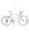
図1では、本発明による自転車用変速操作装置が備えられているマウンテンバイク1が示されている。この自転車には前輪2、後輪3、ペダル4、後輪3に設けられたスプロケット群7のいずれかにチェン5を掛け替えるためのディレーラ6、ブレーキ機構9等が備えられている。ハンドルに8取り付けられたグリップタイプの変速操作装置10が変速用ケーブル11を介してディレーラ6を操作する。
本明細書では、前方向、後ろ方向、横方向などの方向を示す表現が使われるが、これは自転車に対する方向である。従って、例えば、右方向は、ライダーが座席に座った状態での右方向である。
【0009】
図1に示されるとおり、典型的なマウンテンバイクではハンドル8は自転車1の横方向に延びるが、本発明による装置は、ハンドル8の先端に設けられる変速操作装置10に関するものであり、ハンドル自体の形状には限定されない。しかし、ハンドル8の先端は、長筒形状を有しているため、長手方向は明確に定義される。
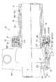
図2に示されるとおり、ハンドルの先端に取り付けられた変速用操作部である操作部16をハンドル8の長手方向に沿った第1軸芯X周りで回転させることにより、変速用ケーブル11を引き操作或いは緩め操作することによりディレーラ6を操作するのである。尚本実施例の変速装置では7段変速が可能である。
図3で示されるとおり、変速用ケーブル11を巻き取る巻き取り体18は第1軸芯X周りで回転するのであるが、偏向用プーリ21によりケーブル11が変速操作装置10の外では、ハンドル8に沿って延びるようにケーブル11の延びる方向が変更される。この偏向用プーリ21はブレーキ装置9のブレーキアーム9aを支持するブラケット部9bに取り付けられてあり、第1軸芯とは直角の第2軸芯Y周りで回転可能である。従って、変速用ケーブル11の巻き取り体18に巻かれている部分は、第1軸芯Xに対して垂直面内に位置しているが、変速操作装置10の外の部分は第1軸芯に沿って延びている。
【0010】
次に、変速操作装置10の構造について詳しく説明する。
自転車ハンドル8の右端部分に取り付けられ、リアディレーラ6を操作する変速操作装置10に対して説明するが、同様の変速操作装置をハンドルの左端に設けることもできる。
この変速操作装置10は、ハンドルに対し相対回転ができない状態で取り付けられた固定部材15と、この固定部材上で、第1軸芯X周りで回転可能の変速用操作部であるグリップ部16と、固定部材15と操作部16の両方に対してギヤ係合し、第1軸芯X周りで回転可能であると共に、第1軸芯に沿って移動可能であるアイドラーと呼ばれる中間体17と、この中間体と常にギヤ係合し、従って一体回動可能の巻き取り体18等を備えている。
【0011】
次に変速操作装置10の各部材について図3と図4を参照して説明する。
固定部材15は、好適には樹脂製であり、全体的にはハンドル8の外周にフィットする長筒形状を有している。筒状胴部15aの右端部には操作部16と接当する事により操作部16の右方向の移動を規制するための規制突起15bが設けられている。
この規制突起15bとは反対側で、中間体17と接当する部分には大径部分15cが設けられ、この大径部分15cの第1軸芯Xとは垂直で、中間体17と対向する面15sには固定部材ギヤ部151が設けられている。この第1軸芯Xとは垂直で中間体17に対向する面15sを固定部材の基準面15sと呼ぶ。固定部材ギヤ部151は固定部材15の基準面15sより第1軸芯方向に延びる複数のギヤ歯を有し、このギヤ歯の基準面15sよりの高さは15hで示されている。
中径筒状部15dがこの大径部分15cより更に中間体17の方向に延びており、中間体17の内径面17aと接当支持する面を形成している。この中径筒状部15dの外径は、筒状胴部15aの外径より大きく、大径部分15cの外径より小さい。
【0012】
グリップ部である操作部16は、上述された固定部材15に外嵌し、固定部材15に対して第1軸芯方向には移動不可能に、かつ、第1軸芯周りでは回転可能に支持されている。この操作部16は全体的には筒状の形状を有しており、中間体17と対向する部分には胴部16aより外径が大きい大径部分16bを有する。この大径部分6bの中間体17と対向する基準面16sにはギヤ部160が設けられている。このギヤ部160は操作部16の基準面16sより第1軸芯方向に延びる複数のギヤ歯を有し、このギヤ歯の基準面16sよりの高さは160hで表される。
次に、アイドラーと呼ばれる中間体17について説明する。この中間体17は全体的に環状をしており、この内径面17aは固定部材15の中径筒状部15dに対してスライド可能な状態で外嵌している。この中間体17の第1軸方向の幅は固定部材15の中径筒状部15dの第1軸方向の幅より小さく、第1軸方向に変位可能であり、且つ、第1軸周りで回転可能である。図3に示される巻き取り体18と中間体17の間に配置される板バネ20により中間体17は操作体16の方向に付勢されている。この中間体17の操作部16に対向する面には固定部材15のギヤ部151と係合する中間体第1ギヤ部170と操作部16のギヤ部160とギヤ係合する中間体第2ギヤ部171が備えられている。図4で示されるとおり、第1ギヤ部170は、第2ギヤ部171より径方向内径側に設けられている。
中間体17の巻き取り体と対向する側の周部17bの内面には巻き取り体18と係合するセレーション172が設けられている。このセレーション172は第1軸芯方向に延びており、その長さは172hで示されている。
【0013】
第1と第2ギヤ部170と171は、各々、第1軸芯とは垂直で、操作部16と対向する基準面17sより操作部16の方向に、第1軸芯に沿って延びているギヤ歯を有する。操作部16のギヤ部160と係合する中間体第2ギヤ部171のギヤ歯の歯丈171hは、固定部材15のギヤ部151と係合する中間体第2ギヤ部のギヤ歯の歯丈170hより大きい。
図5(a)では操作部16のギヤ部160と対向する中間体第2ギヤ部171の断面が、又、図5(b)では固定部材15のギヤ部151と対向する中間体第1ギヤ部170の断面が模式的に示されている。
図5(a)と図5(b)で明らかな通り、これらギヤ部のギヤ歯は各々第1軸芯Xに沿った方向に延びる面と、第1軸芯Xに対して傾斜した面を有する。即ち、中間体第1ギヤ部170のギヤ歯には第1軸芯Xに沿った方向に延びる位置保持面170aが備えられ、この面が、固定部材15のギヤ部151の対応する面151aと接当する。更に、第1軸芯Xに対して傾斜した第1カム面170bが中間体第1ギヤ部170のギヤ歯に備えられ、この面が固定部材の151bに対して接当する。
【0014】
又、中間体第2ギヤ部171のギヤ歯には第1軸芯Xに沿って延びた面171aと第1軸芯Xに対して傾斜した第2カム面171bが設けられている。この中間体第2ギヤ部171に対向する操作部16のギヤ部160のギヤ歯には中間体を回転駆動するための、第1軸芯に沿って延びた駆動面160aと、第2カム面171bと対応する面160bが備えられている。
尚、固定部材のギヤ歯、中間部材のギヤ歯、操作部のギヤ歯の歯長Wは全て変速段を一段分変速するに必要な変位と同じ長さに設定されている。
次に巻き取り体の形状を説明する。
図3に示されるとおり、巻き取り体の一番内径側の一部は固定部材15に外嵌しており、外周部には中間体17のセレーション172に対してギヤ係合する歯181が備えられている。この歯181の第1軸芯方向の幅は、中間体17のセレーション182の第1軸芯方向の幅より小さく、中間体17が第1軸芯に沿って変位しても、中間体17と巻き取り体18のギヤ係合が保持されるようになっている。
外周部のすぐ内径側で、巻き取り体の偏向用プーリ21に対向する面には偏向用プーリ21とギヤ係合するためのセレーション182が設けられている。巻き取り体18の大径部18aと基部18bの間には肩部18cが形成されており、この肩部18cにおいて変速用ケーブル11のインナーワイヤ11aが巻き取られる。図3に示される18dはインナーワイヤ11aの先端を巻き取り体18に連結する連結部である。
【0015】
次に、図3を用いて偏向用プーリ21の構造を説明する。
偏向用プーリ21はブレーキ装置のブラケット9bに対して第2軸芯周りで回転可能に固定ネジ22により保持されている。この第2軸芯は第1軸芯に対して直角である。インナーワイヤ11aの巻き取り体18に巻き取られた部分は第1軸芯とは垂直の面に位置するが、偏向用プーリ21により、このインナーワイヤ11aの変速操作装置の外の部分をハンドルの長手方向に延ばすことができる。
偏向用プーリ21は全体的に円盤状をしており、この周部には巻き取り体のセレーション182と係合する係合歯21aが設けられている。又、この周部よりすぐ内径側に、第2軸芯方向に延びる肩部21bが形成されており、この肩部21bにインナーワイヤ21bが周接するのである。
この偏向用プーリ21には変速段を表示する表示部が設けられている。この表示部は図2に示されるとおり、偏向用プーリ21の側面に書かれた変速段を表す数字であり、これが固定部23に備えられたカバー25に設けられた窓より見ることができる。この窓と、変速段を示す数字は変速段に対応する数字を表示できるように位置調整がなされている。
【0016】
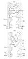
次に図6と図7を参照して本発明による変速操作装置、特に中間体17と固定部15と操作部のそれぞれのギヤ部で構成されるクラッチの部分に焦点を当てて実際の動きを説明する。ただし簡単のために図6と7ではギヤ歯の形状を簡略化して図示している。
図6では操作部16を巻き取り方向に操作する際にこれらの部分が移動する様子を図6(a)から(d)の順に示されている。
先ず、操作部16を、巻き取り体18の巻き取り方向に対応する一方方向(図6中矢印D1で示される方向)に回転させると、操作部部16のギヤ部160の駆動面160aが中間体17の第2ギヤ部171の面171と接当し中間体17を第1軸芯X周りに回転する。そうすると、中間体17の第1ギヤ部170と第2ギヤ部171は一体的に形成されているため、第1ギヤ部170が、固定部材151に対して移動する。
【0017】
図6(b)と(c)で示されるとおり、第1ギヤ部の第1カム面170bにより、巻き取り体18の巻き取り方向への回動と共に、中間体170が第1軸方向に変位する。そして、更に操作部160を巻き取り方向に回転すると、図6(d)に示されるとおり中間体17の第1ギヤ部のギヤ歯は固定部材15のギヤ歯を乗り越え、中間体17が、固定部材15に対し1変速段分w移動した位置で再び固定部材15に対し係止された状態になる。このとき中間体17の位置保持面170aがこれに対応する固定部材15の面151aと接当して中間体17が固定部材15に対して位置保持される。
この際、中間体第2ギヤ部171と操作部16のギヤ部160の係合部分においては、中間体第2ギヤ部171の歯丈171hが、中間体第1ギヤ部170のギヤ歯の歯丈170hよりも高いため、中間体第1ギヤ部170のギヤ歯が固定部材15のギヤ歯を乗り越えても、中間体第2ギヤ部171のギヤ歯は操作部16のギヤ部160の歯を乗り越えず、同じ歯同士で係止している。すなわち、中間体17の操作部16に対する相対位置は操作部16の操作以前と変化はない。
【0018】
中間体17は巻き取り体18と常に係合しているため、巻き取り体18は中間体17とともに固定部材15に対して1変速段分w移動する。
次に操作部16を巻き取り方向と反対方向の巻き戻し方向へ回転操作した際の、固定部材15に対する中間体17と巻き取り体18の移動について図7を参照して説明する。
図7では操作部16を巻き取り方向に操作する際にこれらの部分が移動する様子を図6(a)から(d)の順に示されている。
操作部16を図7においてD2で示される上記の一方方向とは逆の方向へ回動すると、中間体17の第2ギヤ部に設けられた第2カム面171bがこれに対応する操作部のギヤ部160と摺動し、操作部16がD2の方向へ変位すると共に、中間体17は第1軸芯方向に沿って操作部16より離れる方向へ移動する。この際、中間体17の位置保持面170aは固定部材15の対応する151aと係止しているため、位置保持面170aは固定部材15の対応する面151aに対してスライドするのみであり、従って、中間部材17はこの時点では第1軸芯周りの回転変位はしない。更に操作部16をD2で示される方向に回転すると、中間体第1ギヤ部170のギヤ歯の歯丈170hが中間体第2ギヤ部171の歯丈171hよりも低いため、図7cで示されるとおり、中間体第1ギヤ部170のギヤ歯が、これに対応する固定部材15のギヤ歯を乗り越える。この際、中間体17は巻き取り体18を介して、巻き戻し方向(D2で示される方向)へ付勢されているため、図7dで示されるとおり中間体17は、固定部材15に対し一変速段分(w)巻き戻し方向へ移動する。この際、中間体第2ギヤ部171は操作部16のギヤ部160に対し、一旦は離れる方向へ移動するが、中間体第1ギヤ部170のギヤ歯が固定部材15のギヤ歯を乗り越えた際、再度同じ歯と係合する。
【図面の簡単な説明】
【図1】本発明による変速操作装置を備えた自転車の斜視図
【図2】本発明による変速操作装置の斜視図
【図3】本発明による変速操作装置の重要部分を示す断面図
【図4】本発明による変速操作装置の重要部分の位置関係を示す一部断面図
【図5】中間部と固定部材と操作部のそれぞれのギヤ部の形状を示す断面図
【図6】図5に示されたギヤ部の巻き取り時における動きを示す断面図
【図7】図5に示されたギヤ部の巻き戻し時における動きを示す断面図
【符号の説明】
8 ハンドル
9b ブレーキブラケット
10 変速操作装置
11 変速操作用ケーブル
11a インナーケーブル
15 固定部材
16 操作部
17 中間部
18 巻き取り体
21 回転体[0001]
BACKGROUND OF THE INVENTION
The present invention relates to a grip-type operating device for a bicycle transmission.
[0002]
[Prior art]
In some cases, the take-up body of the cable for speed change operation is wound or unwound by an operation portion that is rotatable around an axis extending in the longitudinal direction of the handle tip in the vicinity of the handle tip. After performing the winding operation in this way, it is necessary to position the winding body at a position corresponding to the selected gear position.
As a positioning method, there is a method of simply using frictional resistance, or a concave portion at the shift position on the fixed member side as disclosed in JP-A-3-176290, and a convex portion on the operating member side is locked to this. There are known a method for holding the positionand a one-weiler check mechanism.
[0003]
[Problems to be solved by the invention]
In such a positioning mechanism using frictional resistance or engagement between the concave and convex portions, it is necessary to increase the engagement force in order to reliably position the winding body at the position corresponding to the selected gear position. However, this requires a large amount of force for operation.
In addition, the ratchet mechanism or the like has a large number of parts or needs to use many metal parts, and there is room for improvement in terms of cost.
[0004]
[Means for Solving the Problems]
In order to solve the above-described problem, in the bicycle speed change operation device according to the present invention, between the operating portion and the winding body, the winding body and the first shaft core are integrally rotated and fixed. There is provided an intermediate body capable of relative movement in the first axial direction between an engagement position engaged with the member and a non-engagement position where the engagement is released, And a driving surface that drives the intermediate body in the one direction by contact with the intermediate body when rotated in the one direction, and the intermediate body contacts the fixed portion, A first cam surface that converts rotation of the intermediate body in the one direction into displacement of the intermediate body into the disengaged position; and a contact with the fixing member when the intermediate body is in the engaged position. And a plurality of position holding surfaces that prevent rotation of the intermediate body around the first axis. To provide a rolling vehicle for shifting apparatus.
[0005]
With the above structure, the intermediate body that rotates integrally with the winding body comes into contact with the fixing member, so that the winding body can be reliably fixed to the fixing member via the intermediate body, and the operation unit can be fixed in one direction. This fixing can be easily released by the first cam surface that converts the rotation of the intermediate member into the direction in which the intermediate member is disengaged from the fixing member.
In a preferred embodiment of the present invention, it is preferable that the intermediate body is provided with a second cam surface that converts the rotation of the operation portion in the other direction into the displacement of the intermediate body to the disengaged position. With this configuration, the positioning of the winding body with respect to the fixing member is released even when the operation portion is rotated in the other direction, and the shifting in multiple directions can be performed in the same manner.
[0006]
In a preferred embodiment of the present invention, the first cam surface and the second cam surface are provided on the same plane extending perpendicular to the first axis, and are shifted in a radial direction with respect to the first axis. It is preferable to provide each in an arc shape. In this way, the intermediate body can be made compact, and the entire speed change operation device can be miniaturized.
Preferably, the driving surface of the operation unit and the position holding surface of the intermediate body are both configured to extend in the first axial direction, so that the circumferential force on the first axial axis can be prevented. A surface that can cope with the most efficiently can be formed, and the position holding of the intermediate body with respect to the fixing member and the driving of the operation section with respect to the intermediate body are ensured.
[0007]
Further, according to a preferred embodiment, the height of the drive surface of the operation portion in the first axial direction is made higher than the height of the position holding surface in the first axial direction, thereby making the operation portion a first axis. When the intermediate body is rotated around the core and the intermediate body is displaced in the first axial direction, the intermediate body can be disengaged from the fixing member without releasing the engagement of the intermediate body from the operation portion. Thus, the operation unit always rotates integrally with the winding body via the intermediate body, and can be fixed at different positions with respect to the fixing member.
Other features and advantages of the present invention will become apparent from the following description of embodiments of the present invention using the drawings.
[0008]
DETAILED DESCRIPTION OF THE INVENTION
Embodiments of the present invention will be described with reference to the drawings.
FIG. 1 shows a
In this specification, expressions indicating directions such as the front direction, the rear direction, and the lateral direction are used, which are directions with respect to the bicycle. Therefore, for example, the right direction is the right direction when the rider is sitting on the seat.
[0009]
As shown in FIG. 1, in a typical mountain bike, the
As shown in FIG. 2, the
As shown in FIG. 3, the
[0010]
Next, the structure of the speed
Although a description will be given of the speed
The speed
[0011]
Next, each member of the speed
The
A large-
The intermediate diameter
[0012]
The
Next, the
A
[0013]
The first and
5A shows a cross section of the intermediate
As is apparent from FIGS. 5A and 5B, the gear teeth of these gear portions each have a surface extending in the direction along the first axis X and a surface inclined with respect to the first axis X. Have. In other words, the gear teeth of the intermediate
[0014]
The gear teeth of the intermediate
Note that the tooth lengths W of the gear teeth of the fixed member, the gear teeth of the intermediate member, and the gear teeth of the operation unit are all set to the same length as the displacement required to shift the shift stage by one step.
Next, the shape of the wound body will be described.
As shown in FIG. 3, a part of the winding body on the innermost diameter side is externally fitted to the fixing
A
[0015]
Next, the structure of the
The
The
The
[0016]
Next, referring to FIG. 6 and FIG. 7, focusing on the speed change device according to the present invention, particularly the clutch portion composed of the
FIG. 6 shows the order in which these portions move when operating the
First, when the
[0017]
As shown in FIGS. 6B and 6C, the
At this time, in the engaging portion of the intermediate body
[0018]
Since the
Next, the movement of the
FIG. 7 shows the order in which these portions move when operating the
When the
[Brief description of the drawings]
FIG. 1 is a perspective view of a bicycle equipped with a speed change operation device according to the present invention. FIG. 2 is a perspective view of a speed change operation device according to the present invention. FIG. 5 is a partial cross-sectional view showing the positional relationship of important parts of the speed change operation device according to the present invention. FIG. 5 is a cross-sectional view showing the shapes of the gear portions of the intermediate portion, the fixing member, and the operation portion. FIG. 7 is a cross-sectional view showing the movement of the gear unit during rewinding. FIG. 7 is a cross-sectional view showing the movement of the gear unit shown in FIG. 5 during rewinding.
8
Claims (5)
Translated fromJapanese前記固定部材に対して、前記ハンドルの先端領域の長手方向に沿う第1軸芯周りで一方方向と他方方向に回動可能の操作部と、
変速用ケーブルを引き戻し操作するために前記操作部の回動に伴って前記第1軸芯周りで回動可能の巻き取り体を有する自転車用変速操作装置において、
前記操作部と前記巻き取り体の間には、前記巻き取り体と前記第1軸芯周りで一体回転し、かつ、前記固定部材材に対して係合している係合位置と、係合が解除されている非係合位置の間で前記第1軸芯方向の相対移動が可能の中間体が設けられ、前記操作部は、前記一方方向に回転した際に前記中間体との接当により前記中間体を前記一方方向に駆動する駆動面を有し、
前記中間体は、前記固定部材に対して接当する事により、前記中間体の前記一方方向の回転を前記中間体の前記非係合位置への変位に変換する第1カム面と、前記中間体が係合位置にある際に前記固定部材材に対して接当することにより前記中間体の前記第1軸芯周りの回転を阻止する位置保持面を有することを特徴とする自転車用変速操作装置。A fixing member that can be fixed to the handle of the bicycle;
An operation unit that is rotatable in one direction and the other direction around the first axis along the longitudinal direction of the distal end region of the handle with respect to the fixing member;
In a bicycle shift operation device having a winding body that is rotatable around the first axis in accordance with the rotation of the operation portion in order to pull back the shift cable.
Between the operation portion and the winding body, an engagement position that rotates integrally around the winding body and the first axis and engages with the fixing member material, and an engagement An intermediate body capable of relative movement in the first axis direction is provided between the disengaged positions where the operation is released, and the operation portion is in contact with the intermediate body when rotated in the one direction. A driving surface for driving the intermediate body in the one direction,
The intermediate body is in contact with the fixing member, thereby converting a rotation of the intermediate body in the one direction into a displacement of the intermediate body into the disengaged position; and the intermediate body A bicycle shift operation characterized by having a position holding surface that prevents rotation of the intermediate body around the first axis by contacting the fixing member when the body is in the engaged position. apparatus.
Priority Applications (6)
| Application Number | Priority Date | Filing Date | Title |
|---|---|---|---|
| JP13651896AJP3678496B2 (en) | 1996-05-30 | 1996-05-30 | Bicycle shifting operation device |
| TW086105751ATW334407B (en) | 1996-05-30 | 1997-04-30 | Gearshift apparatus for bicycles |
| US08/854,520US5921139A (en) | 1996-05-30 | 1997-05-13 | Bicycle shift control device |
| DE69714346TDE69714346T2 (en) | 1996-05-30 | 1997-05-23 | Control device for a bicycle gear shift |
| EP97303534AEP0810150B1 (en) | 1996-05-30 | 1997-05-23 | Bicycle shift control device |
| CN97105503ACN1071657C (en) | 1996-05-30 | 1997-05-30 | Speed changing operating device for bicycle |
Applications Claiming Priority (1)
| Application Number | Priority Date | Filing Date | Title |
|---|---|---|---|
| JP13651896AJP3678496B2 (en) | 1996-05-30 | 1996-05-30 | Bicycle shifting operation device |
Publications (2)
| Publication Number | Publication Date |
|---|---|
| JPH09315378A JPH09315378A (en) | 1997-12-09 |
| JP3678496B2true JP3678496B2 (en) | 2005-08-03 |
Family
ID=15177057
Family Applications (1)
| Application Number | Title | Priority Date | Filing Date |
|---|---|---|---|
| JP13651896AExpired - Fee RelatedJP3678496B2 (en) | 1996-05-30 | 1996-05-30 | Bicycle shifting operation device |
Country Status (6)
| Country | Link |
|---|---|
| US (1) | US5921139A (en) |
| EP (1) | EP0810150B1 (en) |
| JP (1) | JP3678496B2 (en) |
| CN (1) | CN1071657C (en) |
| DE (1) | DE69714346T2 (en) |
| TW (1) | TW334407B (en) |
Families Citing this family (44)
| Publication number | Priority date | Publication date | Assignee | Title |
|---|---|---|---|---|
| US6453766B1 (en) | 1998-11-20 | 2002-09-24 | Shimano, Inc. | Force transfer mechanism for a bicycle transmission control cable |
| DE59907550D1 (en)* | 1999-07-15 | 2003-12-04 | Dirk Tielbuerger | Agricultural machine |
| US6467368B1 (en)* | 1999-08-03 | 2002-10-22 | National Science Council Of Republic Of China | Hand operated bicycle gear transmission device |
| US6204752B1 (en) | 1999-11-24 | 2001-03-20 | Shimano Inc. | Bicycle display unit with backlight |
| DE10009214A1 (en)* | 2000-02-26 | 2001-08-30 | Sram De Gmbh | Gear selector unit for bicycle; manual operation unit for control unit, display unit with indicator and gear device, so that arc traced by indicator is smaller than arc traced by operation unit |
| USD436898S1 (en) | 2000-02-29 | 2001-01-30 | Shimano Inc. | Bicycle display |
| US6265967B1 (en) | 2000-02-29 | 2001-07-24 | Shimano Inc. | Display device for bicycle |
| US6331089B1 (en) | 2000-02-29 | 2001-12-18 | Shimano, Inc. | Mounting device for bicycle component |
| USD443562S1 (en) | 2000-02-29 | 2001-06-12 | Shimano Inc. | Bicycle display with mounting assembly |
| DE10025887A1 (en)* | 2000-05-25 | 2001-11-29 | Sram De Gmbh | Integrated twist grip switch |
| KR20010110061A (en)* | 2000-05-30 | 2001-12-12 | 마재열 | Apparatus for controlling a speed changing apparatus for bicycles |
| US6595894B2 (en) | 2001-03-09 | 2003-07-22 | Shimano (Singapore) Private Limited | Shift control device |
| US6718844B2 (en) | 2002-02-13 | 2004-04-13 | Shimano, Inc. | Twist-grip shift control device for a bicycle |
| US7150205B2 (en)* | 2002-04-04 | 2006-12-19 | Shimano, Inc. | Handgrip shifter for a bicycle |
| US6729203B2 (en) | 2002-06-04 | 2004-05-04 | Sram Corporation | Bicycle gear shifter having separate shift control members for cable pull and release |
| KR20040045646A (en)* | 2002-11-25 | 2004-06-02 | 오종수 | Apparatus for changing speed of bicycles |
| FR2849826B1 (en)* | 2003-01-15 | 2005-03-11 | Etcetera | PREDETERMINED DEVELOPMENT SPEED SELECTOR, IN PARTICULAR FOR CYCLE |
| US7290462B2 (en)* | 2003-08-11 | 2007-11-06 | Shimano, Inc. | Bicycle twist-grip shift control device with parallel gearing |
| US20060129152A1 (en)* | 2004-12-10 | 2006-06-15 | Shipp John I | Absorbable Anchor for Hernia Mesh Fixation |
| US7281489B2 (en)* | 2004-04-29 | 2007-10-16 | Shimano, Inc. | Bicycle transmission gear indicating device |
| US7448297B2 (en)* | 2004-08-04 | 2008-11-11 | Shimano (Singapore) Pte., Ltd | Mountable bicycle structure |
| TWI261038B (en)* | 2004-08-11 | 2006-09-01 | Bo-Cheng Chen | Bicycle gear-shifting handgrip |
| US7340975B2 (en)* | 2004-12-21 | 2008-03-11 | Shimano, Inc. | Bicycle control apparatus with a position setting idler member |
| US7650813B2 (en)* | 2005-05-19 | 2010-01-26 | Shimano Inc. | Position control mechanism for bicycle control device |
| US7882762B2 (en)* | 2006-01-30 | 2011-02-08 | Fallbrook Technologies Inc. | System for manipulating a continuously variable transmission |
| EP1996442A2 (en)* | 2006-03-20 | 2008-12-03 | Graco Children's Products Inc. | Foldable stroller having retractable cup holder |
| US9446813B2 (en)* | 2006-03-23 | 2016-09-20 | Sram, Llc | Bicycle shifter |
| US7757582B2 (en)* | 2006-12-20 | 2010-07-20 | Shimano (Singapore) Pte., Ltd. | Bicycle component mounting structure |
| US8777788B2 (en)* | 2007-02-08 | 2014-07-15 | Shimano Inc. | Bicycle component positioning device |
| JP2008230323A (en)* | 2007-03-19 | 2008-10-02 | Shimano Singapore Pte Ltd | Positioning device for speed changing system of bicycle |
| US8016705B2 (en)* | 2007-04-19 | 2011-09-13 | Shimano Inc. | Bicycle component positioning device |
| US9334020B2 (en)* | 2007-04-26 | 2016-05-10 | Shimano Inc. | Bicycle component positioning device |
| US20080284126A1 (en)* | 2007-05-16 | 2008-11-20 | Smith Stephen T | Adaptive brake and shift mechanism for a bicycle |
| US8403800B2 (en) | 2010-07-28 | 2013-03-26 | The Gates Corporation | Shift mechanism for a planetary gear transmission |
| US8978511B2 (en)* | 2010-11-09 | 2015-03-17 | Shimano Inc. | Position control mechanism |
| US9033833B2 (en) | 2011-01-28 | 2015-05-19 | Paha Designs, Llc | Gear transmission and derailleur system |
| US9327792B2 (en) | 2011-01-28 | 2016-05-03 | Paha Designs, Llc | Gear transmission and derailleur system |
| US10207772B2 (en) | 2011-01-28 | 2019-02-19 | Paha Designs, Llc | Gear transmission and derailleur system |
| JP2013010481A (en)* | 2011-06-30 | 2013-01-17 | Nippon Seiki Co Ltd | Shift operation device |
| US9651138B2 (en) | 2011-09-30 | 2017-05-16 | Mtd Products Inc. | Speed control assembly for a self-propelled walk-behind lawn mower |
| US9016164B2 (en)* | 2012-10-24 | 2015-04-28 | Shimano (Singapore) Pte. Ltd. | Bicycle control device |
| US20140252746A1 (en)* | 2013-03-06 | 2014-09-11 | Specialized Bicycle Components, Inc. | Bicycle electronic display and shift lever mount |
| EP3261689B1 (en) | 2015-02-27 | 2019-04-10 | Novo Nordisk A/S | Drug delivery device with dose reset mechanism |
| US10889346B2 (en) | 2017-08-18 | 2021-01-12 | Shimano Inc. | Electric twist-grip operating device |
Family Cites Families (11)
| Publication number | Priority date | Publication date | Assignee | Title |
|---|---|---|---|---|
| FR1064563A (en)* | 1952-10-20 | 1954-05-14 | Gear change control device for bicycles, tandems and the like | |
| US3633437A (en)* | 1969-07-31 | 1972-01-11 | Takuo Ishida | Hand control device for speed change gear mechanism of a bicycle |
| US3665775A (en)* | 1970-10-06 | 1972-05-30 | Kenneth G Freeman | Ratchet control mechanism |
| US3874248A (en)* | 1973-07-18 | 1975-04-01 | Foote Foundry Co J B | Shift mechanism for transmissions |
| US4900291B1 (en)* | 1988-01-06 | 2000-04-25 | Sram Corp | Bicycle gear shifting method and apparatus |
| DE69008298T2 (en) | 1989-10-20 | 1994-08-04 | Campagnolo Srl | Twist grip device for actuating the gear shifts of a bicycle. |
| JPH04260889A (en)* | 1991-02-13 | 1992-09-16 | Maeda Kogyo Kk | Speed change operating device for bicycle |
| US5197927B1 (en)* | 1991-03-20 | 2000-10-17 | Sram Corp | Bicycle derailleur cable actuating system |
| JPH06199270A (en)* | 1992-12-28 | 1994-07-19 | Mori San Tsuaa:Kk | Gear shift device for bicycle |
| US5799542A (en)* | 1995-10-11 | 1998-09-01 | Shimano, Inc. | Bicycle shift control device |
| US5673594A (en)* | 1996-01-03 | 1997-10-07 | Industrial Technology Research Institute | Speed change lever apparatus for use in bicycles |
- 1996
- 1996-05-30JPJP13651896Apatent/JP3678496B2/ennot_activeExpired - Fee Related
- 1997
- 1997-04-30TWTW086105751Apatent/TW334407B/ennot_activeIP Right Cessation
- 1997-05-13USUS08/854,520patent/US5921139A/ennot_activeExpired - Lifetime
- 1997-05-23DEDE69714346Tpatent/DE69714346T2/ennot_activeExpired - Lifetime
- 1997-05-23EPEP97303534Apatent/EP0810150B1/ennot_activeExpired - Lifetime
- 1997-05-30CNCN97105503Apatent/CN1071657C/ennot_activeExpired - Fee Related
Also Published As
| Publication number | Publication date |
|---|---|
| TW334407B (en) | 1998-06-21 |
| CN1071657C (en) | 2001-09-26 |
| EP0810150B1 (en) | 2002-07-31 |
| EP0810150A2 (en) | 1997-12-03 |
| US5921139A (en) | 1999-07-13 |
| DE69714346D1 (en) | 2002-09-05 |
| JPH09315378A (en) | 1997-12-09 |
| EP0810150A3 (en) | 2000-04-26 |
| CN1167715A (en) | 1997-12-17 |
| DE69714346T2 (en) | 2003-04-03 |
Similar Documents
| Publication | Publication Date | Title |
|---|---|---|
| JP3678496B2 (en) | Bicycle shifting operation device | |
| JP3850808B2 (en) | Bicycle shift control device | |
| JP3766389B2 (en) | Bicycle shift control device | |
| EP2174862B1 (en) | Bicycle control device | |
| US5094120A (en) | Bicycle speed change lever assembly | |
| EP1746022B1 (en) | Bicycle shift position control mechanism | |
| EP1440878B1 (en) | Apparatus for shifting a bicycle transmission | |
| EP0790175A1 (en) | Bicycle shift levers which surround a handlebar | |
| EP0605741B1 (en) | Change gear operation device for bicycle | |
| JP2007001572A (en) | Integrated control device for derailer and brake of bicycle | |
| JPH07259985A (en) | Rotary hand grip type cable actuator | |
| JP2006321479A (en) | Control device for bicycle and its position control mechanism | |
| US9056648B2 (en) | Bicycle component positioning device | |
| EP1619113A2 (en) | Shift control device for a bicycle transmission | |
| JP3423288B2 (en) | Bicycle transmission shift device | |
| US8528442B2 (en) | Bicycle component positioning device | |
| JPS58191682A (en) | Variable speed mechanism for bicycle | |
| JP2007076510A (en) | Gear shift operation device for bicycle | |
| JP2005059844A (en) | Twist grip shift control device for bicycle using parallel gears | |
| JP2017013780A (en) | Actuation device for a control cable for a bicycle gearshift | |
| WO1993018961A1 (en) | Gear shifter for bicycle | |
| WO1993019977A1 (en) | Gear shifter for bicycle | |
| JP2006096333A (en) | Engagement force reduction device for engagement member of bicycle part | |
| JP2006131218A (en) | Bicycle shift operating device | |
| US7849760B2 (en) | Speed changer with pre-determined gears, particularly for cycles |
Legal Events
| Date | Code | Title | Description |
|---|---|---|---|
| A131 | Notification of reasons for refusal | Free format text:JAPANESE INTERMEDIATE CODE: A131 Effective date:20050120 | |
| A521 | Request for written amendment filed | Free format text:JAPANESE INTERMEDIATE CODE: A523 Effective date:20050322 | |
| TRDD | Decision of grant or rejection written | ||
| A01 | Written decision to grant a patent or to grant a registration (utility model) | Free format text:JAPANESE INTERMEDIATE CODE: A01 Effective date:20050421 | |
| A61 | First payment of annual fees (during grant procedure) | Free format text:JAPANESE INTERMEDIATE CODE: A61 Effective date:20050510 | |
| R150 | Certificate of patent or registration of utility model | Free format text:JAPANESE INTERMEDIATE CODE: R150 | |
| FPAY | Renewal fee payment (event date is renewal date of database) | Free format text:PAYMENT UNTIL: 20090520 Year of fee payment:4 | |
| FPAY | Renewal fee payment (event date is renewal date of database) | Free format text:PAYMENT UNTIL: 20090520 Year of fee payment:4 | |
| FPAY | Renewal fee payment (event date is renewal date of database) | Free format text:PAYMENT UNTIL: 20100520 Year of fee payment:5 | |
| FPAY | Renewal fee payment (event date is renewal date of database) | Free format text:PAYMENT UNTIL: 20110520 Year of fee payment:6 | |
| FPAY | Renewal fee payment (event date is renewal date of database) | Free format text:PAYMENT UNTIL: 20110520 Year of fee payment:6 | |
| FPAY | Renewal fee payment (event date is renewal date of database) | Free format text:PAYMENT UNTIL: 20120520 Year of fee payment:7 | |
| FPAY | Renewal fee payment (event date is renewal date of database) | Free format text:PAYMENT UNTIL: 20130520 Year of fee payment:8 | |
| FPAY | Renewal fee payment (event date is renewal date of database) | Free format text:PAYMENT UNTIL: 20140520 Year of fee payment:9 | |
| R250 | Receipt of annual fees | Free format text:JAPANESE INTERMEDIATE CODE: R250 | |
| LAPS | Cancellation because of no payment of annual fees |