JP3678404B2 - Video information processing device - Google Patents
Video information processing deviceDownload PDFInfo
- Publication number
- JP3678404B2 JP3678404B2JP2000139253AJP2000139253AJP3678404B2JP 3678404 B2JP3678404 B2JP 3678404B2JP 2000139253 AJP2000139253 AJP 2000139253AJP 2000139253 AJP2000139253 AJP 2000139253AJP 3678404 B2JP3678404 B2JP 3678404B2
- Authority
- JP
- Japan
- Prior art keywords
- video
- identification information
- blinking
- information
- light source
- Prior art date
- Legal status (The legal status is an assumption and is not a legal conclusion. Google has not performed a legal analysis and makes no representation as to the accuracy of the status listed.)
- Expired - Fee Related
Links
Images


Classifications
- G—PHYSICS
- G06—COMPUTING OR CALCULATING; COUNTING
- G06V—IMAGE OR VIDEO RECOGNITION OR UNDERSTANDING
- G06V10/00—Arrangements for image or video recognition or understanding
- G06V10/40—Extraction of image or video features
Landscapes
- Engineering & Computer Science (AREA)
- Physics & Mathematics (AREA)
- General Physics & Mathematics (AREA)
- Multimedia (AREA)
- Theoretical Computer Science (AREA)
- Closed-Circuit Television Systems (AREA)
- Studio Devices (AREA)
Description
Translated fromJapanese【0001】
【発明の属する技術分野】
本発明は、被写体の識別情報をもとに映像を処理する映像情報処理装置に関する。
【0002】
【従来の技術】
従来、赤外線やギガヘルツの周波数帯域を用いたワイアレス情報送受信方法が一般的に用いられており、テレビやビデオデッキ、無線LANなどに広く応用されている。また、Bluetooth という近距離無線の規格も出来つつある。
【0003】
一方、映像を印画紙上の化学反応で記録するのではなく、CCD等の固体撮像素子が取り込んだ映像データを電子メモリ素子に記録するディジタルカメラも広く用いられている。
【0004】
【発明が解決しようとする課題】
しかしながら、業務や趣味として写真撮影を行う場合、その撮影枚数が多くなればなるほど後日の整理に手間がかかり、日数を経てしまうと映像の内容を確認するためには、その映像そのものを閲覧しなければ判断できないという問題がある。一方、1枚の映像中に興味ある被写体が複数ある場合、それぞれに注釈を加える方法が提案されている(特開平6−343146号公報)が、その作業にも多少の手間がかかる。
【0005】
また、従来の監視カメラはカメラ映像を人間が目視で見張って救助の要否を判断しており、被写体の側から自発的に、かつ他人に知られずに救助を要請することは不可能であったために、通報すれば危害を加えるという脅迫を受けている被害者は、監視カメラの前にありながら加害者に知られずに通報することができなかった。
【0006】
さらに、カメラによる写真撮影に不慣れな利用者は、複数の被写体を撮影範囲におさめるのに困難を感じることもある。また、写真撮影を行う際には、撮影と無関係な被写体の中に、撮影されることを好まないものが存在することもあり、プライバシーと関連して問題となる。
【0007】
本発明は斯かる実情に鑑み、上記のような映像整理を容易に実現できるようなカメラを実現すること、および映像にその説明となる情報を多重化して記録するカメラを実現すること、また、周囲の人間に知られることなく被写体の意思を伝達する機能を持つカメラを実現すること、さらに、所望の被写体が確実に撮影範囲に入っていることを容易に確認できるカメラを実現することを目的とする。
【0008】
【課題を解決するための手段】
本発明においては、映像を入力するための入力手段と、点滅光源による点滅パターンに対応する識別情報を記憶してなる記憶手段と、この記憶手段に記憶された識別情報をもとに、前記入力手段によって入力された映像内で点滅する光源の点滅パターンに対応する識別情報に変換するための点滅情報変換手段と、この点滅情報変換手段によって変換された識別情報を、入力された前記映像とともに出力するための出力手段とを備えることを特徴とする。
【0009】
これにより識別情報がURLの場合、後日、その写真内の被写体をコンピュータ画面内でクリックすることにより、被写体に応じたインターネット・ページを表示することができる「クリッカブル・イメージ(clickable image )」を自動作成でき、撮影と別に映像に情報を付加する手間が省略される。
【0010】
また、映像を入力するための入力手段と、点滅光源による点滅パターンに対応する識別情報を記憶してなる記憶手段と、この記憶手段に記憶された識別情報をもとに、前記入力手段によって入力された映像内で点滅する光源の点滅パターンに対応する識別情報に変換するための点滅情報変換手段と、この点滅情報変換手段によって変換された識別情報を、入力された前記映像とともに出力するための出力手段とを備えることを特徴とする。
【0011】
これにより、被写体が発する識別情報が「写真撮影を好まない」というものである場合には画面の一部または全部を修正する。これにより写真撮影を好まない被写体のプライバシーを守ることができる。撮影は許容するが、自分が映った写真を後日送付してほしい場合や、自分が映ったことによって課金を行いたい場合なども、本発明の映像情報処理装置を用いて実現できる。
【0012】
さらに、映像を入力するための入力手段と、点滅光源による点滅パターンに対応する識別情報を記憶してなる記憶手段と、この記憶手段に記憶された識別情報をもとに、前記入力手段によって入力された映像内で点滅する光源の点滅パターンに対応する識別情報に変換するための点滅情報変換手段と、この点滅情報変換手段によって変換された識別情報に応じて、あらかじめ設定されたメッセージを出力するためのメッセージ出力手段とを備えることを特徴とする。
【0013】
これにより、「SOS」を意味する識別情報を発する被写体が撮影範囲にある場合には、救助機関や警察などに自動的に通報する。これにより銀行のATM(現金自動預出機)やコンビニエンス・ストア、市街地などに設置されている防犯カメラがSOS(救助要請)識別情報を読み取れば、発信源の脅威の原因(強盗や痴漢など)に察知されることなく救助機関に自動通報することができる。
【0014】
さらに、映像を入力するための入力手段と、点滅光源による点滅パターンに対応する識別情報を記憶してなる記憶手段と、この記憶手段に記憶された識別情報をもとに、前記入力手段によって入力された映像内で点滅する光源の点滅パターンに対応する識別情報に変換するための点滅情報変換手段と、前記映像内での点滅光源の位置を検出するための位置検出手段と、検出すべき被写体を示す識別情報を記憶してなる被写体記憶手段と、前記点滅情報変換手段によって変換された識別情報であって、前記被写体記憶手段に記憶された識別情報を有する被写体の位置を、前記位置検出手段によって検出された点滅光源の位置をもとに検出する被写体検出手段とを備えることを特徴とする。
【0015】
これにより、本発明の映像情報処理装置にあらかじめ撮影したい(したくない)被写体が発する識別情報を登録しておけば、撮影したい(したくない)被写体が撮影範囲に入っているか否かをカメラが感知し、撮影範囲に入っていない(入っている)場合には、そのことを撮影者に伝える。あるいは、撮影したい(したくない)被写体が撮影範囲に入ったときに(出たときに)自動的に撮影を行う。これにより写真撮影に不慣れな撮影者が写真を撮影する場合にも、目的の被写体を正しくフレーム内におさめた写真を簡単に撮影することができる。
【0016】
また、被写体の識別情報をもとに映像を処理する映像処理装置に対し、被写体ごとの識別情報を発信するための発信装置であって、被写体の識別情報を示す点滅パターンを記憶してなる点滅パターン記憶手段と、この点滅パターン記憶手段に記憶された点滅パターンを所定のタイミングで発光するための発光手段とを有することを特徴とする。この発信機により、映像処理装置に対し識別情報を発信することができる。
【0017】
【発明の実施の形態】
以下、本発明の実施の形態を図示例と共に説明する。本発明の映像情報処理装置について、図面に即して説明する。なお、以下では便宜的にカメラと表現することもあるが、本発明の映像情報処理装置の形態は、必ずしも写真カメラと一体になったものに限定されない。例えば、カメラがパーソナル・コンピュータに接続されており、識別情報の読み取りなどの計算処理をパーソナル・コンピュータ側で行ってもよいし、カメラが撮影映像を無線または有線通信で遠隔地に送信する機能を持っており、映像を受信したパーソナル・コンピュータなどで識別情報の読み取りなどの計算処理を行ってもよい。
【0018】
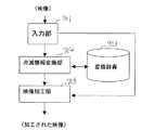
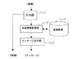
図1は本発明の第1の実施例の構成を示す図である。映像情報はカメラのCCD等の入力部101から入力され、処理用映像と表示・記録用映像に分けられる。この時点における処理用映像と表示・記録用映像の内容は同一のものである。
【0019】
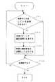
処理用映像は、点滅情報変換部104に送られる。点滅情報変換部104では、図2のフローチャートにあるように、数秒分の映像をもとに、点滅情報変換部104は映像中に所定の規則に則した点滅を行う光源があるかどうかを判定する(S301)。
【0020】
なお、所定の規則とは、例えばテレビジョン受像機やビデオテーププレイヤー、あるいはエアコンといった家電製品を遠隔操作するための赤外線リモコンや、ノート型パーソナル・コンピュータ同士、あるいはノート型パーソナル・コンピュータとプリンターなどとの間を無線で情報交換を行うIrDA(Infrared Data Association )プロトコルでもいいし、それ以外の規則でもよい。
【0021】
ここでは、点滅の有無を識別する方法を限定するものではないが、点滅を見つけるもっとも簡単な例としては、映像に含まれる全画素の輝度を合計し、数フレームにわたってその合計値の変化を観察するという方法がある。例えば、ある時点から3フレームの全画素の輝度の合計値が39321600であり、その次の3フレームの輝度の合計値は39322112、さらに次の3フレームの輝度の合計値が39321600に戻るという場合、もしカメラアングルが変わらず、ズームもなく画面に動く物体がないような状況(例えば無人エリアの監視カメラ)であれば、画面の一部の画素が点滅していると推察される。
【0022】
また、他の認識例としては、点滅画素を探索するウィンドウ(画面の一部)を限定し、そのエリア内で上述の技術と同様に点滅を判定してもよい。また、点滅画素が画面内を移動しているような場合には、そのエリア自身を点滅している物体の移動に追従させてもよい。この場合の追従方法としては、オプティカルフローを用いた前後の映像フレームでの部分マッチング方法などを用いるのが一般的である。
【0023】
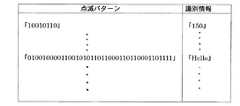
このようにして所定の規則に則した点滅を行う光源が見つかった場合、点滅情報変換部104は、変換辞書103をもとに、点滅パターンから識別情報に変換する(S302)。図3に変換辞書による記憶例を示すが、例えば点灯を1、消灯を0で表し、光源が0.1秒ごとに「10010110」という点滅パターンを持っていた場合には、「150」という数字を意味し、同様に「0100100001100101011011000110110001101111」という点滅パターンの場合には「Hello」という文字列を意味するなどである。
【0024】
このようにして変換された識別情報は、表示・記録用映像とともに、あるいは別々に関連情報出力部106に送られ、表示・記録用映像に多重化される(S303)。ここで、多重化とは映像に関連付けて復元できる形で格納することである。処理すべき映像が終わると終了し、処理すべき映像があると再度、S301の処理に戻る(S304)。
【0025】
図4をもとに、点滅パターンの検出と、識別情報と映像を多重化する例を説明する。ここでカメラで撮像した映像201の中には、点滅光源202が二箇所存在する。点滅パターンから識別情報を復号した結果、一方が「(T)Kendall Station, Cambridge 」という識別情報を、他方が「Food Court, Open Hours 8am-7pm」という識別情報を発信していることが分かったとする。どちらの光源がどちらの識別情報を発信しているかについては、ここでは特定しない。
【0026】
識別情報と映像の多重化の例として音声を用いる方法がある。つまり、映像201を動画として記録し、その音声トラックに識別情報203を音声として記録する方法である。その他の例としては、映像のディジタルファイル中に識別情報203を含める方法がある。例えばJPEG(Joint Photographic Coding Experts Group)をはじめとする静止画像、MPEG(Moving Picture Experts Group)をはじめとする動画像のディジタルデータ形式には、付加情報を記録するための領域を設けることができる。この付加情報領域に、識別情報を記録してもよい。また、映像は映像ファイルとして、識別情報はテキストファイルとして出力してもよい。このようにして識別情報を関連付けて出力された映像は、以下のように利用できる。
【0027】
例えば、観光地において史跡を撮影した写真中に、上に示した所定の規則に則した点滅をする光源があり、点滅によって史跡の解説を行っていれば、後日、その写真を閲覧すると、識別情報として記録されていた史跡の解説文を表示させたり、音声で聴いたりすることができる。識別情報としてインターネット上の情報アクセスの場所を示すURL(Uniform Resource Locator。インターネット上で情報源の所在地を示す英数字記号列)が用いられていた場合、撮影された写真をコンピュータ上で閲覧する際に、インターネット経由でより詳細な情報を得ることもできる。
【0028】
また、撮影した映像および識別情報は必ずしも記録・蓄積しなくてもよい。小型カメラを身につけて生活するウェアラブル・コンピュータ・システムの場合、店の看板が発する「今から15分間、牛乳30%引き」という識別情報をカメラが受信すると、そのことを表示や音声で利用者(装着者)に提示するという例も考えられる。
【0029】
以上のように関連情報出力部106から識別情報が多重化された映像データは出力され、記憶媒体(図示しない)に記録されたり、別の処理装置(図示しない)に送られたりする。
【0030】
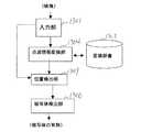
図5は本発明の映像情報処理装置の第2の実施例の構成を示す説明図である。図5における入力部401、変換辞書403、点滅情報変換部404、関連情報出力部406は、それぞれ図1の入力部101、変換辞書103、点滅情報変換部104、関連情報出力部106と同じである。本発明の第2の映像情報処理装置においては、本発明の第1の映像情報処理装置に加え位置検出部409を備えることを特徴とする。
【0031】
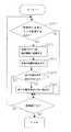
図6は、この手順を示したフローチャートである。入力部401より入力された映像は、表示・記録用と点滅検査用、そして点滅位置観測用に分けられる。これら3つの映像の内容は同一である。第1の実施例と同様に、点滅情報変換部404は映像中に所定の規則に則した点滅を行う光源があるかどうかを判定する(S601)。そして、変換辞書403をもとに、点滅パターンから識別情報に変換する(S602)。
【0032】
位置検出部409は、点滅情報変換部404が識別情報に変換した点滅パターンが、映像中のどの位置にある画素から発信されているかを計算し(S603)、点滅パターンから変換された識別情報と位置情報を関連情報出力部406に送る。関連情報出力部406では、第1の実施例と同様に映像に位置付きの識別情報を多重化して出力する(S604)。処理すべき映像が終わると終了し、処理すべき映像があると再度、S601の処理に戻る(S605)。
【0033】
なお、S603の映像中で点滅光源の位置を計算する方法の一例としては、本発明の第1の実施例に述べたように、オプティカルフローを利用したオブジェクト追跡手法が一般的であるが、本発明では位置計算の方法をこれに限定するものではない。
【0034】
図7では、このようにして位置を特定して上で識別情報が多重化記録された場合の活用例を示している。映像501内に2箇所の点滅光源502が存在しており、入口ドアの上に取り付けられた点滅光源は「Food Court, Open Hours 8am-7pm」というパターンで点滅しており、脇の壁面に取り付けられた光源は「Kendall Station, Cambridge」という点滅パターンを発している。
【0035】
ここでは、それぞれの点滅光源の位置情報を含んでいるので、それぞれの光源502に近い位置に「ふきだし」503として表示することができるようになっている。このような映像を利用する場合、第1の実施例に加えて以下のような効果がある。
【0036】
例えば、観光地において史跡を撮影した写真中に、上で示した所定の規則に則した点滅をする光源があり、点滅によって史跡各部(寺社、碑、植物など)の解説を行っていれば、後日、その写真を閲覧する際に興味ある被写体を指示すると、識別情報として記録されていた史跡各部の解説文を表示させたり、音声で聴いたりすることができる。識別情報としてインターネット上の情報アクセスの場所を示すURLが用いられていた場合、撮影された写真をコンピュータ上で閲覧する際に、被写体ごとにインターネット経由でより詳細な情報を得ることもできる(クリッカブル・イメージ)。
【0037】
また、撮影した映像および識別情報は必ずしも記録・蓄積しなくてもよい。小型カメラを身につけ、メガネ状のディスプレイを身につけて生活するウェアラブル・コンピュータ・システムの場合、カメラ視野にある店の看板が発する「今から15分間、牛乳30%引き」という識別情報をカメラが受信すると、ディスプレイ内においてどの店が牛乳の安売りをしているのかを直感的に理解できる方法で提示することができる。
【0038】
図8は本発明の映像情報処理装置の第3の実施例の構成を示す説明図である。図8における入力部701、変換辞書703、点滅情報変換部704は、それぞれ図1の入力部101、変換辞書103、点滅情報変換部104と同じであるが、関連情報出力部106に代わり映像加工部706を有する構成になっている。図9は本発明の第3の実施例を説明するためのフローチャートである。
【0039】
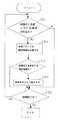
第1の実施例と同様に、入力部701から入力した映像に対し、点滅情報変換部404は映像中に所定の規則に則した点滅を行う光源があるかどうかを判定する(S901)。そして、変換辞書703をもとに、点滅パターンから識別情報に変換する(S902)。
【0040】
点滅情報変換部704から送られてくる識別情報が映像加工を要求するものであった場合(S903)、映像加工部706は映像加工を施して出力する(S904)。処理すべき映像が終わると終了し、処理すべき映像があると再度、S901の処理に戻る(S905)。
【0041】
図10では、このようにして位置を特定して上で識別情報が多重化記録された場合の活用例を示している。例えば映像801中の被写体803に「撮影禁止」という識別情報を発信するタグ802がある場合、映像加工部706は映像全面を黒く塗りつぶしたり、撮影禁止であることを示す文字や記号を映像中に書き加えたりして出力する。
【0042】
本発明の第2の映像情報処理装置のように、映像中でどのタグ(点滅光源)がどの識別情報を発信しているかを知る手段がある場合には、「私を撮影しないで」という識別情報を発信している被写体803だけについて、画面内で黒く塗りつぶしたり「ぼかし」や「モザイク」という加工(マスクされた被写体)を施した映像804を出力する。
【0043】
映像中では点のように見えるタグの位置から、それを身につけている人物の領域を計算する方法としては、例えば映像を細かいメッシュ状に分割し、映像各部の動きベクトル(現在の画面と次の画面で、メッシュ状の各部がどこに移動したかというベクトル)を計算した上で、背景と異なる動きベクトルを持っている部分を一つの被写体領域としてとらえる方法や、タグのある部分(被写体の体の一部など)から領域を拡張していき、色相ヒストグラムなどが大幅に変化する部分までを被写体とする方法などがある。これらの方法はオブジェクト切り出し技術と呼ばれ、様々な方法が提案されているが、本発明はどのオブジェクト切り出し技術を用いるかということには依存しない。
【0044】
また、オブジェクト切り出しを行わなくても、「タグの周辺・半径20ピクセル」などのように、規定の面積の領域を自動的に修正するという方法でもよい。さらに、被写体が発する識別情報は「撮影禁止」というものに限定されない。例えば、被写体が氏名やURLなどを発信している場合には、写真内でそのタグが映っている場所、またはそのタグを身につけている被写体の付近に、その名前やURLなどを書き込むという映像加工を映像加工部706でおこなってもよい。
【0045】
図11は、本発明の映像情報処理装置の第4の実施例の構成を示す図である。図11における入力部1001、変換辞書1003、点滅情報変換部1004は、それぞれ図1の入力部101、変換辞書103、点滅情報変換部104と同じであるが、関連情報出力部106に代わりメッセージ出力部1006を有する構成になっている。また、図12は本発明の第4の実施例の手順を示すフローチャートである。
【0046】
例えば、銀行のATM機、またはATM機が設置されている部屋に取り付けられたカメラが本発明の入力部1001であり、「SOS(救助要請)」信号を発する被写体がそのカメラの視野内に入ったとする。第1の実施例と同様に、入力部1001から入力した映像に対し、点滅情報変換部1004は映像中に所定の規則に則した点滅を行う光源があるかどうかを判定する(S1201)。そして、変換辞書1003をもとに、点滅パターンから識別情報に変換する(S1202)。
【0047】
点滅情報変換部1004から送られてくる識別情報がメッセージ出力を要求するものであった場合(S1203)、メッセージ出力部1006はメッセージを出力する(S1204)。処理すべき映像が終わると終了し、処理すべき映像があると再度、S1201の処理に戻る(S1205)。
【0048】
図13には、この例を示すための映像を示す。カメラが捕らえた映像1101には、ATM機の近くに立つ人物1102が映っているが、その後ろには人物1102に脅威を与えている強盗1104が存在している。なお、強盗1104がカメラの捕らえた映像範囲内にいる必要はない。
【0049】
人物1102は、自分が脅迫されていることを通報したいが、通報することによって自分に危害が加わることを避けるために、通報は強盗1104に気づかれずに行いたい。そこで、自分が身につけている点滅光源(タグ)1103からSOS信号を発信するように設定する。
【0050】
このSOS信号は赤外線LEDの点滅によるため、強盗1104は目視では気づかれない。したがって、強盗1104に気づかれずに救助要請の意思表示を行うことができる。
【0051】
光源1103が発するSOS信号は、識別信号として本発明の入力部1001に入力され、点滅情報変換部1004で復号されたSOS信号がメッセージ出力部1006に送られる。メッセージ出力部1006は、SOS信号を受信したことを受けて、救助機関にその旨を伝達する。救助機関への伝達方法は、電話、インターネット、専用の通報回線など、様々であり、いかなる方法でもよい。また、SOS信号のみではなく、撮影した映像を添えて救助機関に送信すれば、救助機関では現場の状況をより詳細に知ることができる。
【0052】
また、第2の実施例で説明したように、映像中のどの被写体がSOS信号を発しているかを感知する場合には、この映像と位置情報を添えてSOS信号を救助機関に送信することにより、救助の対象者を、脅威の対象(例えば強盗や痴漢)に知られることなく特定することができる。
【0053】
さらに、本発明の適用は緊急時に限定しない。ATM機の例でいうならば、体の不自由な人が、自分の体が不自由であることを示す識別情報を発信するタグを身につけている場合、ATM機の前に介助の必要なお客様が来たことを銀行のスタッフに通報することも可能になる。また、駅などの公共の場面では、体の不自由な人が改札機に差し掛かったときには自動的に最寄りの改札機を開放にしたり、駅員が介助に行くように通報することも可能である。本発明の特徴は、監視カメラがある環境においては、その監視カメラを本発明の映像情報処理装置に置きかえれば、新たに無線受信機を設置しなくても、発信された識別情報を受信することができることにある。
【0054】
図14は、本発明の映像情報処理方法または装置の第5の実施例の構成を示す図である。図14における入力部1301、変換辞書1303、点滅情報変換部1304、位置検出部1309は、それぞれ図5の入力部401、変換辞書403、点滅情報変換部404と同じであるが、関連情報出力部406に代わり被写体検出部1306を有する構成になっている。
【0055】
また、図15は本発明の第5の実施例の手順を示すフローチャートである。この映像情報処理装置においては、カメラが撮影する映像範囲内に存在することが予定されている光源が撮影視野内に存在しない場合にはそれを撮影者に通知する。
【0056】
第2の実施例と同様に、点滅情報変換部1304は映像中に所定の規則に則した点滅を行う光源があるかどうかを判定する(S1601)。そして、変換辞書1303をもとに、点滅パターンから識別情報に変換する(S1602)。
【0057】
位置検出部1309は、点滅情報変換部1304が識別情報に変換した点滅パターンが、映像中のどの位置にある画素から発信されているかを計算し(S1603)、点滅パターンから変換された識別情報と位置情報を被写体検出部部1306に送る。被写体検出部1306では、予め登録された識別情報が読み取れたか判断する(S1604)。
【0058】
S1604の処理で、登録された識別情報が読み取れなかった場合、被写体検出部は被写体がすべてフレーム内にいないことを出力する(S1605)。処理すべき映像が終わると終了し、処理すべき映像があると再度、S1601の処理に戻る(S1606)。
【0059】
例えば、本発明の映像情報処理機能を有するカメラを持って4人の友人とともに旅行するとする。友人4人が点滅光源である赤外線IDタグ(赤外線で固有の識別情報を発信する装置)を身につけて行動し、その4つのIDタグの番号が既知である場合、その4番号をカメラにあらかじめ記憶させておくものとする。以下、図16をもとに説明する。
【0060】
図16には被写体となるべき人物1402、1404、1406、1408が描かれている。各人物はそれぞれ赤外線IDタグ1403、1405、1407、1409を身につけている。被写体検出部1306は、被写体としてこの4つの番号を記憶している。
【0061】
ここで、写真を撮影しようとする際、撮影に先駆けて撮影視野内に4つのタグが映っているかどうかをチェックする。すなわち、撮影領域1401内の点滅情報を点滅情報変換部1304において復号した結果、図16では「1403」「1405」「1407」だけが受信されたことが分かる。この例では赤外線タグが映像中のどの位置にいるかは関知しなくてよいので、位置検出部1309は、復号された識別情報つまり上記3つの番号だけを識別情報として出力する。位置を利用した例は後述する。
【0062】
被写体検出部1306は、あらかじめ記憶されている4つの番号と比較し、撮影領域1401の中で3つの番号しか受信できなかったことを検出する。そこで、本発明の映像情報処理装置は、カメラのファインダー内の警告表示、または警告音や音声による警告メッセージ、あるいはバイブレーターなどを用いて、全員が撮影視野内にないことを撮影者に対して通知する。これにより、撮影者は同行した友人3人が必ず写真に映るようにすることが容易になる。
【0063】
上記の説明では、本発明の映像情報処理装置が映像範囲内に存在することが予想されている光源の有無だけを判断したが、撮影視野内に警告領域を設け、その警告領域に光源がある場合に同様の警告表示または音声を提示することもできる。図17では、外側の実線枠1501が撮影領域を示し、内側の点線枠1502と撮影領域との間を警告領域とした例である。
【0064】
例えば、この警告領域に光源が映っている場合には「その光源をもつ被写体は、撮影した際に画面から切れる恐れがある」旨を警告することができる。上記の方法を逆に利用すれば、同行した友人4人が撮影視野内にある場合にそれを伝える表示または音声提示を行い、(4人全員を写真におさめるという)目的に対する準備が整ったことを利用者に伝えることもできる。
【0065】
また、上記で説明した警告領域を領域B、それ以外の撮影視野の映像領域(点線枠1502の内側)を領域Aと表現する場合、領域Aから領域Bへと光源が移動した場合にその旨を利用者に警告することもでき、撮影視野外から領域Bに光源が入ってきた場合にその旨を利用者に通知することもできる。
【0066】
さらに、変形例として、所定数の光源が撮影視野内にあるかどうかを検査し、所定の識別情報を発する光源が撮影視野内にある場合に、自動的に写真撮影を行うことも可能である。
【0067】
また、逆に所定の光源が撮影視野内にあるかどうかを検査し、あらかじめ指定した識別情報を発する光源が撮影視野内にない場合に、自動的に写真撮影を行うことも可能である。登録された識別情報が撮影視野内にない場合に撮影を行いたい理由の例としては、写真撮影を嫌う人物が同行者のなかにある場合が上げられる。そのうち1人が写真撮影を嫌う場合、その人物が視野内にある場合には撮影を行わない。
【0068】
また、カメラ自身が位置、方向、撮影範囲を自発的に変えることができる駆動部分を持っているものとすると、所定の光源が撮影視野から外れている、または外れようとしている場合、光源が撮影視野に入るように駆動部分に命令を発し、予定光源が撮影視野に入るように調整する。
【0069】
例えば、第5の実施例で説明した友人3人と旅行に出かけ、セルフタイマーを用いて総勢5人の写真を取ろうとするものとする。この際、カメラは所定の光源(この場合4人が所持する4つの光源)が撮影視野内にない場合には、望遠をテレ(遠景)側に調整して、より広い範囲が撮影範囲に入るように修正したり、撮影方向を上下左右に駆動したりして、4光源のすべてが撮影視野内にあるようにする。これにより、セルフタイマーを用いた写真撮影でも、失敗無く撮影を行うことができる。
【0070】
このような光学系の自動調整は、レンズの位置や方向を物理的に変えることで実現してもいいし、装置ではあらかじめ大きな映像範囲を撮影候補範囲として保持しており、撮影を行う際に、予定光源が含まれるように撮影対象範囲を選択してもよい。このような撮影視野調整が完了した際に、撮影を行うように利用者に促してもよいし、装置が自動的に撮影を行ってもよい。
【0071】
また逆に、所定の光源が撮影範囲に含まれないようにカメラを調整することも可能である。
【0072】
図18は、点滅光源となる発信装置の構成例を示した図である。この発信装置は、識別情報に対応する点滅パターンを記憶した点滅パターン記憶部180と、点滅パターン記憶部に記憶されたパターンでを発光させるタイミングを生成するためのタイミング生成部182と、このタイミング生成部で生成されたタイミングをもとに、上記点滅パターンで発光する発光部184とを有する。
【0073】
ここで、発信装置の形態は特に問わない。例えば、店や史跡の案内看板に取り付けてもよいし、人物に取り付けられるようにバッチのような形態でもよい。
【0074】
また、本願発明の映像情報処理装置の実施例における処理をコンピュータで実行可能なプログラムで実現し、このプログラムをコンピュータで読み取り可能な記憶媒体として実現することも可能である。
【0075】
なお、本願発明における記憶媒体としては、磁気ディスク、フロッピーディスク、ハードディスク、光ディスク(CD−ROM,CD−R,DVD等)、光磁気ディスク(MO等)、半導体メモリ等、プログラムを記憶でき、かつコンピュータが読み取り可能な記憶媒体であれば、その記憶形式は何れの形態であってもよい。
【0076】
また、記憶媒体からコンピュータにインストールされたプログラムの指示に基づきコンピュータ上で稼動しているOS(オペレーションシステム)や、データベース管理ソフト、ネットワーク等のMW(ミドルウェア)等が本実施形態を実現するための各処理の一部を実行してもよい。
【0077】
さらに、本願発明における記憶媒体は、コンピュータと独立した媒体に限らず、LANやインターネット等により伝送されたプログラムをダウンロードして記憶または一時記憶した記憶媒体も含まれる。
【0078】
また、記憶媒体は1つに限らず、複数の媒体から本実施形態における処理が実行される場合も、本発明における記憶媒体に含まれ、媒体の構成は何れの構成であってもよい。
【0079】
なお、本願発明におけるコンピュータは、記憶媒体に記憶されたプログラムに基づき、本実施形態における各処理を実行するものであって、パソコン等の1つからなる装置、複数の装置がネットワーク接続されたシステム等の何れの構成であってもよい。
【0080】
また、本願発明におけるコンピュータとは、パソコンに限らず、情報処理機器に含まれる演算処理装置、マイコン等も含み、プログラムによって本願発明の機能を実現することが可能な機器、装置を総称している。
【0081】
尚、本発明の映像情報処理装置または発信装置は、上述の実施例にのみ限定されるものではなく、本発明の要旨を逸脱しない範囲内において種々変更を加え得ることは勿論である。
【0082】
【発明の効果】
以上、説明したように本発明の映像情報処理方法または装置によれば、タグが発信する識別情報を映像処理によって読み取り、映像を様々に作用させることができるという優れた効果を奏し得る。
【図面の簡単な説明】
【図1】本発明の一実施例である映像情報処理装置の構成を示す図である。
【図2】本発明の一実施例である映像情報処理装置の動作の流れを示すフローチャートを示す図である。
【図3】本発明の一実施例である映像情報処理装置の変換辞書の一例を示す図である。
【図4】本発明の一実施例である映像情報処理装置の出力情報の一例を示す図である。
【図5】本発明の一実施例である映像情報処理装置の構成を示す図である。
【図6】本発明の一実施例である映像情報処理装置の動作の流れを示すフローチャートを示す図である。
【図7】本発明の一実施例である映像情報処理装置の出力情報の一例を示す図である。
【図8】本発明の一実施例である映像情報処理装置の構成を示す図である。
【図9】本発明の一実施例である映像情報処理装置の動作の流れを示すフローチャートを示す図である。
【図10】本発明の一実施例である映像情報処理装置の出力情報の一例を示す図である。
【図11】本発明の一実施例である映像情報処理装置の構成を示す図である。
【図12】本発明の一実施例である映像情報処理装置の動作の流れを示すフローチャートを示す図である。
【図13】本発明の一実施例である映像情報処理装置の出力情報の一例を示す図である。
【図14】本発明の一実施例である映像情報処理装置の構成を示す図である。
【図15】本発明の一実施例である映像情報処理装置の動作の流れを示すフローチャートを示す図である。
【図16】本発明の一実施例である映像情報処理装置の出力情報の一例を示す図である。
【図17】本発明の一実施例である映像情報処理装置の処理動作を制御する領域設定を説明する図である。
【図18】本発明の一実施例である発信装置の構成を示す図である。
【符号の説明】
101、401、701、1001、1301…入力部
103、403、703、1003、1303…変換辞書
104、404、1004、1304…点滅情報変換部
106、406…関連情報出力部
201、501、801、1101、1401…撮影領域
202、502、802、1103…点滅光源
203、503…識別情報
409、1309…位置検出部
706…映像加工部
803、1402、1404、1406、1408…被写体
804…処理後の映像
805…マスクされた被写体
1006…メッセージ出力部
1102…脅迫されている人物
1104…脅迫している人物
1306…被写体検出部
1403、1405、1409…赤外線タグ(点滅光源)
180…点滅パターン記憶部
182…タイミング生成部
184…発光部[0001]
BACKGROUND OF THE INVENTION
The present invention relates to a video information processing apparatus that processes video based on subject identification information.
[0002]
[Prior art]
Conventionally, wireless information transmission / reception methods using infrared and gigahertz frequency bands have been generally used, and are widely applied to televisions, video decks, wireless LANs, and the like. Also, a short-range wireless standard called Bluetooth is being made.
[0003]
On the other hand, a digital camera that records video data captured by a solid-state imaging device such as a CCD in an electronic memory element instead of recording a video by a chemical reaction on photographic paper is also widely used.
[0004]
[Problems to be solved by the invention]
However, when taking a picture as a business or hobby, the larger the number of shots, the more time is required for organizing later, and after that, in order to confirm the contents of the picture, the picture itself must be browsed. There is a problem that cannot be judged. On the other hand, when there are a plurality of objects of interest in one image, a method of adding annotations to each of them has been proposed (Japanese Patent Laid-Open No. 6-343146), but this work also takes some time.
[0005]
Also, with conventional surveillance cameras, humans watch the camera image visually to determine the necessity of rescue, and it is impossible to request rescue from the subject side voluntarily and without being known by others. As a result, victims who were threatened to do harm if reported would not be able to report without being known to the perpetrator, even in front of the surveillance camera.
[0006]
Furthermore, a user who is not accustomed to taking a picture with a camera may find it difficult to keep a plurality of subjects within the shooting range. Further, when taking a picture, there may be a subject that does not like to be photographed among subjects unrelated to the photography, which is a problem related to privacy.
[0007]
In view of such circumstances, the present invention realizes a camera that can easily realize the above-described video organization, and realizes a camera that multiplexes and records information that describes the video, To realize a camera that has a function of transmitting the intention of a subject without being known to surrounding people, and to realize a camera that can easily confirm that a desired subject is surely within the shooting range. And
[0008]
[Means for Solving the Problems]
In the present invention, the input means for inputting video, the storage means for storing identification information corresponding to the blinking pattern by the blinking light source, and the input based on the identification information stored in the storage means The blinking information conversion means for converting into the identification information corresponding to the blinking pattern of the light source blinking in the video inputted by the means, and the identification information converted by the blinking information conversion means are output together with the inputted video And an output means for performing the above.
[0009]
When the identification information is a URL, a “clickable image” that can display an Internet page corresponding to the subject by clicking on the subject in the photo on the computer screen at a later date is automatically created. It can be created, and the trouble of adding information to the video separately from shooting is omitted.
[0010]
Also, input means for inputting video, storage means for storing identification information corresponding to the blinking pattern by the blinking light source, and input by the input means based on the identification information stored in the storage means Blinking information conversion means for converting into blinking information of the light source blinking in the recorded video, and identification information converted by the blinking information conversion means for outputting together with the inputted video Output means.
[0011]
As a result, if the identification information issued by the subject is “I do not like photography”, a part or all of the screen is corrected. This protects the privacy of subjects who do not like taking pictures. Shooting is allowed, but it is also possible to use the video information processing apparatus of the present invention to send a picture of yourself to be sent at a later date, or to charge for the fact that you have shown yourself.
[0012]
Further, input means for inputting video, storage means for storing identification information corresponding to the blinking pattern by the blinking light source, and input by the input means based on the identification information stored in the storage means A blinking information conversion means for converting to the blinking pattern of the light source blinking in the displayed video, and a preset message is output according to the identification information converted by the blinking information conversion means Message output means.
[0013]
As a result, when a subject that emits identification information meaning “SOS” is within the shooting range, a rescue organization or police is automatically notified. As a result, if a security camera installed in a bank ATM (convenience store), convenience store, city area, etc. reads SOS (rescue request) identification information, the source of the threat (such as a burglar or molester) It is possible to automatically report to a rescue organization without being detected by.
[0014]
Further, input means for inputting video, storage means for storing identification information corresponding to the blinking pattern by the blinking light source, and input by the input means based on the identification information stored in the storage means Blinking information conversion means for converting into identification information corresponding to a blinking pattern of a light source that blinks in the recorded image, position detection means for detecting the position of the blinking light source in the image, and a subject to be detected Subject storage means for storing identification information indicating the position of the subject having the identification information stored in the subject storage means, the identification information converted by the blink information conversion means Subject detection means for detecting based on the position of the blinking light source detected by the above.
[0015]
As a result, if identification information generated by a subject to be photographed (not desired) is registered in the video information processing apparatus of the present invention in advance, the camera can determine whether or not the subject to be photographed (desired) is within the photographing range. Is detected and is not within the shooting range (enters), this is notified to the photographer. Or, when the subject to be photographed (not desired) enters the photographing range (when it comes out), the photographing is automatically performed. As a result, even when a photographer unfamiliar with taking a picture takes a picture, it is possible to easily take a picture in which the target subject is correctly placed in the frame.
[0016]
Further, it is a transmitting device for transmitting identification information for each subject to a video processing device that processes an image based on the identification information of the subject, and is a flashing device that stores a flashing pattern indicating the identification information of the subject. It has a pattern storage means and a light emission means for emitting the blinking pattern stored in the blinking pattern storage means at a predetermined timing. With this transmitter, identification information can be transmitted to the video processing apparatus.
[0017]
DETAILED DESCRIPTION OF THE INVENTION
Hereinafter, embodiments of the present invention will be described with reference to the drawings. The video information processing apparatus of the present invention will be described with reference to the drawings. In the following description, the term “camera” may be used for convenience. However, the form of the video information processing apparatus of the present invention is not necessarily limited to the one integrated with the photo camera. For example, a camera is connected to a personal computer, and calculation processing such as reading of identification information may be performed on the personal computer side, or the camera has a function of transmitting captured images to a remote place by wireless or wired communication. It may be carried out and a calculation process such as reading of identification information may be performed by a personal computer or the like that has received the video.
[0018]
FIG. 1 is a diagram showing the configuration of the first embodiment of the present invention. Video information is input from an
[0019]
The processing video is sent to the blink
[0020]
The predetermined rule is, for example, an infrared remote controller for remotely controlling home appliances such as a television receiver, a video tape player, or an air conditioner, a notebook personal computer, or a notebook personal computer and a printer. An IrDA (Infrared Data Association) protocol for wirelessly exchanging information may be used, or other rules may be used.
[0021]
Here, the method for identifying the presence or absence of blinking is not limited, but the simplest example of finding blinking is to add up the luminance of all the pixels included in the video and observe the change in the total value over several frames. There is a way to do it. For example, if the total luminance value of all the pixels in three frames is 39321600 from a certain point in time, the total luminance value of the next three frames is 39322112, and the total luminance value of the next three frames returns to 39321600. If the camera angle does not change and there is no moving object on the screen without zooming (for example, a surveillance camera in an unattended area), it is assumed that some pixels of the screen are blinking.
[0022]
As another recognition example, a window (part of the screen) for searching for a blinking pixel may be limited, and blinking may be determined in the area in the same manner as the above-described technique. Further, when the blinking pixel is moving in the screen, the area itself may be made to follow the movement of the blinking object. As a follow-up method in this case, it is common to use a partial matching method between the previous and next video frames using an optical flow.
[0023]
When a light source that blinks in accordance with a predetermined rule is found in this way, the blink
[0024]
The identification information thus converted is sent to the related
[0025]
Based on FIG. 4, an example of detecting a blinking pattern and multiplexing identification information and video will be described. Here, two blinking
[0026]
As an example of multiplexing of identification information and video, there is a method using audio. That is, the
[0027]
For example, if there is a light source that blinks in accordance with the predetermined rules shown above in a photograph taken of a historical site at a tourist spot, and the historical site is explained by blinking, it will be identified by browsing the photo at a later date. It is possible to display explanations of historical sites recorded as information and listen to them by voice. When a URL (Uniform Resource Locator; an alphanumeric symbol string indicating the location of an information source on the Internet) indicating the location of information access on the Internet is used as identification information, when viewing a photograph taken on a computer In addition, more detailed information can be obtained via the Internet.
[0028]
The captured video and identification information need not necessarily be recorded / stored. In the case of a wearable computer system that wears a small camera, when the camera receives the identification information “30% milk discount for 15 minutes from now” issued by the signboard of the store, it is displayed and voiced to the user An example of presenting to (wearer) is also conceivable.
[0029]
As described above, the video data on which the identification information is multiplexed is output from the related
[0030]
FIG. 5 is an explanatory diagram showing the configuration of the second embodiment of the video information processing apparatus of the present invention. The
[0031]
FIG. 6 is a flowchart showing this procedure. The video input from the
[0032]
The
[0033]
As an example of the method for calculating the position of the blinking light source in the image in S603, as described in the first embodiment of the present invention, an object tracking method using an optical flow is generally used. In the invention, the position calculation method is not limited to this.
[0034]
FIG. 7 shows an example of utilization when the position is specified in this way and the identification information is multiplexed and recorded. There are two flashing
[0035]
Here, since the position information of each blinking light source is included, it can be displayed as a “speech balloon” 503 at a position close to each
[0036]
For example, if there is a light source that blinks in accordance with the predetermined rules shown above in a photograph of a historical site taken at a tourist spot, and the historical site parts (temples, monuments, plants, etc.) are explained by flashing, At a later date, if an object of interest is pointed out when viewing the photograph, the explanation text of each part of the historic site recorded as identification information can be displayed or listened to by voice. When a URL indicating the location of information access on the Internet is used as identification information, more detailed information can be obtained via the Internet for each subject when browsing a photographed picture on a computer (clickable) ·image).
[0037]
The captured video and identification information need not necessarily be recorded / stored. In the case of a wearable computer system that wears a small camera and wears a glasses-like display, the camera displays the identification information “15% milk discount for 15 minutes from now” issued by the signboard of the store in the camera field of view. When received, it can be presented in a manner that allows intuitive understanding of which store is selling milk in the display.
[0038]
FIG. 8 is an explanatory diagram showing the configuration of the third embodiment of the video information processing apparatus of the present invention. The
[0039]
As in the first embodiment, for the video input from the
[0040]
When the identification information sent from the blinking
[0041]
FIG. 10 shows a utilization example when the position is specified in this way and the identification information is multiplexed and recorded. For example, when the subject 803 in the
[0042]
When there is a means for knowing which identification information is transmitted by which tag (flashing light source) in the video as in the second video information processing apparatus of the present invention, the identification "Do not shoot me" For only the subject 803 that is transmitting information, an
[0043]
As a method of calculating the region of a person wearing a tag from the position of a tag that looks like a dot in the video, for example, the video is divided into fine meshes, and the motion vectors of each part of the video (current screen and next In this screen, calculate the mesh where each part of the mesh moved), and then capture the part with the motion vector different from the background as one subject area, or the part with the tag (subject body There is a method in which the area is expanded from a part of the subject, etc., and the part up to the part where the hue histogram etc. changes significantly is used. These methods are called object cutout techniques, and various methods have been proposed, but the present invention does not depend on which object cutout technique is used.
[0044]
In addition, a method of automatically correcting a region having a specified area such as “periphery of tag / radius of 20 pixels” without cutting out the object may be used. Furthermore, the identification information emitted by the subject is not limited to “shooting prohibited”. For example, if the subject is sending a name, URL, etc., a video of writing the name, URL, etc. in the place where the tag appears in the photo or near the subject wearing the tag Processing may be performed by the video processing unit 706.
[0045]
FIG. 11 is a diagram showing the configuration of the fourth embodiment of the video information processing apparatus of the present invention. The
[0046]
For example, a bank ATM machine or a camera attached to a room where the ATM machine is installed is the
[0047]
When the identification information sent from the blinking
[0048]
FIG. 13 shows an image for showing this example. The image 1101 captured by the camera shows a person 1102 standing near the ATM machine, and behind that is a burglar 1104 that poses a threat to the person 1102. It is not necessary for the robber 1104 to be within the video range captured by the camera.
[0049]
The person 1102 wants to report that he / she is threatened, but wants to report without being noticed by the robber 1104 in order to avoid harming himself / herself by reporting. Accordingly, the SOS signal is set to be transmitted from the blinking light source (tag) 1103 worn by the user.
[0050]
Since this SOS signal is due to blinking of the infrared LED, the burglar 1104 is not noticed visually. Therefore, the intention to rescue can be displayed without the robber 1104 noticing.
[0051]
The SOS signal emitted from the light source 1103 is input to the
[0052]
In addition, as described in the second embodiment, when sensing which subject in the video emits the SOS signal, the SOS signal is transmitted to the rescue organization with the video and the position information. The person to be rescued can be identified without being known by the threat target (for example, a robber or a molester).
[0053]
Furthermore, the application of the present invention is not limited to an emergency. In the case of an ATM machine, if a handicapped person wears a tag that transmits identification information indicating that his / her body is handicapped, assistance is required before the ATM machine. It is also possible to notify the bank staff that the customer has come. In public places such as stations, when a handicapped person approaches the ticket gate, it is possible to automatically open the nearest ticket gate or to notify the station staff to go for assistance. A feature of the present invention is that, in an environment where there is a surveillance camera, if the surveillance camera is replaced with the video information processing apparatus of the present invention, the transmitted identification information can be received without newly installing a wireless receiver. There is in being able to.
[0054]
FIG. 14 is a diagram showing the configuration of a fifth embodiment of the video information processing method or apparatus according to the present invention. The
[0055]
FIG. 15 is a flowchart showing the procedure of the fifth embodiment of the present invention. In this video information processing apparatus, when a light source scheduled to exist within the video range captured by the camera does not exist within the shooting field of view, this is notified to the photographer.
[0056]
As in the second embodiment, the blink
[0057]
The
[0058]
If the registered identification information cannot be read in the process of S1604, the subject detection unit outputs that all the subjects are not in the frame (S1605). When the video to be processed ends, the process ends. When there is a video to be processed, the process returns to S1601 again (S1606).
[0059]
For example, it is assumed that the user travels with four friends with the camera having the video information processing function of the present invention. When four friends act by wearing infrared ID tags (devices that transmit unique identification information by infrared rays) as flashing light sources, and the numbers of the four ID tags are known, the four numbers are assigned to the camera in advance. It shall be remembered. Hereinafter, a description will be given with reference to FIG.
[0060]
FIG. 16 shows
[0061]
Here, when attempting to take a picture, it is checked whether or not four tags are reflected in the field of view prior to photography. That is, as a result of decoding the blinking information in the
[0062]
The
[0063]
In the above description, the video information processing apparatus of the present invention has determined only the presence or absence of a light source that is expected to exist within the video range. However, a warning area is provided in the shooting field of view, and there is a light source in the warning area. In some cases, a similar warning display or sound can be presented. FIG. 17 shows an example in which the outer
[0064]
For example, when a light source is reflected in this warning area, it can be warned that “the subject having the light source may be disconnected from the screen when photographed”. If you use the above method in reverse, you will be prepared for the purpose (to put all four of them in a photo) with a display or audio presentation that tells you when your four friends are in the field of view. Can be communicated to the user.
[0065]
In addition, when the warning area described above is expressed as area B, and the video area of the other field of view (inside the dotted frame 1502) is expressed as area A, when the light source moves from area A to area B, that fact Can be warned, and when the light source enters the area B from outside the field of view, it can be notified to the user.
[0066]
Further, as a modified example, it is possible to inspect whether or not a predetermined number of light sources are in the photographing field of view, and when a light source that emits predetermined identification information is in the photographing field of view, it is possible to automatically take a picture. .
[0067]
Conversely, it is possible to inspect whether or not a predetermined light source is in the photographing field of view, and when a light source that emits pre-specified identification information is not in the photographing field of view, it is possible to automatically take a picture. As an example of the reason for wanting to take a picture when the registered identification information is not within the photographing field of view, there is a case where a person who hates taking a picture is among the accompanying persons. If one of them dislikes taking a picture and the person is in the field of view, no picture is taken.
[0068]
Assuming that the camera itself has a drive part that can change its position, direction, and shooting range spontaneously, if the specified light source is out of or out of the shooting field of view, the light source will shoot. A command is issued to the drive part so as to enter the field of view, and the planned light source is adjusted to enter the field of view.
[0069]
For example, it is assumed that a trip with three friends described in the fifth embodiment is taken and a total of five photographs are taken using a self-timer. At this time, if the camera does not have a predetermined light source (four light sources possessed by four people in this case) within the field of view, the camera adjusts the telephoto side to the tele (far view) side so that a wider range falls within the shooting range. In such a manner, all the four light sources are in the photographing field of view by correcting them in such a manner as to drive the photographing direction vertically and horizontally. As a result, even when taking a picture using a self-timer, the picture can be taken without failure.
[0070]
Such automatic adjustment of the optical system may be realized by physically changing the position and direction of the lens, and the apparatus holds a large video range as a shooting candidate range in advance. The photographing target range may be selected so that the planned light source is included. When such shooting field adjustment is completed, the user may be prompted to perform shooting, or the apparatus may automatically perform shooting.
[0071]
Conversely, it is also possible to adjust the camera so that a predetermined light source is not included in the shooting range.
[0072]
FIG. 18 is a diagram illustrating a configuration example of a transmission device serving as a blinking light source. The transmission device includes a blinking
[0073]
Here, the form of the transmission device is not particularly limited. For example, it may be attached to a signboard of a store or a historical site, or may be in a batch form so as to be attached to a person.
[0074]
Further, the processing in the embodiment of the video information processing apparatus of the present invention can be realized by a computer-executable program, and this program can be realized as a computer-readable storage medium.
[0075]
The storage medium in the present invention can store programs such as a magnetic disk, floppy disk, hard disk, optical disk (CD-ROM, CD-R, DVD, etc.), magneto-optical disk (MO, etc.), semiconductor memory, etc. As long as it is a computer-readable storage medium, the storage format may be any form.
[0076]
Further, an OS (operation system) operating on the computer based on an instruction of a program installed in the computer from the storage medium, database management software, MW (middleware) such as a network, and the like for realizing the present embodiment A part of each process may be executed.
[0077]
Furthermore, the storage medium in the present invention is not limited to a medium independent of a computer, but also includes a storage medium in which a program transmitted via a LAN or the Internet is downloaded and stored or temporarily stored.
[0078]
Further, the number of storage media is not limited to one, and the processing in the present embodiment is executed from a plurality of media, and the configuration of the media may be any configuration included in the storage media in the present invention.
[0079]
The computer according to the present invention executes each process according to the present embodiment based on a program stored in a storage medium. The computer includes a single device such as a personal computer, and a system in which a plurality of devices are connected to a network. Any configuration may be used.
[0080]
The computer in the present invention is not limited to a personal computer, but includes a processing unit, a microcomputer, and the like included in an information processing device, and is a generic term for devices and devices capable of realizing the functions of the present invention by a program. .
[0081]
Note that the video information processing apparatus or transmission apparatus of the present invention is not limited to the above-described embodiment, and various modifications can be made without departing from the scope of the present invention.
[0082]
【The invention's effect】
As described above, according to the video information processing method or apparatus of the present invention, the identification information transmitted by the tag can be read by video processing, and an excellent effect can be achieved in that the video can be applied in various ways.
[Brief description of the drawings]
FIG. 1 is a diagram illustrating a configuration of a video information processing apparatus according to an embodiment of the present invention.
FIG. 2 is a flowchart illustrating an operation flow of the video information processing apparatus according to the embodiment of the present invention.
FIG. 3 is a diagram showing an example of a conversion dictionary of the video information processing apparatus according to the embodiment of the present invention.
FIG. 4 is a diagram illustrating an example of output information of a video information processing apparatus according to an embodiment of the present invention.
FIG. 5 is a diagram illustrating a configuration of a video information processing apparatus according to an embodiment of the present invention.
FIG. 6 is a flowchart showing an operation flow of the video information processing apparatus according to the embodiment of the present invention.
FIG. 7 is a diagram illustrating an example of output information of a video information processing apparatus according to an embodiment of the present invention.
FIG. 8 is a diagram illustrating a configuration of a video information processing apparatus according to an embodiment of the present invention.
FIG. 9 is a flowchart illustrating an operation flow of the video information processing apparatus according to the embodiment of the present invention.
FIG. 10 is a diagram illustrating an example of output information of a video information processing apparatus according to an embodiment of the present invention.
FIG. 11 is a diagram illustrating a configuration of a video information processing apparatus according to an embodiment of the present invention.
FIG. 12 is a flowchart showing an operation flow of the video information processing apparatus according to the embodiment of the present invention.
FIG. 13 is a diagram illustrating an example of output information of a video information processing apparatus according to an embodiment of the present invention.
FIG. 14 is a diagram illustrating a configuration of a video information processing apparatus according to an embodiment of the present invention.
FIG. 15 is a flowchart showing an operation flow of the video information processing apparatus according to the embodiment of the present invention.
FIG. 16 is a diagram illustrating an example of output information of a video information processing apparatus according to an embodiment of the present invention.
FIG. 17 is a diagram for explaining region setting for controlling the processing operation of the video information processing apparatus according to the embodiment of the present invention;
FIG. 18 is a diagram illustrating a configuration of a transmission device according to an embodiment of the present invention.
[Explanation of symbols]
101, 401, 701, 1001, 1301, ... input unit
103, 403, 703, 1003, 1303 ... Conversion dictionary
104, 404, 1004, 1304 ... blinking information conversion unit
106, 406 ... related information output unit
201, 501, 801, 1101, 1401,...
202, 502, 802, 1103 ... blinking light source
203, 503 ... identification information
409, 1309 ... position detector
706 ... Video processing department
803, 1402, 1404, 1406, 1408 ... Subject
804 ... Video after processing
805 ... Masked subject
1006 ... Message output part
1102 ... A threatened person
1104 ... A threatening person
1306: Subject detection unit
1403, 1405, 1409 ... infrared tag (flashing light source)
180... Flashing pattern storage unit
182: Timing generator
184 ... Light emitting part
Claims (4)
Translated fromJapanese点滅光源による点滅パターンに対応する識別情報を記憶する記憶部と、
前記記憶部に記憶された識別情報をもとに、前記入力部によって入力された映像内で点滅する光源の点滅パターンに対応する識別情報に変換する点滅情報変換部と、
入力された前記映像内での点滅光源の位置を検出する位置検出部と、
入力された前記映像を符号化して符号化データを生成する画像符号化部と、
前記点滅情報変換部によって変換された識別情報、および、前記位置検出部によって検出された点滅光源の位置を用いて、クリッカブル・イメージにおける指示領域および当該指示領域に対応付けられた識別情報を含むクリッカブル・イメージのデータを求め、前記クリッカブル・イメージのデータを前記符号化データに多重化して出力する出力部と、
を備える映像情報処理装置。An inputunit for inputting video;
A storageunit for storing identification information corresponding to a blinking pattern by a blinking light source;
Based on the identification information stored inthe storageunit, the blinking information convertingunit for converting the identification information corresponding to the blinking pattern of the light source to blink in the image input by the inputunit,
A positiondetector for detecting the position of the flashing light source withinthe inputted image,
An image encoding unit that encodes the input video to generate encoded data;
Using the identification information converted by the blinking information conversionunitand the position of the blinking light source detected by the position detectionunit, a clickable including an indication area in the clickable image and identification information associated with the indication area An outputunit forobtaining image data, multiplexing the clickable image data with the encoded data, and outputting themultiplexed data;
A video information processing apparatus.
ことを特徴とする請求項1に記載の映像情報処理装置The video information processing apparatus according to claim 1,
ことを特徴とする請求項1または請求項2に記載の映像情報処理装置The video information processing apparatus according to claim 1 or 2,
前記位置検出部によって検出された点滅光源の位置を用いて求められた、前記クリッカブル・イメージの閲覧者が指示すべき位置または領域の情報と、 Information on the position or area to be instructed by the viewer of the clickable image, obtained using the position of the blinking light source detected by the position detection unit;
前記閲覧者が前記指示すべき位置を指示した場合に提示される情報である、前記点滅情報変換部によって変換された識別情報を含む、 Including identification information converted by the blinking information conversion unit, which is information presented when the viewer indicates the position to be indicated,
ことを特徴とする請求項1から請求項3までのいずれか一項に記載の映像情報処理装置The video information processing apparatus according to any one of claims 1 to 3, wherein
Priority Applications (3)
| Application Number | Priority Date | Filing Date | Title |
|---|---|---|---|
| JP2000139253AJP3678404B2 (en) | 2000-05-12 | 2000-05-12 | Video information processing device |
| US09/852,086US6853750B2 (en) | 2000-05-12 | 2001-05-10 | Video information processing apparatus and transmitter for transmitting information to the same |
| US10/909,341US6993188B2 (en) | 2000-05-12 | 2004-08-03 | Video information processing apparatus and transmitter for transmitting information to the same |
Applications Claiming Priority (1)
| Application Number | Priority Date | Filing Date | Title |
|---|---|---|---|
| JP2000139253AJP3678404B2 (en) | 2000-05-12 | 2000-05-12 | Video information processing device |
Publications (2)
| Publication Number | Publication Date |
|---|---|
| JP2001320702A JP2001320702A (en) | 2001-11-16 |
| JP3678404B2true JP3678404B2 (en) | 2005-08-03 |
Family
ID=18646735
Family Applications (1)
| Application Number | Title | Priority Date | Filing Date |
|---|---|---|---|
| JP2000139253AExpired - Fee RelatedJP3678404B2 (en) | 2000-05-12 | 2000-05-12 | Video information processing device |
Country Status (2)
| Country | Link |
|---|---|
| US (2) | US6853750B2 (en) |
| JP (1) | JP3678404B2 (en) |
Families Citing this family (60)
| Publication number | Priority date | Publication date | Assignee | Title |
|---|---|---|---|---|
| US8224078B2 (en) | 2000-11-06 | 2012-07-17 | Nant Holdings Ip, Llc | Image capture and identification system and process |
| US7565008B2 (en) | 2000-11-06 | 2009-07-21 | Evryx Technologies, Inc. | Data capture and identification system and process |
| US7899243B2 (en) | 2000-11-06 | 2011-03-01 | Evryx Technologies, Inc. | Image capture and identification system and process |
| US9310892B2 (en) | 2000-11-06 | 2016-04-12 | Nant Holdings Ip, Llc | Object information derived from object images |
| US7680324B2 (en) | 2000-11-06 | 2010-03-16 | Evryx Technologies, Inc. | Use of image-derived information as search criteria for internet and other search engines |
| AU2003302450A1 (en)* | 2002-11-25 | 2004-06-18 | Nippon Telegraph And Telephone Corporation | Real world object recognition method and device, and attached device |
| JP4058352B2 (en)* | 2003-01-07 | 2008-03-05 | キヤノン株式会社 | Imaging apparatus and imaging control method |
| TW200500965A (en)* | 2003-06-17 | 2005-01-01 | Sin Etke Technology Co Ltd | Personal carry-on rescue system |
| JP4345424B2 (en)* | 2003-10-01 | 2009-10-14 | 株式会社ニコン | Camera system |
| KR20060131780A (en) | 2003-11-19 | 2006-12-20 | 마츠시타 덴끼 산교 가부시키가이샤 | Digital camera system with means for limiting image acquisition |
| JP4509619B2 (en)* | 2004-03-24 | 2010-07-21 | 株式会社日立製作所 | Video processing device operation program |
| US8077980B2 (en) | 2004-05-18 | 2011-12-13 | Panasonic Corporation | Image processing apparatus |
| CN100555914C (en)* | 2004-05-31 | 2009-10-28 | 卡西欧计算机株式会社 | Information receiving apparatus, information transmission system, and information receiving method |
| KR100585604B1 (en)* | 2004-08-26 | 2006-06-07 | 삼성테크윈 주식회사 | Control method of digital photographing apparatus and digital photographing apparatus employing this method |
| US7004387B1 (en)* | 2004-10-15 | 2006-02-28 | Kaimikaua Charles M | System and method for preventing theft at automatic teller machines |
| JP5002131B2 (en)* | 2005-04-05 | 2012-08-15 | キヤノン株式会社 | Imaging device for monitoring and control method thereof |
| EP1886486A4 (en)* | 2005-05-16 | 2010-10-13 | Human Monitoring Ltd | Monitoring method and device |
| JP5032798B2 (en)* | 2006-03-24 | 2012-09-26 | 富士フイルム株式会社 | Information providing apparatus, information providing system, and information providing method |
| JP4855130B2 (en)* | 2006-04-27 | 2012-01-18 | 京セラ株式会社 | Information processing apparatus and data recording / storing method |
| JP5106903B2 (en)* | 2007-03-30 | 2012-12-26 | 株式会社東芝 | Mobile monitoring system |
| JP5397030B2 (en)* | 2009-06-15 | 2014-01-22 | カシオ計算機株式会社 | Movie recording apparatus and program |
| US8502856B2 (en) | 2010-04-07 | 2013-08-06 | Apple Inc. | In conference display adjustments |
| WO2011154949A2 (en)* | 2010-06-10 | 2011-12-15 | Audhumbla Ltd. | Optical tracking system and method for herd management therewith |
| US10185841B2 (en) | 2013-10-10 | 2019-01-22 | Elwha Llc | Devices, methods, and systems for managing representations of entities through use of privacy beacons |
| US10102543B2 (en)* | 2013-10-10 | 2018-10-16 | Elwha Llc | Methods, systems, and devices for handling inserted data into captured images |
| US10013564B2 (en) | 2013-10-10 | 2018-07-03 | Elwha Llc | Methods, systems, and devices for handling image capture devices and captured images |
| US10346624B2 (en) | 2013-10-10 | 2019-07-09 | Elwha Llc | Methods, systems, and devices for obscuring entities depicted in captured images |
| US9799036B2 (en) | 2013-10-10 | 2017-10-24 | Elwha Llc | Devices, methods, and systems for managing representations of entities through use of privacy indicators |
| US10834290B2 (en) | 2013-10-10 | 2020-11-10 | Elwha Llc | Methods, systems, and devices for delivering image data from captured images to devices |
| US20150106947A1 (en)* | 2013-10-10 | 2015-04-16 | Elwha Llc | Methods, systems, and devices for handling image data from captured images |
| WO2015057523A1 (en)* | 2013-10-10 | 2015-04-23 | Elwha Llc | Devices, methods, and systems for managing representations of entities through use of privacy indicators |
| US20150106627A1 (en)* | 2013-10-10 | 2015-04-16 | Elwha Llc | Devices, methods, and systems for analyzing captured image data and privacy data |
| JP6462990B2 (en)* | 2014-03-07 | 2019-01-30 | キヤノン株式会社 | Image processing apparatus and method |
| US9613448B1 (en)* | 2014-03-14 | 2017-04-04 | Google Inc. | Augmented display of information in a device view of a display screen |
| JP6331571B2 (en)* | 2014-03-28 | 2018-05-30 | 日本電気株式会社 | Information notification apparatus, information notification method, information notification system, and computer program |
| US9679194B2 (en)* | 2014-07-17 | 2017-06-13 | At&T Intellectual Property I, L.P. | Automated obscurity for pervasive imaging |
| JP6690140B2 (en)* | 2015-06-24 | 2020-04-28 | カシオ計算機株式会社 | Imaging device, imaging method, and program |
| US11278820B2 (en)* | 2016-10-31 | 2022-03-22 | Vizar Technologies Sàrl | Method and apparatus for detection of light-modulated signals in a video stream |
| US10545092B2 (en) | 2016-11-07 | 2020-01-28 | Alarm.Com Incorporated | Automated optical device monitoring |
| CN106649593B (en)* | 2016-11-14 | 2020-09-11 | 深圳市元征科技股份有限公司 | Communication data acquisition method and equipment thereof |
| JP6508730B2 (en)* | 2016-12-16 | 2019-05-08 | Necプラットフォームズ株式会社 | Light emission marker device, marker detection device, transmission system, marker light emission method, marker detection method, and program |
| US10372298B2 (en) | 2017-09-29 | 2019-08-06 | Apple Inc. | User interface for multi-user communication session |
| DK180130B1 (en) | 2018-05-07 | 2020-06-02 | Apple Inc. | Multi-participant live communication user interface |
| CN109034230B (en)* | 2018-07-17 | 2021-03-30 | 厦门大学 | Single image camera tracing method based on deep learning |
| US11128792B2 (en) | 2018-09-28 | 2021-09-21 | Apple Inc. | Capturing and displaying images with multiple focal planes |
| US11082249B2 (en)* | 2019-04-02 | 2021-08-03 | Google Llc | Location determination for device control and configuration |
| US11513667B2 (en) | 2020-05-11 | 2022-11-29 | Apple Inc. | User interface for audio message |
| DE102020211069A1 (en) | 2020-09-02 | 2021-11-11 | Continental Automotive Gmbh | Arrangement and procedure for operating a mobility service |
| US11671697B2 (en)* | 2021-01-31 | 2023-06-06 | Apple Inc. | User interfaces for wide angle video conference |
| US12301979B2 (en) | 2021-01-31 | 2025-05-13 | Apple Inc. | User interfaces for wide angle video conference |
| US12170579B2 (en) | 2021-03-05 | 2024-12-17 | Apple Inc. | User interfaces for multi-participant live communication |
| US11778339B2 (en) | 2021-04-30 | 2023-10-03 | Apple Inc. | User interfaces for altering visual media |
| US11907605B2 (en) | 2021-05-15 | 2024-02-20 | Apple Inc. | Shared-content session user interfaces |
| US11893214B2 (en) | 2021-05-15 | 2024-02-06 | Apple Inc. | Real-time communication user interface |
| US11449188B1 (en) | 2021-05-15 | 2022-09-20 | Apple Inc. | Shared-content session user interfaces |
| WO2022245666A1 (en) | 2021-05-15 | 2022-11-24 | Apple Inc. | Real-time communication user interface |
| US11812135B2 (en) | 2021-09-24 | 2023-11-07 | Apple Inc. | Wide angle video conference |
| US12267622B2 (en) | 2021-09-24 | 2025-04-01 | Apple Inc. | Wide angle video conference |
| US12368946B2 (en) | 2021-09-24 | 2025-07-22 | Apple Inc. | Wide angle video conference |
| CN116612474B (en)* | 2023-07-20 | 2023-11-03 | 深圳思谋信息科技有限公司 | Object detection method, device, computer equipment and computer readable storage medium |
Family Cites Families (8)
| Publication number | Priority date | Publication date | Assignee | Title |
|---|---|---|---|---|
| US5036385A (en)* | 1986-03-07 | 1991-07-30 | Dimension Technologies, Inc. | Autostereoscopic display with multiple sets of blinking illuminating lines and light valve |
| US5611038A (en)* | 1991-04-17 | 1997-03-11 | Shaw; Venson M. | Audio/video transceiver provided with a device for reconfiguration of incompatibly received or transmitted video and audio information |
| JPH08234827A (en) | 1995-03-01 | 1996-09-13 | Fuji Facom Corp | Motion analysis support system |
| US5793630A (en)* | 1996-06-14 | 1998-08-11 | Xerox Corporation | High precision spatially defined data transfer system |
| EP0813040A3 (en) | 1996-06-14 | 1999-05-26 | Xerox Corporation | Precision spatial mapping with combined video and infrared signals |
| TW548572B (en)* | 1998-06-30 | 2003-08-21 | Sony Corp | Image processing apparatus, image processing method and storage medium |
| JP3994558B2 (en) | 1998-12-08 | 2007-10-24 | 三菱電機株式会社 | Monitoring and warning device |
| JP2001177819A (en) | 1999-12-15 | 2001-06-29 | Shimizu Corp | How to identify objects in the camera's field of view |
- 2000
- 2000-05-12JPJP2000139253Apatent/JP3678404B2/ennot_activeExpired - Fee Related
- 2001
- 2001-05-10USUS09/852,086patent/US6853750B2/ennot_activeExpired - Fee Related
- 2004
- 2004-08-03USUS10/909,341patent/US6993188B2/ennot_activeExpired - Fee Related
Also Published As
| Publication number | Publication date |
|---|---|
| US20050008226A1 (en) | 2005-01-13 |
| JP2001320702A (en) | 2001-11-16 |
| US6853750B2 (en) | 2005-02-08 |
| US6993188B2 (en) | 2006-01-31 |
| US20010041007A1 (en) | 2001-11-15 |
Similar Documents
| Publication | Publication Date | Title |
|---|---|---|
| JP3678404B2 (en) | Video information processing device | |
| US7649551B2 (en) | Electronic camera system, photographing ordering device and photographing system | |
| JP5150067B2 (en) | Monitoring system, monitoring apparatus and monitoring method | |
| US9438806B2 (en) | Photographing apparatus and photographing method for displaying combined avatar and map information related to a subject | |
| US20070228159A1 (en) | Inquiry system, imaging device, inquiry device, information processing method, and program thereof | |
| US7732771B2 (en) | Monitoring apparatus | |
| EP2119233B1 (en) | Mobile video conference terminal with face recognition | |
| US20100020229A1 (en) | Wearable personal video/audio device method and system | |
| US20110092249A1 (en) | Portable blind aid device | |
| JP2008523650A (en) | Wireless imaging device with biometric reader | |
| CN112040115B (en) | Image processing apparatus, control method thereof, and storage medium | |
| CN111246056B (en) | Information processing apparatus and control method thereof, imaging apparatus and storage medium | |
| JP7059576B2 (en) | Automatic shooting system and automatic shooting method | |
| KR20060131780A (en) | Digital camera system with means for limiting image acquisition | |
| KR20100035385A (en) | Surveillance method and apparatus using digital photographing apparatus | |
| JP5268671B2 (en) | Image recording device | |
| JP2004179919A (en) | Image mediation system | |
| JP2020195099A (en) | Image processing device, and image processing method, imaging device, program, and storage medium | |
| JP4765280B2 (en) | Imaging apparatus, subject ID addition method, and program | |
| KR101269576B1 (en) | The crime prevention terminal using RFID communication and crime prevention system therewith | |
| JP4934871B2 (en) | Shooting support system | |
| KR20150114589A (en) | Apparatus and method for subject reconstruction | |
| JP2009111571A (en) | Imaging apparatus, image index attaching method, image index attaching system, information processor | |
| US20030210904A1 (en) | Information acquisition system, information acquisition method, and image taking device | |
| JP2003264821A (en) | Monitor system |
Legal Events
| Date | Code | Title | Description |
|---|---|---|---|
| A977 | Report on retrieval | Free format text:JAPANESE INTERMEDIATE CODE: A971007 Effective date:20050121 | |
| A131 | Notification of reasons for refusal | Free format text:JAPANESE INTERMEDIATE CODE: A131 Effective date:20050128 | |
| A521 | Request for written amendment filed | Free format text:JAPANESE INTERMEDIATE CODE: A523 Effective date:20050329 | |
| RD02 | Notification of acceptance of power of attorney | Free format text:JAPANESE INTERMEDIATE CODE: A7422 Effective date:20050414 | |
| TRDD | Decision of grant or rejection written | ||
| A01 | Written decision to grant a patent or to grant a registration (utility model) | Free format text:JAPANESE INTERMEDIATE CODE: A01 Effective date:20050506 | |
| A61 | First payment of annual fees (during grant procedure) | Free format text:JAPANESE INTERMEDIATE CODE: A61 Effective date:20050509 | |
| FPAY | Renewal fee payment (event date is renewal date of database) | Free format text:PAYMENT UNTIL: 20090520 Year of fee payment:4 | |
| FPAY | Renewal fee payment (event date is renewal date of database) | Free format text:PAYMENT UNTIL: 20090520 Year of fee payment:4 | |
| FPAY | Renewal fee payment (event date is renewal date of database) | Free format text:PAYMENT UNTIL: 20100520 Year of fee payment:5 | |
| FPAY | Renewal fee payment (event date is renewal date of database) | Free format text:PAYMENT UNTIL: 20110520 Year of fee payment:6 | |
| LAPS | Cancellation because of no payment of annual fees |