JP3677491B2 - Pipe fitting - Google Patents
Pipe fittingDownload PDFInfo
- Publication number
- JP3677491B2 JP3677491B2JP2002189719AJP2002189719AJP3677491B2JP 3677491 B2JP3677491 B2JP 3677491B2JP 2002189719 AJP2002189719 AJP 2002189719AJP 2002189719 AJP2002189719 AJP 2002189719AJP 3677491 B2JP3677491 B2JP 3677491B2
- Authority
- JP
- Japan
- Prior art keywords
- plug
- ball valve
- hole
- casing
- long hole
- Prior art date
- Legal status (The legal status is an assumption and is not a legal conclusion. Google has not performed a legal analysis and makes no representation as to the accuracy of the status listed.)
- Expired - Fee Related
Links
Images


Classifications
- F—MECHANICAL ENGINEERING; LIGHTING; HEATING; WEAPONS; BLASTING
- F16—ENGINEERING ELEMENTS AND UNITS; GENERAL MEASURES FOR PRODUCING AND MAINTAINING EFFECTIVE FUNCTIONING OF MACHINES OR INSTALLATIONS; THERMAL INSULATION IN GENERAL
- F16L—PIPES; JOINTS OR FITTINGS FOR PIPES; SUPPORTS FOR PIPES, CABLES OR PROTECTIVE TUBING; MEANS FOR THERMAL INSULATION IN GENERAL
- F16L37/00—Couplings of the quick-acting type
- F16L37/28—Couplings of the quick-acting type with fluid cut-off means
- F16L37/38—Couplings of the quick-acting type with fluid cut-off means with fluid cut-off means in only one of two pipe-end fittings
- F16L37/47—Couplings of the quick-acting type with fluid cut-off means with fluid cut-off means in only one of two pipe-end fittings with a tap or cock
- Y—GENERAL TAGGING OF NEW TECHNOLOGICAL DEVELOPMENTS; GENERAL TAGGING OF CROSS-SECTIONAL TECHNOLOGIES SPANNING OVER SEVERAL SECTIONS OF THE IPC; TECHNICAL SUBJECTS COVERED BY FORMER USPC CROSS-REFERENCE ART COLLECTIONS [XRACs] AND DIGESTS
- Y10—TECHNICAL SUBJECTS COVERED BY FORMER USPC
- Y10T—TECHNICAL SUBJECTS COVERED BY FORMER US CLASSIFICATION
- Y10T137/00—Fluid handling
- Y10T137/8593—Systems
- Y10T137/8807—Articulated or swinging flow conduit
- Y10T137/88078—Actuates valve
- Y10T137/88102—Rotary valve
Landscapes
- Engineering & Computer Science (AREA)
- General Engineering & Computer Science (AREA)
- Mechanical Engineering (AREA)
- Quick-Acting Or Multi-Walled Pipe Joints (AREA)
- Joints Allowing Movement (AREA)
Description
Translated fromJapanese【0001】
【発明の属する技術分野】
本発明は、プラグとボールバルブを備えたソケットとからなる管継手に関するものである。
【0002】
【従来の技術】
従来、この種の管継手として、相互に接続されるソケットとプラグとからなり、前記ソケットにあっては、前記プラグが挿入される貫通孔が形成されたボールバルブと、内部を流体通路とし先端に流体通路と同心状に環状のシール部材を設け該シール部材の先端に形成したボールバルブ受け面に前記ボールバルブを配置した主筒体と、前記ボールバルブを回動可能に包囲して支持する主筒体に固定されたケーシングとからなり、前記ケーシングには前記プラグを前記ボールバルブの貫通孔に挿入するためのプラグ挿通長孔がケーシングの側面から頂部にかけて開口し、該プラグ挿通長孔のケーシング側面開口部分は広幅部にそして頂部開口部分は狭幅部となっており、また、前記プラグにあっては、その外周に前記プラグ挿通長孔の広幅部でプラグ挿通長孔内に挿入可能で且つ狭幅部でプラグ挿通長孔の側縁に係止する抜け止め膨出部を有し、プラグ挿通長孔の広幅部でプラグをボールバルブの貫通孔に挿入し、この状態からプラグをプラグ挿通長孔の頂部の狭幅部に回動させることにより、プラグとソケットが接続され、前記プラグの回動により前記ボールバルブも回動し、プラグがプラグ挿通長孔の頂部の狭幅部に回動したとき、前記ボールバルブの貫通孔と主筒体の流体通路が一致し、主筒体の流体通路とプラグの流体通路とが連通する管継手が知られている。
【0003】
【発明が解決しようとする課題】
しかしながら、上記の構造の管継手によれば、ケーシングにより包囲されて主筒体に支持されているボールバルブは回動自在となっており、その回動方向に何の規制もされていないので、例えば、プラグを接続していないソケットに対し、何らかの要因により衝撃が加わった場合、この衝撃を受けてボールバルブが回動して貫通孔がケーシングのプラグ挿通長孔に対向しない状態、即ち、プラグ挿通長孔から外れた状態となり、プラグをプラグ挿通長孔からボールバルブの貫通孔へ挿入することが困難になる場合があり、また、ボールバルブの回動により貫通孔が主筒体の流体通路と連通してしまう、即ちボールバルブが開いてしまうおそれがあるといった問題点があった。また、プラグの外径がボールバルブの貫通孔より小径であるといった条件を満たす限りボールバルブの貫通孔に挿入が可能であり、適正でないプラグであってもボールバルブの貫通孔に挿入しボールバルブを回動させて貫通孔を開くことができてしまうといった問題点があった。
【0004】
本発明の目的は、プラグを接続していない状態のとき、ボールバルブの動きを規制し、プラグの接続を確実なものとするとともに、ボールバルブの誤動作を防止し、更に、適正なプラグのみの接続を可能にする管継手を提供することにある。
【0005】
【課題を解決するための手段】
上記目的を達成するために、請求項1に記載の発明は、相互に接続されるソケットとプラグとからなり、前記ソケットにあっては、前記プラグが挿入される貫通孔が形成されたボールバルブと、内部を流体通路とし先端に流体通路と同心状に環状のシール部材を設け該シール部材の先端に形成されたボールバルブ受け面に前記ボールバルブを配置した主筒体と、前記ボールバルブを回動可能に包囲して支持する主筒体に固定されたケーシングとからなり、前記ケーシングには前記プラグを前記ボールバルブの貫通孔に挿入するためのプラグ挿通長孔がケーシングの側面から頂部にかけて開口し、該プラグ挿通長孔のケーシング側面開口部は広幅部にそしてケーシング頂部開口部は狭幅部となっており、また、前記プラグにあっては、その外周に前記プラグ挿通長孔のケーシング側面開口部でプラグ挿通長孔内に挿入可能で且つケーシング頂部開口部でプラグ挿通長孔の側縁に係止する抜け止め膨出部を有し、プラグ挿通長孔のケーシング側面開口部でプラグをボールバルブの貫通孔に挿入し、この状態からプラグをプラグ挿通長孔のケーシング頂部開口部に回動させることにより、プラグとソケットが接続され、前記プラグの回動により前記ボールバルブも回動し、プラグがプラグ挿通長孔のケーシング頂部開口部に回動したとき、前記ボールバルブの貫通孔と主筒体の流体通路が一致し、主筒体の流体通路とプラグの流体通路とが連通する管継手において、前記ボールバルブの貫通孔内にスプリングで前進方向に付勢されたロック体が進退自在に設けられ、該ロック体は前記ボールバルブの貫通孔のプラグ挿入側開口部が前記ケーシング側面開口部側の位置にあるとき前進してケーシング側面開口部の周端縁に係止可能となってボールバルブの回動を阻止し、前記ボールバルブの貫通孔へのプラグの挿入により押され後退して前記ケーシング側面開口部の周端縁から外れボールバルブの回動を可能にするように構成されていることを特徴とする。
【0006】
かかる構成によれば、ボールバルブの貫通孔のプラグ挿入側開口部がプラグ挿通長孔のケーシング側面開口部側の位置にあるとき、ボールバルブの貫通孔内に設けられたロック体がスプリングで付勢されて前進しており、前記ケーシングに開口するプラグ挿通長孔のケーシング頂部開口部の周端縁に係止可能となっているので、この状態で何らかの要因により前記ボールバルブを回動させようとした力が働いたとき、前進しているロック体がケーシング側面開口部の周端縁に係止してボールバルブの回動が阻止されることになり、ボールバルブの貫通孔はプラグ挿通可能な状態に保持され、またボールバルブの開きが防止される。そして、プラグの接続に際し、ボールバルブの貫通孔にプラグを挿入すると、前記前進しているロック体がプラグに押され後退して前記ケーシング側面開口部の周端縁から外れボールバルブの回動を可能にするので、前記ボールバルブの貫通孔に挿入したプラグをプラグ挿通長孔のケーシング頂面開口部に回動させることによりプラグとソケットを接続することができる。ソケットからプラグを分離する場合、前記プラグをプラグ挿通長孔のケーシング側面開口部に回動させ、プラグをボールバルブの貫通孔から引き抜くことにより分離できるが、プラグをボールバルブの貫通孔から引き抜くと、ロック体はスプリングの付勢により前進し、これによりボールバルブの回動が阻止されることになり、ボールバルブの貫通孔はプラグ挿通可能な状態に保持され、プラグの再接続を確実なものとする。
【0007】
請求項2に記載の発明は、請求項1に記載の前記ロック体は、ボールバルブの貫通孔内に進退自在に設けられた筒状体からなり、その先端側外径は前記プラグ挿通長孔の広幅部となっているケーシング側面開口部の内径より小径に設定されるとともに内径は前記プラグが嵌合可能に設定され、更に前記筒状体からなるロック体の内周面には前記プラグの外周面に形成された突起に係止する係止段部が突設され、前記ボールバルブの貫通孔へのプラグの挿入により該プラグの外周に嵌合した前記ロック体の内周面に突設された係止段部がプラグの外周面に形成された突起に係止し押されて後退するように構成されていることを特徴とする。
【0008】
かかる構成によれば、接続されるプラグは、その外径及び外周面形状が前記ボールバルブの貫通孔内に摺動自在に設けられた筒状体からなるロック体の内径及び内周面形状により規制されるので、接続するプラグを特定することができ、不適切なプラグの接続を防止することができる。
【0009】
【発明の実施の形態】
以下、本発明に係る管継手の実施の形態の一例を図面により詳細に説明する。図1乃至図3は本発明に係る管継手を構成するソケットの一例を示し、図4は本発明に係る管継手を構成するプラグの一例を示すものである。
【0010】
図面において、1はソケット、2はソケット1に接続されるプラグである。前記ソケット1は、内部を流体通路3とする主筒体4と、前記プラグ2が挿入される貫通孔5が形成され、前記主筒体4に回動自在に配置されたボールバルブ6と、前記主筒体4に螺着して固定されて前記ボールバルブ6を回動可能に包囲して支持するケーシング7により構成されている。
【0011】
前記主筒体4には、流体通路3の先端側内周に大径凹部8が形成され、この大径凹部8に、流体通路3に対して同心状に環状のシール保持部材9が軸方向に摺動自在に挿着されている。該シール保持部材9の外周には、シール保持部材9と大径凹部8との間をシールするシールリング10が装着されている。また、シール保持部材9の先端には、前記ボールバルブ6を受けるボールバルブ受け面11が形成されており、このボールバルブ受け面11に前記ボールバルブ6が回動自在に当接している。このボールバルブ受け面11には、ボールバルブ受け面11とボールバルブ6との間をシールするシールリング12が装着されている。前記シール保持部材9の先端部内周には、前記ボールバルブ受け面11に装着されたシールリング12を内周側から押さえるカラー13が嵌合している。また、前記シール保持部材9と大径凹部8との間には、シール保持部材9をボールバルブ6側に付勢するスプリング14が装着されている。前記ボールバルブ6に形成された貫通孔5内の奥部には、貫通孔5に挿入されたプラグ2と貫通孔5との間をシールするシールリング15が装着されている。
【0012】
前記ケーシング7には、前記プラグ2を前記ボールバルブ6の貫通孔5に挿入するためのプラグ挿通長孔16がケーシング7の側面から頂部にかけて開口している。前記プラグ挿通長孔16のケーシング側面開口部17は前記プラグ2の外周に形成された後述する抜け止め膨出部が挿入可能な広幅部に、そしてケーシング頂部開口部18は前記プラグ2の外周に形成された後述する抜け止め膨出部が側縁に係止して抜け止めされる狭幅部となっている。
【0013】
前記ケーシング7のプラグ挿入長孔16と、前記ボールバルブ6の貫通孔5との関係にあっては、ボールバルブ6に形成された貫通孔5のプラグ挿入側開口部5aが前記プラグ挿通長孔16のケーシング側面開口部17側の位置にあるときボールバルブ6によりソケット1即ち主筒体4の流体通路3は閉鎖された状態にあり(図2)、貫通孔5のプラグ挿入側開口部5aがプラグ挿通長孔16のケーシング頂部開口部18側の位置にあるとき、貫通孔5と前記流体通路3とが一致し連通するように設定されている。
【0014】
更に、前記ケーシング7の頂部には、前記プラグ挿通長孔16のケーシング頂部開口部18の端部周縁に沿って、プラグ2に設けられた後述するところのロック部材が嵌合する嵌合突起19が形成されている。
【0015】
更に、前記ボールバルブ6に形成された貫通孔5内にはスプリング20で前進方向に付勢されたロック体21が進退自在に設けられている。このロック体21は、ボールバルブ6の貫通孔5のプラグ挿入側開口部5aがプラグ挿通長孔16の広幅部となっているケーシング側面開口部17側の位置にあるとき前進して前記ケーシング側面開口部17の周端縁に係止可能となっており、ボールバルブ6が回動しようとしたときケーシング側面開口部17の周端縁に係止してその回動を阻止し、そして前記ボールバルブ6の貫通孔5へのプラグ2の挿入により押され後退してケーシング側面開口部17の周端縁から外れボールバルブ6の回動を可能にするものとなっている。
【0016】
本例では、前記ロック体21は筒状体からなり、前記ボールバルブ6の貫通孔5のプラグ挿入側開口部5a内に進退自在に嵌合し、スプリング20により前進方向に付勢されている。前記筒状体からなるロック体21は、その先端側外径が前記プラグ挿通長孔16のケーシング側面開口部17の内径より小径に設定されるとともに内径は前記プラグ2が嵌合可能に設定されている。
【0017】
更に、ロック体21の内周面にはプラグ2の外周面に形成された突起22に係止する係止段部23が突設され、前記ボールバルブ6の貫通孔5へのプラグ2の挿入により該プラグ2の外周に嵌合した前記ロック体21の内周面に突設された係止段部23がプラグ2の外周面に形成された突起22に係止し押されて後退するようになっている。この係止段部23はプラグ2の種類に合わせて突設できる。前記プラグ2の外周面に形成された突起22にあっては、本例では前記プラグ2の外周に形成された後述する抜け止め膨出部を利用している。
【0018】
また、ロック体21の外周面には前記プラグ挿通長孔16のケーシング側面開口部17の内径より大径の係止段部24が形成されており、ボールバルブ6の貫通孔5が前記ケーシング側面開口部17側に位置し、ボールバルブ6の貫通孔5からロック体21が前進したとき、前記ロック体21の外周面に形成された係止段部24がケーシング側面開口部17の周縁内面に係止してボールバルブ6の貫通孔5からの抜け出しが防止されるようになっている。
【0019】
前記ソケット1のボールバルブ6に形成された貫通孔5に挿入されるプラグ2にあっては、内部に流体通路25を有し、外周には抜け止め膨出部26が形成されている。この抜け止め膨出部26は、前記ケーシング7のプラグ挿通長孔16のケーシング側面開口部17の位置で、同位置に開口するボールバルブ6の貫通孔5にプラグ2を挿入したとき前記ケーシング側面開口部17からケーシング7内に挿通可能で、ボールバルブ6の貫通孔5に挿入したプラグ2をプラグ挿通長孔16のケーシング頂部開口部18に回動させたとき、前記抜け止め膨出部26がケーシング頂部開口部18の側縁の内面に係止するようになっており、前記抜け止め膨出部26がプラグ挿通長孔16のケーシング頂部開口部18の側縁の内面に係止することにより、ボールバルブ6の貫通孔5からのプラグ2の抜け出しが阻止され、これによりソケット1とプラグ2とが接続されるようになっている。 更に、本例では前述のように、前記抜け止め膨出部26が前記ロック体21の内周面に形成された係止段部23に係止するプラグ2の外周面に形成された突起22を兼ねており、ボールバルブ6の貫通孔5にプラグ2を挿入したとき、前記抜け止め膨出部26が前記ロック体21の内周面に形成された係止段部23に係止してロック体21を後退させるようになっている。
【0020】
また、前記プラグ2には、プラグ2が前記ケーシング7のプラグ挿通長孔16のケーシング頂部開口部18に位置し、プラグ2の流体通路25とソケット1を構成する主筒体4の流体通路3とが連通し、プラグ2とソケット1とが接続された状態で、前記ケーシング7のプラグ挿通長孔16のケーシング頂部開口部18に形成された嵌合突起19に嵌合するロック部材27が設けられている。
【0021】
このロック部材27は、筒状に形成されてプラグ2の外周に軸方向に進退可能に嵌合しており、前進して前記嵌合突起19に嵌合し、後退して外れるようになっている。前記筒状のロック部材27は、スプリング28により前進方向に付勢されている。
【0022】
そして、このロック部材27は、プラグ2とソケット1との接続に際し、スプリング28の弾発力に抗して後退させた状態で、ボールバルブ6の貫通孔5に挿入したプラグ2をケーシング7のプラグ挿通長孔16に沿ってケーシング7の頂部方向に回動し頂部のケーシング頂部開口部18に位置させてソケット1とプラグ2を接続させたとき、前記後退を解くと、スプリング28に付勢されて前進し、前記ケーシング7のケーシング頂部開口部18に形成された嵌合突起19に嵌合し、プラグ2がプラグ挿通長孔16のケーシング側面開口部17へ回動することを阻止し、ソケット1とプラグ2の接続状態をロックするようになっている。29はロック部材27の前進方向への抜け出しを防止するストップリングである。
【0023】
このように構成された管継手によれば、ソケット1にプラグ2が非接続状態で、ソケット1のボールバルブ6の貫通孔5のプラグ挿入側開口部5aが前記ケーシング7のプラグ挿通長孔16のケーシング側面開口部17側の位置にあるとき、ボールバルブ6の貫通孔5内に設けられているロック体21がスプリング20に付勢されて前進しており、前記ケーシング7のプラグ挿通長孔16のケーシング側面開口部17の周端縁に係止可能となっているので(図2)、何らかの要因によりソケット1に衝撃が加わり、前記ボールバルブ6を回動させようとした力が働いたとしても、前進しているロック体21がケーシング側面開口部17の周端縁に係止してボールバルブ6の回動を阻止するので、ボールバルブ6の貫通孔5はプラグ挿通可能なケーシング側面開口部17側に開口した状態に保持され、ボールバルブ6が回動してプラグ2の接続を困難にしたりボールバルブ6が開いてしまうといったことが防止できる。
【0024】
そして、前記ソケット1へのプラグ2の接続に際し、プラグ2に設けられているロック部材27をスプリング28の弾発力に抗して後退させた状態で、プラグ2をボールバルブ6の貫通孔5にプラグを挿入すると、前記前進しているロック体21がプラグ2に押され後退してケーシング側面開口部17の周端縁から外れるので(図5)、ボールバルブ6の回動が可能となり、前記ボールバルブ6の貫通孔5に挿入したプラグ2をプラグ挿通長孔16に沿ってケーシング頂面開口部18に回動させることによりプラグ2とソケット1が接続され、前記ボールバルブ6の貫通孔5と主筒体4の流体通路3が一致し、主筒体4の流体通路3とプラグ2の流体通路25とが連通する。このようにして、ソケット1とプラグ2が接続したら、後退させていた前記ロック部材27を解放すると、ロック部材27はスプリング28に付勢されて前進し、前記ケーシング7のケーシング頂部開口部18に形成された嵌合突起19に嵌合し、これにより、プラグ2がプラグ挿通長孔16のケーシング側面開口部17へ回動することが阻止され、ソケット1とプラグ2の接続状態がロックされる(図6)。
【0025】
そして、ソケット1からプラグ2を分離する場合、先ず、プラグ2に設けられているロック部材27を後退させてケーシング7のケーシング頂部開口部18に形成された嵌合突起19から外し、前記プラグ2をプラグ挿通長孔16のケーシング側面開口部17に回動させ、プラグ2をボールバルブ6の貫通孔5から引き抜くことにより分離できる。プラグ2をボールバルブ6の貫通孔5から引き抜くと、ロック体21はスプリング20の付勢により前進し、これにより前進したロック体21がケーシング側面開口部17の周端縁に係止してボールバルブ6の回動を阻止することになり、ボールバルブ6の貫通孔5はプラグ2が挿通可能なケーシング側面開口部17側に開口した状態に保持され、プラグ2の再接続を確実なものとすることができる。
【0026】
また、本例では前記ロック体21は、ボールバルブ6の貫通孔5内に進退自在に設けられた筒状体からなっており、その先端側外径は前記プラグ挿通長孔16のケーシング側面開口部17の内径より小径に設定されるとともに内径は前記プラグ2が嵌合可能に設定され、更に前記筒状体からなるロック体21の内周面には前記プラグ2の外周面に形成された突起22に係止する係止段部23が突設され、前記ボールバルブ6の貫通孔5へのプラグ2の挿入により該プラグ2の外周に嵌合した前記ロック体21の内周面に突設された係止段部23がプラグ2の外周面に形成された突起22に係止し押されて後退するようになっているので、接続されるプラグ2は、その外径及び外周面形状が筒状体からなるロック体21の内径及び内周面形状により規制されることになり、これによりソケット1に接続するプラグ2を特定することができ、不適切なプラグの接続を防止することができるものとなる。
【0027】
【発明の効果】
以上のように、本発明に係る管継手によれば、ソケットにプラグが非接続状態のとき、ソケットのボールバルブの回動がロック体により阻止されているので、何らかの要因によりソケットに衝撃が加わり、前記ボールバルブを回動させようとした力が働いたとしても、前記ボールバルブの貫通孔はプラグ挿通可能なケーシング側面開口部側に開口した状態に保持され、ボールバルブが回動してプラグの接続を困難にしたりボールバルブが開いてしまうといったことを確実に防止することができる。
【0028】
また、前記ロック体をもってプラグの外径や形状を規制すると、接続するプラグを特定することができ、不適切なプラグの接続を防止することができる。
【図面の簡単な説明】
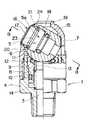
【図1】本発明に係る管継手を構成するソケットの実施の形態の一例を示す平面図。
【図2】図1のA−A線一部断面図。
【図3】図2のB−B線端面図。
【図4】本発明に係る管継手を構成するプラグの実施の形態の一例を示す断面図。
【図5】ソケットのボールバルブの貫通孔に図4に示すプラグを挿入した状態を示す断面図。
【図6】ソケットと図4に示すプラグを接続した状態を示す断面図。
【符号の説明】
1 ソケット
2 プラグ
3 流体通路
4 主筒体
5 貫通孔
5a プラグ挿入側開口部
6 ボールバルブ
7 ケーシング
8 大径凹部
9 シール保持部材
10 シールリング
11 ボールバルブ受け面
12 シールリング
13 カラー
14 スプリング
15 シールリング
16 プラグ挿通長孔
17 ケーシング側面開口部
18 ケーシング頂部開口部
19 嵌合突起
20 スプリング
21 ロック体
22 突起
23 係止段部
24 係止段部
25 流体通路
26 抜け止め膨出部
27 ロック部材
28 スプリング
29 ストップリング[0001]
BACKGROUND OF THE INVENTION
The present invention relates to a pipe joint including a plug and a socket provided with a ball valve.
[0002]
[Prior art]
Conventionally, as this kind of pipe joint, it consists of a socket and a plug connected to each other, and in the socket, a ball valve in which a through-hole into which the plug is inserted is formed, and the inside as a fluid passage An annular sealing member concentrically with the fluid passage is provided on the ball valve receiving surface formed at the tip of the sealing member, and the ball valve is rotatably surrounded and supported by the ball valve. A casing fixed to the main cylinder, and a plug insertion slot for inserting the plug into the through hole of the ball valve is opened from the side to the top of the casing. The casing side opening portion is a wide portion and the top opening portion is a narrow portion, and the plug has a wide portion of the plug insertion long hole on the outer periphery thereof. It has a bulging part that can be inserted into the lug insertion long hole and locks to the side edge of the plug insertion long hole at the narrow part, and the plug is made into the through hole of the ball valve at the wide part of the plug insertion long hole. Inserting and rotating the plug from this state to the narrow part at the top of the plug insertion long hole connects the plug and the socket, and the rotation of the plug also rotates the ball valve so that the plug is inserted into the plug. There is a known pipe joint in which the through hole of the ball valve and the fluid passage of the main cylinder coincide with each other and the fluid passage of the main cylinder and the fluid passage of the plug communicate when rotated to the narrow portion at the top of the long hole. It has been.
[0003]
[Problems to be solved by the invention]
However, according to the pipe joint having the above-described structure, the ball valve surrounded by the casing and supported by the main cylindrical body is rotatable, and is not regulated in the rotation direction. For example, when an impact is applied to a socket to which a plug is not connected for some reason, the ball valve is rotated by this impact and the through hole does not face the plug insertion long hole of the casing, that is, the plug It may become difficult to insert the plug from the plug insertion long hole into the through hole of the ball valve due to the disengagement from the insertion long hole. There is a problem that the ball valve may open. In addition, as long as the condition that the outer diameter of the plug is smaller than the through-hole of the ball valve is satisfied, the plug can be inserted into the through-hole of the ball valve. There was a problem that the through-hole could be opened by rotating.
[0004]
The object of the present invention is to restrict the movement of the ball valve when the plug is not connected, to ensure the connection of the plug, to prevent the malfunction of the ball valve, and to It is to provide a pipe joint that enables connection.
[0005]
[Means for Solving the Problems]
In order to achieve the above object, the invention according to claim 1 is a ball valve comprising a socket and a plug connected to each other, wherein the socket has a through hole into which the plug is inserted. A main cylinder having an internal fluid passage, an annular seal member concentric with the fluid passage at the tip, and the ball valve disposed on a ball valve receiving surface formed at the tip of the seal member; and the ball valve The casing is fixed to a main cylinder body that is rotatably surrounded and supported, and the casing has a plug insertion long hole for inserting the plug into the through hole of the ball valve from the side surface to the top of the casing. Opening, the casing side opening of the plug insertion long hole is a wide part, and the casing top opening is a narrow part. The plug insertion long hole has a retaining bulge that can be inserted into the plug insertion long hole at the casing side opening of the plug insertion long hole and that is locked to the side edge of the plug insertion long hole at the casing top opening. The plug is inserted into the through hole of the ball valve at the casing side opening and the plug is rotated from this state to the casing top opening of the plug insertion long hole so that the plug and the socket are connected. The ball valve is also rotated by the above, and when the plug is rotated to the casing top opening of the plug insertion long hole, the through hole of the ball valve and the fluid passage of the main cylinder coincide with each other, and the fluid passage of the main cylinderin the pipe joint and the fluid passage of the plug is in communication, the ball biased lock member in a forward direction by a spring in the through hole of the valve is provided retractably, the lock body the baud When the plug insertion side opening of the through hole of the valve is at the position on the casing side opening, the valve can be engaged with the peripheral edge of the casing side opening to prevent the ball valve from rotating, The ball valve is configured to be pushed and retracted by insertion of a plug into the through hole of the ball valve so as to be disengaged from the peripheral edge of the opening on the side surface of the casing and to turn the ball valve.
[0006]
According to this configuration, when the plug insertion side opening of the through hole of the ball valve is located at the casing side opening side of the plug insertion long hole, the lock body provided in the through hole of the ball valve is attached by the spring. The ball valve is forwardly moved and can be locked to the peripheral edge of the casing top opening of the plug insertion long hole that opens in the casing. When the force is applied, the advancing lock body is locked to the peripheral edge of the casing side opening, preventing the ball valve from rotating, and the ball valve through hole can be plugged The ball valve is prevented from being opened. Then, when the plug is connected, when the plug is inserted into the through hole of the ball valve, the advancing lock body is pushed by the plug and moves backward to disengage from the peripheral edge of the casing side opening, and the ball valve rotates. Therefore, the plug and the socket can be connected by rotating the plug inserted into the through hole of the ball valve to the casing top surface opening of the plug insertion long hole. When separating the plug from the socket, it can be separated by rotating the plug to the casing side opening of the plug insertion long hole and pulling the plug out of the through hole of the ball valve, but when the plug is pulled out of the through hole of the ball valve, The lock body moves forward by the spring force, which prevents the ball valve from rotating, and the through hole of the ball valve is held in a state where the plug can be inserted, so that the plug can be securely reconnected. And
[0007]
According to a second aspect of the present invention, the lock body according to the first aspect is formed of a cylindrical body that is provided so as to be able to advance and retreat in a through hole of a ball valve, and an outer diameter on a tip side thereof is the plug insertion long hole. The inner diameter of the lock body made of the cylindrical body is set to be smaller than the inner diameter of the casing side opening that is the wide width portion of the casing, and the inner diameter is set so that the plug can be fitted. A locking step for locking to a protrusion formed on the outer peripheral surface protrudes, and protrudes on the inner peripheral surface of the lock body fitted to the outer periphery of the plug by inserting the plug into the through hole of the ball valve. The latching step portion is configured to be latched and pushed by a protrusion formed on the outer peripheral surface of the plug so as to move backward.
[0008]
According to such a configuration, the plug to be connected has an outer diameter and an outer peripheral surface shape depending on an inner diameter and an inner peripheral surface shape of the lock body formed of a cylindrical body slidably provided in the through hole of the ball valve. Since it is regulated, it is possible to specify a plug to be connected and to prevent an inappropriate plug connection.
[0009]
DETAILED DESCRIPTION OF THE INVENTION
Hereinafter, an example of an embodiment of a pipe joint concerning the present invention is explained in detail with reference to drawings. 1 to 3 show an example of a socket constituting the pipe joint according to the present invention, and FIG. 4 shows an example of a plug constituting the pipe joint according to the present invention.
[0010]
In the drawings, 1 is a socket, and 2 is a plug connected to the socket 1. The socket 1 includes a
[0011]
The main
[0012]
In the
[0013]
In the relationship between the plug insertion
[0014]
Further, a
[0015]
Further, a
[0016]
In this example, the
[0017]
Further, a locking
[0018]
A locking
[0019]
The
[0020]
Further, the
[0021]
The
[0022]
When the
[0023]
According to the pipe joint thus configured, the
[0024]
When the
[0025]
When the
[0026]
Further, in this example, the
[0027]
【The invention's effect】
As described above, according to the pipe joint according to the present invention, when the plug is not connected to the socket, the lock of the ball valve of the socket is prevented by the lock body. Even if a force to rotate the ball valve is applied, the through hole of the ball valve is held in an open state on the side of the casing side opening through which the plug can be inserted. It is possible to reliably prevent the connection of the ball from being difficult or the ball valve from opening.
[0028]
Further, if the outer diameter and shape of the plug are restricted with the lock body, the plug to be connected can be specified, and inappropriate plug connection can be prevented.
[Brief description of the drawings]
FIG. 1 is a plan view showing an example of an embodiment of a socket constituting a pipe joint according to the present invention.
FIG. 2 is a partial cross-sectional view taken along line AA in FIG.
FIG. 3 is an end view taken along line BB in FIG. 2;
FIG. 4 is a sectional view showing an example of an embodiment of a plug constituting the pipe joint according to the present invention.
5 is a cross-sectional view showing a state in which the plug shown in FIG. 4 is inserted into the through hole of the ball valve of the socket.
6 is a cross-sectional view showing a state in which the socket and the plug shown in FIG. 4 are connected.
[Explanation of symbols]
DESCRIPTION OF SYMBOLS 1
Claims (2)
Translated fromJapanese前記ボールバルブの貫通孔内にスプリングで前進方向に付勢されたロック体が進退自在に設けられ、該ロック体は前記ボールバルブの貫通孔のプラグ挿入側開口部が前記ケーシング側面開口部側の位置にあるとき前進してケーシング側面開口部の周端縁に係止可能となってボールバルブの回動を阻止し、前記ボールバルブの貫通孔へのプラグの挿入により押され後退して前記ケーシング側面開口部の周端縁から外れボールバルブの回動を可能にするように構成されていることを特徴とする管継手。The socket is composed of a socket and a plug connected to each other. The socket has a ball valve in which a through-hole into which the plug is inserted is formed. A main cylinder in which a ball valve is disposed on a ball valve receiving surface formed at a tip of the seal member, and a casing fixed to the main cylinder that surrounds and supports the ball valve in a rotatable manner. In the casing, a plug insertion long hole for inserting the plug into the through hole of the ball valve is opened from the side of the casing to the top, and the casing side opening of the plug insertion long hole is a wide portion. The casing top opening is a narrow part, and the plug is plugged at the casing side opening of the plug insertion long hole on the outer periphery of the plug. Has a retaining bulge that can be inserted into the through hole and locked to the side edge of the plug insertion long hole at the opening at the top of the casing. The plug penetrates the ball valve through the casing side opening of the plug insertion long hole. The plug is inserted into the hole, and from this state, the plug is rotated to the casing top opening of the plug insertion long hole, so that the plug and the socket are connected, and the ball valve is also rotated by the rotation of the plug. In the pipe jointin which the through hole of the ball valve and the fluid passage of the main cylinder coincide with each other, and the fluid passage of the main cylinder communicates with the fluid passage of the plug when rotated to the casing top opening of the insertion long hole.
A lock body urged in a forward direction by a spring is provided in the through hole of the ball valve so as to be able to advance and retreat. The lock body has a plug insertion side opening of the through hole of the ball valve on the side of the casing side opening. It moves forward when it is in position and can be locked to the peripheral edge of the opening on the side of the casing to prevent the ball valve from rotating, and it is pushed back by insertion of the plug into the through hole of the ball valve and retracts to the casing. A pipe joint configured to be disengaged from the peripheral edge of the side opening and to enable rotation of the ball valve.
Priority Applications (2)
| Application Number | Priority Date | Filing Date | Title |
|---|---|---|---|
| JP2002189719AJP3677491B2 (en) | 2002-06-28 | 2002-06-28 | Pipe fitting |
| US10/608,947US6827329B2 (en) | 2002-06-28 | 2003-06-26 | Pipe coupling |
Applications Claiming Priority (1)
| Application Number | Priority Date | Filing Date | Title |
|---|---|---|---|
| JP2002189719AJP3677491B2 (en) | 2002-06-28 | 2002-06-28 | Pipe fitting |
Publications (2)
| Publication Number | Publication Date |
|---|---|
| JP2004028310A JP2004028310A (en) | 2004-01-29 |
| JP3677491B2true JP3677491B2 (en) | 2005-08-03 |
Family
ID=31184050
Family Applications (1)
| Application Number | Title | Priority Date | Filing Date |
|---|---|---|---|
| JP2002189719AExpired - Fee RelatedJP3677491B2 (en) | 2002-06-28 | 2002-06-28 | Pipe fitting |
Country Status (2)
| Country | Link |
|---|---|
| US (1) | US6827329B2 (en) |
| JP (1) | JP3677491B2 (en) |
Families Citing this family (21)
| Publication number | Priority date | Publication date | Assignee | Title |
|---|---|---|---|---|
| PT1364149E (en)* | 2001-03-01 | 2006-06-30 | Oetiker Hans Maschinen | ENGAGEMENT SECURITY COUPLING |
| AU2004315283B2 (en)* | 2004-01-09 | 2008-05-29 | Hans Oetiker Ag Maschinen-Und Apparatefabrik | Plug-in safety coupling for pressure pipes, comprising a pivoted blocking member |
| FR2884896B1 (en) | 2005-04-26 | 2007-06-29 | Prospection Et D Inv S Techniq | SEALING CONNECTION AND ASSEMBLY OF A TRANSMISSION MEMBER, A GAS CARTRIDGE AND AN ADAPTER COMPRISING THE CONNECTION |
| FR2884892B1 (en)* | 2005-04-26 | 2010-05-21 | Prospection & Inventions | ASSEMBLY OF AN ENERGY TRANSMISSION DEVICE OF A MANUALLY ACTUATED APPARATUS AND AN ENERGY SOURCE HAVING ROTATION LOCKING AND ANGULAR INDEXING OF THE SOURCE |
| US7857284B2 (en) | 2006-04-11 | 2010-12-28 | Nypro Inc. | Medical valve with movable member |
| ATE440241T1 (en)* | 2007-02-07 | 2009-09-15 | Albrecht Wutrich | SAFETY COUPLING FOR COMPRESSED AIR LINES |
| US7767637B2 (en)* | 2007-05-16 | 2010-08-03 | Babcock & Wilcox Technical Services Y-12, Llc | Solvent for urethane adhesives and coatings and method of use |
| JP5836939B2 (en) | 2009-06-22 | 2015-12-24 | エヌピー メディカル インコーポレイテッド | Medical valve with improved back pressure seal |
| US9138572B2 (en) | 2010-06-24 | 2015-09-22 | Np Medical Inc. | Medical valve with fluid volume alteration |
| CH705400A1 (en)* | 2011-08-18 | 2013-02-28 | Albrecht Wuethrich | Combination of stop valve and quick coupler for use during transition of stationary lines to mobile pressure lines in building industry, has locking body brought from locking position into guiding position by actuation valve |
| CN103062509A (en)* | 2011-10-24 | 2013-04-24 | 中国航空工业集团公司沈阳发动机设计研究所 | Double-ball angle sealing structure used for penetrating through cartridge receiver |
| US9737686B2 (en)* | 2012-03-12 | 2017-08-22 | Becton, Dickinson And Company | Catheter adapter port valve |
| JP5832349B2 (en)* | 2012-03-28 | 2015-12-16 | 日東工器株式会社 | Pipe fitting |
| JP5854907B2 (en)* | 2012-03-28 | 2016-02-09 | 日東工器株式会社 | Pipe fitting |
| US10207100B2 (en)* | 2012-06-07 | 2019-02-19 | Quest Medical, Inc. | Injection port with articulated stopcock |
| US20140110934A1 (en)* | 2012-10-22 | 2014-04-24 | Airgo Ip, Llc | Fluid-tight flexural joint |
| GB2518163A (en) | 2013-09-11 | 2015-03-18 | Inspired Designs Ltd | Tubular couplings and connectors |
| JP6706727B2 (en)* | 2014-07-03 | 2020-06-10 | ダイセン株式会社 | Fluid fitting |
| JP6039045B2 (en)* | 2015-12-07 | 2016-12-07 | 日東工器株式会社 | Pipe fitting |
| CN111902665B (en) | 2017-12-07 | 2022-11-01 | 泰科消防产品有限合伙公司 | Adjustable swivel |
| JP7281360B2 (en)* | 2019-08-06 | 2023-05-25 | 日東工器株式会社 | female fittings and pipe fittings |
Family Cites Families (11)
| Publication number | Priority date | Publication date | Assignee | Title |
|---|---|---|---|---|
| US62872A (en)* | 1867-03-12 | Improved strainer | ||
| US2493271A (en)* | 1948-06-19 | 1950-01-03 | Milton J Smith | Valved hose coupling |
| FR2482696B1 (en)* | 1980-05-13 | 1985-09-20 | Staubli Sa Ets | IMPROVEMENTS ON SAFETY VALVE CONNECTIONS |
| US5326072A (en)* | 1988-02-03 | 1994-07-05 | Hans Oetiker Ag, Maschinen-Und Apparatefabrik | Plug-in safety coupling, in particular for compressed air lines |
| IL87280A (en)* | 1988-08-01 | 1991-01-31 | Dolev Moshe | Quick-disconnect hose coupling device |
| SE465181B (en)* | 1989-06-29 | 1991-08-05 | Atlas Copco Tools Ab | QUICK CONNECTION WITH TURNING VALVE |
| US5562273A (en)* | 1989-09-27 | 1996-10-08 | Han Oetiker Ag Maschinen- & Apparatefabrik | Plug-in coupling for pressure lines |
| US4982929A (en)* | 1990-03-06 | 1991-01-08 | Spurling Daniel P | Safety valve coupling |
| CN1040357C (en)* | 1993-01-22 | 1998-10-21 | 汉斯厄蒂克股份公司机械设备厂 | Pluggable safety connectors for pressure medium conduits |
| JP3383560B2 (en)* | 1997-10-06 | 2003-03-04 | 日東工器株式会社 | Pipe fittings |
| JP3514724B2 (en)* | 2000-11-29 | 2004-03-31 | 日東工器株式会社 | Pipe fittings |
- 2002
- 2002-06-28JPJP2002189719Apatent/JP3677491B2/ennot_activeExpired - Fee Related
- 2003
- 2003-06-26USUS10/608,947patent/US6827329B2/ennot_activeExpired - Lifetime
Also Published As
| Publication number | Publication date |
|---|---|
| US6827329B2 (en) | 2004-12-07 |
| JP2004028310A (en) | 2004-01-29 |
| US20040051070A1 (en) | 2004-03-18 |
Similar Documents
| Publication | Publication Date | Title |
|---|---|---|
| JP3677491B2 (en) | Pipe fitting | |
| JP3313675B2 (en) | Socket for fittings | |
| JP3514724B2 (en) | Pipe fittings | |
| JP5317760B2 (en) | Socket for pipe joint and pipe joint | |
| JP3829117B2 (en) | Pipe fitting | |
| JP5317761B2 (en) | Socket for pipe joint and pipe joint | |
| JP2004278620A (en) | Pipe fittings | |
| JP3496977B2 (en) | Pipe fittings | |
| JP3615190B2 (en) | Socket for fittings | |
| JP2004293568A (en) | Pipe joint | |
| JP3415521B2 (en) | Pipe fitting | |
| JPH0234553Y2 (en) | ||
| JP2004293568A5 (en) | ||
| JP7029301B2 (en) | Pipe fittings | |
| JP5832349B2 (en) | Pipe fitting | |
| JP2004100911A (en) | Socket for fittings | |
| JPH0733031Y2 (en) | Pipe fitting | |
| JP4011263B2 (en) | Pipe fitting | |
| JPH10238679A (en) | Connector for gas cock | |
| JP7281360B2 (en) | female fittings and pipe fittings | |
| JP3865673B2 (en) | Fitting socket | |
| JP4369564B2 (en) | Pipe fitting | |
| JPH1113977A (en) | Freely attachable/detachable pipe joint | |
| JP3311884B2 (en) | Pipe fittings | |
| JPS5824070Y2 (en) | pipe fittings |
Legal Events
| Date | Code | Title | Description |
|---|---|---|---|
| A131 | Notification of reasons for refusal | Free format text:JAPANESE INTERMEDIATE CODE: A131 Effective date:20050118 | |
| A521 | Request for written amendment filed | Free format text:JAPANESE INTERMEDIATE CODE: A523 Effective date:20050318 | |
| TRDD | Decision of grant or rejection written | ||
| A01 | Written decision to grant a patent or to grant a registration (utility model) | Free format text:JAPANESE INTERMEDIATE CODE: A01 Effective date:20050426 | |
| A61 | First payment of annual fees (during grant procedure) | Free format text:JAPANESE INTERMEDIATE CODE: A61 Effective date:20050509 | |
| R150 | Certificate of patent or registration of utility model | Ref document number:3677491 Country of ref document:JP Free format text:JAPANESE INTERMEDIATE CODE: R150 Free format text:JAPANESE INTERMEDIATE CODE: R150 | |
| FPAY | Renewal fee payment (event date is renewal date of database) | Free format text:PAYMENT UNTIL: 20090513 Year of fee payment:4 | |
| R250 | Receipt of annual fees | Free format text:JAPANESE INTERMEDIATE CODE: R250 | |
| FPAY | Renewal fee payment (event date is renewal date of database) | Free format text:PAYMENT UNTIL: 20100513 Year of fee payment:5 | |
| R250 | Receipt of annual fees | Free format text:JAPANESE INTERMEDIATE CODE: R250 | |
| FPAY | Renewal fee payment (event date is renewal date of database) | Free format text:PAYMENT UNTIL: 20100513 Year of fee payment:5 | |
| FPAY | Renewal fee payment (event date is renewal date of database) | Free format text:PAYMENT UNTIL: 20110513 Year of fee payment:6 | |
| R250 | Receipt of annual fees | Free format text:JAPANESE INTERMEDIATE CODE: R250 | |
| FPAY | Renewal fee payment (event date is renewal date of database) | Free format text:PAYMENT UNTIL: 20110513 Year of fee payment:6 | |
| FPAY | Renewal fee payment (event date is renewal date of database) | Free format text:PAYMENT UNTIL: 20120513 Year of fee payment:7 | |
| R250 | Receipt of annual fees | Free format text:JAPANESE INTERMEDIATE CODE: R250 | |
| FPAY | Renewal fee payment (event date is renewal date of database) | Free format text:PAYMENT UNTIL: 20120513 Year of fee payment:7 | |
| FPAY | Renewal fee payment (event date is renewal date of database) | Free format text:PAYMENT UNTIL: 20130513 Year of fee payment:8 | |
| R250 | Receipt of annual fees | Free format text:JAPANESE INTERMEDIATE CODE: R250 | |
| FPAY | Renewal fee payment (event date is renewal date of database) | Free format text:PAYMENT UNTIL: 20140513 Year of fee payment:9 | |
| R250 | Receipt of annual fees | Free format text:JAPANESE INTERMEDIATE CODE: R250 | |
| R250 | Receipt of annual fees | Free format text:JAPANESE INTERMEDIATE CODE: R250 | |
| R250 | Receipt of annual fees | Free format text:JAPANESE INTERMEDIATE CODE: R250 | |
| R250 | Receipt of annual fees | Free format text:JAPANESE INTERMEDIATE CODE: R250 | |
| R250 | Receipt of annual fees | Free format text:JAPANESE INTERMEDIATE CODE: R250 | |
| R250 | Receipt of annual fees | Free format text:JAPANESE INTERMEDIATE CODE: R250 | |
| R250 | Receipt of annual fees | Free format text:JAPANESE INTERMEDIATE CODE: R250 | |
| R250 | Receipt of annual fees | Free format text:JAPANESE INTERMEDIATE CODE: R250 | |
| R250 | Receipt of annual fees | Free format text:JAPANESE INTERMEDIATE CODE: R250 | |
| LAPS | Cancellation because of no payment of annual fees |