JP3677298B2 - Automatic chemical analyzer - Google Patents
Automatic chemical analyzerDownload PDFInfo
- Publication number
- JP3677298B2 JP3677298B2JP50441598AJP50441598AJP3677298B2JP 3677298 B2JP3677298 B2JP 3677298B2JP 50441598 AJP50441598 AJP 50441598AJP 50441598 AJP50441598 AJP 50441598AJP 3677298 B2JP3677298 B2JP 3677298B2
- Authority
- JP
- Japan
- Prior art keywords
- sample
- reagent
- probe
- station
- cuvette
- Prior art date
- Legal status (The legal status is an assumption and is not a legal conclusion. Google has not performed a legal analysis and makes no representation as to the accuracy of the status listed.)
- Expired - Fee Related
Links
Images


Classifications
- G—PHYSICS
- G01—MEASURING; TESTING
- G01N—INVESTIGATING OR ANALYSING MATERIALS BY DETERMINING THEIR CHEMICAL OR PHYSICAL PROPERTIES
- G01N35/00—Automatic analysis not limited to methods or materials provided for in any single one of groups G01N1/00 - G01N33/00; Handling materials therefor
- G01N35/00584—Control arrangements for automatic analysers
- G01N35/00594—Quality control, including calibration or testing of components of the analyser
- G—PHYSICS
- G01—MEASURING; TESTING
- G01N—INVESTIGATING OR ANALYSING MATERIALS BY DETERMINING THEIR CHEMICAL OR PHYSICAL PROPERTIES
- G01N35/00—Automatic analysis not limited to methods or materials provided for in any single one of groups G01N1/00 - G01N33/00; Handling materials therefor
- G01N35/00584—Control arrangements for automatic analysers
- G01N35/0092—Scheduling
- G—PHYSICS
- G01—MEASURING; TESTING
- G01N—INVESTIGATING OR ANALYSING MATERIALS BY DETERMINING THEIR CHEMICAL OR PHYSICAL PROPERTIES
- G01N35/00—Automatic analysis not limited to methods or materials provided for in any single one of groups G01N1/00 - G01N33/00; Handling materials therefor
- G01N35/02—Automatic analysis not limited to methods or materials provided for in any single one of groups G01N1/00 - G01N33/00; Handling materials therefor using a plurality of sample containers moved by a conveyor system past one or more treatment or analysis stations
- G01N35/025—Automatic analysis not limited to methods or materials provided for in any single one of groups G01N1/00 - G01N33/00; Handling materials therefor using a plurality of sample containers moved by a conveyor system past one or more treatment or analysis stations having a carousel or turntable for reaction cells or cuvettes
- G—PHYSICS
- G01—MEASURING; TESTING
- G01N—INVESTIGATING OR ANALYSING MATERIALS BY DETERMINING THEIR CHEMICAL OR PHYSICAL PROPERTIES
- G01N35/00—Automatic analysis not limited to methods or materials provided for in any single one of groups G01N1/00 - G01N33/00; Handling materials therefor
- G01N2035/00178—Special arrangements of analysers
- G01N2035/00277—Special precautions to avoid contamination (e.g. enclosures, glove- boxes, sealed sample carriers, disposal of contaminated material)
- G—PHYSICS
- G01—MEASURING; TESTING
- G01N—INVESTIGATING OR ANALYSING MATERIALS BY DETERMINING THEIR CHEMICAL OR PHYSICAL PROPERTIES
- G01N35/00—Automatic analysis not limited to methods or materials provided for in any single one of groups G01N1/00 - G01N33/00; Handling materials therefor
- G01N2035/00465—Separating and mixing arrangements
- G01N2035/00534—Mixing by a special element, e.g. stirrer
- G—PHYSICS
- G01—MEASURING; TESTING
- G01N—INVESTIGATING OR ANALYSING MATERIALS BY DETERMINING THEIR CHEMICAL OR PHYSICAL PROPERTIES
- G01N35/00—Automatic analysis not limited to methods or materials provided for in any single one of groups G01N1/00 - G01N33/00; Handling materials therefor
- G01N35/00584—Control arrangements for automatic analysers
- G01N35/00722—Communications; Identification
- G01N35/00732—Identification of carriers, materials or components in automatic analysers
- G01N2035/00742—Type of codes
- G01N2035/00752—Type of codes bar codes
- G—PHYSICS
- G01—MEASURING; TESTING
- G01N—INVESTIGATING OR ANALYSING MATERIALS BY DETERMINING THEIR CHEMICAL OR PHYSICAL PROPERTIES
- G01N35/00—Automatic analysis not limited to methods or materials provided for in any single one of groups G01N1/00 - G01N33/00; Handling materials therefor
- G01N35/00584—Control arrangements for automatic analysers
- G01N35/0092—Scheduling
- G01N2035/0093—Scheduling random access not determined by physical position
- G—PHYSICS
- G01—MEASURING; TESTING
- G01N—INVESTIGATING OR ANALYSING MATERIALS BY DETERMINING THEIR CHEMICAL OR PHYSICAL PROPERTIES
- G01N35/00—Automatic analysis not limited to methods or materials provided for in any single one of groups G01N1/00 - G01N33/00; Handling materials therefor
- G01N35/02—Automatic analysis not limited to methods or materials provided for in any single one of groups G01N1/00 - G01N33/00; Handling materials therefor using a plurality of sample containers moved by a conveyor system past one or more treatment or analysis stations
- G01N35/04—Details of the conveyor system
- G01N2035/0401—Sample carriers, cuvettes or reaction vessels
- G01N2035/0437—Cleaning cuvettes or reaction vessels
- G—PHYSICS
- G01—MEASURING; TESTING
- G01N—INVESTIGATING OR ANALYSING MATERIALS BY DETERMINING THEIR CHEMICAL OR PHYSICAL PROPERTIES
- G01N35/00—Automatic analysis not limited to methods or materials provided for in any single one of groups G01N1/00 - G01N33/00; Handling materials therefor
- G01N35/02—Automatic analysis not limited to methods or materials provided for in any single one of groups G01N1/00 - G01N33/00; Handling materials therefor using a plurality of sample containers moved by a conveyor system past one or more treatment or analysis stations
- G01N35/04—Details of the conveyor system
- G01N2035/0439—Rotary sample carriers, i.e. carousels
- G01N2035/0446—Combinations of the above
- G01N2035/0448—Combinations of the above composed of interchangeable ring elements
- G—PHYSICS
- G01—MEASURING; TESTING
- G01N—INVESTIGATING OR ANALYSING MATERIALS BY DETERMINING THEIR CHEMICAL OR PHYSICAL PROPERTIES
- G01N35/00—Automatic analysis not limited to methods or materials provided for in any single one of groups G01N1/00 - G01N33/00; Handling materials therefor
- G01N35/02—Automatic analysis not limited to methods or materials provided for in any single one of groups G01N1/00 - G01N33/00; Handling materials therefor using a plurality of sample containers moved by a conveyor system past one or more treatment or analysis stations
- G01N35/04—Details of the conveyor system
- G01N2035/0439—Rotary sample carriers, i.e. carousels
- G01N2035/0451—Rotary sample carriers, i.e. carousels composed of interchangeable sectors
- G—PHYSICS
- G01—MEASURING; TESTING
- G01N—INVESTIGATING OR ANALYSING MATERIALS BY DETERMINING THEIR CHEMICAL OR PHYSICAL PROPERTIES
- G01N35/00—Automatic analysis not limited to methods or materials provided for in any single one of groups G01N1/00 - G01N33/00; Handling materials therefor
- G01N35/00584—Control arrangements for automatic analysers
- G01N35/00594—Quality control, including calibration or testing of components of the analyser
- G01N35/00693—Calibration
- Y—GENERAL TAGGING OF NEW TECHNOLOGICAL DEVELOPMENTS; GENERAL TAGGING OF CROSS-SECTIONAL TECHNOLOGIES SPANNING OVER SEVERAL SECTIONS OF THE IPC; TECHNICAL SUBJECTS COVERED BY FORMER USPC CROSS-REFERENCE ART COLLECTIONS [XRACs] AND DIGESTS
- Y10—TECHNICAL SUBJECTS COVERED BY FORMER USPC
- Y10T—TECHNICAL SUBJECTS COVERED BY FORMER US CLASSIFICATION
- Y10T436/00—Chemistry: analytical and immunological testing
- Y10T436/11—Automated chemical analysis
- Y10T436/113332—Automated chemical analysis with conveyance of sample along a test line in a container or rack
- Y10T436/114165—Automated chemical analysis with conveyance of sample along a test line in a container or rack with step of insertion or removal from test line
- Y—GENERAL TAGGING OF NEW TECHNOLOGICAL DEVELOPMENTS; GENERAL TAGGING OF CROSS-SECTIONAL TECHNOLOGIES SPANNING OVER SEVERAL SECTIONS OF THE IPC; TECHNICAL SUBJECTS COVERED BY FORMER USPC CROSS-REFERENCE ART COLLECTIONS [XRACs] AND DIGESTS
- Y10—TECHNICAL SUBJECTS COVERED BY FORMER USPC
- Y10T—TECHNICAL SUBJECTS COVERED BY FORMER US CLASSIFICATION
- Y10T436/00—Chemistry: analytical and immunological testing
- Y10T436/11—Automated chemical analysis
- Y10T436/113332—Automated chemical analysis with conveyance of sample along a test line in a container or rack
- Y10T436/114998—Automated chemical analysis with conveyance of sample along a test line in a container or rack with treatment or replacement of aspirator element [e.g., cleaning, etc.]
- Y—GENERAL TAGGING OF NEW TECHNOLOGICAL DEVELOPMENTS; GENERAL TAGGING OF CROSS-SECTIONAL TECHNOLOGIES SPANNING OVER SEVERAL SECTIONS OF THE IPC; TECHNICAL SUBJECTS COVERED BY FORMER USPC CROSS-REFERENCE ART COLLECTIONS [XRACs] AND DIGESTS
- Y10—TECHNICAL SUBJECTS COVERED BY FORMER USPC
- Y10T—TECHNICAL SUBJECTS COVERED BY FORMER US CLASSIFICATION
- Y10T436/00—Chemistry: analytical and immunological testing
- Y10T436/11—Automated chemical analysis
- Y10T436/115831—Condition or time responsive
- Y—GENERAL TAGGING OF NEW TECHNOLOGICAL DEVELOPMENTS; GENERAL TAGGING OF CROSS-SECTIONAL TECHNOLOGIES SPANNING OVER SEVERAL SECTIONS OF THE IPC; TECHNICAL SUBJECTS COVERED BY FORMER USPC CROSS-REFERENCE ART COLLECTIONS [XRACs] AND DIGESTS
- Y10—TECHNICAL SUBJECTS COVERED BY FORMER USPC
- Y10T—TECHNICAL SUBJECTS COVERED BY FORMER US CLASSIFICATION
- Y10T436/00—Chemistry: analytical and immunological testing
- Y10T436/11—Automated chemical analysis
- Y10T436/119163—Automated chemical analysis with aspirator of claimed structure
Landscapes
- Chemical & Material Sciences (AREA)
- General Physics & Mathematics (AREA)
- Pathology (AREA)
- Health & Medical Sciences (AREA)
- Life Sciences & Earth Sciences (AREA)
- Analytical Chemistry (AREA)
- Biochemistry (AREA)
- Physics & Mathematics (AREA)
- General Health & Medical Sciences (AREA)
- Immunology (AREA)
- Chemical Kinetics & Catalysis (AREA)
- Engineering & Computer Science (AREA)
- Quality & Reliability (AREA)
- Automatic Analysis And Handling Materials Therefor (AREA)
- Organic Low-Molecular-Weight Compounds And Preparation Thereof (AREA)
- Sampling And Sample Adjustment (AREA)
- Analysing Materials By The Use Of Radiation (AREA)
Abstract
Description
Translated fromJapanese発明の分野
本発明は、自動臨床化学分析装置の分野に関し、特に、比濁計を使用したコンパクトな自動化学分析装置に関する。
発明の背景
この技術分野において、多数の異なる自動臨床化学分析装置(自動臨床化学アナライザ)が知られている。このような分析器は、簡単でかつ主に手動の機器から非常に複雑で、ほぼ完全に自動化された機器までの範囲である。各分析装置は、分析装置が実行することができる異なる試験の数(メニュー)および所定時間に分析装置が処理することができるサンプルの数(スループット)に関連するそれ自身の性能特性を有する。
今日の自動分析装置の多くは精巧で効率がよいが、いくつかの問題が存在し続けている。第1番目の問題は、スループット容量である。1個のサンプルの分析時間で節減することができる1秒毎に、数百万ドルの高価な医薬資源が節減されることを意味する。したがって、スループットを増大するために分析装置のメーカーへ連続的な圧力がかかる。従来技術の自動化された分析装置は非常に高速であるが、十分に高速なわけではない。
従来技術の他の問題は、操作上のコストである。従来技術の最も自動化された分析装置は、大量の高価な試薬材料を必要とする比較的大きな反応容器(キュベット)を使用する。
更に従来技術の他の問題は、操作者が分析装置にデータおよび指示をを入力するのに費やさなければならない時間の量である。これは、スループットを減少させ、過剰な人員の費用を生じる。
スループットに関する他の問題は、比濁計を調整するために動作を周期的に遮断する、比濁計分析装置を使用した従来技術の分析装置の必要性である。
最後に、従来技術の自動分析装置に使用される真空ドレン装置のスループットに関する問題である。このような真空ドレン装置は、一般的に真空操作の使用に関して不経済である。このような浪費は、非常にたくさんの真空操作を行い、分析装置のスループットを減少する。
したがって、従来技術の分析装置のモジュールより大きなスループットを有し、操作要員が少なくて済み、さらに信頼性および有効性の高いな自動臨床化学分析装置が必要である。
発明の概要
本発明はこれらの必要性を満足する。本発明は、
(a)本体と、
(b)前記本体内に配置されかつモータによって作動されるサンプルステーションであって、複数のサンプル容器を保持し、サンプル抽出場所を備える寸法と大きさであり、前記サンプルステーションが複数のサンプル容器を保持するとき、個々のサンプル容器がサンプル抽出場所に向かって、または前記抽出場所から離れるように交互に移動することができるように、前記本体内で可動であるサンプルステーションと、
(c)前記本体内に配置されかつモータで駆動される試薬ステーションであって、複数の試薬容器を保持し、試薬抽出場所を備える寸法と大きさであり、前記試薬ステーションが複数の試薬容器を保持するとき、個々の試薬容器が試薬抽出場所に向かって、または前記試薬抽出場所から離れるように交互に移動することができるように、前記本体内で可動である試薬ステーションと、
(d)前記本体内に配置されかつモータで駆動されるランダムアクセス分析ステーションであって、複数の反応キュベットを保持する寸法と大きさであり、キュベット混合場所、キュベット洗浄場所、ランダムアクセス分析ステーション分析場所、および前記キュベット内に配置されたサンプルの少なくとも1個のパラメータを決定するランダムアクセス分析ステーション分析場所に接近して配置された分析器を有し、前記ランダムアクセス分析ステーションが複数のキュベットを保持するとき、個々のキュベットが(1)キュベット混合場所、(2)キュベット洗浄場所、および(3)前記ランダムアクセス分析ステーション分析場所に向かって、またはそこから離れるように交互に移動することができるように前記本体内で可動であるモータで駆動されるランダムアクセス分析ステーションと、
(e)前記本体内に取り付けられたサンプル・プローブ・アーム・アセンブリであって、(1)サンプル・プローブ・アームと、(2)内部チャンバ、開放した下端および開放した上端を有する中空のサンプルプローブと、(3)下端および上端を有する細長い回転可能なサンプル攪拌棒とを備え、前記サンプル攪拌棒の下端は、前記サンプル攪拌棒の下端に取り付けられたサンプル攪拌棒パドルを有し、前記サンプルプローブおよび前記サンプル攪拌棒は互いに緊密に接近して、ほぼ垂直方向に配置されており、前記サンプルプローブは、下方サンプルプローブ位置と上方サンプルプローブ位置との間で垂直方向に可動であり、前記サンプル攪拌棒は、下方のサンプル攪拌棒位置と上方のサンプル攪拌棒位置との間で前記サンプルプローブとは独立して可動であり、前記サンプルプローブおよび前記サンプル攪拌棒は、前記サンプルプローブが前記下方のサンプルプローブ位置にあり、前記サンプル攪拌棒が下方のサンプル攪拌棒位置にあるとき、前記サンプル・プローブ・アームは、前記サンプルプローブがサンプル抽出場所のすぐ上にある第1のサンプル・プローブ・アーム位置と、前記サンプルプローブが前記キュベット混合場所のすぐ上にある第2のサンプル・プローブ・アーム位置との間で可動であるようにサンプル・プローブ・アーム・アセンブリ内に配置されている、サンプル・プローブ・アーム・アセンブリと、
(f)前記下方サンプルプローブ位置と前記上方サンプルプローブ位置との間で前記サンプルプローブを移動するサンプルプローブ位置決めモータと、
(g)前記下方サンプル攪拌棒位置と前記上方サンプル攪拌棒位置との間で前記サンプル攪拌棒を移動するサンプル攪拌棒位置決めモータと、
(h)前記サンプル攪拌棒を回転するサンプル攪拌棒回転モータと、
(i)前記サンプルプローブの内部チャンバに正圧と負圧を交互に加えるサンプルプローブ圧力変更アセンブリと、
(j)前記本体に取り付けられた試薬プローブ・アーム・アセンブリであって、(1)試薬プローブアームと、(2)内部チャンバと、開放した下端および開放した上端を有する中空の試薬プローブと、(3)下端および上端を有する細長い回転可能な試薬攪拌棒とを有し、前記試薬攪拌棒の下端は、前記試薬攪拌棒の下端に取り付けられた試薬攪拌棒パドルを備え、前記試薬プローブおよび前記試薬攪拌棒は互いに緊密に接近して、ほぼ垂直方向に配置されており、前記試薬プローブは、下方試薬プローブ位置と上方試薬プローブ位置との間で垂直方向に可動であり、前記試薬攪拌棒は、下方の試薬攪拌棒位置と上方の試薬攪拌棒位置との間で前記試薬プローブとは独立して可動であり、前記試薬プローブおよび前記試薬攪拌棒は、前記試薬プローブが前記下方の試薬プローブ位置にありかつ前記試薬攪拌棒が前記下方の試薬攪拌棒位置にあるとき、前記試薬プローブアームが、前記試薬プローブが前記試薬抽出場所のすぐ上にある第1の試薬プローブアーム位置と前記試薬プローブが前記キュベット混合場所のすぐ上にある第2の試薬プローブアーム位置との間で可動であるように、試薬プローブ・アーム・アセンブリ内に配置されている試薬プローブ・アーム・アセンブリと、
(k)前記下方の試薬プローブ位置と前記上方の試薬プローブ位置との間で前記試薬プローブを移動する試薬プローブ位置決めモータと、
(l)前記下方の試薬攪拌棒位置と前記上方の試薬攪拌棒位置との間で前記試薬攪拌棒を移動する試薬攪拌棒位置決めモータと、
(m)前記試薬攪拌棒を回転する試薬攪拌棒回転モータと、
(n)前記試薬プローブの内部チャンバに正圧および負圧を交互に加える試薬プローブ圧力変更アセンブリと、
(o)前記本体に取り付けられたキュベット洗浄ステーションであって、内部チャンバ、開放した下端、および開放した上端を有する少なくとも1個のモータで作動される中空キュベット洗浄ステーションプローブを備え、前記キュベット洗浄ステーションプローブが前記キュベット洗浄場所のすぐ上になるように配置されるキュベット洗浄ステーションと、
(p)(1)前記キュベット洗浄場所で前記ランダムアクセス分析ステーション内に配置されたキュベットを洗浄するために前記キュベット洗浄ステーションプローブに洗浄液体源から加圧洗浄液体、または、(2)前記分析場所で前記ランダムアクセス分析ステーション内に配置されたキュベットから廃液を除去し、このような廃液を適切な廃棄場所に転送するために、前記キュベット洗浄ステーションプローブの内部チャンバに負圧を交互に送るキュベット洗浄ステーションプローブ供給源および廃棄アセンブリとを備える、液体サンプルの少なくとも1個のパラメータを決定する装置を提供する。
好ましくは、各プローブアームにおいて、それらの最下端位置における前記プローブと前記攪拌棒との間の距離は、約1.7mmと約5.3mmとの間、さらに好ましくは、約1.7mmと約3.5mmとの間、最も好ましくは、約1.7mmと3mmとの間である。
また、好ましくは、各プローブアームにおいて、前記プローブおよび攪拌棒は互いに独立して垂直方向に可動である。
好ましくは、各プローブおよび攪拌棒は、前記プローブおよび攪拌棒を昇降するためにラックおよびピニオンアセンブリによってそれらのプローブアームに取り付けられる。この特徴により、(それらの最下端位置で)前記プローブおよび攪拌棒の下端が互いに非常に接近しながら、前記プローブおよび攪拌棒の独立した動作が可能になる。同様にこれは、必要とする高価な試薬が最小量でよい、さらに小さい反応容器の使用を可能にする。
好ましい実施例において、前記サンプルステーションは、外壁を有する回転サンプルカルーセルを備え、前記外壁にはバーコード情報を表示するカード保持する、保持アセンブリが設けられている。これは、前記装置内に配置されたバーコードリーダーが前記装置に使用される試薬容器に関するバーコード情報を読むことを可能にする。
他の好ましい実施例において、前記サンプルステーションは、各々が複数の希釈カップを有する複数の希釈セクションを有する。この特徴によって、前記装置が高価な試薬を使用することを最小限にすることができる。
更に他の好ましい実施例において、前記キュベット洗浄プローブ供給源および廃棄アセンブリは、(a)廃棄物トラップ貯蔵部と、(b)前記廃棄物トラップ貯蔵部の下に配置された廃棄物コレクタボウルと、(c)前記廃棄物トラップ貯蔵部を前記廃棄物コレクタボウルに流体連通するように接続し、前記廃棄物トラップ貯蔵部内の廃液が前記廃棄物コレクタボウルにこぼすことが可能な最上端のリップを有する、垂直方向に配置されたコネクタ導管と、(d)前記廃棄物コレクタボウルから前記廃棄物トラップ貯蔵部の前記コネクタ導管内の液体および圧縮空気が上方に流れることを防止するコネクタ導管チェック弁と、(e)前記キュベット洗浄ステーションプローブから廃液を受ける前記廃棄物トラップ貯蔵部の上方部分の入口ポートと、(f)ドレン導管を介して適当な廃棄物廃棄設備に、前記廃棄物コレクタボウル内の液体を排出する前記廃棄物コレクタボウルの底部の出口ポートと、(g)前記ドレン導管を介して前記廃棄物コレクタボウルに液体が流れることを防止する、前記ドレン導管内に配置されたドレン導管チェック弁と、(h)前記廃棄物コレクタボウル内の液体のレベルを検出し、対応するレベルセンサ信号を放出するレベルセンサと、(i)前記廃棄物コレクタボウルに対して圧力付加又は真空操作を交互に行うスイッチアセンブリと、(j)(i)前記廃棄物コレクタ内の液体のレベルが所定の設定点以下であるとき、前記廃棄物トラップ貯蔵部から廃液を吸引するために前記廃棄物コレクタボウルに真空操作が行われ、(ii)前記廃棄物コレクタ内の液体のレベルが所定の設定点であるとき、前記廃棄物コレクタボウルに圧力が加えられ、前記廃棄物コレクタボウル内の液体をドレン導管に引き下げるように、前記レベルセンサからのレベルセンサ信号を受け、前記廃棄物コレクタボウルに対する真空操作および圧力付加をすることができるようにスイッチアセンブリを制御する廃棄物トラップコントローラとを有する、廃棄物トラップアセンブリを備える。
また本発明は、上述した装置を使用する複数の液体サンプルを分析する方法である。
更に本発明は、内部バーコードリーダを有する自動試験機器に使用する化学試験試薬キットに関する。このキットは、試薬を含む少なくとも1個の容器と、試薬に関するバーコード情報を含むバーコードカードとを有する。前記バーコードカードは、自動試験機器の内部バーコードリーダによって読まれる寸法および大きさである。
本発明は、スループット、精度および信頼性を向上させると共に、試薬コストおよび操作費用を削減することによって、従来技術に対する著しい改良を提供する。
図面の説明
本発明のこれらおよび他の特徴、態様および利点は、次の説明、請求の範囲および添付図面を参照してさらによく理解できるであろう。
図1は、本発明の特徴を有する自動分析装置の略平面図である。
図2は、本発明の特徴を有する自動分析装置の正面図である。
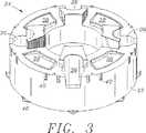
図3は、本発明の特徴を有するサンプルカルーセルの斜視図である。
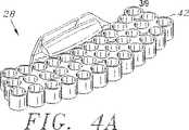
図4Aは、本発明の特徴を有する希釈セクションの斜視図である。
図4Bは、図4Aの希釈セクションの平面図である。
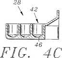
図4Cは、線4C−4Cに沿って切った図4Bに示す希釈セクションの側断面図である。
図4Dは、線4A−4Cに示す希釈容器の底面図である。
図5Aは、本発明で使用する反応キュベットモジュールの斜視図である。
図5Bは、図5Aに示す反応キュベットモジュールの側断面図である。
図6Aは、本発明の特徴を有するサンプル・プローブ・アーム・アセンブリの斜視図である。
図6Bは、図6Aに示すサンプル・プローブ・アーム・アセンブリの切り欠き図である。
図6Cは、本発明に有用なサンプル攪拌棒の正面図である。
図6Dは、図6Cに示すサンプル攪拌棒の側面図である。
図7Aは、本発明の特徴を有する試薬プローブ・アーム・アセンブリの斜視図である。
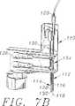
図7Bは、図7Aに示す試薬プローブ・アーム・アセンブリの切り欠き図である。
図7Cは、本発明に有用な試薬攪拌棒の正面図である。
図7Dは、図7Cに示す試薬攪拌棒の側面図である。
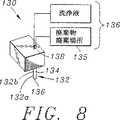
図8は、本発明に有用なキュベット洗浄ステーションの斜視図である。
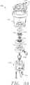
図9Aは、本発明の特徴を有する廃棄物トラップアセンブリの分解図である。
図9Bは、図9Aに示す完全に組み立てられた廃棄物トラップアセンブリの断面図である。
図9Cは、図9Aおよび図9Bに示す廃棄物トラップアセンブリに有用な弁の側断面図の詳細図である。
図9Dは、図9A−9Cに示す廃棄物トラップアセンブリに有用なフレキシブルディスクの平面図である。
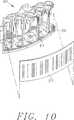
図10は、本発明の特徴を有するサンプル容器ラックの斜視図である。
発明の詳細な説明
次の説明は、本発明の詳細な1の実施例およびいくつかの変形例を示す。しかし、本発明は、これらの特定の実施例に制限するものとして解釈すべきではない。当業者は、同様に他の多数の実施例を認識するであろう。本発明の完全な範囲の定義は、添付した請求の範囲に記載されている。
図1および図2は、本発明の特徴を有する自動分析装置10を示す。この機器10は、本体12と、サンプルステーション14と、試薬ステーション16と、ランダムアクセス分析ステーション18とを有する。
本体12は、概ね分析装置10で使用される種々の操作部品のハウジングを提供するキャビネットである。本体12は、通常、軽量シートスチールのような軽量金属からつくられている。本体12は、機器10の操作部品を完全に包囲するキャノピー(図示せず)を有する。
サンプルステーション14は、複数のサンプル容器20を保持する寸法および大きさである。サンプルステーション14は、少なくとも1個のサンプル抽出場所を有する。
サンプルステーション14は、図3に示すような回転サンプルカルーセル24を有することが好ましい。通常、サンプルカルーセル24は、軽量金属または成形プラスティックから作られる。好ましくは、サンプルカルーセル24は、複数のサンプル容器20と、1個以上の希釈容器26と、複数の希釈セクション28とを保持する寸法および大きさである。
図面に示す実施例において、サンプルカルーセル24は、サンプルカルーセル24の外壁32にサンプル容器ラック30を保持するカルーセル保持アセンブリ40を有する。このような保持アセンブリ40は、図面に示した実施例で示したようなスロットである。
好ましくは、サンプル容器ラック30は、サンプル容器ラック30の前方部分41にバーコード情報を表示するカード37を保持するサンプル容器ラック保持アセンブリ39を有する。このようなサンプル容器ラック保持アセンブリ39は、図10に示す実施例における弾性クリップである。しかし、クランプ、クリップ、プロング、スナップ、ボタン、フックおよびループファスナ、ピン等を含むバーコード37をサンプル容器ラック30の前方部分41に取り付ける多数の他の方法も、同様に使用することができる。サンプル容器ラック保持アセンブリ39は、操作者がサンプル容器ラック30の前方部分41からバーコードカード37を迅速にかつ容易に取り付け、取り外しすることができることが好ましく、道具を使用しない場合は最も好ましい。
この実施例において、各サンプル容器ラック30はほぼ垂直の位置に9個の各々のサンプル容器20を収容している。
図3に示すサンプルカルーセル24は、4個の希釈容器保持場所36と4個の希釈セクション保持場所38とを有する。各希釈セクション28は、図4A−4Cに示すような複数の希釈カップ42を有する。通常、各希釈セクション28は、成形プラスティックからつくられる。好ましくは、各希釈セクション28は、洗浄を容易にするために簡単に設置され、サンプルのカルーセル24から除去される。また、希釈セクション28は、道具を使用することなく、サンプルカルーセル24に対して容易にかつ迅速に設定され、取り外し可能であることが好ましい。図に示す実施例は、希釈セクション28が希釈セクション保持場所38にスナップ適合することができるような弾性ノード44を有する。
各希釈カップ42は、約0.01と約1.0mlとの間の液体を保持する。図4Cに示すように、各希釈カップ42は、希釈カップの狭い窪み46を形成するために底部が先細になっており、希釈カップ42内の少量の液体が狭い窪みで液だまりになり、希釈カップ42から容易に抽出ことができる。各希釈カップの狭い窪み46は、通常、約10μlと約100μlとの間で保持することができる。この特徴は、試薬の廃棄量を最小にし、希釈カップ42が疎水性であるプラスティック材料からつくられる場合に特に重要である。このような場合において、希釈カップ42内の少量の液体が、液だまりになる代わりに液滴になる傾向があり、液体を希釈カップ42から抽出することが困難になる。
サンプルカルーセル24に配置された各サンプル容器20が1個のサンプル抽出場所22の下に配置されたり、そこから離れるように移動することができるように、サンプルカルーセル24は回転モータ(図示せず)によって可動である。
好ましくは、サンプルステーション14は、サンプルステーション14内のサンプル容器20、および/またはサンプル容器ラック30の前方部分41上に配置されたバーコードカード37上のバーコード情報を読むサンプルステーション・バーコード・リーダ47を更に有する。
試薬ステーション16は、複数の試薬容器48を保持する寸法および大きさであり、少なくとも1個の試薬抽出場所50を有する。本発明の機器で使用可能な、特に有用な試薬容器48は、「試薬カートリッジ」と題された米国特許出願に詳細に説明されている。これは、本願と同時に出願され、全体を本明細書に引用して援用する。試薬ステーション16は、試薬ステーション16内に配置された個々の試薬容器48が試薬抽出場所50に向かって、またはそこから離れるように交互に移動可能なように本体内で可動である。
サンプルステーション14と同様に、試薬ステーション16は、通常、軽量の金属または成形されたプラスティックからつくられた、回転可能な試薬カルーセル52を有することが好ましい。試薬カルーセル52は、試薬ステーションモータ(図示せず)によって回転される。
好ましくは、試薬ステーション16は、例えば約15℃まで冷蔵される。このように冷蔵することは、試薬の寿命を保ち、試薬の蒸発を最小限にする。
好ましくは、試薬ステーション16は、試薬ステーション16内の試薬容器20および/または試薬カルーセル24の外側上のバーコード情報を読む試薬ステーション・バーコード・リーダ53を更に有する。
ランダムアクセス分析ステーション18は、比濁計および濁度計の技術分野で通常よく知られているタイプの複数の反応キュベット54を保持する寸法および大きさである。ランダムアクセス分析ステーション18は、少なくとも1個のキュベット混合場所56と、1個のランダムアクセス分析ステーション分析場所58およびキュベット洗浄場所60を有する。
サンプルステーション14および試薬ステーション16と同様、ランダムアクセス分析ステーション18は、ランダムアクセス分析ステーションモータ(図示せず)によって回転される回転可能なカルーセル62を有することが好ましい。
図に示す実施例において、反応キュベット54は、各々が3個のキュベット54を含むキュベットモジュール64内に配置されている。キュベットモジュール64は、図5Aおよび図5に示されている。各キュベットモジュール64は、ランダムアクセス分析ステーションカルーセル62への堅固な固定を容易にするプロング66を有する。高価な試薬のコストを最小限にするために、キュベット54を、実際に可能な程度に小さく製作することが重要である。
多くの応用において、約37℃のような固定された上昇温度でランダムアクセス分析ステーション18が作動可能であることが好ましい。これを達成するために、ランダムアクセス分析ステーション18は、ランダムアクセス分析ステーション18を通して加熱空気を上方に循環する手段を有することが好ましい。
さらに、ランダムアクセス分析ステーション18は、ランダムアクセス分析ステーション分析器68を備え、この分析器68は、ランダムアクセス分析ステーション18内のキュベット54内に配置されたサンプルの少なくとも1つのパラメータを決定するために、ランダムアクセス分析ステーション分析場所58に接近して配置されている。好ましい実施例において、ランダムアクセス分析器68は、比濁計および濁度計との組み合わせである。このような組み合わせは、この技術分野でよく知られている。通常の、比濁計および濁度計の組み合わせの詳細な説明は、例えば、米国特許第5,296,195号に説明されており、全体として本明細書に引用して援用する。本発明の分析装置に有用な比濁計および濁度計の特に有用な組み合わせは、「比濁計および濁度計の組み合わせ」と題された米国特許出願に説明されており、これは、本明細書とともに出願され、全体として本明細書に引用して援用する。
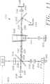
通常の比濁計および濁度計の組み合わせにおいて、ランダムアクセス分析場所58に配置されたキュベット54を通る第1の光ビームを第1の光レセプタ72に向ける第1の光源70があり、この光源70は、ランダムアクセス分析ステーション分析場所58に接近して配置されている。好ましい実施例において、この第1の光源70は、約600nmと約850nmとの間の波長で光を放出する可視ダイオードレーザである。好ましくは、第2の光源74も、ランダムアクセス分析場所58に配置されたキュベット54を通して、第2の光ビームを第2の光レセプタ76に向けるために、ランダムアクセス分析ステーション分析場所58の近傍に配置される。好ましい実施例において、この第2の光源74は、約850nmと約1050nmとの間の波長で光を放射することができる光放出ダイオードである。第1および第2の光レセプタ72および76は、第1および第2の光ビーム70および74がキュベット54を通して放射されるとき、散乱する光の量を測定する。図1に示す実施例において、第1の光レセプタ72は、第1の光ビームに対して90°の角度で散乱した光の量を測定するために、反応キュベット54の下に配置されている。この技術分野の当業者によく知られているように、このような光の散乱は、キュベット54内の1個以上の特定のパラメータと正確に関連づけることができる。
好ましくは、ランダムアクセス分析ステーション18は、さらに、内蔵制御サンプル78を有する。このような内蔵制御サンプル78は、機器10の正常な作動中に、ランダムアクセス分析ステーション分析器68を自動的に調整するようにユーザが装置にプログラムすることができる。この特徴は、従来技術の同様な装置に対して、精度および信頼性を最大限に向上させる。また、この特徴は、装置10を周期的に停止してランダムアクセス分析ステーション分析器68を調整する必要性をなくすことによって、スループットを増大する。本発明に使用可能な、特に有用な内蔵制御サンプルは、「非液体散乱基準」と題された米国特許出願に詳細に説明されており、これは本願と同時に出願され、全体として本明細書に引用して援用する。
本発明の分析装置10は、図6A−6Dに示すような、サンプル・プローブ・アーム・アセンブリ80を更に有する。このサンプル・プローブ・アーム・アセンブリ80は、サンプル・プローブ・アーム82と、中空のサンプルプローブ84と、回転可能なサンプル攪拌棒86とを有する。サンプルプローブ84は、内部チャンバ88と、開放した下端90と、開放した上端91とを有する。サンプルプローブ圧力変更アセンブリ92は、内部チャンバに圧力付加または真空操作を交互に行うために提供される。好ましくは、圧力変更アセンブリ92はシリンジ94を含む。
サンプルプローブ84は、サンプル・プローブ・アーム82に概ね垂直方向に配置され、下方のサンプルプローブ位置と上方サンプルプローブ位置との間でサンプル・プローブ・モータ96によって可動である。
サンプル攪拌棒86は、下端98と、上端100と、攪拌棒パドル102とを有する。また、攪拌棒86は、サンプル・プローブ・アーム82にほぼ垂直方向に配置されている。また、サンプル攪拌棒86は、下方のサンプル攪拌棒位置と上方のサンプル攪拌棒位置との間でサンプル攪拌棒モータ104によって可動である。サンプル攪拌棒は、サンプル攪拌棒回転モータ105によって作動的に回転される。
好ましくは、サンプル攪拌棒86の昇降は、サンプルプローブ84の昇降とは独立している。このことにより、プローブ84が昇降すると同時に、攪拌棒86を昇降させることのみが可能な従来技術の重要な同様の装置に対して、速度を高め、フレキシブル性を提供する。
好ましくは、サンプル攪拌棒86およびサンプル・プローブ・アーム84は、ラックおよびピニオンアセンブリ106を使用して昇降される。このようなラックおよびピニオンアセンブリ106は、以下にすぐに説明するように、対応する下端90および98が非常に接近するように互いに十分接近して、サンプルプローブ84および試薬プローブ86を取り付けることができる。
サンプルプローブ84およびサンプル攪拌棒86は、互いにわずかに傾斜してサンプル・プローブ・アーム82内に配置される。好ましくは、この角度αは、約2.4°と約2.6°との間である。サンプルプローブ84とサンプル攪拌棒86とは、互いに他の一方に向けて傾斜しており、サンプルプローブ84とサンプル攪拌棒86がそれらの対応する下方の位置にあるとき、サンプルプローブ84の下端90とサンプル攪拌棒の下端98との間の距離は、約1.7mmと約5.3mmとの間、さらに好ましくは、約1.7mmと約3.5mmとの間、最も好ましくは約1.7mmと約3mmとの間である。それらの各下方の位置90および98で互いに非常に接近するように、サンプルプローブ84とサンプル攪拌棒86とを構成することによって、従来技術の分析装置に使用されるものよりさらに小さい反応キュベット54内で有効にサンプルプローブ84とサンプル攪拌棒86とを使用することができる。このような小さい反応キュベット54を使用することで、操作者は著しく試薬を節減することができる。更に、操作者は非常に少量のサンプルで臨床的分析を行うことができる。
さらに本発明の装置は、図7A−7Dに示すような試薬プローブ・アーム・アセンブリ108を有する。試薬プローブ・アーム・アセンブリ108は、試薬プローブアーム110と、中空の試薬プローブ112と、回転可能な試薬攪拌棒114とを有する。試薬プローブ112は、内部チャンバ116と、開放した下端118と、開放した上端120とを有する。内部チャンバ116上に圧力付加または真空操作を交互に行うために、試薬圧力変更アセンブリ122が提供される。好ましくは、圧力変更アセンブリはシリンジ124を有する。
試薬プローブ112は、試薬プローブアーム110にほぼ垂直方向に配置され、下方の試薬プローブ位置と上方の試薬プローブ位置との間で試薬プローブモータ126によって可動である。
試薬攪拌棒114は、下端128と、上端130と、攪拌棒パドル132とを有する。また、試薬攪拌棒114は、試薬プローブアーム110にほぼ垂直方向に配置され、下方の試薬攪拌棒位置と上方の試薬攪拌棒位置との間で試薬攪拌棒モータ132によって可動である。サンプルプローブ84とサンプル攪拌棒86に関する場合のように、試薬攪拌棒114の昇降は、試薬プローブ112の昇降とは独立していることが好ましい。
試薬攪拌棒114と試薬プローブ112はラックおよびピニオンアセンブリ134を使用して昇降される。このようなラックおよびピニオンアセンブリ134は、以下に詳細に説明するように、それらの下端118および128で非常に接近するために、試薬プローブ112および試薬攪拌棒114を互いに十分接近して取り付けることができる。
サンプルプローブ84およびサンプル攪拌棒86と同様に、試薬プローブ112および試薬攪拌棒114は、互いにわずかに傾斜するように試薬プローブアーム110内に配置される。好ましくは、この角度βは、約2.4°と約2.6°との間である。試薬プローブ112および試薬攪拌棒114は、サンプルプローブ84およびサンプル攪拌棒86が互いに他の一方に向けて傾斜しているのと同じ理由で、互いに他の一方に向けて傾斜している。すなわち、約1.7mmと約5.3mmとの間、さらに好ましくは、約1.7mmと約3.5mmとの間、最も好ましくは、約1.7mmと約3mmとの間の距離まで試薬プローブ112と試薬攪拌棒114の下端118および128とが集中する。試薬プローブ112および試薬攪拌棒114の下端118および128が非常に接近していることによって、非常に小さい反応キュベット54の使用が可能となる。
好ましくは、サンプル・プローブ・アーム82と試薬プローブアーム108の双方は、液体のレベルに関して、プローブ84,112および/または攪拌棒86,114の上昇を決定するレベルコントローラ(図示せず)を有する。
本発明の装置10は、さらに、前記本体に固定されたキュベット洗浄ステーション130を有する。キュベット洗浄ステーション130は、内部チャンバ134、開放した下端136および開放した上端138を有する少なくとも1つの中空のキュベット洗浄ステーションプローブ132を備える。キュベット洗浄ステーション130は、キュベット洗浄ステーションプローブ132がキュベット洗浄場所60のすぐ上になるように配置される。
キュベット洗浄ステーションプローブ132は、下方のキュベット洗浄ステーションプローブ位置と上方のキュベット洗浄ステーションプローブ位置との間のキュベット洗浄ステーションモータ(図示せず)によって可動である。
図8に示す実施例において、キュベット洗浄ステーションプローブ132は、2つの同心円的に配置されたキュベット洗浄ステーションプローブ132aおよび132bを有する。1個のプローブ132がキュベットの内容物を空け、このような内容物を適当な廃棄場所135に移送するために使用される。他のプローブ132は、洗浄溶液をキュベットに提供するために使用される。
さらに本発明の装置は、(1)キュベット洗浄場所60に配置されたキュベット54を洗浄するために、洗浄液体源からキュベット洗浄ステーションプローブ132に加圧洗浄液体を、または、(2)分析場所60に配置されたキュベット54から廃液を除去し、このような廃液を適当な廃棄場所135に移送するためにキュベット洗浄ステーションプローブ132の内部チャンバ134に負圧を交互に提供するキュベット洗浄ステーションプローブ供給および廃棄アセンブリ136を備えている。
好ましい洗浄ステーションプローブ供給および廃棄アセンブリ136は、図9A−9Dに示す廃棄物トラップアセンブリ138を有する。廃棄物トラップアセンブリ138は、廃棄物トラップ貯蔵部140と、廃棄物トラップ貯蔵部140の下に配置された廃棄物コレクタボウル142とを有する。垂直方向に配置されたコネクタ導管144は、廃棄物コレクタボウル142に流体連通して、廃棄物トラップ貯蔵部140を接続する。コネクタ導管144は、最上端のリップ146を有し、その上に廃棄物トラップ貯蔵部140内で収集された廃液が廃棄物コレクタボウル142にこぼれる。コネクタ導管144は、コネクタ導管チェック弁を有し、コネクタ導管チェック弁148は、コネクタ導管144内の液体および圧縮空気の上方への流れが廃棄物コレクタボウル142から廃棄物トラップ貯蔵部140に流れることを防止する。
廃棄物トラップ貯蔵部140は、廃棄物トラップ貯蔵部140の上方部分に、キュベット洗浄ステーション130からの廃液を受ける入口ポート150を有する。廃棄物コレクタボウル142は、廃棄物コレクタボウル142の底部に出口ポート152を有し、出口ポート152は廃棄物コレクタボウル142内の液体をドレン導管154を介して適当な廃棄物廃棄設備に排出する。ドレン導管154は、ドレン導管154を介して廃棄物コレクタボウル142に液体が逆流することを防止するドレン導管チェック弁156を有する。
廃棄物コレクタボウル142内の液体のレベルを検出し、そのレベルに対応したレベルセンサ信号を放出するレベルセンサ158が廃棄物コレクタボウル142内に配置される。操作において、廃棄物トラップ貯蔵部140は、真空源に作動的に接続される。また、廃棄物コレクタボウル142は、スイッチ160を介して、真空源と圧縮空気源とに作動的に接続される。
さらに廃棄物トラップアセンブリ138は、(i)廃棄物コレクタボウル142内の液体レベルが所定の設定点以下であるとき、真空操作が廃棄物コレクタボウル142に行われ、廃棄物トラップ貯蔵部140から廃棄を吸引し、(ii)廃棄物コレクタボウル142内の液体レベルが所定の設定点であるとき、圧力が廃棄物コレクタボウル142に加えられ、廃棄物コレクタボウル142内の廃液をドレン導管154に引き下げるような方法で、レベルセンサからのレベルセンサ158信号を受け、廃棄物コレクタボウルに真空操作または圧力付加を行うことを制御する信号を用いる廃棄物トラップコントローラ(図示せず)を有する。
好ましくは、廃棄物トラップ・アセンブリ・コネクタ導管チェック弁148は、入口導管162と、入口導管162に配置され、それとともに緊密に液体連通された弁座164と、弁座164の下に配置され、それとともに緊密に液体連通する出口導管166と、弁座164内にゆるく配置されたプラグ168とを有し、(1)前記入口導管内の圧力が出口導管166内の圧力以上であるとき、プラグ168は、入口導管162内の廃液が出口導管166に重力で移動することができるように弁座164に対してきつく保持されず、(2)入口導管162内の圧力が出口導管166内の圧力未満であるとき、プラグ168は、入口導管162内の廃液が出口導管166に重力で移動することを防止し、出口導管166内の圧縮空気が入口導管164を通って廃棄物トラップ貯蔵部140に流れることを防止するように弁座に対してきつく保持される。
好ましくは、プラグ168は、図に示すようにフレキシブルディスクである。前記フレキシブルディスクは、入口導管162から分かれ出る少なくとも1個の中央開口部170を有する。
好ましくは、廃棄物トラップアセンブリ138は、(a)廃棄物トラップ貯蔵部140内に配置された真空源入口ポート172を有し、この真空源入口ポート172は、真空源に接続可能であり、(b)通常開放したポート178と、通常閉鎖したポート180と、共通のポート176を有する三方弁174と、(c)共通のポート176と廃棄物コレクタボウル142との間に緊密な液体連通するように接続された第1の圧力源導管181と、(d)通常開放したポート178と廃棄物トラップ貯蔵部140との間で緊密に液体連通するように接続された第2の圧力源導管182と、(e)通常閉鎖したポート180と圧縮空気源との間で緊密な液体連通するように接続する第3の圧力源導管184とを有する。
この廃棄物トラップアセンブリ138は、従来技術の廃棄物トラップアセンブリに対して著しい利点を提供する。本発明の廃棄物トラップアセンブリ138は、1個の真空貯蔵室140と1個の真空ポンプのみを必要とする。さらに、洗浄サイクルは、廃液を吸引するために中断される必要はない。また、従来技術の装置で概ね必要とされるように、外部の廃棄物ポンプを必要としない。この理由は、本発明の廃棄物トラップアセンブリ138はアセンブリから廃棄物を除くために、空気圧に依存するからである。いくつかの従来技術の装置も、圧縮空気を使用して廃棄物トラップアセンブリから廃棄物を除く。しかし、このような装置は、真空操作を浪費する。なぜならば、三方弁の貯蔵部のレベル信号が切り替わる毎に、貯蔵部の吸引した内容物全体が、ポンプに廃棄物を押し出すために圧縮空気と交換されるからである。これは、全体を真空にするためには16秒以上を要するため、装置の動作を著しく低下させる。さらに、比較的大きな真空ポンプが必要である。
好ましくは、さらに本発明の分析装置10は、モータ、分析器およびバーコードリーダの動作を制御するコントローラ186を有する。好ましくは、コントローラ186は、デジタルコンピュータを有し、このコンピュータは、分析器68から結果を受け、この結果を有効なフォーマットで操作者に報告するようにもプログラムされている。
操作において、分析装置の好ましい実施例の操作者は、試薬ステーション16にキットから予め混合された試薬を付加する。このキットは、1個以上の試薬容器48を有し、この試薬容器48は、予め混合された試薬と、このキット内の試薬に関してバーコード情報を備えたバーコードカードとを有する。
試薬容器48を試薬ステーション16に配置した後、操作者はサンプル容器ラック保持アセンブリ40を使用して、サンプル容器ラック30の前方部分41の試薬キットからバーコードカード37を配置する。次に、操作者はバーコードカード37に含まれるバーコード情報をコントローラに読み込ませるようにサンプル・ステーション・バーコード・リーダ47に指示し、サンプル容器30からバーコードカード37を取り外す。
次に、操作者は分析すべきサンプルを含むサンプル容器20をサンプルカルーセル24に配置する。サンプル容器20は、サンプル容器ラック30に入れられ、サンプル容器ラック30は、サンプルカルーセル24の外周縁に取り付けられている。サンプルの各々の識別に関するバーコード情報およびサンプルの各々における分析を含むラベルが各サンプル容器20に取り付けられる。更に、サンプルカルーセル24に希釈容器26を配置して、サンプルカルーセル24に清浄な希釈セクション28を配置し、つぎのステップを自動的に実行する装置10を作動させる。
サンプルカルーセル24が回転され、しばしば停止する。容器20がサンプル・ステーション・バーコード・リーダ47の前方に配置されるときはいつでも、バーコードリーダ47は、サンプル容器20のラベルのバーコード情報を読み、コントローラ186に情報を送る。
サンプル・プローブ・アーム82は、サンプル・ステーション・プローブ84をサンプル抽出場所22のすぐ上の場所に移動させる。サンプルプローブ84は、サンプルプローブ84がサンプル抽出場所22に配置されたサンプル容器20内のサンプルの表面の下にある事をサンプル・プローブ・レベル・コントローラが検出するまで、上方のプローブ位置から下降される。
次に、サンプルプローブ圧力変更アセンブリ92はサンプルプローブ内部チャンバ88を吸引して真空にする。同様にこれは、サンプル容器20内のサンプルをサンプルプローブ内部チャンバ88に吸引する。このサンプルプローブ84は、上方の位置まで上昇され、サンプル・プローブ・アーム82は、1個の希釈カップ42の上の位置まで回転する。サンプルプローブ84は、希釈カップ42に再び下降され、サンプルプローブ圧力変更アセンブリ92は、サンプルプローブ84内のサンプルを希釈カップ42に排出する。
サンプル・プローブ・アーム82は、サンプルステーション14内の1個の希釈容器26のすぐ上の位置までサンプルプローブ84を回転させる。サンプルプローブ84は、上方の位置から、サンプル・プローブ・レベル・コントローラによって検出される希釈容器26内の希釈液の表面の下の位置まで下降される。圧力変更アセンブリ92は、サンプルプローブ内部チャンバ88内に吸引して真空にし、希釈液はサンプルプローブ84に吸引される。サンプルプローブ84は、上方の位置まで上昇し、サンプルアームは1個の希釈カップ42のすぐ上の位置までサンプルプローブ84を回転させる。サンプルプローブ84は、希釈カップ42まで下降し、圧力変更アセンブリ92は、希釈液をサンプルプローブ84から希釈カップ42に押し出す。
サンプル攪拌棒86は、希釈カップ42まで下降し、サンプル攪拌棒回転モータ105は、サンプルと希釈液とを混合するように作動する。
次に、サンプルプローブ84は、再び希釈カップ42に下降し、希釈液−サンプル混合物がサンプルプローブ84に吸引される。このサンプル・プローブ・アーム82は、キュベット混合場所56におけるキュベット54のすぐ上の位置までサンプルプローブ84を回転させる。その後、サンプルプローブ84はキュベット54に下降し、希釈液−サンプル混合物は、サンプルプローブ圧力変更アセンブリ92によってサンプルプローブ84からキュベット54に押し出される。
これらのステップの前後において、コントローラ186は、試薬プローブアーム110を試薬抽出場所22内の適当な試薬容器48のすぐ上で作動させ、試薬プローブ112は、試薬容器48まで下降し、一定量の試薬が試薬プローブ112に吸引される。試薬プローブ112はその上方の位置まで上昇し、試薬アーム110は、キュベット混合場所56におけるキュベット54上で試薬プローブ112を回転する。試薬プローブ112は、キュベット54に下降し、試薬はキュベット54に排出される。
この点において、サンプル攪拌棒86(または、この時点でキュベット混合場所のすぐ上にあることに依存する試薬攪拌棒114)がキュベット54に下降し、前記回転モータが攪拌棒パドル102で試薬−サンプル混合物を攪拌する。混合の後、攪拌棒86は上方の位置に後退する。
コントローラ186は、ランダムアクセス分析ステーションカルーセル62に、ランダムアクセス分析ステーション分析場所58を越えて試薬−サンプル混合物を有するキュベット54を回転させる。この分析場所58において、ランダムアクセス分析ステーション分析器68はキュベット54の内容物を分析し、コントローラ186にこの情報を伝達する。好ましくは、コントローラ186は種々の場合でランダムアクセス分析ステーション分析場所58をキュベット54が通過可能にし、各々の場合において内容物を分析するように分析器68に指示する。したがって、同じ試薬−サンプル混合物の種々の分析を行うことによって、コントローラ186による最終的に報告可能な結果は、性質上非常に正確である。
キュベット54の内容物を分析した後、ランダムアクセス分析ステーションカルーセル62は、キュベット54がキュベット洗浄場所60のすぐ下になるように回転される。キュベット洗浄場所60において、キュベット洗浄ステーションプローブ132は、キュベット54に下降し、キュベット54の内容物は、キュベット54から引き出され、キュベット洗浄プローブ供給源および廃棄アセンブリ136を使用して適当な廃棄場所まで送られる。キュベット54は圧縮洗浄液体で洗浄され、この液体はキュベット洗浄プローブ供給源および廃棄アセンブリ136を使用して適当な廃棄場所まで送られる。キュベット54は洗浄されて他の分析操作のために準備される。
コントローラ186は、分析処理の種々の段階で多数の反応キュベット54の経過を追うようにプログラムされることが好ましい。コントローラ186は、上記のように、ランダムアクセス分析ステーションカルーセル62を高速で回転し、1個以上の種々の操作において、種々のキュベット場所まで多数の作動キュベット54を移動する。この方法において、分析装置10は、非常に短い時間において多数の分析を実行することができる。
機器の通常の動作中において、コントローラ186はランダムアクセス分析ステーション分析器68に内蔵制御サンプル78の内容物を周期的に分析させる。この分析結果が分析器68が調整されていないことを示唆する場合には、分析器68は自動的に再調整される。
本発明は、スループット、精度および信頼性を向上しながら試薬のコストおよび操作の費用を低減することによって、従来技術に対して著しい改良を提供する。
本発明をある好ましい実施例を参照して詳細に説明したが、他の実施例も可能である。したがって、請求の範囲の精神および範囲は、ここに含まれる好ましい実施例の説明に制限されるべきではない。Field of Invention
The present invention relates to the field of automated clinical chemistry analyzers, and more particularly to a compact automated chemistry analyzer using a nephelometer.
Background of the Invention
A number of different automatic clinical chemistry analyzers (automatic clinical chemistry analyzers) are known in the art. Such analyzers range from simple and primarily manual instruments to very complex, almost fully automated instruments. Each analyzer has its own performance characteristics related to the number of different tests that the analyzer can perform (menu) and the number of samples that the analyzer can process at a given time (throughput).
Many of today's automated analyzers are sophisticated and efficient, but some problems continue to exist. The first problem is the throughput capacity. This means that millions of dollars of expensive pharmaceutical resources are saved every second that can be saved in the analysis time of a single sample. Therefore, continuous pressure is applied to the manufacturer of the analyzer to increase throughput. Prior art automated analyzers are very fast, but not fast enough.
Another problem with the prior art is operational costs. The most automated analyzers of the prior art use relatively large reaction vessels (cuvettes) that require large amounts of expensive reagent material.
Yet another problem with the prior art is the amount of time that an operator must spend to enter data and instructions into the analyzer. This reduces throughput and results in excessive personnel costs.
Another issue with throughput is the need for a prior art analyzer that uses a nephelometer analyzer that periodically interrupts operation to tune the nephelometer.
Finally, there is a problem regarding the throughput of the vacuum drain device used in the automatic analyzer of the prior art. Such vacuum drain devices are generally uneconomical for the use of vacuum operations. Such waste causes a great deal of vacuum operation and reduces the throughput of the analyzer.
Therefore, there is a need for an automated clinical chemistry analyzer that has greater throughput, requires fewer operating personnel, and is more reliable and effective than prior art analyzer modules.
Summary of the Invention
The present invention satisfies these needs. The present invention
(A) a main body;
(B) a sample station disposed within the body and actuated by a motor, wherein the sample station holds a plurality of sample containers and is sized and sized to include a sample extraction location; A sample station that is movable within the body so that when held, individual sample containers can be moved alternately toward or away from the sample extraction location;
(C) a reagent station disposed within the main body and driven by a motor, the reagent station holding a plurality of reagent containers and having a reagent extraction location, the reagent station having a plurality of reagent containers A reagent station that is moveable within the body so that when held, individual reagent containers can be moved alternately toward or away from the reagent extraction location;
(D) a random access analysis station disposed within the body and driven by a motor, the size and size holding a plurality of reaction cuvettes; cuvette mixing location, cuvette washing location, random access analysis station analysis A random access analysis station that determines a location, and at least one parameter of a sample located in the cuvette, having an analyzer placed close to the analysis location, the random access analysis station holding a plurality of cuvettes In doing so, individual cuvettes can be alternately moved toward or away from (1) the cuvette mixing location, (2) the cuvette washing location, and (3) the random access analysis station analysis location. Is movable within the main body. A random access analyzing station being driven by motor,
(E) a sample probe arm assembly mounted in the body, comprising: (1) a sample probe arm; and (2) a hollow sample probe having an internal chamber, an open lower end and an open upper end. And (3) an elongated rotatable sample stirring bar having a lower end and an upper end, the lower end of the sample stirring bar having a sample stirring bar paddle attached to the lower end of the sample stirring bar, and the sample probe And the sample agitation rods are in close proximity to each other and are arranged in a substantially vertical direction, the sample probe being movable vertically between a lower sample probe position and an upper sample probe position, The sample probe is located between the lower sample stirring bar position and the upper sample stirring bar position. Are independently movable, and the sample probe and the sample agitation bar are located when the sample probe is at the lower sample probe position and the sample agitation bar is at the lower sample agitation bar position. A first sample probe arm position where the sample probe is directly above the sample extraction location; and a second sample probe arm position where the sample probe is immediately above the cuvette mixing location. A sample probe arm assembly disposed within the sample probe arm assembly to be movable between
(F) a sample probe positioning motor that moves the sample probe between the lower sample probe position and the upper sample probe position;
(G) a sample stirring rod positioning motor that moves the sample stirring rod between the lower sample stirring rod position and the upper sample stirring rod position;
(H) a sample stirring rod rotating motor for rotating the sample stirring rod;
(I) a sample probe pressure changing assembly that alternately applies positive and negative pressures to the internal chamber of the sample probe;
(J) a reagent probe arm assembly attached to the body, comprising: (1) a reagent probe arm; (2) an internal chamber; a hollow reagent probe having an open lower end and an open upper end; 3) an elongated rotatable reagent stirring bar having a lower end and an upper end, and the lower end of the reagent stirring bar includes a reagent stirring bar paddle attached to the lower end of the reagent stirring bar, and the reagent probe and the reagent The stir bars are in close proximity to each other and arranged in a substantially vertical direction, the reagent probe is movable vertically between a lower reagent probe position and an upper reagent probe position, and the reagent stir bar is The reagent probe is movable independently between a lower reagent stirring bar position and an upper reagent stirring bar position. When the probe is in the lower reagent probe position and the reagent agitation bar is in the lower reagent agitation bar position, the reagent probe arm is a first reagent in which the reagent probe is immediately above the reagent extraction location. A reagent probe arm positioned within the reagent probe arm assembly such that the probe arm is movable between a probe arm position and a second reagent probe arm position immediately above the cuvette mixing location. An assembly;
(K) a reagent probe positioning motor for moving the reagent probe between the lower reagent probe position and the upper reagent probe position;
(L) a reagent stirring rod positioning motor for moving the reagent stirring rod between the lower reagent stirring rod position and the upper reagent stirring rod position;
(M) a reagent stirring rod rotating motor for rotating the reagent stirring rod;
(N) a reagent probe pressure changing assembly that alternately applies positive and negative pressure to the internal chamber of the reagent probe;
(O) a cuvette cleaning station attached to the body comprising a hollow cuvette cleaning station probe operated by at least one motor having an internal chamber, an open lower end, and an open upper end; A cuvette washing station arranged so that the probe is directly above the cuvette washing place;
(P) (1) Pressurized wash liquid from a wash liquid source to the cuvette wash station probe to wash a cuvette located in the random access analysis station at the cuvette wash place, or (2) the analysis place In order to remove waste liquid from the cuvette located in the random access analysis station, and to transfer such waste liquid to an appropriate disposal location, alternately send negative pressure to the internal chamber of the cuvette washing station probe. An apparatus is provided for determining at least one parameter of a liquid sample comprising a station probe source and a waste assembly.
Preferably, in each probe arm, the distance between the probe and the stirring bar at their lowest position is between about 1.7 mm and about 5.3 mm, more preferably about 1.7 mm and about Between 3.5 mm, most preferably between about 1.7 mm and 3 mm.
Preferably, in each probe arm, the probe and the stirring rod are movable in the vertical direction independently of each other.
Preferably, each probe and stir bar are attached to their probe arms by a rack and pinion assembly to raise and lower the probe and stir bar. This feature allows independent operation of the probe and stir bar (at their lowest position) while the lower ends of the probe and stir bar are very close to each other. This in turn allows the use of smaller reaction vessels that require a minimum amount of expensive reagents.
In a preferred embodiment, the sample station comprises a rotating sample carousel having an outer wall, the outer wall being provided with a holding assembly for holding a card displaying bar code information. This allows a barcode reader located within the device to read barcode information regarding the reagent containers used in the device.
In another preferred embodiment, the sample station has a plurality of dilution sections each having a plurality of dilution cups. This feature can minimize the use of expensive reagents by the device.
In yet another preferred embodiment, the cuvette cleaning probe source and waste assembly comprises: (a) a waste trap reservoir; and (b) a waste collector bowl disposed below the waste trap reservoir; (C) connecting the waste trap reservoir in fluid communication with the waste collector bowl and having an uppermost lip through which waste liquid in the waste trap reservoir can be spilled into the waste collector bowl A vertically disposed connector conduit; and (d) a connector conduit check valve that prevents liquid and compressed air in the connector conduit of the waste trap reservoir from flowing upwardly from the waste collector bowl; (E) an inlet port in the upper portion of the waste trap reservoir that receives waste liquid from the cuvette cleaning station probe; (F) an appropriate waste disposal facility via a drain conduit; and an outlet port at the bottom of the waste collector bowl for draining the liquid in the waste collector bowl; and (g) via the drain conduit. A drain conduit check valve disposed in the drain conduit for preventing liquid from flowing into the waste collector bowl; and (h) detecting a level of liquid in the waste collector bowl and a corresponding level sensor signal. (I) a switch assembly that alternately applies pressure or vacuum to the waste collector bowl, and (j) (i) the level of the liquid in the waste collector is a predetermined setting. A vacuum operation is performed on the waste collector bowl to aspirate the waste liquid from the waste trap reservoir, and (ii) in the waste collector When the liquid level of the liquid is at a predetermined set point, pressure is applied to the waste collector bowl and receives a level sensor signal from the level sensor to pull the liquid in the waste collector bowl down to the drain conduit. A waste trap assembly having a waste trap controller for controlling the switch assembly to allow vacuuming and pressure application to the waste collector bowl.
The present invention is also a method for analyzing a plurality of liquid samples using the apparatus described above.
The present invention further relates to a chemical test reagent kit for use in an automatic test instrument having an internal barcode reader. The kit has at least one container containing a reagent and a barcode card containing barcode information about the reagent. The bar code card is sized and sized to be read by an internal bar code reader of the automatic test equipment.
The present invention provides significant improvements over the prior art by increasing throughput, accuracy and reliability, as well as reducing reagent and operating costs.
Description of drawings
These and other features, aspects and advantages of the present invention will become better understood with reference to the following description, appended claims and accompanying drawings.
FIG. 1 is a schematic plan view of an automatic analyzer having features of the present invention.
FIG. 2 is a front view of an automatic analyzer having features of the present invention.
FIG. 3 is a perspective view of a sample carousel having features of the present invention.
FIG. 4A is a perspective view of a dilution section having features of the present invention.
FIG. 4B is a plan view of the dilution section of FIG. 4A.
4C is a cross-sectional side view of the dilution section shown in FIG. 4B taken along
FIG. 4D is a bottom view of the dilution container indicated by line 4A-4C.
FIG. 5A is a perspective view of a reaction cuvette module used in the present invention.
FIG. 5B is a cross-sectional side view of the reaction cuvette module shown in FIG. 5A.
FIG. 6A is a perspective view of a sample probe arm assembly having features of the present invention.
6B is a cutaway view of the sample probe arm assembly shown in FIG. 6A.
FIG. 6C is a front view of a sample stir bar useful in the present invention.
6D is a side view of the sample stirring rod shown in FIG. 6C.
FIG. 7A is a perspective view of a reagent probe arm assembly having features of the present invention.
FIG. 7B is a cutaway view of the reagent probe arm assembly shown in FIG. 7A.
FIG. 7C is a front view of a reagent stirring bar useful in the present invention.
FIG. 7D is a side view of the reagent stirring rod shown in FIG. 7C.
FIG. 8 is a perspective view of a cuvette cleaning station useful in the present invention.
FIG. 9A is an exploded view of a waste trap assembly having features of the present invention.
9B is a cross-sectional view of the fully assembled waste trap assembly shown in FIG. 9A.
FIG. 9C is a detailed side sectional view of a valve useful in the waste trap assembly shown in FIGS. 9A and 9B.
FIG. 9D is a top view of a flexible disk useful for the waste trap assembly shown in FIGS. 9A-9C.
FIG. 10 is a perspective view of a sample container rack having features of the present invention.
Detailed Description of the Invention
The following description shows one detailed embodiment of the invention and some variations. However, the invention should not be construed as limited to these particular embodiments. Those skilled in the art will recognize numerous other embodiments as well. The full scope of the invention is defined in the appended claims.
1 and 2 show an
The
The sample station 14 is sized and sized to hold a plurality of
The sample station 14 preferably has a
In the illustrated embodiment, the
Preferably, the
In this embodiment, each
The
Each
The
Preferably, the sample station 14 reads the barcode information on the
The
Similar to the sample station 14, the
Preferably, the
Preferably, the
Random
Similar to sample station 14 and
In the illustrated embodiment, the
In many applications, it is preferred that the random
In addition, the random
In a typical nephelometer and turbidimeter combination, there is a
Preferably, the random
The
The
The
Preferably, the raising and lowering of the
Preferably, the
The
The apparatus of the present invention further includes a reagent
The
The
Similar to the
Preferably, both the
The
The cuvette
In the embodiment shown in FIG. 8, cuvette cleaning
In addition, the apparatus of the present invention can either (1) apply a pressurized cleaning liquid from a cleaning liquid source to the cuvette
A preferred wash station probe supply and
The waste
A
Further, the waste trap assembly 138 (i) when the liquid level in the
Preferably, the waste trap assembly connector
Preferably, the
Preferably, the
This
Preferably, the
In operation, the operator of the preferred embodiment of the analyzer adds reagents premixed from the kit to the
After placing the reagent container 48 in the
Next, the operator places the
The
The
The sample probe
The
Next, the
Before and after these steps, the controller 186 activates the
At this point, the sample stir bar 86 (or the
The controller 186 causes the random access analysis station carousel 62 to rotate the
After analyzing the contents of the
Controller 186 is preferably programmed to keep track of
During normal operation of the instrument, the controller 186 causes the random access
The present invention provides a significant improvement over the prior art by reducing reagent costs and operating costs while increasing throughput, accuracy and reliability.
Although the present invention has been described in detail with reference to certain preferred embodiments, other embodiments are possible. Therefore, the spirit and scope of the claims should not be limited to the description of the preferred embodiments contained herein.
Claims (33)
Translated fromJapanese(b)前記本体内に配置されかつモータによって作動されるサンプルステーションであって、複数のサンプル容器を保持し、サンプル抽出場所を備える寸法と大きさであり、前記サンプルステーションが複数のサンプル容器を保持するとき、個々のサンプル容器がサンプル抽出場所に向かって、または前記抽出場所から離れるように交互に移動することができるように、前記本体内で可動であるサンプルステーションと、
(c)前記本体内に配置されかつモータで駆動される試薬ステーションであって、複数の試薬容器を保持し、試薬抽出場所を備える寸法と大きさであり、前記試薬ステーションが複数の試薬容器を保持するとき、個々の試薬容器が試薬抽出場所に向かって、または前記試薬抽出場所から離れるように交互に移動することができるように、前記本体内で可動である試薬ステーションと、
(d)前記本体内に配置されかつモータで駆動されるランダムアクセス分析ステーションであって、複数の反応キュベットを保持する寸法と大きさであり、キュベット混合場所、キュベット洗浄場所、ランダムアクセス分析ステーション分析場所、および前記キュベット内に配置されたサンプルの少なくとも1個のパラメータを決定するランダムアクセス分析ステーション分析場所に接近して配置された分析器を有し、前記ランダムアクセス分析ステーションが複数のキュベットを保持するとき、個々のキュベットが(1)キュベット混合場所、(2)キュベット洗浄場所、および(3)ランダムアクセス分析ステーション分析場所に向かって、またはそれらの場所から離れるように交互に移動することができるように前記本体内で可動であるモータで駆動されるランダムアクセス分析ステーションと、
(e)前記本体に取り付けられたサンプル・プローブ・アーム・アセンブリであって、(1)サンプル・プローブ・アームと、(2)内部チャンバ、開放した下端および開放した上端を有する中空のサンプルプローブと、(3)下端および上端を有する細長い回転可能なサンプル攪拌棒とを備え、前記サンプル攪拌棒の下端は、前記サンプル攪拌棒の下端に取り付けられたサンプル攪拌棒パドルを有し、前記サンプルプローブおよび前記サンプル攪拌棒は互いに緊密に接近して、ほぼ垂直方向に配置されており、前記サンプルプローブは、下方サンプルプローブ位置と上方サンプルプローブ位置との間で垂直方向に可動であり、前記サンプル攪拌棒は、下方のサンプル攪拌棒位置と上方のサンプル攪拌棒位置との間で前記サンプルプローブとは独立して可動であり、前記サンプルプローブおよび前記サンプル攪拌棒は、前記サンプルプローブが前記下方のサンプルプローブ位置にあり、前記サンプル攪拌棒が下方のサンプル攪拌棒位置にあるとき、前記サンプルプローブの下端が約1.7mmと約5.3mmとの間の距離だけ前記サンプル攪拌棒の下端から間隔を置くように、前記サンプル・プローブ・アーム・アセンブリ内に配置され、前記サンプル・プローブ・アームは、前記サンプルプローブがサンプル抽出場所のすぐ上にある第1のサンプル・プローブ・アーム位置と、前記サンプルプローブが前記キュベット混合場所のすぐ上にある第2のサンプル・プローブ・アーム位置との間で可動であるサンプル・プローブアーム・アセンブリと、
(f)前記第1のサンプル・プローブ・アーム位置と前記第2のサンプル・プローブ・アーム位置との間で前記サンプル・プローブ・アームを移動するサンプル・プローブ・アーム・モータと、
(g)前記下方サンプルプローブ位置と前記上方サンプルプローブ位置との間で前記サンプルプローブを移動するサンプルプローブ位置決めモータと、
(h)前記下方サンプル攪拌棒位置と前記上方サンプル攪拌棒位置との間で前記サンプル攪拌棒を移動するサンプル攪拌棒位置決めモータと、
(i)前記サンプル攪拌棒を回転するサンプル攪拌棒回転モータと、
(j)前記サンプルプローブの内部チャンバに正圧と負圧を交互に加えるサンプルプローブ圧力変更アセンブリと、
(k)前記本体に取り付けられた試薬プローブ・アーム・アセンブリであって、(1)試薬プローブアームと、(2)内部チャンバ、開放した下端および開放した上端を有する中空の試薬プローブと、(3)下端および上端を有する細長い回転可能な試薬攪拌棒とを有し、前記試薬攪拌棒の下端は、前記試薬攪拌棒の下端に取り付けられた試薬攪拌棒パドルを有し、前記試薬プローブおよび前記試薬攪拌棒は互いに緊密に接近して、ほぼ垂直方向に配置されており、前記試薬プローブは、下方試薬プローブ位置と上方試薬プローブ位置との間で垂直方向に可動であり、前記試薬攪拌棒は、下方の試薬攪拌棒位置と上方の試薬攪拌棒との間で前記試薬プローブとは独立して可動であり、前記試薬プローブおよび前記試薬攪拌棒は、前記試薬プローブが前記下方の試薬プローブ位置にあり、前記試薬攪拌棒が前記下方の試薬攪拌棒位置にあるとき、前記試薬プローブの下端が約1.7mmと約5.3mmとの間の距離だけ、前記試薬攪拌棒の下端から間隔を置くように前記試薬プローブ・アーム・アセンブリ内に配置され、前記試薬プローブアームは、前記試薬プローブが前記試薬抽出場所のすぐ上にある第1の試薬プローブアーム位置と、前記試薬プローブが前記キュベット混合場所のすぐ上にある第2の試薬プローブアーム位置との間で可動である試薬プローブ・アーム・アセンブリと、
(l)前記第1の試薬プローブアーム位置および前記第2の試薬プローブアーム位置との間で前記試薬プローブアームを移動する試薬プローブ・アーム・モータと、
(m)前記下方の試薬プローブ位置と前記上方の試薬プローブ位置との間で前記試薬プローブを移動する試薬プローブ位置決めモータと、
(n)前記下方の試薬攪拌棒位置と前記上方の試薬攪拌棒位置との間で前記試薬攪拌棒を移動する試薬攪拌棒位置決めモータと、
(o)前記試薬攪拌棒を回転する試薬攪拌棒回転モータと、
(p)前記試薬プローブの内部チャンバに正圧および負圧を交互に加える試薬プローブ圧力変更アセンブリと、
(q)前記本体に取り付けられたキュベット洗浄ステーションであって、内部チャンバ、開放した下端、および開放した上端を有する少なくとも1つの中空のキュベット洗浄ステーションプローブを有し、前記キュベット洗浄ステーションプローブが前記キュベット洗浄場所のすぐ上になるように配置されるキュベット洗浄ステーションと、
(r)前記下方キュベット洗浄ステーションプローブ位置と前記上方キュベット洗浄ステーションプローブ位置との間で前記キュベット洗浄ステーションプローブを移動するキュベット洗浄ステーションプローブ位置決めモータと、
(s)(1)前記キュベット洗浄場所で前記ランダムアクセス分析ステーション内に配置されたキュベットを洗浄するために前記キュベット洗浄ステーションプローブに洗浄液体源から加圧洗浄液体を、または、(2)分析場所で前記ランダムアクセス分析ステーション内に配置されたキュベットから廃液を除去し、このような廃液を廃棄場所に移送するために、前記キュベット洗浄ステーションプローブの内部チャンバに負圧を交互に送るキュベット洗浄ステーションプローブ供給および廃棄アセンブリとを備える液体サンプルの少なくとも1つのパラメータを決定する装置。(A) a main body;
(B) a sample station disposed within the body and actuated by a motor, wherein the sample station holds a plurality of sample containers and is sized and sized to include a sample extraction location; A sample station that is movable within the body so that when held, individual sample containers can be moved alternately toward or away from the sample extraction location;
(C) a reagent station disposed within the main body and driven by a motor, the reagent station holding a plurality of reagent containers and having a reagent extraction location, the reagent station having a plurality of reagent containers A reagent station that is moveable within the body so that when held, individual reagent containers can be moved alternately toward or away from the reagent extraction location;
(D) a random access analysis station disposed within the body and driven by a motor, the size and size holding a plurality of reaction cuvettes; cuvette mixing location, cuvette washing location, random access analysis station analysis A random access analysis station that determines a location, and at least one parameter of a sample located in the cuvette, having an analyzer placed close to the analysis location, the random access analysis station holding a plurality of cuvettes In doing so, individual cuvettes can be moved alternately toward or away from (1) cuvette mixing location, (2) cuvette washing location, and (3) random access analysis station analysis location. Is movable in the body A random access analyzing station being driven by a motor,
(E) a sample probe arm assembly attached to said body, comprising: (1) a sample probe arm; and (2) a hollow sample probe having an internal chamber, an open lower end and an open upper end. (3) an elongated rotatable sample stirring bar having a lower end and an upper end, the lower end of the sample stirring bar having a sample stirring bar paddle attached to the lower end of the sample stirring bar, The sample agitation bars are in close proximity to each other and arranged in a substantially vertical direction, and the sample probe is movable vertically between a lower sample probe position and an upper sample probe position, the sample agitation bar Between the lower sample stir bar position and the upper sample stir bar position The sample probe and the sample stirring bar are independently movable, and the lower end of the sample probe when the sample probe is at the lower sample probe position and the sample stirring bar is at the lower sample stirring bar position. Is positioned within the sample probe arm assembly such that the sample probe arm is spaced from the lower end of the sample stir bar by a distance between about 1.7 mm and about 5.3 mm, Moveable between a first sample probe arm position where the sample probe is directly above the sample extraction location and a second sample probe arm position where the sample probe is immediately above the cuvette mixing location A sample probe arm assembly,
(F) a sample probe arm motor that moves the sample probe arm between the first sample probe arm position and the second sample probe arm position;
(G) a sample probe positioning motor that moves the sample probe between the lower sample probe position and the upper sample probe position;
(H) a sample stirring rod positioning motor that moves the sample stirring rod between the lower sample stirring rod position and the upper sample stirring rod position;
(I) a sample stirring rod rotating motor for rotating the sample stirring rod;
(J) a sample probe pressure changing assembly that alternately applies positive and negative pressures to the internal chamber of the sample probe;
(K) a reagent probe arm assembly attached to said body, comprising: (1) a reagent probe arm; (2) a hollow reagent probe having an internal chamber, an open lower end and an open upper end; ) An elongated rotatable reagent stirring bar having a lower end and an upper end, and the lower end of the reagent stirring bar has a reagent stirring bar paddle attached to the lower end of the reagent stirring bar, and the reagent probe and the reagent The stir bars are in close proximity to each other and arranged in a substantially vertical direction, the reagent probe is movable vertically between a lower reagent probe position and an upper reagent probe position, and the reagent stir bar is The reagent probe is movable independently of the position of the lower reagent stirring bar and the upper reagent stirring bar, and the reagent probe and the reagent stirring bar are connected to the reagent probe. When the reagent probe is in the lower reagent probe position and the reagent stirring rod is in the lower reagent stirring rod position, the lower end of the reagent probe is at a distance between about 1.7 mm and about 5.3 mm. Positioned within the reagent probe arm assembly spaced from the lower end of a reagent stir bar, the reagent probe arm having a first reagent probe arm position where the reagent probe is immediately above the reagent extraction location; A reagent probe arm assembly wherein the reagent probe is movable between a second reagent probe arm position immediately above the cuvette mixing location;
(L) a reagent probe arm motor for moving the reagent probe arm between the first reagent probe arm position and the second reagent probe arm position;
(M) a reagent probe positioning motor for moving the reagent probe between the lower reagent probe position and the upper reagent probe position;
(N) a reagent stirring rod positioning motor for moving the reagent stirring rod between the lower reagent stirring rod position and the upper reagent stirring rod position;
(O) a reagent stirring rod rotating motor for rotating the reagent stirring rod;
(P) a reagent probe pressure changing assembly that alternately applies positive and negative pressure to the internal chamber of the reagent probe;
(Q) a cuvette cleaning station attached to the body comprising at least one hollow cuvette cleaning station probe having an internal chamber, an open lower end, and an open upper end, wherein the cuvette cleaning station probe is the cuvette A cuvette washing station arranged to be directly above the washing place;
(R) a cuvette cleaning station probe positioning motor for moving the cuvette cleaning station probe between the lower cuvette cleaning station probe position and the upper cuvette cleaning station probe position;
(S) (1) Pressurized wash liquid from a wash liquid source to the cuvette wash station probe to wash the cuvette located in the random access analysis station at the cuvette wash place, or (2) the analysis place In order to remove waste liquid from the cuvettes arranged in the random access analysis station and to transfer such waste liquid to a waste place, a cuvette washing station probe alternately sends negative pressure to the internal chamber of the cuvette washing station probe. An apparatus for determining at least one parameter of a liquid sample comprising a supply and waste assembly.
(b)前記本体内に配置されかつモータによって作動されるサンプルステーションであって、複数のサンプル容器を保持し、サンプル抽出場所を備える寸法と大きさであり、前記サンプルステーションが複数のサンプル容器を保持するとき、各サンプル容器が前記サンプル抽出場所に向かって、または前記抽出場所から離れるように交互に移動することができるように、前記本体内で可動であり、前記サンプルステーションがバーコードカードホルダを有し、前記バーコードカードホルダが装置で使用される試薬に関するバーコード情報を含むバーコードカードを受け、該バーコードカードを保持する形状および寸法であるサンプルステーションと、
(c)前記サンプルステーションが複数のサンプル容器を保持するとき、各サンプル容器が前記サンプル抽出場所に向かって、または前記サンプル抽出場所から離れるように交互に移動することができるように前記サンプルステーションを移動する、モータで駆動されるサンプルステーション用モータと、
(d)前記本体内に配置されかつモータで駆動される試薬ステーションであって、複数の試薬容器を保持し、試薬抽出場所を有する寸法および大きさであり、前記試薬ステーションが複数の試薬容器を保持するとき、個々の試薬容器が前記試薬抽出場所に向かって、または前記試薬抽出場所から離れるように交互に移動することができるように、前記本体内で可動である、モータで駆動される試薬ステーションと、
(e)前記本体内に配置されかつモータで駆動されるランダムアクセス分析ステーションであって、複数の反応キュベットを保持する寸法と大きさであり、キュベット混合場所、キュベット洗浄場所、ランダムアクセス分析ステーション分析場所、および前記キュベット内に配置されたサンプルの少なくとも1つのパラメータを決定する前記ランダムアクセス分析ステーション分析場所に近接して配置された分析器を有し、前記ランダムアクセス分析ステーションが複数のキュベットを保持するとき、個々のキュベットが(1)前記キュベット混合場所、(2)前記キュベット洗浄場所、および(3)前記ランダムアクセス分析ステーション分析場所に向かって、またはそこから離れるように交互に移動することができるように前記本体内で可動である、モータで駆動されるランダムアクセス分析ステーションと、
(f)前記本体に取り付けられたサンプル・プローブ・アーム・アセンブリであって、(1)サンプル・プローブ・アームと、(2)内部チャンバ、開放した下端および開放した上端を有する中空のサンプルプローブと、(3)下端および上端を有する細長い回転可能なサンプル攪拌棒とを有し、前記サンプル攪拌棒の下端は、当該サンプル攪拌棒の下端に取り付けられたサンプル攪拌棒パドルを備え、前記サンプルプローブおよび前記サンプル攪拌棒は互いに緊密に接近して、ほぼ垂直方向に配置されており、前記サンプルプローブは、下方サンプルプローブ位置と上方サンプルプローブ位置との間で垂直方向に可動であり、前記サンプル攪拌棒は、下方のサンプル攪拌棒位置と上方のサンプル攪拌棒位置との間で前記サンプルプローブとは独立して可動であり、前記サンプル・プローブ・アームは、前記サンプルプローブが前記サンプル抽出場所のすぐ上にある第1のサンプル・プローブ・アーム位置と、前記サンプルプローブが前記キュベット混合場所のすぐ上にある第2のサンプル・プローブ・アーム位置との間で可動である、サンプル・プローブ・アーム・アセンブリと、
(g)前記下方サンプルプローブ位置と前記上方サンプルプローブ位置との間で前記サンプルプローブを移動するサンプルプローブ位置決めモータと、
(h)前記下方サンプル攪拌棒位置と前記上方サンプル攪拌棒位置との間で前記サンプル攪拌棒を移動するサンプル攪拌棒位置決めモータと、
(i)前記サンプル攪拌棒を回転するサンプル攪拌棒回転モータと、
(j)前記サンプルプローブの内部チャンバに正圧と負圧を交互に加えるサンプルプローブ圧力変更アセンブリと、
(k)前記本体に取り付けられた試薬プローブアームアセンブリであって、(1)試薬プローブアームと、(2)内部チャンバ、開放した下端および開放した上端を有する中空の試薬プローブと、(3)下端および上端を有する細長い回転可能な試薬攪拌棒とを有し、前記試薬攪拌棒の下端は、当該試薬攪拌棒の下端に取り付けられた試薬攪拌棒パドルを有し、前記試薬プローブおよび前記試薬攪拌棒は互いに緊密に近接して、ほぼ垂直方向に配置されており、前記試薬プローブは、下方試薬プローブ位置と上方試薬プローブ位置との間で垂直方向に可動であり、前記試薬攪拌棒は、下方の試薬攪拌棒位置と上方の試薬攪拌棒位置との間で前記試薬プローブとは独立して可動であり、前記試薬プローブアームは、前記試薬プローブが前記試薬抽出場所のすぐ上にある第1の試薬プローブアーム位置と、前記試薬プローブが前記キュベット混合場所のすぐ上にある第2の試薬プローブアーム位置との間で可動である試薬プローブ・アーム・アセンブリと、
(l)前記下方の試薬プローブ位置と前記上方の試薬プローブ位置との間で前記試薬プローブを移動する試薬プローブ位置決めモータと、
(m)前記下方の試薬攪拌棒位置と前記上方の試薬攪拌棒位置との間で前記試薬攪拌棒を移動する試薬攪拌棒位置決めモータと、
(n)前記試薬攪拌棒を回転する試薬攪拌棒回転モータと、
(o)前記試薬プローブの内部チャンバに正圧および負圧を交互に加える試薬プローブ圧力変更アセンブリと、
(p)前記本体に取り付けられたキュベット洗浄ステーションであって、内部チャンバ、開放した下端、および開放した上端を有する中空のキュベット洗浄ステーションプローブを有し、前記キュベット洗浄ステーションプローブが前記キュベット洗浄場所のすぐ上になるように配置されるキュベット洗浄ステーションと、
(q)前記下方キュベット洗浄ステーションプローブ位置と前記上方キュベット洗浄ステーションプローブ位置との間で前記キュベット洗浄ステーションプローブを移動するキュベット洗浄ステーションプローブ位置決めモータと、
(r)(1)前記キュベット洗浄場所で前記ランダムアクセス分析ステーション内に配置されたキュベットを洗浄するために前記キュベット洗浄ステーションプローブに洗浄液体源から加圧洗浄液体を、または、(2)分析場所で前記ランダムアクセス分析ステーション内に配置されたキュベットから廃液を除去し、このような廃液を廃棄場所に転送するために、前記キュベット洗浄ステーションプローブの内部チャンバに負圧を交互に送るキュベット洗浄ステーションプローブ供給源および廃棄アセンブリとを有する、液体サンプルの少なくとも1つのパラメータを決定する装置。(A) a main body;
(B) a sample station disposed within the body and actuated by a motor, wherein the sample station holds a plurality of sample containers and is sized and sized to include a sample extraction location; When holding, each sample container is movable within the body so that each sample container can be moved alternately toward or away from the sample extraction location, and the sample station is a barcode card holder A sample station that is shaped and dimensioned to receive and store a barcode card containing barcode information relating to a reagent used in the apparatus, the barcode card holder;
(C) when the sample station holds a plurality of sample containers, the sample stations can be moved alternately towards or away from the sample extraction location; A moving, motor driven sample station motor;
(D) a reagent station disposed within the main body and driven by a motor, the reagent station holding a plurality of reagent containers and having a reagent extraction location, the reagent station having a plurality of reagent containers; Motor-driven reagents that are movable within the body so that when held, individual reagent containers can be moved alternately toward or away from the reagent extraction location Station,
(E) a random access analysis station disposed within the body and driven by a motor, the size and size holding a plurality of reaction cuvettes, cuvette mixing location, cuvette washing location, random access analysis station analysis Having an analyzer positioned proximate to the random access analysis station analysis location to determine a location and at least one parameter of a sample disposed in the cuvette, the random access analysis station holding a plurality of cuvettes In doing so, individual cuvettes may alternately move toward (or away from) (1) the cuvette mixing location, (2) the cuvette washing location, and (3) the random access analysis station analysis location. In the body so that you can Is a dynamic, random access analyzing station being driven by a motor,
(F) a sample probe arm assembly attached to the body, comprising: (1) a sample probe arm; and (2) a hollow sample probe having an internal chamber, an open lower end and an open upper end. (3) an elongated rotatable sample stirring bar having a lower end and an upper end, the lower end of the sample stirring bar comprising a sample stirring bar paddle attached to the lower end of the sample stirring bar, The sample agitation bars are in close proximity to each other and arranged in a substantially vertical direction, and the sample probe is movable vertically between a lower sample probe position and an upper sample probe position, the sample agitation bar Between the lower sample stir bar position and the upper sample stir bar position Independently movable, the sample probe arm includes a first sample probe arm position where the sample probe is immediately above the sample extraction location, and the sample probe is immediately above the cuvette mixing location. A sample probe arm assembly movable between a second sample probe arm position at
(G) a sample probe positioning motor that moves the sample probe between the lower sample probe position and the upper sample probe position;
(H) a sample stirring rod positioning motor that moves the sample stirring rod between the lower sample stirring rod position and the upper sample stirring rod position;
(I) a sample stirring rod rotating motor for rotating the sample stirring rod;
(J) a sample probe pressure changing assembly that alternately applies positive and negative pressures to the internal chamber of the sample probe;
(K) a reagent probe arm assembly attached to the body, comprising: (1) a reagent probe arm; (2) a hollow reagent probe having an internal chamber, an open lower end and an open upper end; and (3) a lower end And an elongated rotatable reagent stirring bar having an upper end, and the lower end of the reagent stirring bar has a reagent stirring bar paddle attached to the lower end of the reagent stirring bar, and the reagent probe and the reagent stirring bar Are in close proximity to each other and arranged in a substantially vertical direction, the reagent probe being movable vertically between a lower reagent probe position and an upper reagent probe position, and the reagent stirring bar The reagent probe is movable independently between the reagent stirring rod position and the upper reagent stirring rod position, and the reagent probe arm is configured so that the reagent probe is the reagent probe. A reagent probe arm assembly that is movable between a first reagent probe arm position immediately above the exit location and a second reagent probe arm position immediately above the cuvette mixing location; ,
(L) a reagent probe positioning motor for moving the reagent probe between the lower reagent probe position and the upper reagent probe position;
(M) a reagent stirring rod positioning motor for moving the reagent stirring rod between the lower reagent stirring rod position and the upper reagent stirring rod position;
(N) a reagent stirring rod rotating motor for rotating the reagent stirring rod;
(O) a reagent probe pressure changing assembly that alternately applies positive and negative pressure to the internal chamber of the reagent probe;
(P) a cuvette cleaning station attached to the body, comprising a hollow cuvette cleaning station probe having an internal chamber, an open lower end, and an open upper end, wherein the cuvette cleaning station probe A cuvette washing station arranged to be directly above,
(Q) a cuvette cleaning station probe positioning motor for moving the cuvette cleaning station probe between the lower cuvette cleaning station probe position and the upper cuvette cleaning station probe position;
(R) (1) Pressurized wash liquid from a wash liquid source to the cuvette wash station probe to wash a cuvette located in the random access analysis station at the cuvette wash place, or (2) the analysis place A cuvette washing station probe that alternately sends negative pressure to the internal chamber of the cuvette washing station probe to remove waste liquid from the cuvette located in the random access analysis station and to transfer such waste liquid to the disposal site An apparatus for determining at least one parameter of a liquid sample having a source and a waste assembly.
(b)前記本体内に配置されかつモータによって作動されるサンプルステーションであって、複数のサンプル容器を保持し、サンプル抽出場所を備える寸法と大きさであり、前記サンプルステーションが複数のサンプル容器を保持するとき、個々のサンプル容器がサンプル抽出場所に向かって、または抽出場所から離れるように交互に移動することができるように、前記本体内で可動であり、前記ランダムアクセス分析ステーションは内蔵制御サンプルを有するモータによって作動されるサンプルステーションと、
(c)前記本体内に配置されかつモータで駆動される試薬ステーションであって、複数の試薬容器を保持し、試薬抽出場所を有する寸法および大きさであり、前記試薬ステーションが複数の試薬容器を保持するとき、個々の試薬容器が試薬抽出場所に向かって、または前記試薬抽出場所から離れるように交互に移動することができるように、前記本体内で可動であるようにモータで駆動される試薬ステーションと、
(d)前記本体内に配置されかつモータで駆動されるランダムアクセス分析ステーションであって、複数のキュベットを保持する寸法と大きさであり、キュベット混合場所、キュベット洗浄場所、ランダムアクセス分析ステーション分析場所、および前記キュベット内に配置されたサンプルの少なくとも1個のパラメータを決定するランダムアクセス分析ステーション分析場所に近接して配置された分析器を有し、前記ランダムアクセス分析ステーションが複数のキュベットを保持するとき、個々のキュベットが(1)キュベット混合場所、(2)キュベット洗浄場所、および(3)ランダムアクセス分析ステーション分析場所に向かって、またはそこから離れるように交互に移動することができるように前記本体内で可動であり、前記ランダムアクセス分析ステーションが内蔵制御サンプルを有する、モータで駆動されるランダムアクセス分析ステーションと、
(e)前記本体に取り付けられたサンプル・プローブ・アーム・アセンブリであって、(1)サンプル・プローブ・アームと、(2)内部チャンバ、開放した下端および開放した上端を有する中空のサンプルプローブと、(3)下端および上端を有する細長い回転可能なサンプル攪拌棒とを備え、前記サンプル攪拌棒の下端は、当該サンプル攪拌棒の下端取り付けられたサンプル攪拌棒パドルを有し、前記サンプルプローブおよび前記サンプル攪拌棒は互いに緊密に近接して、ほぼ垂直方向に配置されており、前記サンプルプローブは、下方サンプルプローブ位置と上方サンプルプローブ位置との間で垂直方向に可動であり、前記サンプル攪拌棒は、下方のサンプル攪拌棒位置と上方のサンプル攪拌棒位置との間で前記サンプルプローブとは独立して可動であり、前記サンプルプローブアームは、前記サンプルプローブがサンプル抽出場所のすぐ上にある第1のサンプル・プローブ・アーム位置と、前記サンプルプローブが前記キュベット混合場所のすぐ上にある第2のサンプル・プローブ・アーム位置との間で可動であるサンプル・プローブ・アーム・アセンブリと、
(f)前記第1のサンプル・プローブ・アーム位置と前記第2のサンプル・プローブ・アーム位置との間で前記サンプルプローブを移動するサンプル・プローブ・アーム・モータと、
(g)前記下方サンプルプローブ位置と前記上方サンプルプローブ位置との間で前記サンプルプローブを移動するサンプルプローブ位置決めモータと、
(h)前記下方サンプル攪拌棒位置と前記上方サンプル攪拌棒位置との間でサンプル攪拌棒を移動するサンプル攪拌棒位置決めモータと、
(i)前記サンプル攪拌棒を回転するサンプル攪拌棒回転モータと、
(j)前記サンプルプローブの内部チャンバに正圧と負圧を交互に加えるサンプルプローブ圧力変更アセンブリと、
(k)前記本体に取り付けられた試薬プローブ・アーム・アセンブリであって、(1)試薬プローブアームと、(2)内部チャンバ、開放した下端および開放した上端を有する中空の試薬プローブと、(3)下端および上端を有する細長い回転可能な試薬攪拌棒とを有し、前記試薬攪拌棒の下端は、前記試薬攪拌棒の下端に取り付けられた試薬攪拌棒パドルを有し、前記試薬プローブおよび前記試薬攪拌棒は互いに緊密に近接して、ほぼ垂直方向に配置されており、前記試薬プローブは、下方試薬プローブ位置と上方試薬プローブ位置との間で垂直方向に可動であり、前記試薬攪拌棒は、下方の試薬攪拌棒位置と上方の試薬攪拌棒位置との間で前記試薬プローブとは独立して可動であり、前記試薬プローブアームは、試薬プローブが前記試薬抽出場所のすぐ上である第1の試薬プローブアーム位置と、前記試薬プローブが前記キュベット混合場所のすぐ上である第2の試薬プローブアーム位置との間で可動である試薬プローブ・アーム・アセンブリと、
(l)前記第1の試薬プローブアーム位置と前記第2の試薬プローブアーム位置との間で前記試薬プローブアームを移動する試薬プローブアームモータと、
(m)前記下方の試薬プローブ位置と前記上方の試薬プローブ位置との間で前記試薬プローブを移動する試薬プローブ位置決めモータと、
(n)前記下方の試薬攪拌棒位置と前記上方の試薬攪拌棒位置との間で前記試薬攪拌棒を移動する試薬攪拌棒位置決めモータと、
(o)前記試薬攪拌棒を回転する試薬攪拌棒回転モータと、
(p)前記試薬プローブの内部チャンバに正圧および負圧を交互に加える試薬プローブ圧力変更アセンブリと、
(q)前記本体に取り付けられたキュベット洗浄ステーションであって、内部チャンバ、開放した下端、および開放した上端を有する中空のキュベット洗浄ステーションプローブを有し、前記キュベット洗浄ステーションが前記キュベット洗浄場所のすぐ上になるように配置されるキュベット洗浄ステーションと、
(r)前記下方キュベット洗浄ステーションプローブ位置と前記上方キュベット洗浄ステーションプローブ位置との間で前記キュベット洗浄ステーションプローブを移動するキュベット洗浄ステーションプローブ位置決めモータと、
(s)(1)前記キュベット洗浄場所で前記ランダムアクセス分析ステーション内に配置されたキュベットを洗浄するために前記キュベット洗浄ステーションプローブに洗浄液体源から加圧洗浄液体、または、(2)分析場所で前記ランダムアクセス分析ステーション内に配置されたキュベットから廃液を除去し、前記廃液を廃棄場所に移送するために、前記キュベット洗浄ステーションプローブの内部チャンバに負圧を交互に送るキュベット洗浄ステーションプローブ供給および廃棄アセンブリとを有する、液体サンプルの少なくとも1つのパラメータを決定する装置。(A) a main body;
(B) a sample station disposed within the body and actuated by a motor, wherein the sample station holds a plurality of sample containers and is sized and sized to include a sample extraction location; When held, the random access analysis station is movable within the body so that the individual sample containers can be moved alternately toward or away from the sample extraction location A sample station operated by a motor having:
(C) a reagent station disposed within the main body and driven by a motor, wherein the reagent station holds a plurality of reagent containers and has a reagent extraction location, and the reagent station has a plurality of reagent containers When driven, a reagent driven by a motor so as to be movable within the body so that individual reagent containers can be moved alternately towards or away from the reagent extraction location Station,
(D) a random access analysis station disposed within the body and driven by a motor, the size and size holding a plurality of cuvettes, a cuvette mixing location, a cuvette cleaning location, a random access analysis station analysis location And an analyzer disposed proximate to a random access analysis station analysis location for determining at least one parameter of a sample disposed in the cuvette, the random access analysis station holding a plurality of cuvettes When the individual cuvettes can be alternately moved toward or away from (1) the cuvette mixing location, (2) the cuvette washing location, and (3) the random access analysis station analysis location. It is movable in the body and the run Arm access analysis station has a built-in control samples, and random access analytical stations driven by a motor,
(E) a sample probe arm assembly attached to said body, comprising: (1) a sample probe arm; and (2) a hollow sample probe having an internal chamber, an open lower end and an open upper end. (3) an elongated rotatable sample stirring bar having a lower end and an upper end, and the lower end of the sample stirring bar has a sample stirring bar paddle attached to the lower end of the sample stirring bar, and the sample probe and the The sample agitation bars are in close proximity to each other and arranged in a substantially vertical direction, the sample probe is movable vertically between a lower sample probe position and an upper sample probe position, and the sample agitation bar is The sample probe between the lower sample stirring bar position and the upper sample stirring bar position. The sample probe arm has a first sample probe arm position where the sample probe is immediately above the sample extraction location and a first probe location where the sample probe is immediately above the cuvette mixing location. A sample probe arm assembly movable between two sample probe arm positions;
(F) a sample probe arm motor that moves the sample probe between the first sample probe arm position and the second sample probe arm position;
(G) a sample probe positioning motor that moves the sample probe between the lower sample probe position and the upper sample probe position;
(H) a sample stirring rod positioning motor that moves the sample stirring rod between the lower sample stirring rod position and the upper sample stirring rod position;
(I) a sample stirring rod rotating motor for rotating the sample stirring rod;
(J) a sample probe pressure changing assembly that alternately applies positive and negative pressures to the internal chamber of the sample probe;
(K) a reagent probe arm assembly attached to said body, comprising: (1) a reagent probe arm; (2) a hollow reagent probe having an internal chamber, an open lower end and an open upper end; ) An elongated rotatable reagent stirring bar having a lower end and an upper end, and the lower end of the reagent stirring bar has a reagent stirring bar paddle attached to the lower end of the reagent stirring bar, and the reagent probe and the reagent The stir bars are in close proximity to each other and arranged in a substantially vertical direction, the reagent probe is movable vertically between a lower reagent probe position and an upper reagent probe position, and the reagent stir bar is The reagent probe is movable independently between a lower reagent stirring bar position and an upper reagent stirring bar position. A reagent probe arm assembly that is movable between a first reagent probe arm position that is just above the exit location and a second reagent probe arm position that is just above the cuvette mixing location; ,
(L) a reagent probe arm motor that moves the reagent probe arm between the first reagent probe arm position and the second reagent probe arm position;
(M) a reagent probe positioning motor for moving the reagent probe between the lower reagent probe position and the upper reagent probe position;
(N) a reagent stirring rod positioning motor for moving the reagent stirring rod between the lower reagent stirring rod position and the upper reagent stirring rod position;
(O) a reagent stirring rod rotating motor for rotating the reagent stirring rod;
(P) a reagent probe pressure changing assembly that alternately applies positive and negative pressure to the internal chamber of the reagent probe;
(Q) a cuvette cleaning station attached to the body comprising a hollow cuvette cleaning station probe having an internal chamber, an open lower end, and an open upper end, the cuvette cleaning station being immediately adjacent to the cuvette cleaning location; A cuvette washing station arranged to be on top;
(R) a cuvette cleaning station probe positioning motor for moving the cuvette cleaning station probe between the lower cuvette cleaning station probe position and the upper cuvette cleaning station probe position;
(S) (1) Pressurized wash liquid from a wash liquid source to the cuvette wash station probe to wash a cuvette located in the random access analysis station at the cuvette wash place, or (2) at the analysis place Cuvette cleaning station probe supply and disposal that alternately removes negative pressure to the internal chamber of the cuvette cleaning station probe to remove waste liquid from the cuvette located in the random access analysis station and transfer the waste liquid to a disposal location An apparatus for determining at least one parameter of a liquid sample.
Applications Claiming Priority (3)
| Application Number | Priority Date | Filing Date | Title |
|---|---|---|---|
| US08/674,781 | 1996-07-03 | ||
| US08/674,781US5807523A (en) | 1996-07-03 | 1996-07-03 | Automatic chemistry analyzer |
| PCT/US1997/011470WO1998000717A2 (en) | 1996-07-03 | 1997-06-30 | Automatic chemistry analyzer |
Publications (2)
| Publication Number | Publication Date |
|---|---|
| JP2001504577A JP2001504577A (en) | 2001-04-03 |
| JP3677298B2true JP3677298B2 (en) | 2005-07-27 |
Family
ID=24707865
Family Applications (1)
| Application Number | Title | Priority Date | Filing Date |
|---|---|---|---|
| JP50441598AExpired - Fee RelatedJP3677298B2 (en) | 1996-07-03 | 1997-06-30 | Automatic chemical analyzer |
Country Status (8)
| Country | Link |
|---|---|
| US (3) | US5807523A (en) |
| EP (1) | EP1007972B1 (en) |
| JP (1) | JP3677298B2 (en) |
| CN (1) | CN1109246C (en) |
| AT (1) | ATE274703T1 (en) |
| AU (1) | AU739901B2 (en) |
| DE (1) | DE69730450T2 (en) |
| WO (1) | WO1998000717A2 (en) |
Families Citing this family (121)
| Publication number | Priority date | Publication date | Assignee | Title |
|---|---|---|---|---|
| US6852289B2 (en)* | 1996-10-02 | 2005-02-08 | Saftest, Inc. | Methods and apparatus for determining analytes in various matrices |
| USD409758S (en)* | 1998-01-14 | 1999-05-11 | Accumetrics | Sample cartridge |
| KR100704324B1 (en) | 1998-05-01 | 2007-04-09 | 젠-프로브 인코포레이티드 | Automated Analytical Instruments and Automated Analytical Methods |
| US8337753B2 (en) | 1998-05-01 | 2012-12-25 | Gen-Probe Incorporated | Temperature-controlled incubator having a receptacle mixing mechanism |
| US6265884B1 (en) | 1998-05-13 | 2001-07-24 | Ceres Corporation | Electrical conductivity gem tester |
| US5976470A (en)* | 1998-05-29 | 1999-11-02 | Ontogen Corporation | Sample wash station assembly |
| US20020059945A1 (en)* | 1998-05-29 | 2002-05-23 | Romaine Maiefski | Sample wash station assembly |
| US6270730B1 (en)* | 1998-06-16 | 2001-08-07 | Northwest Engineering Inc. | Multi-well rotary synthesizer |
| US6132685A (en)* | 1998-08-10 | 2000-10-17 | Caliper Technologies Corporation | High throughput microfluidic systems and methods |
| EP0994355A1 (en)* | 1998-09-23 | 2000-04-19 | Randox Laboratories Ltd. | Assay device processing instrument |
| US6649128B1 (en)* | 1998-09-23 | 2003-11-18 | Randox Laboratories Ltd | Assay device processing instrument |
| DE19847759A1 (en)* | 1998-10-16 | 2000-04-20 | Dade Behring Marburg Gmbh | Interchangeable vibrating pipette needle |
| US6092995A (en)* | 1998-12-31 | 2000-07-25 | Uniflows Co., Ltd. | High precision pump for medical and chemical analyzers |
| US6544480B1 (en)* | 1999-10-26 | 2003-04-08 | Tibotec Bvba | Device and related method for dispensing small volumes of liquid |
| DE10002475C1 (en)* | 2000-01-21 | 2001-05-31 | Roche Diagnostics Gmbh | Liquid waste disposal system apparatus useful to analyze fluid body samples comprises a number of liquid waste collection points for a pump to distribute the waste to points for washing and transfer to a central collection vessel |
| TWI220927B (en)* | 2000-05-12 | 2004-09-11 | Rong-Seng Chang | Method for producing a micro-carrier |
| USD452740S1 (en) | 2000-06-13 | 2002-01-01 | Dade Behring Inc. | Aliquot holder |
| US6861034B1 (en)* | 2000-11-22 | 2005-03-01 | Xerox Corporation | Priming mechanisms for drop ejection devices |
| USD456728S1 (en) | 2001-03-06 | 2002-05-07 | Hitachi, Ltd. | Chemical analyzer |
| US20020168292A1 (en)* | 2001-05-14 | 2002-11-14 | Whisenhunt Donald Wayne | Systems and methods for the high throughput preparation and analysis of chemical reactions |
| US7250303B2 (en)* | 2001-07-20 | 2007-07-31 | Ortho-Clinical Diagnostics, Inc. | Chemistry system for a clinical analyzer |
| DE60237522D1 (en)* | 2001-07-20 | 2010-10-14 | Gen Probe Inc | SAMPLE CARRIER AND DRYING DEVICE AND METHOD THEREFOR |
| US6632654B1 (en) | 2001-08-08 | 2003-10-14 | Dade Microscan Inc. | Canister for inventorying susceptability test devices in an automated microbiological analyzer |
| US6573088B2 (en) | 2001-08-08 | 2003-06-03 | Dade Microscan Inc. | Automated random access microbiological analyzer |
| US6855540B2 (en)* | 2001-08-08 | 2005-02-15 | Dade Behring Inc. | Reagent container and canister for use in an automated microbiological analyzer |
| US6776966B2 (en) | 2001-08-08 | 2004-08-17 | Dade Behring Inc. | Canister for inventorying identification test devices in an automated microbiological analyzer |
| US20030087447A1 (en)* | 2001-11-08 | 2003-05-08 | Blouin Matthew R | Sample well strip |
| US20030129716A1 (en)* | 2001-12-06 | 2003-07-10 | Bio-Rad Laboratories, Inc. | Automatic electroporation optimization system |
| US6752967B2 (en)* | 2002-01-04 | 2004-06-22 | Dade Behring Inc. | Stackable aliquot vessel array |
| JP2003232799A (en)* | 2002-02-06 | 2003-08-22 | Hitachi High-Technologies Corp | Automatic analyzer |
| USD481133S1 (en) | 2002-04-18 | 2003-10-21 | Instrumentation Laboratory Company | Sample well-strip for an automated sample analyzer |
| DE10219790C1 (en)* | 2002-05-03 | 2003-10-23 | Gerstel Systemtechnik Gmbh | Sample handling device, for chromatograph, comprises moving arm for holder moving between hanging position on receiver opposite arm and position on arm |
| ES2270046T3 (en)* | 2002-05-17 | 2007-04-01 | Gen-Probe Incorporated | SAMPLE SUPPORT WITH MEDIUM SAMPLE TUBE BLOCKER AND DRIP PROTECTOR USED WITH THE SAME. |
| AU2003234594B2 (en)* | 2002-05-17 | 2009-04-02 | Gen-Probe Incorporated | sample carrier having releasable locking mechanism |
| US20030223472A1 (en)* | 2002-05-29 | 2003-12-04 | Ravalico Patricia H. | Clinical tester wash and method |
| US6922646B2 (en)* | 2002-09-30 | 2005-07-26 | Randomperfect, Llc | Method and system for random sampling |
| US20040136870A1 (en)* | 2002-10-25 | 2004-07-15 | Kochy Thomas E. | Automatic analysis apparatus |
| US6991764B2 (en)* | 2002-12-13 | 2006-01-31 | Dade Behring Inc. | Method for replacing used reaction cuvettes in an automatic analyzer depending upon next scheduled assay |
| US20040136873A1 (en)* | 2003-01-09 | 2004-07-15 | Argonaut Technologies, Inc. | Modular reactor system |
| US7300523B2 (en)* | 2003-07-18 | 2007-11-27 | Dade Behring Inc. | Method for selectively washing used reaction cuvettes in an automatic analyzer |
| US7169356B2 (en)* | 2003-07-18 | 2007-01-30 | Dade Behring Inc. | Random access reagent delivery system for use in an automatic clinical analyzer |
| US6984527B2 (en)* | 2003-08-11 | 2006-01-10 | Dade Behring Inc. | Automated quality control protocols in a multi-analyzer system |
| US20050176026A1 (en)* | 2003-09-05 | 2005-08-11 | Franck Carl P. | Liquid mixing reactor for biochemical assays |
| JP4213574B2 (en)* | 2003-12-02 | 2009-01-21 | 株式会社東芝 | Chemical analyzer and analysis processing method thereof |
| US20050249634A1 (en)* | 2004-05-10 | 2005-11-10 | Devlin William J Sr | Calibration solution system for use in an automatic clinical analyzer |
| US8211386B2 (en) | 2004-06-08 | 2012-07-03 | Biokit, S.A. | Tapered cuvette and method of collecting magnetic particles |
| CA2967430C (en) | 2005-03-10 | 2018-05-08 | Gen-Probe Incorporated | Systems and methods to perform assays for detecting or quantifying analytes within samples |
| US20060213994A1 (en)* | 2005-03-22 | 2006-09-28 | Faiz Tariq N | Barcode reading apparatus and method therefor |
| US7670553B2 (en)* | 2005-03-24 | 2010-03-02 | Siemens Healthcare Diagnostics Inc. | Carousel system for automated chemical or biological analyzers employing linear racks |
| US7910067B2 (en) | 2005-04-19 | 2011-03-22 | Gen-Probe Incorporated | Sample tube holder |
| JP2008537149A (en)* | 2005-04-21 | 2008-09-11 | セレラス ダイアグノスティクス, インコーポレイテッド | Enhanced fluid method and apparatus for automated rapid immunohistochemistry |
| CN1963527B (en)* | 2005-11-10 | 2011-12-14 | 深圳迈瑞生物医疗电子股份有限公司 | Full-automatic biochemical analyzer and analysis method thereof |
| CN1975432B (en)* | 2005-11-28 | 2011-05-18 | 沈阳东软医疗系统有限公司 | Sampling and stirring integrated device for full-automatic biochemical analyser |
| CN2862037Y (en)* | 2005-12-12 | 2007-01-24 | 深圳迈瑞生物医疗电子股份有限公司 | Disposable reaction cup chain for full-automatic biochemistry analyzer |
| CA2634130C (en) | 2005-12-21 | 2021-08-03 | Meso Scale Technologies, Llc | Assay apparatuses, methods and reagents |
| CN105115949B (en)* | 2005-12-21 | 2018-06-22 | 梅索斯卡莱科技公司 | Analytical equipment, method and reagent |
| JP2008058163A (en)* | 2006-08-31 | 2008-03-13 | Hitachi High-Technologies Corp | Automatic analyzer |
| US7901624B2 (en)* | 2006-09-26 | 2011-03-08 | Becton, Dickinson And Company | Device for automatically adjusting the bacterial inoculum level of a sample |
| US7731899B2 (en) | 2007-02-08 | 2010-06-08 | Biokit, S.A. | Apparatus and methods for dispensing sample holders |
| EP2597146A1 (en) | 2007-07-09 | 2013-05-29 | 3M Innovative Properties Company of 3M Center | Modular system for detecting microorganisms |
| US8088593B2 (en) | 2007-10-02 | 2012-01-03 | Theranos, Inc. | Modular point-of-care devices, systems, and uses thereof |
| KR100941415B1 (en)* | 2007-10-23 | 2010-02-10 | 삼성전자주식회사 | Liquid barcode and liquid barcode reader |
| DE202007018097U1 (en)* | 2007-12-21 | 2008-04-24 | Csl Behring Gmbh | Device for clamping several objects, in particular pre-filled syringes |
| CN101537320B (en)* | 2008-03-20 | 2012-06-13 | 深圳迈瑞生物医疗电子股份有限公司 | Stirring and evenly mixing device |
| FI120818B (en)* | 2008-05-28 | 2010-03-31 | Thermo Fisher Scientific Oy | Reaction vessel and method for treating it |
| US9103782B2 (en) | 2008-12-02 | 2015-08-11 | Malvern Instruments Incorporated | Automatic isothermal titration microcalorimeter apparatus and method of use |
| US8715574B2 (en)* | 2009-06-19 | 2014-05-06 | Abbott Laboratories | System for managing inventory of bulk liquids |
| CA2769501C (en)* | 2009-07-29 | 2015-07-07 | F. Hoffmann-La Roche Ag | Automatic analyzer |
| WO2011093030A1 (en)* | 2010-01-28 | 2011-08-04 | 株式会社 日立ハイテクノロジーズ | Automatic analyzing device |
| JP5340975B2 (en)* | 2010-01-29 | 2013-11-13 | 株式会社日立ハイテクノロジーズ | Automatic analyzer |
| ES2390333B1 (en)* | 2010-02-10 | 2013-10-03 | Universidad Autónoma de Madrid | PORTAMUESTRAS FOR MULTI-COAT COATING BY EMPTY EVAPORATION AND DEVICE FOR MULTI-COAT COATING BY VACUUM EVAPORATION THAT INCLUDES SUCH PORTAMUESTRAS. |
| US9046507B2 (en) | 2010-07-29 | 2015-06-02 | Gen-Probe Incorporated | Method, system and apparatus for incorporating capacitive proximity sensing in an automated fluid transfer procedure |
| US9144801B2 (en) | 2010-08-31 | 2015-09-29 | Abbott Laboratories | Sample tube racks having retention bars |
| JP5945282B2 (en) | 2011-01-21 | 2016-07-05 | セラノス, インコーポレイテッド | System and method for maximizing sample usage |
| AU2012222178B2 (en) | 2011-02-24 | 2014-12-18 | Gen-Probe Incorporated | Systems and methods for distinguishing optical signals of different modulation frequencies in an optical signal detector |
| US8840838B2 (en) | 2011-09-25 | 2014-09-23 | Theranos, Inc. | Centrifuge configurations |
| US9619627B2 (en) | 2011-09-25 | 2017-04-11 | Theranos, Inc. | Systems and methods for collecting and transmitting assay results |
| US20140170735A1 (en) | 2011-09-25 | 2014-06-19 | Elizabeth A. Holmes | Systems and methods for multi-analysis |
| US9268915B2 (en) | 2011-09-25 | 2016-02-23 | Theranos, Inc. | Systems and methods for diagnosis or treatment |
| US9664702B2 (en) | 2011-09-25 | 2017-05-30 | Theranos, Inc. | Fluid handling apparatus and configurations |
| US9632102B2 (en) | 2011-09-25 | 2017-04-25 | Theranos, Inc. | Systems and methods for multi-purpose analysis |
| US8475739B2 (en) | 2011-09-25 | 2013-07-02 | Theranos, Inc. | Systems and methods for fluid handling |
| US9250229B2 (en) | 2011-09-25 | 2016-02-02 | Theranos, Inc. | Systems and methods for multi-analysis |
| US9810704B2 (en) | 2013-02-18 | 2017-11-07 | Theranos, Inc. | Systems and methods for multi-analysis |
| US10012664B2 (en) | 2011-09-25 | 2018-07-03 | Theranos Ip Company, Llc | Systems and methods for fluid and component handling |
| JP5830330B2 (en)* | 2011-09-27 | 2015-12-09 | シスメックス株式会社 | Sample analyzer |
| CN104487819B (en)* | 2012-06-22 | 2017-10-27 | 生物辐射实验室股份有限公司 | Two standing posture samples and washing system |
| KR101442066B1 (en)* | 2012-11-27 | 2014-09-18 | 주식회사 엘지생명과학 | Automatic in vitro diagnostic device comprising slanted rotary stirrer |
| ES2764774T3 (en)* | 2013-03-13 | 2020-06-04 | Siemens Healthcare Diagnostics Products Gmbh | Retention device for a pipetting needle |
| CN107831324B (en) | 2013-03-15 | 2021-11-19 | 雅培制药有限公司 | Automated diagnostic analyzer with rear accessible track system and related methods |
| WO2014144640A1 (en) | 2013-03-15 | 2014-09-18 | Abbott Laboratories | Automated diagnostic analyzers having vertically arranged carousels and related methods |
| JP6165961B2 (en) | 2013-03-15 | 2017-07-19 | アボット・ラボラトリーズAbbott Laboratories | Diagnostic analyzer with pre-process carousel and associated method |
| JP2014228318A (en)* | 2013-05-20 | 2014-12-08 | 株式会社日立ハイテクノロジーズ | Automatic analyzer and automatic analysis method |
| EP3008202A4 (en)* | 2013-06-14 | 2017-02-08 | Pilots Point LLC | Methods for detecting the presence of microbes |
| US9069358B2 (en) | 2013-06-24 | 2015-06-30 | Biolytic Lab Performance, Inc. | System for controlling and optimizing reactions in solid phase synthesis of small molecules |
| US10422806B1 (en) | 2013-07-25 | 2019-09-24 | Theranos Ip Company, Llc | Methods for improving assays of biological samples |
| JP6374148B2 (en)* | 2013-08-30 | 2018-08-15 | シスメックス株式会社 | Sample analyzer and sample analysis method |
| US11545241B1 (en) | 2013-09-07 | 2023-01-03 | Labrador Diagnostics Llc | Systems and methods for analyte testing and data management |
| AT517062A1 (en)* | 2015-03-09 | 2016-10-15 | Dr Collin Gmbh | Apparatus and method for testing liquids |
| JP7120922B2 (en) | 2016-02-17 | 2022-08-17 | ベクトン・ディキンソン・アンド・カンパニー | Automated sample preparation system for diagnostic testing of samples |
| CN105866451B (en)* | 2016-04-19 | 2018-05-01 | 广东优尼德生物科技有限公司 | A fully automatic specific protein analyzer |
| ES2972583T3 (en) | 2016-04-22 | 2024-06-13 | Becton Dickinson Co | Automated diagnostic analyzer and method for its operation |
| CN207067156U (en) | 2016-04-22 | 2018-03-02 | 贝克顿·迪金森公司 | automated diagnostic analyzer |
| US11364504B2 (en) | 2016-06-20 | 2022-06-21 | Integrated Nano-Technologies, Inc. | Multiple rotor disposable cartridge for portable diagnostic assay system |
| CN106203548A (en)* | 2016-06-27 | 2016-12-07 | 成都普利泰生物科技有限公司 | A kind of method transmitting information between reagent disc and detecting instrument |
| WO2018155042A1 (en)* | 2017-02-24 | 2018-08-30 | 株式会社日立ハイテクノロジーズ | Automated analyzer |
| CN106989982A (en)* | 2017-04-26 | 2017-07-28 | 江西欧范医疗器械有限公司 | The mixing method of sampling for sample analysis |
| CN108562728A (en)* | 2017-12-27 | 2018-09-21 | 迪瑞医疗科技股份有限公司 | Waste liquid discharge device, blood coagulation analyzer and discharge method with waste liquid discharge device |
| WO2019127561A1 (en)* | 2017-12-30 | 2019-07-04 | 深圳迈瑞生物医疗电子股份有限公司 | Waste liquid treatment device, method, and sample analyzer |
| JP6959875B2 (en)* | 2018-01-25 | 2021-11-05 | シスメックス株式会社 | Specimen measuring device, reagent container and sample measuring method |
| US11402397B2 (en) | 2018-02-13 | 2022-08-02 | Hitachi High-Technologies Corporation | Automatic analyzer |
| EP3761040B1 (en)* | 2018-02-28 | 2024-03-06 | Hitachi High-Tech Corporation | Automated analysis device |
| US20210208172A1 (en)* | 2018-05-22 | 2021-07-08 | Hitachi High-Tech Corporation | Analysis device |
| JP7292384B2 (en)* | 2019-05-17 | 2023-06-16 | 株式会社日立ハイテク | automatic analyzer |
| US12326398B2 (en)* | 2019-11-27 | 2025-06-10 | Hach Company | Turbidimeter cleaning |
| KR102746380B1 (en)* | 2020-05-19 | 2024-12-24 | 라이프 테크놀로지스 코포레이션 | Nozzle sealing and de-clogging station for flow cytometer |
| CN111856056B (en)* | 2020-08-05 | 2024-12-20 | 丹东百特仪器有限公司 | A fully automatic sample addition system for high-throughput laser particle size analyzer |
| WO2022115731A1 (en)* | 2020-11-30 | 2022-06-02 | Beckman Coulter Inc. | Mixing heater setpoint change |
| EP4266061A4 (en)* | 2020-12-17 | 2024-11-13 | Hitachi High-Tech Corporation | AUTOMATIC ANALYSIS DEVICE |
| CN113203602B (en)* | 2021-05-24 | 2022-10-04 | 重庆医科大学附属第一医院 | Sampling device for medical examination |
| CN115266647A (en)* | 2022-08-04 | 2022-11-01 | 长春星锐智能化科技有限公司 | Full-automatic turbidity sampling device and using method |
Family Cites Families (26)
| Publication number | Priority date | Publication date | Assignee | Title |
|---|---|---|---|---|
| US4298570A (en)* | 1980-04-18 | 1981-11-03 | Beckman Instruments, Inc. | Tray section for automated sample handling apparatus |
| JPS5772047A (en)* | 1980-10-24 | 1982-05-06 | Olympus Optical Co Ltd | Component analyzing method |
| JPS5782769A (en)* | 1980-11-10 | 1982-05-24 | Hitachi Ltd | Automatic analyzing device |
| JPS57156543A (en)* | 1981-03-24 | 1982-09-27 | Olympus Optical Co Ltd | Device for chemical analysis |
| JPS57182653A (en)* | 1981-05-06 | 1982-11-10 | Toshiba Corp | Stirring device of apparatus for automatic chemical analysis |
| JPS5868670A (en)* | 1981-10-21 | 1983-04-23 | Hitachi Ltd | automatic fractionator |
| EP0100663B1 (en)* | 1982-07-30 | 1987-11-19 | Corning Glass Works | Dilution cups for spectrophotometer analyzer |
| EP0216026B1 (en)* | 1985-06-26 | 1992-01-22 | Japan Tectron Instruments Corporation | Automatic analysis apparatus |
| DE3684707D1 (en)* | 1985-12-23 | 1992-05-07 | Beckman Instruments Inc | METHOD AND DEVICE FOR AUTOMATIC ANALYSIS FOR IMMUNCHEMISTRY. |
| JPS62278460A (en)* | 1986-05-28 | 1987-12-03 | Olympus Optical Co Ltd | Automatic analyzer |
| JPH0634932B2 (en)* | 1987-04-06 | 1994-05-11 | 日本テクトロン株式会社 | Temperature control structure for reagent bottle table |
| US4855110A (en)* | 1987-05-06 | 1989-08-08 | Abbott Laboratories | Sample ring for clinical analyzer network |
| US5051238A (en)* | 1987-11-20 | 1991-09-24 | Hitachi, Ltd. | Automatic analyzing system |
| US4872353A (en)* | 1987-11-25 | 1989-10-10 | Micromeritics Instrument Corp. | Automatic sample feeder for suspended samples |
| US5215714A (en)* | 1988-04-08 | 1993-06-01 | Toa Medical Electronics Co., Ltd. | Immunoagglutination measurement apparatus |
| US5229074A (en)* | 1988-07-25 | 1993-07-20 | Precision Systems, Inc. | Automatic multiple-sample multiple-reagent chemical analyzer |
| US5104808A (en)* | 1988-08-26 | 1992-04-14 | Laska Paul F | Method and apparatus for effecting a plurality of assays on a plurality of samples in an automatic analytical device |
| US5156823A (en)* | 1988-12-06 | 1992-10-20 | Daiken Iki Co., Ltd. | Device for and method of treating waste liquid |
| US5183638A (en)* | 1989-12-04 | 1993-02-02 | Kabushiki Kaisha Nittec | Automatic immunity analysis apparatus with magnetic particle separation |
| US5169602A (en)* | 1990-03-07 | 1992-12-08 | Beckman Instruments, Inc. | Resealable conduit and method |
| JPH0448267A (en)* | 1990-06-15 | 1992-02-18 | Hitachi Ltd | automatic analyzer |
| US5246665A (en)* | 1991-06-03 | 1993-09-21 | Abbott Laboratories | Heat and air flow control for assay carrier |
| DE4121089A1 (en)* | 1991-06-26 | 1993-01-07 | Boehringer Mannheim Gmbh | ANALYSIS SYSTEM FOR THE AUTOMATIC ANALYSIS OF BODY LIQUIDS |
| CA2129367C (en)* | 1992-03-27 | 2000-12-05 | Frederic L. Clark | Methods for providing homogeneous reagents |
| ATE156729T1 (en)* | 1992-05-15 | 1997-08-15 | Behringwerke Ag | METERING DEVICE |
| US5356525A (en)* | 1993-04-16 | 1994-10-18 | Beckman Instruments, Inc. | Sample handling system |
- 1996
- 1996-07-03USUS08/674,781patent/US5807523A/ennot_activeExpired - Lifetime
- 1997
- 1997-06-30ATAT97931515Tpatent/ATE274703T1/ennot_activeIP Right Cessation
- 1997-06-30EPEP97931515Apatent/EP1007972B1/ennot_activeExpired - Lifetime
- 1997-06-30AUAU35128/97Apatent/AU739901B2/ennot_activeCeased
- 1997-06-30WOPCT/US1997/011470patent/WO1998000717A2/enactiveIP Right Grant
- 1997-06-30JPJP50441598Apatent/JP3677298B2/ennot_activeExpired - Fee Related
- 1997-06-30DEDE69730450Tpatent/DE69730450T2/ennot_activeExpired - Lifetime
- 1997-06-30CNCN97196146Apatent/CN1109246C/ennot_activeExpired - Fee Related
- 1998
- 1998-08-13USUS09/133,928patent/US5902548A/ennot_activeExpired - Fee Related
- 1998-08-13USUS09/133,927patent/US6027691A/ennot_activeExpired - Lifetime
Also Published As
| Publication number | Publication date |
|---|---|
| US5807523A (en) | 1998-09-15 |
| WO1998000717A3 (en) | 1998-06-11 |
| US5902548A (en) | 1999-05-11 |
| DE69730450T2 (en) | 2005-09-08 |
| AU739901B2 (en) | 2001-10-25 |
| AU3512897A (en) | 1998-01-21 |
| WO1998000717A2 (en) | 1998-01-08 |
| ATE274703T1 (en) | 2004-09-15 |
| EP1007972B1 (en) | 2004-08-25 |
| CN1224500A (en) | 1999-07-28 |
| HK1021024A1 (en) | 2000-05-26 |
| JP2001504577A (en) | 2001-04-03 |
| EP1007972A2 (en) | 2000-06-14 |
| DE69730450D1 (en) | 2004-09-30 |
| US6027691A (en) | 2000-02-22 |
| CN1109246C (en) | 2003-05-21 |
Similar Documents
| Publication | Publication Date | Title |
|---|---|---|
| JP3677298B2 (en) | Automatic chemical analyzer | |
| US5969814A (en) | Rate nephelometer | |
| US5270211A (en) | Sample tube entry port for a chemical analyzer | |
| US5270210A (en) | Capacitive sensing system and wash/alignment station for a chemical analyzer | |
| US5863506A (en) | Automatic chemistry analyzer with improved heated reaction cup assembly | |
| JP3830836B2 (en) | Automatic analyzer | |
| JP2004333259A (en) | Automatic analyzer | |
| JP4199831B2 (en) | Automatic chemical analyzer with sample cup stopper piercing assembly | |
| JPH05240868A (en) | Automatic analyzer for specimen | |
| SK159698A3 (en) | Apparatus for performing laboratory tests | |
| US5942694A (en) | Pressure detector for chemical analyzers | |
| KR101089882B1 (en) | Dispensing Cylinder, Large Capacity Dispensing Device, and Method of Using Large Capacity Dispensing Device | |
| KR101206465B1 (en) | Analyzer having concentric rotors | |
| JPH0572216A (en) | Automatic analytical apparatus for clinical inspection | |
| US8778686B2 (en) | Automatic analyzer and dispensing method thereof | |
| EP0336309A2 (en) | A selective or sequential access analyzer for clinico-chemical analyses and for immunological tests | |
| CA2253439C (en) | Automatic chemistry analyzer | |
| CA2501895A1 (en) | Automatic chemistry analyzer | |
| AU773097B2 (en) | Automatic chemistry analyser | |
| JPH08101213A (en) | Automatic analyzer | |
| AU750602B2 (en) | Nephelometer and turbidimeter combination | |
| JPH11271313A (en) | Biochemical analyzer | |
| JPWO2017163567A1 (en) | Solution discharge apparatus and solution discharge control method | |
| HK1020779B (en) | Nephelometer & turbidimeter combination | |
| HK1069436A1 (en) | Device for automatic analysis of a liquid sample |
Legal Events
| Date | Code | Title | Description |
|---|---|---|---|
| A621 | Written request for application examination | Free format text:JAPANESE INTERMEDIATE CODE: A621 Effective date:20040317 | |
| A131 | Notification of reasons for refusal | Free format text:JAPANESE INTERMEDIATE CODE: A131 Effective date:20040907 | |
| A601 | Written request for extension of time | Free format text:JAPANESE INTERMEDIATE CODE: A601 Effective date:20041206 | |
| A602 | Written permission of extension of time | Free format text:JAPANESE INTERMEDIATE CODE: A602 Effective date:20050124 | |
| A521 | Request for written amendment filed | Free format text:JAPANESE INTERMEDIATE CODE: A523 Effective date:20050307 | |
| TRDD | Decision of grant or rejection written | ||
| A01 | Written decision to grant a patent or to grant a registration (utility model) | Free format text:JAPANESE INTERMEDIATE CODE: A01 Effective date:20050426 | |
| A61 | First payment of annual fees (during grant procedure) | Free format text:JAPANESE INTERMEDIATE CODE: A61 Effective date:20050509 | |
| R150 | Certificate of patent or registration of utility model | Free format text:JAPANESE INTERMEDIATE CODE: R150 | |
| FPAY | Renewal fee payment (event date is renewal date of database) | Free format text:PAYMENT UNTIL: 20090513 Year of fee payment:4 | |
| FPAY | Renewal fee payment (event date is renewal date of database) | Free format text:PAYMENT UNTIL: 20090513 Year of fee payment:4 | |
| FPAY | Renewal fee payment (event date is renewal date of database) | Free format text:PAYMENT UNTIL: 20100513 Year of fee payment:5 | |
| FPAY | Renewal fee payment (event date is renewal date of database) | Free format text:PAYMENT UNTIL: 20110513 Year of fee payment:6 | |
| FPAY | Renewal fee payment (event date is renewal date of database) | Free format text:PAYMENT UNTIL: 20110513 Year of fee payment:6 | |
| FPAY | Renewal fee payment (event date is renewal date of database) | Free format text:PAYMENT UNTIL: 20120513 Year of fee payment:7 | |
| FPAY | Renewal fee payment (event date is renewal date of database) | Free format text:PAYMENT UNTIL: 20120513 Year of fee payment:7 | |
| FPAY | Renewal fee payment (event date is renewal date of database) | Free format text:PAYMENT UNTIL: 20130513 Year of fee payment:8 | |
| FPAY | Renewal fee payment (event date is renewal date of database) | Free format text:PAYMENT UNTIL: 20140513 Year of fee payment:9 | |
| R250 | Receipt of annual fees | Free format text:JAPANESE INTERMEDIATE CODE: R250 | |
| R250 | Receipt of annual fees | Free format text:JAPANESE INTERMEDIATE CODE: R250 | |
| R250 | Receipt of annual fees | Free format text:JAPANESE INTERMEDIATE CODE: R250 | |
| LAPS | Cancellation because of no payment of annual fees |