JP3674998B2 - Printer device - Google Patents
Printer deviceDownload PDFInfo
- Publication number
- JP3674998B2 JP3674998B2JP25426595AJP25426595AJP3674998B2JP 3674998 B2JP3674998 B2JP 3674998B2JP 25426595 AJP25426595 AJP 25426595AJP 25426595 AJP25426595 AJP 25426595AJP 3674998 B2JP3674998 B2JP 3674998B2
- Authority
- JP
- Japan
- Prior art keywords
- ink
- print head
- nozzle
- data
- Prior art date
- Legal status (The legal status is an assumption and is not a legal conclusion. Google has not performed a legal analysis and makes no representation as to the accuracy of the status listed.)
- Expired - Fee Related
Links
- 238000012937correctionMethods0.000claimsdescription100
- 239000003085diluting agentSubstances0.000claimsdescription17
- 238000003860storageMethods0.000claimsdescription11
- 230000004044responseEffects0.000claimsdescription9
- 238000003705background correctionMethods0.000description111
- 238000000034methodMethods0.000description51
- 238000006243chemical reactionMethods0.000description33
- 230000008859changeEffects0.000description29
- 238000013461designMethods0.000description28
- 230000008569processEffects0.000description24
- 238000004519manufacturing processMethods0.000description23
- 238000012545processingMethods0.000description22
- 238000010586diagramMethods0.000description19
- 239000007788liquidSubstances0.000description12
- 230000003287optical effectEffects0.000description11
- 238000006073displacement reactionMethods0.000description9
- 238000007599dischargingMethods0.000description6
- 238000005259measurementMethods0.000description6
- 238000010438heat treatmentMethods0.000description5
- 239000000243solutionSubstances0.000description5
- 238000012360testing methodMethods0.000description5
- 239000000919ceramicSubstances0.000description4
- 239000003086colorantSubstances0.000description4
- 238000010790dilutionMethods0.000description4
- 239000012895dilutionSubstances0.000description4
- 238000002474experimental methodMethods0.000description4
- 238000002310reflectometryMethods0.000description4
- 229910002113barium titanateInorganic materials0.000description3
- JRPBQTZRNDNNOP-UHFFFAOYSA-Nbarium titanateChemical compound[Ba+2].[Ba+2].[O-][Ti]([O-])([O-])[O-]JRPBQTZRNDNNOP-UHFFFAOYSA-N0.000description3
- 238000001514detection methodMethods0.000description3
- 238000007865dilutingMethods0.000description3
- 238000009826distributionMethods0.000description3
- 230000000694effectsEffects0.000description3
- 229910052451lead zirconate titanateInorganic materials0.000description3
- HFGPZNIAWCZYJU-UHFFFAOYSA-Nlead zirconate titanateChemical compound[O-2].[O-2].[O-2].[O-2].[O-2].[Ti+4].[Zr+4].[Pb+2]HFGPZNIAWCZYJU-UHFFFAOYSA-N0.000description3
- 239000000463materialSubstances0.000description3
- 238000002156mixingMethods0.000description3
- LJCNRYVRMXRIQR-OLXYHTOASA-Lpotassium sodium L-tartrateChemical compound[Na+].[K+].[O-]C(=O)[C@H](O)[C@@H](O)C([O-])=OLJCNRYVRMXRIQR-OLXYHTOASA-L0.000description3
- 238000003825pressingMethods0.000description3
- 239000010453quartzSubstances0.000description3
- VYPSYNLAJGMNEJ-UHFFFAOYSA-Nsilicon dioxideInorganic materialsO=[Si]=OVYPSYNLAJGMNEJ-UHFFFAOYSA-N0.000description3
- 235000011006sodium potassium tartrateNutrition0.000description3
- 238000009834vaporizationMethods0.000description3
- 230000008016vaporizationEffects0.000description3
- PXHVJJICTQNCMI-UHFFFAOYSA-NNickelChemical compound[Ni]PXHVJJICTQNCMI-UHFFFAOYSA-N0.000description2
- 230000032683agingEffects0.000description2
- 230000015572biosynthetic processEffects0.000description2
- 230000007423decreaseEffects0.000description2
- 230000000593degrading effectEffects0.000description2
- 239000004973liquid crystal related substanceSubstances0.000description2
- 239000011159matrix materialSubstances0.000description2
- 239000011347resinSubstances0.000description2
- 229920005989resinPolymers0.000description2
- 239000002904solventSubstances0.000description2
- 239000000758substrateSubstances0.000description2
- 230000001360synchronised effectEffects0.000description2
- 230000002123temporal effectEffects0.000description2
- 238000013459approachMethods0.000description1
- 230000002457bidirectional effectEffects0.000description1
- 239000004020conductorSubstances0.000description1
- 238000009792diffusion processMethods0.000description1
- 230000005684electric fieldEffects0.000description1
- 238000001704evaporationMethods0.000description1
- 230000008020evaporationEffects0.000description1
- 238000012840feeding operationMethods0.000description1
- 230000006870functionEffects0.000description1
- 230000007274generation of a signal involved in cell-cell signalingEffects0.000description1
- 239000011521glassSubstances0.000description1
- 230000020169heat generationEffects0.000description1
- 238000001746injection mouldingMethods0.000description1
- 230000010354integrationEffects0.000description1
- 229910052751metalInorganic materials0.000description1
- 239000002184metalSubstances0.000description1
- 229910052759nickelInorganic materials0.000description1
- 229920002120photoresistant polymerPolymers0.000description1
- 229920002492poly(sulfone)Polymers0.000description1
- 238000011002quantificationMethods0.000description1
- 230000009467reductionEffects0.000description1
- 239000002356single layerSubstances0.000description1
- 238000003892spreadingMethods0.000description1
- 230000007480spreadingEffects0.000description1
Images


Classifications
- B—PERFORMING OPERATIONS; TRANSPORTING
- B41—PRINTING; LINING MACHINES; TYPEWRITERS; STAMPS
- B41J—TYPEWRITERS; SELECTIVE PRINTING MECHANISMS, i.e. MECHANISMS PRINTING OTHERWISE THAN FROM A FORME; CORRECTION OF TYPOGRAPHICAL ERRORS
- B41J2/00—Typewriters or selective printing mechanisms characterised by the printing or marking process for which they are designed
- B41J2/005—Typewriters or selective printing mechanisms characterised by the printing or marking process for which they are designed characterised by bringing liquid or particles selectively into contact with a printing material
- B41J2/01—Ink jet
- B41J2/015—Ink jet characterised by the jet generation process
- B41J2/04—Ink jet characterised by the jet generation process generating single droplets or particles on demand
- B41J2/045—Ink jet characterised by the jet generation process generating single droplets or particles on demand by pressure, e.g. electromechanical transducers
- B41J2/04501—Control methods or devices therefor, e.g. driver circuits, control circuits
- B41J2/04581—Control methods or devices therefor, e.g. driver circuits, control circuits controlling heads based on piezoelectric elements
- B—PERFORMING OPERATIONS; TRANSPORTING
- B41—PRINTING; LINING MACHINES; TYPEWRITERS; STAMPS
- B41J—TYPEWRITERS; SELECTIVE PRINTING MECHANISMS, i.e. MECHANISMS PRINTING OTHERWISE THAN FROM A FORME; CORRECTION OF TYPOGRAPHICAL ERRORS
- B41J2/00—Typewriters or selective printing mechanisms characterised by the printing or marking process for which they are designed
- B41J2/005—Typewriters or selective printing mechanisms characterised by the printing or marking process for which they are designed characterised by bringing liquid or particles selectively into contact with a printing material
- B41J2/01—Ink jet
- B41J2/015—Ink jet characterised by the jet generation process
- B41J2/04—Ink jet characterised by the jet generation process generating single droplets or particles on demand
- B41J2/045—Ink jet characterised by the jet generation process generating single droplets or particles on demand by pressure, e.g. electromechanical transducers
- B41J2/04501—Control methods or devices therefor, e.g. driver circuits, control circuits
- B41J2/04588—Control methods or devices therefor, e.g. driver circuits, control circuits using a specific waveform
- B—PERFORMING OPERATIONS; TRANSPORTING
- B41—PRINTING; LINING MACHINES; TYPEWRITERS; STAMPS
- B41J—TYPEWRITERS; SELECTIVE PRINTING MECHANISMS, i.e. MECHANISMS PRINTING OTHERWISE THAN FROM A FORME; CORRECTION OF TYPOGRAPHICAL ERRORS
- B41J2/00—Typewriters or selective printing mechanisms characterised by the printing or marking process for which they are designed
- B41J2/005—Typewriters or selective printing mechanisms characterised by the printing or marking process for which they are designed characterised by bringing liquid or particles selectively into contact with a printing material
- B41J2/01—Ink jet
- B41J2/015—Ink jet characterised by the jet generation process
- B41J2/04—Ink jet characterised by the jet generation process generating single droplets or particles on demand
- B41J2/045—Ink jet characterised by the jet generation process generating single droplets or particles on demand by pressure, e.g. electromechanical transducers
- B41J2/04501—Control methods or devices therefor, e.g. driver circuits, control circuits
- B41J2/0459—Height of the driving signal being adjusted
- B—PERFORMING OPERATIONS; TRANSPORTING
- B41—PRINTING; LINING MACHINES; TYPEWRITERS; STAMPS
- B41J—TYPEWRITERS; SELECTIVE PRINTING MECHANISMS, i.e. MECHANISMS PRINTING OTHERWISE THAN FROM A FORME; CORRECTION OF TYPOGRAPHICAL ERRORS
- B41J2/00—Typewriters or selective printing mechanisms characterised by the printing or marking process for which they are designed
- B41J2/005—Typewriters or selective printing mechanisms characterised by the printing or marking process for which they are designed characterised by bringing liquid or particles selectively into contact with a printing material
- B41J2/01—Ink jet
- B41J2/015—Ink jet characterised by the jet generation process
- B41J2/04—Ink jet characterised by the jet generation process generating single droplets or particles on demand
- B41J2/045—Ink jet characterised by the jet generation process generating single droplets or particles on demand by pressure, e.g. electromechanical transducers
- B41J2/04501—Control methods or devices therefor, e.g. driver circuits, control circuits
- B41J2/04593—Dot-size modulation by changing the size of the drop
- B—PERFORMING OPERATIONS; TRANSPORTING
- B41—PRINTING; LINING MACHINES; TYPEWRITERS; STAMPS
- B41J—TYPEWRITERS; SELECTIVE PRINTING MECHANISMS, i.e. MECHANISMS PRINTING OTHERWISE THAN FROM A FORME; CORRECTION OF TYPOGRAPHICAL ERRORS
- B41J2/00—Typewriters or selective printing mechanisms characterised by the printing or marking process for which they are designed
- B41J2/005—Typewriters or selective printing mechanisms characterised by the printing or marking process for which they are designed characterised by bringing liquid or particles selectively into contact with a printing material
- B41J2/01—Ink jet
- B41J2/135—Nozzles
- B41J2/14—Structure thereof only for on-demand ink jet heads
- B41J2/14016—Structure of bubble jet print heads
- B—PERFORMING OPERATIONS; TRANSPORTING
- B41—PRINTING; LINING MACHINES; TYPEWRITERS; STAMPS
- B41J—TYPEWRITERS; SELECTIVE PRINTING MECHANISMS, i.e. MECHANISMS PRINTING OTHERWISE THAN FROM A FORME; CORRECTION OF TYPOGRAPHICAL ERRORS
- B41J2/00—Typewriters or selective printing mechanisms characterised by the printing or marking process for which they are designed
- B41J2/005—Typewriters or selective printing mechanisms characterised by the printing or marking process for which they are designed characterised by bringing liquid or particles selectively into contact with a printing material
- B41J2/01—Ink jet
- B41J2/135—Nozzles
- B41J2/14—Structure thereof only for on-demand ink jet heads
- B41J2/14201—Structure of print heads with piezoelectric elements
- B41J2/14274—Structure of print heads with piezoelectric elements of stacked structure type, deformed by compression/extension and disposed on a diaphragm
- B—PERFORMING OPERATIONS; TRANSPORTING
- B41—PRINTING; LINING MACHINES; TYPEWRITERS; STAMPS
- B41J—TYPEWRITERS; SELECTIVE PRINTING MECHANISMS, i.e. MECHANISMS PRINTING OTHERWISE THAN FROM A FORME; CORRECTION OF TYPOGRAPHICAL ERRORS
- B41J2/00—Typewriters or selective printing mechanisms characterised by the printing or marking process for which they are designed
- B41J2/005—Typewriters or selective printing mechanisms characterised by the printing or marking process for which they are designed characterised by bringing liquid or particles selectively into contact with a printing material
- B41J2/01—Ink jet
- B41J2/21—Ink jet for multi-colour printing
- B41J2/2121—Ink jet for multi-colour printing characterised by dot size, e.g. combinations of printed dots of different diameter
- B41J2/2128—Ink jet for multi-colour printing characterised by dot size, e.g. combinations of printed dots of different diameter by means of energy modulation
- H—ELECTRICITY
- H04—ELECTRIC COMMUNICATION TECHNIQUE
- H04N—PICTORIAL COMMUNICATION, e.g. TELEVISION
- H04N1/00—Scanning, transmission or reproduction of documents or the like, e.g. facsimile transmission; Details thereof
- H04N1/40—Picture signal circuits
- H04N1/401—Compensating positionally unequal response of the pick-up or reproducing head
- H04N1/4015—Compensating positionally unequal response of the pick-up or reproducing head of the reproducing head
- B—PERFORMING OPERATIONS; TRANSPORTING
- B41—PRINTING; LINING MACHINES; TYPEWRITERS; STAMPS
- B41J—TYPEWRITERS; SELECTIVE PRINTING MECHANISMS, i.e. MECHANISMS PRINTING OTHERWISE THAN FROM A FORME; CORRECTION OF TYPOGRAPHICAL ERRORS
- B41J2202/00—Embodiments of or processes related to ink-jet or thermal heads
- B41J2202/01—Embodiments of or processes related to ink-jet heads
- B41J2202/17—Readable information on the head
- B—PERFORMING OPERATIONS; TRANSPORTING
- B41—PRINTING; LINING MACHINES; TYPEWRITERS; STAMPS
- B41J—TYPEWRITERS; SELECTIVE PRINTING MECHANISMS, i.e. MECHANISMS PRINTING OTHERWISE THAN FROM A FORME; CORRECTION OF TYPOGRAPHICAL ERRORS
- B41J2202/00—Embodiments of or processes related to ink-jet or thermal heads
- B41J2202/01—Embodiments of or processes related to ink-jet heads
- B41J2202/21—Line printing
Landscapes
- Engineering & Computer Science (AREA)
- Multimedia (AREA)
- Signal Processing (AREA)
- Particle Formation And Scattering Control In Inkjet Printers (AREA)
- Fax Reproducing Arrangements (AREA)
- Facsimile Image Signal Circuits (AREA)
- Ink Jet (AREA)
Description
Translated fromJapanese【0001】
【発明の属する技術分野】
本発明は、記録紙上のインクドット径或いはインクと希釈液との混合濃度を変化させて中間調を表現することが可能なプリンタ装置に関する。
【0002】
【従来の技術】
従来のプリンタ装置として、いわゆるオンデマンド型インクジェットプリンタは、記録信号に応じてインク液滴をノズルより吐出し、紙やフィルムなどの記録媒体に記録するプリンタであり、小型化,低コスト化が可能なため近年急速に普及しつつある。
【0003】
一方、近年は、特にオフィスにおいてディスクトップパブリッシングと呼ばれるコンピュータを用いた文書作成が盛んに行われるようになっているが、最近では文字や図形だけでなく写真等のカラーの自然画像を文字や図形と共に出力するという要求が増加してきている。このように高品位な自然画像をプリントするためには中間調の再現が重要である。
【0004】
このオンデマンド型インクジェットプリンタに使用されるインクジェットプリントヘッド(以下、プリントヘッドと呼ぶ)においては、インク液滴を吐出するための方式として、例えばピエゾ素子等の電歪振動子を用いる方式や、発熱素子を用いる方式が一般に使用されている。
【0005】
上記ピエゾ素子等の電歪振動子の変位を利用したプリントヘッドは、当該ピエゾ素子を変形させてインクに圧力を与えることにより、ノズルからインク液滴を吐出させるものである。
【0006】
ここで、上記ピエゾ素子等の電歪振動子の変位を利用したプリントヘッドとしては、従来より、例えばいわゆる振動子円筒型、振動子平板型、ステメ型等の構成が存在する。
【0007】
例えば、上記振動子円筒型のプリントヘッドは、図22に示すように、ガラス等からなる円管501と、当該円管501の側面に取り付けられる円筒状の電歪振動子507と、円管501の管内部からなるものであってインクが充填されるインク室505と、当該インク室505内に充填されるインクが供給されるインク供給口504と、上記インクをインク液滴509として吐出するためのノズル503及びオリフィス部506と、上記電歪振動子507に印加する電圧を発生する電圧発生器502とを有してなり、上記電圧発生器502からの電圧を上記電歪振動子507に印加することで生ずるインク室505内の体積変化によって、インク液滴509を吐出させるようにする。
【0008】
また例えば、振動子平板型のプリントヘッドは、図23に示すように、平板型の電歪振動子517と、当該平板型電歪振動子517と接着されていわゆるバイモルフ素子を形成する振動板518と、当該バイモルフ素子を備えたノズルユニット511と、当該ノズルユニット511の内部からなるインク室515と、当該インク室515に充填されるインクが供給されるインク供給口514と、上記インクをインク液滴519として吐出するためのノズル513とオリフィス部516と、上記バイモルフ素子に印加する電圧を発生する電圧発生器512とを有してなり、上記電圧発生器512からの電圧を上記バイモルフ素子に印加することで生ずるインク室515内の体積変化によって、インク液滴519を吐出させるようにする。
【0009】
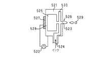
さらに例えば、ステメ型(2室型)のプリントヘッドは、図24に示すように、例えば平板型の電歪振動子527と、当該電歪振動子527と接着されていわゆるバイモルフ素子を形成する振動板528と、当該バイモルフ素子を備えたノズルユニット521と、インクが充填されると共に上記バイモルフ素子の駆動によって当該充填されたインクに圧力がかけられる圧力室525と、インクを供給するためのインク供給口524と、上記圧力室525に繋がると共に上記インク供給口524からのインクが通るインク供給路530と、上記インク供給路530に充填されているインクをインク液滴529として吐出するためのノズル523及びオリフィス部526と、上記バイモルフ素子に印加する電圧を発生する電圧発生器522とを有してなり、上記電圧発生器522からの電圧を上記バイモルフ素子に印加することで生ずる圧力室525内の圧力が上記インク供給路530に伝達され、この圧力によって、インク液滴529を吐出させるようにする。
【0010】
また、上記オンデマンド型インクジェットプリンタのプリントヘッドにおいて、インク液滴を吐出するための方式の一つである上記発熱素子を使用する方式では、当該発熱素子によるインク溶液の気化現象を利用して、インク液滴を吐出する。
【0011】
この発熱素子を用いたプリントヘッドは、図25に示すように、ノズルユニット531に設けられたノズル533内に、発熱素子537を設け、この発熱素子537に電力を加え、その発生熱エネルギでノズル533内のインクを瞬時に気化させ、この気化により発生する泡の圧力で生ずるインクの体積変化により、オリフィス部536からインク液滴539を吐出させるものである。
【0012】
すなわち、当該発熱素子を用いたプリントヘッドでのインク液滴の吐出動作を順番に説明すると、先ず、図25のAに示すように、発熱素子537に電力を加えると、当該発熱素子537に接するインクが加熱沸騰して小さな泡が複数発生する。この複数の小さな泡は図25のBに示すように一つの大きな泡540に纏まり、当該泡540の急激な圧力によって当該ノズル533内のインクがオリフィス部536から押し出される。次に、上記発熱素子537への電力がカットされると、図25のCに示すように、上記泡540は急激に縮まり、上記ノズル533内の圧力も急激に減少する。これにより、上記オリフィス部536から押し出されたインクは、ノズル533内のインクと切り離され、図25のDに示すように、インク液滴539として吐出されることになる。
【0013】
また、上述したようなオンデマンド型インクジェットプリンタにおいて、中間調を再現するためには、ピエゾ素子等の電歪振動子又は発熱素子に与える電圧やパルス幅を変化させて吐出するインク液滴の大きさを制御し、記録紙上に形成される印画ドットの径を可変とすることで諧調を表現するものや、印画ドット径は変化させずに1画素を例えば4×4のドットよりなるマトリクスで構成し、このマトリクス単位でいわゆるディザ法を用いて諧調表現を行うもの等がある。
【0014】
【発明が解決しようとする課題】
ところで、上述したような従来のオンデマンド型インクジェットプリンタは、プリントヘッドのノズルユニット内に複数のノズルを配するいわゆるマルチノズル構成をとっていることが多い。
【0015】
このようにマルチノズル構成をとると、個々のノズルの製造上のバラツキによって、設計上得られるはずの解像度よりも実質的な解像度が低下し、また印画階調レベルも不正確となり均一な品質の印画ができないことがある。さらに、個々のノズルの使用中の経時変化によっても、上記同様の問題が発生してくる。
【0016】
このようなことから、個々のノズルの製造上のバラツキを少なくするため、及び経時変化によるバラツキをも少なくするために、個々のノズルの構造や形状等に高い精度が要求され、このためプリントヘッド製造時のコストが高くなっている。さらに、経時変化による影響を少なくするため等の理由から、個々のノズルの構造にも制約があり、また、使用するインクの特性も厳密に管理しなければならず高コスト化が避けられなかった。
【0017】
そこで、本発明はこのような実情に鑑みてなされたものであり、例えばマルチノズルのプリントヘッドを安価に製造でき、また実質解像度を上げ、かつ印画階調レベルも正確にできて均一な品質の印画を可能とし、さらに経時変化に対しても対応できるプリンタ装置を提供することを目的とする。
【0018】
【課題を解決するための手段】
本発明のプリンタ装置は、記録媒体上に形成されるインクドット径を変化させて中間調の印画を行うプリンタ装置において、インクが導入される複数の圧力室と、複数の圧力室と各々連通する複数のノズルと、複数のノズルにそれぞれ対応して設けられ、印画信号に応じて複数の各圧力室内のインクを加圧する複数の加圧手段と、複数の加圧手段の各々に対応する印画信号を補正する補正手段とを有し、補正手段は、少なくとも予め設定された補正データを記憶する記憶手段と新たに補正値を入力するインターフェイスとを有し、記憶手段から読み出した補正データをインターフェイスから入力された補正値で補正し、この補正後の補正データで印画信号を補正することで、上述の課題を解決する。
【0019】
また、本発明のプリンタ装置は、定量媒体と吐出媒体との混合濃度を変化させて中間調の印画を行うプリンタ装置において、吐出媒体が導入される複数の第1の圧力室と、定量媒体が導入される複数の第2の圧力室と、第1の圧力室に各々連通する複数の第1のノズルと、第2の圧力室に各々連通すると共に複数の第1のノズルの各々と対応して近接配置される複数の第2のノズルと、複数の第1のノズルにそれぞれ対応して設けられ、印画信号に応じて複数の第1の各圧力室内の吐出媒体を加圧する複数の第1の加圧手段と、複数の第2のノズルにそれぞれ対応して設けられ、印画信号に応じて複数の第2の各圧力室内の定量媒体を加圧する複数の第2の加圧手段と、複数の第1又は第2の少なくとも何れか一方の加圧手段の各々に対応する印画信号を補正する補正手段とを有し、補正手段は、少なくとも予め設定された補正データを記憶する記憶手段と新たに補正値を入力するインターフェイスとを有し、記憶手段から読み出した補正データをインターフェイスから入力された補正値で補正し、この補正後の補正データで印画信号を補正することで上述した課題を解決する。
【0020】
すなわち、本発明のプリンタ装置によれば、ノズル及び加圧手段の製造時のバラツキ及び経時変化によるバラツキに対応して、印画信号を補正している。
【0021】
【発明の実施の形態】
以下、本発明の好ましい実施の形態について図面を参照にしながら説明する。
【0022】
先ず、本発明のプリンタ装置の第1の構成例について説明する。
【0023】
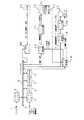
当該第1の構成例のプリンタ装置は、図1に示すように、電歪(誘電体に電場をかけたときに、変形,歪を生ずる現象)を起こす電歪振動子を使用したインクジェットプリントヘッド(以下、プリントヘッドと呼ぶ)16を有し、例えばいわゆるインクドット径変調方法を使用して所望の中間調プリントを得るようにし、後述するようにプリントヘッド16の個々のノズルの製造時及び経時変化によるのバラツキを補正するためのシェーディング補正を、プリントヘッド16を制御するアナログ処理部で実行するようにしたものである。
【0024】
なお、上記インクドット径変調方法は、プリントヘッドの電歪振動子に印加する電圧レベルを印画すべき画像のデータに対応して変化させ、当該印加電圧レベルの変化に対応して電歪振動子を変位させ、ノズルから吐出するインク液滴の体積を当該電歪振動子の変位に対応して変化させることによって、所望の中間調プリントを得るようにする方法である。
【0025】
ここで、第1の構成例のプリンタ装置は、上記吐出するインク液滴の体積を定量する上記インクドット径変調方法を使用するプリントヘッド16の一具体例として、例えば図2の原理図にて示すような、いわゆる振動子平板型のものを採用している。
【0026】
すなわち、この図2の原理に示すプリントヘッドは、印加電圧に応じて図中矢印SD方向に変位する圧電セラミックにより構成される平板型の電歪振動子117と、当該平板型電歪振動子117と接着される振動板118と、これら電歪振動子117及び振動板118を備えたノズルユニット111と、当該ノズルユニット111の内部からなるインク室115と、当該インク室115に充填されるインクが供給されるインク供給口114と、上記インクをインク液滴119として吐出するためのノズル113及びオリフィス部116と、上記電歪振動子117に印加する電圧を発生する電圧発生器112とを有してなり、印画すべき画像のデータに応じた電圧を上記電圧発生器112から発生して上記電歪振動子117に印加することにより生ずるインク室115内の体積変化によって、インク液滴119を吐出させるようにするものである。
【0027】
ここで、本構成例におけるプリントヘッド16は、上記図2の原理図に示すような構成を多色のマルチノズルを有するものに適用している。すなわちこのマルチノズル構成のプリントヘッド16は、図3に示すように、例えばm個のノズルに対応してm個の電歪振動子1271〜127mが設けられ、これらm個の電歪振動子1271〜127mにそれぞれ電圧が印加されることで、m個のオリフィス部1261〜126mからインク液滴129が吐出されるようになっている。なお、上記電歪振動子の材質としては、チタン酸ジルコン酸鉛(PbTiO3・PbZrO3)や、チタン酸バリウム(BaTiO3)からなる圧電セラミック、水晶、ロッシェル塩等がある。
【0028】
ところで、上述したようなマルチノズル構成のプリントヘッドにおいては、前述したように、個々のノズルの製造上のバラツキによって、設計上得られるはずの解像度よりも実質的な解像度が低下し、また印画階調レベルも不正確となり均一な品質の印画ができなことがある。さらに、個々のノズルの使用中の経時変化によっても、上記同様の問題が発生してくる。
【0029】
このため、本構成例においては、上記個々のノズルの製造上のバラツキを原因とする印画濃度ムラを少なくするために、製造時に前もって個々のノズルの特性を測定し、その計測値を電歪振動子に印加する電圧レベルに反映させることで、個々のノズルのバラツキを補正する(シェーディング補正を行う)ようにしている。
【0030】
すなわち、図1に示す本発明のプリンタ装置では、上記プリントヘッド製造時に、当該プリントヘッド16の個々のノズルについて、電歪振動子に印加する印加電圧レベルと記録紙上に形成されたドットサイズ及びドット内の濃度分布及びドット形状との関係を、当該プリントヘッド16の吐出特性として標準的なテスト装置(設計値を設定可能な装置)にて求め、当該求めた吐出特性を数値化した計測値そのもの、或いは当該計測値から求めたデータをシェーディング補正用データとして生成する。このプリントヘッド製造時のシェーディング補正用データは、当該プリントヘッドに付加されるメモリ手段(例えばP−ROM,EP−ROM,EE−PROM,フラッシュメモリ,ディップスイッチ,ジャンパスイッチ等)に保存する。なお、図1の例では、上記メモリ手段として、EE−PROM10を用いている。また、当該EE−PROM10は、プリントヘッドを備えたカートリッジに物理的及び電気的に接続されている場合のみならず、EE−PROM基板として単体で存在し、使用者が当該プリントヘッドをプリンタ本体に接続するときに、当該単体で存在するEE−PROM基板をプリンタ本体内に接続するようにしてもよい。或いは、上記計測値をプリントヘッドの販売時に添付し、このプリントヘッドを購入した使用者が、当該プリントヘッドの使用時に上記添付された計測値を入力するようなことも可能である。
【0031】
さらに、本構成例においては、上述したプリントヘッドの使用時の経時変化を原因とする印画濃度ムラを減少させるために、一旦個々のノズルを駆動することで、それぞれの吐出特性を測定し、その計測値を電歪振動子に印加する電圧レベルに反映させることで、個々のノズルのシェーディング補正を行うことをも可能となされている。
【0032】
すなわち、本発明の第1の構成例において、当該プリンタ装置の使用者は、実際に希望する画像をプリント出力する前に(或いは定期的に)、シェーディング補正用印画サンプルをプリント出力し、その出力された結果を観察することで、プリントヘッド内の各ノズルのうち、吐出状態が変化してしまったノズルを特定し、その結果を基にして上記EE−PROM10内に格納されているシェーディング補正用データを最適な値に変更して用いるようにする。具体的には、例えば、使用者が上記シェーディング補正用印画サンプルを観察して求めた補正値を、当該使用者がマンマシンインターフェイス部2を介して入力し、EE−PROMインターフェイス部11において、上記EE−PROM10から読み出された前記シェーディング補正用データを当該入力された補正値にて変更する。或いは、個々のノズルを駆動するときに、上記シェーディング補正用データを変更するための補正値を自動的に計測し、当該計測した補正値から求めたシェーディング補正用データを、上記メモリ手段(例えばEE−PROM,フラッシュメモリ,S−RAM,D−RAM等)に保存するようなことも可能である。上記補正値の自動的な計測は、例えば、LED(発光ダイオード)やレーザ発振器と、フォトトランジスタやフォトダイオード等との組み合わせにより、飛んでいるインク液滴の体積を計測したり、記録紙上に付着したインクドットの大きさ或いは濃度を同様に計測し、この計測結果に基づいて生成するようなことが可能である。
【0033】
なお、各ノズルの特性のバラツキを取り除くためにプリントする上記シェーディング補正用印画サンプル出力時において、その校正用の基準となるノズルという絶対的なものはないので、ヘッド出荷時におけるEE−PROMへのデータ書き込み時には、設計において想定した吐出特性を持つノズルが校正用のノズルを持つヘッドとなり、これを基にしてそれぞれのヘッドの個々のノズルの吐出特性値を決める。また、使用者がマンマシンインターフェイス部を介して補正を行うときには、校正用のノズルを持ったヘッドがないことが想定される。そのときは、シェーディング補正すべきヘッドによってシェーディング補正用印画サンプルを出力し、そのヘッドの過半数を占めることになる平均的で標準な略々均一の吐出特性を持つ当該過半数のノズルを校正用のノズルと見なすことができる。その標準的なノズルから離れた吐出特性を持つノズルに対して、標準的な吐出特性に近づくようなシェーディング補正を行うことによって、ノズル間のバラツキを減少させ、均一なプリントが可能となる。
【0034】
上記製造時に求めたシェーディング補正用データ、及び経時変化に対応したシェーディング補正用データを用いたシェーディング補正は、図3に示したような多色でそれぞれがマルチノズルを有するプリントヘッドのみならず、単色単一ノズルを持つインクジェットプリントヘッド、多色でそれぞれ単一ノズルを持つインクジェットプリントヘッド、単色マルチノズルを持つインクジェットプリントヘッド等の何れにも適用することができる。
【0035】
上述したようなプリントヘッドを有する図1の構成例のプリンタ装置の構成及び動作について、図4に示す各部のタイミングチャートを参照しながら、順に説明する。
【0036】
先ず、当該プリンタ装置の使用者が、希望する画像のプリントを開始する場合には、マンマシンインターフェイス部2或いはデータ入力インターフェイス部4を経由して、プリント開始要求を意味する命令を入力し、このプリント開始要求命令信号がCPUシステムバス8を介してCPU5(或いはDSP)に送られる。このCPU5は、ROM6に格納されたプログラムデータに基づいて各種信号処理及び各部の制御を行うものである。ここで、上記マンマシンインターフェイス部2には、端子1を介して、使用者の例えばキー操作によるキー入力が上記プリント開始要求命令信号として入力される。一方、上記データ入力インターフェイス部4には、端子3を介して、例えばホストコンピュータからの印画すべき画像データが入力データとして入力されるようになされており、また、ホストコンピュータとの間で双方向に通信がなされる入力データ制御信号の一つとして、当該ホストコンピュータからの上記プリント開始要求命令信号が入力される。
【0037】
上記プリント開始要求命令が供給されてプリント処理状態になると、当該プリンタ装置は、データ入力インターフェイス部4を通じて、印画すべき画像データを受け入れ可能である旨を示す制御信号をホストコンピュータに返す。ホストコンピュータは、当該制御信号を受け取ると上記印画すべき画像データを当該プリンタ装置に供給する。プリンタ装置では、端子3及びデータ入力インターフェイス部4を介して受け取った上記画像データを、CPUシステムバス8を介してRAM7に送り格納する。このとき、データ入力インターフェイス部4は、RAM7上がオーバーフローしないように上記画像データの入力を制御する。すなわち、データ入力インターフェイス部4は、RAM7内の上記画像データを格納可能な全記憶領域に画像データが格納された時点で、上記ホストコンピュータに対して画像データの入力を止める旨を要求する制御信号を出力する。
【0038】
上記RAM7上に格納された印画すべき画像データが数ライン分に達すると、CPU5は当該画像データを印画するために必要な処理を開始し、当該画像データを印画するための印画データに置換する。なお、RAM7の記憶容量が印画する画像全体に対応する容量を有している場合には、全部の画像データを格納し終わってから、上記印画するために必要な処理を行うようにしてもよい。また、RAM7の記憶容量が印画する画像全体に対応する容量を有していない場合には、上述のように必要なライン数分の画像データのみを格納し、データ入力インターフェイス部4において入力データ制御信号(上記ホストコンピュータに対して画像データの入力を止める旨を要求する制御信号)による制御を行う。上記画像データが置換された印画データは、同一のRAM7上の上記印画データの基になった画像データが格納されている場所とは異なる他の場所に格納する。或いは、上記画像データが置換された印画データは、同一のRAM7上の上記印画データの元になった画像データが格納されていた場所に重ね書きして格納することも可能である。
【0039】
上記画像データを置換した印画データが、プリントヘッドを駆動する数だけ上記RAM7上に格納されたならば、CPU5は、当該RAM7に格納された印画データを読み出して図4に示すような印画データ信号としてD/A変換部13に送る。なお、上記RAM7上に印画データを格納する際の上記プリントヘッドを駆動する数とは、例えばノズル数が数10個程度設けられたプリントヘッドを駆動してプリントを行ういわゆるヘッド駆動型プリンタ(例えばシリアル型プリンタ)の場合には、当該プリントヘッドの1スキャン分に対応する数であり、また、ノズル数が記録画サイズ分だけ設けられたプリントヘッドを有するラインヘッド型プリンタの場合には、1ライン分に対応する数である。上記ヘッド駆動型プリンタ及びラインヘッド型プリンタの詳細な説明については後述する。
【0040】
上記CPU5は、上記RAM7に格納された印画データをD/A変換部13に送ると、それと同時に、モータ制御部19へモータ駆動制御信号を送る。当該モータ制御部19は、上記モータ駆動制御信号に基づいてモータ駆動信号を生成し、このモータ駆動信号がモータドライブ部20に送られる。このモータドライブ部20は、上記モータ駆動信号を、紙送りモータ及びヘッド送りモータからなるモータ部21を駆動できる電圧及び電流値となるモータパルスに変換し、当該モータパルスをモータ部21に送る。このとき、上記ヘッド駆動型プリンタである場合には、ヘッド送りモータを動作させることになる。
【0041】
上記ヘッド送りモータが起動し、プリントヘッドのノズルが記録紙上の印画すべき位置に達したことをヘッド位置検出センサ17が検出したとき、タイミング制御部18は、上記ヘッド位置検出センサ17からの当該検出信号に基づいて、図4に示すように上記D/A変換部13に対してD/A変換トリガ信号を出力する。また、当該タイミング制御部18は、図4に示すように、同時にモータ制御部19に対してもモータ駆動トリガ信号を出力すると共に、補正データD/A変換部12に対して補正データD/A変換トリガ信号を出力する。
【0042】
ここで、上記補正データD/A変換部12は、前述したようなシェーディング補正用データの信号が供給されるようになされている。すなわち、図4に示すように、EE−PROM10に格納されている前記プリントヘッドの製造時に求められたシェーディング補正用データ(以下、EE−PROM補正データ信号と呼ぶ)と、前記マンマシンインターフェイス部2を介して使用者が入力するプリントヘッドの経時変化に対応するためのシェーディング補正用データ(EE−PROM補正データを最終的な値に変更するための補正値、以下、マンマシンインターフェイス入力補正データ信号と呼ぶ)とが、EE−PROMインターフェイス部11に供給されるようになされており、当該EE−PROMインターフェイス部11にて上記EE−PROM補正データ信号を上記マンマシンインターフェイス入力補正データ信号にて補正して得た信号が、シェーディング補正用データ信号として、上記補正データD/A変換部12に供給されるようになっている。したがって、この補正データD/A変換部12では、上記タイミング制御部18からの補正データD/A変換トリガ信号に応じて、上記シェーディング補正用データ信号を当該信号が示す値に対応した電圧レベルに変換する。この補正データD/A変換部12からの電圧レベルの信号は、図4に示すような補正信号としてシェーディング補正部14に送られる。なお、上記EE−PROM10に保存されるシェーディング補正用データや、マンマシンインターフェイス部2から入力されるシェーディング補正用データの具体例については後述する。
【0043】
また、CPU5はタイミング制御部18の状態をみており、図4に示すように、上記タイミング制御部18からのD/A変換トリガ信号が上記D/A変換部13に供給されたときに、上記RAM7に格納されていた印画データ信号を上記D/A変換部13に送るようにしている。D/A変換部13では、上記D/A変換トリガ信号に応じて、上記RAM7からの印画データ信号を当該信号が示す値に対応した電圧レベルに変換する。このD/A変換部13からの電圧レベルの信号は印画信号としてシェーディング補正部14に送られる。
【0044】
当該シェーディング補正部14では、上記D/A変換トリガ信号に応じて上記D/A変換部13から供給された上記電圧レベルの印画信号と、上記D/A変換トリガ信号に同期する上記補正データD/A変換トリガ信号に応じて上記補正データD/A変換部12から供給された上記電圧レベルの補正信号とから、図4に示すような実際の印画のために使用する電圧レベルのヘッド駆動信号を生成し、このヘッド駆動信号をヘッドドライブ部15に送る。すなわち、当該シェーディング補正部14からは、EE−PROM10内に保存されているプリントヘッド製造時に求められたシェーディング補正用データと、使用者がマン−マシンインターフェイス部から入力した経時変化に対応するためのシェーディング補正用データとから求められた、実際に使用されるプリントヘッドの個々のノズルの吐出特性を補正することができるヘッド駆動信号が出力される。なお、このシェーディング補正部14では、例えば上記印画信号と補正信号とを加算することでヘッド駆動信号を生成する。
【0045】
上記ヘッド駆動信号は、ヘッドドライブ部15に送られ、ここでプリントヘッド16の電歪振動子を変位させるのに必要な電力にまで増幅され、これが当該プリントヘッド16の電歪振動子へ図4に示すような印加信号として送られる。
【0046】
当該プリントヘッド16では、上記印加信号の電圧レベルにしたがい、前記図2に示した電歪振動子117が図2中の矢印SDに示す方向に変位し、振動板118を押し曲げる。これにより、インク室115内の体積が減少し、このインク室115内に充満しているインクがパスカルの原理で押しつけられる。インク室115内のインクは、ノズル113を介してオリフィス部116から吐出し、インク液滴119として記録紙上にまで飛翔する。インク液滴119は、記録紙上で、あるドットサイズを持ったインクドットを形成する。このインクドットは、電歪振動子117に印加した電圧レベルに対応したサイズになる。
【0047】
また、モータ制御部19は、CPU5からのモータ駆動制御信号に基づいて、プリントヘッド16の駆動に同期して必要に応じて記録紙を送るためのモータ駆動信号を生成し、このモータ駆動信号がモータドライブ部20を介してモータ部21の紙送りモータに供給され、これにより記録紙が送られる。
【0048】
以上の動作を繰り返すことで、紙送り、ヘッド送り、ヘッドへの電圧の印加が行われる。
【0049】
なお、上記プリンタヘッド16が複数のヘッドからなるマルチヘッドとなっており、ノズル数が非常に多いような場合には、ヘッド自体にIC(集積回路)を搭載してヘッドに接続する配線数を減らすようにすることも可能である。また、画像データの信号処理を行うCPU5では、γ補正やカラーの場合の色補正等も行う。
【0050】
上述した図1のプリンタ装置におけるプリント動作の処理の流れは、図5のフローチャートのようになる。
【0051】
すなわちこの図5において、プリンタ装置の電源がONされると、ステップS1ではプリンタ装置の初期化が行われる。次のステップS2では、プリント開始要求命令信号が供給されたか否かの判断が行われる。このステップS2において、プリント開始要求命令信号が供給されていないときには、ステップS3に進む。
【0052】
このステップS3では、前記経時変化によるノズルの吐出特性の変化に対応するための前記シェーディング補正用印画サンプルをプリントするか否かの判断を行う。このステップS3においてプリントする場合にはステップS4にて当該補正用印画サンプルをプリントした後、ステップS2に戻る。また、当該ステップS3において、補正用印画サンプルのプリントを行わないときには、ステップS5にてマンマシンインターフェイス部2から補正データ信号の入力が有るか否かの判断を行う。このステップS5にて入力がないと判断したときにはステップS2に戻り、有ると判断したときにはステップS6に進む。このステップS6では各ノズルの吐出特性値を、マンマシンインターフェイス部2からのシェーディング補正用データ信号として入力する。
【0053】
一方、ステップS2にて、プリント開始要求命令信号が入力されたと判断したときには、ステップS7以降の処理に進む。ステップS7では記録紙を所定のプリント開始位置まで送る給紙動作が行われ、ステップS8では画像データがRAM7上に1スキャン分格納されたか否かの判断を行う。このステップS8で未だ格納されていないと判断したときには、当該ステップS8の処理を繰り返し、格納されたと判断したときにはステップS9に進む。ステップS9では、上記1スキャン分の画像データから印画データを生成し、この印画データを用いた1スキャン分のプリント処理を行い、次のステップS10に進む。ステップS10ではプリントが終了したか否かの判断を行い、終了していないときにはステップS8に戻り、終了したときにはステップS11に進む。このステップS11では記録紙が排出され、次のステップS12では次ページのプリントを行うか否かの判断をする。このステップS12にて次ページのプリントを行うときにはステップS7に戻り、次ページのプリントを行わないと判断したときには、ステップS2に戻る。
【0054】
次に、上記EE−PROM10に保存されるシェーディング補正用データと、マンマシンインターフェイス部2から入力されるシェーディング補正用データの具体例について説明する。
【0055】
先ず、EE−PROM10に保存するシェーディング補正用データ(EE−PROM補正データ)の具体例について述べる。
【0056】
当該EE−PROM10には、例えば、ヘッド種別とヘッド番号とノズル番号と各ノズルの特性値とからなるデータを保存する。マルチノズルのプリントヘッドの場合、同一のヘッド種別とヘッド番号に対して、複数のノズル番号とその特性値が対応付けられることになる。すなわち、上記ヘッド種別としては例えばシアン,マゼンダ,イエロー等の色に対応するヘッドの種類を示すデータが、上記ヘッド番号としてはロット番号を示すデータが、上記ノズル番号としては各ヘッド中の複数のノズルのうちの何番目かを示すノズルの番号のデータが、上記特性値としては各ノズル番号に対応する各ノズルのそれぞれの補正用吐出特性値のデータ(すなわちシェーディング補正用データ)が保存される。
【0057】
なお、上記補正用吐出特性値の一例として、印加電圧とインクドット直径との関係が設計値と同じであるノズル(すなわち補正の必要がないノズル)に対しては例えば「±0」の値が、また、最大入力値のときにインクドット直径が設計値よりも10%大きくなるような電圧を印加しなければならないノズルに対しては例えば「+10」の値が、最大入力値のときにインクドット直径が設計値よりも10%小さくなるような電圧を印加しなければならないノズルに対しては例えば「−10」の値が、最大入力値のときにインクドット直径が設計値よりも50%大きくなるような電圧を印加しなければならないノズルに対しては例えば「+50」の値が設定される。すなわち、マルチノズルのプリントヘッドのうちのあるノズルからインク液滴を吐出する場合において、EE−PROM10内の当該ノズルに対応する上記補正用吐出特性値が、例えば上記最大入力値のとき、設計値より10%大きなインクドット直径になるような電圧を加える上記「+10」の値を持っているとすると、当該ノズルは設計値よりも吐出特性が悪く、吐出インク液滴体積が少なくなることを意味している。このため、当該ノズルからの実際のインク吐出時においては、印加電圧を上記補正用吐出特性値に合うように上げてインク液滴の体積を増加させ、設計時に予定したインクドット径になるようにする。
【0058】
次に、マンマシンインターフェイス部2から入力されるシェーディング補正用データ(マンマシンインターフェイス入力補正データ信号)の具体例について説明する。
【0059】
このマンマシンインターフェイス部2から入力されるシェーディング補正用データを決定するには、先ず、図6に示すようなシェーディング補正用印画サンプルをテストプリントする。すなわち、この図6に示すように、例えばm個のノズルを有するプリントヘッドの場合には、当該m個の個々のノズルに対応して図中L1〜Lmで示すような線を記録紙上にプリントする。使用者は、当該記録紙にプリントされた個々のノズルに対応する線L1〜Lmを観察(例えば大部分の標準的なノズルから吐出印画した各線に比べて、あるノズルから吐出印画した線の濃度がどの位高いか或いはどの位低いかを観察)することにより、それぞれのノズルの吐出特性を目視にて判定し、マンマシンインターフェイス部2を通したキー入力により、当該ノズルから吐出するインク液滴の体積を増加/減少させる指示を行う。
【0060】
例えば、当該プリンタ装置に例えば液晶表示手段が設けられている場合には、当該液晶表示手段に例えば図7に示すようなヘッド種別及びヘッド番号を示す表示(<ヘッド>)とノズル番号を示す表示(<ノズル>)と特性値を示す表示(<トクセイ>)がなされているときに、プリンタ装置に備えられているキーK−,K+を操作することにより、個々のノズルの特性値を変更する指示を行う。ここで、キーK−を1回押すと特性値が−1となり、キーK+を1回押すと特性値が+1となされる。図7の例では、ヘッド種別及びヘッド番号がシアンのヘッド(表示は<ヘッド>シアン)でノズル番号がNo.5(表示は<ノズル>No.5)のときの当該No.5のノズルの特性値を+5にした例を示している。すなわち、前述した補正用吐出特性値の例に対応させて説明すると、当該No.5のノズルに対しては、最大入力値のときにインクドット直径が設計値よりも5%大きくなるような電圧が印加されることになる。
【0061】
マンマシンインターフェイス部2から入力されるシェーディング補正用データを決定する際には、上述のような操作を、それぞれ補正が必要な各ノズルに対して行う。その後、当該補正の効果を確かめるたいと使用者が考える場合には、再度シェーディング補正用印画サンプルのテストプリントを行うようにする。
【0062】
なお、上述したようにして設定した上記EE−PROM10に保存されるシェーディング補正用データとマンマシンインターフェイス部2から入力されるシェーディング補正用データとの取り扱い方については、以下のようにすることができる。すなわち、マンマシンインターフェイス部2から入力したシェーディング補正用データ(各ノズルの新しい特性値)は、当該データを入力した時点で、前述したように、すぐにEE−PROM10に保存するようにしてもよい。或いは、すぐにEE−PROM10には保存せずに、元々EE−PROM10内に保存されていた補正用データと、マンマシンインターフェイス部2から入力した新しい補正データの両方から、プリントするときに必要な補正データを求めてから、プリントアウトするようにしてもよく、このときは、使用者が新しくマンマシンインターフェイス部2から入力した補正データを保存する操作を行ったときに、EE−PROM10に保存するようにしてもよい。なお、上記プリントに必要な補正データは、(EE−PROM補正データの値)+(キーK+の押された回数)−(キーK−の押された回数)の計算式により求められる。
【0063】
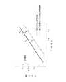
ここで、上記EE−PROM10からのシェーディング補正用データの値及び、マンマシンインターフェイス部2を介して供給されるシェーディング補正用データの値から最終的に得られたシェーディング補正用データの値と、プリントヘッド16の設計上の吐出特性値との関係を、図8を用いて説明する。なお、この図8の図中実線は、設計上の吐出特性曲線を示し、図中破線は、吐出特性が悪くて補正が必要なノズルの吐出特性曲線、例えば補正用吐出特性値として前記+10の値が最適となるノズルの吐出特性曲線を示している。ここで、補正用吐出特性値が+10となっているということは、そのノズルが、前述したように最大入力時(入力レベルが0〜255のレベルで示されるときには255)に、インクドットの直径が設計値よりも10%大きくなるような印加電圧を加えれば適正な吐出が得られるノズルであることを意味している。
【0064】
すなわち、この図8において、図中実線で示す上記設計上の吐出特性曲線上の例えば点PAは、最大入力レベル(255)のときに設計上のドット径dAが得られる印加電圧がVAであることを示している。また、この図8において、図中破線で示す吐出特性曲線上の例えば点PCは、最大入力レベル(255)のときに上記設計上の吐出特性曲線上の点PAの場合と同様に印加電圧をVAとすると、当該ノズル(補正用吐出特性値が+10で最適となるシェーディング補正が必要なノズル)から吐出されて記録紙上に形成されるドット径がdCとなることを示している。したがって、当該シェーディング補正が必要なノズルにおいて、上記設計上の吐出特性曲線上の点PAの場合と同じドット径dAを得るためには、当該設計上の吐出特性曲線上の点PAでのドット径dAの10%増しのドット径dD、つまり設計上の吐出特性曲線上では点PDとなるような電圧VB(図中破線で示す吐出特性曲線上では点PBに対応する)を印加すれば、上記ドット径dAと等しいドット径dBが得られることになる。
【0065】
最大入力レベル以下(<255)の場合も同様であり、前もって実験によって決定したシェーディング補正が必要なノズルの吐出特性曲線(図8の例では図中破線で示す曲線)と設計上の吐出特性曲線とを用い、最初に入力レベル(0〜255)から設計上の印加電圧を求め、その後それぞれのノズルの実際の吐出特性曲線と設計上の吐出特性曲線との差より、上記設計上の印加電圧を補正し、実際に各ノズルに対応する電歪振動子へ印加する電圧を決める。
【0066】
また、インクドット径と印画濃度との関係は、前もって実験によって、設計上の吐出特性を持つノズルによって印画されたプリントサンプルの光学濃度(Optical Density:O.D)を測定して求め、これによりその曲線にのった理想的ノズルにおける入力レベル(0〜255)と印画濃度との関係を求める。
【0067】
なお、図9には、各入力レベルと光学濃度D,インクの面積率A,ドット直径r(ただしr=(A/π)1/2),300dpi(ドット間隔は80μm)での実際のドット直径の関係を表にして示している。RBがインクの反射率を、RWが紙の反射率を示すとき、上記光学濃度Dは、次の式(1)のようにして求められる。
【0068】
D=−log(RBA+RW(1−A)) (1)
また、インクの光学濃度ODB=2.0とするにはインクの反射率RB=0.01でなければならず、同じくODB=1.5とするにはインクの反射率RB=0.0316でなければならず、さらに紙の光学濃度ODW=0.1とするには紙の反射率RW=0.794でなければならないと仮定すると、上記式(1)からインクの面積率Aは式(2)のようにして求められる。
【0069】
A=(1/0.7624)(−10−D+0.794) (2)
この図9に示す表から、例えば300dpiのプリント時に、最小ドット直径に比べて最大のドット径はその1.3〜1.6倍の直径になればよいことがわかる。なお、最小ドット径が例えば60μmのときは、最大ドット径は78μm〜96μmとなる。
【0070】
次に、図10には、本発明の第2の構成例のプリンタ装置として、例えば吐出するインク液滴の濃度を定量するいわゆる多濃度インク混合型インクドット濃度変調方法(インクドット内濃度変調方法)を使用して所望の中間調プリントを得るプリントヘッドを有し、当該プリントヘッドの個々のノズルの製造時及び経時変化によるのバラツキを補正するためのシェーディング補正を、このプリントヘッドを制御するアナログ処理部で実行するようにしたものを示す。なお、この図10において、前述した図1と同じ構成要素には同一の指示符号を付し、これらの説明については省略する。
【0071】
ここで、上記多濃度インク混合型インクドット濃度変調方法は、プリントヘッドの電歪振動子に印加する電圧レベルを印画すべき画像のデータに対応して変化させ、当該印加電圧レベルの変化に対応して電歪振動子を変位させ、混合するインク液の体積を当該電歪振動子の変位に対応して変化させることによって、所望の中間調のプリントを得るようにする方法である。なお、この多濃度インク混合型インクドット濃度変調方法における上記インク液の混合の方法としては、インク液滴をノズルから吐出する前にインクヘッド内にて濃度の高いインクと濃度の低いインク(又は透明溶媒)とを上記電歪振動子の変位に応じて定量混合させた後、インクヘッドから吐出させる方法か、或いは、インク液滴吐出時に、濃度の高いインクと濃度の低いインク(又は透明溶媒)とをそれぞれ単独で上記電歪振動子の変位に応じて定量しながら吐出させ、それらが飛行中或いは記録紙上に着いた後に混合されて、一つのインクドットを形成する方法が用いられる。なお、上記電歪振動子の材質としては、第1の構成例同様にチタン酸ジルコン酸鉛(PbTiO3・PbZrO3)や、チタン酸バリウム(BaTiO3)からなる圧電セラミック、水晶、ロッシェル塩等が挙げられる。
【0072】
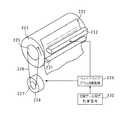
図10に示すプリンタ装置では、上記多濃度インク混合型インクドット濃度変調方法を使用するプリントヘッドの一具体例として、図11及び図12に示すような、インク溶液と希釈液(キャリア)の2液混合型のプリントヘッド(キャリアジェット型のプリントヘッド)を採用している。なお、この図11及び図12のプリントヘッドでは、電歪振動子としてピエゾ素子を用い、特にインクを定量し、希釈液(キャリア)を吐出するプリントヘッドの例を示している。また、図11には当該プリントヘッド断面図を、図12には図11のノズル近傍の拡大図を示している。
【0073】
すなわち、この図11及び図12に示すプリントヘッドは、吐出側キャビティ138及び定量側キャビティ148を形成するキャビティユニット146と、吐出側キャビティ138及び定量側キャビティ148にそれぞれ対応する吐出側ピエゾユニット133と定量側ピエゾユニット143とにより構成される。キャビティユニット146は、定量側ノズル154及び吐出側ノズル153が形成されたオリフィスプレート136と、キャビティ側壁145と、振動板135とにより構成される。吐出側ピエゾユニット133及び定量側ピエゾユニット143は、それぞれが圧電材と導電材とを交互に積層した吐出側積層ピエゾ素子134及び定量側積層ピエゾ素子144と、これら積層ピエゾ素子134及び144のそれぞれの一方の端部を固定する支持体131と141と、これら積層ピエゾ素子134及び144と支持体131と141をキャビティユニット146にそれぞれ固定する吐出側ホルダ132及び定量側ホルダ142とにより構成される。また、定量側ノズル154の開口方向は、吐出側ノズル153の開口方向に対して約45度の角度をなすように形成される。なお、当該図11及び図12のプリントヘッドにおいて、オリフィスプレート136は例えばポリサルフォン等の樹脂を射出成形により形成し、キャビティ側壁145はドライフィルムフォトレジスト等の感光性樹脂から形成され、振動板135はニッケル等の金属板により形成されている。また、ノズル153及び154は、例えばエキシマレーザにより加工する。
【0074】
上記図11及び図12に示したようなプリントヘッドを駆動する場合、吐出側積層ピエゾ素子134及び定量側積層ピエゾ素子144には、例えば図13の(A)及び(B)に示すようなタイミングで信号電圧が与えられる。なお、図13の(A)及び(B)では、それぞれ横軸を時間とし、縦軸を電圧としている。本構成例の場合、吐出周期は1msec(周波数1kHz)であり、この間に希釈液へのインクの定量混合と、インク液滴の吐出を行う。
【0075】
すなわち、図11〜図13に示すように、希釈液は、希釈液タンク(図示せず)より供給され、供給パイプから供給溝及び希釈液供給室137を通り、吐出側キャビティ138から希釈液導入孔151に導入され、さらに当該希釈液導入孔151の希釈液が吐出側ノズル153に送られて充填される。一方、インクは、インクタンク(図示せず)より供給され、供給パイプから供給溝及びインク供給室147を通り、定量側キャビティ148からインク導入孔152に導入され、さらに当該インク導入孔152のインクが定量側ノズル154に送られて充填される。そして、図13の(a)の吐出前の待機時は、予め吐出側積層ピエゾ素子134に例えば10V(ボルト)を印加しておく。
【0076】
次に、吐出時には、図13の(b)のタイミングで吐出側積層ピエゾ素子134の印加電圧を例えば0V(ボルト)にする。これにより、当該吐出側積層ピエゾ素子134は縮小し、吐出側キャビティ138の体積が増加し内圧が負圧となって、希釈液は吐出側ノズル153に引き込まれる。これと同時に又は少し遅れて、図13の(c)のタイミングで、定量側積層ピエゾ素子144に駆動電圧として例えば10V(ボルト)が与えられ、当該積層ピエゾ素子144が長手方向に伸長することで、振動板135を介して定量側キャビティ148から定量側ノズル154に内圧が加えられ、これによりインクが定量側ノズル154から定量オリフィス155を介して外部に染み出し定量が行われる。この定量オリフィス155からのインクは希釈液側の吐出オリフィス156付近まで染み出し定量が行われる。この状態で、例えば図13の(f)のタイミングで図13の(g)のように吐出側積層ピエゾ素子134に駆動信号として例えば20V(ボルト)が与えられると、振動板135を介して吐出側キャビティ138から吐出側ノズル153に内圧が加わる。この内圧によって上記希釈液が吐出オリフィス156から押し出され、先に定量されて当該吐出オリフィス156付近に染み出しているインクと、当該希釈液とが一体となって所定濃度のインク液滴として吐出される。
【0077】
この後、図13の(h)のタイミングでピエゾ素子134の電圧を例えば10V(ボルト)に下げると、当該ピエゾ素子134の縮小によりキャビティ138からノズル153の内圧は負圧となり、これにより希釈液はノズル153内に引き込まれる。また、ピエゾ素子144については、図13の(d)のタイミングで駆動電圧を例えば0V(ボルト)に下げることにより、オリフィスプレート上に残ったインクはノズル154に引き込まれる。その後、図13の(i)の期間では、キャビティ138からノズル153の内圧がやがて元に戻り、これにより希釈液は図13の(j)のように毛細管圧力によりノズル153に再充填される。
【0078】
図10に示す第2の構成例におけるプリントヘッドは、上記図11及び図12に示した構成を多色のマルチノズル構成に適用している。なお、図10の構成では、プリントヘッドがプリントヘッド変調部37とプリントヘッド吐出部36とからなり、上記プリントヘッド変調部37は前述のインクの定量を行う部分に対応し、上記プリントヘッド吐出部36は前述の希釈液の吐出を行う部分に対応している。
【0079】
ところで、この第2の構成例においても、マルチノズル構成のプリントヘッドの個々のノズル(希釈液吐出用のノズル及びインク定量用のノズル、以下これらを纏めてノズルと呼んでいる)の製造上のバラツキによって、設計上得られるはずの解像度よりも実質的な解像度が低下し、また印画階調レベルも不正確となり均一な品質の印画ができなことがある。さらに、個々のノズルの使用中の経時変化によっても、上記同様の問題が発生してくる。
【0080】
このため、当該第2の構成例においても、前記第1の構成例同様に、上記個々のノズルの製造上のバラツキを原因とする印画濃度ムラを少なくするために、製造時に前もって個々のノズルの特性を測定し、その計測値を電歪振動子に印加する電圧レベルに反映させることで、個々のノズルのバラツキを補正する(ノズルのシェーディング補正を行う)ようにしている。
【0081】
すなわち、本発明の第2の構成例のプリンタ装置では、上記プリントヘッド製造時に、当該プリントヘッドの個々のノズルについて、電歪振動子としてのピエゾ素子に印加する印加電圧レベルと記録紙上に形成されたドット内の濃度分布との関係を、当該プリントヘッドの変調特性として標準的なテスト装置(設計値を設定可能な装置)にて求め、当該求めた変調特性を数値化した計測値そのもの、或いは当該計測値から求めたデータをシェーディング補正用データとして生成する。このプリントヘッド製造時のシェーディング補正用データは、当該プリントヘッドに付加される第1の構成例同様のメモリ手段に保存する。なお、図10の例でも、上記メモリ手段として、第1の構成例同様のEE−PROM10を用いている。したがって、当該EE−PROM10は、プリントヘッドを備えたカートリッジに物理的及び電気的に接続されている場合のみならず、EE−PROM基板として単体で存在し、使用者が当該プリントヘッドをプリンタ本体に接続するときに、当該単体で存在するEE−PROM基板をプリンタ本体内に接続するようにしてもよい。或いは、上記計測値をプリントヘッドの販売時に添付し、このプリントヘッドを購入した使用者が、当該プリントヘッドの使用時に上記添付された計測値を入力するようなことも可能である。
【0082】
さらに、当該第2の構成例においても、上述したプリントヘッドの使用時の経時変化を原因とする印画濃度ムラを減少させるために、前記第1の構成例と同様に、一旦個々のノズルを駆動することで、各ノズルの変調特性を測定し、その計測値を電歪振動子に印加する電圧レベルに反映させることで、個々のノズルのシェーディング補正を行うことをも可能としている。
【0083】
すなわち、本発明の第2の構成例においては、当該プリンタ装置の使用者は、実際に希望する画像をプリント出力する前に(或いは定期的に)、シェーディング補正用印画サンプルをプリント出力し、その出力された結果を観察することで、プリントヘッド内の各ノズルのうち、変調状態が変化してしまったノズルを特定し、その結果を基にして上記EE−PROM10内に格納されているシェーディング補正用データを最適な値に変更して用いるようにする。具体的には、例えば、使用者が上記シェーディング補正用印画サンプルを観察して求めた補正値を、当該使用者がマンマシンインターフェイス部2を介して入力し、EE−PROMインターフェイス部11において、上記EE−PROM10から読み出された前記シェーディング補正用データを当該入力された補正値にて変更する。
【0084】
上述したようなプリントヘッドを有する図10に示す第2の構成例のプリンタ装置の構成及び動作について、説明する。なお、当該図10の構成例でも、シェーディング補正をプリントヘッドを制御するアナログ処理部で実行する例を挙げている。また、図10の構成において前述の図1の構成と重複する部分についての説明は省略し、異なる部分のみを説明する。
【0085】
すなわち、この図10の構成において、上記補正データD/A変換部12は、前記シェーディング補正用データの信号が供給されるようになされている。すなわち、EE−PROM10に格納されている前記プリントヘッドの製造時に求められた個々のノズルの変調特性を補正するシェーディング補正用データ(EE−PROM補正データ信号)と、前記マンマシンインターフェイス部2を介して使用者が入力するプリントヘッドの経時変化に対応するためのシェーディング補正用データ(マンマシンインターフェイス入力補正データ信号)とが、EE−PROMインターフェイス部11に供給されるようになされており、当該EE−PROMインターフェイス部11にて上記EE−PROM補正データ信号を上記マンマシンインターフェイス入力補正データ信号にて補正して得た信号が、シェーディング補正用データ信号として、前記補正データD/A変換部12に供給されるようになっている。したがって、この補正データD/A変換部12では、タイミング制御部18からの補正データD/A変換トリガ信号に応じて、上記シェーディング補正用データ信号を当該信号が示す値に対応した電圧レベルに変換する。この補正データD/A変換部12からの電圧レベルの信号は、プリントヘッドの個々のノズルの変調特性を補正する補正信号としてシェーディング補正部14に送られる。
【0086】
一方、このシェーディング補正部14には、前記RAM7からの印画データ信号を、前記D/A変換部13が前記D/A変換トリガ信号に応じて変換した電圧レベルの信号が、印画信号として供給される。
【0087】
当該シェーディング補正部14では、前記D/A変換トリガ信号に応じてD/A変換部13から供給された上記電圧レベルの印画信号と、当該D/A変換トリガ信号に同期する前記補正データD/A変換トリガ信号に応じて上記補正データD/A変換部12から供給された上記電圧レベルの補正信号とから、実際の印画のために使用する電圧レベルの変調振動子駆動信号を生成し、この変調振動子駆動信号を変調振動子ドライブ部35に送る。すなわち、当該シェーディング補正部14からは、EE−PROM10内に保存されているプリントヘッド製造時に求められたシェーディング補正用データと、使用者がマン−マシンインターフェイス部から入力した経時変化に対応するためのシェーディング補正用データとから求められた、実際に使用されるプリントヘッドの個々のノズルの変調特性を補正することができる変調振動子駆動信号が出力される。なお、このシェーディング補正部14では、例えば上記印画信号と補正信号とを加算することで上記変調振動子駆動信号を生成する。
【0088】
上記変調振動子駆動信号は、上記変調振動子ドライブ部35に送られ、ここで変調用電歪振動子すなわち前記インク定量用の積層ピエゾ素子144を変位させるのに必要な電力にまで増幅され、これがプリントヘッド変調部37へ変調振動子印加信号として送られる。当該プリントヘッド変調部37には、予め決められた一定時間だけ、上記変調振動子印加信号が加えられ、その後当該変調振動子印加信号は無効とされる。これによりプリントヘッド変調部37内でのインクの定量が行われる。
【0089】
上記インクの定量が終了すると、タイミング制御部18は、上記吐出振動子ドライブ部38に対して、前記印画データ信号に応じた吐出タイミング信号を出力する。この吐出タイミング信号は、吐出振動子ドライブ部38によって、吐出用電歪振動子すなわち前記希釈液吐出用の積層ピエゾ素子134を変位させるのに必要な電力にまで増幅され、これが吐出振動子印加信号として、プリントヘッド吐出部36に送られる。当該プリントヘッド吐出部36では、前記希釈液を上記プリントヘッド変調部37によって定量されたインクと混合一体となして、前記吐出オリフィス156から吐出させる。これにより、記録紙上には所望の濃度のインクドットが形成されることになる。
【0090】
このようにして1回目のインクドットの形成が記録紙上で行われると、次のインクドットの形成に移る。すなわち、前記RAM7上に置換された次に印画すべき印画データをD/A変換部13に送り、これ以降は、前述同様の動作を繰り返す。
【0091】
その後は、前記図1の構成と同様に、モータ制御部19は、CPU5からのモータ駆動制御信号に基づいて、プリントヘッドの駆動に同期して必要に応じて記録紙を送るためのモータ駆動信号を生成し、このモータ駆動信号がモータドライブ部20を介してモータ部21の紙送りモータに供給され、これにより記録紙が送られる。これらの動作を繰り返すことで、紙送り、ヘッド送り、ヘッドへの電圧の印加,吐出が行われる。
【0092】
上述した第2の構成例のように、多濃度インク混合型インクドット濃度変調方法を採用したプリントヘッドにおける光学濃度の印加電圧との関係は例えば図14に示すようになる。
【0093】
なお、図10の例では、インク定量用の積層ピエゾ素子144の変位量を補正するようにしているが、これと同時に吐出用の積層ピエゾ素子134の変位量をも補正するようなことも可能である。
【0094】
次に、本発明の第3の構成例のプリンタ装置を図15に示す。なお、この図15において、前述した図1と同じ構成要素には同一の指示符号を付している。
【0095】
当該第3の構成例のプリンタ装置は、前述した第1の構成例と同様に、例えばいわゆるインクドット径変調方法を使用して所望の中間調プリントを得ることができるプリントヘッド16を有するものであるが、当該プリントヘッド16の個々のノズルの製造時及び経時変化によるのバラツキの補正を、プリントヘッドを制御するディジタル処理部で実行するようにしたものである。なお、この第3の構成例のプリンタ装置は、前記プリントヘッド16の一具体例として、マルチノズル構成の前記振動子平板型のものを採用している。
【0096】
すなわち、当該第3の構成例でも、前記第1の構成例同様に、上記プリントヘッド16の製造時に、個々のノズルについて電歪振動子への印加電圧レベルと記録紙上に形成されたドットサイズ及びドット内の濃度分布及びドット形状との関係を、当該プリントヘッド16の吐出特性として標準的なテスト装置にて求め、当該求めた吐出特性を数値化した計測値そのもの、或いは当該計測値から求めたデータをシェーディング補正用データとして生成し、このプリントヘッド製造時のシェーディング補正用データを、前述同様のメモリ手段に保存するようにしている。また、前述同様に、上記計測値をプリントヘッドの販売時に添付し、このプリントヘッドを購入した使用者が、当該プリントヘッドの使用時に上記添付された計測値を入力するようなことも可能である。
【0097】
さらに、この第3の構成例でも、前述の第1の構成例同様に、プリントヘッド16の使用時の経時変化に対応するために、個々のノズルの吐出特性を測定し、その計測値に基づいて個々のノズルのシェーディング補正を行うことをも可能としている。このときの個々のノズルのシェーディング補正用データは、前述の第1の構成例同様に、シェーディング補正用印画サンプルをプリント出力に基づいて求めたり、飛んでいるインク液滴や記録紙上に付着したインクドットの大きさ或いは濃度を自動的に計測して求めることが可能である。
【0098】
さらに、当該第3の構成例におけるシェーディング補正も、第1の構成例同様に、多色でそれぞれがマルチノズルを有するプリントヘッドのみならず、単色単一ノズルを持つインクジェットプリントヘッド、多色でそれぞれ単一ノズルを持つインクジェットプリントヘッド、単色マルチノズルを持つインクジェットプリントヘッド等の何れにも適用することができる。その他、この第3の構成例では、インクを吐出するための手段として、電歪振動子の代わりに、発熱素子を使用することも可能である。この場合、当該発熱素子に印加する電力及びその波形を印画すべきデータに対応して変化させることで、その発熱量を制御すると共に、当該発熱によるインク溶液の気化によって発生する圧力変化により、吐出するインク溶液の体積を変化させることで、所望の中間調プリントを可能とする。
【0099】
ここで、当該第3の構成例においては、当該プリントヘッドの個々のノズルに対するシェーディング補正を、プリントヘッドを制御するディジタル処理部で実行するようにしているが、当該シェーディング補正用データは、簡易的には例えば以下に説明するようにして求めることができる。
【0100】
例えば、印画すべき印画データをDとし、補正された印画データをD′とし、元の印画データの最高値をDmax、Dmaxを印加手段としてのプリントヘッドに加えたときに実際に出力されるインク径をバラツキがないと仮定したときの印画データをD′maxとしたとき、上記補正された印画データD′は、式(3)のようになる。
【0101】
D′=(Dmax/D′max)×D (3)
このときの補正された印画データD′の可変範囲は、実際にプリントヘッドに加えることができる範囲にクリップする。
【0102】
また、上記印画すべき印画データDと補正された印画データD′の関係が上記DmaxとD′maxの関数にしたがう場合は、式(4)のようになる。
【0103】
D′=f(Dmax,D′max)×D (4)
上記シェーディング補正は、インク径変調方式のみで全ての中間調を表現できる場合は、当該インク径変調方式のみで印画してもよい。また、このインク径変調方式のみでは全ての中間調を表現できない場合は、当該インク径変調方式に加えて、いわゆる誤差拡散法に代表されるディザ法等を併用してもよい。
【0104】
なお、上記電歪振動子の材質としては、チタン酸ジルコン酸鉛(PbTiO3・PbZrO3)や、チタン酸バリウム(BaTiO3)からなる圧電セラミック、水晶、ロッシェル塩等がある。また、当該電歪振動子から変位を取り出す形態としては、円筒型振動子、単層振動子、積層振動子、バイモルフ振動子等がある。発熱素子の方向と、インク液滴の吐出方法により、エッジ・シューター型と、サイドシューター型がある。
【0105】
以下、第3の構成例のプリント装置の構成及び動作について、図16に示す各部のタイミングチャートを参照しながら、順に説明する。なお、図1の構成と同一の部分についての説明は省略する。
【0106】
当該第3の構成例のプリンタ装置は、前記プリント開始要求命令信号が入力されてプリント処理状態になると、当該プリンタ装置は、EE−PROM10からEE−PROMインターフェイス部40を経由して、当該EE−PROM10内に保存されていた実際のプリントで使用するシェーディング補正用データを読み出して、RAM7上に保存する。そして、データ入力インターフェイス部4を通じて印画すべき画像データを受け入れ、当該画像データをRAM7に格納する。このとき、データ入力インターフェイス部4は、RAM7上がオーバーフローしないように上記画像データの入力を制御する。
【0107】
上記RAM7上に格納された印画すべき画像データは、前述同様に数ライン分に達すると、CPU5の処理によって、前記印画するための印画データに置換されると共に、当該置換された印画データは、さらに前記RAM7上に保存された実際のプリントで使用するシェーディング補正用データを用いたシェーディング補正処理がなされる。図16に示すような上記シェーディング補正がなされた実際の印画データは、同じRAM7内の他の場所に格納される。このときのシェーディング補正用データを用いた印画データの補正処理の際には、前記式(3)の演算が行われる。
【0108】
上記シェーディング補正処理がなされた印画データが、プリントヘッドを駆動する数だけ上記RAM7上に格納されたならば、CPU5は、前記第1の構成例同様に、当該RAM7に格納された当該印画データを読み出してD/A変換部13に送ると同時に、モータ制御部19へモータ駆動制御信号を送る。当該モータ制御部19以降の動作は前述の第1の構成例と同じである。
【0109】
上記D/A変換部13は、前記タイミング制御部18から前述同様のD/A変換トリガ信号が供給されると、当該D/A変換トリガ信号に応じて、上記RAM7からの補正された印画データ信号を当該信号が示す値に対応した電圧レベル及び電流値に変換する。このD/A変換部13からの信号は、印画信号としてヘッドドライブ部15に送られる。このヘッドドライブ部15以降の動作は前述の第1の構成例と同様であり、ヘッド駆動信号とヘッド印加信号及びモータ駆動トリガ信号は、図16に示すようになる。
【0110】
以上の動作を繰り返すことで、紙送り、ヘッド送り、ヘッドへの電圧の印加が行われる。
【0111】
上述した第3の構成例のプリンタ装置におけるプリント動作の処理の流れは、図17のフローチャートのようになる。なお、この図17において、ステップS21からステップS26までは、前記図5のフローチャートのステップS1からステップS6までと同じであるためこれらの説明は省略する。
【0112】
この図17のフローチャートにおいて、ステップS22にてプリント開始要求命令信号が入力されたと判断したときには、ステップS27以降の処理に進む。ステップS27では、EE−PROM10から前記シェーディング補正用データを読み出す。次のステップS28では記録紙が供給され、さらにステップS29では画像データがRAM7上に1スキャン分格納されたか否かの判断を行う。このステップS29で未だ格納されていないと判断したときには、当該ステップS29の処理を繰り返し、格納されたと判断したときにはステップS30に進む。このステップS30では、1スキャン分の画像データを印画データに置換すると共に、上記EE−PROM10から読み出したシェーディング補正用データを用いて当該印画データにシェーディング補正用の演算処理を施す。
【0113】
次に、ステップS31では、当該印画データを用いて1スキャン分のプリント処理を行い、ステップS32に進む。このステップS32ではプリントが終了したか否かの判断を行い、終了していないときにはステップS29に戻り、終了したときにはステップS33に進む。このステップS33では記録紙が排出され、次のステップS34では次ページのプリントを行うか否かの判断をする。このステップS34にて次ページのプリントを行うときにはステップS28に戻り、次ページのプリントを行わないと判断したときには、ステップS22に戻る。
【0114】
次に、この第3の構成例における上記EE−PROM10に保存されるシェーディング補正用データと、マンマシンインターフェイス部2から入力されるシェーディング補正用データも、前述の第1の構成例同様のものであるが、当該第3の構成例ではマンマシンインターフェイス部2からの入力がある場合には、EE−PROM10内のシェーディング補正用データとマンマシンインターフェイス部2からのシェーディング補正用データの両者を用いて、RAM7に保存された前記印画データを補正する。すなわち、マンマシンインターフェイス部2から入力したシェーディング補正用データは、当該データを入力した時点で、すぐにEE−PROM10に保存する。このときの元々EE−PROM10内に保存されていた補正用データと、マンマシンインターフェイス部2から入力した新しい補正データの両方から、プリントするときに必要な補正データを求める。当該補正データを求めるためには、前述同様に、(EE−PROM内のデータの値)+(キーK+の押された回数)−(キーK−の押された回数)の計算式を用いる。
【0115】
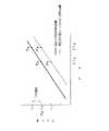
ここで、第3の構成例における上記EE−PROM10からのシェーディング補正用データの値及び、マンマシンインターフェイス部2を介して供給されるシェーディング補正用データの値から最終的に得られたシェーディング補正用データの値と、プリントヘッド16の設計上の吐出特性値との関係を、図18を用いて説明する。なお、この図18は、横軸がデータとなっていること以外は前記図8と同様に示されるものである。
【0116】
すなわち、この図18は、図中実線で示す上記設計上の吐出特性曲線上の例えば点PAは、最大入力レベル(255)のときに設計上のドット径dAが得られる印画データの値がDTAであることを示している。また、この図18において、図中破線で示す吐出特性曲線上の例えば点PCは、最大入力レベル(255)のときに上記設計上の吐出特性曲線上の点PAの場合と同様に、使用する印画データの値をDTAとすると、当該ノズル(補正用吐出特性値が+10で最適となるシェーディング補正が必要なノズル)から吐出されて記録紙上に形成されるドット径がdCとなることを示している。したがって、当該シェーディング補正が必要なノズルにおいて、上記設計上の吐出特性曲線上の点PAの場合と同じドット径dAを得るためには、当該設計上の吐出特性曲線上の点PAでのドット径dAの10%増しのドット径dD、つまり設計上の吐出特性曲線上では点PDとなるような値の印画データDTB(図中破線で示す吐出特性曲線上では点PBに対応する)を用いれば、上記ドット径dAと等しいドット径dBが得られることになる。
【0117】
最大入力レベル以下(<255)の場合も同様であり、前もって実験によって決定したシェーディング補正が必要なノズルの吐出特性曲線(図18の例では図中破線で示す曲線)と設計上の吐出特性曲線とを用い、最初に入力レベル(0〜255)から設計上の印画データの値を求め、その後それぞれのノズルの実際の吐出特性曲線と設計上の吐出特性曲線との差より、上記設計上の印画データの値を補正するための補正値を求める。ただし、最終的に得られた印画データの範囲が、D/A変換部13に入力可能な範囲を越える場合は、その入力可能な範囲内で最もその印画データに近い値にクリップさせ、その入力可能範囲に入るようにする。
【0118】
また、インクドット径と印画濃度との関係についても、前記第1の構成例と同様であり、前もって実験によって、設計上の吐出特性を持つノズルによって印画されたプリントサンプルの光学濃度(Optical Density:O.D)を測定して求め、これによりその曲線にのった理想的ノズルにおける入力レベル(0〜255)と印画濃度との関係を求める。
【0119】
次に、図19には、本発明の第4の構成例のプリンタ装置として、前記第2の構成例のように、例えば吐出するインク液滴の濃度を定量するいわゆる多濃度インク混合型インクドット濃度変調方法(インクドット内濃度変調方法)を使用して所望の中間調プリントを得るプリントヘッドを有し、当該プリントヘッドの個々のノズルの製造時及び経時変化によるのバラツキを補正するためのシェーディング補正を、このプリントヘッドを制御するディジタル処理部で実行するようにしたものを示す。なお、この図19において、前述した図10及び図15と同じ構成要素には同一の指示符号を付し、これらの説明については省略する。
【0120】
すなわち、この第4の構成例のプリンタ装置においても、上記プリントヘッド16の製造時に求めたシェーディング補正用データを、前述同様のメモリ手段に保存するか、或いは当該プリントヘッド16の販売時に添付し、また、プリントヘッド16の使用時の経時変化に対応するための個々のノズルのシェーディング補正用データを入力可能となされている。
【0121】
以下、図19の構成について説明する。当該プリンタ装置の前記RAM7上から読み出された前記シェーディング補正処理がなされた印画データは、同じRAM7内の他の場所に格納される。このRAM7から読み出された当該印画データは、D/A変換部13に送られる。当該D/A変換部13は、前記タイミング制御部18から前述同様のD/A変換トリガ信号が供給されると、上記RAM7からの補正された印画データ信号を当該信号が示す値に対応した電圧レベル及び電流値に変換する。このD/A変換部13からの信号は、変調振動子駆動信号として変調振動子ドライブ部35に送られる。この変調振動子ドライブ部35以降の構成及び動作は前述の第2の構成例と同様である。
【0122】
一方、吐出振動子ドライブ部38は、前記図10と同様にタイミング制御部18からの吐出タイミング信号に応じた吐出振動子印加信号を、プリントヘッド吐出部36に送る。当該プリントヘッド吐出部36では、前記希釈液を上記プリントヘッド変調部37によって定量されたインクと混合一体となして、前記吐出オリフィス156から吐出させる。これにより、記録紙上には所望の濃度のインクドットが形成されることになる。
【0123】
以下、前記第2の構成例同様である。
【0124】
次に、本発明の前述した各構成例のプリントヘッドが使用されるプリンタ装置の実際の駆動部分の構成について、図20及び図21を用いて説明する。
【0125】
図20には、ヘッド駆動型プリンタの一例としていわゆるシリアル型のプリンタ装置の構成を示す。当該図20において、被印刷物としてのプリント紙222はドラム223の軸方向に平行に設けられた紙圧着ローラ231により、ドラム223に圧着保持されている。ドラム223の外周には送りネジ224がドラム軸方向に平行に設けられており、送りネジ224にはプリントヘッド部221が保持されている。そして、送りネジ224の回転によってプリントヘッド部221が軸方向に移動するようになっている。また、ドラム223はプーリ225、ベルト226、プーリ227を介してモータ228により回転駆動される。さらに、送りネジ224及びモータ228の回転とプリントヘッド221の駆動は駆動制御部229により制御され、この駆動制御部229は印画データ及び制御信号生成部230からの印画データ及び制御信号に基づいて制御される。上記の構成においては、プリントヘッド221が移動して1行分の印画を行うと、ドラム223を1行分だけ回転させて次の行の印画を行う。プリントヘッド221の移動は、同一方向の場合と往復方向の場合とがある。
【0126】
また、図21には、ライン型のプリンタ装置の駆動部分の構成例を示している。なお、この図21において図20と同一の構成要素には同じ指示符号を付してその説明は省略する。この図21の場合は、図20に示したシリアル型のヘッド及び送りネジの代わりに多数のヘッドがライン状に配置されたラインヘッド232が軸方向に固定して設けられている。この構成では、ラインヘッド232で1行分の印画が同時に行われ、印画が完了するとドラム223を1行分だけ回転させて次の行の印画を行う。この場合、全ラインを一括して印画したり、複数ブロックに分割したり、1行おきに交互に印字する方法も考えられる。
【0127】
上述したようなことから、本発明のプリンタ装置においては、インクジェットプリントヘッドの個々のノズルの製造上のバラツキを補正することが可能となり、実質解像度を落とすことなく、印画階調レベルを正確にすることができ、入力画像データに正確で均一な品質の印画ができる。また、インクジェットプリントヘッドの個々のノズルの使用中の経時変化を補正することが可能となり、実質解像度を落とすことなく、印画階調レベルを正確にすることができ、入力画像データに正確で均一な品質の印画ができる。さらに、本発明によれば、インクジェットプリントヘッドの製造時に、個々のノズルの吐出特性が本発明のシェーディング補正によりカバーできる範囲内でばらついたとしても対応でき、したがって、ヘッド製造時に安く作ることができる。また、インクジェットプリントヘッドの経時変化が、同じく本発明のシェーディング補正でカバーできる範囲で変化したとしても対応できるので、使用インク特性やノズルの構造を簡易に安く作ることができる。その他、簡単な回路構成で、個々のノズルのバラツキを補正することができ、また、ディジタル処理系内で処理できるので、ハードウェアで行う場合は集積化が容易になり、また、CPUのソフトウェアのみでも処理が可能となる。
【0128】
なお、上述の第2及び第4の構成例においては、インクを定量して希釈液を吐出する場合について述べているが、これに代えて、希釈液を定量してインクを吐出する構成としても上述の構成例と同様の効果を得ることができる。この場合、プリントヘッドの構成及び動作も前述の構成例と同様に実現できる。この場合、淡色のドットの表現力は落ちるが、逆にシャドウ部に関しては充分なインク濃度を得ることができ有利である。
【0129】
【発明の効果】
以上の説明で明らかなように、本発明においては、記録媒体上に形成されるインクドット径を変化させて中間調の印画を行うプリンタ装置、及び定量媒体と吐出媒体との混合濃度を変化させて中間調の印画を行うプリンタ装置において、複数のノズル及び加圧手段の製造時のバラツキ並びに経時変化によるバラツキに対応して、印画信号を補正することにより、マルチノズルのプリントヘッドを安価に製造でき、また実質解像度を上げ、かつ印画階調レベルも正確にできて均一な品質の印画を可能とし、さらに経時変化に対しても対応できるようになっている。
【図面の簡単な説明】
【図1】本発明の第1の構成例のプリンタ装置の概略構成を示すブロック回路図である。
【図2】プリントヘッドのインク液滴吐出原理を説明するための原理図である。
【図3】マルチノズルのプリントヘッドの外観図である。
【図4】第1の構成例のプリンタ装置の各部の動作タイミングを説明するためのタイミングチャートである。
【図5】第1の構成例のプリンタ装置における動作のフローチャートである。
【図6】シェーディング補正用印画サンプルを示す図である。
【図7】マンマシンインターフェイス部からのシェーディング補正用データの入力の一例を説明するための図である。
【図8】第1の構成例のプリンタ装置におけるシェーディング補正の際の印加電圧とドット径の関係を説明するための図である。
【図9】各入力レベルと光学濃度,インクの面積率,ドット直径での実際のドット直径の関係を表す図である。
【図10】本発明の第2の構成例のプリンタ装置の概略構成を示すブロック回路図である。
【図11】インク溶液と希釈液の2液混合型のプリントヘッドの断面図である。
【図12】図11のプリントヘッドのノズル近傍の拡大図である。
【図13】2液混合型のプリントヘッドの動作を説明するためのタイミングチャートである。
【図14】多濃度インク混合型インクドット濃度変調方法を採用したプリントヘッドにおける光学濃度の印加電圧との関係を示す図である。
【図15】本発明の第3の構成例のプリンタ装置の概略構成を示すブロック回路図である。
【図16】第3の構成例のプリンタ装置の各部の動作タイミングを説明するためのタイミングチャートである。
【図17】第3の構成例のプリンタ装置における動作のフローチャートである。
【図18】第3の構成例のプリンタ装置におけるシェーディング補正の際の印加電圧とドット径の関係を説明するための図である。
【図19】本発明の第4の構成例のプリンタ装置の概略構成を示すブロック回路図である。
【図20】シリアル型のインクジェットプリンタ装置の全体構成を示す図である。
【図21】ライン型のインクジェットプリンタ装置の全体構成を示す図である。
【図22】振動子円筒型のプリントヘッドの基本的な構成を示す図である。
【図23】振動子平板型のプリントヘッドの基本的な構成を示す図である。
【図24】ステメ型(2室型)のプリントヘッドの基本的な構成を示す図である。
【図25】加熱気化型のプリントヘッドの基本的な構成を示す図である。
【符号の説明】
2 マンマシンインターフェイス部、4 データ入力インターフェイス部、5CPU、7 RAM、10 EE−PROM、11 EE−PROMインターフェイス部、12 補正データD/A変換部、13 D/A変換部、14 シェーディング補正部、15 ヘッドドライブ部、16 プリントヘッド、17 ヘッド位置検出センサ、18 タイミング制御部、19 モータ制御部、20 モータドライブ部、21 紙送りモータ及びヘッド送りモータ、35 変調振動子ドライブ部、36 プリントヘッド吐出部、37 プリントヘッド変調部、38吐出振動子ドライブ部[0001]
BACKGROUND OF THE INVENTION
The present invention relates to a printer apparatus capable of expressing a halftone by changing the ink dot diameter on a recording paper or the mixed density of ink and diluent.
[0002]
[Prior art]
As a conventional printer device, a so-called on-demand type ink jet printer is a printer that ejects ink droplets from nozzles in accordance with a recording signal and records them on a recording medium such as paper or film, and can be reduced in size and cost. Therefore, it is spreading rapidly in recent years.
[0003]
On the other hand, in recent years, document creation using a computer called desktop publishing has been actively performed especially in offices. Recently, not only characters and figures but also color natural images such as photographs are used for letters and figures. The demand for output is increasing. In order to print such a high-quality natural image, it is important to reproduce halftones.
[0004]
In an ink jet print head (hereinafter referred to as a print head) used in this on-demand ink jet printer, as a method for ejecting ink droplets, for example, a method using an electrostrictive vibrator such as a piezo element, A method using an element is generally used.
[0005]
A print head that utilizes the displacement of an electrostrictive vibrator such as the piezo element discharges ink droplets from nozzles by deforming the piezo element and applying pressure to the ink.
[0006]
Here, as the print head using the displacement of the electrostrictive vibrator such as the piezo element, there are conventionally configurations such as a so-called vibrator cylindrical type, vibrator flat plate type, stem type, and the like.
[0007]
For example, as shown in FIG. 22, the vibrator cylindrical print head includes a
[0008]
Further, for example, as shown in FIG. 23, a vibrator flat plate type print head includes a flat plate
[0009]
Further, for example, as shown in FIG. 24, a stem-type (two-chamber type) print head has a plate-type
[0010]
Further, in the print head of the on-demand type ink jet printer, the method using the heating element, which is one of the methods for discharging ink droplets, utilizes the vaporization phenomenon of the ink solution by the heating element, Ink droplets are ejected.
[0011]
As shown in FIG. 25, in the print head using this heat generating element, a heat generating
[0012]
That is, the ink droplet ejection operation in the print head using the heat generating element will be described in order. First, as shown in FIG. 25A, when power is applied to the heat generating
[0013]
In order to reproduce halftone in an on-demand type ink jet printer as described above, the size of ink droplets ejected by changing the voltage or pulse width applied to an electrostrictive vibrator such as a piezo element or a heating element is changed. The tone is controlled by changing the diameter of the print dots formed on the recording paper, and one pixel is composed of, for example, a matrix of 4 × 4 dots without changing the print dot diameter. However, there is one that performs tone expression using a so-called dither method in units of matrix.
[0014]
[Problems to be solved by the invention]
By the way, the conventional on-demand ink jet printer as described above often has a so-called multi-nozzle configuration in which a plurality of nozzles are arranged in a nozzle unit of a print head.
[0015]
In such a multi-nozzle configuration, due to manufacturing variations of individual nozzles, the actual resolution is lower than the resolution that should be obtained by design, and the print gradation level is inaccurate, resulting in uniform quality. You may not be able to print. Furthermore, the same problem as described above also occurs due to a change over time during the use of individual nozzles.
[0016]
For this reason, high precision is required for the structure and shape of each nozzle in order to reduce variations in manufacturing of individual nozzles and to reduce variations due to changes over time. Manufacturing costs are high. Furthermore, there are restrictions on the structure of individual nozzles for the purpose of reducing the influence of changes over time, and the characteristics of the ink to be used must be strictly controlled, and cost increases cannot be avoided. .
[0017]
Therefore, the present invention has been made in view of such circumstances, and for example, a multi-nozzle print head can be manufactured at a low cost, the actual resolution can be increased, and the print gradation level can be accurately adjusted to achieve uniform quality. It is an object of the present invention to provide a printer device that enables printing and can cope with changes with time.
[0018]
[Means for Solving the Problems]
The printer device of the present invention is a printer device that performs halftone printing by changing the diameter of ink dots formed on a recording medium, and communicates with a plurality of pressure chambers into which ink is introduced and a plurality of pressure chambers, respectively. A plurality of nozzles, a plurality of pressurizing units that are provided corresponding to the plurality of nozzles, respectively, and pressurize ink in each of the plurality of pressure chambers according to the print signal, and a print signal corresponding to each of the plurality of pressurization units. The correction means has a storage means for storing at least preset correction data and an interface for inputting a new correction value. The correction data read from the storage means is read from the interface. The above-described problem is solved by correcting with the input correction value and correcting the print signal with the corrected data after correction.
[0019]
Further, the printer device of the present invention is a printer device that performs halftone printing by changing the mixed density of the quantitative medium and the ejection medium, and includes a plurality of first pressure chambers into which the ejection medium is introduced, and the quantitative medium. A plurality of second pressure chambers to be introduced, a plurality of first nozzles communicating with the first pressure chambers, respectively, and communicating with the second pressure chambers and corresponding to each of the plurality of first nozzles. And a plurality of first nozzles provided in correspondence with the plurality of first nozzles, respectively, and pressurizing the discharge medium in the plurality of first pressure chambers according to the print signal. And a plurality of second pressurizing means provided corresponding to the plurality of second nozzles, respectively, for pressurizing the quantitative medium in the plurality of second pressure chambers in response to the print signal, Corresponding to each of at least one of the first and second pressing means. A correction unit that corrects the print signal. The correction unit includes at least a storage unit that stores preset correction data and an interface that inputs a new correction value. The correction unit reads correction data read from the storage unit. The above-described problem is solved by correcting with the correction value input from the interface and correcting the print signal with the corrected data after correction.
[0020]
In other words, according to the printer device of the present invention, the print signal is corrected in accordance with the variation in the manufacture of the nozzle and the pressurizing means and the variation due to the change with time.
[0021]
DETAILED DESCRIPTION OF THE INVENTION
Hereinafter, preferred embodiments of the present invention will be described with reference to the drawings.
[0022]
First, a first configuration example of the printer apparatus of the present invention will be described.
[0023]
As shown in FIG. 1, the printer device of the first configuration example is an ink jet print head using an electrostrictive vibrator that causes electrostriction (a phenomenon that causes deformation and distortion when an electric field is applied to a dielectric). (Hereinafter referred to as a print head) 16 so as to obtain a desired halftone print by using, for example, a so-called ink dot diameter modulation method. The shading correction for correcting the variation due to the change is executed by the analog processing unit that controls the
[0024]
The ink dot diameter modulation method changes the voltage level applied to the electrostrictive vibrator of the print head in accordance with the image data to be printed, and responds to the change in the applied voltage level. Is displaced, and the volume of the ink droplet ejected from the nozzle is changed corresponding to the displacement of the electrostrictive vibrator, thereby obtaining a desired halftone print.
[0025]
Here, as a specific example of the
[0026]
That is, the print head shown in the principle of FIG. 2 includes a plate-
[0027]
Here, the
[0028]
By the way, in the multi-nozzle print head as described above, as described above, due to variations in manufacturing of individual nozzles, the actual resolution is lower than the resolution that should be obtained by design, and the print scale is also reduced. The tone level is also inaccurate, and printing with uniform quality may not be possible. Furthermore, the same problem as described above also occurs due to a change over time during the use of individual nozzles.
[0029]
For this reason, in this configuration example, in order to reduce the print density unevenness caused by the manufacturing variations of the individual nozzles, the characteristics of the individual nozzles are measured in advance at the time of manufacturing, and the measured values are electrostrictive vibrations. By reflecting the voltage level applied to the child, variations in individual nozzles are corrected (shading correction is performed).
[0030]
That is, in the printer apparatus of the present invention shown in FIG. 1, the applied voltage level applied to the electrostrictive vibrator and the dot size and dot formed on the recording paper for each nozzle of the
[0031]
Further, in this configuration example, in order to reduce the print density unevenness caused by the change with time when the print head is used, each discharge characteristic is measured by driving individual nozzles once. By reflecting the measured value on the voltage level applied to the electrostrictive vibrator, it is possible to perform shading correction of individual nozzles.
[0032]
That is, in the first configuration example of the present invention, the user of the printer device prints out the shading correction print sample before printing out the desired image (or periodically) and outputs the print sample. By observing the results, the nozzles whose ejection state has changed among the nozzles in the print head are identified, and the shading correction stored in the EE-
[0033]
Note that there is no absolute nozzle as a reference for calibration when outputting the shading correction print sample to be printed in order to remove variations in the characteristics of each nozzle. At the time of data writing, a nozzle having ejection characteristics assumed in the design becomes a head having a calibration nozzle, and based on this, ejection characteristic values of individual nozzles of each head are determined. Further, when the user performs correction via the man-machine interface unit, it is assumed that there is no head having a calibration nozzle. At that time, print samples for shading correction are output by the head to be corrected for shading, and the majority of the nozzles that have an average, standard, and substantially uniform ejection characteristic that will occupy the majority of the head are used for calibration. Can be considered. By performing shading correction so as to approach the standard ejection characteristics for nozzles having ejection characteristics away from the standard nozzles, variations between the nozzles are reduced, and uniform printing is possible.
[0034]
The shading correction using the shading correction data obtained at the time of manufacture and the shading correction data corresponding to the change with time is not limited to the print head having multiple colors as shown in FIG. The present invention can be applied to any of an inkjet print head having a single nozzle, an inkjet print head having multiple single colors and a single nozzle, an inkjet print head having a single color multi-nozzle, and the like.
[0035]
The configuration and operation of the printer apparatus of the configuration example of FIG. 1 having the print head as described above will be described in order with reference to the timing chart of each unit shown in FIG.
[0036]
First, when the user of the printer apparatus starts printing of a desired image, an instruction indicating a print start request is input via the man-
[0037]
When the print start request command is supplied and the printer enters the print processing state, the printer device returns a control signal indicating that image data to be printed can be accepted to the host computer through the data
[0038]
When the image data to be printed stored in the
[0039]
If the print data in which the image data is replaced is stored in the
[0040]
When the
[0041]
When the head feed motor is activated and the head
[0042]
Here, the correction data D /
[0043]
Further, the
[0044]
The
[0045]
The head drive signal is sent to the
[0046]
In the
[0047]
The
[0048]
By repeating the above operation, paper feeding, head feeding, and voltage application to the head are performed.
[0049]
When the
[0050]
The flow of processing of the printing operation in the printer apparatus of FIG. 1 described above is as shown in the flowchart of FIG.
[0051]
That is, in FIG. 5, when the printer device is turned on, the printer device is initialized in step S1. In the next step S2, it is determined whether or not a print start request command signal has been supplied. If the print start request command signal is not supplied in step S2, the process proceeds to step S3.
[0052]
In this step S3, it is determined whether or not to print the shading correction print sample to cope with the change in the ejection characteristics of the nozzle due to the change with time. If printing is performed in step S3, the correction print sample is printed in step S4, and the process returns to step S2. If the correction print sample is not printed in step S3, it is determined in step S5 whether or not a correction data signal is input from the man-
[0053]
On the other hand, if it is determined in step S2 that a print start request command signal has been input, the process proceeds to step S7 and subsequent steps. In step S7, a paper feeding operation for feeding the recording paper to a predetermined print start position is performed. In step S8, it is determined whether or not image data has been stored in the
[0054]
Next, specific examples of the shading correction data stored in the EE-
[0055]
First, a specific example of shading correction data (EE-PROM correction data) stored in the EE-
[0056]
In the EE-
[0057]
As an example of the above-described correction ejection characteristic value, for example, a value of “± 0” is set for a nozzle in which the relationship between the applied voltage and the ink dot diameter is the same as the design value (that is, a nozzle that does not require correction). For a nozzle that must be applied with a voltage such that the ink dot diameter is 10% larger than the designed value at the maximum input value, for example, the value “+10” is the ink when the maximum input value is set. For a nozzle that must be applied with a voltage such that the dot diameter is 10% smaller than the designed value, for example, when the value “−10” is the maximum input value, the ink dot diameter is 50% smaller than the designed value. A value of “+50” is set, for example, for a nozzle to which a voltage that increases is to be applied. That is, when ejecting ink droplets from a certain nozzle of a multi-nozzle print head, when the correction ejection characteristic value corresponding to the nozzle in the EE-
[0058]
Next, a specific example of shading correction data (man machine interface input correction data signal) input from the man
[0059]
In order to determine shading correction data input from the man-
[0060]
For example, if the printer device is provided with a liquid crystal display means, for example, a display indicating the head type and head number (<head>) and a display indicating the nozzle number as shown in FIG. 7 on the liquid crystal display means. (<Nozzle>) and the key K provided in the printer device when the characteristic value display (<Tokusei>) is displayed.− , K+ Is operated to change the characteristic value of each nozzle. Where key K− When is pressed once, the characteristic value becomes -1, and the key K+ Press once to set the characteristic value to +1. In the example of FIG. 7, the head type and head number are cyan heads (display is <head> cyan) and the nozzle number is No. No. 5 (display is <Nozzle> No. 5). An example in which the characteristic value of nozzle No. 5 is set to +5 is shown. That is, the description will be made in correspondence with the above-described example of the correction ejection characteristic value. For the nozzle No. 5, a voltage is applied so that the ink dot diameter is 5% larger than the design value at the maximum input value.
[0061]
When the shading correction data input from the man-
[0062]
Note that the shading correction data stored in the EE-
[0063]
Here, the value of the shading correction data from the EE-
[0064]
That is, in FIG. 8, for example, the point P on the designed discharge characteristic curve indicated by the solid line in the figure.A Is the designed dot diameter d at the maximum input level (255).A The applied voltage to obtain V is VA It is shown that. Further, in FIG. 8, for example, the point P on the discharge characteristic curve indicated by the broken line in the figure.C Is the point P on the discharge characteristic curve in the above design at the maximum input level (255).A As in the case of, apply voltage to VA Then, the dot diameter ejected from the nozzle (the nozzle that needs the shading correction that is optimal when the correction ejection characteristic value is +10) and formed on the recording paper is d.C It shows that it becomes. Therefore, in the nozzle that requires the shading correction, the point P on the discharge characteristic curve in the above design is used.A Same dot diameter d asA In order to obtain the point P on the discharge characteristic curve in the designA
[0065]
The same applies to the case where the input level is below the maximum input level (<255), and the discharge characteristic curve of the nozzle that needs shading correction determined in advance by experiment (in the example of FIG. 8, the curve indicated by the broken line in the figure) and the design discharge characteristic curve. First, the design applied voltage is obtained from the input level (0 to 255), and then the design applied voltage is determined from the difference between the actual ejection characteristic curve of each nozzle and the design ejection characteristic curve. To determine the voltage actually applied to the electrostrictive vibrator corresponding to each nozzle.
[0066]
In addition, the relationship between the ink dot diameter and the print density is obtained by measuring the optical density (Optical Density: OD) of a print sample printed by a nozzle having a designed ejection characteristic in advance through experiments. The relationship between the input level (0 to 255) and the print density in the ideal nozzle along the curve is obtained.
[0067]
FIG. 9 shows each input level, optical density D, ink area ratio A, dot diameter r (where r = (A / π)).1/2 ), And 300 dpi (dot spacing is 80 μm), the actual dot diameter relationship is shown in a table. RB Is the ink reflectivity, RW Is the paper reflectance, the optical density D can be obtained by the following equation (1).
[0068]
D = −log (RB A + RW (1-A)) (1)
Also, the optical density OD of the inkB = 2.0 for ink reflectivity RB Must be 0.01, also ODB = 1.5 for ink reflectivity RB = 0.0316 and the optical density OD of the paperW = 0.1 for paper reflectivity RW Assuming that it should be equal to 0.794, the ink area ratio A can be obtained from the above equation (1) as in equation (2).
[0069]
A = (1 / 0.7624) (− 10-D +0.794) (2)
From the table shown in FIG. 9, it can be seen that, for example, when printing at 300 dpi, the maximum dot diameter should be 1.3 to 1.6 times that of the minimum dot diameter. When the minimum dot diameter is, for example, 60 μm, the maximum dot diameter is 78 μm to 96 μm.
[0070]
Next, FIG. 10 shows a so-called multi-density ink mixed ink dot density modulation method (intra-dot density modulation method) for quantifying the density of ejected ink droplets, for example, as a printer apparatus of the second configuration example of the present invention. ) To obtain the desired halftone print, and to control the shading correction to correct variations due to aging and aging of the individual nozzles of the printhead, the analog controlling this printhead It shows what is executed by the processing unit. In FIG. 10, the same components as those in FIG. 1 described above are denoted by the same reference numerals, and description thereof will be omitted.
[0071]
Here, the multi-density ink mixed ink dot density modulation method changes the voltage level applied to the electrostrictive vibrator of the print head in accordance with the data of the image to be printed, and copes with the change in the applied voltage level. Then, the electrostrictive vibrator is displaced, and the volume of the ink liquid to be mixed is changed in accordance with the displacement of the electrostrictive vibrator to obtain a desired halftone print. In addition, as a method of mixing the ink liquid in this multi-density ink mixing type ink dot density modulation method, a high-density ink and a low-density ink (or a low-density ink in the ink head before discharging ink droplets from the nozzles (or (Transparent solvent) is quantitatively mixed according to the displacement of the electrostrictive vibrator and then ejected from the ink head, or when ink droplets are ejected, high-density ink and low-density ink (or transparent solvent) ) Are independently quantified in accordance with the displacement of the electrostrictive vibrator, and mixed in the flight or after reaching the recording paper to form one ink dot. As the material of the electrostrictive vibrator, lead zirconate titanate (PbTiO) as in the first configuration example.3 ・ PbZrO3 ) And barium titanate (BaTiO)3 ) Piezoelectric ceramic, quartz, Rochelle salt and the like.
[0072]
In the printer apparatus shown in FIG. 10, as a specific example of a print head using the above-described multi-density ink mixed ink dot density modulation method, two ink solutions and a diluent (carrier) as shown in FIGS. A liquid mixing type print head (carrier jet type print head) is employed. 11 and 12 shows an example of a print head that uses a piezo element as an electrostrictive vibrator, particularly quantifies ink, and discharges a diluent (carrier). FIG. 11 is a cross-sectional view of the print head, and FIG. 12 is an enlarged view of the vicinity of the nozzle of FIG.
[0073]
That is, the print head shown in FIGS. 11 and 12 includes a
[0074]
When the print head as shown in FIGS. 11 and 12 is driven, the discharge side laminated
[0075]
That is, as shown in FIGS. 11 to 13, the diluent is supplied from a diluent tank (not shown), passes through the supply groove and the
[0076]
Next, at the time of discharge, the applied voltage of the discharge side laminated
[0077]
Thereafter, when the voltage of the
[0078]
The print head in the second configuration example shown in FIG. 10 applies the configuration shown in FIGS. 11 and 12 to a multi-color multi-nozzle configuration. In the configuration of FIG. 10, the print head includes a print
[0079]
By the way, also in the second configuration example, the individual nozzles of the print head having the multi-nozzle configuration (the nozzle for diluting liquid discharge and the nozzle for determining the amount of ink, which are collectively referred to as a nozzle hereinafter) are manufactured. Due to the variation, the resolution that is substantially lower than the resolution that should be obtained by design may be lowered, and the print gradation level may be inaccurate, and a print of uniform quality may not be achieved. Furthermore, the same problem as described above also occurs due to a change over time during the use of individual nozzles.
[0080]
For this reason, also in the second configuration example, as in the first configuration example, in order to reduce unevenness in the print density caused by the variation in manufacturing of the individual nozzles, the individual nozzles in advance are manufactured. By measuring the characteristics and reflecting the measured value on the voltage level applied to the electrostrictive vibrator, the variation of individual nozzles is corrected (shading correction of the nozzles is performed).
[0081]
That is, in the printer device according to the second configuration example of the present invention, at the time of manufacturing the print head, each nozzle of the print head is formed on the recording paper and the applied voltage level applied to the piezo element as the electrostrictive vibrator. The relationship with the density distribution in the dots is obtained by a standard test device (device capable of setting a design value) as the modulation characteristic of the print head, and the measurement value itself obtained by quantifying the obtained modulation characteristic, or Data obtained from the measurement value is generated as shading correction data. The shading correction data at the time of manufacturing the print head is stored in the memory means similar to the first configuration example added to the print head. In the example of FIG. 10 as well, the EE-
[0082]
Further, also in the second configuration example, in order to reduce the print density unevenness caused by the change with time when the print head is used, the individual nozzles are once driven as in the first configuration example. Thus, it is possible to perform shading correction of individual nozzles by measuring the modulation characteristics of each nozzle and reflecting the measured value on the voltage level applied to the electrostrictive vibrator.
[0083]
That is, in the second configuration example of the present invention, the user of the printer device prints out a shading correction print sample before printing (or periodically) the actually desired image. By observing the output result, the nozzle whose modulation state has changed among the nozzles in the print head is specified, and the shading correction stored in the EE-
[0084]
The configuration and operation of the printer apparatus of the second configuration example shown in FIG. 10 having the above-described print head will be described. In the configuration example of FIG. 10 as well, an example is given in which shading correction is performed by an analog processing unit that controls the print head. Further, in the configuration of FIG. 10, the description of the same part as the configuration of FIG. 1 is omitted, and only the different part will be described.
[0085]
That is, in the configuration of FIG. 10, the correction data D /
[0086]
On the other hand, the
[0087]
The
[0088]
The modulation transducer drive signal is sent to the modulation
[0089]
When the quantification of the ink is completed, the
[0090]
When the first ink dot formation is thus performed on the recording paper, the process proceeds to the next ink dot formation. That is, the print data to be printed next, which has been replaced on the
[0091]
After that, as in the configuration of FIG. 1, the
[0092]
As in the second configuration example described above, the relationship between the applied voltage and the optical density in the print head that employs the multi-density ink mixed ink dot density modulation method is as shown in FIG. 14, for example.
[0093]
In the example of FIG. 10, the displacement amount of the multilayer
[0094]
Next, FIG. 15 shows a printer apparatus according to a third configuration example of the present invention. In FIG. 15, the same components as those in FIG.
[0095]
Similar to the first configuration example described above, the printer device of the third configuration example includes a
[0096]
That is, in the third configuration example, as in the first configuration example, when the
[0097]
Further, in the third configuration example, as in the first configuration example described above, the ejection characteristics of the individual nozzles are measured in order to cope with the change over time when the
[0098]
Further, the shading correction in the third configuration example is not limited to the print head having multiple nozzles each having multiple colors, but also the inkjet print head having a single single nozzle and multiple colors in the same manner as the first configuration example. The present invention can be applied to any of an inkjet print head having a single nozzle, an inkjet print head having a single color multi-nozzle, and the like. In addition, in the third configuration example, a heating element can be used instead of the electrostrictive vibrator as a means for ejecting ink. In this case, the amount of heat generated is controlled by changing the power applied to the heat generating element and its waveform in accordance with the data to be printed, and the pressure change generated by the evaporation of the ink solution due to the heat generation causes the discharge. The desired halftone print is made possible by changing the volume of the ink solution.
[0099]
Here, in the third configuration example, the shading correction for the individual nozzles of the print head is executed by the digital processing unit that controls the print head, but the shading correction data is simplified. Can be determined, for example, as described below.
[0100]
For example, the print data to be printed is D, the corrected print data is D ', and the maximum value of the original print data is D.max , Dmax Print data when it is assumed that there is no variation in the diameter of the ink that is actually output when the is applied to the print head as the application means.max In this case, the corrected print data D ′ is expressed by equation (3).
[0101]
D ′ = (Dmax / D 'max ) × D (3)
The variable range of the corrected print data D ′ at this time is clipped to a range that can actually be added to the print head.
[0102]
The relationship between the print data D to be printed and the corrected print data D ′ is the Dmax And D 'max When following the function of (4), equation (4) is obtained.
[0103]
D ′ = f (Dmax , D 'max ) × D (4)
The shading correction may be printed only by the ink diameter modulation method when all halftones can be expressed only by the ink diameter modulation method. In addition, when all the halftones cannot be expressed only by the ink diameter modulation method, a dither method represented by a so-called error diffusion method may be used in combination with the ink diameter modulation method.
[0104]
The electrostrictive vibrator is made of lead zirconate titanate (PbTiO).3 ・ PbZrO3 ) And barium titanate (BaTiO)3 ) Piezoelectric ceramic, quartz, Rochelle salt and the like. Further, as a form for taking out the displacement from the electrostrictive vibrator, there are a cylindrical vibrator, a single-layer vibrator, a laminated vibrator, a bimorph vibrator, and the like. There are an edge shooter type and a side shooter type depending on the direction of the heating element and the ink droplet ejection method.
[0105]
Hereinafter, the configuration and operation of the printing apparatus of the third configuration example will be described in order with reference to the timing chart of each unit shown in FIG. The description of the same parts as those in FIG. 1 is omitted.
[0106]
When the print start request command signal is input to the printer device of the third configuration example and the printer device enters the print processing state, the printer device passes through the EE-
[0107]
When the image data to be printed stored in the
[0108]
If the print data subjected to the shading correction processing is stored in the
[0109]
When the D / A conversion trigger signal is supplied from the
[0110]
By repeating the above operation, paper feeding, head feeding, and voltage application to the head are performed.
[0111]
The flow of processing of the printing operation in the printer apparatus of the third configuration example described above is as shown in the flowchart of FIG. In FIG. 17, steps S21 to S26 are the same as steps S1 to S6 in the flowchart of FIG.
[0112]
In the flowchart of FIG. 17, when it is determined in step S22 that a print start request command signal has been input, the process proceeds to step S27 and subsequent steps. In step S27, the shading correction data is read from the EE-
[0113]
Next, in step S31, print processing for one scan is performed using the print data, and the process proceeds to step S32. In step S32, it is determined whether or not printing has been completed. If not, the process returns to step S29. If completed, the process proceeds to step S33. In this step S33, the recording paper is discharged, and in the next step S34, it is determined whether or not to print the next page. When the next page is printed in step S34, the process returns to step S28. When it is determined that the next page is not printed, the process returns to step S22.
[0114]
Next, the shading correction data stored in the EE-
[0115]
Here, the shading correction data finally obtained from the value of the shading correction data from the EE-
[0116]
That is, FIG. 18 shows, for example, the point P on the designed discharge characteristic curve indicated by the solid line in the figure.A Is the designed dot diameter d at the maximum input level (255).A The value of the print data that givesA It is shown that. Further, in FIG. 18, for example, the point P on the discharge characteristic curve indicated by the broken line in the figure.C Is the point P on the discharge characteristic curve in the above design at the maximum input level (255).A As in the case of, the value of the print data to be used is set to DT.A Then, the dot diameter ejected from the nozzle (the nozzle that needs the shading correction that is optimal when the correction ejection characteristic value is +10) and formed on the recording paper is d.C It shows that it becomes. Therefore, in the nozzle that requires the shading correction, the point P on the discharge characteristic curve in the above design is used.A Same dot diameter d asA In order to obtain the point P on the discharge characteristic curve in the designA
[0117]
The same applies to the case where the input level is below the maximum input level (<255), and the discharge characteristic curve of the nozzle that requires shading correction determined in advance by experiment (in the example of FIG. 18, the curve indicated by the broken line in the figure) and the design discharge characteristic curve. First, the design print data value is obtained from the input level (0 to 255), and then the above-mentioned design is determined from the difference between the actual discharge characteristic curve of each nozzle and the design discharge characteristic curve. A correction value for correcting the value of the print data is obtained. However, if the range of the finally obtained print data exceeds the range that can be input to the D /
[0118]
Further, the relationship between the ink dot diameter and the print density is the same as that in the first configuration example, and the optical density (Optical Density :) of the print sample printed by the nozzle having the designed ejection characteristics is determined in advance by experiments. O.D) is measured to obtain the relationship between the input level (0 to 255) and the print density in the ideal nozzle along the curve.
[0119]
Next, FIG. 19 shows a so-called multi-density ink mixed ink dot that quantifies the concentration of ejected ink droplets, as in the second configuration example, as the printer device of the fourth configuration example of the present invention. A shading for correcting a variation caused by a change in a print head and an individual nozzle of the print head having a print head that obtains a desired halftone print using a density modulation method (a density modulation method in an ink dot) The correction is performed by a digital processing unit that controls the print head. In FIG. 19, the same components as those in FIGS. 10 and 15 described above are denoted by the same reference numerals, and description thereof is omitted.
[0120]
That is, also in the printer device of the fourth configuration example, the shading correction data obtained at the time of manufacturing the
[0121]
Hereinafter, the configuration of FIG. 19 will be described. The print data read from the
[0122]
On the other hand, the ejection
[0123]
Hereinafter, it is the same as that of the said 2nd structural example.
[0124]
Next, the configuration of the actual drive portion of the printer apparatus in which the print heads of the above-described configuration examples of the present invention are used will be described with reference to FIGS. 20 and 21. FIG.
[0125]
FIG. 20 shows a configuration of a so-called serial type printer as an example of a head-driven printer. In FIG. 20, a
[0126]
FIG. 21 shows a configuration example of a drive portion of a line type printer device. In FIG. 21, the same components as those in FIG. In the case of FIG. 21, a
[0127]
As described above, in the printer apparatus of the present invention, it is possible to correct manufacturing variations of individual nozzles of an ink jet print head, and the print gradation level is made accurate without degrading the actual resolution. Therefore, the input image data can be printed with accurate and uniform quality. In addition, it is possible to correct changes over time during the use of the individual nozzles of the inkjet print head, and it is possible to correct the print gradation level without degrading the actual resolution, and to ensure accurate and uniform input image data. You can print quality. Furthermore, according to the present invention, even when the ejection characteristics of individual nozzles vary within the range that can be covered by the shading correction of the present invention during the manufacture of an inkjet print head, it is possible to cope with it, so that it can be made cheaply during the manufacture of the head. . Further, even if the change with time of the ink jet print head changes within the range that can be covered by the shading correction of the present invention, it is possible to cope with it, so that the ink characteristics used and the nozzle structure can be made easily and inexpensively. In addition, variations in individual nozzles can be corrected with a simple circuit configuration, and since processing can be performed within the digital processing system, integration with hardware is facilitated, and only CPU software is available. But processing is possible.
[0128]
In the second and fourth configuration examples described above, the case where the ink is quantified and the diluting liquid is ejected is described, but instead, the diluting liquid is quantified and the ink is ejected. The same effect as in the above configuration example can be obtained. In this case, the configuration and operation of the print head can be realized in the same manner as in the configuration example described above. In this case, although the expressive power of light-colored dots is reduced, conversely, a sufficient ink density can be obtained for the shadow portion, which is advantageous.
[0129]
【The invention's effect】
As is apparent from the above description, in the present invention, the printer device that performs halftone printing by changing the diameter of the ink dots formed on the recording medium, and the mixed density of the quantitative medium and the ejection medium are changed. A multi-nozzle print head can be manufactured at low cost by correcting print signals in response to variations in manufacturing of multiple nozzles and pressurizing means and variations due to changes over time in printers that perform halftone printing In addition, the actual resolution can be increased and the print gradation level can be accurately set to enable printing of uniform quality, and to cope with changes with time.
[Brief description of the drawings]
FIG. 1 is a block circuit diagram illustrating a schematic configuration of a printer apparatus according to a first exemplary configuration of the present invention.
FIG. 2 is a principle diagram for explaining an ink droplet discharge principle of a print head.
FIG. 3 is an external view of a multi-nozzle print head.
FIG. 4 is a timing chart for explaining the operation timing of each unit of the printer apparatus according to the first configuration example;
FIG. 5 is a flowchart of the operation of the printer device of the first configuration example.
FIG. 6 is a diagram illustrating a shading correction print sample.
FIG. 7 is a diagram for explaining an example of input of shading correction data from a man-machine interface unit.
FIG. 8 is a diagram for explaining a relationship between an applied voltage and a dot diameter at the time of shading correction in the printer device of the first configuration example.
FIG. 9 is a diagram illustrating the relationship between each input level, optical density, ink area ratio, and actual dot diameter in terms of dot diameter.
FIG. 10 is a block circuit diagram showing a schematic configuration of a printer apparatus according to a second configuration example of the present invention.
FIG. 11 is a cross-sectional view of a two-component print head of an ink solution and a diluent.
12 is an enlarged view of the vicinity of a nozzle of the print head of FIG.
FIG. 13 is a timing chart for explaining the operation of the two-liquid mixed type print head.
FIG. 14 is a diagram illustrating a relationship between an optical density and an applied voltage in a print head employing a multi-density ink mixed ink dot density modulation method.
FIG. 15 is a block circuit diagram showing a schematic configuration of a printer apparatus according to a third configuration example of the present invention.
FIG. 16 is a timing chart for explaining the operation timing of each part of the printer device according to the third configuration example;
FIG. 17 is a flowchart of the operation of the printer device of the third configuration example.
FIG. 18 is a diagram for explaining a relationship between an applied voltage and a dot diameter at the time of shading correction in the printer device of the third configuration example.
FIG. 19 is a block circuit diagram showing a schematic configuration of a printer apparatus according to a fourth configuration example of the present invention.
FIG. 20 is a diagram illustrating an overall configuration of a serial type ink jet printer apparatus.
FIG. 21 is a diagram illustrating an overall configuration of a line-type ink jet printer apparatus.
FIG. 22 is a diagram showing a basic configuration of a vibrator cylindrical print head.
FIG. 23 is a diagram illustrating a basic configuration of a vibrator plate type print head.
FIG. 24 is a diagram showing a basic configuration of a stem type (two-chamber type) print head.
FIG. 25 is a diagram showing a basic configuration of a heat vaporization type print head.
[Explanation of symbols]
2 Man-machine interface unit, 4 data input interface unit, 5 CPU, 7 RAM, 10 EE-PROM, 11 EE-PROM interface unit, 12 correction data D / A conversion unit, 13 D / A conversion unit, 14 shading correction unit, DESCRIPTION OF
Claims (4)
Translated fromJapaneseインクが導入される複数の圧力室と、
上記複数の圧力室と各々連通する複数のノズルと、
上記複数のノズルにそれぞれ対応して設けられ、印画信号に応じて上記複数の各圧力室内のインクを加圧する複数の加圧手段と、
上記複数の加圧手段の各々に対応する印画信号を補正する補正手段とを有し、
上記補正手段は、少なくとも予め設定された補正データを記憶する記憶手段と新たに補正値を入力するインターフェイスとを有し、上記記憶手段から読み出した補正データを上記インターフェイスから入力された補正値で補正し、この補正後の補正データで上記印画信号を補正することを特徴とするプリンタ装置。In a printer that performs halftone printing by changing the ink dot diameter formed on a recording medium,
A plurality of pressure chambers into which ink is introduced;
A plurality of nozzles respectively communicating with the plurality of pressure chambers;
A plurality of pressurizing means that are provided corresponding to the plurality of nozzles, respectively, and pressurize the ink in each of the plurality of pressure chambers in response to a print signal;
Correction means for correcting a print signal corresponding to each of the plurality of pressurizing means,
The correction means includes at least a storage means for storing preset correction data and an interface for inputting a new correction value, and corrects the correction data read from the storage means with the correction value input from the interface. A printer apparatus, wherein the print signal is corrected with the corrected correction data.
吐出媒体が導入される複数の第1の圧力室と、
定量媒体が導入される複数の第2の圧力室と、
上記第1の圧力室に各々連通する複数の第1のノズルと、
上記第2の圧力室に各々連通すると共に上記複数の第1のノズルの各々と対応して近接配置される複数の第2のノズルと、
上記複数の第1のノズルにそれぞれ対応して設けられ、印画信号に応じて上記複数の第1の各圧力室内の吐出媒体を加圧する複数の第1の加圧手段と、
上記複数の第2のノズルにそれぞれ対応して設けられ、印画信号に応じて上記複数の第2の各圧力室内の定量媒体を加圧する複数の第2の加圧手段と、
上記複数の第1又は第2の少なくとも何れか一方の加圧手段の各々に対応する印画信号を補正する補正手段とを有し、
上記補正手段は、少なくとも予め設定された補正データを記憶する記憶手段と新たに補正値を入力するインターフェイスとを有し、上記記憶手段から読み出した補正データを上記インターフェイスから入力された補正値で補正し、この補正後の補正データで上記印画信号を補正することを特徴とするプリンタ装置。In a printer device that performs halftone printing by changing the mixed density of the quantitative medium and the ejection medium,
A plurality of first pressure chambers into which the ejection medium is introduced;
A plurality of second pressure chambers into which the quantitative medium is introduced;
A plurality of first nozzles each communicating with the first pressure chamber;
A plurality of second nozzles respectively communicating with the second pressure chambers and disposed adjacent to each of the plurality of first nozzles;
A plurality of first pressurizing means that are provided corresponding to the plurality of first nozzles, respectively, and pressurize the discharge medium in the plurality of first pressure chambers in response to a print signal;
A plurality of second pressurizing means provided corresponding to the plurality of second nozzles, respectively, for pressurizing the quantitative medium in the plurality of second pressure chambers in response to a print signal;
Correction means for correcting the print signal corresponding to each of the plurality of first or second pressurizing means,
The correction means includes at least a storage means for storing preset correction data and an interface for inputting a new correction value, and corrects the correction data read from the storage means with the correction value input from the interface. A printer apparatus, wherein the print signal is corrected with the corrected correction data.
Priority Applications (3)
| Application Number | Priority Date | Filing Date | Title |
|---|---|---|---|
| JP25426595AJP3674998B2 (en) | 1995-09-29 | 1995-09-29 | Printer device |
| US08/717,605US5823690A (en) | 1995-09-29 | 1996-09-23 | Printer apparatus |
| US09/089,731US5868505A (en) | 1995-09-29 | 1998-06-03 | Printer apparatus |
Applications Claiming Priority (1)
| Application Number | Priority Date | Filing Date | Title |
|---|---|---|---|
| JP25426595AJP3674998B2 (en) | 1995-09-29 | 1995-09-29 | Printer device |
Publications (2)
| Publication Number | Publication Date |
|---|---|
| JPH0994984A JPH0994984A (en) | 1997-04-08 |
| JP3674998B2true JP3674998B2 (en) | 2005-07-27 |
Family
ID=17262581
Family Applications (1)
| Application Number | Title | Priority Date | Filing Date |
|---|---|---|---|
| JP25426595AExpired - Fee RelatedJP3674998B2 (en) | 1995-09-29 | 1995-09-29 | Printer device |
Country Status (2)
| Country | Link |
|---|---|
| US (2) | US5823690A (en) |
| JP (1) | JP3674998B2 (en) |
Families Citing this family (21)
| Publication number | Priority date | Publication date | Assignee | Title |
|---|---|---|---|---|
| US6394571B1 (en)* | 1994-07-25 | 2002-05-28 | Canon Kabushiki Kaisha | Method and apparatus for controlling printing operation with externally supplied parameters |
| JPH09216383A (en)* | 1996-02-13 | 1997-08-19 | Sony Corp | Printer apparatus |
| EP0829355A4 (en)* | 1996-03-28 | 1998-12-09 | Sony Corp | Printer |
| JPH10136209A (en)* | 1996-10-29 | 1998-05-22 | Toshiba Corp | Image processing method and image processing apparatus |
| JP3397059B2 (en)* | 1996-11-07 | 2003-04-14 | セイコーエプソン株式会社 | Printing apparatus and image recording method |
| JP2940542B2 (en)* | 1997-05-07 | 1999-08-25 | セイコーエプソン株式会社 | Driving waveform generating apparatus and driving waveform generating method for ink jet print head |
| EP0955575B1 (en)* | 1997-11-25 | 2004-09-29 | Seiko Epson Corporation | Printer, control method therefor and recording medium |
| JP4262318B2 (en)* | 1997-11-28 | 2009-05-13 | オリンパス株式会社 | Printer device |
| JP3926928B2 (en)* | 1998-06-02 | 2007-06-06 | セイコーエプソン株式会社 | Printing apparatus, printing method, and recording medium |
| EP1138908B1 (en)* | 2000-04-01 | 2005-10-19 | Robert Bosch GmbH | Controlling a injection system with piezoelectric elements |
| US20020135624A1 (en)* | 2000-07-11 | 2002-09-26 | Seiko Epson Corporation | Coloring agent amount recording apparatus, coloring agent materials cost processing apparatus, coloring agent cartridge, and collection of the cartridge |
| ATE430444T1 (en)* | 2000-09-04 | 2009-05-15 | Brother Ind Ltd | DEVICE AND METHOD FOR RANGE DETERMINATION AND COMPUTER-READABLE RECORDING MEDIUM |
| US7033316B2 (en)* | 2001-07-06 | 2006-04-25 | Pentax Corporation | Endoscope system |
| US20050146549A1 (en) | 2003-11-11 | 2005-07-07 | Masayoshi Koyama | Head unit, droplet discharging apparatus, droplet discharging system, information processing apparatus, information processing method, status information notifying method, status information updating method, faulty position detecting method, and programs |
| US20050254998A1 (en)* | 2004-03-01 | 2005-11-17 | Ebara Corporation | Reactive detection chip and spotter suitable for manufacturing the chip |
| US9296214B2 (en) | 2004-07-02 | 2016-03-29 | Zih Corp. | Thermal print head usage monitor and method for using the monitor |
| US8721203B2 (en) | 2005-10-06 | 2014-05-13 | Zih Corp. | Memory system and method for consumables of a printer |
| JP2009285914A (en)* | 2008-05-28 | 2009-12-10 | Konica Minolta Business Technologies Inc | Image forming device, and uneven-density-corrected image generating method |
| JP5560810B2 (en)* | 2010-03-23 | 2014-07-30 | セイコーエプソン株式会社 | Tape printer, method for determining paragraph arrangement of tape printer, and program thereof |
| JP5809221B2 (en)* | 2012-12-04 | 2015-11-10 | キヤノンファインテック株式会社 | PRINT CONTROL DEVICE, INKJET RECORDING DEVICE, PRINT CONTROL METHOD, PROGRAM, AND PRINT SYSTEM |
| JP7052568B2 (en)* | 2018-05-31 | 2022-04-12 | セイコーエプソン株式会社 | Printing equipment and voltage determination method |
Family Cites Families (24)
| Publication number | Priority date | Publication date | Assignee | Title |
|---|---|---|---|---|
| US3723646A (en)* | 1969-03-03 | 1973-03-27 | Mead Corp | Apparatus for reconstruction of images |
| CA1127227A (en)* | 1977-10-03 | 1982-07-06 | Ichiro Endo | Liquid jet recording process and apparatus therefor |
| US4365275A (en)* | 1981-05-08 | 1982-12-21 | Delta Scan, Inc. | Method for producing images on radiation sensitive recording mediums |
| DE3326330C2 (en)* | 1982-07-23 | 1994-06-09 | Canon Kk | Process for creating a grayscale image |
| DE3612469C2 (en)* | 1985-04-15 | 1999-02-18 | Canon Kk | Ink jet recorder |
| US4866326A (en)* | 1987-02-19 | 1989-09-12 | Brother Kogyo Kabushiki Kaisha | Driver circuit for piezoelectric actuator, and impact dot-matrix printer using the driver circuit |
| US5081528A (en)* | 1988-03-10 | 1992-01-14 | Canon Kabushiki Kaisha | Image forming apparatus |
| US4969052A (en)* | 1988-05-11 | 1990-11-06 | Canon Kabushiki Kaisha | Image processing method and apparatus |
| JPH02269065A (en)* | 1988-12-23 | 1990-11-02 | Canon Inc | Thermal recording system and recorder using the same thermal recording system |
| JP2675851B2 (en)* | 1989-01-28 | 1997-11-12 | キヤノン株式会社 | INKJET RECORDING METHOD AND DEVICE USED FOR THE METHOD |
| JPH02303863A (en)* | 1989-05-19 | 1990-12-17 | Canon Inc | Image forming device |
| EP0423797B1 (en)* | 1989-10-19 | 1996-03-06 | Canon Kabushiki Kaisha | Driving device for recording head and recording apparatus having said device |
| US5153605A (en)* | 1989-12-27 | 1992-10-06 | Victor Company Of Japan, Ltd. | System of controlling energization to thermal head in thermal printer |
| JP2950950B2 (en)* | 1990-08-31 | 1999-09-20 | キヤノン株式会社 | Image recording device |
| JP2896249B2 (en)* | 1991-04-19 | 1999-05-31 | 富士写真フイルム株式会社 | Printer recording head drive |
| US5223953A (en)* | 1991-06-24 | 1993-06-29 | Xerox Corporation | Screening circuit for variable angle screening of image pixels |
| EP0530954B1 (en)* | 1991-07-09 | 1999-09-29 | Canon Kabushiki Kaisha | Image processing method and apparatus |
| US5712666A (en)* | 1991-08-09 | 1998-01-27 | Canon Kabushiki Kaisha | Recording apparatus |
| JP3030981B2 (en)* | 1991-09-26 | 2000-04-10 | 富士ゼロックス株式会社 | Halftone image reproduction method and apparatus |
| US5223853A (en)* | 1992-02-24 | 1993-06-29 | Xerox Corporation | Electronic spot size control in a thermal ink jet printer |
| JPH0631932A (en)* | 1992-07-14 | 1994-02-08 | Fuji Xerox Co Ltd | Ink-jet recording device |
| JP3292223B2 (en)* | 1993-01-25 | 2002-06-17 | セイコーエプソン株式会社 | Driving method and apparatus for inkjet recording head |
| US5557304A (en)* | 1993-05-10 | 1996-09-17 | Compaq Computer Corporation | Spot size modulatable ink jet printhead |
| US5648801A (en)* | 1994-12-16 | 1997-07-15 | International Business Machines Corporation | Grayscale printing system |
- 1995
- 1995-09-29JPJP25426595Apatent/JP3674998B2/ennot_activeExpired - Fee Related
- 1996
- 1996-09-23USUS08/717,605patent/US5823690A/ennot_activeExpired - Lifetime
- 1998
- 1998-06-03USUS09/089,731patent/US5868505A/ennot_activeExpired - Lifetime
Also Published As
| Publication number | Publication date |
|---|---|
| US5868505A (en) | 1999-02-09 |
| US5823690A (en) | 1998-10-20 |
| JPH0994984A (en) | 1997-04-08 |
Similar Documents
| Publication | Publication Date | Title |
|---|---|---|
| JP3674998B2 (en) | Printer device | |
| US5552809A (en) | Method for driving ink jet recording head and apparatus therefor | |
| US20070030297A1 (en) | Ink jet head driving method and apparatus | |
| JP4257547B2 (en) | Manufacturing method and driving method of liquid jet head | |
| JP2009066948A (en) | Liquid ejector | |
| JP3083441B2 (en) | PRINT HEAD, MANUFACTURING APPARATUS, MANUFACTURING METHOD, AND PRINTING APPARATUS | |
| US8764142B2 (en) | Liquid ejection apparatus and control method thereof | |
| US6290317B1 (en) | Inkjet printing apparatus | |
| JP2008302652A (en) | Method for imparting characteristic information of piezoelectric element and liquid ejecting apparatus | |
| JPH0994983A (en) | Printer | |
| JP4497173B2 (en) | INKJET RECORDING HEAD AND METHOD OF ADJUSTING INK DISCHARGE AMOUNT IN INKJET RECORDING HEAD | |
| JP2019195912A (en) | Recording device and recording method | |
| JPH0939274A (en) | Ink jet printer | |
| JP4507781B2 (en) | Inkjet recording device | |
| US8684484B2 (en) | Image forming method, image forming apparatus and inkjet head | |
| JP3318569B2 (en) | Ink jet recording device | |
| JP3809660B2 (en) | Printer device | |
| CN116529088B (en) | Recording head and recording apparatus | |
| JP2018001640A (en) | Liquid discharge device | |
| JP3849634B2 (en) | Liquid ejector | |
| JP2005132034A (en) | Inkjet head drive control method | |
| JP2000351209A (en) | INK JET RECORDING HEAD AND METHOD OF ADJUSTING INK DISCHARGE IN INK JET RECORDING HEAD | |
| JP2017209790A (en) | Droplet ejection apparatus and droplet ejection method | |
| JPH09267474A (en) | Printer device and driving method for printing head | |
| JPH09169125A (en) | Printer |
Legal Events
| Date | Code | Title | Description |
|---|---|---|---|
| A977 | Report on retrieval | Free format text:JAPANESE INTERMEDIATE CODE: A971007 Effective date:20040824 | |
| A131 | Notification of reasons for refusal | Free format text:JAPANESE INTERMEDIATE CODE: A131 Effective date:20041019 | |
| A521 | Written amendment | Free format text:JAPANESE INTERMEDIATE CODE: A523 Effective date:20041220 | |
| TRDD | Decision of grant or rejection written | ||
| A01 | Written decision to grant a patent or to grant a registration (utility model) | Free format text:JAPANESE INTERMEDIATE CODE: A01 Effective date:20050412 | |
| A61 | First payment of annual fees (during grant procedure) | Free format text:JAPANESE INTERMEDIATE CODE: A61 Effective date:20050425 | |
| FPAY | Renewal fee payment (event date is renewal date of database) | Free format text:PAYMENT UNTIL: 20090513 Year of fee payment:4 | |
| FPAY | Renewal fee payment (event date is renewal date of database) | Free format text:PAYMENT UNTIL: 20100513 Year of fee payment:5 | |
| FPAY | Renewal fee payment (event date is renewal date of database) | Free format text:PAYMENT UNTIL: 20100513 Year of fee payment:5 | |
| FPAY | Renewal fee payment (event date is renewal date of database) | Free format text:PAYMENT UNTIL: 20110513 Year of fee payment:6 | |
| FPAY | Renewal fee payment (event date is renewal date of database) | Free format text:PAYMENT UNTIL: 20120513 Year of fee payment:7 | |
| FPAY | Renewal fee payment (event date is renewal date of database) | Free format text:PAYMENT UNTIL: 20130513 Year of fee payment:8 | |
| LAPS | Cancellation because of no payment of annual fees |