JP3674425B2 - Vehicle instrument - Google Patents
Vehicle instrumentDownload PDFInfo
- Publication number
- JP3674425B2 JP3674425B2JP34243999AJP34243999AJP3674425B2JP 3674425 B2JP3674425 B2JP 3674425B2JP 34243999 AJP34243999 AJP 34243999AJP 34243999 AJP34243999 AJP 34243999AJP 3674425 B2JP3674425 B2JP 3674425B2
- Authority
- JP
- Japan
- Prior art keywords
- light
- light guide
- guide plate
- plate
- light source
- Prior art date
- Legal status (The legal status is an assumption and is not a legal conclusion. Google has not performed a legal analysis and makes no representation as to the accuracy of the status listed.)
- Expired - Lifetime
Links
Images


Classifications
- G—PHYSICS
- G01—MEASURING; TESTING
- G01D—MEASURING NOT SPECIALLY ADAPTED FOR A SPECIFIC VARIABLE; ARRANGEMENTS FOR MEASURING TWO OR MORE VARIABLES NOT COVERED IN A SINGLE OTHER SUBCLASS; TARIFF METERING APPARATUS; MEASURING OR TESTING NOT OTHERWISE PROVIDED FOR
- G01D13/00—Component parts of indicators for measuring arrangements not specially adapted for a specific variable
- G01D13/22—Pointers, e.g. settable pointer
- G01D13/28—Pointers, e.g. settable pointer with luminescent markings
- B—PERFORMING OPERATIONS; TRANSPORTING
- B60—VEHICLES IN GENERAL
- B60K—ARRANGEMENT OR MOUNTING OF PROPULSION UNITS OR OF TRANSMISSIONS IN VEHICLES; ARRANGEMENT OR MOUNTING OF PLURAL DIVERSE PRIME-MOVERS IN VEHICLES; AUXILIARY DRIVES FOR VEHICLES; INSTRUMENTATION OR DASHBOARDS FOR VEHICLES; ARRANGEMENTS IN CONNECTION WITH COOLING, AIR INTAKE, GAS EXHAUST OR FUEL SUPPLY OF PROPULSION UNITS IN VEHICLES
- B60K35/00—Instruments specially adapted for vehicles; Arrangement of instruments in or on vehicles
- B60K35/20—Output arrangements, i.e. from vehicle to user, associated with vehicle functions or specially adapted therefor
- B—PERFORMING OPERATIONS; TRANSPORTING
- B60—VEHICLES IN GENERAL
- B60K—ARRANGEMENT OR MOUNTING OF PROPULSION UNITS OR OF TRANSMISSIONS IN VEHICLES; ARRANGEMENT OR MOUNTING OF PLURAL DIVERSE PRIME-MOVERS IN VEHICLES; AUXILIARY DRIVES FOR VEHICLES; INSTRUMENTATION OR DASHBOARDS FOR VEHICLES; ARRANGEMENTS IN CONNECTION WITH COOLING, AIR INTAKE, GAS EXHAUST OR FUEL SUPPLY OF PROPULSION UNITS IN VEHICLES
- B60K35/00—Instruments specially adapted for vehicles; Arrangement of instruments in or on vehicles
- B60K35/50—Instruments characterised by their means of attachment to or integration in the vehicle
- B—PERFORMING OPERATIONS; TRANSPORTING
- B60—VEHICLES IN GENERAL
- B60K—ARRANGEMENT OR MOUNTING OF PROPULSION UNITS OR OF TRANSMISSIONS IN VEHICLES; ARRANGEMENT OR MOUNTING OF PLURAL DIVERSE PRIME-MOVERS IN VEHICLES; AUXILIARY DRIVES FOR VEHICLES; INSTRUMENTATION OR DASHBOARDS FOR VEHICLES; ARRANGEMENTS IN CONNECTION WITH COOLING, AIR INTAKE, GAS EXHAUST OR FUEL SUPPLY OF PROPULSION UNITS IN VEHICLES
- B60K35/00—Instruments specially adapted for vehicles; Arrangement of instruments in or on vehicles
- B60K35/60—Instruments characterised by their location or relative disposition in or on vehicles
- B—PERFORMING OPERATIONS; TRANSPORTING
- B60—VEHICLES IN GENERAL
- B60Q—ARRANGEMENT OF SIGNALLING OR LIGHTING DEVICES, THE MOUNTING OR SUPPORTING THEREOF OR CIRCUITS THEREFOR, FOR VEHICLES IN GENERAL
- B60Q3/00—Arrangement of lighting devices for vehicle interiors; Lighting devices specially adapted for vehicle interiors
- B60Q3/10—Arrangement of lighting devices for vehicle interiors; Lighting devices specially adapted for vehicle interiors for dashboards
- B60Q3/14—Arrangement of lighting devices for vehicle interiors; Lighting devices specially adapted for vehicle interiors for dashboards lighting through the surface to be illuminated
- B—PERFORMING OPERATIONS; TRANSPORTING
- B60—VEHICLES IN GENERAL
- B60Q—ARRANGEMENT OF SIGNALLING OR LIGHTING DEVICES, THE MOUNTING OR SUPPORTING THEREOF OR CIRCUITS THEREFOR, FOR VEHICLES IN GENERAL
- B60Q3/00—Arrangement of lighting devices for vehicle interiors; Lighting devices specially adapted for vehicle interiors
- B60Q3/10—Arrangement of lighting devices for vehicle interiors; Lighting devices specially adapted for vehicle interiors for dashboards
- B60Q3/16—Circuits; Control arrangements
- B—PERFORMING OPERATIONS; TRANSPORTING
- B60—VEHICLES IN GENERAL
- B60Q—ARRANGEMENT OF SIGNALLING OR LIGHTING DEVICES, THE MOUNTING OR SUPPORTING THEREOF OR CIRCUITS THEREFOR, FOR VEHICLES IN GENERAL
- B60Q3/00—Arrangement of lighting devices for vehicle interiors; Lighting devices specially adapted for vehicle interiors
- B60Q3/60—Arrangement of lighting devices for vehicle interiors; Lighting devices specially adapted for vehicle interiors characterised by optical aspects
- B60Q3/62—Arrangement of lighting devices for vehicle interiors; Lighting devices specially adapted for vehicle interiors characterised by optical aspects using light guides
- B60Q3/64—Arrangement of lighting devices for vehicle interiors; Lighting devices specially adapted for vehicle interiors characterised by optical aspects using light guides for a single lighting device
- G—PHYSICS
- G01—MEASURING; TESTING
- G01D—MEASURING NOT SPECIALLY ADAPTED FOR A SPECIFIC VARIABLE; ARRANGEMENTS FOR MEASURING TWO OR MORE VARIABLES NOT COVERED IN A SINGLE OTHER SUBCLASS; TARIFF METERING APPARATUS; MEASURING OR TESTING NOT OTHERWISE PROVIDED FOR
- G01D11/00—Component parts of measuring arrangements not specially adapted for a specific variable
- G01D11/28—Structurally-combined illuminating devices
- B—PERFORMING OPERATIONS; TRANSPORTING
- B60—VEHICLES IN GENERAL
- B60K—ARRANGEMENT OR MOUNTING OF PROPULSION UNITS OR OF TRANSMISSIONS IN VEHICLES; ARRANGEMENT OR MOUNTING OF PLURAL DIVERSE PRIME-MOVERS IN VEHICLES; AUXILIARY DRIVES FOR VEHICLES; INSTRUMENTATION OR DASHBOARDS FOR VEHICLES; ARRANGEMENTS IN CONNECTION WITH COOLING, AIR INTAKE, GAS EXHAUST OR FUEL SUPPLY OF PROPULSION UNITS IN VEHICLES
- B60K2360/00—Indexing scheme associated with groups B60K35/00 or B60K37/00 relating to details of instruments or dashboards
- B60K2360/20—Optical features of instruments
- B60K2360/33—Illumination features
- B—PERFORMING OPERATIONS; TRANSPORTING
- B60—VEHICLES IN GENERAL
- B60K—ARRANGEMENT OR MOUNTING OF PROPULSION UNITS OR OF TRANSMISSIONS IN VEHICLES; ARRANGEMENT OR MOUNTING OF PLURAL DIVERSE PRIME-MOVERS IN VEHICLES; AUXILIARY DRIVES FOR VEHICLES; INSTRUMENTATION OR DASHBOARDS FOR VEHICLES; ARRANGEMENTS IN CONNECTION WITH COOLING, AIR INTAKE, GAS EXHAUST OR FUEL SUPPLY OF PROPULSION UNITS IN VEHICLES
- B60K2360/00—Indexing scheme associated with groups B60K35/00 or B60K37/00 relating to details of instruments or dashboards
- B60K2360/60—Structural details of dashboards or instruments
- B60K2360/68—Features of instruments
- B60K2360/698—Pointers of combined instruments
- B60K2360/6992—Light conducting pointers
- B—PERFORMING OPERATIONS; TRANSPORTING
- B60—VEHICLES IN GENERAL
- B60K—ARRANGEMENT OR MOUNTING OF PROPULSION UNITS OR OF TRANSMISSIONS IN VEHICLES; ARRANGEMENT OR MOUNTING OF PLURAL DIVERSE PRIME-MOVERS IN VEHICLES; AUXILIARY DRIVES FOR VEHICLES; INSTRUMENTATION OR DASHBOARDS FOR VEHICLES; ARRANGEMENTS IN CONNECTION WITH COOLING, AIR INTAKE, GAS EXHAUST OR FUEL SUPPLY OF PROPULSION UNITS IN VEHICLES
- B60K35/00—Instruments specially adapted for vehicles; Arrangement of instruments in or on vehicles
- B60K35/10—Input arrangements, i.e. from user to vehicle, associated with vehicle functions or specially adapted therefor
- Y—GENERAL TAGGING OF NEW TECHNOLOGICAL DEVELOPMENTS; GENERAL TAGGING OF CROSS-SECTIONAL TECHNOLOGIES SPANNING OVER SEVERAL SECTIONS OF THE IPC; TECHNICAL SUBJECTS COVERED BY FORMER USPC CROSS-REFERENCE ART COLLECTIONS [XRACs] AND DIGESTS
- Y10—TECHNICAL SUBJECTS COVERED BY FORMER USPC
- Y10S—TECHNICAL SUBJECTS COVERED BY FORMER USPC CROSS-REFERENCE ART COLLECTIONS [XRACs] AND DIGESTS
- Y10S116/00—Signals and indicators
- Y10S116/36—Illuminated dial and pointer
Landscapes
- Engineering & Computer Science (AREA)
- Mechanical Engineering (AREA)
- Chemical & Material Sciences (AREA)
- Combustion & Propulsion (AREA)
- Transportation (AREA)
- Physics & Mathematics (AREA)
- General Physics & Mathematics (AREA)
- Details Of Measuring Devices (AREA)
- Instrument Panels (AREA)
Description
Translated fromJapanese【0001】
【発明の属する技術分野】
本発明は車両に搭載される指示計器等の各種計器に関するものである。
【0002】
【従来の技術】
従来、例えば、車両用指示計器には、特開平9−21655号公報にて示すようなものがある。この指示計器では、目盛り盤とその裏面側に位置する回動内機との間にプリント基板が介装され、このプリント基板の表面上に、目盛り盤及び指針の双方に光を入射するための光源が配設されている。
【0003】
【発明が解決しようとする課題】
しかし、上記指示計器では、上述のように、目盛り盤及び指針への光の入射が、同一の光源によりなされているため、目盛り盤及び指針の表示態様が当然のことながら画一的で面白みのないものとなっている。
【0004】
そこで、本発明は、このようなことに対処するため、目盛り盤等への光の入射時期や色を調整することで斬新な面白みのある視認性を確保するようにした車両用計器を提供することを目的とする。
【0008】
【課題を解決するための手段】
上記課題の解決にあたり、請求項1に記載の発明に係る車両用計器は、
透光性目盛り盤(20a、40a、20d、40d)と、
この目盛り盤にその裏面に沿い設けられた導光板(60)と、
この導光板の裏面側に設けられて導光板及び目盛り盤の各貫通穴部(11、61a)を通り回動可能に延出する指針軸(23)を有する回動内機(20b、40b)と、
目盛り盤の表面に沿い回動するように指針軸の先端部に回動基部(24c)にて支持される発光指針(20c、40c)と、
導光板をその板厚方向に通して目盛り盤をその裏面側から発光により光を透過させる透過用光源(81)と、
導光板の裏面側にて透過用光源の内側に配設されて導光板内にその貫通穴部から発光により光を入射させる導光用光源(82)と、
導光板の裏面側にて導光用光源の内側に配設されて導光板及び目盛り盤の各貫通穴部を通して発光指針内にその回動基部から発光により光を入射させる指針用光源(83)と、
車両のキースイッチ(IG)をオンしたとき透過用及び導光用の両光源の少なくとも一方と指針用光源とのうちの一方を発光させるように制御し、この制御後所定の遅延時間の経過時に透過用及び導光用の両光源の少なくとも一方と指針用光源とのうちの他方を発光させるように制御する制御手段(220、221、230)とを備える。
【0009】
これにより、キースイッチのオンを前提として、透過用及び導光用の両光源の少なくとも一方と指針用光源のうちの一方の発光により目盛板及び発光指針の一方を光らせた後、上記遅延時間の経過時に透過用及び導光用の両光源の少なくとも一方と指針用光源とのうちの他方の発光により目盛板及び発光指針の他方を光らせることとなる。
【0010】
その結果、導光板を用いた場合にも、上述のようなキースイッチのオンを前提とした遅延時間を介する目盛板及び発光指針の一方及び他方の時間差発光により、斬新な面白みのある視認性を確保できる。
【0011】
また、請求項3に記載の発明に係る車両用計器は、
透光性目盛り盤(20a、40a、20d、40d)と、
この目盛り盤にその裏面に沿い設けられた導光板(60、60A)と、
この導光板の裏面側に設けられて導光板及び目盛り盤の各貫通穴部(11、61a)を通り回動可能に延出する指針軸(23)を有する回動内機(20b、40b)と、
目盛り盤の表面に沿い回動するように指針軸の先端部に回動基部(24c)にて支持される指針(20c)と、
導光板をその板厚方向に通して目盛り盤をその裏面側から発光により光を透過させる透過用光源(81)と、
導光板の裏面側にて透過用光源の内側に配設されて導光板内にその貫通穴部から発光により光を入射させる導光用光源(82)と、
車両の周囲の明るさを検出する明るさ検出手段(150)と、
この明るさ検出手段の検出明るさに応じて透過用及び導光用の両光源の一方又は他方を発光させるように制御する制御手段(260、262、263)とを備える。
【0012】
これにより、例えば、車両の周囲が夜間やトンネル内等にあって暗い場合には、透過用及び導光用の両光源の一方を発光させ、車両の周囲が昼間にあって明るい場合には、透過用及び導光用の両光源の他方を光らせれば、目盛板も導光板を介する透過用光源及び導光用光源の各光量の差に応じて光ることとなる。
【0013】
その結果、このような車両の周囲の明るさの違いによる目盛板の光り度合の切り換えでもって、斬新な面白みのある視認性を確保できる。
【0014】
また、請求項5に記載の発明に係る車両用計器は、
透光性目盛り盤(20a、40a、20d、40d)と、
この目盛り盤にその裏面に沿い設けられた導光板(60、60A)と、
この導光板の裏面側に設けられて導光板及び目盛り盤の各貫通穴部(11、61a)を通り回動可能に延出する指針軸(23)を有する回動内機(20b、40b)と、
目盛り盤の表面に沿い回動するように指針軸の先端部に回動基部(24c)にて支持される発光指針(20c、40c)と、
導光板をその板厚方向に通して目盛り盤をその裏面側から発光により光を透過させる透過用光源(81)と、
導光板の裏面側にて透過用光源の内側に配設されて導光板内にその貫通穴部から発光により透過用光源とは異なる色の光を入射させる導光用光源(82)と、
導光板の裏面側にて導光用光源の内側に配設されて導光板及び目盛り盤の各貫通穴部を通して発光指針内にその回動基部から発光により光を入射させる指針用光源(83)と、
車両のキースイッチ(IG)をオンしたとき透過用及び導光用の両光源及び指針用光源の一方を発光させるように制御し、この制御後所定の遅延時間の経過時に透過用及び指針用の両光源及び指針用光源の他方を発光させるように制御する制御手段(220、221、230)と、
透過用及び導光用の両光源の少なくとも一方の光量を互いに異なるように調整する光量調整手段(160)とを備える。
【0015】
これにより、キースイッチのオンを前提として、透過用及び導光用の両光源及び指針用光源の一方の発光により目盛板及び発光指針の一方を光らせた後、上記遅延時間の経過時に透過用及び導光用の両光源及び指針用光源の他方の発光により目盛板及び発光指針の他方を光らせることとなる。
【0016】
しかも、透過用及び導光用の両光源の少なくとも一方の光量が互いに異なるように調整されるため、両光源の合成色が光量の調整に応じて変わる。
【0017】
その結果、上述のようなキースイッチのオンを前提とした遅延時間を介する目盛板及び発光指針の一方及び他方の時間差発光に加え、目盛板が光る色が上記合成色でもって変化することにより、乗員の好みに合った斬新な面白みのある視認性を確保できる。
【0018】
また、請求項7に記載の発明に係る車両用計器は、
透光性目盛り盤(20a、40a、20d、40d)と、
この目盛り盤にその裏面に沿い設けられた導光板(60、60A)と、
この導光板の裏面側に設けられて導光板及び目盛り盤の各貫通穴部(11、61a)を通り回動可能に延出する指針軸(23)を有する回動内機(20b、40b)と、
目盛り盤の表面に沿い回動するように指針軸の先端部に回動基部(24c)にて支持される指針(20c)と、
導光板をその板厚方向に通して目盛り盤をその裏面側から発光により光を透過させる透過用光源(81)と、
導光板の裏面側にて透過用光源の内側に配設されて導光板内にその貫通穴部から発光により透過用光源とは異なる色の光を入射させる導光用光源(82)と、
車両の周囲の明るさを検出する明るさ検出手段(150)と、
この明るさ検出手段の検出明るさに応じて透過用及び導光用の両光源の一方又は他方を発光させるように制御する制御手段(260、263、264)と、
透過用及び導光用の両光源の少なくとも一方の光量を互いに異なるように調整する光量調整手段(160、265)とを備える。
【0019】
これにより、請求項5に記載の発明のように指針が発光指針でなくても、請求項5に記載の発明と実質的に同様の作用効果を達成できる。
【0020】
また、請求項9に記載の発明に係る車両用計器は、
透光性目盛り盤(20a、40a、20d、40d)と、
この目盛り盤にその裏面に沿い設けられた導光板(60、60A)と、
この導光板の裏面側に設けられて導光板及び目盛り盤の各貫通穴部(11、61a)を通り回動可能に延出する指針軸(23)を有する回動内機(20b、40b)と、
目盛り盤の表面に沿い回動するように指針軸の先端部に回動基部(24c)にて支持される指針(20c、40c)と、
導光板をその板厚方向に通して目盛り盤をその裏面側から発光により光を透過させる透過用光源(81)と、
導光板の裏面側にて透過用光源の内側に配設されて導光板内にその貫通穴部から発光により透過用光源とは異なる色の光を入射させる導光用光源(82)とを備える。
【0021】
このように、異なる色にて発光する透過用光源及び導光用光源を別々に設けて、透過用光源の光を目盛板を導光板を通して板厚方向に透過させ、導光用光源の光を導光板内に貫通穴部から導光して目盛板を透過させるようにしても、面白みのある斬新な視認性を得ることができる。
【0022】
また、各請求項2、4に記載の発明によれば、各請求項1、3に記載の発明において、これらの発明とは異なり、導光用光源が、導光板の裏面側にて透過用光源の外側に配設されて導光板側に向けて発光する導光用光源であり、導光板は、その外周部にて、導光用光源の光を導光して目盛り盤の表面にその外周側から出射する導光部(190)を有する。
【0023】
これによっても、各請求項1、3に記載の発明と実質的に同様の作用効果を達成できる。
【0024】
また、各請求項6、8、10に記載の発明によれば、各請求項5、7、9に記載の発明において、これらの発明とは異なり、導光用光源が、導光板の裏面側にて透過用光源の外側に配設されて導光板側に向けて透過用光源とは異なる色の光を発光する導光用光源であり、導光板は、その外周部にて、導光用光源の光を導光して目盛り盤の表面にその外周側から出射する導光部(190)を有する。
【0025】
これによっても、各請求項5、7、9に記載の発明と実質的に同様の作用効果を達成できる。
【0026】
また、請求項11に記載の発明によれば、請求項9又は10に記載の車両用計器において、
指針は発光指針であり、
導光板の裏面側にて導光用光源の内側に配設されて導光板及び目盛り盤の各貫通穴部を通して発光指針内にその回動基部から発光により透過用及び導光用の両光源とは異なる色の光を入射させる指針用光源(83)を備える。
【0027】
これにより、請求項9又は10に記載の発明の作用効果をより一層向上できる。
【0028】
また、請求項12に記載の発明によれば、請求項1乃至11のいずれか一つに記載の車両用計器において、目盛り盤と回動内機との間にて目盛り盤に並行に設けられて当該目盛り盤を臨むように上記各光源を備えている回路基板(80)を具備する。
【0029】
これにより、計器の構成をより一層簡単にしつつ請求項1乃至11のいずれか一つに記載の発明の作用効果を達成できる。
【0030】
また、請求項13に記載の発明によれば、請求項1、5、11のいずれか一つに記載の車両用計器において、導光用光源から指針用光源を隔離するように目盛り盤の貫通穴部の外周部とこれに対する回路基板の対応部との間に挟持される遮光性筒体(84)を備える。
【0031】
これにより、導光用光源と指針用光源との両光を互いに遮断しつつ請求項1、5、11のいずれか一つに記載の発明の作用効果を達成できる。
【0032】
また、請求項14に記載の発明によれば、請求項1、3、5、7、9のいずれか一つに記載の車両用計器において、目盛り盤は、略円板状中央部(27、42)と、この中央部から分離されて当該中央部の外側にて略同心的に位置する略環状外周部(28、43)とにより構成されている。中央部は、その外周部に沿い、円弧状文字部(27a)を有しており、略環状外周部は、中央部側から外方に向け目盛り盤の表面側へ傾斜して形成されて、円弧状文字部と共に目盛り盤の目盛り文字部(21、41)を構成する目盛り部である。
【0033】
また、導光板は、略環状外周部の表面を臨む出射端部(64)を設けてなり、導光板に入射する導光用光源の光の一部は、上記出射端部から略環状外周部の表面に向けて出射する。
【0034】
これにより、導光用光源の光の一部は略円板状中央部と略環状外周部との間を通り略環状外周部の表面に入射する。その結果、略環状外周部の傾斜形状のもと、目盛り盤における指示表示が奥行き感のある立体感でもって斬新な視認性を提供しつつ請求項1、3、5、7、9のいずれか一つに記載の発明の作用効果を達成できる。
【0035】
また、請求項15に記載の発明によれば、請求項1乃至13のいずれか一つに記載の車両用計器において、目盛り盤は、略円板状中央部(27、42)と、この中央部から分離されて当該中央部の外側にて略同心的に位置する略環状外周部(28、43)とにより構成されている。中央部は、その外周部に沿い、円弧状文字部(27a)を有している。略環状外周部は、中央部側から外方に向け目盛り盤の表面側へ傾斜して形成されて、円弧状文字部と共に目盛り盤の目盛り文字部(21、41)を構成する目盛り部である。また、透過用光源の光は略円板状中央部と略環状外周部との間をも通る。
【0036】
これにより、透過用光源の光の一部は略円板状中央部と略環状外周部との間を通り略環状外周部の表面に入射する。その結果、略環状外周部の傾斜形状のもと、目盛り盤における指示表示が奥行き感のある立体感でもって斬新な視認性を提供しつつ請求項1乃至13のいずれか一つに記載の発明の作用効果を達成できる。
【0037】
【発明の実施の形態】
以下、本発明の各実施形態を図面に基づいて説明する。
(第1実施形態)
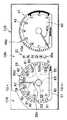
図1乃至図4は、本発明が自動車用コンビネーションメータに適用された例を示している。このコンビネーションメータは、当該自動車の車室内のインストルメントパネルに配設されており、当該コンビネーションメータは、図1及び図2にて示すごとく、計器板10並びに計器板10に配設した車速計20、インジケータ30及び回転計40を備えている。
【0038】
車速計20は、計器板10に形成された目盛り盤20aと、計器板10の裏面側にて目盛り盤20aに対応する位置に設けた回動内機20bとを備えている。目盛り盤20aは、計器板10の図1にて図示左側部に設けられている。なお、計器板10のうち目盛り盤20a及び後述するインジケータ部30a並びに目盛り盤40aを除く部分は黒色となっている。
【0039】
目盛り盤20aは、当該自動車の車速を表示する略円弧状目盛り文字部21を備えており、この目盛り文字部21の目盛り部や文字部は黒色となっている。なお、目盛り盤20aは、目盛り文字部21の目盛り部や文字部を除き光を透過するようになっている。
【0040】
回動内機20bは、交差コイル型駆動部22と、指針軸23とを備えており、指針軸23は、駆動部22から回路基板80の貫通穴部並びに後述する反射板70の反射板部72の下端開口部、導光板60の下端開口部61a及び計器板10(目盛り盤20a)の貫通穴部11を通り上方へ回動可能に延出している。但し、回動内機20bは、回路基板80、反射板70及び導光板60と共にケーシング90内に支持されている。なお、駆動部22は、入力に応じた電磁力に基づき指針軸23を回動する。また、ケーシング90は、計器板10にその裏面側から取り付けられている。
【0041】
また、車速計20は、発光指針20cを備えており、この発光指針20cは、指針本体24と、カバー25とを有している。指針本体24は、透明の導光樹脂材料により長手状に形成されており、この指針本体24は、その回動基部24aのボスにて、指針軸23の先端部に支持されている。この指針本体24の回動基部24aは、図2にて示すごとく、傾斜面24cを備えており、この傾斜面24cは反射面としての役割を果たす。カバー25は、指針本体24を被覆してなるもので、このカバー25は、指針本体24の指針部24bの上面に対応する上壁にてスリット25aを有している。
【0042】
これにより、発光指針20cにおいては、指針本体24の回動基部24a内にその下面から光が入射すると、この光は傾斜面24cにより反射されて指針部24b内に進む。これに伴い、指針部24b内の光はカバー25のスリット25aを通り出射する。このことは、指針部24bが、スリット25aからの出射光でもって光ることを意味する。なお、図2にて符号26はバランサを示す。
【0043】
導光板60は、計器板10にその裏面に沿い配設されており、この導光板60は、目盛り盤20aに対応する部分にて、断面八の字状の導光板部61を備えている。この導光板部61は、指針軸23と同心的に位置しており、この導光板部61は、指針軸23を包囲するように、目盛り盤20aの裏面から図2にて図示下方に向け末すぼまり状に延出している。なお、導光板60は、導光性樹脂材料により形成されている。
【0044】
反射板70は、導光板60にその裏面に沿い配設されており、この反射板70は、目盛り盤20aの円弧状目盛り文字部21に対応するように、環状の断面略八の字状反射板部71を備えている。この反射板部71の断面形状は、導光板60の裏面から図2にて図示下方に向け末すぼまり状に延出する形状となっている。
【0045】
また、反射板70は、断面八の字状の反射板部72を備えており、この反射板部72は、導光板60の導光板部61の裏面に沿い末すぼまり状に延出している。なお、反射板70の表面(導光板60側の面)は、白色印刷材料により印刷処理が施されている。
【0046】
また、環状拡散板70aが、図2にて示すごとく、反射板部71の上端側開口部71aにて、導光板60にその裏面に沿い配設されている。なお、この拡散板70aは拡散樹脂材料により形成されている。
【0047】
回路基板80は、ケーシング90内にて駆動部22上に沿い計器板10に平行に支持されており、この回路基板80の表面には、複数の光源81が、反射板70の環状反射板部71の下端開口部71b内に位置するように、この下端開口部71bの円周方向に沿い、間隔をおいて配設されている(図1参照)。これにより、各光源81は環状反射板部71内に発光する。以下、各光源81は透過用光源81という。
【0048】
また、複数の光源82は、導光板部61の下端開口部61aに対向するように、この下端開口部61aの円周方向に沿い間隔をおいて回路基板80の表面に配設されている(図1参照)。これにより、各光源82は、その発光により、導光板60の反射板部61内にその下端開口部61aから光を入射する。以下、各光源82を導光用光源82という。
【0049】
また、複数の光源83は、回路基板80の上面にて、発光指針20cの回動基部24aに対向するように、円周方向に間隔をおいて配設されている(図1参照)。これにより、各光源83は、その発光により、指針本体24bの回動基部にその下面から光を入射する。なお、各光源83は、以下、指針用光源83という。本第1実施形態では、指針用光源83、透過用光源81及び導光用光源82は、互いに異なる色にて発光する。また、光源83の数は、光源81、82の各数と共に必要に応じて変更してもよい。
【0050】
外側筒体84は、導光板60の導光板部61及び反射板70の環状反射板部72内にて、指針軸23と同軸的に位置するように、計器板10と回路基板80との間に挟持されている。一方、内側筒体85は、外側筒体84の内側にて、当該外側筒体84と同軸的に位置するように、回路基板80の表面に装着されており、この内側筒体85と外側筒体84との間には、各指針用光源83が位置している。なお、外側筒体84及び内側筒体85は、共に、遮光性樹脂材料により形成されている。
【0051】
また、回転計40も、車速計20と実質的に同様に構成されている。この回転計40は、計器板10に形成した目盛り盤40aと、計器板10の裏面側に配設した回動内機40b(図3参照)を有しており、目盛り盤40aは、当該自動車のエンジンの回転数を表す表示パターン部41を備えている。
【0052】
インジケータ30は、計器板10に形成したインジケータ部30aを備えている。なお、図1及び図2において、各符号100及び110は、環状の見返し板及び湾曲状フロントパネルをそれぞれ示す。
【0053】
また、コンビネーションメータは、図3にて示すごとく、車速センサ120、回転数センサ130及びマイクロコンピュータ140を備えている。車速センサ120は、当該自動車の車速を検出する。回転数センサ130は、当該自動車のエンジンの回転数を検出する。
【0054】
マイクロコンピュータ140は、図4にて示すフローチャートに従い、コンピュータプログラムを実行し、この実行中において、車速センサ120及び回転数センサ130の各検出出力に基づく各回動内機20b、40bの作動及び各光源81乃至83の点消灯のための演算処理をする。なお、上記コンピュータプログラムはマイクロコンピュータ140のROMに予め記憶されている。また、マイクロコンピュータ140は、当該自動車に搭載のバッテリBから直接給電されて作動している。また、図3にて符号IGは、当該自動車のイグニッションスイッチを示す。
【0055】
このように構成した本第1実施形態において、マイクロコンピュータ140が図4のフローチャートに従いステップ200にてNOとの判定を繰り返している間に、当該自動車が、イグニッションスイッチIGのオンにより、走行状態におかれるものとする。
【0056】
すると、マイクロコンピュータ140は、ステップ200において、YESとの判定処理をする。ついで、ステップ210において、当該自動車の車速及びエンジンの回転数が、車速センサ120及び回転数センサ130の各検出出力に基づき、出力処理される。
【0057】
これに伴い、車速計20が、その回動内機20bの作動に応じて、発光指針20cを回動し、また、回転計40が、その回動内機40bの作動に応じて発光指針40cを回動する。これにより、発光指針20cは車速を目盛り盤20aの表面にて指示し、発光指針40cは、エンジンの回転数を目盛り盤40aの表面にて指示する。
【0058】
ステップ210の処理後、ステップ220において、車速計20の各指針用光源83及び回転計40の各指針用光源の点灯処理がなされる。これにより、車速計20の各指針用光源83及び回転計40の各指針用光源が共に点灯する。
【0059】
これに伴い、車速計20においては、各指針用光源83からの光が発光指針20cの指針本体24内にその回動基部24aから入射する。すると、各指針用光源83からの入射光は、指針本体24内にて傾斜面24cにより反射されて指針部24b内に進行する。然る後、指針部24b内の光は、カバー25のスリット25aから出射する。なお、このようなことは回転計40においても同様である。
【0060】
ステップ220の処理後、ステップ221において、所定の遅延時間(例えば、1秒)の経過の有無が判定される。この判定は、マイクロコンピュータ140に内蔵のタイマーによるステップ220の処理後の計時時間と上記遅延時間との比較でなされる。なお、上記タイマーは、ステップ220の処理の終了と同時にリセットされて計時を開始する。
【0061】
その後、上記タイマーの計時時間が上記所定の遅延時間に達すると、ステップ221における判定がYESとなると、ステップ230において、車速計20の各透過用光源81及び各導光用光源82並びに回転計40の各透過用光源及び各導光用光源の点灯処理がなされる。
【0062】
これにより、車速計20の各透過用光源81及び各導光用光源82並びに回転計40の各透過用光源及び各導光用光源が共に点灯する。これに伴い、各透過用光源81の光は、反射板70の反射板部71の内面で反射された後、拡散板70aにより拡散されて均一な拡散光として目盛り盤20aを透過する。回転計40においても、車速計20の場合と同様である。
【0063】
ステップ230の処理後、イグニッションスイッチIGのオフの有無が判定される。現段階にてイグニッションスイッチIGがオンのままならば、ステップ240における判定がNOとなり、ステップ200乃至ステップ230の処理が繰り返される。
【0064】
一方、ステップ240における判定がYESとなる場合には、ステップ250において、車速及び回転数の出力処理が停止されるとともに、上記各光源の消灯処理がなされる。これに伴い、各発光指針20b、40bによる指示が停止されるとともに、車速計20及び回転計40の各光源が消灯する。
【0065】
以上説明したように、イグニッションスイッチIGのオンを前提として、車速計20及び回転計40の各指針用光源の点灯後上記遅延時間の経過時に車速計20及び回転計40の各透過用光源及び導光用光源を点灯するようにした。これにより、車速計20においては、イグニッションスイッチIGのオンを前提として、発光指針20bがそのスリット25aにて発光した後、上記遅延時間の経過時に目盛り盤20aが発光する。
【0066】
その結果、上述のような遅延時間を介する時差点灯により、斬新な視認性を確保できる。この場合、目盛り盤20aの色が透過用光源及び導光用光源の発光色の合成色となり、指針用光源の発光色とは異なるため、発光指針の発光色と目盛り盤の色とは異なるため、より一層斬新な視認性を向上できる。また、外側筒体84により各指針用光源83を遮光しているから、これら光源83の光が透過用及び導光用の各光源81、82側へ漏洩することがない。以上のような作用効果は、回転計40においても同様に得られる。
【0067】
なお、上記第1実施形態では、各ステップ220乃至230での処理により、指針用光源83の点灯処理後、所定の遅延時間の経過時に透過用光源81及び導光用光源82を点灯処理するようにしたが、これに代えて、透過用光源81及び導光用光源82の点灯処理後、所定の遅延時間の経過時に指針用光源83の点灯処理をしてもよい。
【0068】
この場合には、透過用光源81及び導光用光源82の点灯のもと所定の遅延時間の経過時に指針用光源83を点灯することとなり、その結果、上記第1実施形態と実質的に同様の作用効果を達成できる。また、指針用、透過用及び導光用の各光源の発光色は、共に同一であっても、上記遅延時間を介する時間差点灯でもって、斬新な視認性を確保できる。
(第2実施形態)
次に、本発明の第2実施形態を図5及び図6に基づいて説明する。この第2実施形態では、当該自動車に搭載の自動点灯器150が、上記第1実施形態にて述べたマイクロコンピュータ140に付加的に接続されている。当該自動車の走行環境が夜間になると、自動点灯器150は、その光量センサにより、光量の減少を検出し、当該自動車のスモールランプ等のランプを点灯すると共に、光センサの検出出力をマイクロコンピュータ140に出力する。
【0069】
また、本第2実施形態では、上記第1実施形態にて述べた各透過用光源81の発光色は、オレンジ色であり、かつ、各導光用光源82の発光色は白色である。また、マイクロコンピュータ140は、上記第1実施形態にて述べたフローチャートに代えて、図6にて示すフローチャートに従い、コンピュータプログラムを実行する。その他の構成は上記第1実施形態と同様である。
【0070】
このように構成した本第2実施形態において、マイクロコンピュータ140が、上記第1実施形態と同様にステップ210における処理を終了すると、次のステップ260において、当該自動車の走行環境が夜間か否かが判定される。ここで、当該自動車が夜間走行中であれば、ステップ260において、自動点灯器150の光センサの検出出力に基づきYESとの判定がなされる。
【0071】
すると、ステップ261において、車速計20及び回転計40の各指針用光源の点灯処理がなされる。このため、当該各指針用光源が点灯し、これに伴い、両発光指針20c、40cが共に各スリットにて発光する。
【0072】
ステップ261の処理後、ステップ262において、車速計20及び回転計40の各導光用光源の点灯処理がなされる。このため、当該各導光用光源が点灯しこれに伴い、各目盛り盤20a、40aが、導光板60からの光を入射されて発光する。
【0073】
一方、当該自動車の走行環境が昼間であるために、自動点灯器150の光量センサの検出出力に基づきステップ260における判定がNOとなると、ステップ263において、車速計20及び回転計40の各透過用光源の点灯処理がなされる。このため、当該各透過用光源が点灯し、これに伴い、各目盛り盤20a、40aが発光する。
【0074】
以上説明したように、本第2実施形態では、当該自動車の走行環境が夜間のときには車速計20及び回転計40の各指針用光源及び各導光用光源を点灯し、また、当該自動車の走行環境が昼間のときには車速計20及び回転計40の各透過用光源を点灯するようにした。
【0075】
これにより、夜間には、両目盛り盤20a、40aが白色で発光し、昼間には、両目盛り盤20a,40aがオレンジ色で発光する。その結果、このような両目盛り盤20a、40aの表示色の昼夜切り換えにより、斬新な視認性を確保できる。
【0076】
なお、上記第2実施形態では、ステップ260における判定を夜間か否かで行う例について説明したが、これに代えて、当該自動車の周囲が夜間と同様に暗いか否かでステップ260における判定を行うようにしてもよい。これにより、当該自動車の走行環境が、夜間か否かに限ることなく、例えば、トンネル内か否かでもって、ステップ260での判定がなされることになる。従って、当該自動車がトンネル内か否かでもって、上記第2実施形態と同様のマイクロコンピュータ140による処理のもと、当該第2実施形態と同様の作用効果を達成できる。
【0077】
また、上記第2実施形態では、各透過用光源81の発光色をオレンジ色としたが、これに限らず、各透過用光源81の発光色を自然光とし、拡散板70aをオレンジ色の拡散樹脂材料で形成するか、或いはオレンジ色に着色するようにしてもよい。
【0078】
また、上記第2実施形態では、各透過用光源81の発光色をオレンジ色とし、かつ、各導光用光源82の発光色を白色としたが、これに限らず、各透過用光源81の発光色を白色とし、かつ、各導光用光源82の発光色をオレンジ色としてもよい。
【0079】
また、上記第2実施形態では、ステップ260における判定を自動点灯器150の光センサの出力でもって行うようにしたが、これに代えて、スモールランプ等Lの点灯出力でもってステップ260での判定を行うようにしてもよい。
(第3実施形態)
図7及び図8は、本発明の第3実施形態を示している。この第3実施形態では、図7にて示すごとく、上記第2実施形態において、可変抵抗器160が、上記第2実施形態にて述べたマイクロコンピュータ140に付加的に接続された構成が採用されている。
【0080】
この可変抵抗器160は、車速計20及び回転計40の各導光用光源の光量を調整するために用いられる。ここで、当該可変抵抗器160は、その抵抗値にて、当該自動車の乗員の好み応じ調整されて、この調整抵抗値をマイクロコンピュータ140に入力する。但し、本第3実施形態では、当該可変抵抗器160の抵抗値と各導光用光源の光量とは逆比例するようになっている。
【0081】
また、本第3実施形態では、車速計20及び回転計40の各導光用光源の発光色は緑色であり、各透過用光源の発光色はオレンジ色である。また、本第3実施形態では、上記第2実施形態にて述べたマイクロコンピュータ140が、図6のフローチャートに代えて、図8にて示すフローチャートに従いコンピュータプログラムを実行するように変更されている。その他の構成は上記第2実施形態と同様である。
【0082】
このように構成した本第3実施形態において、上記第2実施形態にて述べたと同様にステップ261における処理のもと車速計20及び回転計40の各指針用光源が点灯された後、ステップ264において、車速計20及び回転計40の各導光用光源及び各透過用光源の点灯処理がなされる。
【0083】
このため、車速計20及び回転計40の各導光用光源及び各透過用光源が点灯する。ついで、ステップ265において、可変抵抗器160からその抵抗値が入力されて各導光用光源の光量の調整処理がなされる。このため、当該各導光用光源の光量は、可変抵抗器160の抵抗値に応じた光量になる。
【0084】
ここで、可変抵抗器160の抵抗値が最小値になっていれば、例えば、車速計20において、各導光用光源82の光量が最大となる。このため、各導光用光源82の緑色が各透過用光源81がオレンジ色に合成されるので、目盛り盤20aの発光色は黄色になる。
【0085】
また、可変抵抗器160の抵抗値を最大にすれば、各導光用光源82の光量が最小となる。このため、各導光用光源82の緑色に比べて各透過用光源81のオレンジ色が著しく優勢となり、目盛り盤20aの発光色は実質的にオレンジ色になる。
【0086】
このように、乗員による可変抵抗器160の抵抗値の好みに応じた調整により目盛り盤20aの発光色をオレンジ色と黄色との間で調整できる。このようなことは、回転計40においても同様に実現される。よって、上述した斬新な視認性をより一層向上できる。
【0087】
なお、上記第3実施形態では、各導光用光源の光量を調整するために可変抵抗器160を用いる例について説明したが、これに限らず、各透過用光源の光量を調整する可変抵抗器をさらに採用し、この可変抵抗器の抵抗値をも調整するようにすれば、目盛り盤の発光色を黄色を介しオレンジ色と緑色との間で調整できる。これにより、乗員の好みに応じた目盛り盤の発光色の変化範囲が上記第3実施形態に比べてさらに広げられ得る。
【0088】
また、本発明の実施にあたり、上記第3実施形態にて述べた場合と異なり、ステップ260におけるNOとの判定に基づき両ステップ264、265の処理をし、一方、ステップ260におけるYESとの判定に基づき両ステップ261、263の処理を行うようにしてもよい。
【0089】
また、本発明の実施にあたり、上記第3実施形態に代えて、上記第1実施形態において可変抵抗器160をマイクロコンピュータ140に接続し、かつ各透過用光源の発光色をオレンジ色にするとともに各導光用光源の発光色を緑色にして、ステップ230(図4参照)における各透過用光源及び各導光用光源の点灯処理のもと、可変抵抗器160の抵抗値を調整すれば、上記第3実施形態と同様に目盛り盤の発光色を調整できる。
(第4実施形態)
図9及び図10は、本発明の第4実施形態を示している。この第4実施形態では、計器板10A、導光板60A、導光部材170、リフレクタ180及び環状拡散板180aが、上記第2実施形態にて述べた計器板10、導光板60、外側筒体84、内側筒体85、リフレクタ70及び環状拡散板70aに代えて採用されている。
【0090】
計器板10Aは、上記第2実施形態にて述べた各目盛り盤20a及び40aにそれぞれ対応する各目盛り盤20d及び40dを備えており、目盛り盤20dは、略円板状中央部27と、略円環状外周部28とに分離して構成されている。略円環状外周部28は、略円板状中央部27の外周に沿い同心的に位置しており、略円環状外周部28は、図10にて示すごとく、その内周縁28aにて、略円板状中央部27の外周縁27aの裏面側に位置している。また、略円環状外周部28は、その内周縁28aから外周縁28bにかけて略円板状中央部27の表面側へ延出するように、断面傾斜状に形成されている。なお、計器板10Aはその外周部にて上記第2実施形態にて述べた見返し板100の底壁101の内端部裏面に装着されている。
【0091】
ここで、略円環状外周部28は、上記第2実施形態にて述べた目盛り盤20aの目盛り文字部21のうち目盛りに相当し、以下、目盛り部28という。また、略円板状中央部27の外周部は、目盛り盤20aの目盛り文字部21のうち文字を表す部分に相当し、以下、文字部27aという。なお、略円板状中央部27のうち文字部27a以外の部分は目盛り盤20aのうち目盛り文字部21を除く部分と同様である。
【0092】
目盛り盤40dは、目盛り盤20dと実質的に同様の構成からなるもので、この目盛り盤40dは、目盛り盤20dの略円板状中央部27及び略円環状外周部28にそれぞれ対応する略円板状中央部42及び略円環状外周部43を備えている。略円環状外周部43は、目盛り盤40aの目盛り文字部のうちの目盛り部に相当し、略円板状中央部42の外周部42aは目盛り盤40aの目盛り文字部のうちの文字部に相当する。
【0093】
導光板60Aは、計器板10Aにその裏面に沿い配設されており、この導光板60Aは、その開口部62にて、指針軸23を挿通させるように略同心的に位置している。ここで、開口部62は円弧状導光板部63を備えており、この円弧状導光板部63は、図10にて目盛り盤10dの裏面から図示下方に向けて、上に凸な断面湾曲形状にて指針軸23側に向け延出している。なお、当該円弧状導光板部63は、その下端部63aにて、上記第1実施形態にて述べた各導光用光源82に対向している。
【0094】
また、導光板60Aは、図10にて示すごとく、略円板状中央部27の外周縁27aの裏面側にて、略円状出射端面64を備えており、この略円状出射端面64は、略円環状目盛り部28の表面に対向している。なお、導光板60Aのうち目盛り盤40dに対応する部分も、目盛り盤20dに対応する部分と同様に形成されている。また、導光板60Aは、導光性樹脂材料により形成されている。
【0095】
リフレクタ180は、図10にて示すごとく、環状枠181を備えており、この環状枠181は、見返し板100の底壁101とケーシング90の開口部との間にて回路基板80の外周部を介しねじ91の締着によりケーシング90の開口部に挟持されている。これにより、リフレクタ180は見返し板100とケーシング90との間に回路基板80を介し挟持されている。
【0096】
また、リフレクタ180は、環状枠181の上壁を構成する反射板182を備えている。この反射板182は、断面八の字状の反射板部183を備えており、この反射板部183は、導光板60Aの裏面側から下方に向け末すぼまり状に延出している。ここで、反射板部183は、目盛り盤20dのうち発光指針20cの回動範囲に対応する導光板60Aの裏面に沿い、円弧状に形成されており、この反射板部183の円環状下端開口部183a内には、その周方向に沿い、上記第2実施形態にて述べた各透過用光源81が位置している。
【0097】
また、リフレクタ180は、略円環状反射板部186を備えており、この略円環状反射板部186は、図10にて示すごとく、略円環状導光部63に対応して略同心的に位置し、リフレクタ180のうち反射板部183の内周部から各導光用光源82に向け傾斜状に延出している。これにより、この反射板部186は各導光用光源82の光を導光部63の外周面に向け反射する役割を果たす。
【0098】
また、反射板182は、導光板60Aの開口部62に対応する位置にて、外側筒体184を備えており、この外側筒体184は、目盛り盤20dの開口部の外周部とこれに対向する回路基板80の部分との間に挟持されている。また、反射板182は、内側筒体185を備えており、この内側筒体185は、外側筒体184内にて指針軸23と同心的に位置して、外側筒体184の環状低壁184aの内周部から立ち上がっている。なお、反射板部183の表面、外側筒体184の内面及び内側筒体185の外周面を含め、反射板182の表面は白色印刷材料により印刷処理が施されている。
【0099】
環状拡散板180aは、反射板部183の上端側開口部183bにて、導光板60Aにその裏面に沿い配設されている。なお、この拡散板180aは拡散樹脂材料により形成されている。
【0100】
導光部材170は、図10にて示すごとく、導光材料により形成した筒体からなるもので、この導光部材170は、両筒体184、185間に収容組み付けされている。導光部材170は、筒状部材本体171と、この部材本体171の上端外周部から半径方向に外方に向け突出する環状フランジ172とにより構成されている。これにより、導光部材170では、部材本体171が両筒体184、185間に位置し、フランジ172が目盛り盤20dの開口部の外周部上に着座係合している。
【0101】
また、部材本体171は、その内周面から複数の突起171aを突出させてなるもので、この部材本体171の各突起171aは、内側筒体185の各係合孔部185a内にそれぞれ係合している。これら各係合は、フランジ172でもって目盛り盤20dの開口部の外周部を外側筒体184の周壁の上端部に押さえ付けるようになされている。
【0102】
また、部材本体171は、三つの凸レンズ部171b(図10では二つの凸レンズ部のみを示す)を備えており、これら各凸レンズ部171bは、部材本体171の環状底面(光源側環状端面)から下方にむけ凸レンズ形状に隆起形成されている。ここで、各凸レンズ171bは、各指針用光源83にそれぞれ対向して位置している。これにより、導光部材170は、各指針用光源83の光を、これら各光源83にそれぞれ対向する各凸レンズ部171bにて、受光して並行光に変換して内部に導光し、上面から発光指針20cの回動基部24aの裏面に向けて出射する。但し、本実施形態では、各導光用光源82はその点灯により青色にて発光し、また、各透過用光源81はその点灯により白色にて発光する。なお、回転計40も、車速計20と実質的に同様に構成されている。その他の構成は上記第2実施形態と同様である。
【0103】
このように構成した本第4実施形態において、上記第2実施形態と同様に、当該自動車の走行環境が夜間のとき車速計20の各指針用光源83及び各導光用光源82を点灯すると、各光源83の光は、導光部材170により、対応の各凸レンズ部171bにてそれぞれ並行光に変換して部材本体171の内部に導入する。これに伴い、部材本体171内の各並行光は当該部材本体171の上端面から発光指針20cの回動基部24a内に入射する。
【0104】
この場合、各光源83の光が、上述のごとく、導光部材170によりその各凸レンズ部171bの光学的作用のもと、並行光として回動基部24aに入射するので、この各入射光は、各光源83の間の領域にて暗くなることなく、各光源83の光に対応して、均一な光として効率よく回動基部24a内に入射し得る。
【0105】
このため、発光指針20cは、その回動位置にかかわらず、回動基部24a内に入射した光に基づき、均一な輝度にて指針部20cにてカバー25のスリット25aを通して発光し得る。なお、上述のごとく、各筒体184、185は各光源83の光を導光部材170に向けて反射するから、各光源82の光の利用率をより一層高め得る。
【0106】
また、各導光用光源82の青色の光は、導光板60A内にその導光部63から入射して導光され出射端面64から目盛り部28に向けて出射する。このため、目盛り部28は青色光で照明される。このとき、導光部63により導光された青色光は目盛り盤20dの略円板状中央部27にその裏面から入射する。これに伴い、略円板状中央部27の文字部27aは、目盛り部28の表面よりも暗い青色で光る。その結果、発光指針20cによる指示が目盛り部28が文字部27aよりも明るい青色で照明されている状態にて発光指針20cによる指示が視認され得る。また、文字部27aは上述のごとく断面傾斜状に形成されている。このため、導光板60Aの出射端面64から目盛り部28の表面に出射する青色光のもと、夜間における発光指針20cによる指示が奥行き感のある立体感をもって斬新な視認性にて提供され得る。
【0107】
また、上記第2実施形態と同様に当該自動車の走行環境が昼間のとき車速計20の各透過用光源81が点灯すると、これら各光源81の白色光が反射板部183により反射されるとともに拡散板180aにより拡散されて目盛り盤20dをその裏面から透過する。このとき、目盛り盤20dのうち中央部27と目盛り部28との間の空隙を通る光の輝度が中央部27及び目盛り部28を通る光の輝度よりも高いので、上記空隙の部分が環状にて明るく光る。また、上述のように、文字部27aは断面傾斜状に形成されている。これにより、拡散板180aからの出射白色光のもと、昼間における発光指針20cによる指示が奥行き感のある立体感をもって斬新な視認性にて提供され得る。なお、以上の作用効果は回転計40でも同様に達成できる。
【0108】
また、上述のような当該自動車の夜間走行において、各導光用光源82に加え各透過用光源81をも点灯させれば、導光板60Aの出射端面64からの青色の出射光と拡散板180aからの白色の出射光の双方が目盛り部28の表面を照明する。このため、夜間における発光指針20cによる指示が暗白色のもと奥行き感のある立体感をもって斬新な視認性にて提供され得る。
(第5実施形態)
図11は本発明の第5実施形態を示している。この第5実施形態では、上記第4実施形態にて述べた目盛り盤20dにおいて略円環状目盛り部28が略円板状中央部27と一体化されている。また、本第5実施形態では、上記第4実施形態にて述べた拡散板180aが廃止されて、導光板60Aが当該拡散板180aに代えてリフレクタ130の反射板部183の上端側開口部183bを覆うように延長されている。
【0109】
また、略円環板状導光部材190が、図11にて示すごとく、リフレクタ180の外周に形成した壁部186に沿い配設されており、この導光部材190は、そのL字状屈曲部191にて、壁部186の上端と見返し板100の底壁101の内端部との間から目盛り盤20dの表面側を臨むように位置している。また、上記第4実施形態にて述べた各導光用光源82は、導光部材190の下端面192に対向するように、回路基板80の表面に設けられている。但し、本第5実施形態では、上記第4実施形態とは異なり、各導光用光源82はその点灯により白色にて発光し、また、各透過用光源81はその点灯により青色にて発光する。その他の構成は上記第4実施形態と同様である。
【0110】
このように構成した本第5実施形態によれば、上記第4実施形態と同様に、各指針用光源83による発光指針20cの指示のもと、各透過用光源81又は各導光用光源82の点灯或いはこれら各光源81、82の同時点灯により、各光源の青色光、各光源82の白色光或いはこれらの混合による青暗色光により、目盛り盤20dの目盛り部28の断面傾斜形状と相まって、上記第4実施形態と同様に奥行き感のある立体感でもって斬新な視認性を提供できる。
【0111】
ここで、導光部材190は、各光源82の白色光を入射されて屈曲部191から目盛り盤20dの表面に沿い出射するので、上記第4実施形態にて述べた各光源82の光とは異なる斬新な目盛り盤20dの照明感覚を確保できる。なお、以上の作用効果は回転計40でも同様である。
【0112】
なお、本発明の実施にあたり、上記第5実施形態にて述べた目盛り盤20dは、上記第4実施形態と同様に中央部27と、外周部28とに分離していてもよい。これにより、各透過用光源81の光が、中央部27と外周部28との間隙をも通るので、上記第4実施形態にて述べたと実質的に同様の作用効果を達成できる。
【0113】
また、本発明の実施にあたり、上記第5実施形態にて述べた導光部材190は、導光板60Aが導光部として一体に有するものであってもよい。
【0114】
また、本発明の実施にあたっては、ステップモータを駆動源とする指示計器や交差コイル型指示計器に限ることなく、可動コイル型指示計器や可動鉄心型指示計器のように、回動する指針軸を有する指示計器や各種の計器に本発明を適用して実施しても、上記各実施形態と同様の作用効果を達成できる。
【0115】
また、本発明の実施にあたり、コンビネーションメータに限ることなく、車速計単独の計器や回転計単独の計器に本発明を適用して実施してもよい。
【0116】
また、本発明の実施にあたり、各指針用光源を廃止するとともに、発光指針に代えて、通常の指針を採用して実施してもよい。
【0117】
また、本発明の実施にあたり、上記各実施形態にて述べた各光源は、ランプに限ることなく、たとえば、発光ダイオード、冷陰極管、エレクトロルミネッセンス素子等の発光素子でもよい。
【0118】
また、上記各実施形態では、各指針用光源83を回路基板80の表面に設けた例について説明したが、これに代えて、各指針用光源83として、例えば、単一の発光ダイオードを採用し、この発光ダイオードを指針本体24の回動基部24c内に設けるようにしても、上記各実施形態と同様の作用効果を達成できる。
【0119】
また、本発明の実施にあたり、イグニッションスイッチIGに代えてキースイッチを有する電気自動車の計器に本発明を適用して実施してもよい。また、自動車に限ることなく、トラック、バス車両や自動二輪車等の各種車両用計器に本発明を適用してもよい。
【図面の簡単な説明】
【図1】本発明の第1実施形態を示す部分的破断正面図である。
【図2】図1にて2−2線に沿う断面図である。
【図3】上記第1実施形態の回路構成図である。
【図4】図3のマイクロコンピュータの作用を示すフローチャートである。
【図5】本発明の第2実施形態を示す回路構成図である。
【図6】図5のマイクロコンピュータの作用を示すフローチャートである。
【図7】本発明の第3実施形態を示す回路構成図である。
【図8】図7のマイクロコンピュータの作用を示すフローチャートである。
【図9】本発明の第4実施形態を示す部分的破断正面図である。
【図10】図9にて10−10線に沿う断面図である。
【図11】本発明の第5実施形態を示す破断図である。
【符号の説明】
10…計器板、20a、20d、40a、40d…目盛り盤、
20b、40b…回動内機、20c、40c…発光指針、
21、41…目盛り文字部、23…指針軸、27…略円板状中央部、
27a…文字部、28…略環状外周部、60、60A…導光板、
81、82、83…光源、84…外側筒体、140…マイクロコンピュータ、
150…自動点灯器、160…可変抵抗器、190…導光部材、
IG…イグニッションスイッチ。[0001]
BACKGROUND OF THE INVENTION
The present invention relates to various instruments such as an indicating instrument mounted on a vehicle.
[0002]
[Prior art]
Conventionally, for example, there is a vehicle indicating instrument as shown in Japanese Patent Laid-Open No. 9-21655. In this indicating instrument, a printed circuit board is interposed between the scale plate and the rotating inner unit located on the back side thereof, and light is incident on both the scale plate and the pointer on the surface of the printed circuit board. A light source is provided.
[0003]
[Problems to be solved by the invention]
However, as described above, since the light is incident on the scale plate and the pointer with the same light source as described above, the display mode of the scale plate and the pointer is naturally uniform and interesting. It has never been.
[0004]
In view of the above, the present invention provides a vehicular instrument in which a novel and interesting visibility is ensured by adjusting the incident time and color of light on a scale plate and the like in order to cope with such a situation. For the purpose.
[0008]
[Means for Solving the Problems]
In solving the above issues,Claim1The vehicle instrument according to the invention described in
A light-transmitting scale plate (20a, 40a, 20d, 40d);
A light guide plate (60) provided along the back surface of the dial plate;
A rotary inner unit (20b, 40b) having a pointer shaft (23) provided on the back side of the light guide plate and rotatably extending through the through holes (11, 61a) of the light guide plate and the scale plate. When,
Luminous pointers (20c, 40c) supported by a rotation base (24c) at the tip of the pointer shaft so as to rotate along the surface of the dial;
A light source for transmission (81) that transmits light by emitting light from the back side of the scale plate through the light guide plate in the thickness direction;
A light source for light guide (82) disposed inside the light source for transmission on the back surface side of the light guide plate and allowing light to enter the light guide plate from the through hole portion by light emission;
A pointer light source (83) that is disposed inside the light guide light source on the back surface side of the light guide plate, and causes light to enter the light emitting pointer through the through holes of the light guide plate and the scale plate from the rotating base portion by light emission. When,
When the vehicle key switch (IG) is turned on, control is performed so that at least one of both the light source for transmission and the light source for light transmission and the light source for pointers emits light. Control means (220, 221, 230) for controlling at least one of the light sources for both transmission and light guide and the other of the light sources for pointers to emit light.
[0009]
As a result, on the premise that the key switch is turned on, after illuminating one of the scale plate and the light emission indicator by light emission of at least one of the light sources for both transmission and light guide and the light source for pointer, the delay time is increased. During the lapse of time, the other of the scale plate and the light emitting pointer is caused to emit light by light emission of at least one of the light sources for both transmission and light guide and the light source for pointer.
[0010]
As a result, even when a light guide plate is used, a novel and interesting visibility is realized by the time difference light emission of one of the scale plate and the light emission pointer through the delay time on the premise that the key switch is turned on as described above. It can be secured.
[0011]
Claims3The vehicle instrument according to the invention described in
A light-transmitting scale plate (20a, 40a, 20d, 40d);
A light guide plate (60, 60A) provided along the back surface of the scale plate;
A rotary inner unit (20b, 40b) having a pointer shaft (23) provided on the back side of the light guide plate and rotatably extending through the through holes (11, 61a) of the light guide plate and the scale plate. When,
A pointer (20c) supported by a rotation base (24c) at the tip of the pointer shaft so as to rotate along the surface of the dial;
A light source for transmission (81) that transmits light by emitting light from the back side of the scale plate through the light guide plate in the thickness direction;
A light source for light guide (82) disposed inside the light source for transmission on the back surface side of the light guide plate and allowing light to enter the light guide plate from the through hole portion by light emission;
Brightness detection means (150) for detecting brightness around the vehicle;
Control means (260, 262, 263) for controlling one or the other of the light sources for transmission and light guide to emit light according to the brightness detected by the brightness detection means.
[0012]
Thus, for example, when the surroundings of the vehicle are dark at night or in a tunnel, one of the light sources for both transmission and light guide is emitted, and when the surroundings of the vehicle are bright in the daytime, If the other one of the light sources for both transmission and light guide is illuminated, the scale plate also shines according to the difference in light quantity between the light source for transmission and the light source for light guide via the light guide plate.
[0013]
As a result, a novel and interesting visibility can be secured by switching the light intensity of the scale plate due to the difference in brightness around the vehicle.
[0014]
Claims5The vehicle instrument according to the invention described in
A light-transmitting scale plate (20a, 40a, 20d, 40d);
A light guide plate (60, 60A) provided along the back surface of the scale plate;
A rotary inner unit (20b, 40b) having a pointer shaft (23) provided on the back side of the light guide plate and rotatably extending through the through holes (11, 61a) of the light guide plate and the scale plate. When,
Luminous pointers (20c, 40c) supported by a rotation base (24c) at the tip of the pointer shaft so as to rotate along the surface of the dial;
A light source for transmission (81) that transmits light by emitting light from the back side of the scale plate through the light guide plate in the thickness direction;
A light guide light source (82) that is disposed inside the light source for transmission on the back side of the light guide plate and makes light of a color different from that of the light source for transmission incident on the light guide plate from the through hole portion;
A pointer light source (83) that is disposed inside the light guide light source on the back surface side of the light guide plate, and causes light to enter the light emitting pointer through the through holes of the light guide plate and the scale plate from the rotating base portion by light emission. When,
When the key switch (IG) of the vehicle is turned on, control is performed so that one of the light source for both transmission and light guide and the light source for pointer is made to emit light. Control means (220, 221, 230) for controlling the other light source and the other of the pointer light source to emit light;
A light amount adjusting means (160) for adjusting the light amounts of at least one of the light sources for transmission and light guide so as to be different from each other;
[0015]
As a result, on the premise that the key switch is turned on, after one of the scale plate and the light emission indicator is lit by one light emission of both the light source for transmission and the light guide and the light source for pointer, The other of the scale plate and the light emission indicator is caused to shine by the other light emission of both the light guide light sources and the pointer light source.
[0016]
In addition, since the light amounts of at least one of the light sources for transmission and light guide are adjusted to be different from each other, the combined color of both light sources changes according to the adjustment of the light amount.
[0017]
As a result, in addition to the time difference light emission of one and the other of the scale plate and the light emission indicator through the delay time on the premise that the key switch is turned on as described above, the color that the scale plate shines changes with the composite color, Visible and innovative visibility that suits the passenger's preference.
[0018]
Claims7The vehicle instrument according to the invention described in
A light-transmitting scale plate (20a, 40a, 20d, 40d);
A light guide plate (60, 60A) provided along the back surface of the scale plate;
A rotary inner unit (20b, 40b) having a pointer shaft (23) provided on the back side of the light guide plate and rotatably extending through the through holes (11, 61a) of the light guide plate and the scale plate. When,
A pointer (20c) supported by a rotation base (24c) at the tip of the pointer shaft so as to rotate along the surface of the dial;
A light source for transmission (81) that transmits light by emitting light from the back side of the scale plate through the light guide plate in the thickness direction;
A light guide light source (82) that is disposed inside the light source for transmission on the back side of the light guide plate and makes light of a color different from that of the light source for transmission incident on the light guide plate from the through hole portion;
Brightness detection means (150) for detecting brightness around the vehicle;
Control means (260, 263, 264) for controlling one or the other of the light sources for both transmission and light guide to emit light according to the detected brightness of the brightness detection means;
Light amount adjusting means (160, 265) for adjusting at least one light amount of the light sources for both transmission and light guide so as to be different from each other;
[0019]
As a result, the claim5Even if the pointer is not a light emission guide as in the invention described in claim 1,5The effect substantially the same as that of invention described in 1 can be achieved.
[0020]
Claims9The vehicle instrument according to the invention described in
A light-transmitting scale plate (20a, 40a, 20d, 40d);
A light guide plate (60, 60A) provided along the back surface of the scale plate;
A rotary inner unit (20b, 40b) having a pointer shaft (23) provided on the back side of the light guide plate and rotatably extending through the through holes (11, 61a) of the light guide plate and the scale plate. When,
Pointers (20c, 40c) supported by a rotation base (24c) at the tip of the pointer shaft so as to rotate along the surface of the dial;
A light source for transmission (81) that transmits light by emitting light from the back side of the scale plate through the light guide plate in the thickness direction;
A light guide light source (82) disposed inside the light source for transmission on the back side of the light guide plate and allowing light of a color different from that of the light source for transmission to enter the light guide plate from the through hole portion. .
[0021]
In this way, a transmission light source that emits light of different colors and a light source for light guide are provided separately, and light from the light source for transmission is transmitted through the scale plate through the light guide plate in the plate thickness direction. Even if light is guided from the through-hole portion into the light guide plate and transmitted through the scale plate, interesting and novel visibility can be obtained.
[0022]
In addition, each claim2,4According to the invention described in each claim1,3In these inventions, unlike these inventions, the light source for light guide is a light source for light guide that is disposed outside the light source for transmission on the back side of the light guide plate and emits light toward the light guide plate side. The light guide plate has a light guide part (190) that guides the light of the light source for light guide at the outer peripheral part and emits the light from the outer peripheral side on the surface of the scale plate.
[0023]
This also means that each claim1,3The effect substantially the same as that of invention described in 1 can be achieved.
[0024]
In addition, each claim6,810According to the invention described in each claim5,7,9In these inventions, unlike these inventions, the light guide light source is disposed outside the transmission light source on the back side of the light guide plate and has a different color from the transmission light source toward the light guide plate side. A light guide light source that emits light, and the light guide plate has a light guide part (190) that guides light of the light source for light guide at the outer peripheral part and emits the light from the outer peripheral side to the surface of the scale plate. Have.
[0025]
This also means that each claim5,7,9The effect substantially the same as that of invention described in 1 can be achieved.
[0026]
Claim 11According to the invention described in claim9Or 10In the vehicle instrument described in
The pointer is a light emission guide,
Both the light source for transmission and light guide by light emission from the rotation base into the light emitting pointer through the through hole portions of the light guide plate and the scale plate on the back side of the light guide plate Includes a pointer light source (83) for allowing light of different colors to enter.
[0027]
As a result, the claim9Or 10The effects of the invention described in 1) can be further improved.
[0028]
Claim 12According to the invention described in claim 1 to 11In the vehicular instrument according to any one of the above, a circuit board that is provided in parallel with the scale plate between the scale plate and the rotating inner unit and includes each of the light sources so as to face the scale plate ( 80).
[0029]
Accordingly, the structure of the instrument is further simplified, and claims 1 to 1 are provided.1Any one ofInThe effects of the described invention can be achieved.
[0030]
Claim 13According to the invention described in claim1,511In the vehicular instrument according to any one of the above, it is sandwiched between the outer peripheral portion of the through-hole portion of the dial and the corresponding portion of the circuit board so as to isolate the pointer light source from the light source for light guide A light-shielding cylinder (84) is provided.
[0031]
Accordingly, the light source for the light guide and the light source for the pointer are both shielded from each other.1,511The effect of the invention described in any one of the above can be achieved.
[0032]
Further, according to the invention described in claim 14, in the vehicle instrument according to any one of
[0033]
Further, the light guide plate is provided with an emission end portion (64) facing the surface of the substantially annular outer peripheral portion, and a part of the light of the light source for light guide incident on the light guide plate is substantially annular outer peripheral portion from the emission end portion. The light is emitted toward the surface.
[0034]
Thereby, a part of light of the light source for light guide passes between the substantially disk-shaped central part and the substantially annular outer peripheral part and is incident on the surface of the substantially annular outer peripheral part. As a result, under the inclined shape of the substantially annular outer peripheral portion, the indication display on the scale plate provides a novel visibility with a stereoscopic effect with a sense of depth, and any one of
[0035]
According to the invention as set forth in claim 15, in the vehicle instrument according to any one of claims 1 to 13, the scale plate includes a substantially disc-shaped central portion (27, 42) and the center. It is comprised by the substantially annular outer peripheral part (28, 43) isolate | separated from the part and located substantially concentrically on the outer side of the said center part. The central portion has an arcuate character portion (27a) along the outer peripheral portion thereof. The substantially annular outer peripheral portion is a scale portion that is formed so as to be inclined from the center side to the surface side of the scale plate and to form the scale character portions (21, 41) of the scale plate together with the arc-shaped character portion. . The light from the light source for transmission also passes between the substantially disk-shaped central part and the substantially annular outer peripheral part.
[0036]
Thereby, a part of the light of the light source for transmission passes between the substantially disk-shaped central part and the substantially annular outer peripheral part and is incident on the surface of the substantially annular outer peripheral part. As a result, the invention according to any one of claims 1 to 13, wherein the indication display on the scale plate provides a novel visibility with a three-dimensional feeling with a sense of depth under the inclined shape of the substantially annular outer peripheral portion. The effect of this can be achieved.
[0037]
DETAILED DESCRIPTION OF THE INVENTION
Hereinafter, each embodiment of the present invention will be described with reference to the drawings.
(First embodiment)
1 to 4 show an example in which the present invention is applied to an automobile combination meter. The combination meter is disposed on an instrument panel in the passenger compartment of the automobile, and the combination meter is provided with an
[0038]
The
[0039]
The
[0040]
The rotating
[0041]
Further, the
[0042]
Thereby, in the
[0043]
The
[0044]
The
[0045]
Further, the
[0046]
Further, as shown in FIG. 2, the
[0047]
The
[0048]
The plurality of
[0049]
The plurality of
[0050]
The outer cylinder 84 is located between the
[0051]
The
[0052]
The
[0053]
The combination meter includes a
[0054]
The
[0055]
In the first embodiment configured as described above, while the
[0056]
Then, the
[0057]
Accordingly, the
[0058]
After
[0059]
Accordingly, in the
[0060]
After
[0061]
Thereafter, when the time measured by the timer reaches the predetermined delay time, if the determination in
[0062]
Thereby, each
[0063]
After
[0064]
On the other hand, if the determination in
[0065]
As described above, on the premise that the ignition switch IG is turned on, the transmission light sources and the light guides of the
[0066]
As a result, novel visibility can be ensured by the time difference lighting through the delay time as described above. In this case, the color of the
[0067]
In the first embodiment, the light source for
[0068]
In this case, the pointer
(Second Embodiment)
Next, a second embodiment of the present invention will be described with reference to FIGS. In the second embodiment, an
[0069]
In the second embodiment, the light emission color of each transmissive
[0070]
In the second embodiment configured as described above, when the
[0071]
Then, in
[0072]
After the process of
[0073]
On the other hand, since the driving environment of the vehicle is daytime, if the determination in
[0074]
As described above, in the second embodiment, when the driving environment of the vehicle is nighttime, the indicator light source and the light guide light source of the
[0075]
As a result, both
[0076]
In the second embodiment, the example in which the determination in
[0077]
In the second embodiment, the light emission color of each
[0078]
In the second embodiment, the light emission color of each transmissive
[0079]
In the second embodiment, the determination in
(Third embodiment)
7 and 8 show a third embodiment of the present invention. In the third embodiment, as shown in FIG. 7, in the second embodiment, the
[0080]
The
[0081]
In the third embodiment, the light emission color of each light guide light source of the
[0082]
In the third embodiment configured as described above, after the light sources for the indicators of the
[0083]
For this reason, each light source for light guide and each light source for transmission of the
[0084]
Here, if the resistance value of the
[0085]
Further, if the resistance value of the
[0086]
In this way, the light emission color of the
[0087]
In the third embodiment, the example in which the
[0088]
Also, in implementing the present invention, unlike the case described in the third embodiment, the processing of both
[0089]
In implementing the present invention, instead of the third embodiment, the
(Fourth embodiment)
9 and 10 show a fourth embodiment of the present invention. In the fourth embodiment, the
[0090]
The
[0091]
Here, the substantially annular outer
[0092]
The
[0093]
The
[0094]
Further, as shown in FIG. 10, the
[0095]
As shown in FIG. 10, the
[0096]
In addition, the
[0097]
The
[0098]
The reflecting
[0099]
The
[0100]
As shown in FIG. 10, the
[0101]
The member
[0102]
The member
[0103]
In the fourth embodiment configured as described above, similarly to the second embodiment, when the driving environment of the vehicle is night, when the
[0104]
In this case, as described above, the light of each
[0105]
For this reason, the
[0106]
Further, the blue light of each light
[0107]
Similarly to the second embodiment, when the light source for
[0108]
Further, in the above-described night driving of the automobile, if the light sources for
(Fifth embodiment)
FIG. 11 shows a fifth embodiment of the present invention. In the fifth embodiment, the substantially
[0109]
Further, as shown in FIG. 11, a substantially annular plate-shaped
[0110]
According to the fifth embodiment configured as described above, each transmissive
[0111]
Here, since the
[0112]
In carrying out the present invention, the
[0113]
In carrying out the present invention, the
[0114]
Further, in carrying out the present invention, the rotating indicator shaft is not limited to an indicator instrument or a cross coil indicator instrument that uses a step motor as a drive source, but is used like a movable coil indicator instrument or a movable iron core indicator instrument. Even when the present invention is applied to the indicating instrument or various instruments that are provided, the same effects as those of the above embodiments can be achieved.
[0115]
Further, in carrying out the present invention, the present invention may be applied to a meter with only a vehicle speed meter or a meter with only a tachometer, without being limited to a combination meter.
[0116]
In carrying out the present invention, each pointer light source may be eliminated, and a normal pointer may be adopted instead of the light emission pointer.
[0117]
In implementing the present invention, each light source described in each of the above embodiments is not limited to a lamp, and may be a light emitting element such as a light emitting diode, a cold cathode tube, or an electroluminescence element.
[0118]
In each of the above embodiments, the example has been described in which each
[0119]
In carrying out the present invention, the present invention may be applied to an electric vehicle instrument having a key switch instead of the ignition switch IG. Further, the present invention may be applied to various types of vehicle instruments such as trucks, bus vehicles, and motorcycles without being limited to automobiles.
[Brief description of the drawings]
FIG. 1 is a partially cutaway front view showing a first embodiment of the present invention.
2 is a cross-sectional view taken along line 2-2 in FIG.
FIG. 3 is a circuit configuration diagram of the first embodiment.
4 is a flowchart showing the operation of the microcomputer of FIG. 3;
FIG. 5 is a circuit configuration diagram showing a second embodiment of the present invention.
6 is a flowchart showing the operation of the microcomputer of FIG.
FIG. 7 is a circuit configuration diagram showing a third embodiment of the present invention.
FIG. 8 is a flowchart showing the operation of the microcomputer of FIG.
FIG. 9 is a partially cutaway front view showing a fourth embodiment of the present invention.
10 is a cross-sectional view taken along line 10-10 in FIG.
FIG. 11 is a cutaway view showing a fifth embodiment of the present invention.
[Explanation of symbols]
10 ... Instrument panel, 20a, 20d, 40a, 40d ... Scale plate,
20b, 40b ... rotating internal unit, 20c, 40c ... luminous indicator,
21, 41 ... scale character part, 23 ... pointer shaft, 27 ... substantially disk-shaped central part,
27a ... character part, 28 ... substantially annular outer peripheral part, 60, 60A ... light guide plate,
81, 82, 83 ... light source, 84 ... outer cylinder, 140 ... microcomputer,
150 ... automatic lighting device, 160 ... variable resistor, 190 ... light guide member,
IG ... Ignition switch.
Claims (16)
Translated fromJapaneseこの目盛り盤にその裏面に沿い設けられた導光板(60、60A)と、
この導光板の裏面側に設けられて前記導光板及び目盛り盤の各貫通穴部(11、61a)を通り回動可能に延出する指針軸(23)を有する回動内機(20b、40b)と、
前記目盛り盤の表面に沿い回動するように前記指針軸の先端部に回動基部(24c)にて支持される発光指針(20c、40c)と、
前記導光板をその板厚方向に通して前記目盛り盤をその裏面側から発光により光を透過させる透過用光源(81)と、
前記導光板の裏面側にて前記透過用光源の内側に配設されて前記導光板内にその貫通穴部から発光により光を入射させる導光用光源(82)と、
前記導光板の裏面側にて前記導光用光源の内側に配設されて前記導光板及び目盛り盤の各貫通穴部を通して前記発光指針内にその回動基部から発光により光を入射させる指針用光源(83)と、
車両のキースイッチ(IG)をオンしたとき前記透過用及び導光用の両光源の少なくとも一方と前記指針用光源とのうちの一方を発光させるように制御し、この制御後所定の遅延時間の経過時に前記透過用及び導光用の両光源の少なくとも一方と前記指針用光源とのうちの他方を発光させるように制御する制御手段(220、221、230)とを備える車両用計器。A light-transmitting scale plate (20a, 40a, 20d, 40d);
A light guide plate (60, 60A) provided along the back surface of the scale plate;
A rotary inner unit (20b, 40b) provided on the back side of the light guide plate and having a pointer shaft (23) extending rotatably through the through holes (11, 61a) of the light guide plate and the scale plate. )When,
Luminous pointers (20c, 40c) supported by a rotation base (24c) at the tip of the pointer shaft so as to rotate along the surface of the dial;
A light source for transmission (81) that transmits light by light emission from the back side of the dial plate through the light guide plate in the thickness direction;
A light source for light guide (82) disposed inside the light source for transmission on the back surface side of the light guide plate and allowing light to enter the light guide plate from the through hole portion by light emission;
For a pointer that is arranged inside the light source for light guide on the back side of the light guide plate and causes light to enter the light emitting pointer through the through hole portions of the light guide plate and the scale plate by light emission from the rotating base. A light source (83);
When a vehicle key switch (IG) is turned on, control is performed so that at least one of the light source for both transmission and light guide and one of the light source for pointers emit light, and after this control, a predetermined delay time is set. A vehicle instrument comprising control means (220, 221, 230) for controlling to emit at least one of the light sources for both transmission and light guide and the other of the pointer light sources during the lapse of time.
この目盛り盤にその裏面に沿い設けられた導光板(60、60A)と、
この導光板の裏面側に設けられて前記導光板及び目盛り盤の各貫通穴部(11、61a)を通り回動可能に延出する指針軸(23)を有する回動内機(20b、40b)と、
前記目盛り盤の表面に沿い回動するように前記指針軸の先端部に回動基部(24c)にて支持される発光指針(20c、40c)と、
前記導光板をその板厚方向に通して前記目盛り盤をその裏面側から発光により光を透過させる透過用光源(81)と、
前記導光板の裏面側にて前記透過用光源の外側に配設されて前記導光板側に向けて発光する導光用光源(82)と、
前記導光板の裏面側にて前記透過用光源の内側に配設されて前記導光板及び目盛り盤の各貫通穴部を通して前記発光指針内にその回動基部から発光により光を入射させる指針用光源(83)と、
車両のキースイッチ(IG)をオンしたとき前記透過用及び導光用の両光源の少なくとも一方と前記指針用光源とのうちの一方を発光させるように制御し、この制御後所定の遅延時間の経過時に前記透過用及び導光用の両光源の少なくとも一方と前記指針用光源とのうちの他方を発光させるように制御する制御手段(220、221、230)とを備え、
前記導光板は、その外周部にて、前記導光用光源の光を導光して前記目盛り盤の表面にその外周側から出射する導光部(190)を有する車両用計器。A light-transmitting scale plate (20a, 40a, 20d, 40d);
A light guide plate (60, 60A) provided along the back surface of the scale plate;
A rotary inner unit (20b, 40b) provided on the back side of the light guide plate and having a pointer shaft (23) extending rotatably through the through holes (11, 61a) of the light guide plate and the scale plate. )When,
Luminous pointers (20c, 40c) supported by a rotation base (24c) at the tip of the pointer shaft so as to rotate along the surface of the dial;
A light source for transmission (81) that transmits light by light emission from the back side of the dial plate through the light guide plate in the thickness direction;
A light source for light guide (82) disposed outside the light source for transmission on the back side of the light guide plate and emitting light toward the light guide plate side;
A pointer light source that is disposed inside the transmissive light source on the back side of the light guide plate and causes light to enter the light emitting pointer through the through hole portions of the light guide plate and the scale plate from the rotating base. (83)
When a vehicle key switch (IG) is turned on, control is performed so that at least one of the light source for both transmission and light guide and one of the light source for pointers emit light, and after this control, a predetermined delay time is set. Control means (220, 221 and 230) for controlling at least one of the light sources for both transmission and light guide and the other of the pointer light sources to emit light during the lapse of time,
The said light guide plate is a vehicle instrument which has the light guide part (190) which guides the light of the said light source for light guides in the outer peripheral part, and radiate | emits it from the outer peripheral side on the surface of the said scale board.
この目盛り盤にその裏面に沿い設けられた導光板(60、60A)と、
この導光板の裏面側に設けられて前記導光板及び目盛り盤の各貫通穴部(11、61a)を通り回動可能に延出する指針軸(23)を有する回動内機(20b、40b)と、
前記目盛り盤の表面に沿い回動するように前記指針軸の先端部に回動基部(24c)にて支持される指針(20c)と、
前記導光板をその板厚方向に通して前記目盛り盤をその裏面側から発光により光を透過させる透過用光源(81)と、
前記導光板の裏面側にて前記透過用光源の内側に配設されて前記導光板内にその貫通穴部から発光により光を入射させる導光用光源(82)と、
車両の周囲の明るさを検出する明るさ検出手段(150)と、
この明るさ検出手段の検出明るさに応じて前記透過用及び導光用の両光源の一方又は他方を発光させるように制御する制御手段(260、262、263)とを備える車両用計器。A light-transmitting scale plate (20a, 40a, 20d, 40d);
A light guide plate (60, 60A) provided along the back surface of the scale plate;
A rotary inner unit (20b, 40b) provided on the back side of the light guide plate and having a pointer shaft (23) extending rotatably through the through holes (11, 61a) of the light guide plate and the scale plate. )When,
A pointer (20c) supported by a rotation base (24c) at the tip of the pointer shaft so as to rotate along the surface of the dial;
A light source for transmission (81) that transmits light by light emission from the back side of the dial plate through the light guide plate in the thickness direction;
A light source for light guide (82) disposed inside the light source for transmission on the back surface side of the light guide plate and allowing light to enter the light guide plate from the through hole portion by light emission;
Brightness detection means (150) for detecting brightness around the vehicle;
A vehicle instrument comprising control means (260, 262, 263) for controlling to emit one or the other of the light sources for both transmission and light guide according to the brightness detected by the brightness detection means.
この目盛り盤にその裏面に沿い設けられた導光板(60、60A)と、
この導光板の裏面側に設けられて前記導光板及び目盛り盤の各貫通穴部(11、61a)を通り回動可能に延出する指針軸(23)を有する回動内機(20b、40b)と、
前記目盛り盤の表面に沿い回動するように前記指針軸の先端部に回動基部(24c)にて支持される指針(20c)と、
前記導光板をその板厚方向に通して前記目盛り盤をその裏面側から発光により光を透過させる透過用光源(81)と、
前記導光板の裏面側にて前記透過用光源の外側に配設されて前記導光板側に向けて発光する導光用光源(82)と、
車両の周囲の明るさを検出する明るさ検出手段(150)と、
この明るさ検出手段の検出明るさに応じて前記透過用及び導光用の両光源の一方又は他方を発光させるように制御する制御手段(260、262、263)とを備え、
前記導光板は、その外周部にて、前記導光用光源の光を導光して前記目盛り盤の表面にその外周側から出射する導光部(190)を有する車両用計器。A light-transmitting scale plate (20a, 40a, 20d, 40d);
A light guide plate (60, 60A) provided along the back surface of the scale plate;
A rotary inner unit (20b, 40b) provided on the back side of the light guide plate and having a pointer shaft (23) extending rotatably through the through holes (11, 61a) of the light guide plate and the scale plate. )When,
A pointer (20c) supported by a rotation base (24c) at the tip of the pointer shaft so as to rotate along the surface of the dial;
A light source for transmission (81) that transmits light by light emission from the back side of the dial plate through the light guide plate in the thickness direction;
A light source for light guide (82) disposed outside the light source for transmission on the back side of the light guide plate and emitting light toward the light guide plate side;
Brightness detection means (150) for detecting brightness around the vehicle;
Control means (260, 262, 263) for controlling to emit one or the other of the light sources for both transmission and light guide according to the detected brightness of the brightness detection means,
The said light guide plate is a vehicle instrument which has the light guide part (190) which guides the light of the said light source for light guides in the outer peripheral part, and radiate | emits it from the outer peripheral side on the surface of the said scale board.
この目盛り盤にその裏面に沿い設けられた導光板(60、60A)と、
この導光板の裏面側に設けられて前記導光板及び目盛り盤の各貫通穴部(11、61a)を通り回動可能に延出する指針軸(23)を有する回動内機(20b、40b)と、
前記目盛り盤の表面に沿い回動するように前記指針軸の先端部に回動基部(24c)にて支持される発光指針(20c、40c)と、
前記導光板をその板厚方向に通して前記目盛り盤をその裏面側から発光により光を透過させる透過用光源(81)と、
前記導光板の裏面側にて前記透過用光源の内側に配設されて前記導光板内にその貫通穴部から発光により前記透過用光源とは異なる色の光を入射させる導光用光源(82)と、
前記導光板の裏面側にて前記導光用光源の内側に配設されて前記導光板及び目盛り盤の各貫通穴部を通して前記発光指針内にその回動基部から発光により光を入射させる指針用光源(83)と、
車両のキースイッチ(IG)をオンしたとき前記透過用及び導光用の両光源及び前記指針用光源の一方を発光させるように制御し、この制御後所定の遅延時間の経過時に前記透過用及び指針用の両光源及び前記指針用光源の他方を発光させるように制御する制御手段(220、221、230)と、
前記透過用及び導光用の両光源の少なくとも一方の光量を互いに異なるように調整する光量調整手段(160)とを備える車両用計器。A light-transmitting scale plate (20a, 40a, 20d, 40d);
A light guide plate (60, 60A) provided along the back surface of the scale plate;
A rotary inner unit (20b, 40b) provided on the back side of the light guide plate and having a pointer shaft (23) extending rotatably through the through holes (11, 61a) of the light guide plate and the scale plate. )When,
Luminous pointers (20c, 40c) supported by a rotation base (24c) at the tip of the pointer shaft so as to rotate along the surface of the dial;
A light source for transmission (81) that transmits light by light emission from the back side of the dial plate through the light guide plate in the thickness direction;
A light guide light source (82) that is disposed inside the transmissive light source on the back side of the light guide plate, and causes light of a different color from the transmissive light source to enter the light guide plate from its through hole. )When,
For a pointer that is arranged inside the light source for light guide on the back side of the light guide plate and causes light to enter the light emitting pointer through the through hole portions of the light guide plate and the scale plate by light emission from the rotating base. A light source (83);
When the vehicle key switch (IG) is turned on, control is performed so that one of the light sources for both transmission and light guide and the light source for pointers emits light. After a predetermined delay time elapses after this control, Control means (220, 221 and 230) for controlling both of the pointer light sources and the other of the pointer light sources to emit light;
A vehicle meter comprising light amount adjusting means (160) for adjusting the light amounts of at least one of the light sources for transmission and light guide so as to be different from each other.
この目盛り盤にその裏面に沿い設けられた導光板(60、60A)と、
この導光板の裏面側に設けられて前記導光板及び目盛り盤の各貫通穴部(11、61a)を通り回動可能に延出する指針軸(23)を有する回動内機(20b、40b)と、
前記目盛り盤の表面に沿い回動するように前記指針軸の先端部に回動基部(24c)にて支持される発光指針(20c、40c)と、
前記導光板をその板厚方向に通して前記目盛り盤をその裏面側から発光により光を透過させる透過用光源(81)と、
前記導光板の裏面側にて前記透過用光源の外側に配設されて前記導光板側に向けて前記透過用光源とは異なる色の光を発光する導光用光源(82)と、
前記導光板の裏面側にて前記導光用光源の内側に配設されて前記導光板及び目盛り盤の各貫通穴部を通して前記発光指針内にその回動基部から発光により光を入射させる指針用光源(83)と、
車両のキースイッチ(IG)をオンしたとき前記透過用及び導光用の両光源及び前記指針用光源の一方を発光させるように制御し、この制御後所定の遅延時間の経過時に前記透過用及び指針用の両光源及び前記指針用光源の他方を発光させるように制御する制御手段(220、221、230)と、
前記透過用及び導光用の両光源の少なくとも一方の光量を互いに異なるように調整する光量調整手段(160)とを備え、
前記導光板は、その外周部にて、前記導光用光源の光を導光して前記目盛り盤の表面にその外周側から出射する導光部(190)を有する車両用計器。A light-transmitting scale plate (20a, 40a, 20d, 40d);
A light guide plate (60, 60A) provided along the back surface of the scale plate;
A rotary inner unit (20b, 40b) provided on the back side of the light guide plate and having a pointer shaft (23) extending rotatably through the through holes (11, 61a) of the light guide plate and the scale plate. )When,
Luminous pointers (20c, 40c) supported by a rotation base (24c) at the tip of the pointer shaft so as to rotate along the surface of the dial;
A light source for transmission (81) that transmits light by light emission from the back side of the dial plate through the light guide plate in the thickness direction;
A light guide light source (82) that is disposed outside the light source for transmission on the back side of the light guide plate and emits light of a color different from that of the light source for transmission toward the light guide plate side;
For a pointer that is arranged inside the light source for light guide on the back side of the light guide plate and causes light to enter the light emitting pointer through the through hole portions of the light guide plate and the scale plate by light emission from the rotating base. A light source (83);
When the vehicle key switch (IG) is turned on, control is performed so that one of the light sources for both transmission and light guide and the light source for pointers emits light. After a predetermined delay time elapses after this control, Control means (220, 221 and 230) for controlling both of the pointer light sources and the other of the pointer light sources to emit light;
A light amount adjusting means (160) for adjusting the light amount of at least one of the light sources for both transmission and light guide to be different from each other,
The said light guide plate is a vehicle instrument which has the light guide part (190) which guides the light of the said light source for light guides in the outer peripheral part, and radiate | emits it from the outer peripheral side on the surface of the said scale board.
この目盛り盤にその裏面に沿い設けられた導光板(60、60A)と、
この導光板の裏面側に設けられて前記導光板及び目盛り盤の各貫通穴部(111、61a)を通り回動可能に延出する指針軸(23)を有する回動内機(20b、40b)と、
前記目盛り盤の表面に沿い回動するように前記指針軸の先端部に回動基部(24c)にて支持される指針(20c)と、
前記導光板をその板厚方向に通して前記目盛り盤をその裏面側から発光により光を透過させる透過用光源(81)と、
前記導光板の裏面側にて前記透過用光源の内側に配設されて前記導光板内にその貫通穴部から発光により前記透過用光源とは異なる色の光を入射させる導光用光源(82)と、
車両の周囲の明るさを検出する明るさ検出手段(150)と、
この明るさ検出手段の検出明るさに応じて前記透過用及び導光用の両光源の一方又は他方を発光させるように制御する制御手段(260、263、264)と、
前記透過用及び導光用の両光源の少なくとも一方の光量を互いに異なるように調整する光量調整手段(160、265)とを備える車両用計器。A light-transmitting scale plate (20a, 40a, 20d, 40d);
A light guide plate (60, 60A) provided along the back surface of the scale plate;
A rotary inner unit (20b, 40b) provided on the back side of the light guide plate and having a pointer shaft (23) extending rotatably through the through hole portions (111, 61a) of the light guide plate and the scale plate. )When,
A pointer (20c) supported by a rotation base (24c) at the tip of the pointer shaft so as to rotate along the surface of the dial;
A light source for transmission (81) that transmits light by light emission from the back side of the dial plate through the light guide plate in the thickness direction;
A light guide light source (82) that is disposed inside the transmissive light source on the back side of the light guide plate, and causes light of a different color from the transmissive light source to enter the light guide plate from its through hole. )When,
Brightness detection means (150) for detecting brightness around the vehicle;
Control means (260, 263, 264) for controlling to emit one or the other of the light sources for both transmission and light guide according to the brightness detected by the brightness detection means;
A vehicle meter comprising light amount adjusting means (160, 265) for adjusting the light amount of at least one of the light sources for transmission and light guide so as to be different from each other.
この目盛り盤にその裏面に沿い設けられた導光板(60、60A)と、
この導光板の裏面側に設けられて前記導光板及び目盛り盤の各貫通穴部(111、61a)を通り回動可能に延出する指針軸(23)を有する回動内機(20b、40b)と、
前記目盛り盤の表面に沿い回動するように前記指針軸の先端部に回動基部(24c)にて支持される指針(20c)と、
前記導光板をその板厚方向に通して前記目盛り盤をその裏面側から発光により光を透過させる透過用光源(81)と、
前記導光板の裏面側にて前記透過用光源の外側に配設されて前記導光板側に向けて前記透過用光源とは異なる色の光を発光する導光用光源(82)と、
車両の周囲の明るさを検出する明るさ検出手段(150)と、
この明るさ検出手段の検出明るさに応じて前記透過用及び導光用の両光源の一方又は他方を発光させるように制御する制御手段(260、263、264)と、
前記透過用及び導光用の両光源の少なくとも一方の光量を互いに異なるように調整する光量調整手段(160、265)とを備え、
前記導光板は、その外周部にて、前記導光用光源の光を導光して前記目盛り盤の表面にその外周側から出射する導光部(190)を有する車両用計器。A light-transmitting scale plate (20a, 40a, 20d, 40d);
A light guide plate (60, 60A) provided along the back surface of the scale plate;
A rotary inner unit (20b, 40b) provided on the back side of the light guide plate and having a pointer shaft (23) extending rotatably through the through hole portions (111, 61a) of the light guide plate and the scale plate. )When,
A pointer (20c) supported by a rotation base (24c) at the tip of the pointer shaft so as to rotate along the surface of the dial;
A light source for transmission (81) that transmits light by light emission from the back side of the dial plate through the light guide plate in the thickness direction;
A light guide light source (82) that is disposed outside the light source for transmission on the back side of the light guide plate and emits light of a color different from that of the light source for transmission toward the light guide plate side;
Brightness detection means (150) for detecting brightness around the vehicle;
Control means (260, 263, 264) for controlling to emit one or the other of the light sources for both transmission and light guide according to the brightness detected by the brightness detection means;
A light amount adjusting means (160, 265) for adjusting at least one light amount of the light sources for both transmission and light guide so as to be different from each other
The said light guide plate is a vehicle instrument which has the light guide part (190) which guides the light of the said light source for light guides in the outer peripheral part, and radiate | emits it from the outer peripheral side on the surface of the said scale board.
この目盛り盤にその裏面に沿い設けられた導光板(60、60A)と、
この導光板の裏面側に設けられて前記導光板及び目盛り盤の各貫通穴部(11、61a)を通り回動可能に延出する指針軸(23)を有する回動内機(20b、40b)と、
前記目盛り盤の表面に沿い回動するように前記指針軸の先端部に回動基部(24c)にて支持される指針(20c、40c)と、
前記導光板をその板厚方向に通して前記目盛り盤をその裏面側から発光により光を透過させる透過用光源(81)と、
前記導光板の裏面側にて前記透過用光源の内側に配設されて前記導光板内にその貫通穴部から発光により前記透過用光源とは異なる色の光を入射させる導光用光源(82)とを備える車両用計器。A light-transmitting scale plate (20a, 40a, 20d, 40d);
A light guide plate (60, 60A) provided along the back surface of the scale plate;
A rotary inner unit (20b, 40b) provided on the back side of the light guide plate and having a pointer shaft (23) extending rotatably through the through holes (11, 61a) of the light guide plate and the scale plate. )When,
A pointer (20c, 40c) supported by a rotation base (24c) at the tip of the pointer shaft so as to rotate along the surface of the dial;
A light source for transmission (81) that transmits light by light emission from the back side of the dial plate through the light guide plate in the thickness direction;
A light guide light source (82) that is disposed inside the transmissive light source on the back side of the light guide plate, and causes light of a different color from the transmissive light source to enter the light guide plate from its through hole. A vehicle instrument comprising:
この目盛り盤にその裏面に沿い設けられた導光板(60、60A)と、
この導光板の裏面側に設けられて前記導光板及び目盛り盤の各貫通穴部(11、61a)を通り回動可能に延出する指針軸(23)を有する回動内機(20b、40b)と、
前記目盛り盤の表面に沿い回動するように前記指針軸の先端部に回動基部(24c)にて支持される指針(20c、40c)と、
前記導光板をその板厚方向に通して前記目盛り盤をその裏面側から発光により光を透過させる透過用光源(81)と、
前記導光板の裏面側にて前記透過用光源の外側に配設されて前記導光板側に向けて前記透過用光源とは異なる色の光を発光する導光用光源(82)とを備え、
前記導光板は、その外周部にて、前記導光用光源の光を導光して前記目盛り盤の表面にその外周側から出射する導光部(190)を有する車両用計器。A light-transmitting scale plate (20a, 40a, 20d, 40d);
A light guide plate (60, 60A) provided along the back surface of the scale plate;
A rotary inner unit (20b, 40b) provided on the back side of the light guide plate and having a pointer shaft (23) extending rotatably through the through holes (11, 61a) of the light guide plate and the scale plate. )When,
A pointer (20c, 40c) supported by a rotation base (24c) at the tip of the pointer shaft so as to rotate along the surface of the dial;
A light source for transmission (81) that transmits light by light emission from the back side of the dial plate through the light guide plate in the thickness direction;
A light guide light source (82) that is disposed outside the light source for transmission on the back side of the light guide plate and emits light of a color different from that of the light source for transmission toward the light guide plate side;
The said light guide plate is a vehicle instrument which has the light guide part (190) which guides the light of the said light source for light guides in the outer peripheral part, and radiate | emits it from the outer peripheral side on the surface of the said scale board.
前記導光板の裏面側にて前記導光用光源の内側に配設されて前記導光板及び目盛り盤の各貫通穴部を通して前記発光指針内にその回動基部から発光により前記透過用及び導光用の両光源とは異なる色の光を入射させる指針用光源(83)を備えることを特徴とする請求項9又は10に記載の車両用計器。The guide is a light emission guide,
The light guide plate is disposed on the back side of the light guide plate inside the light source for light guide, and passes through the through holes of the light guide plate and the scale plate to emit light from the rotating base into the light emission indicator. the vehicle instrument according to claim9 or 10, characterized in that it comprises a light source for guidance for entering the light of different colors (83) is a double light source for use.
前記中央部は、その外周部に沿い、円弧状文字部(27a)を有しており、The central portion has an arcuate character portion (27a) along the outer peripheral portion thereof,
前記略環状外周部は、前記中央部側から外方に向け前記目盛り盤の表面側へ傾斜して形成されて、前記円弧状文字部と共に前記目盛り盤の目盛り文字部(21、41)を構成する目盛り部であり、The substantially annular outer peripheral portion is formed so as to be inclined outward from the center side toward the surface side of the scale plate, and constitutes the scale character portion (21, 41) of the scale plate together with the arc-shaped character portion. The scale part to be
前記導光板は、前記略環状外周部の表面を臨む出射端部(64)を設けてなり、The light guide plate is provided with an emission end portion (64) facing the surface of the substantially annular outer peripheral portion,
前記導光板に入射する前記導光用光源の光の一部は、前記出射端部から前記略環状外周部の表面に向けて出射することを特徴とする請求項1、3、5、7、9のいずれか一つに記載の車両用計器。A part of the light of the light source for light guide incident on the light guide plate is emitted from the emission end portion toward the surface of the substantially annular outer peripheral portion. The vehicle meter according to any one of 9 above.
前記中央部は、その外周部に沿い、円弧状文字部(27a)を有しており、The central portion has an arcuate character portion (27a) along the outer peripheral portion thereof,
前記略環状外周部は、前記中央部側から外方に向け前記目盛り盤の表面側へ傾斜して形成されて、前記円弧状文字部と共に前記目盛り盤の目盛り文字部(21、41)を構成する目盛り部であり、The substantially annular outer peripheral portion is formed so as to be inclined outward from the center side toward the surface side of the scale plate, and constitutes the scale character portion (21, 41) of the scale plate together with the arc-shaped character portion. The scale part to be
前記透過用光源の光は前記略円板状中央部と前記略環状外周部との間をも通ることを特徴とする請求項1乃至13のいずれか一つに記載の車両用計器。The vehicle instrument according to any one of claims 1 to 13, wherein light of the light source for transmission passes between the substantially disc-shaped central portion and the substantially annular outer peripheral portion.
この目盛り盤の裏面側に設けられて当該目盛り盤の貫通穴部(11)を通り回動可能に延出する指針軸(23)を有する回動内機(20b、40b)と、A rotating inner unit (20b, 40b) having a pointer shaft (23) provided on the back side of the scale plate and rotatably extending through the through hole (11) of the scale plate;
前記目盛り盤の表面に沿い回動するように前記指針軸の先端部に回動基部(24c)にて支持される発光指針(20c、40c)と、Luminous pointers (20c, 40c) supported by a rotation base (24c) at the tip of the pointer shaft so as to rotate along the surface of the dial;
前記目盛り盤をその裏面側から発光により光を透過させる透過用光源(81)と、A light source for transmission (81) that transmits light by light emission from the back side of the dial plate;
前記目盛り盤の裏面側にて前記透過用光源よりも内側に配設されて前記貫通穴部を通して前記発光指針内にその回動基部から発光により光を入射させる指針用光源(83)と、A pointer light source (83) disposed on the back side of the scale plate inside the light source for transmission and allowing light to enter the light emitting pointer through the through hole into the light emitting pointer by light emission from the rotation base;
車両のキースイッチ(IG)をオンしたとき前記透過用及び指針用の両光源の一方を発光させるように制御し、この制御後所定の遅延時間の経過時に前記透過用及び指針用の両光源の他方を発光させるように制御する制御手段(220、221、230)とを備える車両用計器であって、When the key switch (IG) of the vehicle is turned on, control is performed so that one of the light sources for both the transmission and the pointers emits light. After a predetermined delay time elapses after this control, A vehicle instrument comprising control means (220, 221, 230) for controlling the other to emit light,
前記目盛り盤は、略円板状中央部(27、42)と、この中央部から分離されて当該中央部の外側にて略同心的に位置する略環状外周部(28、43)とにより構成されており、The scale plate includes a substantially disc-shaped central portion (27, 42) and a substantially annular outer peripheral portion (28, 43) separated from the central portion and positioned substantially concentrically outside the central portion. Has been
前記中央部は、その外周部に沿い、円弧状文字部(27a)を有しており、The central portion has an arcuate character portion (27a) along the outer peripheral portion thereof,
前記略環状外周部は、前記中央部側から外方に向け前記目盛り盤の表面側へ傾斜して形成されて、前記円弧状文字部と共に前記目盛り盤の目盛り文字部(21、41)を構成する目盛り部であり、The substantially annular outer peripheral portion is formed so as to be inclined outward from the center side toward the surface side of the scale plate, and constitutes the scale character portion (21, 41) of the scale plate together with the arc-shaped character portion. The scale part to be
前記透過用光源の光は前記略円板状中央部と前記略環状外周部との間をも通ることを特徴とする車両用計器。The vehicle instrument characterized in that light from the light source for transmission passes between the substantially disc-shaped central portion and the substantially annular outer peripheral portion.
Priority Applications (7)
| Application Number | Priority Date | Filing Date | Title |
|---|---|---|---|
| JP34243999AJP3674425B2 (en) | 1999-05-25 | 1999-12-01 | Vehicle instrument |
| DE60045112TDE60045112D1 (en) | 1999-05-25 | 2000-05-24 | Display device for vehicles |
| US09/577,122US6302551B1 (en) | 1999-05-25 | 2000-05-24 | Meter for vehicle |
| EP00111198AEP1055916B1 (en) | 1999-05-25 | 2000-05-24 | Illuminated pointer instrument |
| EP02018902AEP1258712B1 (en) | 1999-05-25 | 2000-05-24 | Meter for vehicle |
| DE60003974TDE60003974T2 (en) | 1999-05-25 | 2000-05-24 | Illuminated pointer instrument |
| KR10-2000-0028323AKR100417242B1 (en) | 1999-05-25 | 2000-05-25 | Meter for vehicle |
Applications Claiming Priority (3)
| Application Number | Priority Date | Filing Date | Title |
|---|---|---|---|
| JP14532599 | 1999-05-25 | ||
| JP11-145325 | 1999-05-25 | ||
| JP34243999AJP3674425B2 (en) | 1999-05-25 | 1999-12-01 | Vehicle instrument |
Related Child Applications (1)
| Application Number | Title | Priority Date | Filing Date |
|---|---|---|---|
| JP2001381178ADivisionJP3440944B2 (en) | 1999-05-25 | 2001-12-14 | Vehicle instrument |
Publications (2)
| Publication Number | Publication Date |
|---|---|
| JP2001041780A JP2001041780A (en) | 2001-02-16 |
| JP3674425B2true JP3674425B2 (en) | 2005-07-20 |
Family
ID=26476477
Family Applications (1)
| Application Number | Title | Priority Date | Filing Date |
|---|---|---|---|
| JP34243999AExpired - LifetimeJP3674425B2 (en) | 1999-05-25 | 1999-12-01 | Vehicle instrument |
Country Status (5)
| Country | Link |
|---|---|
| US (1) | US6302551B1 (en) |
| EP (2) | EP1258712B1 (en) |
| JP (1) | JP3674425B2 (en) |
| KR (1) | KR100417242B1 (en) |
| DE (2) | DE60003974T2 (en) |
Families Citing this family (74)
| Publication number | Priority date | Publication date | Assignee | Title |
|---|---|---|---|---|
| DE60036073T2 (en)* | 1999-09-29 | 2008-05-15 | Nippon Seiki Co. Ltd., Nagaoka | INSTRUMENT |
| JP3867832B2 (en)* | 2000-03-23 | 2007-01-17 | 本田技研工業株式会社 | Vehicle display device |
| DE10021099A1 (en)* | 2000-05-02 | 2001-11-15 | Bosch Gmbh Robert | Lighting and display device |
| US7264074B2 (en)* | 2000-05-26 | 2007-09-04 | Jennings Douglas M | After-market dashboard bezel for an automobile having a number of instrument holders and associated method |
| EP1213565B1 (en)* | 2000-07-31 | 2005-10-19 | Nippon Seiki Co., Ltd. | Lighting device |
| DE10064759A1 (en)* | 2000-12-22 | 2002-07-04 | Siemens Ag | dial |
| US6624608B2 (en)* | 2001-02-23 | 2003-09-23 | Denso Corporation | Indicating instrument for a vehicle |
| JP4734743B2 (en)* | 2001-03-30 | 2011-07-27 | 株式会社デンソー | Vehicle instrument |
| DE60119713T2 (en)* | 2001-06-27 | 2006-09-14 | Calsonic Kansei Corp. | Motor vehicle indicator with internal illumination |
| JP2003075206A (en)* | 2001-09-04 | 2003-03-12 | Denso Corp | Vehicle instrument |
| US20040154394A1 (en)* | 2002-03-04 | 2004-08-12 | Jui-Yang Lo | Tachometer device having rotation speed indicative projection light source |
| JP2003329491A (en)* | 2002-05-10 | 2003-11-19 | Denso Corp | Pointer type measuring instrument |
| US6767104B2 (en)* | 2002-06-28 | 2004-07-27 | K I Industries, Inc. | Backlightable knob, which has indicator bonded intimately to light pipe, and method of making same |
| JP4118647B2 (en)* | 2002-10-24 | 2008-07-16 | 株式会社小糸製作所 | Vehicle sign light |
| TW571326B (en)* | 2002-12-09 | 2004-01-11 | Benq Corp | Input device |
| JP3617666B2 (en)* | 2003-02-17 | 2005-02-09 | 日本精機株式会社 | Vehicle display device |
| JP2004309241A (en)* | 2003-04-04 | 2004-11-04 | Yamaha Motor Co Ltd | Display for saddle type vehicle |
| US7048397B2 (en)* | 2003-05-13 | 2006-05-23 | Siemens Vdo Automotive Corporation | Illumination of gauge indicator scale |
| US20050002171A1 (en)* | 2003-07-02 | 2005-01-06 | Siemens Vdo Automotive Corporation | Light housing for instrument cluster |
| EP1647812B1 (en)* | 2003-07-17 | 2012-11-28 | Nippon Seiki Co., Ltd. | Needle-pointer type meter |
| US7121674B2 (en)* | 2003-10-08 | 2006-10-17 | Visteon Global Technologies, Inc. | Illuminable display |
| EP1589265B1 (en)* | 2004-04-19 | 2006-10-04 | Delphi Technologies, Inc. | Lighting device |
| GB0409555D0 (en)* | 2004-04-29 | 2004-06-02 | Nissan Technical Ct Europ Ltd | Display apparatus |
| US7607808B2 (en)* | 2004-06-16 | 2009-10-27 | Continental Automotive Systems Us, Inc. | Instrument panel housing with light diffuser |
| US7347575B2 (en)* | 2004-07-13 | 2008-03-25 | Yazaki North America, Inc. | Vehicle gauge with embedded driver information |
| DE102004043555A1 (en)* | 2004-09-09 | 2006-03-30 | Daimlerchrysler Ag | Meter with an illuminable scale |
| US7093948B2 (en)* | 2004-12-15 | 2006-08-22 | Yazaki North America, Inc. | Display device with light guide |
| US7248175B2 (en)* | 2005-02-04 | 2007-07-24 | Shih-Hsiung Wu | Synchronously lighting apparatus of vehicle meter |
| US7248176B2 (en)* | 2005-02-04 | 2007-07-24 | Shih-Hsiung Wu | Color-changeable warning apparatus of vehicle meter |
| JP4591130B2 (en)* | 2005-03-10 | 2010-12-01 | 株式会社デンソー | Vehicle instrument |
| US7275497B2 (en)* | 2005-03-16 | 2007-10-02 | Denso International America, Inc. | Floating three-dimensional instrument panel dial structure |
| US20060215384A1 (en)* | 2005-03-28 | 2006-09-28 | Trisco Technology Corp. | [illumination structure of a meter] |
| DE102005021317A1 (en)* | 2005-05-09 | 2006-11-16 | Siemens Ag | Indicating instrument for motor vehicle, has light and permeable covering provided between regions of flag parts, and light sources coupled by light over deflecting surfaces in respective small and large pointer flag parts |
| US7347574B2 (en)* | 2005-05-31 | 2008-03-25 | Visteon Global Technologies, Inc. | Decorative lens |
| US20070058356A1 (en)* | 2005-09-14 | 2007-03-15 | Ming-Tsung Chou | Meter instrument structure able of changing color |
| US20070063830A1 (en)* | 2005-09-16 | 2007-03-22 | Visteon Global Technologies, Inc. | Vehicle instrumentation |
| JP4839053B2 (en)* | 2005-09-26 | 2011-12-14 | 矢崎総業株式会社 | Instrument |
| DE102005049721A1 (en)* | 2005-10-14 | 2007-04-26 | Borg Instruments Ag | Display device for a motor vehicle with a first and / or a second light guide region having pivotable pointer |
| US7575331B2 (en)* | 2005-12-15 | 2009-08-18 | Continental Automotive Systems Us, Inc. | Compensation free illumination of instrument cluster display |
| US8308311B2 (en)* | 2006-01-06 | 2012-11-13 | Johnson Controls Technology Company | Reconfigurable instrument cluster |
| US7374304B2 (en)* | 2006-02-22 | 2008-05-20 | Yazaki North America, Inc. | Display with housing having cavity for secondary light source |
| JP2007278793A (en)* | 2006-04-05 | 2007-10-25 | Calsonic Kansei Corp | Lighting device |
| JP2008089390A (en)* | 2006-09-29 | 2008-04-17 | Yamaha Motor Co Ltd | Meter device and vehicle |
| US7404374B2 (en)* | 2006-11-07 | 2008-07-29 | Denso International America, Inc. | Gauge pointer and light guide structure |
| JP4963597B2 (en)* | 2006-11-30 | 2012-06-27 | 矢崎総業株式会社 | Display device |
| JP5214877B2 (en)* | 2006-12-25 | 2013-06-19 | 矢崎総業株式会社 | Instrument device |
| US7946744B2 (en)* | 2007-02-02 | 2011-05-24 | Denso Corporation | Projector and image pickup apparatus |
| US7724129B2 (en)* | 2007-03-07 | 2010-05-25 | Denso International America, Inc. | Multiple color pointer for a gauge or instrument |
| JP5210614B2 (en)* | 2007-12-12 | 2013-06-12 | 矢崎総業株式会社 | Pointer illumination device |
| WO2009120742A1 (en)* | 2008-03-25 | 2009-10-01 | Continental Automotive Systems Us, Inc. | Pointer configuration for instrument cluster |
| JP4626710B2 (en) | 2008-08-06 | 2011-02-09 | 株式会社デンソー | Vehicle display device |
| FR2935052B1 (en)* | 2008-08-14 | 2016-01-15 | Johnson Controls Tech Co | GRADED AND RETROECLAIRE COUNTER COMPRISING MEANS FOR SURILLUMINING A PART OF THE GRADUATIONS. |
| US20100083894A1 (en)* | 2008-10-07 | 2010-04-08 | Continental Automotive Systems Us, Inc. | Multi-colored features for instrument cluster gauges |
| DE102008052420B4 (en)* | 2008-10-21 | 2020-03-05 | Volkswagen Ag | Display device for a vehicle |
| DE102010000286B4 (en)* | 2009-02-05 | 2019-05-23 | Denso Corporation | Indicator for a vehicle |
| JP4760926B2 (en)* | 2009-02-05 | 2011-08-31 | 株式会社デンソー | Indicators for vehicles |
| JP5067639B2 (en)* | 2009-04-28 | 2012-11-07 | 日本精機株式会社 | Instrument lighting device |
| DE102010055076A1 (en)* | 2010-12-18 | 2012-06-21 | Volkswagen Aktiengesellschaft | Display device for, e.g. speedometer of motor vehicle, has light sources arranged below display area, which couple light with pointer which is portion of L-shaped light guides |
| US8998432B2 (en)* | 2011-02-07 | 2015-04-07 | Honda Motor Co., Ltd. | Display instrument |
| US20120206251A1 (en)* | 2011-02-16 | 2012-08-16 | Birman Vyacheslav B | Tell tale over cluster light guide |
| US8935989B2 (en)* | 2011-03-31 | 2015-01-20 | Denso International America, Inc. | Backlit reflective pointer |
| DE102011016423A1 (en)* | 2011-04-08 | 2012-10-11 | GM Global Technology Operations LLC (n. d. Gesetzen des Staates Delaware) | Indicating instrument for displaying driving state of e.g. passenger car, has light source provided adjacent to one of side surfaces of light guide plate, and display element provided adjacent to major surface of light guide plate |
| EP2699875B1 (en) | 2011-04-18 | 2018-04-04 | Juken Swiss Technology AG | Motor for a rotatable and illuminable pointer |
| JP5835559B2 (en)* | 2011-08-24 | 2015-12-24 | 日本精機株式会社 | Pointer type display device |
| DE102012013719B4 (en)* | 2011-12-24 | 2020-06-04 | Volkswagen Ag | Method and display device for displaying at least one measured value of a measured variable of a vehicle |
| JP5522186B2 (en)* | 2012-02-22 | 2014-06-18 | 株式会社デンソー | Display device |
| JP5828804B2 (en)* | 2012-05-24 | 2015-12-09 | カルソニックカンセイ株式会社 | Dial illumination structure |
| EP2920019B1 (en)* | 2012-11-13 | 2020-08-12 | Shanghai Yanfeng Jinqiao Automotive Trim Systems Co., Ltd. | Illuminated vehicle interior component |
| JP5928411B2 (en)* | 2013-06-04 | 2016-06-01 | 株式会社デンソー | Vehicle display device |
| JP5851471B2 (en)* | 2013-10-15 | 2016-02-03 | 日本精機株式会社 | Pointer-type instrument |
| EP3056870A1 (en)* | 2015-02-11 | 2016-08-17 | Continental Automotive Systems, Inc. | Two gauge illumination with one light guide |
| US10054470B2 (en)* | 2016-03-04 | 2018-08-21 | Denso International America, Inc. | Indicating device with pointer having counterweight |
| US10274348B2 (en)* | 2017-09-18 | 2019-04-30 | Visteon Global Technologies, Inc. | Pointer double illumination |
| CN218415250U (en)* | 2022-09-27 | 2023-01-31 | 东莞立讯技术有限公司 | Protective cover assembly, socket connector and connector assembly |
Family Cites Families (13)
| Publication number | Priority date | Publication date | Assignee | Title |
|---|---|---|---|---|
| JPS60239605A (en) | 1984-05-15 | 1985-11-28 | Nippon Denso Co Ltd | instrument |
| JPH0742099Y2 (en) | 1986-08-20 | 1995-09-27 | 矢崎総業株式会社 | Indicator instrument |
| DE3639008A1 (en)* | 1986-11-14 | 1988-05-19 | Bosch Gmbh Robert | DISPLAY DEVICE WITH LIQUID CRYSTAL CELL, PREFERABLY FOR MOTOR VEHICLES |
| IT1259360B (en)* | 1992-03-26 | 1996-03-12 | Fiat Auto Spa | INSTRUMENT PANEL WITH COLOR VARIATION AND LIGHT INTENSITY |
| FR2703148B1 (en)* | 1993-03-25 | 1995-06-16 | Jaeger | INDICATOR SYSTEM IN PARTICULAR FOR A DASHBOARD OF A MOTOR VEHICLE COMPRISING A HOLOGRAM. |
| JPH07101182B2 (en) | 1993-06-03 | 1995-11-01 | 日本精機株式会社 | Lighting structure in instrumentation |
| JP3444438B2 (en) | 1994-06-24 | 2003-09-08 | 東京瓦斯株式会社 | Fixing device in gas conduit inspection equipment inserter |
| DE19534020A1 (en) | 1995-09-14 | 1997-03-20 | Vdo Schindling | Instrument dial with indicator needle and dual illumination |
| DE19721107B4 (en)* | 1996-05-21 | 2011-01-13 | DENSO CORPORATION, Kariya-shi | Indicator for motor vehicles |
| JP3674193B2 (en) | 1996-11-11 | 2005-07-20 | 株式会社デンソー | Pointer device |
| JPH10213460A (en) | 1997-01-29 | 1998-08-11 | Yazaki Corp | Black face meter |
| JP3211229B2 (en) | 1997-11-25 | 2001-09-25 | 日本精機株式会社 | Instrument lighting device |
| JPH11311546A (en)* | 1998-04-28 | 1999-11-09 | Kansei Corp | Illumination lamp fixing structure for instrument |
- 1999
- 1999-12-01JPJP34243999Apatent/JP3674425B2/ennot_activeExpired - Lifetime
- 2000
- 2000-05-24DEDE60003974Tpatent/DE60003974T2/ennot_activeExpired - Lifetime
- 2000-05-24DEDE60045112Tpatent/DE60045112D1/ennot_activeExpired - Lifetime
- 2000-05-24EPEP02018902Apatent/EP1258712B1/ennot_activeExpired - Lifetime
- 2000-05-24USUS09/577,122patent/US6302551B1/ennot_activeExpired - Lifetime
- 2000-05-24EPEP00111198Apatent/EP1055916B1/ennot_activeExpired - Lifetime
- 2000-05-25KRKR10-2000-0028323Apatent/KR100417242B1/ennot_activeExpired - Lifetime
Also Published As
| Publication number | Publication date |
|---|---|
| DE60003974D1 (en) | 2003-08-28 |
| DE60045112D1 (en) | 2010-11-25 |
| KR20000077430A (en) | 2000-12-26 |
| EP1055916A2 (en) | 2000-11-29 |
| US6302551B1 (en) | 2001-10-16 |
| JP2001041780A (en) | 2001-02-16 |
| EP1258712A3 (en) | 2004-05-26 |
| EP1258712B1 (en) | 2010-10-13 |
| KR100417242B1 (en) | 2004-02-05 |
| EP1055916B1 (en) | 2003-07-23 |
| DE60003974T2 (en) | 2004-05-13 |
| EP1055916A3 (en) | 2001-01-24 |
| EP1258712A2 (en) | 2002-11-20 |
Similar Documents
| Publication | Publication Date | Title |
|---|---|---|
| JP3674425B2 (en) | Vehicle instrument | |
| JP4075242B2 (en) | Pointer instrument | |
| JP5182216B2 (en) | Vehicle display device | |
| KR100660673B1 (en) | Combination meter for cars | |
| JP3680828B2 (en) | Vehicle indicator instrument | |
| JP4984847B2 (en) | Display device | |
| JP4473542B2 (en) | Vehicle display device | |
| JP4566728B2 (en) | Pointer instrument | |
| JP3440944B2 (en) | Vehicle instrument | |
| JP3855954B2 (en) | Vehicle indicator instrument | |
| JP3812540B2 (en) | Vehicle instrument | |
| JP2000337930A (en) | Instrument for vehicle | |
| JP4218604B2 (en) | Vehicle indicator instrument | |
| JP2002071394A (en) | Measuring meter for vehicle | |
| JP2003165355A (en) | Display device for vehicle | |
| JP2008209351A (en) | Pointer gauge | |
| JP2004157084A (en) | Lighting method and lighting device for instrument panel for vehicle | |
| JP4933069B2 (en) | Vehicle indicator instrument | |
| JP2003202247A (en) | Pointer type measuring instrument | |
| JP2004325179A (en) | Display device for vehicles | |
| JP2002257602A (en) | In-vehicle meter and dial plate used for in-vehicle meter | |
| JP2007256194A (en) | Pointer instrument for vehicle | |
| JP3746959B2 (en) | On-vehicle meter and on-vehicle meter manufacturing method | |
| JP2004301533A (en) | Pointer instrument for vehicles | |
| JP4697358B2 (en) | Instrument lighting device |
Legal Events
| Date | Code | Title | Description |
|---|---|---|---|
| TRDD | Decision of grant or rejection written | ||
| A01 | Written decision to grant a patent or to grant a registration (utility model) | Free format text:JAPANESE INTERMEDIATE CODE: A01 Effective date:20050405 | |
| A61 | First payment of annual fees (during grant procedure) | Free format text:JAPANESE INTERMEDIATE CODE: A61 Effective date:20050418 | |
| R150 | Certificate of patent or registration of utility model | Ref document number:3674425 Country of ref document:JP Free format text:JAPANESE INTERMEDIATE CODE: R150 Free format text:JAPANESE INTERMEDIATE CODE: R150 | |
| FPAY | Renewal fee payment (event date is renewal date of database) | Free format text:PAYMENT UNTIL: 20080513 Year of fee payment:3 | |
| FPAY | Renewal fee payment (event date is renewal date of database) | Free format text:PAYMENT UNTIL: 20110513 Year of fee payment:6 | |
| FPAY | Renewal fee payment (event date is renewal date of database) | Free format text:PAYMENT UNTIL: 20110513 Year of fee payment:6 | |
| FPAY | Renewal fee payment (event date is renewal date of database) | Free format text:PAYMENT UNTIL: 20200513 Year of fee payment:15 | |
| EXPY | Cancellation because of completion of term |