JP3673223B2 - Portable information equipment - Google Patents
Portable information equipmentDownload PDFInfo
- Publication number
- JP3673223B2 JP3673223B2JP2002011312AJP2002011312AJP3673223B2JP 3673223 B2JP3673223 B2JP 3673223B2JP 2002011312 AJP2002011312 AJP 2002011312AJP 2002011312 AJP2002011312 AJP 2002011312AJP 3673223 B2JP3673223 B2JP 3673223B2
- Authority
- JP
- Japan
- Prior art keywords
- liquid crystal
- crystal display
- display device
- hinge
- portable information
- Prior art date
- Legal status (The legal status is an assumption and is not a legal conclusion. Google has not performed a legal analysis and makes no representation as to the accuracy of the status listed.)
- Expired - Fee Related
Links
Images


Classifications
- G—PHYSICS
- G06—COMPUTING OR CALCULATING; COUNTING
- G06F—ELECTRIC DIGITAL DATA PROCESSING
- G06F1/00—Details not covered by groups G06F3/00 - G06F13/00 and G06F21/00
- G06F1/16—Constructional details or arrangements
- G06F1/1613—Constructional details or arrangements for portable computers
- G06F1/1633—Constructional details or arrangements of portable computers not specific to the type of enclosures covered by groups G06F1/1615 - G06F1/1626
- G06F1/1637—Details related to the display arrangement, including those related to the mounting of the display in the housing
- G—PHYSICS
- G06—COMPUTING OR CALCULATING; COUNTING
- G06F—ELECTRIC DIGITAL DATA PROCESSING
- G06F1/00—Details not covered by groups G06F3/00 - G06F13/00 and G06F21/00
- G06F1/16—Constructional details or arrangements
- G06F1/1613—Constructional details or arrangements for portable computers
- G06F1/1615—Constructional details or arrangements for portable computers with several enclosures having relative motions, each enclosure supporting at least one I/O or computing function
- G06F1/1616—Constructional details or arrangements for portable computers with several enclosures having relative motions, each enclosure supporting at least one I/O or computing function with folding flat displays, e.g. laptop computers or notebooks having a clamshell configuration, with body parts pivoting to an open position around an axis parallel to the plane they define in closed position
- Y—GENERAL TAGGING OF NEW TECHNOLOGICAL DEVELOPMENTS; GENERAL TAGGING OF CROSS-SECTIONAL TECHNOLOGIES SPANNING OVER SEVERAL SECTIONS OF THE IPC; TECHNICAL SUBJECTS COVERED BY FORMER USPC CROSS-REFERENCE ART COLLECTIONS [XRACs] AND DIGESTS
- Y10—TECHNICAL SUBJECTS COVERED BY FORMER USPC
- Y10S—TECHNICAL SUBJECTS COVERED BY FORMER USPC CROSS-REFERENCE ART COLLECTIONS [XRACs] AND DIGESTS
- Y10S248/00—Supports
- Y10S248/917—Video display screen support
- Y—GENERAL TAGGING OF NEW TECHNOLOGICAL DEVELOPMENTS; GENERAL TAGGING OF CROSS-SECTIONAL TECHNOLOGIES SPANNING OVER SEVERAL SECTIONS OF THE IPC; TECHNICAL SUBJECTS COVERED BY FORMER USPC CROSS-REFERENCE ART COLLECTIONS [XRACs] AND DIGESTS
- Y10—TECHNICAL SUBJECTS COVERED BY FORMER USPC
- Y10S—TECHNICAL SUBJECTS COVERED BY FORMER USPC CROSS-REFERENCE ART COLLECTIONS [XRACs] AND DIGESTS
- Y10S345/00—Computer graphics processing and selective visual display systems
- Y10S345/903—Modular display
- Y—GENERAL TAGGING OF NEW TECHNOLOGICAL DEVELOPMENTS; GENERAL TAGGING OF CROSS-SECTIONAL TECHNOLOGIES SPANNING OVER SEVERAL SECTIONS OF THE IPC; TECHNICAL SUBJECTS COVERED BY FORMER USPC CROSS-REFERENCE ART COLLECTIONS [XRACs] AND DIGESTS
- Y10—TECHNICAL SUBJECTS COVERED BY FORMER USPC
- Y10S—TECHNICAL SUBJECTS COVERED BY FORMER USPC CROSS-REFERENCE ART COLLECTIONS [XRACs] AND DIGESTS
- Y10S345/00—Computer graphics processing and selective visual display systems
- Y10S345/905—Display device with housing structure
Landscapes
- Engineering & Computer Science (AREA)
- Computer Hardware Design (AREA)
- Theoretical Computer Science (AREA)
- Physics & Mathematics (AREA)
- Human Computer Interaction (AREA)
- General Engineering & Computer Science (AREA)
- General Physics & Mathematics (AREA)
- Mathematical Physics (AREA)
- Devices For Indicating Variable Information By Combining Individual Elements (AREA)
- Liquid Crystal (AREA)
- Telephone Set Structure (AREA)
- Casings For Electric Apparatus (AREA)
Description
Translated fromJapanese【0001】
【発明の属する技術分野】
本発明は、液晶表示装置を有する携帯用情報機器に関する。
【0002】
【従来の技術】
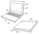
ラップトップ型やノート型のパソコンやワープロ等の携帯用情報機器は、図7(a)に開いた状態の斜視図を、図7(b)に閉じた状態の斜視図を示すように、大別すると2つのユニットから構成されている。すなわち、一方は情報を入力・処理・保存する機能を持つ本体31であり、他方は情報を表示するための表示面32を備えた表示部33である。本体31と表示部33とは、FPC(Flat Package Cable)や電線などで電気的に接続されており、本体からの情報を表示部33に自在に表示させることができる。
【0003】
また、本体31と表示部33とは、本体31に固定された図8に構成図を示したヒンジ部品34を介して開閉自在に接続されている。それにより、本体31に対して必要に応じて自在に表示部33を閉じたり開いたりすることができる。そして、ヒンジ部品34の回転部に適度な摩擦を持たせることにより、表示部33の開き角度を保持することができる。つまり、携帯用情報機器の使用者は、表示部33を見やすく使用しやすい角度に傾斜させて設定することができる。また、携帯用情報機器を使用しないときには、表示部33の表示面32を製品の内側に収納することができるため、破損しやすい表示面32を保護することができる。
【0004】
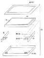
図9は表示部33の分解図である。この図で示すように、表示部33は、省スペースの観点から、一般に液晶表示装置35が用いられている。また、押し込みや落下衝突などの外力から保護するため、液晶表示装置35はPC/ABS樹脂やPC/ABS樹脂にカーボンファイバまたはガラスファイバ、無機フィラー等を添加した樹脂モールドで成形したり、マグネシュウム合金やアルミニウム合金で形成された筐体36の中に収納されている。筐体36は、液晶表示装置35の表示面32以外の面を保護するカバー筐体37と、表示面32の周囲を保護する筐体フレーム38の2つにより構成されている。液晶表示装置35はヒンジ金具39によりカバー筐体37に固定されている。
【0005】
このヒンジ金具39は、本体31と組合わさった状態で表示部33を開くときには、ヒンジ部品34だけにより支持されていると、ヒンジ部品34が表示部33を支持している支持部が短いために支持部に大きな抵抗力が発生する。そのため、ヒンジ部品34が支持しているカバー筐体37の根元に応力が集中し、開閉を繰り返すとカバー筐体37の根元を破損する恐れがある。そのため、構造的にヒンジ金具39を用いることにより、ヒンジ部品34の支持部を支持方向に長くしたものと同様な作用を果たすようにしている。つまり、ヒンジ金具39の領域Aだけでなく、領域Bにおいても表示部33を開くときの荷重を受けることができるようにカバー筐体37を支持するようにしている。このヒンジ金具39は、金属板を切り出して折り曲げることによって形成され、本体31側に設けられたヒンジ部品34とねじ止めされる領域Aと、カバー筐体37や液晶表示装置35と機械的に接続される領域Bとを形成し、領域Aと領域Bとは互いに垂直の位置関係になっている。領域Bは、表示面に対して左右にある、カバー筐体37と液晶表示装置35との間隙に位置しており、複数箇所で、カバー筐体37や液晶表示装置35とねじ止めまたはこれに類する拘束がなされる。また、領域Aのねじ止め部は破損を防止する作用も備えている。
【0006】
図10は、ヒンジ金具39による固定構造の概要説明図である。液晶表示装置35は、側面の対称位置にそれぞれ2個の締結部が形成され、一側面側は、ヒンジに近い締結部はカバー筐体37にヒンジ金具39によりねじ止めにより固定されている。もう一方の締結部はヒンジ金具39を介さずにカバー筐体37に直接ねじ止めされている。他側面側は、液晶表示装置35の側面に形成された突起状の後述する(図11(c)(d)で表示)スペーサ40がカバー筐体37やヒンジ金具39に形成された係合孔に挿入して係合している。
【0007】
図11(a)〜(d)は、締結部の締結方法を示す平面図と側面図とを対にした説明図である。締結方法は大別すると、(イ)カバー筐体37、ヒンジ金具39および液晶表示装置35の3種類の部品が共締めされる場合、(ロ)液晶表示装置35とカバー筐体37とカバー37がねじ止めされる場合、および(ハ)液晶表示装置35がヒンジ金具39やカバー筐体37に対して特定の方向に移動できる場合の3種類が考えられる。
【0008】
図11(a)に(イ)の場合を示す。ヒンジ金具39とカバー筐体37には、ねじ41の山径よりも直径が大きくねじ頭よりは直径の小さい孔が設けられており、ねじ41を液晶表示装置35の側面に形成されているめねじにねじ止めしている。なお、ねじの締結部のカバー筐体37には、ねじの頭がカバー筐体から突設しないようにリブ42による凹部から台座43が形成されている。
【0009】
図5(b)に(ロ)の場合を示す。ヒンジ金具39は液晶表示装置35の左右側面の途中までの長さしかないため、領域Aのねじ止め部が届かない箇所では、液晶表示装置35とカバー筐体37とを直接ねじ止めしている。
【0010】
図5(c)および(d)に(ハ)の場合を示す。液晶表示装置35の寸法公差を吸収するため、(イ)または(ロ)で用いたねじ止めは、表示面32に対して左右どちらかのみで行われている。一方、その反対側では、液晶表示装置35がヒンジ金具39やカバー筐体37に対して移動できるように形成している。すなわち、液晶表示装置35に設けたスペーサ40が、ヒンジ金具39やカバー筐体37に設けた孔(場合によっては長孔)にガイドされることにより、孔とスペーサ40との寸法公差分だけ変位することが可能な構成としている。
【0011】
【発明が解決しようとする課題】
しかしながら、上述の図11(a)〜(d)に示した締結部の締結方法では、(イ)および(ロ)の場合、カバー筐体37の側面には図11(a)および(b)に示すようなねじ41の頭の台座43が必要となる。また、(ハ)の場合のように液晶表示装置35が移動できるような締結方法の場合にも、ヒンジ金具39がないところでは、スペーサ40をガイドするための孔が必要なため、台座43と同じ構造物を設ける必要がある。また、カバー筐体37の内側の左右側の面に台座を設ける場合、台座の強度を確保するため、カバー筐体37の内側から台座43につながるリブ42(図11(a)、(b)および(d)中に図示)が必要となる。
【0012】
図12(a)に衝突前の模式図を示すように、製品が表示面に対して左右方向に落下して、表示部の側面が衝撃力を受けると、図12(b)に衝突後の模式図を示すよう示すように、ねじで固定されているリブ42は衝撃力により変形する。一般に、衝撃荷重を受けてから速度が0になるまでに進む距離、いわゆる制動距離が長いほど、発生する加速度は小さくなる。しかし、リブ42は落下方向に立設しているため、液晶表示装置35の変位を拘束する作用をもつ。そのため、液晶表示装置35に大きな加速度が生じて破損する場合が発生する。
【0013】
本発明はこれの事情に基づいてなされたもので、表示部を繰り返し開閉してもヒンジを固定している表示部の筐体が破損せず、また、落下強度を向上させることができる液晶表示装置の取付け構造と、それを用いた携帯用情報機器を提供することを目的としている。
【0014】
【課題を解決するための手段】
請求項1の発明による手段によれば、本体部にヒンジ金具により開閉自在に取り付けられた液晶表示装置を有する携帯用情報機器において、
前記ヒンジ金具は、弾性変形可能な屈曲部を有していることを特徴とする携帯用情報機器である。
【0015】
また請求項2の発明による手段によれば、前記屈曲部は略台形形状をなしていることを特徴とする携帯用情報機器である。
【0016】
また請求項3の発明による手段によれば、前記液晶表示装置は筐体に収納されており、前記筐体の前記屈曲部と対向する位置には舌片が設けられ、この舌片は前記ヒンジ金具の側面を係止していることを特徴とする携帯用情報機器である。
【0017】
【発明の実施の形態】
以下、本発明の実施の形態を図面を参照して説明する。
【0018】
ラップトップ型やノート型のパソコンやワープロ等の携帯用情報機器の基本構造は、従来の技術の項で図7(a)、図7(b)図8および図9を参照して説明したので省略する。
【0019】
今般、発明者は、従来のようにヒンジ金具を、単に液晶表示装置をカバー筐体に取付ける手段として用いるだけでなく、ヒンジ金具の形状や液晶表示装置の固定方法について種々検討した結果、以下に説明するように、外部からの振動や衝撃に耐えうる機能を付加与することが可能であることを確認した。
【0020】
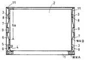
すなわち、図1は、カバー筐体1への液晶表示装置2の取付け状態を示す平面図である。カバー筐体1の内部に収納される液晶表示装置2の側面には、一方の側(図1において右側)に離間して2個の突起状のスペーサ3が形成され、他方の側(図1において左側)の対称位置には、液晶表示装置2が開閉する際の開放端側に突起状のスペーサ3が、また、根元側にはめねじ4が設けられている。カバー筐体1におねじ5によりねじ止めされて固定され、弾性体の金属(SUS等)で形成されたヒンジ金具6の延在部6aは、カバー筐体1と液晶表示装置2の側面との間に台形状(ただし、底辺が無いので富士山状ともいえる)に屈曲して屈曲部7を形成してカバー筐体1と液晶表示装置2との間に介在している。この屈曲部7により、液晶表示装置2の両側面を弾性的に保持している。また、ヒンジ金具6の液晶表示装置2に設けられたスペーサ3或いはめねじ4に対応する箇所には、それぞれガイド孔8が孔設されており、スペーサ3がそれぞれにガイドされて挿着され、また、めねじ4に対応する箇所はおねじ5により液晶表示装置2がヒンジ金具6に螺着されている。
【0021】
ヒンジ金具6の屈曲部7の形状は、基本的には液晶表示装置2の側面がカバー筐体1の対向面に対して平行になるように左右の両方向から均等な弾性力を付与できる形状であればよく、上述のように側面形状が底辺のない台形状(富士山状)を対象方向に凸設させて設ければよい。その場合、頂部がカバー筐体1に密接するようにしている。なお、稜線は直線状でなくても弧を描いた曲線状でも良いが、頂部はカバー筐体1との接触が面接触(線接触)になるように平坦な直線状に形成する。また、その数は1個ではなく複数個を設けてもよい。
【0022】
カバー筐体1のヒンジ金具6との接触部には、ヒンジ金具6の側面を係止する突起状のリブの舌片9が形成されており、この舌片9によっても液晶表示装置2のカバー筐体1からの離脱を防止している。また、開放端側に設けられているリブ11は液晶表示装置2が外力により移動した際のストッパとしての機能を果たしている。
【0023】
これらの構造により、液晶表示装置2をカバー筐体1に装着した状態で、液晶表示装置2の表示部が表示面に対して左右方向に落下した場合に、ヒンジ金具6の屈曲部7が変形することによって、液晶表示装置2に生じる加速度を低減させることができる。
【0024】
図2に斜視図を示すように、実際に上述の構造と従来の構造との液晶表示装置2をカバー筐体1に装着した状態で、高さ100mmから落下させて、液晶表示装置2の表示面に対して右側面が衝突した場合の落下衝撃解析を行い、液晶表示装置2に生じる落下方向の加速度を求めた。なお、ch1〜ch5は加速度Gの測定位置である。
【0025】
図3(a)は従来の構造の加速度の履歴であり、図3(b)は上述の構造の加速度の履歴を示すグラフである。いずれの場合も、ch1〜ch5では、ほぼ同様な傾向を示しており、上述の構造の場合(図3(b))の方が加速度が小さくなっていることが分かる。なお、横軸は時間、縦軸は加速度である。
【0026】
これらの比較結果から、図3(a)で示した従来の構造から、図3(b)で示した上述の実施の形態で示した構造に変更することで、加速度の最大値をほぼ半減させることができ、液晶表示装置2の受ける衝撃を大幅に緩和することができることが確認できた。
【0027】
また、上述の図1で示した構造によれば、ヒンジ金具6を液晶表示装置2の左右に1つずつ設け、左右のうち、一方のみで液晶表示装置2とねじ止めし、その他のヒンジ金具6のガイド孔8は液晶表示装置2に設けたスペーサ3がガイド孔8にガイドされて挿入さる構造となっているため、この組合わせにより表示部を製造する際に、部品の組み立て公差を吸収できる。
【0028】
また、カバー筐体1の左右内側の側面には、張り出した舌片9を設けてカバー筐体1の一部として成形していた。この舌片9により、ヒンジ金具6の領域Bのうち、台形上部で台形上辺部でカバー筐体1の側面に近接した部分を覆うように設けられ、これにより、表示部を開く際に、カバー筐体1からヒンジ金具6や液晶表示装置2が乖離することを防止できる。
【0029】
また、ヒンジ金具6のねじ止めされない側の先端は、カバー筐体1に設けたリブにより、ヒンジ金具6の長手方向の変位が拘束される。これにより、表示部が表示面に対して上下方向に落下した場合に、ねじ止め箇所とリブによる拘束箇所の両方で衝撃力をうけることができるので、ねじ止め箇所の受ける衝撃力を緩和することができて、ねじ止め箇所の破損を防止できる。
【0030】
次に、上述の実施の形態の変形例について説明する。
(変形例1)
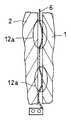
図4にヒンジ金具6の模式図を示すように、上述の実施の形態ではヒンジ金具6の延在部6aの中央に、屈曲部7として底辺のない台形を1箇所設けた例を示したが、台形を複数個設けてた場合、すなわち、屈曲部12a、12aを2つ設けた場合について説明する。ヒンジ金具6のばね特性は台形部分の数に応じてそれぞれで分散して発生する。つまり、台形部分が多いほど、ばねをより多く並列に配置することになるため、落下に対するヒンジ金具6の剛性は高くなる。落下高さが高い場合や液晶表示装置2の質量が大きい場合には、高い剛性が求められるが、一方、落下高さが低い場合や液晶表示装置2の質量が小さい場合、剛性が必要以上に高いと、適切なばね特性を持つことができないため、低い剛性が求められる。つまりヒンジ金具6に一様な台形形状を形成した場合は、必要とされる剛性に応じて、屈曲部12aの個数を選定すればよい。
(変形例2)
図5にヒンジ金具6の模式図を示す。実際に落下する際には、落下高さが低い場合(すなわち、低い剛性のヒンジ金具6が求められる場合)と、落下高さが高い場合(すなわち、高い剛性のヒンジ金具6が求められる場合)の両方が起こりうる。
【0031】
そこで、図5に示すように、ヒンジ金具6に異なる大きさの屈曲部12b、12cを形成し、落下高さが低い場合には、屈曲部12bがばねとして作用する。落下高さが高い場合には、屈曲部12bに加えて屈曲部12cもばねとして作用する。このため、落下高さに応じてヒンジ金具6の剛性を変化させることができる。いうまでもなく、1つのヒンジ金具6が持つ屈曲部12b、12cの種類は2種類に限定されないし、屈曲部12b、12cの個数も2つに限定されない。また、ヒンジ金具6の屈曲部12b、12cの部分の斜辺は、その傾斜が高いほど、ばねとしての剛性は高くなる。例えば、そこで、屈曲部12cよりも屈曲部12bの傾斜を高くする。これにより、屈曲部12bのばねとしての剛性をより高くすることができる。
(変形例3)
図6にヒンジ金具6による保持部の模式図を示す。(変形例1)及び(変形例2)では、台形形状の屈曲部を直線上に配列した例を示したが、図6に示すように、複数の屈曲部12d〜12gを連なるように形成してヒンジ金具6全体が湾曲した構造にすることもできる。この場合、屈曲部12eと屈曲部12fの頂部がカバー筐体1と接する構造になる。これにより、落下高さが増加するにつれて、ばねとして作用する屈曲部部分も増加するため、落下高さが低い場合と落下高さが高い場合の両方に対応することが可能になる。
【0032】
以上に説明したように、上述の各実施の形態によれば、液晶表示装置2の側面を弾性的に支持してカバー筐体1に固定しているので、表示部を繰り返し開閉してもヒンジを固定しているカバー筐体1が破損せず、また、落下強度を向上させることができる。
【0033】
それにより、ラップトップ型やノート型のパソコンやワープロ等の携帯用情報機器が、外部からの振動や衝撃を受けても大きな損傷を受けることを防止できる。
【0034】
【発明の効果】
本発明によれば、カバー筐体に保持された液晶表示装置の落下強度を向上させることができる。
【0035】
また、外部からの振動や衝撃に強い携帯用情報機器が実現できる。
【図面の簡単な説明】
【図1】本発明のカバー筐体への液晶表示装置の取付け状態を示す平面図。
【図2】液晶表示装置をカバー筐体に装着した斜視図。
【図3】(a)は落下衝撃解析での、従来の構造の加速度の履歴のグラフ。(b)は同本発明の構造の加速度の履歴のグラフ。
【図4】本発明によるヒンジ金具による保持部の変形例の模式図。
【図5】本発明によるヒンジ金具による保持部の変形例の模式図。
【図6】本発明によるヒンジ金具による保持部の変形例の模式図。
【図7】(a)携帯用情報機器の表示部を開いた状態の斜視図、(b)同閉じた状態の斜視図。
【図8】ヒンジ部品の構成図。
【図9】従来の表示部の分解図。
【図10】従来のヒンジ金具による固定構造の概要説明図。
【図11】(a)〜(d)、従来の締結部の締結方法を示す説明図。
【図12】(a)は衝突前の模式図、(b)は衝突後の模式図。
【符号の説明】
1…カバー筐体、2…液晶表示装置、3…スペーサ、6…ヒンジ金具、7…屈曲部、9…舌片、12a〜12g…屈曲部、31…本体、32…表示面、33…表示部[0001]
BACKGROUND OF THE INVENTION
The present invention relates to a portable information device having a liquid crystal display device.
[0002]
[Prior art]
A portable information device such as a laptop or notebook personal computer or word processor has a large perspective view as shown in FIG. 7 (a) and a closed perspective view in FIG. 7 (b). In other words, it is composed of two units. That is, one is a
[0003]
Further, the
[0004]
FIG. 9 is an exploded view of the
[0005]
When the
[0006]
FIG. 10 is a schematic explanatory diagram of a fixing structure using the
[0007]
11A to 11D are explanatory views in which a plan view and a side view showing a fastening method of the fastening portion are paired. The fastening methods are roughly classified as follows: (a) When three types of parts, that is, the
[0008]
FIG. 11A shows the case of (A). The
[0009]
FIG. 5B shows the case of (B). Since the
[0010]
FIGS. 5C and 5D show the case of (C). In order to absorb the dimensional tolerance of the liquid
[0011]
[Problems to be solved by the invention]
However, in the fastening method of the fastening part shown in FIGS. 11A to 11D described above, in the case of (A) and (B), the side surface of the
[0012]
As shown in the schematic diagram before the collision in FIG. 12 (a), when the product falls in the left-right direction with respect to the display surface and the side surface of the display unit receives an impact force, FIG. As shown in the schematic diagram, the
[0013]
The present invention has been made on the basis of these circumstances, and a liquid crystal display capable of improving the drop strength without damaging the casing of the display unit fixing the hinge even when the display unit is repeatedly opened and closed. An object is to provide a device mounting structure and a portable information device using the device mounting structure.
[0014]
[Means for Solving the Problems]
According to the means of the first aspect of the present invention, in the portable information device having a liquid crystal display device attached to the main body portion by a hinge bracket so as to be freely opened and closed,
The hinge fitting is a portable information device characterized by having a bent portion that can be elastically deformed.
[0015]
According to a second aspect of the present invention, there is provided a portable information device characterized in that the bent portion has a substantially trapezoidal shape.
[0016]
According to the invention of
[0017]
DETAILED DESCRIPTION OF THE INVENTION
Hereinafter, embodiments of the present invention will be described with reference to the drawings.
[0018]
The basic structure of a portable information device such as a laptop or notebook personal computer or word processor has been described in the prior art section with reference to FIGS. 7 (a), 7 (b), 8 and 9. Omitted.
[0019]
Recently, the inventor has not only used the hinge fitting as a means for attaching the liquid crystal display device to the cover housing as in the prior art, but also conducted various studies on the shape of the hinge fitting and the fixing method of the liquid crystal display device. As explained, it was confirmed that a function capable of withstanding external vibrations and shocks can be added.
[0020]
That is, FIG. 1 is a plan view showing a state in which the liquid
[0021]
The shape of the
[0022]
At the contact portion of the
[0023]
With these structures, when the display unit of the liquid
[0024]
As shown in a perspective view in FIG. 2, the liquid
[0025]
FIG. 3A is an acceleration history of the conventional structure, and FIG. 3B is a graph showing an acceleration history of the above-described structure. In any case, ch1 to ch5 show almost the same tendency, and it can be seen that the acceleration is smaller in the case of the above-described structure (FIG. 3B). The horizontal axis is time, and the vertical axis is acceleration.
[0026]
From these comparison results, the maximum value of acceleration is almost halved by changing from the conventional structure shown in FIG. 3A to the structure shown in the above-described embodiment shown in FIG. 3B. It was confirmed that the impact received by the liquid
[0027]
Further, according to the structure shown in FIG. 1 described above, one hinge fitting 6 is provided on each of the left and right sides of the liquid
[0028]
In addition, protruding
[0029]
Further, the displacement of the hinge fitting 6 in the longitudinal direction is restricted by the rib provided on the
[0030]
Next, a modification of the above embodiment will be described.
(Modification 1)
As shown in the schematic diagram of the hinge fitting 6 in FIG. 4, in the above-described embodiment, an example in which a trapezoid having no bottom as the
(Modification 2)
FIG. 5 shows a schematic diagram of the
[0031]
Therefore, as shown in FIG. 5, when the
(Modification 3)
FIG. 6 shows a schematic view of a holding portion by the
[0032]
As described above, according to each of the above-described embodiments, the side surface of the liquid
[0033]
Accordingly, it is possible to prevent a portable information device such as a laptop computer, a notebook computer, or a word processor from being greatly damaged even when subjected to external vibration or impact.
[0034]
【The invention's effect】
ADVANTAGE OF THE INVENTION According to this invention, the drop strength of the liquid crystal display device hold | maintained at the cover housing | casing can be improved.
[0035]
In addition, a portable information device that is resistant to external vibration and impact can be realized.
[Brief description of the drawings]
FIG. 1 is a plan view showing an attachment state of a liquid crystal display device to a cover housing of the present invention.
FIG. 2 is a perspective view of a liquid crystal display device mounted on a cover housing.
FIG. 3A is a graph of the acceleration history of a conventional structure in a drop impact analysis. (B) is a graph of the acceleration history of the structure of the present invention.
FIG. 4 is a schematic view of a modified example of the holding portion by the hinge metal fitting according to the present invention.
FIG. 5 is a schematic view of a modified example of the holding portion by the hinge fitting according to the present invention.
FIG. 6 is a schematic view of a modified example of the holding portion by the hinge metal fitting according to the present invention.
7A is a perspective view of a portable information device in a state where a display unit is opened, and FIG. 7B is a perspective view of the portable information device in a closed state.
FIG. 8 is a configuration diagram of a hinge part.
FIG. 9 is an exploded view of a conventional display unit.
FIG. 10 is a schematic explanatory diagram of a fixing structure using a conventional hinge fitting.
11A to 11D are explanatory views showing a conventional fastening method of a fastening portion.
12A is a schematic diagram before a collision, and FIG. 12B is a schematic diagram after the collision.
[Explanation of symbols]
DESCRIPTION OF
Claims (3)
Translated fromJapanese前記ヒンジ金具は、ヒンジ部品とねじ止めされる領域を除く部分に屈曲部を有し、前記屈曲部は液晶表示装置の側面がカバー筐体の対向面に対して平行となる形状へ弾性変形可能であり、
前記屈曲部と前記液晶表示装置とは固定されていないことを特徴とする携帯用情報機器。In a portable information device having a liquid crystal display device attached to a main body portion by a hinge bracket so as to be freely opened and closed,
The hinge fitting has abent portion in a portion excluding ahinge part and a region to be screwed, and the bent portion can be elastically deformed into a shape in which the side surface of the liquid crystal display device is parallel to the facing surface of the cover housing. And
The portable information apparatus,wherein the bent portion and the liquid crystal display device are not fixed .
前記ヒンジ金具は、ヒンジ部品とねじ止めされる領域を除く部分に形成された底辺のない台形状をなす屈曲部を有し、前記屈曲部と液晶表示装置とは固定されておらず前記台形形状が弾性変形することで前記液晶表示装置の側面がカバー筐体の対向面に対して平行となる形状を維持することを特徴とする携帯用情報機器。 The hinge fitting has a bent portion having a trapezoidal shape without a bottom formed in a portion excluding a hinge part and a region to be screwed, and the bent portion and the liquid crystal display device are not fixed and the trapezoidal shape The portable information device is characterized by maintaining a shape in which the side surface of the liquid crystal display device is parallel to the facing surface of the cover casing by elastically deforming the liquid crystal display.
Priority Applications (2)
| Application Number | Priority Date | Filing Date | Title |
|---|---|---|---|
| JP2002011312AJP3673223B2 (en) | 2002-01-21 | 2002-01-21 | Portable information equipment |
| US10/347,494US6859357B2 (en) | 2002-01-21 | 2003-01-21 | Portable information apparatus |
Applications Claiming Priority (1)
| Application Number | Priority Date | Filing Date | Title |
|---|---|---|---|
| JP2002011312AJP3673223B2 (en) | 2002-01-21 | 2002-01-21 | Portable information equipment |
Publications (2)
| Publication Number | Publication Date |
|---|---|
| JP2003216273A JP2003216273A (en) | 2003-07-31 |
| JP3673223B2true JP3673223B2 (en) | 2005-07-20 |
Family
ID=27648818
Family Applications (1)
| Application Number | Title | Priority Date | Filing Date |
|---|---|---|---|
| JP2002011312AExpired - Fee RelatedJP3673223B2 (en) | 2002-01-21 | 2002-01-21 | Portable information equipment |
Country Status (2)
| Country | Link |
|---|---|
| US (1) | US6859357B2 (en) |
| JP (1) | JP3673223B2 (en) |
Families Citing this family (77)
| Publication number | Priority date | Publication date | Assignee | Title |
|---|---|---|---|---|
| KR100928482B1 (en)* | 2002-12-24 | 2009-11-26 | 엘지디스플레이 주식회사 | LCD Display |
| JP3696210B2 (en)* | 2003-01-31 | 2005-09-14 | 株式会社東芝 | Electronics |
| USD525975S1 (en)* | 2003-07-11 | 2006-08-01 | Hewlett-Packard Development Company, L.P. | Optical scanner |
| JP4080990B2 (en) | 2003-11-28 | 2008-04-23 | 株式会社東芝 | Portable electronic device |
| JP2005260499A (en)* | 2004-03-10 | 2005-09-22 | Toshiba Corp | Display device |
| KR20050109310A (en)* | 2004-05-13 | 2005-11-21 | 삼성전자주식회사 | Display apparatus |
| EP1621962A1 (en)* | 2004-07-23 | 2006-02-01 | VAC Corporation | Notebook having a display apparatus with changeable shells |
| KR100592291B1 (en)* | 2004-08-28 | 2006-06-22 | 삼성에스디아이 주식회사 | Display device |
| KR100669753B1 (en)* | 2004-11-10 | 2007-01-16 | 삼성에스디아이 주식회사 | Member for Plasma Display Panel Support and Plasma Display Device Equipped with the Same |
| TWM276250U (en)* | 2005-05-12 | 2005-09-21 | Twinhead Int Corp | Structure for the display module of a portable computer |
| JP4746931B2 (en)* | 2005-07-22 | 2011-08-10 | 株式会社日立製作所 | Flat display panel module and flat display device |
| JP2007058583A (en)* | 2005-08-24 | 2007-03-08 | Fujitsu Ltd | Electronic equipment and assembly parts |
| CN2849766Y (en)* | 2005-10-24 | 2006-12-20 | 鸿富锦精密工业(深圳)有限公司 | Liquid crystal display |
| US8020902B1 (en) | 2006-01-13 | 2011-09-20 | Flextronics Ap, Llc | Integrated snap and handling feature |
| JP4786366B2 (en)* | 2006-02-20 | 2011-10-05 | 日立プラズマディスプレイ株式会社 | Plasma display device |
| CN2909316Y (en)* | 2006-04-28 | 2007-06-06 | 鸿富锦精密工业(深圳)有限公司 | LCD Monitor |
| JP2007328613A (en)* | 2006-06-08 | 2007-12-20 | Toshiba Corp | Electronics |
| CN101677682B (en)* | 2007-03-29 | 2012-08-22 | 弗莱克斯电子有限责任公司 | Combination devices clamp spring designed with devices cage |
| JP4786611B2 (en) | 2007-08-09 | 2011-10-05 | 富士通株式会社 | Electronics |
| JP5040532B2 (en)* | 2007-08-31 | 2012-10-03 | 富士通株式会社 | Electronics |
| CN201035465Y (en)* | 2007-09-12 | 2008-03-12 | 联想(北京)有限公司 | Notebook computer screen and notebook computer |
| JP5104298B2 (en) | 2007-12-27 | 2012-12-19 | 富士通株式会社 | Analysis model creation apparatus and method, and program |
| TWI357762B (en)* | 2008-02-14 | 2012-02-01 | Pegatron Corp | Display apparatus and bracket thereof |
| CN101518404A (en)* | 2008-02-29 | 2009-09-02 | 鹏智科技(深圳)有限公司 | Digital photo frame and outer frame thereof |
| TW201022765A (en)* | 2008-12-04 | 2010-06-16 | Hannspree Inc | Panel holding device and method |
| US8248777B2 (en) | 2008-05-23 | 2012-08-21 | Apple Inc. | Viscoelastic material for shock protection in an electronic device |
| US8309245B2 (en)* | 2009-06-06 | 2012-11-13 | Apple Inc. | Battery pack and connector |
| US8199469B2 (en)* | 2009-06-06 | 2012-06-12 | Apple Inc. | Battery |
| US8199477B2 (en)* | 2009-06-11 | 2012-06-12 | Apple Inc. | Portable computers with spring-mounted displays |
| TWM370766U (en)* | 2009-08-25 | 2009-12-11 | Quanta Comp Inc | Electronic device |
| US8892238B2 (en)* | 2009-10-06 | 2014-11-18 | Edward T. Sweet | Edge break details and processing |
| US20110081839A1 (en)* | 2009-10-06 | 2011-04-07 | Apple Inc. | Method and apparatus for polishing a curved edge |
| US8111505B2 (en)* | 2009-10-16 | 2012-02-07 | Apple Inc. | Computer housing |
| US8233109B2 (en) | 2009-10-16 | 2012-07-31 | Apple Inc. | Portable computer display housing |
| US8199468B2 (en)* | 2009-10-16 | 2012-06-12 | Apple Inc. | Computer housing |
| US8333862B2 (en)* | 2009-10-16 | 2012-12-18 | Apple Inc. | Self fixturing assembly techniques |
| US20110089792A1 (en)* | 2009-10-16 | 2011-04-21 | Apple Inc. | Portable computer housing |
| WO2011047094A2 (en) | 2009-10-16 | 2011-04-21 | Apple Inc. | Portable computing system |
| US8553907B2 (en)* | 2009-10-16 | 2013-10-08 | Apple Inc. | Portable computer electrical grounding and audio system architectures |
| US8854801B2 (en)* | 2009-10-16 | 2014-10-07 | Apple Inc. | Portable computer display housing |
| AU2012216762B2 (en)* | 2009-10-16 | 2014-02-20 | Apple Inc. | Computer housing |
| US9268360B2 (en)* | 2009-11-30 | 2016-02-23 | Flextronics Ap, Llc | Apparatus for and method of screwless assembly and adjustable damping structure for panel stress relief |
| US8305744B2 (en) | 2010-05-14 | 2012-11-06 | Apple Inc. | Shock mounting cover glass in consumer electronics devices |
| TWI393522B (en)* | 2010-08-19 | 2013-04-11 | Au Optronics Corp | Panel module with simplified supporting structure and portable electronic apparatus therewith |
| US8638549B2 (en) | 2010-08-24 | 2014-01-28 | Apple Inc. | Electronic device display module |
| JP2012048128A (en)* | 2010-08-30 | 2012-03-08 | Panasonic Corp | Electronic apparatus |
| CN102608772A (en)* | 2011-01-24 | 2012-07-25 | 深圳富泰宏精密工业有限公司 | Window installation fixture |
| TW201232099A (en)* | 2011-01-25 | 2012-08-01 | Wintek Corp | Display having a frame, touch display, and method of manufacturing a frame |
| US9176535B2 (en) | 2011-06-03 | 2015-11-03 | Microsoft Technology Licensing, Llc | Flexible display flexure assembly |
| US8804324B2 (en) | 2011-06-03 | 2014-08-12 | Microsoft Corporation | Flexible display overcenter assembly |
| TWM423425U (en)* | 2011-09-16 | 2012-02-21 | Wistron Corp | Frame assembly and panel device therewith |
| US9342108B2 (en) | 2011-09-16 | 2016-05-17 | Apple Inc. | Protecting an electronic device |
| US9129659B2 (en)* | 2011-10-25 | 2015-09-08 | Apple Inc. | Buckling shock mounting |
| TWM434227U (en)* | 2011-11-15 | 2012-07-21 | Pegatron Corp | Thin display |
| US9201452B2 (en) | 2012-02-28 | 2015-12-01 | Apple Inc. | Electronic device with illuminated logo structures |
| US8862182B2 (en) | 2012-08-31 | 2014-10-14 | Apple Inc. | Coupling reduction for electromechanical actuator |
| US8897007B2 (en) | 2012-10-18 | 2014-11-25 | Apple Inc. | Grounding features of a portable computing device |
| TW201426253A (en)* | 2012-12-27 | 2014-07-01 | Acer Inc | Electronic device |
| CN103941808A (en)* | 2013-01-22 | 2014-07-23 | 宏碁股份有限公司 | Electronic device |
| US9482898B2 (en)* | 2013-02-26 | 2016-11-01 | Kyocera Corporation | Liquid crystal display apparatus |
| US9432492B2 (en) | 2013-03-11 | 2016-08-30 | Apple Inc. | Drop countermeasures for electronic device |
| US9505032B2 (en) | 2013-03-14 | 2016-11-29 | Apple Inc. | Dynamic mass reconfiguration |
| US9715257B2 (en) | 2014-04-18 | 2017-07-25 | Apple Inc. | Active screen protection for electronic device |
| US9612622B2 (en) | 2014-05-13 | 2017-04-04 | Apple Inc. | Electronic device housing |
| US9571150B2 (en) | 2014-05-21 | 2017-02-14 | Apple Inc. | Screen protection using actuated bumpers |
| US10310602B2 (en) | 2014-07-11 | 2019-06-04 | Apple Inc. | Controlled gyroscopic torque for an electronic device |
| US9558781B1 (en) | 2014-10-16 | 2017-01-31 | Flextronics Ap, Llc | Method for selecting individual discs from tightly spaced array of optical discs |
| EP3048475B1 (en)* | 2015-01-22 | 2018-10-24 | Canon Kabushiki Kaisha | Display device |
| USD768619S1 (en)* | 2015-03-06 | 2016-10-11 | Apple Inc. | Display |
| CN105523281B (en)* | 2016-01-04 | 2020-08-07 | 京东方科技集团股份有限公司 | Elastic supporting structure and display device comprising same |
| JP6125073B1 (en)* | 2016-04-26 | 2017-05-10 | レノボ・シンガポール・プライベート・リミテッド | Housing member and electronic device |
| WO2018094890A1 (en)* | 2016-11-28 | 2018-05-31 | 华为技术有限公司 | Notebook computer |
| JP6643723B2 (en)* | 2017-01-05 | 2020-02-12 | 富士通クライアントコンピューティング株式会社 | Information processing terminal and hinge unit |
| CN207783372U (en)* | 2018-01-26 | 2018-08-28 | 佳能企业股份有限公司 | Electronic device and stop structure thereof |
| US10838452B2 (en)* | 2018-02-07 | 2020-11-17 | Microsoft Technology Licensing, Llc | Computing device display bonding |
| KR20210126175A (en)* | 2020-04-09 | 2021-10-20 | 삼성디스플레이 주식회사 | Display device |
| CN111754871B (en)* | 2020-06-23 | 2022-05-27 | 武汉华星光电半导体显示技术有限公司 | Display screen and display device |
Family Cites Families (6)
| Publication number | Priority date | Publication date | Assignee | Title |
|---|---|---|---|---|
| JP3725633B2 (en)* | 1996-10-21 | 2005-12-14 | 株式会社東芝 | Portable equipment |
| DE69832752T2 (en)* | 1997-05-06 | 2006-09-07 | Samsung Electronics Co., Ltd., Suwon | Swivel device and portable computer with swivel device |
| KR100256971B1 (en)* | 1997-05-24 | 2000-05-15 | 구본준 | Lcd module fixing device for notebook computers |
| JPH116998A (en)* | 1997-06-09 | 1999-01-12 | Internatl Business Mach Corp <Ibm> | Liquid crystal panel and liquid crystal display device |
| US6501641B1 (en)* | 1998-10-23 | 2002-12-31 | Lg. Philips Lcd Co. Ltd. | Portable computer having a flat panel display device |
| KR100508003B1 (en)* | 1998-11-11 | 2005-11-21 | 엘지.필립스 엘시디 주식회사 | How to combine a portable computer with its flat panel display |
- 2002
- 2002-01-21JPJP2002011312Apatent/JP3673223B2/ennot_activeExpired - Fee Related
- 2003
- 2003-01-21USUS10/347,494patent/US6859357B2/ennot_activeExpired - Lifetime
Also Published As
| Publication number | Publication date |
|---|---|
| JP2003216273A (en) | 2003-07-31 |
| US6859357B2 (en) | 2005-02-22 |
| US20030197111A1 (en) | 2003-10-23 |
Similar Documents
| Publication | Publication Date | Title |
|---|---|---|
| JP3673223B2 (en) | Portable information equipment | |
| JP4080990B2 (en) | Portable electronic device | |
| JP4714296B1 (en) | Electronics | |
| CN101395036B (en) | Mechanism for opening and closing monitor | |
| KR100644306B1 (en) | Electronic apparatus | |
| US9693470B2 (en) | Electric device with surrounding protective frame | |
| US20100046166A1 (en) | Information processing unit | |
| JP2009098427A (en) | Electronic device and frame member | |
| JP2008152121A (en) | Adapter holder and display device | |
| JP5810807B2 (en) | Electronics | |
| JP2013077257A (en) | Hinge unit, and electronic equipment provided with hinge unit | |
| JP2010280396A (en) | Shock absorber, storage medium holding device, and storage medium storage system | |
| JP4573740B2 (en) | Attachment for protection of electronic equipment | |
| JP2006277496A (en) | Electronics | |
| JP6024978B2 (en) | Electronic equipment and electronic parts storage case | |
| JP2012183925A (en) | Vehicle mounted camera | |
| JP5896079B2 (en) | Electronic device, built-in device, and elastic member | |
| JP2007179151A (en) | Electronics | |
| JP2024082701A (en) | Electronic equipment protection and electronic equipment unit | |
| JP7345967B2 (en) | electrical equipment storage box | |
| JP6673662B2 (en) | card case | |
| JP7697336B2 (en) | electronic equipment | |
| JP5204510B2 (en) | Card slot device and electronic device | |
| JP4908659B2 (en) | Electronics | |
| JP7696679B2 (en) | Storage boxes for electrical equipment and cabinets for storing electrical equipment |
Legal Events
| Date | Code | Title | Description |
|---|---|---|---|
| A977 | Report on retrieval | Free format text:JAPANESE INTERMEDIATE CODE: A971007 Effective date:20040531 | |
| A131 | Notification of reasons for refusal | Free format text:JAPANESE INTERMEDIATE CODE: A131 Effective date:20040608 | |
| A521 | Written amendment | Free format text:JAPANESE INTERMEDIATE CODE: A523 Effective date:20040805 | |
| RD04 | Notification of resignation of power of attorney | Free format text:JAPANESE INTERMEDIATE CODE: A7424 Effective date:20040809 | |
| TRDD | Decision of grant or rejection written | ||
| A01 | Written decision to grant a patent or to grant a registration (utility model) | Free format text:JAPANESE INTERMEDIATE CODE: A01 Effective date:20050412 | |
| A61 | First payment of annual fees (during grant procedure) | Free format text:JAPANESE INTERMEDIATE CODE: A61 Effective date:20050421 | |
| FPAY | Renewal fee payment (event date is renewal date of database) | Free format text:PAYMENT UNTIL: 20080428 Year of fee payment:3 | |
| FPAY | Renewal fee payment (event date is renewal date of database) | Free format text:PAYMENT UNTIL: 20090428 Year of fee payment:4 | |
| LAPS | Cancellation because of no payment of annual fees |