JP3672966B2 - Method and apparatus for creating dental prediction model - Google Patents
Method and apparatus for creating dental prediction modelDownload PDFInfo
- Publication number
- JP3672966B2 JP3672966B2JP11379095AJP11379095AJP3672966B2JP 3672966 B2JP3672966 B2JP 3672966B2JP 11379095 AJP11379095 AJP 11379095AJP 11379095 AJP11379095 AJP 11379095AJP 3672966 B2JP3672966 B2JP 3672966B2
- Authority
- JP
- Japan
- Prior art keywords
- tooth
- line
- plane
- representative
- point
- Prior art date
- Legal status (The legal status is an assumption and is not a legal conclusion. Google has not performed a legal analysis and makes no representation as to the accuracy of the status listed.)
- Expired - Fee Related
Links
Images


Classifications
- A—HUMAN NECESSITIES
- A61—MEDICAL OR VETERINARY SCIENCE; HYGIENE
- A61C—DENTISTRY; APPARATUS OR METHODS FOR ORAL OR DENTAL HYGIENE
- A61C7/00—Orthodontics, i.e. obtaining or maintaining the desired position of teeth, e.g. by straightening, evening, regulating, separating, or by correcting malocclusions
- A61C7/002—Orthodontic computer assisted systems
- A61C2007/004—Automatic construction of a set of axes for a tooth or a plurality of teeth
- A—HUMAN NECESSITIES
- A61—MEDICAL OR VETERINARY SCIENCE; HYGIENE
- A61C—DENTISTRY; APPARATUS OR METHODS FOR ORAL OR DENTAL HYGIENE
- A61C9/00—Impression cups, i.e. impression trays; Impression methods
- A61C9/004—Means or methods for taking digitized impressions
- A61C9/0046—Data acquisition means or methods
- A61C9/0053—Optical means or methods, e.g. scanning the teeth by a laser or light beam
- G—PHYSICS
- G16—INFORMATION AND COMMUNICATION TECHNOLOGY [ICT] SPECIALLY ADAPTED FOR SPECIFIC APPLICATION FIELDS
- G16H—HEALTHCARE INFORMATICS, i.e. INFORMATION AND COMMUNICATION TECHNOLOGY [ICT] SPECIALLY ADAPTED FOR THE HANDLING OR PROCESSING OF MEDICAL OR HEALTHCARE DATA
- G16H20/00—ICT specially adapted for therapies or health-improving plans, e.g. for handling prescriptions, for steering therapy or for monitoring patient compliance
- G16H20/40—ICT specially adapted for therapies or health-improving plans, e.g. for handling prescriptions, for steering therapy or for monitoring patient compliance relating to mechanical, radiation or invasive therapies, e.g. surgery, laser therapy, dialysis or acupuncture
Landscapes
- Health & Medical Sciences (AREA)
- Engineering & Computer Science (AREA)
- General Engineering & Computer Science (AREA)
- Oral & Maxillofacial Surgery (AREA)
- Dentistry (AREA)
- Epidemiology (AREA)
- Life Sciences & Earth Sciences (AREA)
- Animal Behavior & Ethology (AREA)
- General Health & Medical Sciences (AREA)
- Public Health (AREA)
- Veterinary Medicine (AREA)
- Dental Tools And Instruments Or Auxiliary Dental Instruments (AREA)
Description
Translated fromJapanese【0001】
【産業上の利用分野】
この発明は、歯科治療に用いられる歯科用予測模型の作成方法および装置に関し、その容易化に関するものである。
【0002】
【従来の技術】
一般に、歯科矯正や義歯作成などの歯科治療において、患者の歯と顎堤の印象を採った印象模型に基づいて、予測模型を作成する場合が多い。この予測模型は、印象模型の顎堤上の個々の歯を1本ずつ切り出して、再排列を行って作成される。この作成された予測模型により、歯科治療の最終的な目標が明確になり、また、具体的に上下顎の咬合状態などを確認できる。
【0003】
また、患者は、この予測模型が示されることにより、歯科治療の最終状態を視覚的に認識することができるので、患者の心理面からも好ましい。
【0004】
【発明が解決しようとする課題】
しかしながら、従来の予測模型の作成は手作業で行われるため、煩雑で時間がかかっていた。また、歯科治療の目標を達成するための手段が複数考えられる場合には、この作業はきわめて煩雑になり、作業の時間短縮,省力化が強く望まれる課題となっていた。
【0005】
この発明は上記の問題点を解決して、容易に予測模型を作成することができる歯科用予測模型の作成方法および作成装置を提供することを目的としている。
【0006】
【課題を解決するための手段】
上記目的を達成するために、請求項1の発明は、患者の歯と顎堤を再現した印象模型の形状を光照射を用いた三次元計測装置によって非接触で求めて電子データ化された歯と顎堤の形状を得る。これら電子データ上で、個々に歯を多角柱状に切り出し、各歯ごとに、解剖学上の近心コンタクトポイントA1 ,遠心コンタクトポイントA2 ,および頬側歯頸点B1 と舌側歯頸点B2 の中点Eにより形成される代表平面を生成し、各歯ごとに、上記頬側歯頸点B1 と咬頭部または切縁部の代表点Cとを結ぶ直線を上記代表平面に投影したDI線と、このDI線と上記代表点Cから所定距離下げた点で直交するDH線を生成する。そして、顎堤の平面形状を示すガイドラインに沿って平面上に並べられた上記各歯のDH線の高さを一定高さに合わせるとともに、顔面に設定した顔面基準線に対する各歯の代表平面の傾斜角度を調整する。
【0007】
また、必要に応じて、上記の歯の形状が取得された上顎前歯の代表点Cの位置と上顎の左右第1大臼歯の代表点Cの位置とにより形成される上顎の咬合平面、および、上記の歯の形状が取得された下顎前歯の代表点Cの位置と下顎の左右第1大臼歯の代表点Cの位置とにより形成される下顎の咬合平面を決定する。そして、決定した上下顎の咬合平面に基づいて、各歯のDH線の高さまたは各歯の代表平面の傾斜角度を修正する。
【0008】
さらに、必要に応じて、上顎前歯と下顎前歯との間で所定のオーバージェット値およびオーバーバイト値が得られるように、上顎前歯の代表点Cの位置と下顎前歯の代表点Cの位置との少なくとも一方を調整する。この調整された上顎前歯の代表点Cの位置と上記の形状が取得された上顎の左右第1大臼歯の代表点Cの位置とにより形成される上顎の咬合平面、および、この調整された下顎前歯の代表点Cの位置と上記の形状が取得された下顎の左右第1大臼歯の代表点Cの位置とにより形成される下顎の咬合平面を決定する。そして、決定した上下顎の咬合平面に基づいて、各歯のDH線の高さまたは各歯の代表平面の傾斜角度を修正する。
【0009】
また、必要に応じて、各歯ごとに、上記A1 ,A2 ,B1 ,B2 またはCを含む歯の代表点と上記DI線またはDH線の歯の基準線との顎堤上のずれを算出する。
【0010】
さらに、必要に応じて、DH線で排列された個々の歯に上記の歯の形状が取得された三次元面形状を付与して、三次元面形状の歯の排列を生成し、この三次元面形状を有する上下顎の歯を咬合させ、上下顎の歯の接触面積により咬合状況を確認して、下顎歯列弓全体を適切な上下顎被蓋関係が得られるように移動するとともに、その移動量を算出する。
【0011】
【作用および効果】
この発明によれば、各歯ごとに電子データ上で、解剖学上の近心コンタクトポイントA1 ,遠心コンタクトポイントA2 ,および頬側歯頸点B1 と舌側歯頸点B2 の中点Eにより形成される代表平面を生成し、各歯ごとに、上記頬側歯頸点B1 と咬頭部または切縁部の代表点Cとを結ぶ直線を上記代表平面に投影したDI線と、このDI線と上記代表点Cから所定距離だけ顎堤側にずらした点で直交するDH線を生成する。そして、顎堤の平面形状を示すガイドラインに沿って平面上に並べられた上記各歯のDH線の高さを一定高さに合わせるとともに、顔面に設定した顔面基準線に対する各歯の代表平面の傾斜角度を調整する。従って、歯科用予測模型の作成が容易になる。
【0012】
また、必要に応じて、電子データ上で患者の上下顎の咬合平面を決定し、この咬合平面に基づいて、各歯のDH線の高さまたは各歯の代表平面の傾斜角度を修正する。従って、患者の歯と顎堤の形状に応じた歯科用予測模型の作成が容易になる。
【0013】
さらに、必要に応じて、上顎前歯と下顎前歯との間でオーバージェットおよびオーバーバイトが所定値を越えている場合には、上下顎前歯の位置を調整し、調整した状態で上下顎の咬合平面を決定し、この咬合平面に基づいて、各歯のDH線の高さまたは各歯の代表平面の傾斜角度を修正する。従って、上下顎前歯の咬合が好ましくない場合にも、患者の歯と顎堤の形状に応じた歯科用予測模型の作成が容易になる。
【0014】
また、必要に応じて、各歯ごとに、上記A1 ,A2 ,B1 ,B2 またはCを含む歯の代表点と上記DI線またはDH線の歯の基準線との顎堤上のずれを算出する。従って、歯科用予測模型の矯正後データが容易に得られる。
【0015】
さらに、必要に応じて、DH線で排列された個々の歯に上記の歯の形状が取得された三次元面形状を付与して、三次元面形状の歯の排列を生成し、この三次元面形状を有する上下顎の歯を咬合させ、上下顎の歯の接触面積により咬合状況を確認して、下顎歯列弓全体を適切な上下顎被蓋関係が得られるように移動するとともに、その移動量を算出する。従って、三次元面形状を有する歯を用いて、上下顎の咬合状況の確認を行い、適切な上下顎被蓋関係になるように下顎歯列弓全体の移動を行うことができるので、上下顎の咬合状況に応じた歯科用予測模型の作成が容易になる。
【0016】
【実施例】
以下、この発明の実施例を図面に基づいて説明する。
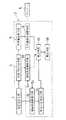
図1にこの発明の一実施例による歯科用予測模型の作成装置の構成を示す。この装置は、矯正対象の歯と顎堤の形状を電子データ化して取得する形状取得手段2と、取得された電子データから各歯の形状に応じて設定された所定基準に基づいて、モニター5上に三次元的に歯科用予測模型を構築する画像生成装置3とを備えている。
【0017】
この画像生成装置3は、取得された歯の形状に基づいて解剖学上の各歯の基準点(代表点)により各歯ごとの代表平面を生成する代表平面生成手段4と、代表平面に基づいて各歯の基準線(DI線,DH線)を生成する基準線生成手段6と、各歯の生成されたDH線の高さを一定高さに合わせるDH線高さ調整手段8と、顔面に設定した顔面基準線に対する各歯の生成された代表平面の傾斜角度を傾斜調整指令信号S1 を受けて調整する傾斜角度調整手段10とを備えている。
【0018】
また、画像生成装置3は、上下顎の前歯位置が互いに所定値以上ずれている場合に、前歯位置調整指令信号S2 を受けて、そのずれを適正に調整する前歯位置調整手段12と、調整された前歯位置に基づいて咬合平面を決定する咬合平面決定手段14と、決定された咬合平面に基づいて各歯のDH線高さまたは代表平面の傾斜角度を修正する修正手段16と、各歯ごとに上記基準点(代表点)と基準線(DI線,DH線)との顎堤上のずれを算出する算出手段18とを備えている。
【0019】
以下、この装置の動作を説明する。
1.[形状取得段階]
まず、患者の上下顎の印象が公知の印象材により採られる。この矯正前の歯と顎堤を再現した印象模型の形状が、例えばレーザ光などの光照射を用いた三次元計測装置である形状取得手段2によって、非接触で計測されて電子データ化される。ここで、顎堤とは、歯を支持する顎骨と粘膜とから形成されるものである。この三次元計測装置としては、例えばマルチスリットレーザとCCDカメラとによる多重露光高速計測装置やスリット光を複数回投影するパターン投影方式(光切断方式)計測装置などの従来から周知の装置が用いられるので、具体的な説明を省略する。
【0020】
これらの電子データが画像生成装置3に入力され、もとの歯と顎堤の模型がモニター5上に三次元的に構築される。この模型は、各歯の形状に応じて設定された所定基準に基づいて随時必要なデータが与えられて変更が加えられ、歯科用予測模型として作成される。
【0021】
2.[基準設定段階]
患者の歯と顎堤の形状に基づいて、基準となる各平面が設定される。図2に下顎(LOWER)の歯の排列モデルを示す。L1 〜L7 は下顎の歯の番号を示し、L1 は中切歯、L2 は側切歯、L3 は犬歯、L4 〜L5 は小臼歯、L6 〜L7 は大臼歯の番号を示す。また、L61は左第1大臼歯、L62は右第1大臼歯の番号を示す。なお、上顎(UPPER)の歯の番号についても同様にU1 〜U7 で示される。この図において、X軸は前歯(例えば、中切歯L1 )から模型後面に直交する方向を、Y軸は模型後面と平行な方向を、Z軸は紙面と垂直な方向を示す。
【0022】
まず、初期咬合平面KH1 が設定される。この初期咬合平面KH1 は、矯正前の歯の排列状態によって決定される初期の仮想平面で、下顎(Lower)については、中切歯L1 ,左右第1臼歯L61,L62のそれぞれ咬頭部または切縁部の代表点3点で、上顎(Upper)については、中切歯U1 、左右第1臼歯U61,U62のそれぞれ咬頭部または切縁部の代表点3点で構成される平面である(図7(A)参照)。咬頭部とは臼歯の歯冠咬合面の突起をいい、咬頭部の代表点とは犬歯では尖頭、臼歯(小臼歯,大臼歯)では頬側咬頭頂をさす。切縁部とは切歯切縁をさし、切縁部代表点とは前歯(中切歯,側切歯)ではその中点をいう。また、顎堤の形状に基づいて、顎堤の平面形状の輪郭データである顎堤平面GHも作成される(図3,図5参照)。次いで、顔面に設定した顔面基準線であるフランクフルト平面FHが設定される(図6〜8参照)。この歯科用予測模型に顎態模型を用いた場合には、模型底面に平行する面がフランクフルト平面として設定される。平行模型を用いた場合には、咬合面と模型底面が平行するので、模型底面(初期咬合平面)に対する左右、前後の傾斜角度でフランクフルト平面が設定される。
【0023】
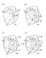
図3(A)にモニター5上に表示された歯の三次元モデルを示す。この表示された歯は、解剖学上の近心コンタクトポイントA1 ,遠心コンタクトポイントA2 の少なくとも1つを側面に含み歯の境界領域を示す多角柱状(例えば、六角柱状)に、顎堤平面GHを歯の底面として切り出されたものである。近遠心コンタクトポイントとは隣接する歯同士の接触点を意味し、このうち顔面の正中線に近い方を近心、遠い方を遠心という。解剖学上の近遠心コンタクトポイントA1 ,A2 とは、隣接する歯同士が接触すべき理想の点をいう。このポイントA1 とA2 間の距離が歯間幅Wになる。また、頬側歯頸点B1 と舌側歯頸点B2 も指定される。一般に頬または唇側は口腔内前側をいい、舌側は口腔内後側をいう。歯頸とは歯冠と歯根との移行部をいう。
【0024】
次に、図3(B)〜(D)において、上記の各基準点A1 ,A2 ,B1 ,B2 により、各歯ごとに、歯の形状の基準となる代表平面RP、DI線、およびDH線が生成される。
2−1.[代表平面生成工程]
まず、代表平面生成手段4により代表平面RPが生成される。図3(B)において、頬側歯頸点B1 と舌側歯頸点B2 間の中点Eが指定され、解剖学上の近心コンタクトポイントA1 と、遠心コンタクトポイントA2 と、この中点Eとにより形成される代表平面RPが生成される。この代表平面RPは、実際に各歯ごとに図1のモニター5上で線引される。
【0025】
2−2.[基準線生成工程]
次に、図3(C)に示すように、基準線生成手段6により、上記頬側歯頸点B1 と咬頭部または切縁部の代表点Cとを結ぶ直線を代表平面RPに投影したDI線が生成される。そして、図3(D)において、このDI線と上記代表点Cから所定距離hだけ顎堤側にずらした点で直交するDH線が生成される。図4に示すように、この所定距離hは歯ごとに異なる経験値であり、この値を初期値として一旦決定され後に修正される場合がある。これらDI線,DH線も実際に各歯ごとにモニター5上に線引される。なお、各歯のDH線の長さは各歯の歯間幅Wを示す。このようにして、各歯の形状に応じて基準が設定され、これらの基準に基づいて、歯科用予測模型が作成される。
【0026】
3.[模型作成段階]
まず、上下顎の基準となるセンターラインが決定される。図5(A)に示すように、モニター5上に、上下顎の顎堤平面GH上に各歯のDH線が表示される。上下顎は模型後面に対して見開きの状態で表示される。この場合、顔面の正中線または上下顎のレントゲン写真により、上下顎のセンターと判断される前歯付近のポイントP1 ,P2 からそれぞれ模型後面と直交するようにラインが引かれ、上顎のライン上に下顎のラインがくるように下顎の歯列弓が移動される。この仮のセンターラインO1 に対して、第1大臼歯L61の左右対称点となるL62が求められる。このL62が顎堤平面GH上をはずれるような場合には、仮のセンターラインO1 をO2 にずらしてL62が顎堤平面GH上にくるようにする。このO2 が上下顎のセンターラインになる。なお、左右第1大臼歯L61,L62が図5(B)のように顎堤平面GHに対して傾いているような場合には、これに応じてセンターラインO2 を回転させる必要がある。こうして、最終的なセンターラインO2 が決定される。
【0027】
3−1.[前歯位置調整工程]
ところで、上下顎前歯の咬み合わせに大きなずれがある場合がある。図6(A)の側面図において、例えば下顎中切歯L1の先端と上顎中切歯U1の先端との垂直方向のずれをオーバーバイト(OB)といい、水平方向のずれをオーバージェット(OJ)という。適正なオーバーバイト値は約2mm、オーバージェット値も約2mmである。患者の上下顎前歯がこの値を大きく越えてずれているような場合にはその位置を矯正する必要がある。この場合、前歯位置調整手段12により、上下顎の前歯の位置が適正なオーバージェット値およびオーバーバイト値になるように、前歯位置調整指令信号S2 を受けて、上顎前歯の切縁部の代表点Cの位置と下顎前歯の切縁部の代表点Cの位置との少なくとも一方が、以下のように調整される。
【0028】
まず、図6(A)において、上顎の中切歯U1 について、その切縁部の代表点Cと中点Eとを結ぶ中心線CE−1線上に位置する切縁部の代表点C,頬側歯頸点B1 ,および舌側歯頸点B2 からなる中央輪郭線が抽出される。下顎の中切歯L1 についても同様に、下顎の中切歯L1 の切縁部の代表点Cと中点Eとを結ぶ中心線CE−2線上に位置する中央輪郭線が抽出される。図6(B)において、矯正前の上下顎の中切歯U1 ,L1 のCE−1,CE−2線が、フランクフルト平面FHとともに表示される。この図により、上下顎の中切歯U1 ,L1 のオーバーバイト(OB)値,オーバージェット(OJ)値,及びフランクフルト平面FHとCE−1,CE−2線のなす角度が示される。以下、この図に基づいて、上下顎の中切歯U1 ,L1 の位置が調整される。
【0029】
下顎の中切歯L1 の矯正位置は、例えばレントゲン写真からの顎骨構造などを考慮して決められる。この場合、図7(A)に示すように、中切歯L1 の切縁部の代表点Cの位置からX方向にxmm,Z方向にzmm移動した新代表点C1 が、下顎の初期咬合平面KH1 を基準にして指定される。なお、必要に応じてY方向にも移動される。また、中切歯L1 のCE−2線とフランクフルト平面FHとのなす角度βも指定される。この前歯位置調整指令信号S2 に基づいて、点線部のように下顎の中切歯L1 の位置が決定される。
【0030】
次に、上顎の中切歯U1 の位置が決められる。この場合、図8(A)に示すように、上下顎の中切歯U1 ,L1 が適正なオーバージェット(OJ)値およびオーバーバイト(OB)値になるように移動点が指定され、また、中切歯U1 のCE−1線とフランクフルト平面FHとのなす角度γが指定される。この場合、上下顎の中切歯U1 ,L1 の外形線が互いに重ならないように干渉チェックが行われる。
【0031】
3−2.[咬合平面決定工程]
図7(A)に示すように、下顎の中切歯L1 の位置が点線部に変更されることにより、初期咬合平面KH1 から新咬合平面KH2 に変更される。すなわち、咬合平面決定手段14により、下顎前歯L1 の切縁部の代表点Cが調整された位置と、形状取得手段2で得られた下顎の左右第1大臼歯L61,L62の咬頭部の代表点Cの位置とにより形成される下顎の新しい咬合平面KH2 が決定される。そして、図7(B)のように、この下顎の新咬合平面KH2 を基準にして下顎のDH平面が決定される。
【0032】
また、図8(A)のように、上顎の中切歯U1 の位置が点線部に変更されると、同様に、上顎の新咬合平面KH2 に変更される。すなわち、咬合平面決定手段14により、上顎前歯U1 の切縁部の代表点Cが調整された位置と、形状取得手段2で得られた上顎の左右第1大臼歯U61,U62の咬頭部の代表点Cの位置とにより形成される上顎の新しい咬合平面KH2 が決定される。そして、図8(B)のように、この上顎の新咬合平面KH2 を基準にして上顎のDH平面が決定される。
【0033】
こうして、上下顎の新咬合平面KH2 が作成される。もちろん、矯正前の上下顎の前歯のオーバーバイト,オーバージェット値が適正であれば、前歯の位置は調整されず、初期咬合平面KH1 が維持される。
【0034】
なお、上下顎の前歯の位置を調整する必要がなく左右第1大臼歯L61,L62の位置を調整する必要があるときには、その変更位置により新咬合平面KH2 が決定され、上下顎のDH平面が決定される。
【0035】
また、抜歯する必要がある歯があれば、歯の番号L1 〜L7 ,U1 〜U7 を指定する。また、歯が抜けている場合には補綴する歯のスペースが確保される。
【0036】
3−3.[排列工程]
次に、歯のDH線を排列するために、顎堤の平面形状を示すガイドラインが決定される。まず、前歯のDH線を排列するアーチ部分が決められる。図9(A)は下顎を代表として示しており、上記センターラインO2 上に、片側の中切歯L1 ,側切歯L2 ,犬歯L3 のDH線の長さ(歯の幅)Wの総和をアーチ半径Rにして、上下顎の前歯のセンターポイントPを通る円が描かれる。この円に沿って、両側に中切歯L1 ,側切歯L2 ,犬歯L3 のDH線が置かれ、犬歯L3 のDH線の末端点と左右第1大臼歯L61,L62とがそれぞれ直線で結ばれる。上顎についても同様にしてガイドラインを作成し、こうして作成された上下顎のガイドラインUG,LGは、図9(B)に示すように、互いに重ね合わされて、ラインの干渉がチェックされる。この図において、上顎のガイドラインUGは実線で、下顎のガイドラインLGは破線で示される。この干渉チェック後に最終的なガイドラインが決定される。そして、図10の平面図に示すように、この決定されたガイドラインLG(UG)に沿って平面上に、それぞれDH線の長さ(歯の幅)Wによって示される各歯が排列される。
【0037】
このように、個々の歯をDH線に置き換えてガイドラインLG(UG)上に排列することにより、短時間で正確に各歯の排列を行うことができる。また、排列に要するデータ量もDH線のデータだけであるので三次元面形状のデータ量に比較して少なく済む。
【0038】
3−4.[DH線高さ調整工程]
次に、DH線高さ調整手段8により、図11に示すように、ガイドラインLGに沿って平面上に並べられた各歯のDH線の高さが一定高さに合わせられる。この高さは前述したDH平面の高さに相当する。上記のように、上下顎の咬合平面が変更された場合には、このDH平面の高さが修正手段16により修正される。
【0039】
3−5.[傾斜角度調整工程]
また、傾斜角度調整手段10により各歯の傾斜角度が調整される。ここで、傾斜角度αとは、図12に示すように、顔面に設定した顔面基準線(フランクフルト平面)FHがその垂直面FHVと直交する直線FHLに対して、歯の代表平面RPがその垂直面RPVと直交する直線RPLがなす角度をいう。各歯ごとに、矯正前の傾斜角度αに対する矯正目標値が予め決められている。この各歯の矯正目標値に応じて出力される傾斜調整指令信号S1 を受けて、傾斜角度調整手段10により、モニター5上にその歯の矯正目標値になるように各歯の傾斜角度αが調整される。同様に、上下顎の咬合平面が変更された場合には、この調整された各歯の代表平面の傾斜角度αが修正手段16により修正される。
【0040】
3−6.[三次元形状生成工程]
なお、個々の歯のDH線による排列だけでは、上下顎の咬合状況の判断が困難な場合には、上記排列工程により排列された個々の歯に1.[形状取得工程]で得られた三次元面形状を付与して、三次元面形状の各歯の排列が図1のモニター5上に生成される。
【0041】
3−7.[咬合確認工程]
モニター5上で、三次元面形状を有する上下顎の歯を咬合させて、上下顎個々の歯の接触面積を求め、これら接触面積により上下顎の咬合状況が確認される。この際、必要があれば、接触面積が最小になるように、個々の歯の再排列が行われる。
【0042】
3−8.[歯列弓移動工程]
また、確認された咬合状況によって適切な上下顎被蓋関係が得られないと判断された場合には、モニター5上で下顎歯列弓全体を、適切な上下顎被蓋関係になるように三次元的に移動する(3.[模型作成段階]における下顎歯列弓の左右の移動も含む)ことも考慮される。この移動は外科的矯正治療をシュミレーションしたものである。
【0043】
なお、算出手段18により、各歯ごとに、図3(D)の解剖学上の近心コンタクトポイントA1 ,遠心コンタクトポイントA2 ,頬側歯頸点B1 ,舌側歯頸点B2 または咬頭部(切縁部)の代表点Cを含む歯の基準点(代表点)と、上記DI線またはDH線の歯の基準線との顎堤上のずれが算出される。このずれは予測模型の形状を示すものである。また、歯列弓移動工程における下顎歯列弓の移動量も算出される。これにより、歯科用予測模型がデータ化される。
【0044】
なお、この実施例では、この予測模型を歯科矯正用に作成しているが、データベースに記憶された各歯のデータに基づいて義歯作成用に作成してもよい。
【0045】
このようにして、モニター5上で、歯科治療に用いられる予測模型が容易に作成される。
【図面の簡単な説明】
【図1】この発明の一実施例に係る歯科矯正用模型の作成装置を示す構成図である。
【図2】歯の排列モデルを示す平面図である。
【図3】歯の三次元モデルを示す斜視図である。
【図4】DH線の高さを示す図である。
【図5】矯正前における上下顎の顎堤平面上の歯の排列を示す平面図である。
【図6】上下顎前歯のオーバーバイト,オーバージェットを示す側面図である。
【図7】下顎の前歯を示す側面図である。
【図8】上顎の前歯を示す側面図である。
【図9】ガイドラインを示す平面図である。
【図10】各歯の排列状態を示す平面図である。
【図11】各歯のDH線の高さが一定になった状態を示す斜視図である。
【図12】各歯の傾斜角度を示す斜視図である。
【符号の説明】
2…形状取得手段、4…代表平面生成手段、6…基準線生成手段、8…DH線高さ調整手段、10…傾斜角度調整手段。[0001]
[Industrial application fields]
The present invention relates to a method and apparatus for creating a predicted dental model used for dental treatment, and relates to facilitation thereof.
[0002]
[Prior art]
In general, in dental treatments such as orthodontics and denture creation, a prediction model is often created based on an impression model that takes the impression of a patient's teeth and ridge. This prediction model is created by cutting out individual teeth on the jaw ridge of the impression model one by one and performing rearrangement. With this created prediction model, the final goal of dental treatment becomes clear, and the occlusal state of the upper and lower jaws can be specifically confirmed.
[0003]
Moreover, since the patient can visually recognize the final state of the dental treatment by showing the prediction model, it is preferable from the psychological viewpoint of the patient.
[0004]
[Problems to be solved by the invention]
However, since the conventional prediction model is created manually, it is complicated and time-consuming. Further, when a plurality of means for achieving the goal of dental treatment are conceivable, this work becomes extremely complicated, and it has become a problem that time saving and labor saving are strongly desired.
[0005]
An object of the present invention is to provide a dental prediction model creation method and creation apparatus that can solve the above-described problems and can easily create a prediction model.
[0006]
[Means for Solving the Problems]
In order to achieve the above-mentioned object, the invention of
[0007]
Further, if necessary, an occlusal plane of the upper jaw formed by the position of the representative point C of the maxillary anterior tooth from which the tooth shape is acquired and the position of the representative point C of the left and right first molars of the upper jaw, and The occlusal plane of the lower jaw formed by the position of the representative point C of the lower anterior tooth from which the tooth shape is acquired and the position of the representative point C of the left and right first molars of the lower jaw is determined. Then, based on the determined occlusal plane of the upper and lower jaws, the height of the DH line of each tooth or the inclination angle of the representative plane of each tooth is corrected.
[0008]
Furthermore, if necessary, the position of the representative point C of the maxillary anterior tooth and the position of the representative point C of the mandibular anterior tooth so that predetermined overjet values and overbite values can be obtained between the maxillary anterior teeth and the mandibular anterior teeth. Adjust at least one. The upper occlusal plane formed by the position of the representative point C of the upper maxillary anterior tooth and the position of the representative point C of the left and right first molars of the upper jaw from which the above-mentioned shape was acquired, and the adjusted lower jaw A mandibular occlusal plane formed by the position of the representative point C of the anterior teeth and the position of the representative point C of the left and right first molars of the lower jaw from which the above shape has been acquired is determined. Then, based on the determined occlusal plane of the upper and lower jaws, the height of the DH line of each tooth or the inclination angle of the representative plane of each tooth is corrected.
[0009]
If necessary, for each tooth, the deviation on the ridge between the representative point of the tooth including A1, A2, B1, B2 or C and the reference line of the DI line or DH line is calculated. .
[0010]
Furthermore, if necessary, a three-dimensional surface shape obtained by acquiring the tooth shape is added to each tooth arranged by the DH line to generate a three-dimensional surface shape tooth arrangement. The upper and lower jaw teeth having a surface shape are occluded, the occlusal situation is confirmed by the contact area of the upper and lower jaw teeth, and the entire lower jaw dental arch is moved so as to obtain an appropriate upper and lower jaw covering relationship. The amount of movement is calculated.
[0011]
[Action and effect]
According to the present invention, the anatomical mesial contact point A1, the distal contact point A2, and the midpoint E between the buccal tooth neck point B1 and the lingual tooth neck point B2 are formed on the electronic data for each tooth. And a DI line obtained by projecting a straight line connecting the buccal side neck point B1 and the representative point C of the cusp or the incisal edge onto the representative plane for each tooth, A perpendicular DH line is generated at a point shifted from the representative point C by a predetermined distance toward the ridge. Then, the height of the DH line of each tooth arranged on the plane according to the guideline indicating the planar shape of the jaw ridge is adjusted to a constant height, and the representative plane of each tooth with respect to the face reference line set on the face is set. Adjust the tilt angle. Therefore, it is easy to create a dental prediction model.
[0012]
Further, if necessary, the occlusal plane of the patient's upper and lower jaws is determined on the electronic data, and the height of the DH line of each tooth or the inclination angle of the representative plane of each tooth is corrected based on this occlusal plane. Therefore, it becomes easy to create a dental prediction model in accordance with the shape of the patient's teeth and ridge.
[0013]
Furthermore, if the overjet and overbite exceed the prescribed values between the maxillary anterior teeth and the mandibular anterior teeth, adjust the position of the upper and lower jaw anterior teeth and adjust the occlusal plane of the upper and lower jaws as necessary. Based on this occlusal plane, the height of the DH line of each tooth or the inclination angle of the representative plane of each tooth is corrected. Therefore, even when the occlusion of the upper and lower jaw front teeth is not preferable, it is easy to create a dental prediction model according to the shape of the patient's teeth and the jaw ridge.
[0014]
If necessary, for each tooth, the deviation on the ridge between the representative point of the tooth including A1, A2, B1, B2 or C and the reference line of the DI line or DH line is calculated. . Therefore, post-correction data of the dental prediction model can be easily obtained.
[0015]
Furthermore, if necessary, a three-dimensional surface shape obtained by acquiring the tooth shape is added to each tooth arranged by the DH line to generate a three-dimensional surface shape tooth arrangement. The upper and lower jaw teeth having a surface shape are occluded, the occlusal situation is confirmed by the contact area of the upper and lower jaw teeth, and the entire lower jaw dental arch is moved so as to obtain an appropriate upper and lower jaw covering relationship. The amount of movement is calculated. Therefore, it is possible to check the occlusal state of the upper and lower jaws using teeth having a three-dimensional surface shape, and to move the entire lower dentition arch so as to have an appropriate upper and lower jaw covering relationship. This makes it easy to create a dental prediction model according to the occlusal condition of the patient.
[0016]
【Example】
Embodiments of the present invention will be described below with reference to the drawings.
FIG. 1 shows the configuration of a dental prediction model creating apparatus according to an embodiment of the present invention. This apparatus is based on a shape acquisition means 2 for acquiring the shape of teeth to be corrected and the shape of the jaw ridge as electronic data, and a
[0017]
The
[0018]
Further, the
[0019]
The operation of this apparatus will be described below.
1. [Shape acquisition stage]
First, the patient's upper and lower jaw impression is taken with a known impression material. The shape of the impression model that reproduces the teeth and ridges before correction is measured in a non-contact manner and converted into electronic data by the shape acquisition means 2 which is a three-dimensional measuring device using light irradiation such as laser light. . Here, the jaw ridge is formed from a jawbone and a mucous membrane that support teeth. As this three-dimensional measuring apparatus, conventionally known apparatuses such as a multi-exposure high-speed measuring apparatus using a multi-slit laser and a CCD camera and a pattern projection method (light cutting method) measuring device that projects slit light a plurality of times are used. Therefore, a specific description is omitted.
[0020]
These electronic data are input to the
[0021]
2. [Standard setting stage]
Each plane as a reference is set based on the shape of the patient's teeth and ridge. FIG. 2 shows a lower teeth (LOWER) tooth arrangement model. L1 to L7 indicate the number of the lower jaw tooth, L1 represents the central incisor, L2 represents the side incisor, L3 represents the canine, L4 to L5 represents the premolar, and L6 to L7 represents the molar number. L61 represents the number of the left first molar, and L62 represents the number of the right first molar. The upper jaw (UPPER) tooth numbers are also indicated by U1 to U7. In this figure, the X axis indicates a direction perpendicular to the rear surface of the model from the front tooth (for example, the central incisor L1), the Y axis indicates a direction parallel to the rear surface of the model, and the Z axis indicates a direction perpendicular to the paper surface.
[0022]
First, an initial occlusal plane KH1 is set. This initial occlusal plane KH1 is an initial virtual plane determined by the arrangement of the teeth before correction. For the lower jaw, the central incisor L1 and the left and right first molars L61 and L62 are respectively the head or incision The upper jaw is a plane composed of three representative points of the central incisor U1 and the left and right first molars U61 and U62, respectively. (See (A)). The cusp is the protrusion of the molar occlusal surface of the molar, and the representative point of the cusp is the apex of the canine and the buccal cusp of the molar (molar, molar). The incision portion refers to the incisor incision, and the incision portion representative point refers to the midpoint of the front teeth (medium incisors and side incisors). Further, based on the shape of the ridge, a ridge plane GH which is contour data of the planar shape of the ridge is also created (see FIGS. 3 and 5). Next, the Frankfurt plane FH, which is the face reference line set for the face, is set (see FIGS. 6 to 8). When a jaw model is used as the dental prediction model, a plane parallel to the model bottom is set as the Frankfurt plane. When the parallel model is used, the occlusal surface and the model bottom surface are parallel to each other, so that the Frankfurt plane is set with the left and right and front and rear inclination angles with respect to the model bottom surface (initial occlusion plane).
[0023]
FIG. 3A shows a three-dimensional model of teeth displayed on the
[0024]
Next, in FIGS. 3B to 3D, the reference planes RP, DI line, and DH line that serve as a reference for the tooth shape for each tooth by the reference points A1, A2, B1, and B2 described above. Is generated.
2-1. [Representative plane generation process]
First, the representative
[0025]
2-2. [Baseline generation process]
Next, as shown in FIG. 3C, the reference line generating means 6 projects a straight line connecting the buccal tooth neck point B1 and the representative point C of the cusp or incision onto the representative plane RP. A line is generated. In FIG. 3D, a DH line that is orthogonal to the DI line at a point shifted from the representative point C by a predetermined distance h toward the jaw bank is generated. As shown in FIG. 4, the predetermined distance h is an empirical value that is different for each tooth, and this value may be once determined as an initial value and corrected later. These DI and DH lines are also drawn on the
[0026]
3. [Model creation stage]
First, a center line serving as a reference for the upper and lower jaws is determined. As shown in FIG. 5A, the DH line of each tooth is displayed on the
[0027]
3-1. [Front tooth position adjustment process]
By the way, there are cases where there is a large deviation in the occlusion of the upper and lower jaw front teeth. In the side view of FIG. 6A, for example, the vertical deviation between the distal end of the lower central incisor L1 and the distal end of the upper central incisor U1 is called overbite (OB), and the horizontal deviation is overjet (OJ). ). The proper overbite value is about 2 mm, and the overjet value is also about 2 mm. If the patient's upper and lower jaw front teeth are displaced far beyond this value, the position needs to be corrected. In this case, the front tooth position adjusting means 12 receives the front tooth position adjustment command signal S2 so that the positions of the front teeth of the upper and lower jaws become appropriate overjet values and overbite values, and the representative point of the incisal portion of the upper front teeth At least one of the position of C and the position of the representative point C of the incisal edge of the mandibular front tooth is adjusted as follows.
[0028]
First, in FIG. 6A, for the central incisor U1 of the upper jaw, the representative point C and cheek of the incision located on the center line CE-1 line connecting the representative point C of the incision and the midpoint E. A central outline consisting of the side tooth neck point B1 and the lingual tooth neck point B2 is extracted. Similarly, for the central incisor L1 of the lower jaw, the central contour line located on the center line CE-2 connecting the representative point C and the middle point E of the incision portion of the central incisor L1 of the lower jaw is extracted. In FIG. 6B, the CE-1 and CE-2 lines of the central incisors U1 and L1 of the upper and lower jaws before correction are displayed together with the Frankfurt plane FH. This figure shows the overbite (OB) value and overjet (OJ) value of the central incisors U1 and L1 of the upper and lower jaws, and the angle formed by the Frankfurt plane FH and the CE-1 and CE-2 lines. Hereinafter, the positions of the central incisors U1 and L1 of the upper and lower jaws are adjusted based on this figure.
[0029]
The correction position of the central incisor L1 of the lower jaw is determined in consideration of, for example, the jawbone structure from the X-ray photograph. In this case, as shown in FIG. 7A, the new representative point C1 moved by xmm in the X direction and zmm in the Z direction from the position of the representative point C of the cutting edge of the central incisor L1 is the initial occlusal plane of the lower jaw. Specified based on KH1. It is also moved in the Y direction as necessary. Further, an angle β formed by the CE-2 line of the central incisor L1 and the Frankfurt plane FH is also designated. Based on the front tooth position adjustment command signal S2, the position of the lower central incisor L1 is determined as indicated by the dotted line.
[0030]
Next, the position of the maxillary central incisor U1 is determined. In this case, as shown in FIG. 8 (A), the moving points are designated so that the central incisors U1 and L1 of the upper and lower jaws have appropriate overjet (OJ) and overbite (OB) values, An angle γ formed by the CE-1 line of the central incisor U1 and the Frankfurt plane FH is designated. In this case, an interference check is performed so that the contour lines of the central incisors U1 and L1 of the upper and lower jaws do not overlap each other.
[0031]
3-2. [Occlusal plane determination process]
As shown in FIG. 7A, when the position of the central incisor L1 of the lower jaw is changed to the dotted line portion, the initial occlusal plane KH1 is changed to the new occlusal plane KH2. That is, the position where the representative point C of the incisal edge of the mandibular anterior tooth L1 is adjusted by the occlusal
[0032]
Further, as shown in FIG. 8A, when the position of the central incisor U1 of the upper jaw is changed to the dotted line, it is similarly changed to the new occlusal plane KH2 of the upper jaw. That is, the position where the representative point C of the incision edge of the maxillary anterior tooth U1 is adjusted by the occlusal
[0033]
Thus, a new occlusal plane KH2 for the upper and lower jaws is created. Of course, if the overbite and overjet values of the front and lower jaw teeth before correction are appropriate, the position of the front teeth is not adjusted and the initial occlusal plane KH1 is maintained.
[0034]
When it is necessary to adjust the positions of the left and right first molars L61 and L62 without adjusting the position of the front teeth of the upper and lower jaws, the new occlusal plane KH2 is determined according to the changed position, and the DH plane of the upper and lower jaws is determined. It is determined.
[0035]
If there are teeth that need to be extracted, the tooth numbers L1 to L7 and U1 to U7 are designated. Further, when the teeth are missing, a space for the prosthetic teeth is secured.
[0036]
3-3. [Arrangement process]
Next, in order to arrange the DH lines of the teeth, a guideline indicating the planar shape of the jaw ridge is determined. First, an arch portion for arranging the DH lines of the front teeth is determined. FIG. 9A shows the lower jaw as a representative. The total sum of the lengths (tooth widths) W of the DH lines of the central incisor L1, side incisor L2, and canine L3 on one side is shown on the center line O2. A circle that passes through the center point P of the front teeth of the upper and lower jaws is drawn with the arch radius R. Along this circle, the DH lines of the central incisor L1, the side incisor L2, and the canine L3 are placed on both sides, and the end point of the DH line of the canine L3 and the left and right first molars L61 and L62 are connected by straight lines, respectively. It is. A guideline is created in the same manner for the upper jaw, and the upper and lower jaw guidelines UG and LG created in this manner are overlapped with each other as shown in FIG. In this figure, the upper jaw guideline UG is indicated by a solid line, and the lower jaw guideline LG is indicated by a broken line. Final guidelines are determined after this interference check. Then, as shown in the plan view of FIG. 10, the teeth indicated by the length (tooth width) W of the DH line are arranged on the plane along the determined guide line LG (UG).
[0037]
Thus, by replacing individual teeth with DH lines and arranging them on the guide line LG (UG), it is possible to arrange each tooth accurately in a short time. Further, since the amount of data required for arrangement is only DH line data, the amount of data can be reduced compared to the data amount of the three-dimensional surface shape.
[0038]
3-4. [DH line height adjustment process]
Next, as shown in FIG. 11, the DH line height adjusting means 8 adjusts the height of the DH line of each tooth arranged on the plane along the guide line LG to a constant height. This height corresponds to the height of the DH plane described above. As described above, when the occlusal planes of the upper and lower jaws are changed, the height of the DH plane is corrected by the correcting means 16.
[0039]
3-5. [Inclination angle adjustment process]
Further, the inclination angle adjustment means 10 adjusts the inclination angle of each tooth. Here, as shown in FIG. 12, the inclination angle α means that the facial reference line (Frankfurt plane) FH set on the face is perpendicular to the straight line FHL perpendicular to the vertical plane FHV. An angle formed by a straight line RPL orthogonal to the surface RPV. The correction target value for the inclination angle α before correction is determined in advance for each tooth. In response to the inclination adjustment command signal S1 output in accordance with the correction target value of each tooth, the inclination angle adjustment means 10 determines the inclination angle α of each tooth on the
[0040]
3-6. [Three-dimensional shape generation process]
In addition, when it is difficult to determine the occlusal state of the upper and lower jaws only by arranging the individual teeth by DH line, the individual teeth arranged by the above-described arrangement process are 1. By assigning the three-dimensional surface shape obtained in the [shape acquisition step], an arrangement of each tooth of the three-dimensional surface shape is generated on the
[0041]
3-7. [Occlusion confirmation process]
On the
[0042]
3-8. [Dental arch movement process]
Further, when it is determined that an appropriate upper and lower jaw covering relationship cannot be obtained due to the confirmed occlusion, the entire lower jaw dental arch is placed on the
[0043]
The calculating means 18 uses the anatomical mesial contact point A1, the centrifugal contact point A2, the buccal side neck point B1, the lingual side neck point B2 or the cusp (see FIG. 3D) for each tooth. The deviation on the ridge of the tooth reference point (representative point) including the representative point C of the (edge) and the tooth reference line of the DI line or DH line is calculated. This deviation indicates the shape of the prediction model. Further, the amount of movement of the lower dental arch in the dental arch movement process is also calculated. Thereby, the dental prediction model is converted into data.
[0044]
In addition, in this Example, although this prediction model is created for orthodontics, you may create for denture creation based on the data of each tooth memorize | stored in the database.
[0045]
In this way, a prediction model used for dental treatment is easily created on the
[Brief description of the drawings]
FIG. 1 is a configuration diagram showing an orthodontic model creation apparatus according to an embodiment of the present invention.
FIG. 2 is a plan view showing a tooth arrangement model.
FIG. 3 is a perspective view showing a three-dimensional model of teeth.
FIG. 4 is a diagram showing the height of a DH line.
FIG. 5 is a plan view showing the arrangement of teeth on the upper and lower jaw ridge plane before correction.
FIG. 6 is a side view showing overbite and overjet of upper and lower jaw front teeth.
FIG. 7 is a side view showing anterior teeth of the lower jaw.
FIG. 8 is a side view showing anterior teeth of the upper jaw.
FIG. 9 is a plan view showing guidelines.
FIG. 10 is a plan view showing an arrangement state of each tooth.
FIG. 11 is a perspective view showing a state in which the height of the DH line of each tooth is constant.
FIG. 12 is a perspective view showing an inclination angle of each tooth.
[Explanation of symbols]
2 ... shape acquisition means, 4 ... representative plane generation means, 6 ... reference line generation means, 8 ... DH line height adjustment means, 10 ... inclination angle adjustment means.
Claims (4)
Translated fromJapanese電子データ上で、個々に多角柱状に切り出された各歯ごとに、解剖学上の近心コンタクトポイントA1 ,遠心コンタクトポイントA2 ,および頬側歯頸点B1 と舌側歯頸点B2 の中点Eにより形成される代表平面を生成する代表平面生成手段、
上記頬側歯頸点B1 と咬頭部または切縁部の代表点Cとを結ぶ直線を上記代表平面に投影したDI線と、このDI線と上記代表点Cから所定距離下げた点で直交するDH線を生成する基準線生成手段、
顎堤の平面形状を示すガイドラインに沿って平面上に並べられた各歯のDH線の高さを一定高さに合わせるDH線高さ調整手段、および、
傾斜調整指令信号を受けて、顔面に設定した顔面基準線に対する各歯の代表平面の傾斜角度を調整する傾斜角度調整手段を有する歯科用予測模型の作成装置。Shape acquisition means for obtaining the shape of the teeth and ridges converted into electronic data by obtaining the shape of the impression model reproducing the patient's teeth and ridges in a non-contact manner by a three-dimensional measuring device using light irradiation,
In the electronic data, for each tooth cut into a polygonal column, the anatomical mesial contact point A1, the distal contact point A2, and the midpoint of the buccal and cervical points B1 and B2 Representative plane generating means for generating a representative plane formed by E,
A DI line obtained by projecting a straight line connecting the buccal tooth neck point B1 and the representative point C of the cusp or incision onto the representative plane is orthogonal to the DI line at a point lowered by a predetermined distance from the representative point C. A reference line generating means for generating a DH line;
DH line height adjusting means for adjusting the height of the DH line of each tooth arranged on the plane along the guideline indicating the planar shape of the jaw ridge to a constant height; and
An apparatus for creating a predicted dental model having an inclination angle adjusting means for receiving an inclination adjustment command signal and adjusting an inclination angle of a representative plane of each tooth with respect to a facial reference line set on the face.
決定された上下顎の咬合平面に基づいて、各歯のDH線の高さまたは各歯の代表平面の傾斜角度を修正する修正手段とを有する歯科用予測模型の作成装置。2. The upper occlusal plane formed by the position of the representative point C of the maxillary anterior tooth and the position of the representative point C of the left and right first molars obtained by the shape acquiring means according toclaim 1 , and the shape acquisition Occlusal plane determining means for determining the occlusal plane of the lower jaw formed by the position of the representative point C of the lower anterior teeth obtained by the means and the position of the representative point C of the left and right first molars of the lower jaw;
An apparatus for creating a predicted dental model having correction means for correcting the height of the DH line of each tooth or the inclination angle of the representative plane of each tooth based on the determined occlusal plane of the upper and lower jaws.
上記調整された上顎前歯の代表点Cの位置と形状取得手段で得られた上顎の左右第1大臼歯の代表点Cの位置とにより形成される上顎の咬合平面、および、上記調整された下顎前歯の代表点Cの位置と上記形状取得手段で得られた下顎の左右第1大臼歯の代表点Cの位置とにより形成される下顎の咬合平面を決定する咬合平面決定手段と、
決定した上下顎の咬合平面に基づいて、各歯のDH線の高さまたは各歯の代表平面の傾斜角度を修正する修正手段とを有する歯科用予測模型の作成装置。In claim 1 , the position of the representative point C of the maxillary anterior teeth and the position of the mandibular anterior teeth are received by receiving the anterior tooth position adjustment command signal so that predetermined overjet values and overbite values are obtained between the maxillary anterior teeth and the mandibular anterior teeth. Anterior tooth position adjusting means for adjusting at least one of the position of the representative point C;
The occlusal plane of the upper jaw formed by the position of the representative point C of the maxillary anterior tooth and the position of the representative point C of the left and right first molars obtained by the shape acquisition means, and the adjusted mandible Occlusal plane determining means for determining the occlusal plane of the lower jaw formed by the position of the representative point C of the anterior teeth and the position of the representative point C of the left and right first molars of the lower jaw obtained by the shape acquisition means;
An apparatus for creating a dental prediction model, comprising correction means for correcting the height of the DH line of each tooth or the inclination angle of the representative plane of each tooth based on the determined occlusal plane of the upper and lower jaws.
Priority Applications (2)
| Application Number | Priority Date | Filing Date | Title |
|---|---|---|---|
| JP11379095AJP3672966B2 (en) | 1995-04-14 | 1995-04-14 | Method and apparatus for creating dental prediction model |
| US08/522,458US5605459A (en) | 1995-04-14 | 1995-08-31 | Method of and apparatus for making a dental set-up model |
Applications Claiming Priority (1)
| Application Number | Priority Date | Filing Date | Title |
|---|---|---|---|
| JP11379095AJP3672966B2 (en) | 1995-04-14 | 1995-04-14 | Method and apparatus for creating dental prediction model |
Publications (2)
| Publication Number | Publication Date |
|---|---|
| JPH08280715A JPH08280715A (en) | 1996-10-29 |
| JP3672966B2true JP3672966B2 (en) | 2005-07-20 |
Family
ID=14621162
Family Applications (1)
| Application Number | Title | Priority Date | Filing Date |
|---|---|---|---|
| JP11379095AExpired - Fee RelatedJP3672966B2 (en) | 1995-04-14 | 1995-04-14 | Method and apparatus for creating dental prediction model |
Country Status (2)
| Country | Link |
|---|---|
| US (1) | US5605459A (en) |
| JP (1) | JP3672966B2 (en) |
Cited By (3)
| Publication number | Priority date | Publication date | Assignee | Title |
|---|---|---|---|---|
| WO2018175486A1 (en)* | 2017-03-20 | 2018-09-27 | Align Technology, Inc. | Generating a virtual depiction of an orthodontic treatment of a patient |
| KR20180113275A (en)* | 2017-04-06 | 2018-10-16 | 정연호 | Method for generating bending path of tooth straitening wire |
| CN109646129A (en)* | 2019-02-26 | 2019-04-19 | 四川大学 | A kind of manufacturing method of personalized ceramic bracket appliance |
Families Citing this family (329)
| Publication number | Priority date | Publication date | Assignee | Title |
|---|---|---|---|---|
| US5823778A (en)* | 1996-06-14 | 1998-10-20 | The United States Of America As Represented By The Secretary Of The Air Force | Imaging method for fabricating dental devices |
| IL120867A0 (en)* | 1997-05-20 | 1997-09-30 | Cadent Ltd | Computer user interface for orthodontic use |
| IL120892A (en)* | 1997-05-22 | 2000-08-31 | Cadent Ltd | Method for obtaining a dental occlusion map |
| US6409504B1 (en)* | 1997-06-20 | 2002-06-25 | Align Technology, Inc. | Manipulating a digital dentition model to form models of individual dentition components |
| AU744385B2 (en)* | 1997-06-20 | 2002-02-21 | Align Technology, Inc. | Method and system for incrementally moving teeth |
| US7063532B1 (en) | 1997-06-20 | 2006-06-20 | Align Technology, Inc. | Subdividing a digital dentition model |
| US8496474B2 (en)* | 1997-06-20 | 2013-07-30 | Align Technology, Inc. | Computer automated development of an orthodontic treatment plan and appliance |
| US6705863B2 (en)* | 1997-06-20 | 2004-03-16 | Align Technology, Inc. | Attachment devices and methods for a dental appliance |
| US7247021B2 (en)* | 1997-06-20 | 2007-07-24 | Align Technology, Inc. | Subdividing a digital dentition model |
| US6471511B1 (en) | 1997-06-20 | 2002-10-29 | Align Technology, Inc. | Defining tooth-moving appliances computationally |
| US5975893A (en) | 1997-06-20 | 1999-11-02 | Align Technology, Inc. | Method and system for incrementally moving teeth |
| US6450807B1 (en)* | 1997-06-20 | 2002-09-17 | Align Technology, Inc. | System and method for positioning teeth |
| US6152731A (en)* | 1997-09-22 | 2000-11-28 | 3M Innovative Properties Company | Methods for use in dental articulation |
| IL122807A0 (en) | 1997-12-30 | 1998-08-16 | Cadent Ltd | Virtual orthodontic treatment |
| US9084653B2 (en)* | 1998-01-14 | 2015-07-21 | Cadent, Ltd. | Methods for use in dental articulation |
| US6089868A (en) | 1998-05-14 | 2000-07-18 | 3M Innovative Properties Company | Selection of orthodontic appliances |
| IL125659A (en) | 1998-08-05 | 2002-09-12 | Cadent Ltd | Method and apparatus for imaging three-dimensional structure |
| US6514074B1 (en)* | 1999-05-14 | 2003-02-04 | Align Technology, Inc. | Digitally modeling the deformation of gingival |
| US6802713B1 (en) | 1998-10-08 | 2004-10-12 | Align Technology, Inc. | Defining tooth-moving appliances computationally |
| CA2346299A1 (en)* | 1998-10-08 | 2000-04-13 | Align Technology, Inc. | Computer automated development of an orthodontic treatment plan and appliance |
| US11026768B2 (en)* | 1998-10-08 | 2021-06-08 | Align Technology, Inc. | Dental appliance reinforcement |
| US6227850B1 (en) | 1999-05-13 | 2001-05-08 | Align Technology, Inc. | Teeth viewing system |
| ES2367348T3 (en) | 1998-11-30 | 2011-11-02 | Align Technology, Inc. | DEVICES AND FIXING PROCEDURES FOR A DENTAL APPLIANCE. |
| US20020192617A1 (en)* | 2000-04-25 | 2002-12-19 | Align Technology, Inc. | Embedded features and methods of a dental appliance |
| US6572372B1 (en)* | 2000-04-25 | 2003-06-03 | Align Technology, Inc. | Embedded features and methods of a dental appliance |
| US6406292B1 (en)* | 1999-05-13 | 2002-06-18 | Align Technology, Inc. | System for determining final position of teeth |
| US7121825B2 (en)* | 1998-11-30 | 2006-10-17 | Align Technology, Inc. | Tooth positioning appliances and systems |
| AU2164100A (en)* | 1998-12-04 | 2000-06-26 | Align Technology, Inc. | Reconfigurable dental model system for fabrication of dental appliances |
| US7108508B2 (en)* | 1998-12-04 | 2006-09-19 | Align Technology, Inc. | Manipulable dental model system for fabrication of a dental appliance |
| US7357636B2 (en)* | 2002-02-28 | 2008-04-15 | Align Technology, Inc. | Manipulable dental model system for fabrication of a dental appliance |
| US6488499B1 (en)* | 2000-04-25 | 2002-12-03 | Align Technology, Inc. | Methods for correcting deviations in preplanned tooth rearrangements |
| EP1150618A4 (en)* | 1999-01-15 | 2002-10-16 | Align Technology Inc | System and method for producing tooth movement |
| DE19923978A1 (en)* | 1999-04-12 | 2000-10-26 | Wolfgang Funk | Process for computer-aided patient-specific presentation and planning of dental and / or prosthetic work |
| US6318994B1 (en)* | 1999-05-13 | 2001-11-20 | Align Technology, Inc | Tooth path treatment plan |
| US6602070B2 (en)* | 1999-05-13 | 2003-08-05 | Align Technology, Inc. | Systems and methods for dental treatment planning |
| IL130513A (en)* | 1999-06-17 | 2001-09-13 | Cadent Ltd | Computer game |
| US8821158B1 (en) | 1999-10-14 | 2014-09-02 | Geodigm Corporation | Method and apparatus for matching digital three-dimensional dental models with digital three-dimensional cranio-facial CAT scan records |
| US7153135B1 (en) | 1999-11-15 | 2006-12-26 | Thomas Richard J | Method for automatically creating a denture using laser altimetry to create a digital 3-D oral cavity model and using a digital internet connection to a rapid stereolithographic modeling machine |
| US7802987B1 (en) | 1999-12-17 | 2010-09-28 | Align Technology, Inc. | Methods and systems for lubricating dental appliances |
| US6463344B1 (en) | 2000-02-17 | 2002-10-08 | Align Technology, Inc. | Efficient data representation of teeth model |
| US7373286B2 (en)* | 2000-02-17 | 2008-05-13 | Align Technology, Inc. | Efficient data representation of teeth model |
| US6633789B1 (en)* | 2000-02-17 | 2003-10-14 | Align Technology, Inc. | Effiicient data representation of teeth model |
| US20020188478A1 (en)* | 2000-03-24 | 2002-12-12 | Joe Breeland | Health-care systems and methods |
| US7904307B2 (en) | 2000-03-24 | 2011-03-08 | Align Technology, Inc. | Health-care e-commerce systems and methods |
| WO2001074268A1 (en)* | 2000-03-30 | 2001-10-11 | Align Technology, Inc. | System and method for separating three-dimensional models |
| WO2001082192A1 (en) | 2000-04-25 | 2001-11-01 | Align Technology, Inc. | Treatment analysis systems and methods |
| AU2001255638A1 (en) | 2000-04-25 | 2001-11-07 | Align Technology, Inc. | Systems and methods for dental treatment planning |
| US6582229B1 (en)* | 2000-04-25 | 2003-06-24 | Align Technology, Inc. | Methods for modeling bite registration |
| US6454565B2 (en)* | 2000-04-25 | 2002-09-24 | Align Technology, Inc. | Systems and methods for varying elastic modulus appliances |
| US6621491B1 (en) | 2000-04-27 | 2003-09-16 | Align Technology, Inc. | Systems and methods for integrating 3D diagnostic data |
| US6947038B1 (en)* | 2000-04-27 | 2005-09-20 | Align Technology, Inc. | Systems and methods for generating an appliance with tie points |
| US7245977B1 (en) | 2000-07-20 | 2007-07-17 | Align Technology, Inc. | Systems and methods for mass customization |
| US7383198B1 (en) | 2000-07-24 | 2008-06-03 | Align Technology, Inc. | Delivery information systems and methods |
| US7092784B1 (en) | 2000-07-28 | 2006-08-15 | Align Technology | Systems and methods for forming an object |
| US6386878B1 (en) | 2000-08-16 | 2002-05-14 | Align Technology, Inc. | Systems and methods for removing gingiva from teeth |
| US7040896B2 (en) | 2000-08-16 | 2006-05-09 | Align Technology, Inc. | Systems and methods for removing gingiva from computer tooth models |
| US6497574B1 (en) | 2000-09-08 | 2002-12-24 | Align Technology, Inc. | Modified tooth positioning appliances and methods and systems for their manufacture |
| US6607382B1 (en) | 2000-09-21 | 2003-08-19 | Align Technology, Inc. | Methods and systems for concurrent tooth repositioning and substance delivery |
| KR100382905B1 (en)* | 2000-10-07 | 2003-05-09 | 주식회사 케이씨아이 | 3 Dimension Scanner System for Tooth modelling |
| US6726478B1 (en) | 2000-10-30 | 2004-04-27 | Align Technology, Inc. | Systems and methods for bite-setting teeth models |
| US7736147B2 (en) | 2000-10-30 | 2010-06-15 | Align Technology, Inc. | Systems and methods for bite-setting teeth models |
| US6783360B2 (en) | 2000-12-13 | 2004-08-31 | Align Technology, Inc. | Systems and methods for positioning teeth |
| US7074038B1 (en) | 2000-12-29 | 2006-07-11 | Align Technology, Inc. | Methods and systems for treating teeth |
| US7580846B2 (en)* | 2001-01-09 | 2009-08-25 | Align Technology, Inc. | Method and system for distributing patient referrals |
| US20040202983A1 (en)* | 2001-09-28 | 2004-10-14 | Align Technology, Inc. | Method and kits for forming pontics in polymeric shell aligners |
| US7771195B2 (en)* | 2001-10-29 | 2010-08-10 | Align Technology, Inc. | Polar attachment devices and method for a dental appliance |
| KR20090115884A (en)* | 2001-10-31 | 2009-11-09 | 이마그노시스 가부시키가이샤 | Medical simulation device |
| US6767208B2 (en)* | 2002-01-10 | 2004-07-27 | Align Technology, Inc. | System and method for positioning teeth |
| US7347686B2 (en)* | 2002-01-22 | 2008-03-25 | Geodigm Corporation | Method and apparatus using a scanned image for marking bracket locations |
| US7245750B2 (en)* | 2002-01-22 | 2007-07-17 | Geodigm Corporation | Method and apparatus for automatically determining the location of individual teeth within electronic model images |
| US7387511B2 (en)* | 2002-01-22 | 2008-06-17 | Geodigm Corporation | Method and apparatus using a scanned image for automatically placing bracket in pre-determined locations |
| US7155373B2 (en)* | 2002-02-22 | 2006-12-26 | 3M Innovative Properties Company | Selection of orthodontic brackets |
| US8013853B1 (en) | 2002-03-06 | 2011-09-06 | Regents Of The University Of Minnesota | Virtual dental patient |
| US6830450B2 (en)* | 2002-04-18 | 2004-12-14 | Align Technology, Inc. | Systems and methods for improved engagement between aligners and teeth |
| US7716024B2 (en) | 2002-04-29 | 2010-05-11 | Geodigm Corporation | Method and apparatus for electronically generating a color dental occlusion map within electronic model images |
| US20030207227A1 (en)* | 2002-05-02 | 2003-11-06 | Align Technology, Inc. | Systems and methods for treating patients |
| US7255558B2 (en) | 2002-06-18 | 2007-08-14 | Cadent, Ltd. | Dental imaging instrument having air stream auxiliary |
| US6979196B2 (en)* | 2002-06-21 | 2005-12-27 | Align Technology, Inc. | Systems and methods for automated bite-setting of tooth models |
| US20040243361A1 (en)* | 2002-08-19 | 2004-12-02 | Align Technology, Inc. | Systems and methods for providing mass customization |
| US7156661B2 (en)* | 2002-08-22 | 2007-01-02 | Align Technology, Inc. | Systems and methods for treatment analysis by teeth matching |
| US7077647B2 (en)* | 2002-08-22 | 2006-07-18 | Align Technology, Inc. | Systems and methods for treatment analysis by teeth matching |
| US20040197728A1 (en)* | 2002-09-10 | 2004-10-07 | Amir Abolfathi | Architecture for treating teeth |
| US20040152036A1 (en)* | 2002-09-10 | 2004-08-05 | Amir Abolfathi | Architecture for treating teeth |
| EP3403612B1 (en) | 2002-10-03 | 2023-06-07 | Align Technology, Inc. | A method for preparing a teeth model |
| SE0203140L (en)* | 2002-10-24 | 2004-04-25 | Jemtab Systems | Device for determining positions for one or more teeth in tooth replacement arrangements |
| US20040166463A1 (en)* | 2003-02-26 | 2004-08-26 | Align Technology, Inc. | Systems and methods for combination treatments of dental patients |
| US20040166462A1 (en) | 2003-02-26 | 2004-08-26 | Align Technology, Inc. | Systems and methods for fabricating a dental template |
| US7658610B2 (en)* | 2003-02-26 | 2010-02-09 | Align Technology, Inc. | Systems and methods for fabricating a dental template with a 3-D object placement |
| US7600999B2 (en)* | 2003-02-26 | 2009-10-13 | Align Technology, Inc. | Systems and methods for fabricating a dental template |
| WO2004087000A1 (en) | 2003-04-03 | 2004-10-14 | Cadent Ltd. | Method and system for fabricating a dental coping, and a coping fabricated thereby |
| US7695278B2 (en)* | 2005-05-20 | 2010-04-13 | Orametrix, Inc. | Method and system for finding tooth features on a virtual three-dimensional model |
| US20050010450A1 (en)* | 2003-05-05 | 2005-01-13 | Geodigm Corporation | Method and apparatus for utilizing electronic models of patient teeth in interdisciplinary dental treatment plans |
| US7648360B2 (en)* | 2003-07-01 | 2010-01-19 | Align Technology, Inc. | Dental appliance sequence ordering system and method |
| US7030383B2 (en) | 2003-08-04 | 2006-04-18 | Cadent Ltd. | Speckle reduction method and apparatus |
| US7361020B2 (en)* | 2003-11-19 | 2008-04-22 | Align Technology, Inc. | Dental tray containing radiopaque materials |
| DE10357699A1 (en)* | 2003-12-09 | 2005-07-28 | Degudent Gmbh | Method for determining the shape of a residual tooth area |
| US8194067B2 (en)* | 2004-02-04 | 2012-06-05 | 3M Innovative Properties Company | Planar guides to visually aid orthodontic appliance placement within a three-dimensional (3D) environment |
| US20050182654A1 (en)* | 2004-02-14 | 2005-08-18 | Align Technology, Inc. | Systems and methods for providing treatment planning |
| US20050186524A1 (en)* | 2004-02-24 | 2005-08-25 | Align Technology, Inc. | Arch expander |
| US7333874B2 (en) | 2004-02-24 | 2008-02-19 | Cadent Ltd. | Method and system for designing and producing dental prostheses and appliances |
| US8126726B2 (en) | 2004-02-27 | 2012-02-28 | Align Technology, Inc. | System and method for facilitating automated dental measurements and diagnostics |
| US7904308B2 (en) | 2006-04-18 | 2011-03-08 | Align Technology, Inc. | Method and system for providing indexing and cataloguing of orthodontic related treatment profiles and options |
| US9492245B2 (en) | 2004-02-27 | 2016-11-15 | Align Technology, Inc. | Method and system for providing dynamic orthodontic assessment and treatment profiles |
| US8874452B2 (en) | 2004-02-27 | 2014-10-28 | Align Technology, Inc. | Method and system for providing dynamic orthodontic assessment and treatment profiles |
| US11298209B2 (en) | 2004-02-27 | 2022-04-12 | Align Technology, Inc. | Method and system for providing dynamic orthodontic assessment and treatment profiles |
| US7824346B2 (en)* | 2004-03-11 | 2010-11-02 | Geodigm Corporation | Determining condyle displacement utilizing electronic models of dental impressions having a common coordinate system |
| US7702492B2 (en) | 2004-03-11 | 2010-04-20 | Geodigm Corporation | System and method for generating an electronic model for a dental impression having a common coordinate system |
| US7241142B2 (en)* | 2004-03-19 | 2007-07-10 | Align Technology, Inc. | Root-based tooth moving sequencing |
| US20050244791A1 (en)* | 2004-04-29 | 2005-11-03 | Align Technology, Inc. | Interproximal reduction treatment planning |
| US8260591B2 (en)* | 2004-04-29 | 2012-09-04 | Align Technology, Inc. | Dynamically specifying a view |
| US7698068B2 (en) | 2004-06-17 | 2010-04-13 | Cadent Ltd. | Method for providing data associated with the intraoral cavity |
| JP5188179B2 (en)* | 2004-06-18 | 2013-04-24 | デンツプライ インターナショナル インコーポレーテッド | Prescription orthodontic activator |
| KR100672819B1 (en) | 2004-06-24 | 2007-01-22 | 주식회사 케이씨아이 | Driving device for three-dimensional scanning system and three-dimensional scanning system for dental computer modeling using the same |
| JP2008507381A (en) | 2004-07-26 | 2008-03-13 | デンツプライ インターナショナル インコーポレーテッド | Two-step invisible orthodontic method |
| US7322824B2 (en)* | 2004-08-17 | 2008-01-29 | Schmitt Stephen M | Design and manufacture of dental implant restorations |
| WO2006031906A2 (en)* | 2004-09-14 | 2006-03-23 | Dentsply International Inc. | Notched pontic and system for fabricating dental appliance for use therewith |
| US8899976B2 (en) | 2004-09-24 | 2014-12-02 | Align Technology, Inc. | Release agent receptacle |
| US7291011B2 (en)* | 2004-10-06 | 2007-11-06 | 3M Innovative Properties Company | Placing orthodontic objects along an archwire within a three-dimensional (3D) environment |
| US7309230B2 (en) | 2004-12-14 | 2007-12-18 | Align Technology, Inc. | Preventing interference between tooth models |
| US20060127857A1 (en)* | 2004-12-14 | 2006-06-15 | Frank Zhenhuan Liu | Producing non-interfering tooth models on a base |
| US7357634B2 (en)* | 2004-11-05 | 2008-04-15 | Align Technology, Inc. | Systems and methods for substituting virtual dental appliances |
| US20060097422A1 (en)* | 2004-11-08 | 2006-05-11 | Diamond Andrew J | Method for performing surgery and appliances produced thereby |
| US7862336B2 (en) | 2004-11-26 | 2011-01-04 | Cadent Ltd. | Method and system for providing feedback data useful in prosthodontic procedures associated with the intra oral cavity |
| US20060115785A1 (en) | 2004-11-30 | 2006-06-01 | Chunhua Li | Systems and methods for intra-oral drug delivery |
| US7236842B2 (en) | 2004-12-02 | 2007-06-26 | Cadent Ltd. | System and method for manufacturing a dental prosthesis and a dental prosthesis manufactured thereby |
| EP1869403B1 (en) | 2005-03-03 | 2017-06-14 | Align Technology, Inc. | System and method for scanning an intraoral cavity |
| WO2006096558A2 (en)* | 2005-03-07 | 2006-09-14 | Orthoclear Holdings, Inc. | Variations of dental aligners |
| US20060275731A1 (en) | 2005-04-29 | 2006-12-07 | Orthoclear Holdings, Inc. | Treatment of teeth by aligners |
| US7555403B2 (en) | 2005-07-15 | 2009-06-30 | Cadent Ltd. | Method for manipulating a dental virtual model, method for creating physical entities based on a dental virtual model thus manipulated, and dental models thus created |
| US20070026358A1 (en)* | 2005-07-26 | 2007-02-01 | Schultz Charles J | Two-phase invisible orthodontics |
| WO2007021007A1 (en)* | 2005-08-19 | 2007-02-22 | National University Corporation Okayama University | Dental occlusion correction supporting device, program, and recording medium |
| US8043091B2 (en)* | 2006-02-15 | 2011-10-25 | Voxelogix Corporation | Computer machined dental tooth system and method |
| EP3367388A1 (en) | 2006-02-28 | 2018-08-29 | Ormco Corporation | Software and methods for dental treatment planning |
| US7613527B2 (en)* | 2006-03-16 | 2009-11-03 | 3M Innovative Properties Company | Orthodontic prescription form, templates, and toolbar for digital orthodontics |
| US7746339B2 (en)* | 2006-07-14 | 2010-06-29 | Align Technology, Inc. | System and method for automatic detection of dental features |
| US7844429B2 (en) | 2006-07-19 | 2010-11-30 | Align Technology, Inc. | System and method for three-dimensional complete tooth modeling |
| US7844356B2 (en)* | 2006-07-19 | 2010-11-30 | Align Technology, Inc. | System and method for automatic construction of orthodontic reference objects |
| US7690917B2 (en) | 2006-08-17 | 2010-04-06 | Geodigm Corporation | Bracket alignment device |
| US7689398B2 (en)* | 2006-08-30 | 2010-03-30 | Align Technology, Inc. | System and method for modeling and application of interproximal reduction of teeth |
| US8038444B2 (en) | 2006-08-30 | 2011-10-18 | Align Technology, Inc. | Automated treatment staging for teeth |
| US20080064008A1 (en)* | 2006-09-06 | 2008-03-13 | Dental Implant Technologies, Inc. | Methods for the virtual design and computer manufacture of intra oral devices |
| US8044954B2 (en)* | 2006-09-22 | 2011-10-25 | Align Technology, Inc. | System and method for automatic construction of tooth axes |
| US7835811B2 (en)* | 2006-10-07 | 2010-11-16 | Voxelogix Corporation | Surgical guides and methods for positioning artificial teeth and dental implants |
| US7711447B2 (en) | 2006-10-20 | 2010-05-04 | Align Technology, Inc. | System and method for automated generating of a cutting curve on a surface |
| US9326831B2 (en) | 2006-10-20 | 2016-05-03 | Align Technology, Inc. | System and method for positioning three-dimensional brackets on teeth |
| GB0706048D0 (en)* | 2007-03-28 | 2007-05-09 | Unilever Plc | A method and apparatus for generating a model of an object |
| US7878805B2 (en) | 2007-05-25 | 2011-02-01 | Align Technology, Inc. | Tabbed dental appliance |
| US8075306B2 (en) | 2007-06-08 | 2011-12-13 | Align Technology, Inc. | System and method for detecting deviations during the course of an orthodontic treatment to gradually reposition teeth |
| US20080306724A1 (en)* | 2007-06-08 | 2008-12-11 | Align Technology, Inc. | Treatment planning and progress tracking systems and methods |
| US10342638B2 (en)* | 2007-06-08 | 2019-07-09 | Align Technology, Inc. | Treatment planning and progress tracking systems and methods |
| US9060829B2 (en) | 2007-06-08 | 2015-06-23 | Align Technology, Inc. | Systems and method for management and delivery of orthodontic treatment |
| US8591225B2 (en)* | 2008-12-12 | 2013-11-26 | Align Technology, Inc. | Tooth movement measurement by automatic impression matching |
| US8562338B2 (en) | 2007-06-08 | 2013-10-22 | Align Technology, Inc. | Treatment progress tracking and recalibration |
| US20090087808A1 (en)* | 2007-09-28 | 2009-04-02 | Reika Ortho Technologies, Inc. | Methods And Systems For Moving Teeth |
| US8738394B2 (en) | 2007-11-08 | 2014-05-27 | Eric E. Kuo | Clinical data file |
| US7914283B2 (en) | 2007-12-06 | 2011-03-29 | Align Technology, Inc. | Activatable dental appliance |
| US8899977B2 (en) | 2008-01-29 | 2014-12-02 | Align Technology, Inc. | Orthodontic repositioning appliances having improved geometry, methods and systems |
| US8439672B2 (en) | 2008-01-29 | 2013-05-14 | Align Technology, Inc. | Method and system for optimizing dental aligner geometry |
| US8108189B2 (en) | 2008-03-25 | 2012-01-31 | Align Technologies, Inc. | Reconstruction of non-visible part of tooth |
| CN101543431B (en)* | 2008-03-28 | 2012-02-29 | 上海交通大学医学院附属第九人民医院 | Method for drawing individualized dental arch forms in orthodontia |
| US8199988B2 (en)* | 2008-05-16 | 2012-06-12 | Geodigm Corporation | Method and apparatus for combining 3D dental scans with other 3D data sets |
| US9492243B2 (en) | 2008-05-23 | 2016-11-15 | Align Technology, Inc. | Dental implant positioning |
| US8092215B2 (en) | 2008-05-23 | 2012-01-10 | Align Technology, Inc. | Smile designer |
| US9119691B2 (en)* | 2008-05-23 | 2015-09-01 | Align Technology, Inc. | Orthodontic tooth movement device, systems and methods |
| US8172569B2 (en) | 2008-06-12 | 2012-05-08 | Align Technology, Inc. | Dental appliance |
| EP3892231B1 (en) | 2008-07-03 | 2024-05-22 | Align Technology, Inc. | Method, computer-readable medium and system for use in dental procedures |
| US8509932B2 (en) | 2008-07-17 | 2013-08-13 | Cadent Ltd. | Methods, systems and accessories useful for procedures relating to dental implants |
| KR100971762B1 (en)* | 2008-08-28 | 2010-07-26 | 주식회사바텍 | Method and apparatus for generating a virtual tooth, recording medium recording a program for implementing the method |
| US20100055635A1 (en) | 2008-09-02 | 2010-03-04 | Align Technology, Inc. | Shape engineered aligner - auto shaping |
| US8152518B2 (en) | 2008-10-08 | 2012-04-10 | Align Technology, Inc. | Dental positioning appliance having metallic portion |
| CA2740808C (en) | 2008-11-20 | 2016-04-05 | Align Technology, Inc. | Orthodontic systems and methods including parametric attachments |
| US20100129763A1 (en)* | 2008-11-24 | 2010-05-27 | Align Technology, Inc. | Sequential sports guard |
| US8936463B2 (en) | 2008-11-24 | 2015-01-20 | Align Technology, Inc. | Dental appliance with simulated teeth and method for making |
| US8401686B2 (en) | 2008-12-18 | 2013-03-19 | Align Technology, Inc. | Reduced registration bonding template |
| US9642678B2 (en) | 2008-12-30 | 2017-05-09 | Align Technology, Inc. | Method and system for dental visualization |
| US8382474B2 (en) | 2008-12-31 | 2013-02-26 | Cadent Ltd. | Dental articulator |
| US8936464B2 (en) | 2009-02-24 | 2015-01-20 | Cadent Ltd. | Method, system and model for indirect bonding |
| US8292617B2 (en) | 2009-03-19 | 2012-10-23 | Align Technology, Inc. | Dental wire attachment |
| CA2763826C (en) | 2009-06-17 | 2020-04-07 | 3Shape A/S | Focus scanning apparatus |
| US8765031B2 (en) | 2009-08-13 | 2014-07-01 | Align Technology, Inc. | Method of forming a dental appliance |
| US9848958B2 (en)* | 2009-11-02 | 2017-12-26 | Align Technology, Inc. | Generating a dynamic three-dimensional occlusogram |
| US8348669B1 (en) | 2009-11-04 | 2013-01-08 | Bankruptcy Estate Of Voxelogix Corporation | Surgical template and method for positioning dental casts and dental implants |
| US8708697B2 (en) | 2009-12-08 | 2014-04-29 | Align Technology, Inc. | Tactile objects for orthodontics, systems and methods |
| ES2985900T3 (en) | 2010-02-19 | 2024-11-07 | 3Shape As | Method of composition and design of a denture |
| US9211166B2 (en) | 2010-04-30 | 2015-12-15 | Align Technology, Inc. | Individualized orthodontic treatment index |
| US9241774B2 (en) | 2010-04-30 | 2016-01-26 | Align Technology, Inc. | Patterned dental positioning appliance |
| US20110269092A1 (en) | 2010-04-30 | 2011-11-03 | Align Technology, Inc. | Reinforced aligner hooks |
| DE202011111080U1 (en) | 2010-07-19 | 2019-05-20 | Align Technology Inc. | Systems for creating and interacting with three-dimensional virtual models |
| US8594820B2 (en)* | 2010-09-17 | 2013-11-26 | Nobel Biocare Services Ag | Prosthesis manipulation in dental prosthesis design |
| EP3725260B1 (en) | 2011-01-13 | 2023-06-07 | Align Technology, Inc. | Method and system for creating a virtual dental model |
| US9108338B2 (en) | 2011-04-13 | 2015-08-18 | Align Technology, Inc. | Methods and systems for thermal forming an object |
| US9125709B2 (en) | 2011-07-29 | 2015-09-08 | Align Technology, Inc. | Systems and methods for tracking teeth movement during orthodontic treatment |
| US9403238B2 (en) | 2011-09-21 | 2016-08-02 | Align Technology, Inc. | Laser cutting |
| US8641414B2 (en) | 2011-10-10 | 2014-02-04 | Align Technology, Inc. | Automatic placement of precision cuts |
| US9375300B2 (en) | 2012-02-02 | 2016-06-28 | Align Technology, Inc. | Identifying forces on a tooth |
| US9022781B2 (en) | 2012-02-15 | 2015-05-05 | Align Technology, Inc. | Orthodontic appliances that accommodate incremental and continuous tooth movement, systems and methods |
| US9375298B2 (en) | 2012-02-21 | 2016-06-28 | Align Technology, Inc. | Dental models and related methods |
| US9220580B2 (en) | 2012-03-01 | 2015-12-29 | Align Technology, Inc. | Determining a dental treatment difficulty |
| US9655691B2 (en) | 2012-05-14 | 2017-05-23 | Align Technology, Inc. | Multilayer dental appliances and related methods and systems |
| US9414897B2 (en) | 2012-05-22 | 2016-08-16 | Align Technology, Inc. | Adjustment of tooth position in a virtual dental model |
| DE102012011371B9 (en)* | 2012-06-11 | 2018-10-18 | Kulzer Gmbh | Production of individual dental prostheses via CAD / CAM and rapid manufacturing / rapid prototyping from digitally collected data of the oral situation |
| US20140067334A1 (en) | 2012-09-06 | 2014-03-06 | Align Technology Inc. | Method and a system usable in creating a subsequent dental appliance |
| US8986003B2 (en) | 2012-09-13 | 2015-03-24 | Orthoaccel Technologies, Inc. | Pearlescent white aligners |
| US10617489B2 (en) | 2012-12-19 | 2020-04-14 | Align Technology, Inc. | Creating a digital dental model of a patient's teeth using interproximal information |
| US9668829B2 (en) | 2012-12-19 | 2017-06-06 | Align Technology, Inc. | Methods and systems for dental procedures |
| ITPD20130010A1 (en)* | 2013-01-23 | 2014-07-24 | Amato Dott Aldo | PROCEDURE FOR THE AESTHETIC ANALYSIS OF THE DENTAL INSTRUMENT IN THE SMILE AREA AND FOR THE SUPPORT FOR THE IDENTIFICATION OF DENTISTRY AND DENTAL TECHNICAL AESTHETIC TREATMENTS |
| EP2973401B1 (en)* | 2013-03-11 | 2018-10-24 | Carestream Dental Technology Topco Limited | Method for producing teeth surface from x-ray scan of a negative impression |
| US9393087B2 (en) | 2013-08-01 | 2016-07-19 | Align Technology, Inc. | Methods and systems for generating color images |
| US10758323B2 (en) | 2014-01-31 | 2020-09-01 | Align Technology, Inc. | Orthodontic appliances with elastics |
| US10555792B2 (en) | 2014-01-31 | 2020-02-11 | Align Technology, Inc. | Direct fabrication of orthodontic appliances with elastics |
| US10010387B2 (en) | 2014-02-07 | 2018-07-03 | 3Shape A/S | Detecting tooth shade |
| US10299894B2 (en) | 2014-02-21 | 2019-05-28 | Align Technology, Inc. | Treatment plan specific bite adjustment structures |
| US9844424B2 (en) | 2014-02-21 | 2017-12-19 | Align Technology, Inc. | Dental appliance with repositioning jaw elements |
| US10537406B2 (en) | 2014-02-21 | 2020-01-21 | Align Technology, Inc. | Dental appliance with repositioning jaw elements |
| CN106413623B (en) | 2014-03-21 | 2020-07-03 | 阿莱恩技术有限公司 | Segmented orthodontic appliance with elastomer |
| ES2883207T3 (en)* | 2014-06-05 | 2021-12-07 | Ivoclar Vivadent Ag | Procedure for the fabrication of various dental restorations and a dental ceramic production device |
| US10016262B2 (en) | 2014-06-16 | 2018-07-10 | Align Technology, Inc. | Unitary dental model |
| CN111631832B (en) | 2014-06-20 | 2022-02-25 | 阿莱恩技术有限公司 | Orthotic with elastic layer |
| CN116077212A (en) | 2014-06-20 | 2023-05-09 | 阿莱恩技术有限公司 | Elastic piece covered orthodontic appliance |
| US9439568B2 (en) | 2014-07-03 | 2016-09-13 | Align Technology, Inc. | Apparatus and method for measuring surface topography optically |
| US9261358B2 (en) | 2014-07-03 | 2016-02-16 | Align Technology, Inc. | Chromatic confocal system |
| US9261356B2 (en) | 2014-07-03 | 2016-02-16 | Align Technology, Inc. | Confocal surface topography measurement with fixed focal positions |
| US10772506B2 (en) | 2014-07-07 | 2020-09-15 | Align Technology, Inc. | Apparatus for dental confocal imaging |
| US9693839B2 (en) | 2014-07-17 | 2017-07-04 | Align Technology, Inc. | Probe head and apparatus for intraoral confocal imaging using polarization-retarding coatings |
| CN104083223B (en)* | 2014-07-26 | 2017-04-19 | 何炳蔚 | Device for inducing reasonable arrangement of teeth of children and manufacturing method of device |
| US9675430B2 (en) | 2014-08-15 | 2017-06-13 | Align Technology, Inc. | Confocal imaging apparatus with curved focal surface |
| US9724177B2 (en) | 2014-08-19 | 2017-08-08 | Align Technology, Inc. | Viewfinder with real-time tracking for intraoral scanning |
| US9660418B2 (en) | 2014-08-27 | 2017-05-23 | Align Technology, Inc. | VCSEL based low coherence emitter for confocal 3D scanner |
| US10449016B2 (en) | 2014-09-19 | 2019-10-22 | Align Technology, Inc. | Arch adjustment appliance |
| US9610141B2 (en) | 2014-09-19 | 2017-04-04 | Align Technology, Inc. | Arch expanding appliance |
| US11147652B2 (en) | 2014-11-13 | 2021-10-19 | Align Technology, Inc. | Method for tracking, predicting, and proactively correcting malocclusion and related issues |
| US9744001B2 (en) | 2014-11-13 | 2017-08-29 | Align Technology, Inc. | Dental appliance with cavity for an unerupted or erupting tooth |
| US10258439B1 (en)* | 2014-11-20 | 2019-04-16 | Ormco Corporation | Method of manufacturing orthodontic devices |
| CN105769352B (en)* | 2014-12-23 | 2020-06-16 | 无锡时代天使医疗器械科技有限公司 | Direct step-by-step method for producing orthodontic conditions |
| US11980523B2 (en) | 2015-01-05 | 2024-05-14 | Align Technology, Inc. | Method to modify aligner by modifying tooth position |
| US10517701B2 (en) | 2015-01-13 | 2019-12-31 | Align Technology, Inc. | Mandibular advancement and retraction via bone anchoring devices |
| US10588776B2 (en) | 2015-01-13 | 2020-03-17 | Align Technology, Inc. | Systems, methods, and devices for applying distributed forces for mandibular advancement |
| US10537463B2 (en) | 2015-01-13 | 2020-01-21 | Align Technology, Inc. | Systems and methods for positioning a patient's mandible in response to sleep apnea status |
| US10504386B2 (en) | 2015-01-27 | 2019-12-10 | Align Technology, Inc. | Training method and system for oral-cavity-imaging-and-modeling equipment |
| WO2016135549A1 (en) | 2015-02-23 | 2016-09-01 | Align Technology, Inc. | Method to manufacture aligner by modifying tooth position |
| JP6855380B2 (en) | 2015-02-23 | 2021-04-07 | アライン テクノロジー, インコーポレイテッドAlign Technology,Inc. | Early stage clear liner stage to solve the delay problem in treatment |
| US11850111B2 (en) | 2015-04-24 | 2023-12-26 | Align Technology, Inc. | Comparative orthodontic treatment planning tool |
| US20170007359A1 (en) | 2015-07-07 | 2017-01-12 | Align Technology, Inc. | Direct fabrication of orthodontic appliances with variable properties |
| US11642194B2 (en) | 2015-07-07 | 2023-05-09 | Align Technology, Inc. | Multi-material aligners |
| US10492888B2 (en) | 2015-07-07 | 2019-12-03 | Align Technology, Inc. | Dental materials using thermoset polymers |
| US11045282B2 (en) | 2015-07-07 | 2021-06-29 | Align Technology, Inc. | Direct fabrication of aligners with interproximal force coupling |
| US10201409B2 (en) | 2015-07-07 | 2019-02-12 | Align Technology, Inc. | Dental appliance having ornamental design |
| US10743964B2 (en) | 2015-07-07 | 2020-08-18 | Align Technology, Inc. | Dual aligner assembly |
| US11576750B2 (en) | 2015-07-07 | 2023-02-14 | Align Technology, Inc. | Direct fabrication of aligners for arch expansion |
| CN105030364B (en)* | 2015-07-19 | 2017-03-22 | 南方医科大学 | Method for measuring transverse and longitudinal inclinations of teeth |
| US10248883B2 (en) | 2015-08-20 | 2019-04-02 | Align Technology, Inc. | Photograph-based assessment of dental treatments and procedures |
| US11931222B2 (en) | 2015-11-12 | 2024-03-19 | Align Technology, Inc. | Dental attachment formation structures |
| US11554000B2 (en) | 2015-11-12 | 2023-01-17 | Align Technology, Inc. | Dental attachment formation structure |
| US11596502B2 (en) | 2015-12-09 | 2023-03-07 | Align Technology, Inc. | Dental attachment placement structure |
| US11103330B2 (en) | 2015-12-09 | 2021-08-31 | Align Technology, Inc. | Dental attachment placement structure |
| US20170189142A1 (en)* | 2015-12-31 | 2017-07-06 | Stephen A. Wagner | Apparatus and Method to Design Dentures |
| US10045835B2 (en) | 2016-02-17 | 2018-08-14 | Align Technology, Inc. | Variable direction tooth attachments |
| WO2017218947A1 (en) | 2016-06-17 | 2017-12-21 | Align Technology, Inc. | Intraoral appliances with sensing |
| US10383705B2 (en) | 2016-06-17 | 2019-08-20 | Align Technology, Inc. | Orthodontic appliance performance monitor |
| CA3030676A1 (en) | 2016-07-27 | 2018-02-01 | Align Technology, Inc. | Intraoral scanner with dental diagnostics capabilities |
| US10507087B2 (en) | 2016-07-27 | 2019-12-17 | Align Technology, Inc. | Methods and apparatuses for forming a three-dimensional volumetric model of a subject's teeth |
| US10835359B2 (en) | 2016-08-22 | 2020-11-17 | Global Dental Science, LLC | Dental measuring instrument |
| EP3503837B1 (en) | 2016-08-24 | 2023-06-07 | Align Technology, Inc. | Method to visualize and manufacture aligner by modifying tooth position |
| CN117257492A (en) | 2016-11-04 | 2023-12-22 | 阿莱恩技术有限公司 | Method and apparatus for dental imaging |
| US11559378B2 (en) | 2016-11-17 | 2023-01-24 | James R. Glidewell Dental Ceramics, Inc. | Scanning dental impressions |
| US11026831B2 (en) | 2016-12-02 | 2021-06-08 | Align Technology, Inc. | Dental appliance features for speech enhancement |
| WO2018102770A1 (en) | 2016-12-02 | 2018-06-07 | Align Technology, Inc. | Force control, stop mechanism, regulating structure of removable arch adjustment appliance |
| EP3547952B1 (en) | 2016-12-02 | 2020-11-04 | Align Technology, Inc. | Palatal expander |
| AU2017366755B2 (en) | 2016-12-02 | 2022-07-28 | Align Technology, Inc. | Methods and apparatuses for customizing rapid palatal expanders using digital models |
| EP3332731B1 (en) | 2016-12-09 | 2022-01-26 | Forstgarten International Holding GmbH | Method for manufacturing equipment for treatment of a person |
| US10548700B2 (en) | 2016-12-16 | 2020-02-04 | Align Technology, Inc. | Dental appliance etch template |
| WO2018118769A1 (en) | 2016-12-19 | 2018-06-28 | Align Technology, Inc. | Aligners with enhanced gable bends |
| US11071608B2 (en) | 2016-12-20 | 2021-07-27 | Align Technology, Inc. | Matching assets in 3D treatment plans |
| US10456043B2 (en) | 2017-01-12 | 2019-10-29 | Align Technology, Inc. | Compact confocal dental scanning apparatus |
| US10779718B2 (en) | 2017-02-13 | 2020-09-22 | Align Technology, Inc. | Cheek retractor and mobile device holder |
| WO2018183358A1 (en) | 2017-03-27 | 2018-10-04 | Align Technology, Inc. | Apparatuses and methods assisting in dental therapies |
| US10613515B2 (en) | 2017-03-31 | 2020-04-07 | Align Technology, Inc. | Orthodontic appliances including at least partially un-erupted teeth and method of forming them |
| US11045283B2 (en) | 2017-06-09 | 2021-06-29 | Align Technology, Inc. | Palatal expander with skeletal anchorage devices |
| CN116942335A (en) | 2017-06-16 | 2023-10-27 | 阿莱恩技术有限公司 | Automatic detection of tooth type and eruption status |
| US10639134B2 (en) | 2017-06-26 | 2020-05-05 | Align Technology, Inc. | Biosensor performance indicator for intraoral appliances |
| US11793606B2 (en) | 2017-06-30 | 2023-10-24 | Align Technology, Inc. | Devices, systems, and methods for dental arch expansion |
| CN120477970A (en) | 2017-06-30 | 2025-08-15 | 阿莱恩技术有限公司 | Computer-implemented method and system for designing and/or manufacturing an orthodontic appliance for treating or preventing temporomandibular joint dysfunction |
| US10885521B2 (en) | 2017-07-17 | 2021-01-05 | Align Technology, Inc. | Method and apparatuses for interactive ordering of dental aligners |
| CN111107806B (en) | 2017-07-21 | 2022-04-19 | 阿莱恩技术有限公司 | Jaw profile anchoring |
| CN110996842B (en) | 2017-07-27 | 2022-10-14 | 阿莱恩技术有限公司 | Tooth Staining, Transparency and Glazing |
| EP4278957A3 (en) | 2017-07-27 | 2024-01-24 | Align Technology, Inc. | System and methods for processing an orthodontic aligner by means of an optical coherence tomography |
| US12274597B2 (en) | 2017-08-11 | 2025-04-15 | Align Technology, Inc. | Dental attachment template tray systems |
| US11116605B2 (en) | 2017-08-15 | 2021-09-14 | Align Technology, Inc. | Buccal corridor assessment and computation |
| US11123156B2 (en) | 2017-08-17 | 2021-09-21 | Align Technology, Inc. | Dental appliance compliance monitoring |
| US11484389B2 (en) | 2017-08-17 | 2022-11-01 | Align Technology, Inc. | Systems, methods, and apparatus for correcting malocclusions of teeth |
| US12171575B2 (en) | 2017-10-04 | 2024-12-24 | Align Technology, Inc. | Intraoral systems and methods for sampling soft-tissue |
| US10813720B2 (en) | 2017-10-05 | 2020-10-27 | Align Technology, Inc. | Interproximal reduction templates |
| CN111565668B (en) | 2017-10-27 | 2022-06-07 | 阿莱恩技术有限公司 | Substitute occlusion adjusting structure |
| CN111295153B (en) | 2017-10-31 | 2023-06-16 | 阿莱恩技术有限公司 | Dental appliance with selective bite loading and controlled tip staggering |
| CN119235481A (en) | 2017-11-01 | 2025-01-03 | 阿莱恩技术有限公司 | Automatic treatment planning |
| WO2019089782A1 (en) | 2017-11-01 | 2019-05-09 | Align Technology, Inc. | Systems and methods for correcting malocclusions of teeth |
| US11534974B2 (en) | 2017-11-17 | 2022-12-27 | Align Technology, Inc. | Customized fabrication of orthodontic retainers based on patient anatomy |
| US11219506B2 (en) | 2017-11-30 | 2022-01-11 | Align Technology, Inc. | Sensors for monitoring oral appliances |
| US11432908B2 (en) | 2017-12-15 | 2022-09-06 | Align Technology, Inc. | Closed loop adaptive orthodontic treatment methods and apparatuses |
| US10980613B2 (en) | 2017-12-29 | 2021-04-20 | Align Technology, Inc. | Augmented reality enhancements for dental practitioners |
| WO2019147868A1 (en) | 2018-01-26 | 2019-08-01 | Align Technology, Inc. | Visual prosthetic and orthodontic treatment planning |
| US10813727B2 (en) | 2018-01-26 | 2020-10-27 | Align Technology, Inc. | Diagnostic intraoral tracking |
| US11937991B2 (en) | 2018-03-27 | 2024-03-26 | Align Technology, Inc. | Dental attachment placement structure |
| EP3773320B1 (en) | 2018-04-11 | 2024-05-15 | Align Technology, Inc. | Releasable palatal expanders |
| CA3098622A1 (en) | 2018-05-04 | 2019-11-07 | Align Technology, Inc. | Polymerizable monomers and method of polymerizing the same |
| WO2019213585A1 (en) | 2018-05-04 | 2019-11-07 | Align Technology, Inc. | Curable composition for use in a high temperature lithography-based photopolymerization process and method of producing crosslinked polymers therefrom |
| US11026766B2 (en) | 2018-05-21 | 2021-06-08 | Align Technology, Inc. | Photo realistic rendering of smile image after treatment |
| US11553988B2 (en) | 2018-06-29 | 2023-01-17 | Align Technology, Inc. | Photo of a patient with new simulated smile in an orthodontic treatment review software |
| CN112739287B (en) | 2018-06-29 | 2022-10-21 | 阿莱恩技术有限公司 | Providing a simulated effect of a dental treatment of a patient |
| US10835349B2 (en) | 2018-07-20 | 2020-11-17 | Align Technology, Inc. | Parametric blurring of colors for teeth in generated images |
| CN113795218B (en) | 2019-01-03 | 2023-07-04 | 阿莱恩技术有限公司 | Automatic appliance design using robust parameter optimization method |
| US11478334B2 (en) | 2019-01-03 | 2022-10-25 | Align Technology, Inc. | Systems and methods for nonlinear tooth modeling |
| US11779243B2 (en) | 2019-01-07 | 2023-10-10 | Align Technology, Inc. | Customized aligner change indicator |
| US11642195B2 (en) | 2019-05-14 | 2023-05-09 | Align Technology, Inc. | Visual presentation of gingival line generated based on 3D tooth model |
| US11534271B2 (en) | 2019-06-25 | 2022-12-27 | James R. Glidewell Dental Ceramics, Inc. | Processing CT scan of dental impression |
| US11540906B2 (en) | 2019-06-25 | 2023-01-03 | James R. Glidewell Dental Ceramics, Inc. | Processing digital dental impression |
| US11622843B2 (en) | 2019-06-25 | 2023-04-11 | James R. Glidewell Dental Ceramics, Inc. | Processing digital dental impression |
| GB2585699A (en)* | 2019-07-12 | 2021-01-20 | Tooth Fairy Healthcare Ltd | Remote dentist consultation methods and systems |
| US11576757B1 (en) | 2019-10-29 | 2023-02-14 | Victor Dangond | Dental bridge fitting system |
| US12215223B2 (en) | 2019-10-31 | 2025-02-04 | Align Technology, Inc. | Crystallizable resins |
| US11622836B2 (en) | 2019-12-31 | 2023-04-11 | Align Technology, Inc. | Aligner stage analysis to obtain mechanical interactions of aligners and teeth for treatment planning |
| US10856954B1 (en) | 2020-05-19 | 2020-12-08 | Oxilio Ltd | Systems and methods for determining tooth center of resistance |
| US11544846B2 (en) | 2020-08-27 | 2023-01-03 | James R. Glidewell Dental Ceramics, Inc. | Out-of-view CT scan detection |
| CN114533311B (en)* | 2020-11-24 | 2023-10-20 | 正雅齿科科技(上海)有限公司 | Method for determining positions of diaphragm and dental model, diaphragm and selection method and system |
| WO2022119930A1 (en)* | 2020-12-01 | 2022-06-09 | Carestream Dental Llc | Method of optimization in orthodontic applications |
| US20220280264A1 (en)* | 2021-03-05 | 2022-09-08 | YOAT Corporation | Method for generating bending path of orthodontic wire |
| CN112690914B (en)* | 2021-03-24 | 2021-06-22 | 汉斯夫(杭州)医学科技有限公司 | Tooth modeling method with gingiva suitable for digital orthodontic treatment |
| US11478336B1 (en) | 2021-11-15 | 2022-10-25 | Sympal, Inc. | Orthodontic appliances |
| CN114399602B (en)* | 2022-01-24 | 2025-06-10 | 上海爱乐慕健康科技有限公司 | Tooth arrangement method, device and system and readable storage medium |
Family Cites Families (11)
| Publication number | Priority date | Publication date | Assignee | Title |
|---|---|---|---|---|
| JPS57200144A (en)* | 1981-06-03 | 1982-12-08 | Hitachi Ltd | Automatic production of denture |
| FR2525103B1 (en)* | 1982-04-14 | 1985-09-27 | Duret Francois | IMPRESSION TAKING DEVICE BY OPTICAL MEANS, PARTICULARLY FOR THE AUTOMATIC PRODUCTION OF PROSTHESES |
| FR2536654B1 (en)* | 1982-11-30 | 1987-01-09 | Duret Francois | METHOD FOR PRODUCING A DENTAL PROSTHESIS |
| US4663720A (en)* | 1984-02-21 | 1987-05-05 | Francois Duret | Method of and apparatus for making a prosthesis, especially a dental prosthesis |
| DE3329084C1 (en)* | 1983-08-11 | 1985-02-07 | Hans Th. Dr. Dr. Schrems | Device for determining the target position of the teeth |
| DE3723555C2 (en)* | 1987-07-16 | 1994-08-11 | Steinbichler Hans | Process for the production of dentures |
| US4935635A (en)* | 1988-12-09 | 1990-06-19 | Harra Dale G O | System for measuring objects in three dimensions |
| GB2267346A (en)* | 1992-05-06 | 1993-12-01 | Krieg Gunther | Determining the dimensions of an object |
| JP3318364B2 (en)* | 1992-09-01 | 2002-08-26 | 株式会社ユニスン | Method of making dentured denture and combination tray used therefor |
| DE69327661T2 (en)* | 1992-11-09 | 2000-07-20 | Ormco Corp., Glendora | METHOD AND DEVICE FOR MANUFACTURING INDIVIDUALLY ADAPTED ORTHODONTIC DEVICES |
| JPH06304188A (en)* | 1993-04-27 | 1994-11-01 | Advance Co Ltd | Method for designing plate denture |
- 1995
- 1995-04-14JPJP11379095Apatent/JP3672966B2/ennot_activeExpired - Fee Related
- 1995-08-31USUS08/522,458patent/US5605459A/ennot_activeExpired - Lifetime
Cited By (11)
| Publication number | Priority date | Publication date | Assignee | Title |
|---|---|---|---|---|
| WO2018175486A1 (en)* | 2017-03-20 | 2018-09-27 | Align Technology, Inc. | Generating a virtual depiction of an orthodontic treatment of a patient |
| US10758322B2 (en) | 2017-03-20 | 2020-09-01 | Align Technology, Inc. | Virtually representing an orthodontic treatment outcome using automated detection of facial and dental reference objects |
| US10828130B2 (en) | 2017-03-20 | 2020-11-10 | Align Technology, Inc. | Automated 2D/3D integration and lip spline autoplacement |
| US10973611B2 (en) | 2017-03-20 | 2021-04-13 | Align Technology, Inc. | Generating a virtual depiction of an orthodontic treatment of a patient |
| US11007036B2 (en) | 2017-03-20 | 2021-05-18 | Align Technology, Inc. | Automated 2D/3D integration and lip spline autoplacement |
| US11234794B2 (en) | 2017-03-20 | 2022-02-01 | Align Technology, Inc. | Restorative smile visualization through digital treatment planning |
| US11717380B2 (en) | 2017-03-20 | 2023-08-08 | Align Technology, Inc. | Automated 2D/3D integration and lip spline autoplacement |
| EP4241725A3 (en)* | 2017-03-20 | 2023-11-01 | Align Technology, Inc. | Generating a virtual depiction of an orthodontic treatment of a patient |
| KR20180113275A (en)* | 2017-04-06 | 2018-10-16 | 정연호 | Method for generating bending path of tooth straitening wire |
| KR102019164B1 (en)* | 2017-04-06 | 2019-11-04 | 정연호 | Method for generating bending path of tooth straitening wire |
| CN109646129A (en)* | 2019-02-26 | 2019-04-19 | 四川大学 | A kind of manufacturing method of personalized ceramic bracket appliance |
Also Published As
| Publication number | Publication date |
|---|---|
| JPH08280715A (en) | 1996-10-29 |
| US5605459A (en) | 1997-02-25 |
Similar Documents
| Publication | Publication Date | Title |
|---|---|---|
| JP3672966B2 (en) | Method and apparatus for creating dental prediction model | |
| JP3131919U (en) | Method and system for evaluating orthodontic treatment results | |
| US20170273760A1 (en) | Systems, methods, and devices for predictable orthodontic treatment | |
| US7744369B2 (en) | Method and system for enhanced orthodontic treatment planning | |
| KR101252277B1 (en) | Imaginary overlay apparatus and method for dental treatment | |
| CN116602778A (en) | Dental appliance with selective bite loading and controlled tip staggering | |
| CN114431989B (en) | Method for establishing coordinate system based on target dental arch curve, automatic tooth arrangement method and tooth movement evaluation method | |
| EP3435911A1 (en) | Systems, methods, and devices for predictable orthodontic treatment | |
| CN113925637A (en) | Partially-connected full-mouth artificial tooth with arch and occlusal bending adjustability | |
| WO2012140021A2 (en) | Modeling and manufacturing orthodontic appliances | |
| CN105147401A (en) | Digital tooth arrangement method based on tooth root information | |
| JP7170933B2 (en) | Virtual occlusion model for dental treatment | |
| Graf et al. | Direct printed removable appliances: A new approach for the Twin-block appliance | |
| CN113347943A (en) | Method for animating models of a patient's mandibular and maxillary arches in correcting inter-mandibular relationships | |
| Kang et al. | Modification of Planned Postoperative Occlusion in Orthognathic Surgery, Based on Computer-Aided Design/Computer-Aided Manufacturing–Engineered Preoperative Surgical Simulation | |
| Daou et al. | Changes of arch form at the end of orthodontic treatment, based on the Ricketts pentamorphic arch forms | |
| KR102849985B1 (en) | Tooth positioning device, system and method for producing and using the same | |
| KR102360097B1 (en) | Automatic tooth set-up method and guide design device for implant surgery to perform the same | |
| D'Alessandro et al. | Integrating CBCT and virtual models for root movement with clear aligners | |
| Xu et al. | Three-dimensional finite element analysis on canine teeth distalization by different accessories of bracket-free invisible orthodontics technology | |
| JP2005218857A (en) | Method for selecting bracket to be used for orthodontic treatment of malposition of tooth | |
| JP6341842B2 (en) | Method and program for determining occlusal two planes | |
| Parel et al. | Bone reduction surgical guide for the Novum implant procedure | |
| JPH05261124A (en) | Formation of stator for teeth-row correction | |
| US20250143844A1 (en) | Devices and methods for positioning dental auxiliaries on teeth |
Legal Events
| Date | Code | Title | Description |
|---|---|---|---|
| A977 | Report on retrieval | Free format text:JAPANESE INTERMEDIATE CODE: A971007 Effective date:20041130 | |
| A131 | Notification of reasons for refusal | Free format text:JAPANESE INTERMEDIATE CODE: A131 Effective date:20050208 | |
| A521 | Request for written amendment filed | Free format text:JAPANESE INTERMEDIATE CODE: A523 Effective date:20050323 | |
| TRDD | Decision of grant or rejection written | ||
| A01 | Written decision to grant a patent or to grant a registration (utility model) | Free format text:JAPANESE INTERMEDIATE CODE: A01 Effective date:20050419 | |
| A61 | First payment of annual fees (during grant procedure) | Free format text:JAPANESE INTERMEDIATE CODE: A61 Effective date:20050421 | |
| R150 | Certificate of patent or registration of utility model | Free format text:JAPANESE INTERMEDIATE CODE: R150 | |
| S111 | Request for change of ownership or part of ownership | Free format text:JAPANESE INTERMEDIATE CODE: R313117 | |
| S531 | Written request for registration of change of domicile | Free format text:JAPANESE INTERMEDIATE CODE: R313531 | |
| R350 | Written notification of registration of transfer | Free format text:JAPANESE INTERMEDIATE CODE: R350 | |
| FPAY | Renewal fee payment (event date is renewal date of database) | Free format text:PAYMENT UNTIL: 20080428 Year of fee payment:3 | |
| FPAY | Renewal fee payment (event date is renewal date of database) | Free format text:PAYMENT UNTIL: 20090428 Year of fee payment:4 | |
| FPAY | Renewal fee payment (event date is renewal date of database) | Free format text:PAYMENT UNTIL: 20090428 Year of fee payment:4 | |
| FPAY | Renewal fee payment (event date is renewal date of database) | Free format text:PAYMENT UNTIL: 20100428 Year of fee payment:5 | |
| FPAY | Renewal fee payment (event date is renewal date of database) | Free format text:PAYMENT UNTIL: 20100428 Year of fee payment:5 | |
| FPAY | Renewal fee payment (event date is renewal date of database) | Free format text:PAYMENT UNTIL: 20110428 Year of fee payment:6 | |
| FPAY | Renewal fee payment (event date is renewal date of database) | Free format text:PAYMENT UNTIL: 20120428 Year of fee payment:7 | |
| FPAY | Renewal fee payment (event date is renewal date of database) | Free format text:PAYMENT UNTIL: 20120428 Year of fee payment:7 | |
| FPAY | Renewal fee payment (event date is renewal date of database) | Free format text:PAYMENT UNTIL: 20130428 Year of fee payment:8 | |
| LAPS | Cancellation because of no payment of annual fees |