JP3672951B2 - Image display device - Google Patents
Image display deviceDownload PDFInfo
- Publication number
- JP3672951B2 JP3672951B2JP30898094AJP30898094AJP3672951B2JP 3672951 B2JP3672951 B2JP 3672951B2JP 30898094 AJP30898094 AJP 30898094AJP 30898094 AJP30898094 AJP 30898094AJP 3672951 B2JP3672951 B2JP 3672951B2
- Authority
- JP
- Japan
- Prior art keywords
- axis
- image display
- optical
- image
- concave mirror
- Prior art date
- Legal status (The legal status is an assumption and is not a legal conclusion. Google has not performed a legal analysis and makes no representation as to the accuracy of the status listed.)
- Expired - Fee Related
Links
- 230000003287optical effectEffects0.000claimsdescription103
- 210000001747pupilAnatomy0.000claimsdescription23
- 210000005252bulbus oculiAnatomy0.000claimsdescription7
- 230000014509gene expressionEffects0.000claimsdescription5
- 230000005540biological transmissionEffects0.000claimsdescription3
- 230000004075alterationEffects0.000description22
- 238000010586diagramMethods0.000description17
- 210000001508eyeAnatomy0.000description6
- 230000005499meniscusEffects0.000description6
- 230000000694effectsEffects0.000description4
- 230000008859changeEffects0.000description3
- 210000003128headAnatomy0.000description3
- 206010073261Ovarian theca cell tumourDiseases0.000description2
- 230000009471actionEffects0.000description2
- 239000000470constituentSubstances0.000description2
- 239000000428dustSubstances0.000description2
- 239000004973liquid crystal related substanceSubstances0.000description2
- 208000001644thecomaDiseases0.000description2
- 230000000007visual effectEffects0.000description2
- 206010010071ComaDiseases0.000description1
- 201000009310astigmatismDiseases0.000description1
- 238000007796conventional methodMethods0.000description1
- 239000011521glassSubstances0.000description1
- 238000000034methodMethods0.000description1
- 230000009467reductionEffects0.000description1
Images


Classifications
- G—PHYSICS
- G02—OPTICS
- G02B—OPTICAL ELEMENTS, SYSTEMS OR APPARATUS
- G02B27/00—Optical systems or apparatus not provided for by any of the groups G02B1/00 - G02B26/00, G02B30/00
- G02B27/01—Head-up displays
- G02B27/017—Head mounted
- G02B27/0172—Head mounted characterised by optical features
- G—PHYSICS
- G02—OPTICS
- G02B—OPTICAL ELEMENTS, SYSTEMS OR APPARATUS
- G02B27/00—Optical systems or apparatus not provided for by any of the groups G02B1/00 - G02B26/00, G02B30/00
- G02B27/01—Head-up displays
- G02B27/0101—Head-up displays characterised by optical features
- G02B2027/011—Head-up displays characterised by optical features comprising device for correcting geometrical aberrations, distortion
- G—PHYSICS
- G02—OPTICS
- G02B—OPTICAL ELEMENTS, SYSTEMS OR APPARATUS
- G02B27/00—Optical systems or apparatus not provided for by any of the groups G02B1/00 - G02B26/00, G02B30/00
- G02B27/01—Head-up displays
- G02B27/0101—Head-up displays characterised by optical features
- G02B2027/0132—Head-up displays characterised by optical features comprising binocular systems
- G02B2027/0136—Head-up displays characterised by optical features comprising binocular systems with a single image source for both eyes
- G—PHYSICS
- G02—OPTICS
- G02B—OPTICAL ELEMENTS, SYSTEMS OR APPARATUS
- G02B27/00—Optical systems or apparatus not provided for by any of the groups G02B1/00 - G02B26/00, G02B30/00
- G02B27/01—Head-up displays
- G02B27/017—Head mounted
- G02B2027/0178—Eyeglass type
Landscapes
- Physics & Mathematics (AREA)
- General Physics & Mathematics (AREA)
- Optics & Photonics (AREA)
- Lenses (AREA)
Description
Translated fromJapanese【0001】
【産業上の利用分野】
本発明は、画像表示装置に関し、特に、観察者の頭部又は顔面に保持することを可能にする頭部又は顔面装着式画像表示装置に関する。
【0002】
【従来の技術】
顔面装着式画像表示装置においては、装着者の疲労を少なくするため、重量はより軽く、大きさはより小さくすることが望まれている。特に、顔面に装着した際に顔面から突出する長さは、装着時のバランスを向上させるために極力短くすることが望まれている。このため、従来、中間像を作らずに像を伝送する光学系を用いた顔面装着式視覚表示装置が提案されており、リレー光学系を不用にすることで、小型・軽量化を図っている。
【0003】
そのような中間像を作らずに画像を伝送する光学系としては、例えば米国特許第4、026、641号のものが提案されている。この発明は、図14に示すように、CRTのような画像表示装置の像を画像伝達素子で物体面に伝達し、その物体面の像を光軸に対して偏心したトーリック反射面によって虚像として表示することで、小型・軽量な光学系を提供できるようにしたものである。
【0004】
また、他の方法として、本出願人より特開平5−323229号のものを提案している。この発明の光学系は、図15のような構成をしており、光軸から遠くなる程曲率の大きくなる形状をした凹面鏡により、中間像を作らずに像面湾曲の小さな画像を伝送している。
【0005】
【発明が解決しようとする課題】
しかし、米国特許第4、026、641号の光学系の持つ像面湾曲のために、投影される虚像が曲面となり観察時に像の周辺がぼけるという問題点があった。また、特開平5−323229号の光学系は像面湾曲は小さいものの、凹面鏡で他の収差が発生している。近年、液晶ディスプレイ等の高解像化が進んでおり、これに対応した高解像な光学系が必要なときに、従来の方法では対応できなくなる恐れがあった。
【0006】
また、特開平5−323229号では光学系中に偏心した凹面鏡を用いるために、光軸に対して像面が垂直にならないという問題点もあった。光軸に対して像面が垂直になっていない場合に、画像表示素子として液晶ディスプレイ等の垂直方向以外への放射光量が少ないものを用いる場合、光量が不足して明瞭に画像を見ることができなくなる場合がある。
【0007】
本発明は従来技術のこのような問題点に鑑みてなされたもので、その目的は、中間像を作らない画像表示装置において、像面湾曲とその他の収差を同時に良好に補正し得る光学系を提供し、高解像な画像をも十分に明瞭に観察し得る画像表示装置を提供することである。
【0008】
【課題を解決するための手段】
上記の課題を解決するために、本発明の画像表示装置は、画像を表示する画像表示素子と、前記画像表示素子によって形成された画像を中間像を作ることなく投影し、観察者の眼球に導く光学系とからなる画像表示装置において、
前記光学系が、観察者の眼球側に凹面を向け、光軸に対して偏心した回転非対称な形状の反射面を有する少なくとも1枚の凹面鏡と、前記凹面鏡と前記画像表示素子との間に配置された正のパワーを有する少なくとも1個の光学素子とからなり、前記凹面鏡の凹面側に媒質を挟んで配置された透過面を有し、
前記正のパワーを有する光学素子の中の少なくとも1面が、光軸に対して偏心しており、
前記光学系が、以下条件式(1)を満足するように構成されていることを特徴とするものである。
1<fy/fy0<5,又は,1<fx/fx0<5 ・・・(1)
ただし、fy,fxはそれぞれ前記正のパワーを有する光学素子のY軸方向、X軸方向の焦点距離、fy0、fx0はそれぞれ前記光学系全体のY軸方向、X軸方向の焦点距離である。ここで、観察者の瞳に入射する光軸の方向をZ軸方向とし、凹面鏡の偏心がYZ平面で行われるようにY軸を定義し、Y軸とZ軸と直交するようにX軸を定義する。
【0009】
この場合、正のパワーを有する光学素子の中の少なくとも1面が、光軸に対して偏心しているか、正のパワーを有する光学素子の中の少なくとも1個が、画像表示素子の側に凹面を向けた正メニスカスレンズであることが望ましい。
【0010】
【作用】
以下に、本発明において上記構成をとる理由と作用について説明する。なお、以下の説明は、光学設計上の利便性から、観察者の瞳位置から画像表示素子に向けて光線を追跡する逆光線追跡によって行う。また、観察者の瞳から射出される光線の方向をZ軸方向とし、凹面鏡はY−Z平面内で偏心しているものとする。
【0011】
本発明においては、画像表示装置の光学系は、観察者の瞳から光軸に沿って順に、偏心(ティルト又はシフト)した回転非対称な反射面を持つ凹面鏡、正のパワーを持つ光学素子、及び、画像表示素子からなる。凹面鏡と正のパワーを持つ光学素子の2つに結像するためのパワーを分割しているので、凹面鏡の曲率を小さくできる。そのため、凹面鏡で発生する像面湾曲を減らすことができる。また、同時に、凹面鏡の曲率の減少により球面収差を減らすことができ、良好な画像を観察することができる。さらに、凹面鏡の曲率の減少により、像面と光軸とのなす角を垂直に近付けることができる。
【0012】
また、凹面鏡の反射面が回転非対称な形状をしているので、凹面鏡が偏心している方向と無偏心である方向とでパワーが異なることで生じている非点収差を補正することができ、良好な収差補正を実現できる。
【0013】
また、顔面装着式の画像表示装置においては、眼鏡等を装着することが可能なように、瞳位置から第1面までの距離、いわゆるアイリリースを十分に確保する必要がある。また、一方で、顔面に装着した際、顔面から突出する長さは極力小さい方が望ましい。そのため、正のパワーを持つ光学素子は、凹面鏡よりも画像表示素子に近い側にある方が、凹面鏡よりも瞳側にあるよりも、同じアイリリースのとき、顔面からの突出長を小さくすることが可能になり、より好ましい。
【0014】
また、正のパワーを持つ光学素子をシフトさせて偏心させることにより、この光学素子で発生する像面湾曲の発生量が変化するので、適当なシフトをこの正のパワーを持つ光学素子に与えることにより、凹面鏡で発生した光軸に対する像面の傾きを補正することができ、より像面を光軸に対して垂直に近くすることが可能になる。
【0015】
また、正のパワーを持つ光学素子をティルトさせることにより、凹面鏡により発生したコマ収差を容易に補正することができる。なぜなら、正のパワーを持つ光学素子のティルトによりコマ収差の発生量を変化させることが可能であり、適当なティルトを正のパワーを持つ光学素子に与えることにより、凹面鏡において発生したコマ収差を良好に補正し得るからである。
【0016】
また、正のパワーを持つ光学素子は、瞳から凹面鏡までの光線をけらないように配置しなければならない。そのため、正のパワーを持つ光学素子は、凹面鏡からある程度以上の距離を置かなければならず、近軸設計上の制約となる。そこで、後記の実施例2の光学系を示す図2のように、正のパワーを持つ光学素子として正メニスカスレンズ4を凹面を画像表示素子5側に向けるように配置して用いると、正メニスカスレンズ4の主点を瞳1から凹面鏡3までの光線の中に置くことも可能になり、近軸設計上の自由度が大きくなり、より収差の小さい設計が可能になる。これは、特に光束径が大きくなる瞳直径の大きな光学系において有利である。なお、顔面又は頭部装着式の画像表示装置において、瞳径が大きいと、眼幅調整等の装着時の調整箇所が不要となり、使用者の煩わしさを減らすことができる。
【0017】
また、正のパワーを持つ光学素子として接合正レンズを用いることにより、この光学素子で発生する倍率の色収差を抑えることができる。また、凹面鏡として裏面鏡を用いたときには、裏面鏡で生じる倍率の色収差も補正することが可能となり、高解像な画像も十分に明瞭に観察することができる。
【0018】
ところで、裏面鏡は、表面鏡と比べて、耐久性に富んでいる、経時変化が小さい、塵、ほこりに対して耐性がある等の利点がある。また、その他に、凹面鏡としての焦点距離を変えずに面形状を変化させることが可能であり、収差補正上非常に有利となり、高解像な画像を得ることが可能になる。しがって、凹面鏡として裏面鏡を用いることも望ましい。
【0019】
上記の正のパワーを持つ光学素子の焦点距離と全光学系の焦点距離とが以下の式を満たしていると、凹面鏡のパワーを減少させ収差補正のための効果を十分に出すことが可能になり、かつ、光学素子のパワーにより発生する収差も十分に小さくすることができる。
1<fy/fy0<5,又は,1<fx/fx0<5 ・・・(1)
ただし、fy,fxはそれぞれ正のパワーを有する光学素子のY軸方向、X軸方向の焦点距離、fy0、fx0はそれぞれ光学系全体のY軸方向、X軸方向の焦点距離である。
【0020】
なお、上記(1)式の関係がさらに下記(1)’式を満たしていると、X軸方向、Y軸方向の双方において、同時に凹面鏡のパワーを減少させ収差補正のための効果を顕著に出すことが可能になり、かつ、光学素子において発生する収差も非常に小さくすることができ、特に高解像な画像表示素子を用いるときに有効である。
【0021】
【実施例】
以下に、本発明の画像表示装置の実施例1から6について、図面を参照して説明する。
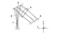
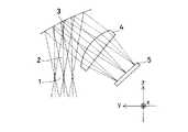
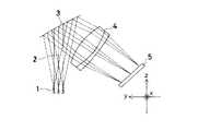
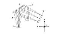
各実施例の構成パラメータは後記するが、以下の説明において、面番号は、観察者の瞳位置1から画像表示素子5へ向う逆追跡の面番号として示してある。そして、座標の取り方は、図1〜図6に示すように、観察者の瞳位置1中心から視軸方向をZ軸とし、紙面に垂直な方向に紙面表面から裏面に向かう方向を正としてX軸をとり、X軸、Z軸に垂直で右手系を構成するY軸を紙面内にとり、光軸は紙面のY−Z面内で折り曲げられるものとする。
【0023】
そして、後記する構成パラメータ中において、偏心量Y,Zと傾き角θが記載されている面については、基準軸(Z軸)あるいは基準面(1面)に対してのその面のY軸方向、Z軸方向の偏心量、及び、その面の中心軸のZ軸からの傾き角を意味し、その場合、θが正は反時計回りを意味する。なお、偏心量Y,Zと傾き角θの記載のない面は、その前の面と同軸であることを意味する。
【0024】
また、面間隔は、2面に関しては1面からのZ軸に沿う距離であり、同軸系部分(正のパワーを有する光学素子4)についてはその面から次の面までの軸上間隔である。なお、面間隔は、光軸に沿って逆追跡の方向を正として示してある。ただし、反射面以後では符号は反転する。
【0025】
また、各面において、アナモルフィック面の非球面形状は、その面を規定する座標上で、Ry、RxはそれぞれY−Z面(紙面)内の近軸曲率半径、X−Z面内での近軸曲率半径、Kx、KyはそれぞれX−Z面、Y−Z面内の円錐係数、AR、BRはそれぞれZ軸に対して回転対称な4次、6次の非球面係数、AP、BPはそれぞれZ軸に対して回転非対称な4次、6次の非球面係数とすると、非球面式は以下に示す通りである。
【0026】
さて、以下に示す実施例は全て右眼用の画像表示装置であり、左眼用は構成す光学要素を全てX−Z面に対称に配備することで実現できる。
また、実際の装置においては、接眼光学系によって光軸が屈曲する方向は、観察者の上方あるいは下方、側方何れの方向にあってもよいことは言うまでもない。
【0027】
図1〜図6に、それぞれ実施例1〜6の画像表示装置の光学系の単眼部分の断面図を示す。それぞれの断面図において、1は観察者の瞳位置、2は光軸、3は凹面鏡、4は正のパワーを有する光学素子、5は画像表示素子である。
【0028】
各実施例において、凹面鏡3は、実施例1、2、4はアナモルフィック面の表面鏡、実施例3、5、6はアナモルフィック面の裏面鏡からなり、正のパワーを有する光学素子4は、実施例1は両凸球面単レンズ、実施例2は画像表示素子5側に凹面を向けた正メニスカス球面単レンズ、実施例3は両面がアナモルフィック面からなる単レンズ、実施例4は両凸レンズと負メニスカスレンズの球面接合レンズ、実施例5は両凸レンズと両凹レンズの球面接合レンズ、実施例6は1面がアナモルフィック面からなる単レンズ2枚の接合レンズからなる。
【0029】
画角及び瞳直径については、
実施例1は、水平画角30°、垂直画角22.7°、瞳直径4mm、
実施例2は、水平画角30°、垂直画角22.7°、瞳直径16mm、
実施例3は、水平画角30°、垂直画角22.7°、瞳直径4mm、
実施例4は、水平画角30°、垂直画角22.7°、瞳直径8mm、
実施例5は、水平画角30°、垂直画角22.7°、瞳直径8mm、
実施例6は、水平画角35°、垂直画角26.6°、瞳直径8mmである。
【0030】
次に、上記実施例1〜6の構成パラメータを示す。
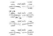
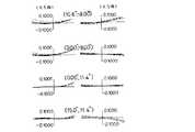
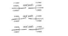
次に、上記実施例の中、実施例1、実施例5の横収差図をそれぞれ図7〜図9、図10〜図12に示す。これらの横収差図において、括弧内に示された数字は(水平画角,垂直画角)を表し、その画角における横収差を示す。
【0037】
なお、以上の何れの実施例においても、アイリリース、画像表示素子の大きさが異なる場合に、本発明は実施例の構成パラメーターを係数倍することで容易に実現できることは言うまでもない。
【0038】
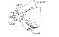
本発明の画像表示装置の様々な応用例が考えられるが、本発明の画像表示装置本体6に、例えば図13に示すような頭部への装着具7を取り付けることによって、頭部装着式の画像表示装置として用いることができる。
【0039】
以上の本発明の画像表示装置は、例えば次のように構成することができる。
〔1〕 画像を表示する画像表示素子と、前記画像表示素子によって形成された画像を中間像を作ることなく投影し、観察者の眼球に導く光学系とからなる画像表示装置において、前記光学系が、観察者の眼球側に凹面を向け、光軸に対して偏心した回転非対称な形状の反射面を有する少なくとも1枚の凹面鏡と、前記凹面鏡と前記画像表示素子との間に配置された正のパワーを有する少なくとも1個の光学素子とからなることを特徴とする画像表示装置。
【0040】
〔2〕 前記の正のパワーを有する光学素子の中の少なくとも1面が光軸に対して偏心していることを特徴とする上記〔1〕記載の画像表示装置。
【0041】
〔3〕 前記の正のパワーを有する光学素子の中の少なくとも1個が前記画像表示素子の側に凹面を向けた正メニスカスレンズであることを特徴とする上記〔1〕記載の画像表示装置。
【0042】
〔4〕 前記の正のパワーを有する光学素子が接合正レンズであることを特徴とする上記〔1〕記載の画像表示装置。
【0043】
〔5〕 前記凹面鏡が裏面鏡であることを特徴とする上記〔1〕から〔4〕の何れか1項記載の画像表示装置。
【0044】
〔6〕 前記光学系の焦点距離と前記の正のパワーを有する光学素子の焦点距離が以下の式を満たすことを特徴とする上記〔1〕から〔5〕の何れか1項記載の画像表示装置。
1<fy/fy0<5,又は,1<fx/fx0<5 ・・・(1)
ただし、fy,fxはそれぞれ前記の正のパワーを有する光学素子のY軸方向、X軸方向の焦点距離、fy0、fx0はそれぞれ前記光学系全体のY軸方向、X軸方向の焦点距離である。ここで、観察者の瞳に入射する光軸の方向をZ軸方向とし、凹面鏡の偏心がYZ平面で行われるようにY軸を定義し、Y軸とZ軸と直交するようにX軸を定義する。
【0045】
〔7〕 前記光学系の焦点距離と前記の正のパワーを有する光学素子の焦点距離が以下の式を満たすことを特徴とする上記〔1〕から〔5〕の何れか1項記載の画像表示装置。
【0046】
【発明の効果】
以上の説明から明らかなように、本発明の画像表示装置によると、中間像を作ることなく観察者の眼球に像を伝送する小型の光学系において、像面湾曲とその他の収差を同時に良好に補正して高解像な画像を観察し得る画像表示装置を提供することができる。
【図面の簡単な説明】
【図1】本発明の実施例1の画像表示装置の光路図である。
【図2】本発明の実施例2の画像表示装置の光路図である。
【図3】本発明の実施例3の画像表示装置の光路図である。
【図4】本発明の実施例4の画像表示装置の光路図である。
【図5】本発明の実施例5の画像表示装置の光路図である。
【図6】本発明の実施例6の画像表示装置の光路図である。
【図7】本発明の実施例1の横収差図の一部である。
【図8】本発明の実施例1の横収差図の別の部分である。
【図9】本発明の実施例1の横収差図の残りの部分である。
【図10】本発明の実施例5の横収差図の一部である。
【図11】本発明の実施例5の横収差図の別の部分である。
【図12】本発明の実施例5の横収差図の残りの部分である。
【図13】本発明による画像表示装置を頭部装着式画像表示装置として構成した場合の1例の概念図である。
【図14】従来の1つの画像表示装置の光学系を示す図である。
【図15】従来の別の画像表示装置の光学系を示す図である。
【符号の説明】
1…観察者の瞳位置
2…光軸
3…凹面鏡
4…正のパワーを有する光学素子
5…画像表示素子
6…画像表示装置本体
7…頭部への装着具[0001]
[Industrial application fields]
The present invention relates to an image display device, and more particularly to a head- or face-mounted image display device that can be held on an observer's head or face.
[0002]
[Prior art]
In the face-mounted image display device, it is desired that the weight is lighter and the size is smaller in order to reduce wearer fatigue. In particular, the length protruding from the face when worn on the face is desired to be as short as possible in order to improve the balance at the time of wearing. For this reason, a face-mounted visual display device using an optical system that transmits an image without creating an intermediate image has been proposed in the past, and a reduction in size and weight is achieved by eliminating the use of a relay optical system. .
[0003]
For example, US Pat. No. 4,026,641 has been proposed as an optical system for transmitting an image without forming such an intermediate image. In the present invention, as shown in FIG. 14, an image of an image display device such as a CRT is transmitted to an object surface by an image transmission element, and the image of the object surface is converted into a virtual image by a toric reflection surface decentered with respect to the optical axis. By displaying, a small and lightweight optical system can be provided.
[0004]
As another method, Japanese Patent Laid-Open No. 5-323229 has been proposed by the present applicant. The optical system of the present invention has a configuration as shown in FIG. 15, and transmits an image having a small curvature of field without forming an intermediate image by a concave mirror having a curvature that increases with distance from the optical axis. Yes.
[0005]
[Problems to be solved by the invention]
However, due to the curvature of field of the optical system of US Pat. No. 4,026,641, there is a problem that the projected virtual image becomes a curved surface and the periphery of the image is blurred during observation. In addition, the optical system disclosed in Japanese Patent Laid-Open No. 5-323229 has a small curvature of field, but other aberrations occur in the concave mirror. In recent years, high resolution of liquid crystal displays and the like has been advanced, and when a high resolution optical system corresponding to this is required, there is a possibility that the conventional method cannot be used.
[0006]
Japanese Patent Laid-Open No. 5-323229 also has a problem that the image plane does not become perpendicular to the optical axis because a decentered concave mirror is used in the optical system. When the image plane is not perpendicular to the optical axis, and an image display element with a small amount of emitted light in a direction other than the vertical direction, such as a liquid crystal display, is used, the image can be clearly seen due to insufficient light amount. It may not be possible.
[0007]
The present invention has been made in view of such problems of the prior art, and an object of the present invention is to provide an optical system capable of satisfactorily correcting field curvature and other aberrations simultaneously in an image display apparatus that does not produce an intermediate image. It is an object of the present invention to provide an image display apparatus that can sufficiently and clearly observe a high-resolution image.
[0008]
[Means for Solving the Problems]
In order to solve the above problems, an image display device according to the present invention projects an image display element for displaying an image and an image formed by the image display element without creating an intermediate image, and forms the image on an observer's eyeball. In an image display device comprising a guiding optical system,
The optical system is disposed between the concave mirror and the image display element, with at least one concave mirror having a rotationally asymmetric reflecting surface that is decentered with respect to the optical axis with the concave surface facing the eyeball side of the observer Comprising at least one optical element having a positive power and having a transmission surface arranged with a medium sandwiched on the concave side of the concave mirror,
At least one of the positive optical elements is decentered with respect to the optical axis;
The optical system is configured to satisfy the following conditional expression (1).
1 <fy / fy0 <5, or 1 <fx / fx0 <5 (1)
Where fy and fx are the focal lengths in the Y-axis direction and X-axis direction of the optical element having the positive power, respectively, and fy0 and fx0 are the focal points in the Y-axis direction and X-axis direction of the entire optical system, respectively. Distance. Here, the direction of the optical axis incident on the observer's pupil is the Z-axis direction, the Y-axis is defined so that the decentering of the concave mirror is performed in the YZ plane, and the X-axis is orthogonal to the Y-axis and the Z-axis. Define.
[0009]
In this case, at least one of the optical elements having positive power is decentered with respect to the optical axis, or at least one of the optical elements having positive power has a concave surface on the image display element side. The positive meniscus lens is preferably directed.
[0010]
[Action]
Below, the reason and effect | action which take the said structure in this invention are demonstrated. The following description will be made by back ray tracing for tracing light rays from the observer's pupil position toward the image display element for convenience in optical design. Further, it is assumed that the direction of the light beam emitted from the observer's pupil is the Z-axis direction, and the concave mirror is decentered in the YZ plane.
[0011]
In the present invention, the optical system of the image display device includes a concave mirror having a rotationally asymmetric reflecting surface that is decentered (tilted or shifted) sequentially from the observer's pupil along the optical axis, an optical element having positive power, and And an image display element. Since the power to form an image on the concave mirror and the optical element having positive power is divided, the curvature of the concave mirror can be reduced. Therefore, field curvature generated by the concave mirror can be reduced. At the same time, spherical aberration can be reduced by reducing the curvature of the concave mirror, and a good image can be observed. Furthermore, the angle between the image plane and the optical axis can be brought closer to the vertical due to the decrease in the curvature of the concave mirror.
[0012]
In addition, since the reflecting surface of the concave mirror has a rotationally asymmetric shape, it is possible to correct astigmatism caused by the difference in power between the direction in which the concave mirror is decentered and the direction in which it is not decentered. Aberration correction can be realized.
[0013]
In addition, in a face-mounted image display device, it is necessary to sufficiently secure a distance from the pupil position to the first surface, so-called eye release, so that glasses or the like can be worn. On the other hand, it is desirable that the length protruding from the face is as small as possible when it is attached to the face. Therefore, an optical element with positive power should be closer to the image display element than the concave mirror, so that the projection length from the face is smaller when the eye release is the same than when it is closer to the pupil than the concave mirror. Is possible and more preferable.
[0014]
Further, by shifting and decentering an optical element having a positive power, the amount of field curvature generated by this optical element changes, so that an appropriate shift is given to this optical element having a positive power. Thus, the inclination of the image plane with respect to the optical axis generated by the concave mirror can be corrected, and the image plane can be made more perpendicular to the optical axis.
[0015]
Further, by tilting the optical element having a positive power, the coma generated by the concave mirror can be easily corrected. Because it is possible to change the amount of coma generated by tilting an optical element having a positive power, and by giving an appropriate tilt to an optical element having a positive power, the coma generated by a concave mirror can be improved. It is because it can correct | amend to.
[0016]
Further, an optical element having a positive power must be arranged so as not to cast light from the pupil to the concave mirror. For this reason, an optical element having positive power must be at a certain distance from the concave mirror, which is a constraint in paraxial design. Therefore, as shown in FIG. 2 showing the optical system of Example 2 to be described later, when the positive meniscus lens 4 is used as an optical element having a positive power with the concave surface facing the
[0017]
Further, by using a cemented positive lens as an optical element having a positive power, it is possible to suppress lateral chromatic aberration that occurs in this optical element. Further, when a back mirror is used as the concave mirror, it is possible to correct chromatic aberration of magnification caused by the back mirror, and a high-resolution image can be observed sufficiently clearly.
[0018]
By the way, the back mirror has advantages such as rich durability, small change with time, and resistance to dust and dust compared to the front mirror. In addition, it is possible to change the surface shape without changing the focal length as a concave mirror, which is very advantageous in terms of aberration correction, and a high-resolution image can be obtained. Therefore, it is also desirable to use a back mirror as the concave mirror.
[0019]
If the focal length of the optical element having the above positive power and the focal length of the entire optical system satisfy the following formula, it is possible to reduce the power of the concave mirror and achieve a sufficient effect for aberration correction. In addition, the aberration generated by the power of the optical element can be sufficiently reduced.
1 <fy / fy0 <5, or 1 <fx / fx0 <5 (1)
Where fy and fx are the focal lengths of the optical element having positive power in the Y-axis direction and the X-axis direction, respectively, and fy0 and fx0 are the focal lengths of the entire optical system in the Y-axis direction and the X-axis direction, respectively. is there.
[0020]
If the relationship of the above formula (1) further satisfies the following formula (1) ′, the power of the concave mirror is reduced simultaneously in both the X-axis direction and the Y-axis direction, and the effect for correcting the aberration becomes remarkable. In addition, the aberration generated in the optical element can be made extremely small, which is particularly effective when a high-resolution image display element is used.
[0021]
【Example】
The configuration parameters of each embodiment will be described later. In the following description, the surface number is indicated as a surface number for reverse tracking from the observer's
[0023]
And, in the constituent parameters to be described later, with respect to the surface on which the eccentric amounts Y, Z and the inclination angle θ are described, the Y axis direction of the surface with respect to the reference axis (Z axis) or the reference surface (one surface) , The amount of eccentricity in the Z-axis direction, and the inclination angle of the central axis of the surface from the Z-axis, in which case θ positive means counterclockwise. In addition, the surface without the description of the eccentric amounts Y and Z and the inclination angle θ means that it is coaxial with the previous surface.
[0024]
The surface spacing is the distance along the Z-axis from one surface for the two surfaces, and the axial distance from that surface to the next surface for the coaxial part (optical element 4 having positive power). . The surface spacing is shown with the reverse tracking direction along the optical axis as positive. However, the sign is reversed after the reflecting surface.
[0025]
In each surface, the aspherical shape of the anamorphic surface is such that Ry and Rx are the paraxial radius of curvature in the YZ plane (paper surface) and the XZ plane on the coordinates defining the surface. The paraxial radius of curvature, Kx and Ky are the conical coefficients in the XZ plane and YZ plane, and AR and BR are rotationally symmetric 4th and 6th aspheric surfaces, respectively. Assuming that the coefficients, AP, and BP are rotationally asymmetric fourth-order and sixth-order aspheric coefficients, respectively, the aspheric expression is as follows.
[0026]
The embodiments shown below are all image display apparatuses for the right eye, and those for the left eye can be realized by arranging all the optical elements constituting the apparatus symmetrically on the XZ plane.
Further, in an actual apparatus, it goes without saying that the direction in which the optical axis is bent by the eyepiece optical system may be in any direction above, below, or lateral to the observer.
[0027]
1 to 6 are cross-sectional views of a monocular portion of the optical system of the image display apparatuses of Examples 1 to 6, respectively. In each cross-sectional view, 1 is an observer's pupil position, 2 is an optical axis, 3 is a concave mirror, 4 is an optical element having positive power, and 5 is an image display element.
[0028]
In each embodiment, the
[0029]
About angle of view and pupil diameter,
Example 1 has a horizontal field angle of 30 °, a vertical field angle of 22.7 °, a pupil diameter of 4 mm,
Example 2 has a horizontal field angle of 30 °, a vertical field angle of 22.7 °, a pupil diameter of 16 mm,
Example 3 has a horizontal field angle of 30 °, a vertical field angle of 22.7 °, a pupil diameter of 4 mm,
Example 4 has a horizontal field angle of 30 °, a vertical field angle of 22.7 °, a pupil diameter of 8 mm,
Example 5 has a horizontal field angle of 30 °, a vertical field angle of 22.7 °, a pupil diameter of 8 mm,
In Example 6, the horizontal field angle is 35 °, the vertical field angle is 26.6 °, and the pupil diameter is 8 mm.
[0030]
Next, the configuration parameters of Examples 1 to 6 are shown.
Next, among the above examples, lateral aberration diagrams of Example 1 and Example 5 are shown in FIGS. 7 to 9 and FIGS. 10 to 12, respectively. In these lateral aberration diagrams, the numbers shown in parentheses represent (horizontal field angle, vertical field angle), and represent lateral aberrations at that field angle.
[0037]
In any of the above embodiments, it goes without saying that the present invention can be easily realized by multiplying the constituent parameters of the embodiments by a factor when the sizes of the eye release and the image display element are different.
[0038]
Various application examples of the image display device of the present invention are conceivable. For example, by attaching a mounting
[0039]
The above-described image display device of the present invention can be configured as follows, for example.
[1] An image display device comprising: an image display element that displays an image; and an optical system that projects an image formed by the image display element without creating an intermediate image and guides the image to an observer's eyeball. Is a positive mirror disposed between the concave mirror and the image display element, and at least one concave mirror having a rotationally asymmetric reflecting surface that is decentered with respect to the optical axis, with the concave surface facing the eyeball side of the observer. An image display device comprising: at least one optical element having the following power:
[0040]
[2] The image display device according to [1], wherein at least one of the positive optical elements is decentered with respect to the optical axis.
[0041]
[3] The image display device according to [1], wherein at least one of the optical elements having positive power is a positive meniscus lens having a concave surface facing the image display element.
[0042]
[4] The image display device according to [1], wherein the optical element having positive power is a cemented positive lens.
[0043]
[5] The image display device according to any one of [1] to [4], wherein the concave mirror is a back mirror.
[0044]
[6] The image display according to any one of [1] to [5], wherein a focal length of the optical system and a focal length of the optical element having the positive power satisfy the following expression: apparatus.
1 <fy / fy0 <5, or 1 <fx / fx0 <5 (1)
However, fy and fx are the focal lengths in the Y-axis direction and X-axis direction of the optical element having the positive power, respectively, and fy0 and fx0 are the Y-axis direction and X-axis direction of the entire optical system, respectively. The focal length. Here, the direction of the optical axis incident on the observer's pupil is the Z-axis direction, the Y-axis is defined so that the decentering of the concave mirror is performed in the YZ plane, and the X-axis is orthogonal to the Y-axis and the Z-axis. Define.
[0045]
[7] The image display according to any one of [1] to [5], wherein a focal length of the optical system and a focal length of the optical element having the positive power satisfy the following expression: apparatus.
[0046]
【The invention's effect】
As is clear from the above description, according to the image display device of the present invention, in a small optical system that transmits an image to the eyeball of the observer without creating an intermediate image, the field curvature and other aberrations are improved at the same time. An image display apparatus that can correct and observe a high-resolution image can be provided.
[Brief description of the drawings]
FIG. 1 is an optical path diagram of an image display device according to a first embodiment of the present invention.
FIG. 2 is an optical path diagram of the image display apparatus according to the second embodiment of the present invention.
FIG. 3 is an optical path diagram of an image display device according to a third embodiment of the present invention.
FIG. 4 is an optical path diagram of an image display apparatus according to a fourth embodiment of the present invention.
FIG. 5 is an optical path diagram of an image display apparatus according to a fifth embodiment of the present invention.
FIG. 6 is an optical path diagram of the image display apparatus according to the sixth embodiment of the present invention.
FIG. 7 is a part of a lateral aberration diagram of Example 1 of the present invention.
FIG. 8 is another part of the lateral aberration diagram of Example 1 of the present invention.
FIG. 9 is the remaining part of the lateral aberration diagram of Example 1 of the present invention.
FIG. 10 is a part of a lateral aberration diagram of Example 5 of the present invention.
FIG. 11 is another part of the lateral aberration diagram of Example 5 of the present invention.
FIG. 12 is the remaining part of the lateral aberration diagram of Example 5 of the present invention.
FIG. 13 is a conceptual diagram of an example when the image display device according to the present invention is configured as a head-mounted image display device.
FIG. 14 is a diagram showing an optical system of one conventional image display apparatus.
FIG. 15 is a diagram showing an optical system of another conventional image display apparatus.
[Explanation of symbols]
DESCRIPTION OF
Claims (1)
Translated fromJapanese前記光学系が、観察者の眼球側に凹面を向け、光軸に対して偏心した回転非対称な形状の反射面を有する少なくとも1枚の凹面鏡と、前記凹面鏡と前記画像表示素子との間に配置された正のパワーを有する少なくとも1個の光学素子とからなり、前記凹面鏡の凹面側に媒質を挟んで配置された透過面を有し、
前記正のパワーを有する光学素子の中の少なくとも1面が、光軸に対して偏心しており、
前記光学系が、以下条件式(1)を満足するように構成されていることを特徴とする画像表示装置。
1<fy/fy0<5,又は,1<fx/fx0<5 ・・・(1)
ただし、fy,fxはそれぞれ前記正のパワーを有する光学素子のY軸方向、X軸方向の焦点距離、fy0、fx0はそれぞれ前記光学系全体のY軸方向、X軸方向の焦点距離である。ここで、観察者の瞳に入射する光軸の方向をZ軸方向とし、凹面鏡の偏心がYZ平面で行われるようにY軸を定義し、Y軸とZ軸と直交するようにX軸を定義する。In an image display device comprising an image display element that displays an image, and an optical system that projects an image formed by the image display element without creating an intermediate image and guides it to an eyeball of an observer.
The optical system is disposed between the concave mirror and the image display element, with at least one concave mirror having a rotationally asymmetric reflecting surface that is decentered with respect to the optical axis with the concave surface facing the eyeball side of the observer Comprising at least one optical element having a positive power, and having a transmission surface arranged with a medium sandwiched on the concave side of the concave mirror,
At least one of the positive optical elements is decentered with respect to the optical axis;
It said optical system, the following conditional expressions (1)images displayyou characterized in that it is configured to satisfy.
1 <fy / fy0 <5, or 1 <fx / fx0 <5 (1)
Where fy and fx are the focal lengths in the Y-axis direction and X-axis direction of the optical element having the positive power, respectively, and fy0 and fx0 are the focal points in the Y-axis direction and X-axis direction of the entire optical system, respectively. Distance. Here, the direction of the optical axis incident on the observer's pupil is the Z-axis direction, the Y-axis is defined so that the decentering of the concave mirror is performed in the YZ plane, and the X-axis is orthogonal to the Y-axis and the Z-axis. Define.
Priority Applications (2)
| Application Number | Priority Date | Filing Date | Title |
|---|---|---|---|
| JP30898094AJP3672951B2 (en) | 1994-12-13 | 1994-12-13 | Image display device |
| US08/570,861US5726807A (en) | 1994-12-13 | 1995-12-12 | Small light weight head-mounted or face-mounted image display apparatus |
Applications Claiming Priority (1)
| Application Number | Priority Date | Filing Date | Title |
|---|---|---|---|
| JP30898094AJP3672951B2 (en) | 1994-12-13 | 1994-12-13 | Image display device |
Publications (2)
| Publication Number | Publication Date |
|---|---|
| JPH08166541A JPH08166541A (en) | 1996-06-25 |
| JP3672951B2true JP3672951B2 (en) | 2005-07-20 |
Family
ID=17987519
Family Applications (1)
| Application Number | Title | Priority Date | Filing Date |
|---|---|---|---|
| JP30898094AExpired - Fee RelatedJP3672951B2 (en) | 1994-12-13 | 1994-12-13 | Image display device |
Country Status (2)
| Country | Link |
|---|---|
| US (1) | US5726807A (en) |
| JP (1) | JP3672951B2 (en) |
Families Citing this family (65)
| Publication number | Priority date | Publication date | Assignee | Title |
|---|---|---|---|---|
| JP3496890B2 (en) | 1993-10-05 | 2004-02-16 | キヤノン株式会社 | Display device |
| US6166866A (en)* | 1995-02-28 | 2000-12-26 | Canon Kabushiki Kaisha | Reflecting type optical system |
| EP0730180B1 (en) | 1995-02-28 | 2002-09-04 | Canon Kabushiki Kaisha | Reflecting type of zoom lens |
| US6021004A (en) | 1995-02-28 | 2000-02-01 | Canon Kabushiki Kaisha | Reflecting type of zoom lens |
| JPH09211331A (en)* | 1996-01-29 | 1997-08-15 | Canon Inc | Reflective optical system |
| JPH09219832A (en)* | 1996-02-13 | 1997-08-19 | Olympus Optical Co Ltd | Image display |
| JP3761957B2 (en) | 1996-02-15 | 2006-03-29 | キヤノン株式会社 | Reflective optical system and imaging apparatus using the same |
| JPH10123454A (en)* | 1996-10-16 | 1998-05-15 | Olympus Optical Co Ltd | Head mounted picture display device |
| JPH10161018A (en)* | 1996-11-27 | 1998-06-19 | Olympus Optical Co Ltd | Optical system |
| US6128144A (en) | 1996-12-02 | 2000-10-03 | Olympus Optical Co., Ltd. | Optical system for camera and camera apparatus |
| JP3929153B2 (en)* | 1998-01-07 | 2007-06-13 | オリンパス株式会社 | Imaging optics |
| US6022114A (en)* | 1998-05-01 | 2000-02-08 | Nikon Corporation | Anamorphic afocal beam shaping assembly |
| JP2000098293A (en) | 1998-06-19 | 2000-04-07 | Canon Inc | Image observation device |
| US6201647B1 (en)* | 1998-07-06 | 2001-03-13 | Minolta Co., Ltd. | Image display apparatus |
| JP2000206446A (en)* | 1999-01-11 | 2000-07-28 | Olympus Optical Co Ltd | Image display device |
| JP2000221440A (en)* | 1999-01-29 | 2000-08-11 | Olympus Optical Co Ltd | Picture display device |
| JP4174126B2 (en)* | 1999-03-17 | 2008-10-29 | 株式会社トプコン | Ophthalmic measuring device |
| JP2003279883A (en)* | 2002-03-21 | 2003-10-02 | 良彰 ▲秦▼ | Cap with display device |
| JP4287375B2 (en)* | 2002-09-24 | 2009-07-01 | 健爾 西 | Image display apparatus and projection optical system |
| US7206133B2 (en)* | 2003-05-22 | 2007-04-17 | Optical Research Associates | Light distribution apparatus and methods for illuminating optical systems |
| WO2004106983A2 (en)* | 2003-05-22 | 2004-12-09 | Optical Research Associates | Illumination in optical systems |
| WO2004106982A2 (en)* | 2003-05-22 | 2004-12-09 | Optical Research Associates | Optical combiner designs and head mounted displays |
| TW200502582A (en)* | 2003-07-09 | 2005-01-16 | Leadtek Research Inc | Head-mounted display and optical engine of the same |
| US7450310B2 (en)* | 2005-05-03 | 2008-11-11 | Optical Research Associates | Head mounted display devices |
| EP1792225A4 (en) | 2004-09-01 | 2010-07-28 | Optical Res Associates | Compact head mounted display devices with tilted/decentered lens element |
| DE102007036974B4 (en) | 2007-08-06 | 2019-10-10 | Carl Zeiss Ag | HMD device |
| US9182596B2 (en) | 2010-02-28 | 2015-11-10 | Microsoft Technology Licensing, Llc | See-through near-eye display glasses with the optical assembly including absorptive polarizers or anti-reflective coatings to reduce stray light |
| US20150309316A1 (en) | 2011-04-06 | 2015-10-29 | Microsoft Technology Licensing, Llc | Ar glasses with predictive control of external device based on event input |
| US9223134B2 (en) | 2010-02-28 | 2015-12-29 | Microsoft Technology Licensing, Llc | Optical imperfections in a light transmissive illumination system for see-through near-eye display glasses |
| US9341843B2 (en) | 2010-02-28 | 2016-05-17 | Microsoft Technology Licensing, Llc | See-through near-eye display glasses with a small scale image source |
| US9759917B2 (en) | 2010-02-28 | 2017-09-12 | Microsoft Technology Licensing, Llc | AR glasses with event and sensor triggered AR eyepiece interface to external devices |
| US9129295B2 (en) | 2010-02-28 | 2015-09-08 | Microsoft Technology Licensing, Llc | See-through near-eye display glasses with a fast response photochromic film system for quick transition from dark to clear |
| US9285589B2 (en) | 2010-02-28 | 2016-03-15 | Microsoft Technology Licensing, Llc | AR glasses with event and sensor triggered control of AR eyepiece applications |
| US9097890B2 (en) | 2010-02-28 | 2015-08-04 | Microsoft Technology Licensing, Llc | Grating in a light transmissive illumination system for see-through near-eye display glasses |
| US20120249797A1 (en) | 2010-02-28 | 2012-10-04 | Osterhout Group, Inc. | Head-worn adaptive display |
| US9097891B2 (en) | 2010-02-28 | 2015-08-04 | Microsoft Technology Licensing, Llc | See-through near-eye display glasses including an auto-brightness control for the display brightness based on the brightness in the environment |
| US9134534B2 (en) | 2010-02-28 | 2015-09-15 | Microsoft Technology Licensing, Llc | See-through near-eye display glasses including a modular image source |
| US8477425B2 (en) | 2010-02-28 | 2013-07-02 | Osterhout Group, Inc. | See-through near-eye display glasses including a partially reflective, partially transmitting optical element |
| US10180572B2 (en) | 2010-02-28 | 2019-01-15 | Microsoft Technology Licensing, Llc | AR glasses with event and user action control of external applications |
| US8488246B2 (en) | 2010-02-28 | 2013-07-16 | Osterhout Group, Inc. | See-through near-eye display glasses including a curved polarizing film in the image source, a partially reflective, partially transmitting optical element and an optically flat film |
| US9229227B2 (en) | 2010-02-28 | 2016-01-05 | Microsoft Technology Licensing, Llc | See-through near-eye display glasses with a light transmissive wedge shaped illumination system |
| US8482859B2 (en) | 2010-02-28 | 2013-07-09 | Osterhout Group, Inc. | See-through near-eye display glasses wherein image light is transmitted to and reflected from an optically flat film |
| US8467133B2 (en) | 2010-02-28 | 2013-06-18 | Osterhout Group, Inc. | See-through display with an optical assembly including a wedge-shaped illumination system |
| US9091851B2 (en) | 2010-02-28 | 2015-07-28 | Microsoft Technology Licensing, Llc | Light control in head mounted displays |
| US9128281B2 (en) | 2010-09-14 | 2015-09-08 | Microsoft Technology Licensing, Llc | Eyepiece with uniformly illuminated reflective display |
| US9366862B2 (en) | 2010-02-28 | 2016-06-14 | Microsoft Technology Licensing, Llc | System and method for delivering content to a group of see-through near eye display eyepieces |
| US8472120B2 (en) | 2010-02-28 | 2013-06-25 | Osterhout Group, Inc. | See-through near-eye display glasses with a small scale image source |
| WO2011106797A1 (en)* | 2010-02-28 | 2011-09-01 | Osterhout Group, Inc. | Projection triggering through an external marker in an augmented reality eyepiece |
| JP5574226B2 (en)* | 2010-03-23 | 2014-08-20 | 株式会社ニコン | Interference objective lens and microscope apparatus having the same |
| US8625200B2 (en)* | 2010-10-21 | 2014-01-07 | Lockheed Martin Corporation | Head-mounted display apparatus employing one or more reflective optical surfaces |
| US8736967B1 (en) | 2010-11-19 | 2014-05-27 | SA Photonics, Inc. | Anamorphic eyepiece |
| US9618746B2 (en) | 2010-11-19 | 2017-04-11 | SA Photonics, Inc. | High resolution wide field of view digital night vision system |
| EP2699006A1 (en)* | 2012-08-16 | 2014-02-19 | ESSILOR INTERNATIONAL (Compagnie Générale d'Optique) | Pictures positioning on display elements |
| DE102014207499B4 (en)* | 2014-04-17 | 2017-02-09 | Carl Zeiss Jena Gmbh | Spectacle lens for a display device that can be placed on the head of a user and forms an image |
| US10564424B2 (en) | 2014-08-18 | 2020-02-18 | Sony Corporation | Image display device and display apparatus |
| KR102295452B1 (en) | 2014-10-24 | 2021-08-27 | 이매진 코퍼레이션 | Microdisplay based immersive headset |
| US9651786B1 (en) | 2015-05-05 | 2017-05-16 | SA Photonics, Inc. | Systems and methods for augmented reality devices with light security |
| CN105717643A (en)* | 2016-04-13 | 2016-06-29 | 中山联合光电科技股份有限公司 | A reflective virtual reality optical system |
| US11378801B1 (en) | 2017-05-25 | 2022-07-05 | Vision Products, Llc | Wide field of view night vision system |
| JP7183610B2 (en)* | 2018-07-30 | 2022-12-06 | セイコーエプソン株式会社 | virtual image display |
| US10969675B1 (en) | 2019-06-10 | 2021-04-06 | Facebook Technologies, Llc | Optical assemblies having scanning reflectors for projecting augmented reality content |
| US11048087B2 (en)* | 2019-06-10 | 2021-06-29 | Facebook Technologies, Llc | Optical assemblies having polarization volume gratings for projecting augmented reality content |
| US11181815B1 (en) | 2019-06-11 | 2021-11-23 | Facebook Technologies, Llc | Optical devices including reflective spatial light modulators for projecting augmented reality content |
| US11204649B2 (en) | 2020-01-30 | 2021-12-21 | SA Photonics, Inc. | Head-mounted display with user-operated control |
| JP2022189083A (en)* | 2021-06-10 | 2022-12-22 | 株式会社エビデント | Observation device, reflector, and method for observing phase object |
Family Cites Families (23)
| Publication number | Priority date | Publication date | Assignee | Title |
|---|---|---|---|---|
| US4026641A (en)* | 1975-12-30 | 1977-05-31 | The United States Of America As Represented By The Secretary Of The Army | Toric reflector display |
| JPS5930522B2 (en)* | 1979-04-06 | 1984-07-27 | 株式会社共立 | Portable power chain saw |
| JPS55153901A (en)* | 1979-05-18 | 1980-12-01 | Hitachi Ltd | Reverse side mirror |
| US4669810A (en)* | 1984-02-03 | 1987-06-02 | Flight Dynamics, Inc. | Head up display system |
| JPS62214782A (en)* | 1986-03-17 | 1987-09-21 | Toshiba Corp | Display device |
| FR2732479B1 (en)* | 1987-02-27 | 1997-08-08 | Thomson Csf | HIGH HEAD VISUALIZATION DEVICE, HOLOGRAPHIC TYPE WITH SIMPLIFIED RELAY OPTICS |
| US4854688A (en)* | 1988-04-14 | 1989-08-08 | Honeywell Inc. | Optical arrangement |
| GB8916206D0 (en)* | 1989-07-14 | 1989-11-08 | Marconi Gec Ltd | Helmet systems |
| JPH05134208A (en)* | 1991-11-12 | 1993-05-28 | Olympus Optical Co Ltd | Image observation device |
| JP3155336B2 (en)* | 1992-04-24 | 2001-04-09 | オリンパス光学工業株式会社 | Visual display device |
| JP3155337B2 (en)* | 1992-04-24 | 2001-04-09 | オリンパス光学工業株式会社 | Visual display device |
| JP3155341B2 (en)* | 1992-05-26 | 2001-04-09 | オリンパス光学工業株式会社 | Visual display device |
| GB9214909D0 (en)* | 1992-07-14 | 1992-08-26 | Secr Defence | Helmet-mounted optical systems |
| JP3155360B2 (en)* | 1992-07-27 | 2001-04-09 | オリンパス光学工業株式会社 | Visual display device |
| JPH06194598A (en)* | 1992-12-25 | 1994-07-15 | Olympus Optical Co Ltd | Display device of head mounting type |
| JP3212203B2 (en)* | 1993-02-09 | 2001-09-25 | オリンパス光学工業株式会社 | Visual display device |
| US5546227A (en)* | 1993-02-24 | 1996-08-13 | Olympus Optical Co., Ltd. | Image display apparatus |
| JP3245472B2 (en)* | 1993-02-24 | 2002-01-15 | オリンパス光学工業株式会社 | Head mounted display |
| US5539578A (en)* | 1993-03-02 | 1996-07-23 | Olympus Optical Co., Ltd. | Image display apparatus |
| US5384654A (en)* | 1993-05-10 | 1995-01-24 | Olympus Optical Co., Ltd. | Image observation device |
| JPH06324285A (en)* | 1993-05-13 | 1994-11-25 | Olympus Optical Co Ltd | Visual display device |
| JP3397832B2 (en)* | 1993-05-13 | 2003-04-21 | オリンパス光学工業株式会社 | Head mounted video display |
| JP3382683B2 (en)* | 1993-10-22 | 2003-03-04 | オリンパス光学工業株式会社 | Concentric optical system |
- 1994
- 1994-12-13JPJP30898094Apatent/JP3672951B2/ennot_activeExpired - Fee Related
- 1995
- 1995-12-12USUS08/570,861patent/US5726807A/ennot_activeExpired - Lifetime
Also Published As
| Publication number | Publication date |
|---|---|
| US5726807A (en) | 1998-03-10 |
| JPH08166541A (en) | 1996-06-25 |
Similar Documents
| Publication | Publication Date | Title |
|---|---|---|
| JP3672951B2 (en) | Image display device | |
| JP3683317B2 (en) | Image display device | |
| US5812323A (en) | Image display apparatus | |
| JP3854763B2 (en) | Image display device | |
| US6317267B1 (en) | Head or face mounted image display apparatus | |
| US6008778A (en) | Visual display apparatus | |
| JP3645618B2 (en) | Image display device | |
| JP3392929B2 (en) | Video display device | |
| EP0790516A1 (en) | Image display apparatus | |
| JPH08146341A (en) | Image display device | |
| JPH07191274A (en) | Image display device | |
| JP3155335B2 (en) | Visual display device | |
| JP3155337B2 (en) | Visual display device | |
| JP3497594B2 (en) | Image display device | |
| JP7330796B2 (en) | Optical system and display device using the same | |
| JPH07134266A (en) | Visual sense display device | |
| JPH05323229A (en) | Visual display device | |
| JP3542213B2 (en) | Image display device | |
| JP3542214B2 (en) | Image display device | |
| JPH0973043A (en) | Video display device | |
| JP3683338B2 (en) | Head-mounted image display device | |
| JP3597456B2 (en) | Eccentric optical system and visual display device using the same | |
| JP3607736B2 (en) | Image display device | |
| JPH07218859A (en) | Image display device | |
| JP2004185023A (en) | Image display device |
Legal Events
| Date | Code | Title | Description |
|---|---|---|---|
| A521 | Request for written amendment filed | Free format text:JAPANESE INTERMEDIATE CODE: A523 Effective date:20031215 | |
| A02 | Decision of refusal | Free format text:JAPANESE INTERMEDIATE CODE: A02 Effective date:20040128 | |
| A521 | Request for written amendment filed | Free format text:JAPANESE INTERMEDIATE CODE: A523 Effective date:20040302 | |
| A911 | Transfer to examiner for re-examination before appeal (zenchi) | Free format text:JAPANESE INTERMEDIATE CODE: A911 Effective date:20040524 | |
| TRDD | Decision of grant or rejection written | ||
| A01 | Written decision to grant a patent or to grant a registration (utility model) | Free format text:JAPANESE INTERMEDIATE CODE: A01 Effective date:20050413 | |
| A61 | First payment of annual fees (during grant procedure) | Free format text:JAPANESE INTERMEDIATE CODE: A61 Effective date:20050421 | |
| FPAY | Renewal fee payment (event date is renewal date of database) | Free format text:PAYMENT UNTIL: 20090428 Year of fee payment:4 | |
| FPAY | Renewal fee payment (event date is renewal date of database) | Free format text:PAYMENT UNTIL: 20090428 Year of fee payment:4 | |
| FPAY | Renewal fee payment (event date is renewal date of database) | Free format text:PAYMENT UNTIL: 20100428 Year of fee payment:5 | |
| FPAY | Renewal fee payment (event date is renewal date of database) | Free format text:PAYMENT UNTIL: 20110428 Year of fee payment:6 | |
| LAPS | Cancellation because of no payment of annual fees |