JP3669057B2 - Transport system to stocker - Google Patents
Transport system to stockerDownload PDFInfo
- Publication number
- JP3669057B2 JP3669057B2JP16369896AJP16369896AJP3669057B2JP 3669057 B2JP3669057 B2JP 3669057B2JP 16369896 AJP16369896 AJP 16369896AJP 16369896 AJP16369896 AJP 16369896AJP 3669057 B2JP3669057 B2JP 3669057B2
- Authority
- JP
- Japan
- Prior art keywords
- stocker
- container
- cassette
- transport
- ceiling
- Prior art date
- Legal status (The legal status is an assumption and is not a legal conclusion. Google has not performed a legal analysis and makes no representation as to the accuracy of the status listed.)
- Expired - Fee Related
Links
Images


Landscapes
- Warehouses Or Storage Devices (AREA)
- Sheets, Magazines, And Separation Thereof (AREA)
- Container, Conveyance, Adherence, Positioning, Of Wafer (AREA)
Description
Translated fromJapanese【0001】
【発明の属する技術分野】
本発明は、複数のストッカと、この複数のストッカを順次経由するよう走行自在に設けられ、前記ストッカの各々に対してウェーハを収納するカセット又はコンテナの受渡しを行う天井搬送装置とを有する搬送システムに関し、特に天井搬送装置の搬送効率を向上させるものに関する。
【0002】
【従来の技術】
例えば半導体製造用クリーンルームにおいては、ベイと呼ばれる工程の各々に種々の製造装置が配設され、各製造装置で特有のウェーハ処理が行われる。普通、各製造装置の処理速度が異なるため、工程毎にバッファ機能と保管機能を兼ね備えたストッカが設けられる。
【0003】
そして、ストッカからストッカへの各工程間の搬送は、複数のストッカを順次経由するよう走行自在に設けられ、前記ストッカの各々に対してウェーハの収納を行うカセット又はコンテナの受渡しを行う天井搬送装置により行われる搬送システムになっている。
【0004】
このような搬送システムの従来例を図4により説明する。図において、搬送システムは、複数のストッカ101と、この複数のストッカ101を順次経由して走行自在な天井搬送装置102とを有して構成される。
【0005】
ストッカ101は、ストッカ内搬送手段104の走行経路の両側に、荷(ウェーハを収納するカセット)103の多数を上下左右に規則正しく並べて保管する第1保管棚105と第2保管棚106とを配設してなる。そして、第2保管棚106の上隅が切り取られており、この切取り部分に荷の受渡しを行うための棚部107が設けられている。また、第2保管棚106の適所に工程内の製造装置に対する荷103の出入庫口108が設けられている。
ストッカ内搬送手段104は、棚部107に対する荷103の移載、第1保管棚105と第2保管棚106の所定箇所に対する移載、および、出入庫口108に対する荷103の移載に対応できるようになっている。
一方、天井搬送装置102は、レール110に沿って走行自在な台車111にチャック112を昇降自在につり下げたものである。
【0006】
上述した搬送システムにおいては、天井搬送装置102で運んできた荷103をストッカ101に収納したり、工程内の製造装置に出庫する場合の作動は以下の通りである。
まず、天井搬送装置102の台車111が図示のように、所定のストッカ101の棚部107の上で停止する。そして、チャック112を下げて、棚部107の上に荷103を載せて渡す。
つぎに、ストッカ内搬送手段104が棚部107から荷103を受け取り、第1保管棚105又は第2保管棚106のいずれかの空いた場所に収納するか、これら保管棚105,106に収納せずに直接出入庫口108まで移載する。
【0007】
【発明を解決しようとする課題】
しかしながら前述した従来の搬送システムにおいては、複数のストッカ101の各々が一か所の棚部107を有する構成になっているため、天井搬送装置102から特定のストッカ101に荷103を卸す際に、天井搬送装置102が特定のストッカ101へ荷103を運んできても、たまたまそのストッカ101の棚部107に荷103が載ったままであったり、ストッカ内搬送手段104が棚部107に載った荷103に対して移載作業中であると、天井搬送装置102から荷103を卸すことができず、天井搬送装置102の台車111の待ち時間が発生する。そのため、天井搬送装置102からストッカ101への荷103の移載に時間がかかるという問題点があった。また、天井搬送装置102の台車111が停止している間は、他の台車111の搬送経路を閉鎖することになり、搬送システムの搬送効率が下がる原因になっているという問題点もあった。
【0008】
そこで本発明は、天井搬送車から複数のストッカへの荷の移載時間を短縮するとともに、搬送効率を向上させるストッカへの搬送システムを提供することを目的としたものである。
【0009】
【課題を解決するための手段】
前述した目的を達成するために、本発明のうちで請求項1の発明は、
複数のストッカと、
この複数のストッカを順次経由するよう走行自在に設けられるとともに、昇降自在につり下げられたチャック手段を有し、前記ストッカの各々に対してウエハを収納するカセット又はコンテナの受渡しを行う天井搬送装置と、
を有する搬送システムであって、
前記ストッカは、前記カセット又はコンテナの多数を保管する保管棚と、前記天井搬送装置と前記カセット又はコンテナの受渡しを行うための棚部と、前記棚部と前記保管棚との間で前記カセット又はコンテナの搬送を行うために前記保管棚に沿って走行自在で、前記天井搬送装置の走行方向と平行に走行するストッカ内搬送手段とを備えてなり、
前記棚部は、前記天井搬送装置の走行方向に沿って列設された2以上のカセット又はコンテナの受渡し部を有し、
前記天井搬送装置は、2以上のカセット又はコンテナの受渡し部のうち空いている受渡し部に対してカセット又はコンテナの受渡しができるように、選択的なカセット又はコンテナの受渡しが可能であり、
前記ストッカ内搬送装置は、2以上のカセット又はコンテナの受渡し部のいずれかに対して選択的な搬送が可能になっているものである。
これにより、特定の受渡し部にカセット又はコンテナがある状態の場合や特定の受渡し部に対するストッカ内搬送手段の搬送が行われている場合には、天井搬送装置は走行方向の停止位置を変えて、空いている受渡し部に対してカセット又はコンテナの移載を行うことができる。
また、ストッカ内搬送手段は、走行方向の停止位置を変えるだけで、2以上の荷の受渡し部のいずれに対しても移載可能になる。更に、ストッカをクリーンルーム内に設置する場合でも、天井搬送装置の搬送効率を上げて、限られた空間を有効に活用できる。
【0010】
削除
【0011】
また請求項2の発明は、請求項1において、前記天井搬送装置の選択的な前記カセット又はコンテナの受渡しと、前記ストッカ内搬送手段の選択的なカセット又はコンテナの搬送は、特定のカセット又はコンテナの受渡し位置を認識できる制御装置により行われるものである。
これにより、複数のストッカの棚部の空き状況、各ストッカの棚部のどの受け若し部にカセット又はコンテナがあるかの情報処理は、複数のストッカと天井搬送装置を統括するメインコンピュータ等の制御装置が所定のソフトウェアに基づいて行われており、特定のカセット又はコンテナの受渡し位置を認識して、カセット又はコンテナの混同が生じないようになっている。
【0012】
削除
【0013】
【発明の実施の形態】
本発明の実施の形態を、図示例とともに説明する。
図1は、本発明システムを構成する機器の要部の斜視図であり、図2は、荷の具体的形態を示す斜視図であり、図3は、本発明システムの機器構成を示すレイアウト図である。
【0014】
図1において、本発明の一実施形態を示す搬送システムは、半導体製造用クリーンルームの各工程毎に設置された複数のストッカ1のうちの一つを例示して説明される。
【0015】
すなわち、搬送システムは、複数のストッカ1と、この複数のストッカ1を順次経由して走行自在な天井搬送装置2とを主たる機器として構成される。
【0016】
天井搬送装置2は、レール31に沿って一台以上の台車32を走行自在とするものであり、台車32の各々には昇降自在につり下げられたチャック手段33が設けられている。
【0017】
チャック手段33が荷(ウェーハを収納するカセット)3を把持して、台車32の上限位置まで上昇させた状態で、台車32が走行する。台車32がレール31に沿って走行し所定位置で停止すると、台車32から荷3を把持するチャック手段33を下降させ、チャック33を解放すると荷3が渡される。また空のチャック手段33をつり下げた台車32がレール31に沿って走行し所定位置で停止すると、台車32から解放状態のチャック手段33を下降させ、荷3を把持すると、荷3を受け取ることができる。このように、天井搬送装置2は荷3の所定位置における受渡しが可能に構成されている。
【0018】
ストッカ1は循環するレール3に沿って複数台が順番に配設されるが、図示例では一台のストッカ1のみが図示されている。このストッカ1は、ストッカ内搬送手段11の走行経路の両側に、荷3の多数を上下左右に規則正しく並べて保管する第1保管棚12と第2保管棚13とを配設してなる。そして、第1保管棚12に対面する第2保管棚13の最上段の一列全部が省かれており、第2保管棚13の上板の全体が棚部14になっている。この棚部14は、図示例ではナンバー○1から○7までの7つの受渡し部15に区分されている。この区分はフラットな棚部14を区分しているだけであり、受渡し部15の数の設定は任意にできる。例えばナンバー○1から○5迄を第2保管棚13の一部として使用し、ナンバー○6と○7の二つを受渡し部15として使用することができる。このような使い分けは後述するメインコンピュータに対する入力で設定可能である。
【0019】
また、棚部14は天井搬送装置2の台車32のレール31の走行方向と平行に設けられており、更に台車32のチャック手段33の真下に棚部14が位置するようになっている。これにより、台車32が棚部14のナンバー○1〜○7のいずれかの上で停止するだけで、棚部14のいずれかの受渡し部15に対する選択的な荷3の前述した受渡しが可能になっている。なお、16は、第2保管棚13の適所に設けられ、工程内の製造装置に対する荷3の出入庫を可能とする出入庫口である。
【0020】
ストッカ内搬送手段11は、棚部14の所定の受渡し部15に対する荷3の移載、第1保管棚12と第2保管棚13の所定箇所に対する荷3の移載、および、第2保管棚13の適所に設けられた出入庫口16に対する荷3の移載に対応できるようになっている。そのため、ストッカ内搬送手段11は、第1保管棚12と第2保管棚13の間の軌道台21と、この軌道台21に沿って走行自在な走行体22と、走行体22に沿って上下方向に移動自在、且つ、第1保管棚12または第2保管棚13に向かって旋回自在、必要に応じて、第1保管棚12または第2保管棚13に向かって進退自在に前記走行体22に設けられたチャック手段23とを備えてなる。
また、天井搬送装置3のレール31とストッカ内搬送手段11の軌道台21とは平行になっている。したがって、走行体22が軌道台21に沿って停止する位置を変えるだけで、ナンバー○1から○7までの7つの受渡し部15のいずれかに対して選択的な荷3の移載が可能になる。
【0021】
つぎに、上述した搬送システムにおける作動を、特に天井搬送装置2からストッカ1への荷3を渡す場合について説明する。
まず、荷3を運んできた天井搬送装置2の台車32は、棚部14の受渡し部15のうちの空いている場所を認識してその上に停止する。図示例ではナンバー○4と○7の受渡し部15が空いており、番号の若いナンバー○4の上に台車32が停止している状態を示す。
つぎに、台車32から荷3を把持するチャック手段33を下げて、受渡し部15の上に荷3が載ると、チャック手段33を解放して荷3の移載を完了する。移載の完了後、チャック手段33を上昇させて、台車32は次の荷3の受渡しに向けて走行を開始する。
この天井搬送装置2による荷3の受渡しが行われている受渡し部15以外の受渡し部15に対して、ストッカ内搬送手段11が軌道台21に沿って走行する。そして、所定の受渡し部15の前でストッカ内搬送装置11が停止して荷3を受け取り、ストッカ内搬送装置11が走行しチャック手段23を所定位置にして第1保管棚12又は第2保管棚13のいずれかの空いた場所に荷3を収納するか、これら保管棚12,13に収納せずに直接出入庫口16まで荷3を移載することが行われる。
【0022】
したがって、ストッカ内搬送手段11がナンバー○2の受渡し部15で荷3の移載を行っている場合でも、天井搬送装置2はナンバー○4や○7の如く空いている受渡し部15に対して荷3の受渡しができるので、ストッカ1と天井搬送装置2の荷3の受渡しが自由になり、ストッカー1側のビジー(受渡し部15に既に荷3がある場合やストッカ内搬送手段11が受渡し部15で作業中の場合)に起因する天井搬送装置2の台車32の待ち時間が無くなる。また、棚部14の受渡し部15の数を図示例のように3つ以上と多くすると、必要に応じて受渡し部15の数を増減したりして、システムの自由度が増すことができる。
【0023】
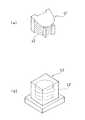
つぎに図2により、半導体製造用クリーンルーム内で扱われる荷3の形態を説明する。同図(a)の荷はカセット41と呼ばれるものである。ウェーハ42の一枚一枚を隙間を設けて収納し、カセット41毎そのまま液体に漬けてウェーハ処理が行えるようになっている。カセット41はウェーハ42一枚毎の出し入れと、前述したチャック手段による把持が可能な構造になっている。
同部(b)の荷はコンテナ43と呼ばれるものであり、密閉式の容器内に複数枚のウェーハ41を収納し、内部の環境を保持するものである。容器内から取り出したウェーハ41をそのまま又はカセット41に積み替えてウェーハ処理を行う。
カセット41又はコンテナ43のいずれも、クリーンルーム内の仕様に合わせて選択されて使用される。
【0024】
さらに図3により半導体製造用クリーンルーム内の搬送システムの全体を説明する。ウェーハ処理のために、工程Aから工程Cまでの4工程(ベイ)が配設され、各工程A〜Cに、バッファ機能と保管機能を兼ね備えたストッカ1A,1B,1C,1Dが設けられている。この4台のストッカ1A,1B,1C,1Dの上を順次経由して巡回するように配設された工程間搬送手段としての天井搬送装置2によって工程A〜C間のカセット41又はコンテナ43(図2)の搬送が行われる。
【0025】
ストッカ1A,1B,1C,1Dと天井搬送装置2の運行を統括するのが制御装置としてのメインコンピュータ4である。メインコンピュータ4は各ストッカ1A,1B,1C,1Dにおける受渡し部15の空き状況を認識しており、天井搬送装置2による空いた受渡し部15への選択的な荷の受渡しを可能にするとともに、各ストッカ1A,1B,1C,1Dによる荷の有無を確認した後の受渡し部15への選択的な搬送を可能にする。このような選択的は受渡し又は搬送は、各ストッカ1A,1B,1C,1Dの空き状況を検出するセンサの出力、及び、荷の受渡し指令信号等に入力応じて判断し所定の指示を指令するソフトウェアに基づいて簡単に実現できる。
【0026】
またストッカ1A,1B,1C,1Dの出入庫口16に対して工程内搬送手段5A,5B,5C,5Dが配設されており、工程内搬送手段5A,5B,5C,5Dの各々に製造装置6A1,6A2,6A3,6A4,6B1,6B2,6B3,6B4,6C1,6C2,6C3,6C4,6D1,6D2,6D3,6D4が配設されている。この工程内搬送手段5A,5B,5C,5Dには、アームを搭載した移動ロボットや軌道上を走行するアーム付台車等が使用される。
【0027】
以上のように、半導体製造用クリーンルーム内のカセット又はコンテナの搬送に前述した実施形態の搬送システムを使用すると、工程間搬送手段を構成する天井搬送装置2の1台以上の台車の稼働効率が上がり、搬送システムとして最も重要視される単位時間当たりの搬送量を上げる事が可能になる。特に半導体製造用クリーンルームは、ルーム内の設置面積が制限されており、効率の良い搬送システムを構築することは有効である。
【0028】
【発明の効果】
以上に説明したように、本発明のうち請求項1の発明は、天井搬送装置の走行に列設された2以上の荷の受渡し部からなる棚部を有するストッカにしたので、特定の受渡し部にカセット又はコンテナがある場合や特定の受渡し部に対するストッカ内搬送手段の搬送が行われている場合には、天井搬送装置の走行方向の停止位置を変えるだけでカセット又はコンテナの移載を他の受渡し部に対して行うことができ、天井搬送装置が特定のストッカの前で棚部が空くのを待つ必要がなくなり、複数のストッカに対する天井搬送装置の搬送効率を向上させるという効果を奏する。加えて、ストッカ内搬送手段が複数の受渡し部のいずれに対して走行方向の停止位置で移載可能になるため、ストッカ内搬送手段の構造が簡単になるという効果を奏する。これらの効果は、限られた空間内に機器が設置されるクリーンルーム内の搬送システムにおいて有効に発揮される。
【0029】
削除
【0030】
請求項2の発明は、請求項1の発明の効果に加えて、前記天井搬送装置の選択的なカセット又はコンテナの受渡しと、前記ストッカ内搬送手段の選択的なカセット又はコンテナの搬送が、ソフトウェア対応の制御装置で簡単にできるという効果を奏する。
【0031】
削除
【図面の簡単な説明】
【図1】 本発明システムを構成する機器の要部の斜視図である。
【図2】 荷の具体的形態を示す斜視図である。
【図3】 本発明システムの機器構成を示すレイアウト図である。
【図4】 従来システムを構成する機器の要部の斜視図である。
【符号の説明】
1 ストッカ
2 天井搬送装置
3 荷
4 メインコンピュータ(制御装置)
11 ストッカ内搬送装置
12 第1保管棚
13 第1保管棚
14 棚部
15 受渡し部
21 軌道台(レールと平行)
31 レール
41 カセット
43 コンテナ[0001]
BACKGROUND OF THE INVENTION
The present invention is a transport system having a plurality of stockers and a ceiling transport device that is provided so as to be able to travel through the plurality of stockers in sequence and that transfersa cassette or a container for storing wafers to each of the stockers. In particular, the present invention relates to a device that improves the transport efficiency of a ceiling transport device.
[0002]
[Prior art]
For example, in a clean room for semiconductor manufacturing, various manufacturing apparatuses are arranged in each process called a bay, and a specific wafer process is performed in each manufacturing apparatus. Usually, since the processing speed of each manufacturing apparatus is different, a stocker having a buffer function and a storage function is provided for each process.
[0003]
The transfer from the stocker to each stocker is carried so as to pass through a plurality of stockers in sequence, and a ceiling transport device for deliveringa cassette or a container forstoring wafers to each of the stockers. It is a transport system that is performed by.
[0004]
A conventional example of such a transport system will be described with reference to FIG. In the figure, the transport system includes a plurality of
[0005]
The
The intra-stocker conveying means 104 can cope with transfer of the
On the other hand, the
[0006]
In the above-described transport system, the operation when the
First, the
Next, the intra-stocker conveying means 104 receives the
[0007]
[Problems to be solved by the invention]
However, in the conventional transport system described above, each of the plurality of
[0008]
SUMMARY OF THE INVENTION Accordingly, an object of the present invention is to provide a transport system to a stocker that shortens the load transfer time from an overhead transport vehicle to a plurality of stockers and improves the transport efficiency.
[0009]
[Means for Solving the Problems]
In order to achieve the above-mentioned object, the invention of
With multiple stockers,
Rutotomoni travel freely provided to via this plurality of stockerssuccessively vertically movably have hanging chuck means is lowered, ceiling transport for transferring thecassette or container housing the wafers with respect to each of said stocker Equipment,
A transport system comprising:
The stocker includes a storage rack for storing the number of thecassette or container, and the ceiling transport device and thecassette or shelf for delivering thecontainer,said cassette between said ledge portion and the storage shelfor In order to transport thecontainer , it is possible to travel along the storage shelf, and includes a transporting meansin the stockerthat travels in parallel with the traveling direction of the ceiling transport device ,
The shelf has a delivery section for two or morecassettes or containers arranged in a line along the traveling direction of the ceiling transport device,
The ceiling transport device iscapable of selectively delivering acassette or containerso that acassette or containercan be delivered to avacant delivery unitamong two or morecassettes or container delivery units,
The intra-stocker transport device is capable of selectively transporting either one of two or morecassettes or a container delivery unit.
Thereby, when there is acassette or container in the specific delivery unitor when the transport means in the stocker for the specific delivery unit is being transported, the ceiling transport device changes the stop position in the traveling direction, Acassette or a containercan be transferred to an empty delivery section.
Further, the intra-stocker transport means can be transferred to any of the two or more cargo delivery sections by simply changing the stop position in the traveling direction. Furthermore, even when the stocker is installed in a clean room, it is possible to increase the transfer efficiency of the ceiling transfer device and effectively use the limited space.
[0010]
Delete [0011]
The invention of claim2, in
As a result, the availability of the shelves of the plurality of stockers and the information on whichcassettes or containers are located in the shelves of each stocker, such as a main computer that supervises the plurality of stockers and the ceiling transport device, etc. The control device is based on predetermined software, and recognizes a delivery position of a specificcassette or container so that thecassette or container is not confused.
[0012]
Delete [0013]
DETAILED DESCRIPTION OF THE INVENTION
Embodiments of the present invention will be described together with illustrated examples.
FIG. 1 is a perspective view of a main part of a device constituting the system of the present invention, FIG. 2 is a perspective view showing a specific form of a load, and FIG. 3 is a layout diagram showing a device configuration of the system of the present invention. It is.
[0014]
In FIG. 1, a transport system showing an embodiment of the present invention is described by exemplifying one of a plurality of
[0015]
That is, the transport system is mainly configured by a plurality of
[0016]
The ceiling conveying device 2 allows one or more carts 32 to run along the
[0017]
The carriage 32 travels with the chuck means 33 holding the load(cassette for storing wafers) 3 and raising it to the upper limit position of the carriage 32. When the carriage 32 travels along the
[0018]
A plurality of
[0019]
Further, the
[0020]
The intra-stocker transport means 11 is configured to transfer the load 3 to the
Moreover, the
[0021]
Next, the operation of the above-described transfer system will be described, particularly when the load 3 from the ceiling transfer device 2 to the
First, the carriage 32 of the ceiling conveyance device 2 that has carried the load 3 recognizes a vacant place in the
Next, when the chuck means 33 for gripping the load 3 from the carriage 32 is lowered and the load 3 is placed on the
The intra-stocker transporting means 11 travels along the
[0022]
Therefore, even when the transporter 11 in the stocker transfers the load 3 by the
[0023]
Next, the form of the load 3 handled in the clean room for semiconductor manufacturing will be described with reference to FIG. The load shown in FIG. 4A is called a
The load of the part (b) is called a
Either the
[0024]
Furthermore, the whole conveyance system in the clean room for semiconductor manufacturing will be described with reference to FIG. For wafer processing, four steps (bays) from step A to step C are arranged, and stockers 1A, 1B, 1C, and 1D having a buffer function and a storage function are provided in each step A to C. Yes. The
[0025]
A main computer 4 as a control device supervises the operation of the stockers 1A, 1B, 1C, 1D and the ceiling transport device 2. The main computer 4 recognizes the vacant state of the
[0026]
Further, in-process transfer means 5A, 5B, 5C, 5D are arranged for the loading / unloading
[0027]
As described above, when the transport system of the above-described embodiment is used for transporting a cassette or container in a semiconductor manufacturing clean room, the operating efficiency of one or more carts of the ceiling transport device 2 constituting the inter-process transport means is increased. Therefore, it is possible to increase the transport amount per unit time, which is regarded as most important as a transport system. Particularly in a clean room for semiconductor manufacturing, the installation area in the room is limited, and it is effective to construct an efficient transfer system.
[0028]
【The invention's effect】
As describedabove, the invention of
[0029]
Delete [0030]
According to asecond aspect of the invention, in addition to the effect of the invention of
[0031]
Delete [Brief description of drawings]
FIG. 1 is a perspective view of a main part of a device constituting a system of the present invention.
FIG. 2 is a perspective view showing a specific form of a load.
FIG. 3 is a layout diagram showing a device configuration of the system of the present invention.
FIG. 4 is a perspective view of a main part of equipment constituting a conventional system.
[Explanation of symbols]
1 Stocker 2 Ceiling Transporter 3 Load 4 Main Computer (Control Device)
11
31
Claims (2)
Translated fromJapaneseこの複数のストッカを順次経由するよう走行自在に設けられるとともに、昇降自在につり下げられたチャック手段を有し、前記ストッカの各々に対してウェーハを収納するカセット又はコンテナの受渡しを行う天井搬送装置と、
を有する搬送システムであって、
前記ストッカは、前記カセット又はコンテナの多数を保管する保管棚と、前記天井搬送装置と前記カセット又はコンテナの受渡しを行うための棚部と、前記棚部と前記保管棚との間で前記カセット又はコンテナの搬送を行うために前記保管棚に沿って走行自在で、前記天井搬送装置の走行方向と平行に走行するストッカ内搬送手段とを備えてなり、
前記棚部は、前記天井搬送装置の走行方向に沿って列設された2以上のカセット又はコンテナの受渡し部を有し、
前記天井搬送装置は、2以上のカセット又はコンテナの受渡し部のうち空いている受渡し部に対してカセット又はコンテナの受渡しができるように、選択的なカセット又はコンテナの受渡しが可能であり、
前記ストッカ内搬送装置は、2以上のカセット又はコンテナの受渡し部のいずれかに対して選択的な搬送が可能になっているストッカへの搬送システム。With multiple stockers,
Rutotomoni travel freely provided to via this plurality of stockerssuccessively vertically movably have hanging chuck means is lowered, ceiling transport for transferring thecassette or container housing the wafers with respect to each of said stocker Equipment,
A transport system comprising:
The stocker includes a storage rack for storing the number of thecassette or container, and the ceiling transport device and thecassette or shelf for delivering thecontainer,said cassette between said ledge portion and the storage shelfor In order to transport thecontainer , it is possible to travel along the storage shelf, and includes a transporting meansin the stockerthat travels in parallel with the traveling direction of the ceiling transport device ,
The shelf has a delivery section for two or morecassettes or containers arranged in a line along the traveling direction of the ceiling transport device,
The ceiling transport device iscapable of selectively delivering acassette or containerso that acassette or containercan be delivered to avacant delivery unitamong two or morecassettes or container delivery units,
The transporter in the stocker is a transport system to a stocker that can selectively transport either one of two or morecassettes or a container delivery unit.
Priority Applications (1)
| Application Number | Priority Date | Filing Date | Title |
|---|---|---|---|
| JP16369896AJP3669057B2 (en) | 1996-06-03 | 1996-06-03 | Transport system to stocker |
Applications Claiming Priority (1)
| Application Number | Priority Date | Filing Date | Title |
|---|---|---|---|
| JP16369896AJP3669057B2 (en) | 1996-06-03 | 1996-06-03 | Transport system to stocker |
Publications (2)
| Publication Number | Publication Date |
|---|---|
| JPH09315521A JPH09315521A (en) | 1997-12-09 |
| JP3669057B2true JP3669057B2 (en) | 2005-07-06 |
Family
ID=15778921
Family Applications (1)
| Application Number | Title | Priority Date | Filing Date |
|---|---|---|---|
| JP16369896AExpired - Fee RelatedJP3669057B2 (en) | 1996-06-03 | 1996-06-03 | Transport system to stocker |
Country Status (1)
| Country | Link |
|---|---|
| JP (1) | JP3669057B2 (en) |
Cited By (2)
| Publication number | Priority date | Publication date | Assignee | Title |
|---|---|---|---|---|
| WO2019003753A1 (en)* | 2017-06-30 | 2019-01-03 | 村田機械株式会社 | Conveying system and conveying method |
| WO2024142502A1 (en) | 2022-12-27 | 2024-07-04 | 村田機械株式会社 | Conveyance vehicle system |
Families Citing this family (30)
| Publication number | Priority date | Publication date | Assignee | Title |
|---|---|---|---|---|
| US5912510A (en)* | 1996-05-29 | 1999-06-15 | Motorola, Inc. | Bonding structure for an electronic device |
| AU2691800A (en)* | 1999-02-26 | 2000-09-14 | Nikon Corporation | Exposure system, lithography system and conveying method, and device production method and device |
| KR100882376B1 (en)* | 2002-06-19 | 2009-02-05 | 브룩스 오토메이션, 인크. | Automatic material handling system for semiconductor manufacturing based on combination of vertical rotary storage lathe and overhead hoist |
| WO2004034438A2 (en) | 2002-10-11 | 2004-04-22 | Brooks Automation, Inc. | Access to one or more levels of material storage shelves by an overhead hoist transport vehicle from a single track position |
| TWI246501B (en) | 2003-02-03 | 2006-01-01 | Murata Machinery Ltd | Overhead traveling carriage system |
| DE10329868A1 (en)* | 2003-07-02 | 2005-01-20 | Dynamic Microsystems Semiconductor Equipment Gmbh | Storage system for wafers |
| JP4537731B2 (en)* | 2004-03-04 | 2010-09-08 | シャープ株式会社 | Control method of transfer device |
| EP1883958A2 (en)* | 2005-05-16 | 2008-02-06 | Asyst Technologies, Inc. | Modular terminal for high-throughput amhs |
| JP2009062155A (en)* | 2007-09-06 | 2009-03-26 | Asyst Technologies Japan Inc | Storage set and carrying system with storage |
| JP2009062153A (en)* | 2007-09-06 | 2009-03-26 | Asyst Technologies Japan Inc | Storage |
| JP5470691B2 (en)* | 2007-09-06 | 2014-04-16 | 村田機械株式会社 | Storage and transport system with storage |
| TW200911654A (en) | 2007-09-06 | 2009-03-16 | Asyst Technologies Japan Inc | Storage, transporting system and storage set |
| JP5286721B2 (en)* | 2007-09-13 | 2013-09-11 | 村田機械株式会社 | Transport system |
| JP5303893B2 (en)* | 2007-10-18 | 2013-10-02 | 村田機械株式会社 | Storehouse |
| JP2009096610A (en)* | 2007-10-18 | 2009-05-07 | Asyst Technologies Japan Inc | Storage apparatus set and conveying system with storage apparatus |
| JP5369419B2 (en)* | 2007-10-18 | 2013-12-18 | 村田機械株式会社 | Storage system with storage, storage set and storage |
| JP5217416B2 (en)* | 2007-12-25 | 2013-06-19 | 村田機械株式会社 | Storage and entry / exit methods |
| TWI481539B (en)* | 2007-12-25 | 2015-04-21 | Murata Machinery Ltd | Storage and method for loading and unloading |
| JP5234328B2 (en) | 2008-04-11 | 2013-07-10 | 株式会社ダイフク | Goods storage equipment |
| JP2010062322A (en)* | 2008-09-03 | 2010-03-18 | Ryusyo Industrial Co Ltd | Semiconductor wafer transfer system |
| JP5157787B2 (en)* | 2008-09-26 | 2013-03-06 | 村田機械株式会社 | Transport system |
| JP5332930B2 (en)* | 2009-06-15 | 2013-11-06 | 村田機械株式会社 | Automatic warehouse |
| JP5316907B2 (en)* | 2011-03-17 | 2013-10-16 | 株式会社ダイフク | Goods transport equipment |
| WO2013150859A1 (en)* | 2012-04-05 | 2013-10-10 | 村田機械株式会社 | Conveyance system |
| JP2015117073A (en)* | 2012-04-05 | 2015-06-25 | 村田機械株式会社 | Carrier system |
| EP2860136B1 (en)* | 2012-06-08 | 2020-08-05 | Murata Machinery, Ltd. | Conveyance system and temporary storage method of articles in conveyance system |
| KR101609338B1 (en)* | 2015-03-16 | 2016-04-05 | 크린팩토메이션 주식회사 | Apparatus for storing and handling wafer carrier at ceiling |
| CN108349649B (en)* | 2015-08-27 | 2020-07-28 | 村田机械株式会社 | Taking-out device and storage device |
| SG11201912679WA (en)* | 2017-06-30 | 2020-01-30 | Murata Machinery Ltd | Transport system and transport method |
| WO2025057607A1 (en)* | 2023-09-12 | 2025-03-20 | 村田機械株式会社 | Stocker and storage conveyance system |
- 1996
- 1996-06-03JPJP16369896Apatent/JP3669057B2/ennot_activeExpired - Fee Related
Cited By (4)
| Publication number | Priority date | Publication date | Assignee | Title |
|---|---|---|---|---|
| WO2019003753A1 (en)* | 2017-06-30 | 2019-01-03 | 村田機械株式会社 | Conveying system and conveying method |
| JPWO2019003753A1 (en)* | 2017-06-30 | 2020-04-23 | 村田機械株式会社 | Transport system and transport method |
| WO2024142502A1 (en) | 2022-12-27 | 2024-07-04 | 村田機械株式会社 | Conveyance vehicle system |
| EP4624366A1 (en) | 2022-12-27 | 2025-10-01 | Murata Machinery, Ltd. | Conveyance vehicle system |
Also Published As
| Publication number | Publication date |
|---|---|
| JPH09315521A (en) | 1997-12-09 |
Similar Documents
| Publication | Publication Date | Title |
|---|---|---|
| JP3669057B2 (en) | Transport system to stocker | |
| US11978652B2 (en) | Automatic handling buffer for bare stocker | |
| US6169935B1 (en) | Control method of stocker entry task and stocker exit task in semiconductor wafer cassette transportation apparatus | |
| US9299597B2 (en) | Scalable stockers with automatic handling buffer | |
| EP1627834B1 (en) | Carrying system | |
| KR100556221B1 (en) | Device for Carrying Semiconductor Wafer Carrier | |
| US9845193B2 (en) | Conveyance system | |
| US8622682B2 (en) | Storage, storage set and transporting system | |
| JP7213056B2 (en) | SUBSTRATE PROCESSING APPARATUS AND SUBSTRATE PROCESSING METHOD | |
| JP2009514235A (en) | Horizontal alignment stocker | |
| JPH10203610A (en) | Automatic storage shelf and automatic storage method | |
| JP2005001886A (en) | Carrying system and storage device used therefor | |
| JP2005029319A (en) | Conveying system | |
| JP2000124284A (en) | Transfer device | |
| JPWO2004080852A1 (en) | Automatic storage system | |
| EP2245656B1 (en) | Automatic handling buffer for bare stocker | |
| JP2008100848A (en) | Automatic storage system | |
| JP4154269B2 (en) | Manufacturing equipment transfer system | |
| JP2611747B2 (en) | Wafer storage box transfer device | |
| JP4030672B2 (en) | Cassette storage device | |
| WO2023188769A1 (en) | Conveyance system | |
| KR20240096112A (en) | Container transfer system and container transfer method | |
| JP2002326707A (en) | Automated storage and retrieval warehouse | |
| TW202423811A (en) | Transport vehicle system | |
| JP2003095411A (en) | Article storage device |
Legal Events
| Date | Code | Title | Description |
|---|---|---|---|
| A977 | Report on retrieval | Free format text:JAPANESE INTERMEDIATE CODE: A971007 Effective date:20040716 | |
| A131 | Notification of reasons for refusal | Free format text:JAPANESE INTERMEDIATE CODE: A131 Effective date:20040810 | |
| A521 | Written amendment | Free format text:JAPANESE INTERMEDIATE CODE: A523 Effective date:20041008 | |
| A521 | Written amendment | Free format text:JAPANESE INTERMEDIATE CODE: A523 Effective date:20041026 | |
| TRDD | Decision of grant or rejection written | ||
| A01 | Written decision to grant a patent or to grant a registration (utility model) | Free format text:JAPANESE INTERMEDIATE CODE: A01 Effective date:20050322 | |
| A61 | First payment of annual fees (during grant procedure) | Free format text:JAPANESE INTERMEDIATE CODE: A61 Effective date:20050404 | |
| R150 | Certificate of patent or registration of utility model | Free format text:JAPANESE INTERMEDIATE CODE: R150 | |
| S531 | Written request for registration of change of domicile | Free format text:JAPANESE INTERMEDIATE CODE: R313531 | |
| S111 | Request for change of ownership or part of ownership | Free format text:JAPANESE INTERMEDIATE CODE: R313113 | |
| R371 | Transfer withdrawn | Free format text:JAPANESE INTERMEDIATE CODE: R371 | |
| S531 | Written request for registration of change of domicile | Free format text:JAPANESE INTERMEDIATE CODE: R313531 | |
| S111 | Request for change of ownership or part of ownership | Free format text:JAPANESE INTERMEDIATE CODE: R313113 | |
| R350 | Written notification of registration of transfer | Free format text:JAPANESE INTERMEDIATE CODE: R350 | |
| R350 | Written notification of registration of transfer | Free format text:JAPANESE INTERMEDIATE CODE: R350 | |
| FPAY | Renewal fee payment (event date is renewal date of database) | Free format text:PAYMENT UNTIL: 20080422 Year of fee payment:3 | |
| S111 | Request for change of ownership or part of ownership | Free format text:JAPANESE INTERMEDIATE CODE: R313113 | |
| FPAY | Renewal fee payment (event date is renewal date of database) | Free format text:PAYMENT UNTIL: 20080422 Year of fee payment:3 | |
| R350 | Written notification of registration of transfer | Free format text:JAPANESE INTERMEDIATE CODE: R350 | |
| FPAY | Renewal fee payment (event date is renewal date of database) | Free format text:PAYMENT UNTIL: 20080422 Year of fee payment:3 | |
| FPAY | Renewal fee payment (event date is renewal date of database) | Free format text:PAYMENT UNTIL: 20090422 Year of fee payment:4 | |
| FPAY | Renewal fee payment (event date is renewal date of database) | Free format text:PAYMENT UNTIL: 20090422 Year of fee payment:4 | |
| FPAY | Renewal fee payment (event date is renewal date of database) | Free format text:PAYMENT UNTIL: 20100422 Year of fee payment:5 | |
| FPAY | Renewal fee payment (event date is renewal date of database) | Free format text:PAYMENT UNTIL: 20100422 Year of fee payment:5 | |
| S111 | Request for change of ownership or part of ownership | Free format text:JAPANESE INTERMEDIATE CODE: R313113 | |
| FPAY | Renewal fee payment (event date is renewal date of database) | Free format text:PAYMENT UNTIL: 20100422 Year of fee payment:5 | |
| R360 | Written notification for declining of transfer of rights | Free format text:JAPANESE INTERMEDIATE CODE: R360 | |
| FPAY | Renewal fee payment (event date is renewal date of database) | Free format text:PAYMENT UNTIL: 20100422 Year of fee payment:5 | |
| R360 | Written notification for declining of transfer of rights | Free format text:JAPANESE INTERMEDIATE CODE: R360 | |
| R371 | Transfer withdrawn | Free format text:JAPANESE INTERMEDIATE CODE: R371 | |
| FPAY | Renewal fee payment (event date is renewal date of database) | Free format text:PAYMENT UNTIL: 20100422 Year of fee payment:5 | |
| S111 | Request for change of ownership or part of ownership | Free format text:JAPANESE INTERMEDIATE CODE: R313113 | |
| FPAY | Renewal fee payment (event date is renewal date of database) | Free format text:PAYMENT UNTIL: 20100422 Year of fee payment:5 | |
| R350 | Written notification of registration of transfer | Free format text:JAPANESE INTERMEDIATE CODE: R350 | |
| FPAY | Renewal fee payment (event date is renewal date of database) | Free format text:PAYMENT UNTIL: 20100422 Year of fee payment:5 | |
| FPAY | Renewal fee payment (event date is renewal date of database) | Free format text:PAYMENT UNTIL: 20110422 Year of fee payment:6 | |
| FPAY | Renewal fee payment (event date is renewal date of database) | Free format text:PAYMENT UNTIL: 20120422 Year of fee payment:7 | |
| FPAY | Renewal fee payment (event date is renewal date of database) | Free format text:PAYMENT UNTIL: 20120422 Year of fee payment:7 | |
| FPAY | Renewal fee payment (event date is renewal date of database) | Free format text:PAYMENT UNTIL: 20130422 Year of fee payment:8 | |
| FPAY | Renewal fee payment (event date is renewal date of database) | Free format text:PAYMENT UNTIL: 20130422 Year of fee payment:8 | |
| S111 | Request for change of ownership or part of ownership | Free format text:JAPANESE INTERMEDIATE CODE: R313111 | |
| FPAY | Renewal fee payment (event date is renewal date of database) | Free format text:PAYMENT UNTIL: 20130422 Year of fee payment:8 | |
| R350 | Written notification of registration of transfer | Free format text:JAPANESE INTERMEDIATE CODE: R350 | |
| FPAY | Renewal fee payment (event date is renewal date of database) | Free format text:PAYMENT UNTIL: 20130422 Year of fee payment:8 | |
| FPAY | Renewal fee payment (event date is renewal date of database) | Free format text:PAYMENT UNTIL: 20140422 Year of fee payment:9 | |
| R250 | Receipt of annual fees | Free format text:JAPANESE INTERMEDIATE CODE: R250 | |
| R250 | Receipt of annual fees | Free format text:JAPANESE INTERMEDIATE CODE: R250 | |
| LAPS | Cancellation because of no payment of annual fees |