JP3668842B2 - Refrigeration equipment - Google Patents
Refrigeration equipmentDownload PDFInfo
- Publication number
- JP3668842B2 JP3668842B2JP2001051380AJP2001051380AJP3668842B2JP 3668842 B2JP3668842 B2JP 3668842B2JP 2001051380 AJP2001051380 AJP 2001051380AJP 2001051380 AJP2001051380 AJP 2001051380AJP 3668842 B2JP3668842 B2JP 3668842B2
- Authority
- JP
- Japan
- Prior art keywords
- capacity
- pressure value
- value
- pressure
- time
- Prior art date
- Legal status (The legal status is an assumption and is not a legal conclusion. Google has not performed a legal analysis and makes no representation as to the accuracy of the status listed.)
- Expired - Lifetime
Links
Images


Classifications
- F—MECHANICAL ENGINEERING; LIGHTING; HEATING; WEAPONS; BLASTING
- F25—REFRIGERATION OR COOLING; COMBINED HEATING AND REFRIGERATION SYSTEMS; HEAT PUMP SYSTEMS; MANUFACTURE OR STORAGE OF ICE; LIQUEFACTION SOLIDIFICATION OF GASES
- F25B—REFRIGERATION MACHINES, PLANTS OR SYSTEMS; COMBINED HEATING AND REFRIGERATION SYSTEMS; HEAT PUMP SYSTEMS
- F25B49/00—Arrangement or mounting of control or safety devices
- F25B49/02—Arrangement or mounting of control or safety devices for compression type machines, plants or systems
- F25B49/022—Compressor control arrangements
- F—MECHANICAL ENGINEERING; LIGHTING; HEATING; WEAPONS; BLASTING
- F25—REFRIGERATION OR COOLING; COMBINED HEATING AND REFRIGERATION SYSTEMS; HEAT PUMP SYSTEMS; MANUFACTURE OR STORAGE OF ICE; LIQUEFACTION SOLIDIFICATION OF GASES
- F25B—REFRIGERATION MACHINES, PLANTS OR SYSTEMS; COMBINED HEATING AND REFRIGERATION SYSTEMS; HEAT PUMP SYSTEMS
- F25B1/00—Compression machines, plants or systems with non-reversible cycle
- F—MECHANICAL ENGINEERING; LIGHTING; HEATING; WEAPONS; BLASTING
- F25—REFRIGERATION OR COOLING; COMBINED HEATING AND REFRIGERATION SYSTEMS; HEAT PUMP SYSTEMS; MANUFACTURE OR STORAGE OF ICE; LIQUEFACTION SOLIDIFICATION OF GASES
- F25B—REFRIGERATION MACHINES, PLANTS OR SYSTEMS; COMBINED HEATING AND REFRIGERATION SYSTEMS; HEAT PUMP SYSTEMS
- F25B2400/00—General features or devices for refrigeration machines, plants or systems, combined heating and refrigeration systems or heat-pump systems, i.e. not limited to a particular subgroup of F25B
- F25B2400/03—Suction accumulators with deflectors
- F—MECHANICAL ENGINEERING; LIGHTING; HEATING; WEAPONS; BLASTING
- F25—REFRIGERATION OR COOLING; COMBINED HEATING AND REFRIGERATION SYSTEMS; HEAT PUMP SYSTEMS; MANUFACTURE OR STORAGE OF ICE; LIQUEFACTION SOLIDIFICATION OF GASES
- F25B—REFRIGERATION MACHINES, PLANTS OR SYSTEMS; COMBINED HEATING AND REFRIGERATION SYSTEMS; HEAT PUMP SYSTEMS
- F25B2400/00—General features or devices for refrigeration machines, plants or systems, combined heating and refrigeration systems or heat-pump systems, i.e. not limited to a particular subgroup of F25B
- F25B2400/07—Details of compressors or related parts
- F25B2400/075—Details of compressors or related parts with parallel compressors
- F—MECHANICAL ENGINEERING; LIGHTING; HEATING; WEAPONS; BLASTING
- F25—REFRIGERATION OR COOLING; COMBINED HEATING AND REFRIGERATION SYSTEMS; HEAT PUMP SYSTEMS; MANUFACTURE OR STORAGE OF ICE; LIQUEFACTION SOLIDIFICATION OF GASES
- F25B—REFRIGERATION MACHINES, PLANTS OR SYSTEMS; COMBINED HEATING AND REFRIGERATION SYSTEMS; HEAT PUMP SYSTEMS
- F25B2400/00—General features or devices for refrigeration machines, plants or systems, combined heating and refrigeration systems or heat-pump systems, i.e. not limited to a particular subgroup of F25B
- F25B2400/16—Receivers
- F—MECHANICAL ENGINEERING; LIGHTING; HEATING; WEAPONS; BLASTING
- F25—REFRIGERATION OR COOLING; COMBINED HEATING AND REFRIGERATION SYSTEMS; HEAT PUMP SYSTEMS; MANUFACTURE OR STORAGE OF ICE; LIQUEFACTION SOLIDIFICATION OF GASES
- F25B—REFRIGERATION MACHINES, PLANTS OR SYSTEMS; COMBINED HEATING AND REFRIGERATION SYSTEMS; HEAT PUMP SYSTEMS
- F25B2400/00—General features or devices for refrigeration machines, plants or systems, combined heating and refrigeration systems or heat-pump systems, i.e. not limited to a particular subgroup of F25B
- F25B2400/22—Refrigeration systems for supermarkets
- F—MECHANICAL ENGINEERING; LIGHTING; HEATING; WEAPONS; BLASTING
- F25—REFRIGERATION OR COOLING; COMBINED HEATING AND REFRIGERATION SYSTEMS; HEAT PUMP SYSTEMS; MANUFACTURE OR STORAGE OF ICE; LIQUEFACTION SOLIDIFICATION OF GASES
- F25B—REFRIGERATION MACHINES, PLANTS OR SYSTEMS; COMBINED HEATING AND REFRIGERATION SYSTEMS; HEAT PUMP SYSTEMS
- F25B2600/00—Control issues
- F25B2600/02—Compressor control
- F25B2600/021—Inverters therefor
- F—MECHANICAL ENGINEERING; LIGHTING; HEATING; WEAPONS; BLASTING
- F25—REFRIGERATION OR COOLING; COMBINED HEATING AND REFRIGERATION SYSTEMS; HEAT PUMP SYSTEMS; MANUFACTURE OR STORAGE OF ICE; LIQUEFACTION SOLIDIFICATION OF GASES
- F25B—REFRIGERATION MACHINES, PLANTS OR SYSTEMS; COMBINED HEATING AND REFRIGERATION SYSTEMS; HEAT PUMP SYSTEMS
- F25B2600/00—Control issues
- F25B2600/02—Compressor control
- F25B2600/025—Compressor control by controlling speed
- F25B2600/0251—Compressor control by controlling speed with on-off operation
- F—MECHANICAL ENGINEERING; LIGHTING; HEATING; WEAPONS; BLASTING
- F25—REFRIGERATION OR COOLING; COMBINED HEATING AND REFRIGERATION SYSTEMS; HEAT PUMP SYSTEMS; MANUFACTURE OR STORAGE OF ICE; LIQUEFACTION SOLIDIFICATION OF GASES
- F25B—REFRIGERATION MACHINES, PLANTS OR SYSTEMS; COMBINED HEATING AND REFRIGERATION SYSTEMS; HEAT PUMP SYSTEMS
- F25B2700/00—Sensing or detecting of parameters; Sensors therefor
- F25B2700/19—Pressures
- F25B2700/193—Pressures of the compressor
- F25B2700/1933—Suction pressures
- F—MECHANICAL ENGINEERING; LIGHTING; HEATING; WEAPONS; BLASTING
- F25—REFRIGERATION OR COOLING; COMBINED HEATING AND REFRIGERATION SYSTEMS; HEAT PUMP SYSTEMS; MANUFACTURE OR STORAGE OF ICE; LIQUEFACTION SOLIDIFICATION OF GASES
- F25B—REFRIGERATION MACHINES, PLANTS OR SYSTEMS; COMBINED HEATING AND REFRIGERATION SYSTEMS; HEAT PUMP SYSTEMS
- F25B5/00—Compression machines, plants or systems, with several evaporator circuits, e.g. for varying refrigerating capacity
- F25B5/02—Compression machines, plants or systems, with several evaporator circuits, e.g. for varying refrigerating capacity arranged in parallel
- Y—GENERAL TAGGING OF NEW TECHNOLOGICAL DEVELOPMENTS; GENERAL TAGGING OF CROSS-SECTIONAL TECHNOLOGIES SPANNING OVER SEVERAL SECTIONS OF THE IPC; TECHNICAL SUBJECTS COVERED BY FORMER USPC CROSS-REFERENCE ART COLLECTIONS [XRACs] AND DIGESTS
- Y02—TECHNOLOGIES OR APPLICATIONS FOR MITIGATION OR ADAPTATION AGAINST CLIMATE CHANGE
- Y02B—CLIMATE CHANGE MITIGATION TECHNOLOGIES RELATED TO BUILDINGS, e.g. HOUSING, HOUSE APPLIANCES OR RELATED END-USER APPLICATIONS
- Y02B30/00—Energy efficient heating, ventilation or air conditioning [HVAC]
- Y02B30/70—Efficient control or regulation technologies, e.g. for control of refrigerant flow, motor or heating
Landscapes
- Engineering & Computer Science (AREA)
- Physics & Mathematics (AREA)
- Mechanical Engineering (AREA)
- Thermal Sciences (AREA)
- General Engineering & Computer Science (AREA)
- Air Conditioning Control Device (AREA)
- Control Of Positive-Displacement Pumps (AREA)
Description
Translated fromJapanese【0001】
【発明の属する技術分野】
本発明は冷凍装置に係わり、特にショーケースを複数台接続し負荷変動の大きな店舗用冷凍装置に好適である。
【0002】
【従来の技術】
従来、冷凍機では設定圧力として容量アップ圧力値、容量ダウン圧力値を定め、吸入圧力が容量アップ圧力値以上である場合は、圧縮機の運転台数あるいは運転周波数を増加して運転容量を上げ、容量ダウン圧力値以下である場合は、運転台数、運転周波数を減少すること、さらに設定圧力値は、店舗内の温度や屋外の温度等を検出して自動的に変化するようにすることが知られ、例えば特開平8−271063号公報に記載されている。
【0003】
【発明が解決しようとする課題】
上記従来の技術では、負荷が大きく、かつ頻繁に変動したり、より最適な運転圧力となるように木目細かく運転するため設定圧力範囲を狭めた場合には、圧縮機のオンオフを繰り返したり、インバータ周波数を頻繁に変えざるを得なかった。したがって、圧縮機をオンオフする場合は、その起動の消費電力の損失が、インバータ圧縮機においても回転数変化に伴う消費電力の損失が大きくなる恐れがあった。
【0004】
本発明の目的は、変動の大きな負荷に対しても運転圧力を最適にし、より一層省エネであり、信頼性の高い冷凍装置を提供することにある。
【0005】
【課題を解決するための手段】
上記目的を達成するための本発明は、圧縮機、凝縮器、受液器、膨張弁及び蒸発器を有する冷凍サイクルと、前記圧縮機の吸入側の圧力を検出する吸入圧力センサを備え、吸入圧力が容量アップ圧力値以上である場合は、圧縮機の運転台数あるいは運転周波数を増加し、容量ダウン圧力値以下である場合は、運転台数あるいは運転周波数を減少する冷凍装置において、吸入圧力が容量アップ圧力値以上にある時間と、容量ダウン圧力値以下にある時間と、を比較演算し、容量ダウン圧力値以下にある時間が容量アップ圧力値以上にある時間よりも長ければ、容量アップ圧力値あるいは容量ダウン圧力値のうちどちらか一方を大きな値とするものである。
【0006】
これにより、負荷が少ないときでも必要最小限の運転容量で運転する時間が長くなり、省エネ効果、つまり電力量を低減することができ、圧縮機のオン/オフ回数あるいは運転周波数の変化が少なくなるので、冷凍機が発生する冷凍能力に対して電力ロスを小さくできる。
【0007】
また、上記のものにおいて、容量ダウン圧力値以下にある時間が容量アップ圧力値以上にある時間よりも短ければ、容量アップ圧力値あるいは容量ダウン圧力値のうちどちらか一方を小さな値とすることが望ましい。
【0010】
さらに、本発明は、圧縮機を複数台備え、前記吸入圧力が前記容量アップ圧力値以上となってから前記複数台の圧縮機のうちいずれかのものが停止するまでの時間を求め、この時間が所定値よりも短い場合は、容量アップ圧力値あるいは容量ダウン圧力値のうちどちらか一方を大きな値とするものである。
【0011】
さらに、上記のものにおいて、前記停止するまでの時間が所定値よりも長い場合は、容量アップ圧力値あるいは容量ダウン圧力値のうちどちらか一方を小さな値とすることが望ましい。
【0012】
さらに、本発明は、吸入圧力が容量アップ圧力値以上となってから容量ダウン圧力値以下になるまでの時間を求め、この時間が所定値よりも短い場合は、容量アップ圧力値あるいは容量ダウン圧力値のうちどちらか一方を大きな値とするものである。
【0013】
さらに、上記のものにおいて、前記容量ダウン圧力値以下になるまでの時間が所定値よりも長い場合は、容量アップ圧力値あるいは容量ダウン圧力値のうちどちらか一方を小さな値とすることことが望ましい。
【0014】
【発明の実施の形態】
以下、本発明の実施の形態を図1ないし7を参照して説明する。
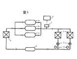
図1は、本発明における冷凍装置の基本冷凍サイクルの一例を示す図であり、図1において、1a、1b、1cは圧縮機であり、その他凝縮器2、受液器3、電磁弁4、膨張弁5、蒸発器6の主要機器で冷凍サイクルが形成されている。また、圧縮機吸入側の配管には圧力センサ7が取付けられ、圧力センサ7にて検出された吸入圧力値をユニットコントローラ8にて処理し、その時の圧縮機の運転容量を決定する。つまり、圧縮機の吸入圧力が容量アップ圧力値以上である場合は、圧縮機の運転台数あるいは運転周波数を増加し、容量ダウン圧力値以下である場合は、運転台数あるいは運転周波数を減少する。
【0015】
次に、変動の大きな負荷に対しても、より一層省エネを図るため、容量アップ圧力値、容量ダウン圧力値そのものを変化させることを説明する。
図2は、一実施の形態による冷凍装置の運転容量制御の例を示し、上図が横軸を時間、縦軸を吸入圧力としたもので、吸入圧力の時間的な変化の一例を示している。同じく図3も吸入圧力の時間的な変化を示し、容量アップ圧力値、容量ダウン圧力値、さらに圧縮機を停止する停止圧力値の関係を示している。
【0016】
吸入圧力が容量アップ圧力値以上になったとき、図2の中図のように複数の圧縮機があるマルチ冷凍機の場合は圧縮機の運転台数を増加して、図でNo.1のみから、No.1とNo.2、さらに、No.3を追加して運転容量を上げ、下図のようにインバータ冷凍機(圧縮機)の場合は運転周波数を増加して行く。
【0017】
逆に、吸入圧力が容量ダウン圧力値以下になったときは、マルチ冷凍機の場合は圧縮機運転台数を減少し、インバータ冷凍機の場合は運転周波数を減少し、運転容量を下げるといった制御を行う。
【0018】
次に、容量アップ圧力値、容量ダウン圧力値を上方へシフトした場合の圧縮機のオン/オフ回数減少効果、及びインバータ冷凍機の場合について図7により説明する。
容量アップ圧力値、容量ダウン圧力値のシフト、つまり圧力値シフトは図3に示すように、あらかじめ設定された検出時間t毎の吸入圧力において、容量アップ圧力値以上にある時間Aと容量ダウン圧力値以下にある時間Bをそれぞれ積算して、時間B>時間Aとなっている場合は容量ダウン圧力値以下になっている時間が長く負荷が少ないと判断して、容量アップ圧力値と容量ダウン圧力値を上方へシフトする。これにより、図7に示すように圧縮機のオン/オフ回数も減少し、負荷が少ないときでも必要最小限の運転容量で運転する時間が長くなり、大幅な省エネ効果を得ることができる。また、図7の上図のように、インバータ冷凍機については、圧力値をシフトすることにより、運転周波数の変化が少ないこと、さらには同じ負荷に対して低い周波数で運転することができ、省エネ効果を得ることができる。つまり、図6に示すように圧縮機がオンするときの電力量は実線のように変化し、実際の冷凍能力は、色塗り部のようになる。したがって、この差が電力のロスとなるので、一定の時間経過で見ればオンオフ回数が少ない方がこの電力ロスの累計が少ないことになる。インバータ冷凍機についても、運転周波数の変化する時点を見れば同様である。そして、実際の制御プログラムでは、時間B>時間A×Cとし、Cを1以上の定数で可変の値とすることがより最適な運転圧力として信頼性を高めるためには良い。
【0019】
さらに、時間A>時間Bとなっている場合は、容量アップ圧力値以上にある時間が長く負荷が多いと判断し、容量アップ圧力値と容量ダウン圧力値を下方へシフトする。これにより、負荷が増加した場合でも容量アップ圧力値を下げることにより早めの容量アップが可能となり、起動時あるいは大きな負荷変動のあるときでも負荷冷却不足を回避することができる。
【0020】
次に、図4に吸入圧力の変化速度により圧力値をシフトする例を説明する。吸入圧力が容量アップ圧力値以上となり、圧縮機が運転してからの吸入圧力変化勾配が急、つまり吸入圧力の変化速度が所定値よりも大きい場合は、負荷が小さいと判断して圧力値を上方へシフトする。これにより必要最小限の運転容量で運転する時間が長くなり、圧縮機のオン/オフ回数も減少するため大幅な省エネ効果を得ることができる。
【0021】
圧縮機が運転してからの吸入圧力変化勾配が緩やかな場合は、負荷が大きいため圧力値を下方へシフトする。これにより負荷が増加した場合でも容量アップ圧力値を下げるので、早めの容量アップが可能となり、冷却不足を回避することができる。ここで、吸入圧力変化勾配が急か緩やかの判断は、ユニットコントローラにより決定する。
【0022】
次に、圧縮機が運転してから停止するまでの運転時間により圧力値シフトする例を図5を参照して説明する。吸入圧力が容量アップ圧力値以上となり、圧縮機が運転してから停止するまでの時間が所定値よりも短い場合は負荷が小さいと判断し、圧力値を上方へシフトするため、容量アップ圧力値あるいは容量ダウン圧力値のうちどちらか一方を大きな値とする。
【0023】
これにより、必要最小限の運転容量で運転する時間が長くなり、また図7に示すように圧縮機のオン/オフ回数あるいは運転周波数の変化も減少することができ、消費電力を少なくすることができる。
【0024】
圧縮機が運転してから停止するまでの時間が長い場合は、負荷が大きいと判断し、圧力値を下方へシフトする。これにより負荷が増加した場合でも容量アップ圧力値を下げることにより早めの容量アップが可能となり、冷却不足を回避することができる。
【0025】
なお、以上説明した圧力値のシフトにおいて、シフトするのは容量アップ圧力値、容量ダウン圧力値のどちらか一方として圧力値の幅を広げた場合は、圧縮機のオン/オフ回数をさらに少なくすることができる。
【0026】
また、以上説明した容量制御において、吸入圧力が容量アップ圧力値以上となってから容量ダウン圧力値以下になるまでの時間を求め、この時間が所定値よりも短い場合は、容量アップ圧力値あるいは容量ダウン圧力値のうち少なくとも一方を大きな値とすることと、吸入圧力の変化速度が所定値よりも大きい場合は、容量アップ圧力値あるいは容量ダウン圧力値を大きな値とすることとを組み合わせるなど、適宜に併用しても良い。
【0027】
【発明の効果】
本発明によれば、冷凍装置の吸入圧力を検出すると共に少なくとも次の何れかの手段に基づいて、圧力設定値である容量アップ圧力値あるいは容量ダウン圧力値のうちどちらか一方をシフトするので、変動の大きな負荷に対しても運転圧力を最適にし、より一層省エネで信頼性の高いものとすることができる。
(ア)吸入圧力が容量アップ圧力値以上にある時間と容量ダウン圧力値以下にある時間を求めてこれらを比較演算し、容量ダウン圧力値以下にある時間が容量アップ圧力値以上にある時間よりも長いかどうかを判断すること。
(イ)吸入圧力の変化速度が所定値よりも大きいかどうかを判断すること。
(ウ)吸入圧力が容量アップ圧力値以上となってから複数台の圧縮機のうちいずれかのものが停止するまでの時間を求め、この時間が所定値よりも短いかどうかを判断すること。
(エ)吸入圧力が容量アップ圧力値以上となってから容量ダウン圧力値以下になるまでの時間を求め、この時間が所定値よりも短いかどうかを判断すること。
【図面の簡単な説明】
【図1】本発明の一実施の形態による冷凍装置の冷凍サイクル系統図。
【図2】一実施の形態による吸入圧力と容量制御の関係を示すグラフ。
【図3】一実施の形態による圧力値シフトを説明するグラフ。
【図4】他の実施の形態による圧力値シフトを説明するグラフ。
【図5】さらに、他の実施の形態による圧力値シフトを説明するグラフ。
【図6】圧縮機がオンしたときの電力ロスを説明するグラフ。
【図7】一実施の形態による圧縮機のオン/オフ回数、運転周波数の変化を説明するグラフ。
【符号の説明】
1a、1b、1c…圧縮機、2…凝縮器、3…受液器、4…電磁弁、5…膨張弁、6…蒸発器、7…吸入圧力センサ。[0001]
BACKGROUND OF THE INVENTION
The present invention relates to a refrigeration apparatus, and is particularly suitable for a store refrigeration apparatus having a large load fluctuation by connecting a plurality of showcases.
[0002]
[Prior art]
Conventionally, in a refrigerator, a capacity increase pressure value and a capacity decrease pressure value are set as set pressures, and when the suction pressure is equal to or higher than the capacity increase pressure value, the operating capacity is increased by increasing the number of operating compressors or operating frequency, If it is less than the capacitance down pressure values, the number of operating units, reducing the operating frequency, further set pressurevalue, itis knownto make changes automatically detects the temperature and outdoor temperature, etc. in the store For example, it is described in JP-A-8-271063.
[0003]
[Problems to be solved by the invention]
In the above conventional technology, when the set pressure range is narrowed because the load is large and fluctuates frequently, or the setting pressure range is narrowed to achieve a more optimal operating pressure, the compressor is repeatedly turned on and off, I had to change the frequency frequently. Therefore, when the compressor is turned on / off, the loss of power consumption during startup may increase in the inverter compressor due to the change in rotational speed.
[0004]
An object of the present invention is to provide a refrigeration apparatus that optimizes the operating pressure even for a load with large fluctuations, further saves energy, and has high reliability.
[0005]
[Means for Solving the Problems]
To achieve the above object, the present invention comprises a refrigeration cycle having a compressor, a condenser, a liquid receiver, an expansion valve and an evaporator, and a suction pressure sensor for detecting the pressure on the suction side of the compressor. If the pressure is higher than the capacity increase pressure value, increase the number of operating compressors or operating frequency, and if the pressure is lower than the capacity down pressure value, the suction pressure is reduced in capacity in the refrigeration system that decreases the operating number or operating frequency. Comparing and calculating the time above the pressure up pressure value and the time below the capacity down pressure value, and if the time below the capacity down pressure value is longer than the time above the capacity up pressure value, the capacity up pressure value Alternatively,either one of the capacity down pressure values is set to a large value.
[0006]
As a result, even when the load is low, the time required for operation with the minimum required operating capacity is lengthened, the energy saving effect, that is, the amount of electric power can be reduced, and the number of compressor on / off operations or changes in operating frequency are reduced. Therefore, power loss can be reduced with respect to the refrigerating capacity generated by the refrigerator.
[0007]
Further, in those described above, is shorter than the time that the time in the following volume down pressure value is more than the capacity up pressure value, be one small valueseither of the capacitance-up pressure value or the capacitance down pressure values desirable.
[0010]
Further, the present invention includes a plurality of compressors, and calculates a time from when the suction pressure becomes equal to or higher than the capacity increase pressure value until one of the plurality of compressors stops, and this time If it is less than the predetermined value is for a large value ofeither of the volume-up pressure value or the capacitance down pressure values.
[0011]
Furthermore, in those described above, when the time untilthe stop is longer than the predetermined value, it is desirable that the one small valueseither of the capacitance-up pressure value or the capacitance down pressure values.
[0012]
Further, the present invention obtains a time from when the suction pressure becomes equal to or higher than the capacity up pressure value until it becomes equal to or less than the capacity down pressure value. When this time is shorter than a predetermined value, the capacity up pressure value or the capacity down pressure is determined.Either one of the values is a large value.
[0013]
Furthermore, in the above,when the time until the capacity down pressure value or less is longer than a predetermined value, it is desirable toset one of the capacity up pressure value and the capacity down pressure value to a small value. .
[0014]
DETAILED DESCRIPTION OF THE INVENTION
Hereinafter, an embodiment of the present invention will be described with reference to FIGS.
FIG. 1 is a diagram illustrating an example of a basic refrigeration cycle of a refrigeration apparatus according to the present invention. In FIG. 1, 1a, 1b, and 1c are compressors, and a condenser 2, a receiver 3, a solenoid valve 4, A refrigeration cycle is formed by main devices of the expansion valve 5 and the evaporator 6. A pressure sensor 7 is attached to the compressor suction side pipe, and the suction pressure value detected by the pressure sensor 7 is processed by the unit controller 8 to determine the operating capacity of the compressor at that time. That is, when the compressor suction pressure is equal to or higher than the capacity up pressure value, the number of operating compressors or operating frequency is increased, and when it is equal to or lower than the capacity down pressure value, the operating number or operating frequency is decreased.
[0015]
Next, changing the capacity up pressure value and the capacity down pressure value itself in order to further save energy even for a load with large fluctuations will be described.
FIG. 2 shows an example of the operating capacity control of the refrigeration apparatus according to the embodiment, and the upper diagram shows the time on the horizontal axis and the suction pressure on the vertical axis, and shows an example of the temporal change in the suction pressure. Yes. Similarly, FIG. 3 also shows temporal changes in the suction pressure, and shows the relationship between the capacity increase pressure value, the capacity decrease pressure value, and the stop pressure value at which the compressor is stopped.
[0016]
When the suction pressure is equal to or higher than the capacity increase pressure value, in the case of a multi refrigerator having a plurality of compressors as shown in the middle diagram of FIG. No. 1 only, no. 1 and No. 2 and No. 3 is added to increase the operating capacity, and in the case of an inverter refrigerator (compressor), the operating frequency is increased as shown below.
[0017]
Conversely, when the suction pressure falls below the capacity down pressure value, the number of compressors operated is reduced for multi-chillers, the operation frequency is reduced for inverter refrigerators, and the operating capacity is reduced. Do.
[0018]
Next, the effect of reducing the on / off frequency of the compressor when the capacity increase pressure value and the capacity decrease pressure value are shifted upward, and the case of the inverter refrigerator will be described with reference to FIG.
As shown in FIG. 3, the shift in the capacity up pressure value and the capacity down pressure value, that is, the pressure value shift, is a time A that is equal to or greater than the capacity up pressure value and the capacity down pressure at a preset suction pressure at every detection time t. When time B is lower than the value, and when time B> time A, it is determined that the time that is lower than the capacity down pressure value is long and the load is small, and the capacity up pressure value and capacity down Shift pressure value upward. Thereby, as shown in FIG. 7, the number of times the compressor is turned on / off is reduced, and even when the load is small, the time required for operation with the minimum required operation capacity is increased, and a significant energy saving effect can be obtained. Further, as shown in the upper diagram of FIG. 7, the inverter refrigerator can be operated at a low frequency with respect to the same load by changing the pressure value so that the change in the operation frequency is small, and energy saving. An effect can be obtained. That is, as shown in FIG. 6, the amount of electric power when the compressor is turned on changes as shown by a solid line, and the actual refrigeration capacity becomes like a colored portion. Therefore, since this difference becomes a power loss, the cumulative power loss is smaller when the number of on / off times is smaller when a certain time elapses. The same applies to the inverter refrigerator when the operating frequency changes. In an actual control program, it is preferable to set time B> time A × C and set C to a variable value with a constant of 1 or more as a more optimal operating pressure to improve reliability.
[0019]
Furthermore, when time A> time B, it is determined that the time longer than the capacity increase pressure value is long and the load is large, and the capacity increase pressure value and the capacity decrease pressure value are shifted downward. Thus, even when the load increases, the capacity can be increased earlier by lowering the capacity increase pressure value, and insufficient cooling of the load can be avoided even at startup or when there is a large load fluctuation.
[0020]
Next, an example in which the pressure value is shifted according to the change speed of the suction pressure will be described with reference to FIG. If the suction pressure exceeds the capacity increase pressure value and the suction pressure change gradient after the compressor is operating is steep, that is, if the change speed of the suction pressure is greater than the predetermined value, it is determined that the load is small and the pressure value is Shift upward. As a result, the time required for operation with the minimum necessary operation capacity is increased, and the number of on / off operations of the compressor is reduced, so that a significant energy saving effect can be obtained.
[0021]
When the suction pressure change gradient after the operation of the compressor is gentle, the load is large and the pressure value is shifted downward. As a result, even when the load increases, the capacity increase pressure value is lowered, so that the capacity can be increased earlier and insufficient cooling can be avoided. Here, whether the suction pressure change gradient is steep or gentle is determined by the unit controller.
[0022]
Next, an example in which the pressure value is shifted according to the operation time from when the compressor is operated to when it is stopped will be described with reference to FIG. Suction pressure becomes capacitance up pressure value or more, when the compressor is shorter than thetime Tokoro value until the stop from the operation determines that the load is small,to shift the pressure value upward, volume up pressure value Alternatively,either one of the capacity down pressure values is set to a large value.
[0023]
As a result, the time required for operation with the minimum necessary operation capacity becomes longer, and as shown in FIG. 7, the change in the number of on / off operations of the compressor or the operation frequency can be reduced, thereby reducing power consumption. it can.
[0024]
When the time from when the compressor is operated to when it is stopped islong, it is determined that the load is large, and the pressure value is shifted downward. Thus, even when the load increases, the capacity can be increased earlier by lowering the capacity increase pressure value, and insufficient cooling can be avoided.
[0025]
In the pressure value shift described above, if the pressure value is widened as either the capacity up pressure value or the capacity down pressure value, the number of on / off operations of the compressor is further reduced. be able to.
[0026]
Further, in the capacity control described above, the time from when the suction pressure becomes equal to or higher than the capacity up pressure value until it becomes equal to or less than the capacity down pressure value is obtained. Combining at least one of the capacity down pressure values with a large value and combining the capacity up pressure value or the capacity down pressure value with a large value when the change rate of the suction pressure is greater than a predetermined value, etc. You may use together suitably.
[0027]
【The invention's effect】
According to the present invention, the suction pressure of the refrigeration apparatus is detectedand at least one of the following means is used to shifteither the capacity up pressure valueor the capacity down pressure value, which isthe pressure setting value. The operating pressure can be optimized even for highly fluctuating loads, making it even more energy efficient and reliable.
(A) Find the time when the suction pressure is above the capacity up pressure value and the time when it is below the capacity down pressure value, and compare them. From the time when the time below the capacity down pressure value is above the capacity up pressure value Judge whether it is too long.
(A) To determine whether the rate of change of the suction pressure is greater than a predetermined value.
(C) Obtaining the time from when the suction pressure becomes equal to or higher than the capacity increase pressure value until one of the compressors stops, and determining whether this time is shorter than a predetermined value.
(D) Obtain the time from when the suction pressure becomes equal to or higher than the capacity increase pressure value until it becomes equal to or less than the capacity decrease pressure value, and determine whether this time is shorter than a predetermined value.
[Brief description of the drawings]
FIG. 1 is a refrigeration cycle system diagram of a refrigeration apparatus according to an embodiment of the present invention.
FIG. 2 is a graph showing the relationship between suction pressure and capacity control according to one embodiment.
FIG. 3 is a graph for explaining pressure value shift according to an embodiment;
FIG. 4 is a graph illustrating a pressure value shift according to another embodiment.
FIG. 5 is a graph illustrating a pressure value shift according to another embodiment.
FIG. 6 is a graph for explaining power loss when a compressor is turned on.
FIG. 7 is a graph for explaining changes in the number of on / off operations of the compressor and the operating frequency according to one embodiment.
[Explanation of symbols]
DESCRIPTION OF SYMBOLS 1a, 1b, 1c ... compressor, 2 ... condenser, 3 ... liquid receiver, 4 ... solenoid valve, 5 ... expansion valve, 6 ... evaporator, 7 ... suction pressure sensor.
Claims (6)
Translated fromJapanese吸入圧力が前記容量アップ圧力値以上にある時間と、容量ダウン圧力値以下にある時間と、を比較演算し、
容量ダウン圧力値以下にある時間が容量アップ圧力値以上にある時間よりも長ければ、容量アップ圧力値あるいは容量ダウン圧力値のうちどちらか一方を大きな値とすることを特徴とする冷凍装置。When a refrigeration cycle having a compressor, a condenser, a liquid receiver, an expansion valve and an evaporator, and a suction pressure sensor for detecting the pressure on the suction side of the compressor, the suction pressure is equal to or higher than the capacity increase pressure value. In the refrigeration system that increases the number of operating compressors or operating frequency and is below the capacity down pressure value,
Comparing and calculating the time when the suction pressure is equal to or higher than the capacity increase pressure value and the time when the suction pressure is equal to or less than the capacity decrease pressure value
A refrigeration apparatus characterized in that one of the capacity-up pressure value and the capacity-down pressure value is set to a larger value if the time below the capacity-down pressure value is longer than the time above the capacity-up pressure value.
前記圧縮機を複数台備え、前記吸入圧力が前記容量アップ圧力値以上となってから前記複数台の圧縮機のうちいずれかのものが停止するまでの時間を求め、
この時間が所定値よりも短い場合は、容量アップ圧力値あるいは容量ダウン圧力値のうちどちらか一方を大きな値とすることを特徴とする冷凍装置。When a refrigeration cycle having a compressor, a condenser, a liquid receiver, an expansion valve and an evaporator, and a suction pressure sensor for detecting the pressure on the suction side of the compressor, the suction pressure is equal to or higher than the capacity increase pressure value. In the refrigeration system that increases the number of operating compressors or operating frequency and is below the capacity down pressure value,
A plurality of the compressors are provided, and the time from when the suction pressure becomes equal to or higher than the capacity increase pressure value until any one of the compressors stops is calculated,
When this time is shorter than a predetermined value, either one of a capacity | capacitance up pressure value or a capacity | capacitance down pressure value is made into a big value, The freezing apparatus characterized by the above-mentioned.
前記吸入圧力が前記容量アップ圧力値以上となってから前記容量ダウン圧力値以下になるまでの時間を求め、
この時間が所定値よりも短い場合は、容量アップ圧力値あるいは容量ダウン圧力値のうちどちらか一方を大きな値とすることを特徴とする冷凍装置。When a refrigeration cycle having a compressor, a condenser, a liquid receiver, an expansion valve and an evaporator, and a suction pressure sensor for detecting the pressure on the suction side of the compressor, the suction pressure is equal to or higher than the capacity increase pressure value. In the refrigeration system that increases the number of operating compressors or operating frequency and is below the capacity down pressure value,
Obtain the time from when the suction pressure becomes equal to or higher than the capacity up pressure value until it becomes equal to or lower than the capacity down pressure value,
When this time is shorter than a predetermined value, either one of a capacity | capacitance up pressure value or a capacity | capacitance down pressure value is made into a big value, The freezing apparatus characterized by the above-mentioned.
Priority Applications (3)
| Application Number | Priority Date | Filing Date | Title |
|---|---|---|---|
| JP2001051380AJP3668842B2 (en) | 2001-02-27 | 2001-02-27 | Refrigeration equipment |
| US09/985,746US6474085B2 (en) | 2001-02-27 | 2001-11-06 | Refrigerating apparatus |
| KR10-2001-0075041AKR100463254B1 (en) | 2001-02-27 | 2001-11-29 | Refrigerating apparatus |
Applications Claiming Priority (1)
| Application Number | Priority Date | Filing Date | Title |
|---|---|---|---|
| JP2001051380AJP3668842B2 (en) | 2001-02-27 | 2001-02-27 | Refrigeration equipment |
Publications (2)
| Publication Number | Publication Date |
|---|---|
| JP2002257425A JP2002257425A (en) | 2002-09-11 |
| JP3668842B2true JP3668842B2 (en) | 2005-07-06 |
Family
ID=18912174
Family Applications (1)
| Application Number | Title | Priority Date | Filing Date |
|---|---|---|---|
| JP2001051380AExpired - LifetimeJP3668842B2 (en) | 2001-02-27 | 2001-02-27 | Refrigeration equipment |
Country Status (3)
| Country | Link |
|---|---|
| US (1) | US6474085B2 (en) |
| JP (1) | JP3668842B2 (en) |
| KR (1) | KR100463254B1 (en) |
Families Citing this family (12)
| Publication number | Priority date | Publication date | Assignee | Title |
|---|---|---|---|---|
| JP4330369B2 (en)* | 2002-09-17 | 2009-09-16 | 株式会社神戸製鋼所 | Screw refrigeration equipment |
| KR20040045090A (en)* | 2002-11-22 | 2004-06-01 | 엘지전자 주식회사 | Compressor control method for air-conditioner using multi compressors |
| KR20050042953A (en)* | 2003-11-04 | 2005-05-11 | 엘지전자 주식회사 | Driving control method for air conditioner equipped with inverter compressor and regular velocity compressor |
| JP3891196B2 (en)* | 2004-11-25 | 2007-03-14 | ダイキン工業株式会社 | Refrigeration equipment |
| EP1693634A1 (en)* | 2005-02-22 | 2006-08-23 | Lg Electronics Inc. | Method for controlling the operation of an air-conditioner |
| US7861546B2 (en)* | 2006-04-03 | 2011-01-04 | Computer Process Controls, Inc. | Refrigeration system capacity controller and method |
| DK2504641T3 (en) | 2009-11-25 | 2019-02-25 | Carrier Corp | PROTECTION FROM LOW SUCTION PRESSURE IN COOLING STEAM COMPRESSION SYSTEM |
| US20150153076A1 (en)* | 2012-08-23 | 2015-06-04 | Mitsubishi Electric Corporation | Refrigeration apparatus |
| EP2738482B1 (en)* | 2012-11-30 | 2020-11-18 | Danfoss A/S | A method for matching refrigeration load to compressor capacity |
| CN108223378A (en)* | 2017-12-30 | 2018-06-29 | 湖北金雄节能科技股份有限公司 | Air compressor energy saving control system |
| CN108223377A (en)* | 2017-12-30 | 2018-06-29 | 湖北金雄节能科技股份有限公司 | air compressor energy-saving control method |
| CN113503653B (en)* | 2021-08-04 | 2022-05-06 | 珠海格力电器股份有限公司 | Multi-compressor refrigeration system and air conditioner |
Family Cites Families (15)
| Publication number | Priority date | Publication date | Assignee | Title |
|---|---|---|---|---|
| US4184341A (en)* | 1978-04-03 | 1980-01-22 | Pet Incorporated | Suction pressure control system |
| US4951475A (en)* | 1979-07-31 | 1990-08-28 | Altech Controls Corp. | Method and apparatus for controlling capacity of a multiple-stage cooling system |
| US4612776A (en)* | 1979-07-31 | 1986-09-23 | Alsenz Richard H | Method and apparatus for controlling capacity of a multiple-stage cooling system |
| JPS5756691A (en)* | 1980-09-19 | 1982-04-05 | Sanyo Electric Co Ltd | Controller for multi-refrigerator |
| US4384462A (en)* | 1980-11-20 | 1983-05-24 | Friedrich Air Conditioning & Refrigeration Co. | Multiple compressor refrigeration system and controller thereof |
| US4535602A (en)* | 1983-10-12 | 1985-08-20 | Richard H. Alsenz | Shift logic control apparatus for unequal capacity compressors in a refrigeration system |
| JPH01219373A (en)* | 1988-02-26 | 1989-09-01 | Toshiba Corp | Refrigerator compressor control method |
| JPH0610563B2 (en)* | 1988-05-19 | 1994-02-09 | ダイキン工業株式会社 | Air conditioner |
| JPH0359350A (en)* | 1989-07-28 | 1991-03-14 | Toshiba Corp | air conditioner |
| JPH06323648A (en)* | 1993-05-19 | 1994-11-25 | Hitachi Ltd | Refrigerator |
| JPH08189709A (en) | 1995-01-10 | 1996-07-23 | Hitachi Ltd | Refrigeration system and its operation control system |
| JP3186499B2 (en) | 1995-03-29 | 2001-07-11 | 株式会社日立製作所 | Store refrigeration equipment |
| JPH10141784A (en) | 1996-11-12 | 1998-05-29 | Hitachi Ltd | Refrigeration equipment |
| JP3680619B2 (en) | 1999-03-10 | 2005-08-10 | 株式会社日立製作所 | Refrigeration equipment |
| KR100382488B1 (en)* | 2000-11-10 | 2003-05-09 | 엘지전자 주식회사 | Method for controlling Linear Expantion Valve of air conditioner with 2 compressors |
- 2001
- 2001-02-27JPJP2001051380Apatent/JP3668842B2/ennot_activeExpired - Lifetime
- 2001-11-06USUS09/985,746patent/US6474085B2/ennot_activeExpired - Lifetime
- 2001-11-29KRKR10-2001-0075041Apatent/KR100463254B1/ennot_activeExpired - Lifetime
Also Published As
| Publication number | Publication date |
|---|---|
| KR20020070079A (en) | 2002-09-05 |
| US6474085B2 (en) | 2002-11-05 |
| US20020116938A1 (en) | 2002-08-29 |
| KR100463254B1 (en) | 2004-12-23 |
| JP2002257425A (en) | 2002-09-11 |
Similar Documents
| Publication | Publication Date | Title |
|---|---|---|
| US6568197B2 (en) | Refrigerating unit | |
| US7856836B2 (en) | Refrigerating air conditioning system | |
| EP3163217B1 (en) | Refrigeration cycle device | |
| JP3668842B2 (en) | Refrigeration equipment | |
| JP5405076B2 (en) | Air conditioning refrigeration system | |
| US20130061619A1 (en) | Method of controlling heat source-side heat exchanger fan , and air conditioner | |
| US4798057A (en) | Refrigerating apparatus and control method thereof | |
| JP2012072920A (en) | Refrigeration apparatus | |
| JP2019203620A (en) | Refrigeration cycle device | |
| JP6567171B2 (en) | Refrigeration cycle equipment | |
| JP3748098B2 (en) | Refrigerator for refrigerated showcase | |
| JP6052066B2 (en) | Refrigeration equipment | |
| JP2007093117A (en) | Refrigeration equipment | |
| KR100207087B1 (en) | Driving control method of refrigerator | |
| KR100516636B1 (en) | Method and system for controlling refrigerator driving | |
| JP2011089714A (en) | Refrigerating device | |
| KR100196944B1 (en) | How to control the high temperature inside the refrigerator | |
| JPH11281172A (en) | Chiller | |
| KR100392304B1 (en) | Temperature control device of showcase using compressor of sucking pressure and meothed thereof | |
| JP2001174112A (en) | Air conditioner | |
| JPH08219572A (en) | Air conditioner | |
| CN120101387A (en) | refrigerator | |
| JP2021032445A (en) | refrigerator | |
| JPH05296618A (en) | Water cooler | |
| JPH05231334A (en) | Operation controlling method for heat pump |
Legal Events
| Date | Code | Title | Description |
|---|---|---|---|
| A977 | Report on retrieval | Free format text:JAPANESE INTERMEDIATE CODE: A971007 Effective date:20040330 | |
| A131 | Notification of reasons for refusal | Free format text:JAPANESE INTERMEDIATE CODE: A131 Effective date:20040907 | |
| A521 | Written amendment | Free format text:JAPANESE INTERMEDIATE CODE: A523 Effective date:20041104 | |
| A02 | Decision of refusal | Free format text:JAPANESE INTERMEDIATE CODE: A02 Effective date:20041130 | |
| A521 | Written amendment | Free format text:JAPANESE INTERMEDIATE CODE: A523 Effective date:20041227 | |
| A911 | Transfer to examiner for re-examination before appeal (zenchi) | Free format text:JAPANESE INTERMEDIATE CODE: A911 Effective date:20050201 | |
| TRDD | Decision of grant or rejection written | ||
| A01 | Written decision to grant a patent or to grant a registration (utility model) | Free format text:JAPANESE INTERMEDIATE CODE: A01 Effective date:20050315 | |
| A61 | First payment of annual fees (during grant procedure) | Free format text:JAPANESE INTERMEDIATE CODE: A61 Effective date:20050328 | |
| R151 | Written notification of patent or utility model registration | Ref document number:3668842 Country of ref document:JP Free format text:JAPANESE INTERMEDIATE CODE: R151 | |
| FPAY | Renewal fee payment (event date is renewal date of database) | Free format text:PAYMENT UNTIL: 20090422 Year of fee payment:4 | |
| S111 | Request for change of ownership or part of ownership | Free format text:JAPANESE INTERMEDIATE CODE: R313113 | |
| SZ03 | Written request for cancellation of trust registration | Free format text:JAPANESE INTERMEDIATE CODE: R313Z03 | |
| R350 | Written notification of registration of transfer | Free format text:JAPANESE INTERMEDIATE CODE: R350 | |
| FPAY | Renewal fee payment (event date is renewal date of database) | Free format text:PAYMENT UNTIL: 20090422 Year of fee payment:4 | |
| FPAY | Renewal fee payment (event date is renewal date of database) | Free format text:PAYMENT UNTIL: 20090422 Year of fee payment:4 | |
| FPAY | Renewal fee payment (event date is renewal date of database) | Free format text:PAYMENT UNTIL: 20100422 Year of fee payment:5 | |
| FPAY | Renewal fee payment (event date is renewal date of database) | Free format text:PAYMENT UNTIL: 20110422 Year of fee payment:6 | |
| FPAY | Renewal fee payment (event date is renewal date of database) | Free format text:PAYMENT UNTIL: 20120422 Year of fee payment:7 | |
| FPAY | Renewal fee payment (event date is renewal date of database) | Free format text:PAYMENT UNTIL: 20120422 Year of fee payment:7 | |
| FPAY | Renewal fee payment (event date is renewal date of database) | Free format text:PAYMENT UNTIL: 20130422 Year of fee payment:8 | |
| FPAY | Renewal fee payment (event date is renewal date of database) | Free format text:PAYMENT UNTIL: 20140422 Year of fee payment:9 | |
| R250 | Receipt of annual fees | Free format text:JAPANESE INTERMEDIATE CODE: R250 | |
| S111 | Request for change of ownership or part of ownership | Free format text:JAPANESE INTERMEDIATE CODE: R313113 | |
| S531 | Written request for registration of change of domicile | Free format text:JAPANESE INTERMEDIATE CODE: R313531 | |
| R350 | Written notification of registration of transfer | Free format text:JAPANESE INTERMEDIATE CODE: R350 | |
| R250 | Receipt of annual fees | Free format text:JAPANESE INTERMEDIATE CODE: R250 | |
| S111 | Request for change of ownership or part of ownership | Free format text:JAPANESE INTERMEDIATE CODE: R313113 | |
| R350 | Written notification of registration of transfer | Free format text:JAPANESE INTERMEDIATE CODE: R350 | |
| R250 | Receipt of annual fees | Free format text:JAPANESE INTERMEDIATE CODE: R250 | |
| R250 | Receipt of annual fees | Free format text:JAPANESE INTERMEDIATE CODE: R250 | |
| R250 | Receipt of annual fees | Free format text:JAPANESE INTERMEDIATE CODE: R250 | |
| EXPY | Cancellation because of completion of term |