JP3668618B2 - Automatic analyzer - Google Patents
Automatic analyzerDownload PDFInfo
- Publication number
- JP3668618B2 JP3668618B2JP27461198AJP27461198AJP3668618B2JP 3668618 B2JP3668618 B2JP 3668618B2JP 27461198 AJP27461198 AJP 27461198AJP 27461198 AJP27461198 AJP 27461198AJP 3668618 B2JP3668618 B2JP 3668618B2
- Authority
- JP
- Japan
- Prior art keywords
- rack
- line
- sample
- unit
- section
- Prior art date
- Legal status (The legal status is an assumption and is not a legal conclusion. Google has not performed a legal analysis and makes no representation as to the accuracy of the status listed.)
- Expired - Lifetime
Links
Images


Landscapes
- Automatic Analysis And Handling Materials Therefor (AREA)
- Warehouses Or Storage Devices (AREA)
- Control Of Conveyors (AREA)
Description
Translated fromJapanese【0001】
【発明の属する技術分野】
本発明は、自動分析装置内を搬送される試料を搭載したラックの搬送ライン(バッファ部)に関するものである。
【0002】
【従来の技術】
従来のラック搬送式自動分析装置は、直線状の搬送ラインをラックが順次搬送されるような構成である。
【0003】
図6に示す自動分析装置では、供給トレーに架設されたラックは、Aライン,Bライン,Cラインを順次搬送され分析が行われる。このような搬送ライン構成では、至急に測定する必要のある試料を投入する場合、至急検体割込み口にラックを投入する事により、Aラインに架設したラックに割込んで優先的に分析を行う事ができる。しかし、既にBライン上に搬送された複数のラックが並んでいるため、それらのラックの処理が終わるまで測定する事ができないという問題があった。
【0004】
また、自動分析装置の精度管理を行うための試料を測定する場合は、管理値が予め設定された試料を通常の試料間にインターバルをあけて複数回測定を行う。この場合、従来のラック搬送では測定を終了したラックがCラインに搬出されてしまうため、測定する必要が発生する度に精度管理試料を搭載したラックをAラインに架設しなければならず、面倒であるという問題があった。
【0005】
図7に示す自動分析装置では、Aラインに架設されたラックはBラインを通過する際、分析する必要がある分析モジュールでのみDラインに引込まれ、分析が行われる。分析を必要としない分析モジュールはそのままBラインを搬送され、分析が必要な分析モジュールまで搬送される。
【0006】
分析を必要とする分析モジュールではやはりDライン上で先に搬送されたラックに対しては、優先的に測定する事ができない。精度管理試料の測定については、図6と全く同様である。
【0007】
【発明が解決しようとする課題】
本発明は上記従来例の問題を解決すべく、ラック搬送ラインに先行して投入されたラックに対して優先的に分析する事を可能とするラックの搬送ライン、またはラックの投入部、また、繰り返し測定する必要のある試料をその都度投入しなくても分析する事を可能とするラックの搬送ラインの提供を課題とする。
【0008】
【課題を解決するための手段】
本発明は、試料を搭載したラックが搬送される搬送ラインに、ループ上のバッファ部を設け、バッファ部内に格納された複数ラックを任意の順番で分析を可能とするものである。または、搬送ラインを介さずに直接ラックをバッファ部に投入し、優先的に測定することを可能とするものである。
【0009】
また、上記バッファ部内に任意の試料を搭載したラックを任意の時間だけ収納し、その間任意のタイミングで分析を可能とするものである。
【0010】
このようにする事により、先行して投入されたラックに優先してあとから投入したラック上の試料を分析する事が可能となる。
【0011】
また、特定のラックを任意の時間収納する事により、精度管理試料のような特定の時間単位に分析を行うような試料でも、その都度投入する手間を解消できる。
【0012】
【発明の実施の形態】
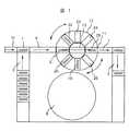
図1,図2は本発明の実施例を示したものである。
【0013】
試料を搭載したラック1はラック供給部であるAライン2上に架設される。分析が開始されるとラック1はAライン2上を搬送されB1ライン6に搬入される。さらにラック1はラックバッファ部12に格納される。
【0014】
図1の場合、ラックバッファ部12は円形状の例であり、ラック1はR1I部19に格納される。ラックバッファ部12は次のラック格納に備え、1ポジション回転しR2I部20がB1ライン6の延長上に停止する。ラック1は順次Aライン2から搬送されB1ライン6を経由しバッファ部12のR2I部20に格納される。以上の動作を繰り返し、ラックバッファ部12に複数のラック1が格納される。ラックの格納,搬送時にはラックストッパ14の上下によりラック停止位置が管理される。
【0015】
ラックバッファ部12のR1I部19,R2I部20,R3I部21,R4I部22にラック1が格納されると、ラックバッファ部12はR1I部19がB1ライン6の延長線上になるまで回転し、R1I部19に格納したラック1はラックバッファ中心部13を経由してR1O部23に搬送すると同時に、B1ライン6上を搬送されてきたラック1をR1I部19に格納する。
【0016】
ラックバッファ部12のラックバッファ中心部13を通過した部分はラック1に搭載された試料のサンプリング位置であり、この場合はR1O部23が該当する。サンプリングが終了したラック1はB2ライン7を経由しラック収納部であるCライン4に搬送される。R1I部19のラック搬出と同時に、ラックバッファ部12は回転し、R2I部20のラック1のR2O部24への搬送と、B1ライン6を搬送されてきたラック1のR2I部20への格納を行う。
【0017】
以上のようにラックバッファ部12は回転しながらラック1の格納と排出を繰り返す。このようなラックバッファ部12において、特定のポジションR3I部21を分析の優先権を持つラック専用とすることにより、先にライン上に搬送されたラックに優先してあとから搬送されたラックが分析を行う事ができる。
【0018】
つまり、分析に優先権を持つラック1が搬送された場合は、既にラックバッファ部12に搬送されているラック1に優先して、R3I部21がB1ライン6延長線上に回転し優先権を持つラック1のラックバッファ部12への格納を行う。格納されたラック1はR3I部21に格納されることなく、R3O部25に直接搬送され試料のサンプリングを開始する。
【0019】
さらに、ラックバッファ部12の近傍にラック投入スイッチ17を設け、ラックの直接投入を可能とすることにより、分析の優先権を持たせることができる。つまり、ラック投入スイッチ17を押すことにより特定のポジション、例えばR3I部21がラック投入口に回転・停止し、ラック架設後再びラック投入スイッチ17を押すことにより、ラックバッファ部12が回転、R3I部21に仮設したラック1をラックバッファ中心部13を経由して、R3O部25に搬送することにより、他のラックに優先して分析を行うことが可能となる。
【0020】
また、精度管理試料のように繰り返し分析を行うような試料の場合は、ラックバッファ部12内に任意の時間格納される専用位置を設け、試料のサンプリングが終了してもラック1を保持する。つまり、精度管理試料を搭載したラック1はR4I部22を通過しR4O部26に格納され、試料のサンプリングが行われる。サンプリングが終了してもB2ライン7へラック1の搬出を行わずに、ラックバッファ部12の回転動作を行い次のラック1の格納と排出動作に移行する。
【0021】
図2は、ラックバッファ部12が図1の円形状ではなく、ラック1を縦列格納するような形状を持つ実施例である。この例では、ラック収納部が4ポジションあり、P1部27,P2部28,P3部29,P4部30からなるラック格納トレイ31とそのスライド部15で構成される。B1ライン6を通過してきたラック1はP1部27に格納され、その後ラック収納トレイ31はスライドアーム16にて1ポジションスライドしP2部28がB1ライン6延長線上に移動し、次のラック1が収納される。
【0022】
このようにしてP4部30までラック1の収納を行った後、再びP1部27がB1ライン6延長線上までスライドし、ラック1に架設された試料のサンプリングを行う。サンプリングが終了したラック1はB2ライン7に搬出されると同時に、新たにラック1がP1部27に格納される。このようなラックバッファ部12において、特定のポジションP3部29を分析の優先権を持つラック専用とすることにより、先にライン上に搬送されたラック1に優先してあとから搬送されたラック1が分析を行う事ができる。
【0023】
つまり、分析に優先権を持つラック1が搬送された場合は、既にラックバッファ部12に搬送されているラック1に優先して、P3部29がB1ライン6延長線上にスライドし、試料のサンプリングを開始する。さらに、実施例1と同様にラック投入スイッチ17を設けることにより、投入したラック1に分析の優先権を持たせることができる。
【0024】
つまり、ラック投入スイッチ17を押すことにより特定のポジション、例えばP4部30がラックバッファ部12の末端にスライド・停止、ラック架設後再びラック投入スイッチ17を押すことにより、P4部30に架設したラックを優先的にB1ライン6延長線上にスライドし試料のサンプリングを行う。
【0025】
また、精度管理試料のように繰り返し分析を行うような試料の場合は、ラックバッファ部12内に任意の時間格納される専用位置を設け、試料のサンプリングが終了してもラック1を保持する。つまり、精度管理試料を搭載したラック1はP3部29に格納され、試料のサンプリングが行われる。サンプリングが終了してもB2ライン7へラック1の搬出を行わずに、ラックバッファ部12のスライド動作を行い次のラック1の格納と排出動作に移行する。
【0026】
このような実施例1,2において、ラックバッファ部12全体を低温に保冷する事により、一定時間保持される精度管理試料の濃縮防止、温度による成分の変性を防止し、信頼性の高い測定を行う事が可能となる。ラックバッファ部を保冷する事は、特に効果的である。
【0027】
【発明の効果】
以上説明したように、本発明のラックバッファ部をラック搬送ライン上に設ける事により、分析の優先権を持つ試料を搭載したラックを迅速に分析する事が可能となり、また、繰り返し同一試料を分析する場合でも繰り返し試料を投入する必要がなくなり、操作を簡便に行う事が可能となる。
【図面の簡単な説明】
【図1】本発明の実施例1の自動分析装置におけるラック搬送ラインの構成図である。
【図2】本発明の実施例2の自動分析装置におけるラック搬送ラインの構成図である。
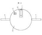
【図3】本発明の実施例1のラックバッファ部の構成図である。
【図4】本発明の実施例2のラックバッファ部の構成図である。
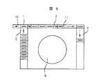
【図5】本発明の実施例1のラックバッファ部詳細の構成図である。
【図6】従来の自動分析装置ラック搬送ラインの構成図である。
【図7】従来の他の例を示す図である。
【符号の説明】
1…ラック、2…Aライン、3…Bライン、4…Cライン、5…Dライン、6…B1ライン、7…B2ライン、8…分析部、9…分析モジュール、10…至急検体割込み口、11…サンプリング位置、12…ラックバッファ部、13…ラックバッファ部中心、14…ラックストッパ、15…スライド部、16…スライドアーム、17…ラック投入スイッチ、18…ラック投入部、19…R1I部、20…R2I部、21…R3I部、22…R4I部、23…R1O部、24…R2O部、25…R3O部、26…R4O部、27…P1部、28…P2部、29…P3部、30…P4部、31…ラック収納トレイ。[0001]
BACKGROUND OF THE INVENTION
The present invention relates to a rack transport line (buffer unit) on which a sample transported in an automatic analyzer is mounted.
[0002]
[Prior art]
A conventional rack transport type automatic analyzer is configured such that racks are sequentially transported along a straight transport line.
[0003]
In the automatic analyzer shown in FIG. 6, the rack installed on the supply tray is sequentially transported along the A line, the B line, and the C line for analysis. In such a transport line configuration, when a sample that needs to be measured urgently is inserted, a rack is inserted into the sample interruption port immediately to interrupt the rack installed in the A line for preferential analysis. Can do. However, since a plurality of racks already transferred on the B line are arranged, there is a problem that measurement cannot be performed until the processing of these racks is completed.
[0004]
Further, when measuring a sample for performing accuracy management of an automatic analyzer, a sample with a management value set in advance is measured multiple times with an interval between normal samples. In this case, in the conventional rack transport, the rack for which the measurement has been completed is carried out to the C line. Therefore, every time the measurement needs to be performed, the rack on which the quality control sample is mounted must be installed on the A line. There was a problem of being.
[0005]
In the automatic analyzer shown in FIG. 7, when the rack installed on the A line passes through the B line, it is drawn into the D line only by the analysis module that needs to be analyzed, and the analysis is performed. An analysis module that does not require analysis is transported through the B line as it is, and is transported to an analysis module that requires analysis.
[0006]
In the analysis module that requires analysis, it is impossible to preferentially measure the rack that has been transported first on the D line. The measurement of the quality control sample is exactly the same as in FIG.
[0007]
[Problems to be solved by the invention]
In order to solve the above-described problems of the conventional example, the present invention is capable of preferentially analyzing a rack that is input prior to the rack transfer line, or a rack transfer line, or a rack input unit, It is an object of the present invention to provide a rack transport line that enables analysis without having to input a sample that needs to be repeatedly measured.
[0008]
[Means for Solving the Problems]
According to the present invention, a buffer section on a loop is provided in a transport line for transporting racks loaded with samples, and a plurality of racks stored in the buffer section can be analyzed in an arbitrary order. Alternatively, the rack can be directly placed in the buffer unit without going through the transport line, and measurement can be performed with priority.
[0009]
Further, a rack in which an arbitrary sample is mounted in the buffer unit is stored for an arbitrary time, and analysis can be performed at an arbitrary timing during that time.
[0010]
By doing so, it is possible to analyze a sample on a rack that has been input later in preference to a rack that has been input in advance.
[0011]
In addition, by storing a specific rack for an arbitrary time, it is possible to eliminate the trouble of loading each time even a sample that is analyzed in a specific time unit such as a quality control sample.
[0012]
DETAILED DESCRIPTION OF THE INVENTION
1 and 2 show an embodiment of the present invention.
[0013]
A
[0014]
In the case of FIG. 1, the
[0015]
When the
[0016]
The portion of the
[0017]
As described above, the
[0018]
In other words, when the
[0019]
Further, by providing a
[0020]
In the case of a sample that is repeatedly analyzed, such as a quality control sample, a dedicated position stored in the
[0021]
FIG. 2 shows an embodiment in which the
[0022]
After the
[0023]
In other words, when the
[0024]
In other words, a specific position, for example, the
[0025]
In the case of a sample that is repeatedly analyzed, such as a quality control sample, a dedicated position stored in the
[0026]
In Examples 1 and 2, the entire
[0027]
【The invention's effect】
As described above, by providing the rack buffer section of the present invention on the rack transport line, it is possible to quickly analyze a rack loaded with a sample having analysis priority and repeatedly analyze the same sample. In this case, it is not necessary to repeatedly input the sample, and the operation can be performed easily.
[Brief description of the drawings]
FIG. 1 is a configuration diagram of a rack transport line in an automatic analyzer according to a first embodiment of the present invention.
FIG. 2 is a configuration diagram of a rack transport line in an automatic analyzer according to a second embodiment of the present invention.
FIG. 3 is a configuration diagram of a rack buffer unit according to the first embodiment of the present invention.
FIG. 4 is a configuration diagram of a rack buffer unit according to a second embodiment of the present invention.
FIG. 5 is a detailed configuration diagram of a rack buffer unit according to the first embodiment of the present invention.
FIG. 6 is a configuration diagram of a conventional automatic analyzer rack transport line.
FIG. 7 is a diagram showing another conventional example.
[Explanation of symbols]
DESCRIPTION OF
Claims (4)
Translated fromJapanese該ラックバッファ部の中心がラック搬送ライン上に位置し、
該ラックバッファ部が回転することにより前記ラック搬送ラインで搬送されてきた検体ラックを該ラックバッファ部の任意のポジションに格納するとともに、
該ラックバッファ部に格納されていた検体ラックをラック搬送ラインに排出する機構を有するラックバッファ部を備えたことを特徴とする自動分析装置。A circular rack buffer unit having a plurality of positions for storing a sample rack in a radial direction,
The center of the rack buffer is located on the rack transport line,
While storing the sample rack that has been transported in the rack transport line by rotating the rack buffer unit at any position of the rack buffer unit,
An automatic analyzer comprising a rack buffer unit having a mechanism for discharging a sample rack stored in the rack buffer unit to a rack transport line.
前記ラックバッファ部に検体ラックを直接投入するためのラック投入部を備えたことを特徴とする自動分析装置。The automatic analyzer according to claim 1,
An automatic analyzer comprising a rack loading unit for directly loading a sample rack into the rack buffer unit.
前記ラックバッファ部に近傍に、前記ラックバッファ部の特定のポジションを前記ラック投入部に停止させるためのラック投入スイッチを設けたことを特徴とする自動分析装置。The automatic analyzer according to claim 1,
An automatic analyzer provided with a rack loading switch for stopping a specific position of the rack buffer section at the rack loading section in the vicinity of the rack buffer section.
前記ラックバッファ部に搭載された検体ラックを低温に保冷する機構を設けたことを特徴とする自動分析装置。The automatic analyzer according to any one of claims 1 to 3,
An automatic analyzer comprising a mechanism for keeping a sample rack mounted in the rack buffer unit at a low temperature.
Priority Applications (1)
| Application Number | Priority Date | Filing Date | Title |
|---|---|---|---|
| JP27461198AJP3668618B2 (en) | 1998-09-29 | 1998-09-29 | Automatic analyzer |
Applications Claiming Priority (1)
| Application Number | Priority Date | Filing Date | Title |
|---|---|---|---|
| JP27461198AJP3668618B2 (en) | 1998-09-29 | 1998-09-29 | Automatic analyzer |
Publications (2)
| Publication Number | Publication Date |
|---|---|
| JP2000105246A JP2000105246A (en) | 2000-04-11 |
| JP3668618B2true JP3668618B2 (en) | 2005-07-06 |
Family
ID=17544149
Family Applications (1)
| Application Number | Title | Priority Date | Filing Date |
|---|---|---|---|
| JP27461198AExpired - LifetimeJP3668618B2 (en) | 1998-09-29 | 1998-09-29 | Automatic analyzer |
Country Status (1)
| Country | Link |
|---|---|
| JP (1) | JP3668618B2 (en) |
Families Citing this family (79)
| Publication number | Priority date | Publication date | Assignee | Title |
|---|---|---|---|---|
| JP2004271265A (en)* | 2003-03-06 | 2004-09-30 | Hitachi High-Technologies Corp | Automatic analyzer |
| JP3931150B2 (en)* | 2003-03-19 | 2007-06-13 | 株式会社日立ハイテクノロジーズ | Automatic analyzer |
| DE102005042214A1 (en)* | 2005-09-05 | 2007-03-22 | Leica Microsystems Nussloch Gmbh | Receiving and transfer station for covered slides |
| DE102007008713B4 (en)* | 2007-02-20 | 2019-07-11 | Leica Biosystems Nussloch Gmbh | Tissue infiltration device |
| JP2008209338A (en)* | 2007-02-28 | 2008-09-11 | Hitachi High-Technologies Corp | Automatic analyzer |
| JP2008281453A (en)* | 2007-05-11 | 2008-11-20 | Hitachi High-Technologies Corp | Automatic analysis system |
| EP2330425B1 (en) | 2008-09-16 | 2020-04-08 | Hitachi High-Technologies Corporation | Sample processing system |
| JP5142976B2 (en)* | 2008-12-25 | 2013-02-13 | 株式会社日立ハイテクノロジーズ | Automatic analyzer |
| US8997589B2 (en)* | 2009-01-27 | 2015-04-07 | Hitachi High-Technologies Corporation | Automatic analysis apparatus and automatic analysis method |
| JP5093140B2 (en)* | 2009-02-09 | 2012-12-05 | 株式会社島津製作所 | Sample transport system |
| JP5452120B2 (en)* | 2009-07-29 | 2014-03-26 | 株式会社日立ハイテクノロジーズ | Automatic analyzer |
| DE102010028769A1 (en) | 2010-05-07 | 2011-11-10 | Pvt Probenverteiltechnik Gmbh | System for transporting containers between different stations and container carriers |
| WO2013002213A1 (en) | 2011-06-30 | 2013-01-03 | 株式会社日立ハイテクノロジーズ | Automatic analysis system |
| EP2589968A1 (en) | 2011-11-04 | 2013-05-08 | Roche Diagnostics GmbH | Laboratory sample distribution system, laboratory system and method of operating |
| EP2589966A1 (en) | 2011-11-04 | 2013-05-08 | Roche Diagnostics GmbH | Laboratory sample distribution system and corresponding method of operation |
| EP2589967A1 (en) | 2011-11-04 | 2013-05-08 | Roche Diagnostics GmbH | Laboratory sample distribution system and corresponding method of operation |
| JP6034051B2 (en)* | 2012-04-25 | 2016-11-30 | 東芝メディカルシステムズ株式会社 | Automatic analyzer |
| CN105229473B (en)* | 2013-06-17 | 2017-08-18 | 株式会社日立高新技术 | Automatic analysis device |
| JP2015135282A (en)* | 2014-01-17 | 2015-07-27 | 株式会社日立ハイテクノロジーズ | Automatic analyzer |
| DE102014202838B3 (en) | 2014-02-17 | 2014-11-06 | Roche Pvt Gmbh | Transport device, sample distribution system and laboratory automation system |
| DE102014202843B3 (en) | 2014-02-17 | 2014-11-06 | Roche Pvt Gmbh | Transport device, sample distribution system and laboratory automation system |
| EP2927168A1 (en) | 2014-03-31 | 2015-10-07 | Roche Diagniostics GmbH | Transport device, sample distribution system and laboratory automation system |
| EP2927625A1 (en) | 2014-03-31 | 2015-10-07 | Roche Diagniostics GmbH | Sample distribution system and laboratory automation system |
| EP2927163B1 (en) | 2014-03-31 | 2018-02-28 | Roche Diagnostics GmbH | Vertical conveyor, sample distribution system and laboratory automation system |
| EP2927167B1 (en) | 2014-03-31 | 2018-04-18 | F. Hoffmann-La Roche AG | Dispatch device, sample distribution system and laboratory automation system |
| EP2927695B1 (en) | 2014-03-31 | 2018-08-22 | Roche Diagniostics GmbH | Sample distribution system and laboratory automation system |
| EP2957914B1 (en) | 2014-06-17 | 2018-01-03 | Roche Diagnostics GmbH | Laboratory sample distribution system and laboratory automation system |
| EP2977766A1 (en) | 2014-07-24 | 2016-01-27 | Roche Diagniostics GmbH | Laboratory sample distribution system and laboratory automation system |
| EP3176587B1 (en) | 2014-07-31 | 2020-11-04 | Hitachi High-Tech Corporation | Automated analyzer |
| EP2995960B1 (en) | 2014-09-09 | 2020-07-15 | Roche Diagniostics GmbH | Laboratory sample distribution system and method for calibrating magnetic sensors |
| EP2995580A1 (en) | 2014-09-09 | 2016-03-16 | Roche Diagniostics GmbH | Laboratory sample distribution system and laboratory automation system |
| US9952242B2 (en) | 2014-09-12 | 2018-04-24 | Roche Diagnostics Operations, Inc. | Laboratory sample distribution system and laboratory automation system |
| EP2995958A1 (en) | 2014-09-15 | 2016-03-16 | Roche Diagniostics GmbH | Method of operating a laboratory sample distribution system, laboratory sample distribution system and laboratory automation system |
| EP3006943B1 (en) | 2014-10-07 | 2020-04-22 | Roche Diagniostics GmbH | Module for a laboratory sample distribution system, laboratory sample distribution system and laboratory automation system |
| EP3016116A1 (en) | 2014-11-03 | 2016-05-04 | Roche Diagniostics GmbH | Printed circuit board arrangement, coil for a laboratory sample distribution system, laboratory sample distribution system and laboratory automation system |
| EP3070479B1 (en) | 2015-03-16 | 2019-07-03 | Roche Diagniostics GmbH | Transport carrier, laboratory cargo distribution system and laboratory automation system |
| EP3073270B1 (en) | 2015-03-23 | 2019-05-29 | Roche Diagniostics GmbH | Laboratory sample distribution system and laboratory automation system |
| EP3095739A1 (en) | 2015-05-22 | 2016-11-23 | Roche Diagniostics GmbH | Method of operating a laboratory sample distribution system, laboratory sample distribution system and laboratory automation system |
| EP3096145B1 (en) | 2015-05-22 | 2019-09-04 | Roche Diagniostics GmbH | Method of operating a laboratory automation system and laboratory automation system |
| EP3096146A1 (en) | 2015-05-22 | 2016-11-23 | Roche Diagniostics GmbH | Method of operating a laboratory sample distribution system, laboratory sample distribution system and laboratory automation system |
| EP3112874A1 (en) | 2015-07-02 | 2017-01-04 | Roche Diagnostics GmbH | Storage module, method of operating a laboratory automation system and laboratory automation system |
| EP3121603A1 (en) | 2015-07-22 | 2017-01-25 | Roche Diagnostics GmbH | Sample container carrier, laboratory sample distribution system and laboratory automation system |
| EP3139175B1 (en) | 2015-09-01 | 2021-12-15 | Roche Diagnostics GmbH | Laboratory cargo distribution system, laboratory automation system and method of operating a laboratory cargo distribution system |
| EP3153866A1 (en) | 2015-10-06 | 2017-04-12 | Roche Diagnostics GmbH | Method of determining a handover position and laboratory automation system |
| EP3153867B1 (en) | 2015-10-06 | 2018-11-14 | Roche Diagniostics GmbH | Method of configuring a laboratory automation system, laboratory sample distribution system and laboratory automation system |
| EP3156352B1 (en) | 2015-10-13 | 2019-02-27 | Roche Diagniostics GmbH | Laboratory sample distribution system and laboratory automation system |
| EP3156353B1 (en) | 2015-10-14 | 2019-04-03 | Roche Diagniostics GmbH | Method of rotating a sample container carrier, laboratory sample distribution system and laboratory automation system |
| EP3211429A1 (en) | 2016-02-26 | 2017-08-30 | Roche Diagnostics GmbH | Transport device having a tiled driving surface |
| EP3211430A1 (en) | 2016-02-26 | 2017-08-30 | Roche Diagnostics GmbH | Transport device with base plate modules |
| EP3211428A1 (en) | 2016-02-26 | 2017-08-30 | Roche Diagnostics GmbH | Transport device unit for a laboratory sample distribution system |
| CN109196363A (en) | 2016-06-03 | 2019-01-11 | 豪夫迈·罗氏有限公司 | Laboratory sample distribution system and laboratory automation system |
| EP3255519B1 (en) | 2016-06-09 | 2019-02-20 | Roche Diagniostics GmbH | Laboratory sample distribution system and method of operating a laboratory sample distribution system |
| EP3260867A1 (en) | 2016-06-21 | 2017-12-27 | Roche Diagnostics GmbH | Method of setting a handover position and laboratory automation system |
| JP6752350B2 (en) | 2016-08-04 | 2020-09-09 | エフ.ホフマン−ラ ロシュ アーゲーF. Hoffmann−La Roche Aktiengesellschaft | Laboratory sample distribution system and laboratory automation system |
| CN106199029B (en)* | 2016-08-29 | 2018-10-23 | 爱威科技股份有限公司 | A kind of detection device and its method for supplementing carrier storage box |
| CN106706940B (en)* | 2016-11-15 | 2018-08-17 | 上海德孚生物医疗科技有限公司 | Biochemical analysis sample adding device |
| EP3330717B1 (en) | 2016-12-01 | 2022-04-06 | Roche Diagnostics GmbH | Laboratory sample distribution system and laboratory automation system |
| CN106771302B (en)* | 2016-12-19 | 2018-08-10 | 宁波美康盛德生物科技有限公司 | Biochemical Analyzer sample feeding propulsive mechanism |
| CN106771283B (en)* | 2016-12-19 | 2018-08-10 | 宁波美康盛德生物科技有限公司 | Biochemical Analyzer transport system |
| CN106841649B (en)* | 2016-12-19 | 2019-12-24 | 杭州美康盛德医学检验实验室有限公司 | Sample recovery system of biochemical analyzer |
| CN106771282B (en)* | 2016-12-19 | 2018-08-10 | 宁波美康盛德生物科技有限公司 | Biochemical Analyzer guideway transit system |
| EP3343232B1 (en) | 2016-12-29 | 2021-09-15 | Roche Diagnostics GmbH | Laboratory sample distribution system and laboratory automation system |
| EP3355065B1 (en) | 2017-01-31 | 2021-08-18 | Roche Diagnostics GmbH | Laboratory sample distribution system and laboratory automation system |
| EP3357842B1 (en) | 2017-02-03 | 2022-03-23 | Roche Diagnostics GmbH | Laboratory automation system |
| JP7075923B2 (en)* | 2017-02-22 | 2022-05-26 | 株式会社日立ハイテク | Automatic analyzer |
| CN108535501B (en)* | 2017-03-03 | 2021-08-06 | 爱威科技股份有限公司 | Sample frame transfer device |
| EP3410123B1 (en) | 2017-06-02 | 2023-09-20 | Roche Diagnostics GmbH | Method of operating a laboratory sample distribution system, laboratory sample distribution system and laboratory automation system |
| CN107290557B (en)* | 2017-06-30 | 2019-06-04 | 迈克医疗电子有限公司 | Sample analysis detection unit and sample analyser |
| EP3428653B1 (en) | 2017-07-13 | 2021-09-15 | Roche Diagnostics GmbH | Method of operating a laboratory sample distribution system, laboratory sample distribution system and laboratory automation system |
| EP3456415B1 (en) | 2017-09-13 | 2021-10-20 | Roche Diagnostics GmbH | Sample container carrier, laboratory sample distribution system and laboratory automation system |
| EP3457144B1 (en) | 2017-09-13 | 2021-10-20 | Roche Diagnostics GmbH | Sample container carrier, laboratory sample distribution system and laboratory automation system |
| EP3537159B1 (en) | 2018-03-07 | 2022-08-31 | Roche Diagnostics GmbH | Method of operating a laboratory sample distribution system, laboratory sample distribution system and laboratory automation system |
| EP3540443B1 (en) | 2018-03-16 | 2023-08-30 | Roche Diagnostics GmbH | Laboratory system, laboratory sample distribution system and laboratory automation system |
| WO2020152991A1 (en)* | 2019-01-25 | 2020-07-30 | 株式会社日立ハイテク | Automatic analysis system and specimen conveying method |
| EP3925911B1 (en) | 2020-06-19 | 2023-05-24 | Roche Diagnostics GmbH | Laboratory sample distribution system and corresponding method of operation |
| EP3940388B1 (en) | 2020-07-15 | 2024-04-10 | Roche Diagnostics GmbH | Laboratory sample distribution system and method for operating the same |
| EP4001923B1 (en) | 2020-11-23 | 2024-06-05 | Roche Diagnostics GmbH | Laboratory sample distribution system and laboratory automation system |
| US11747356B2 (en) | 2020-12-21 | 2023-09-05 | Roche Diagnostics Operations, Inc. | Support element for a modular transport plane, modular transport plane, and laboratory distribution system |
| CN113804904A (en)* | 2021-09-13 | 2021-12-17 | 广州蓝勃生物科技有限公司 | Sample reinspection control method and device, computer equipment and storage medium |
- 1998
- 1998-09-29JPJP27461198Apatent/JP3668618B2/ennot_activeExpired - Lifetime
Also Published As
| Publication number | Publication date |
|---|---|
| JP2000105246A (en) | 2000-04-11 |
Similar Documents
| Publication | Publication Date | Title |
|---|---|---|
| JP3668618B2 (en) | Automatic analyzer | |
| JP6093899B2 (en) | Automatic analyzer | |
| US9063104B2 (en) | Automatic analyzer | |
| JP5511025B2 (en) | Sample processing automation system | |
| EP2530471B1 (en) | Automatic analyzing device | |
| CN102305868A (en) | Automatic analyzer | |
| JPH10213586A (en) | Automatic analyzer | |
| JP2005274289A (en) | Blood specimen conveyance analysis system | |
| JPH01187461A (en) | Automatic chemical analyzer | |
| JP2018017606A (en) | Specimen automation system | |
| JPH0570113B2 (en) | ||
| JPH1090276A6 (en) | Specimen automation system | |
| JP2004028588A (en) | Automatic analyzer | |
| EP3940387B1 (en) | Automatic analysis device and automatic analysis method | |
| JP2011027655A (en) | Autoanalyzer | |
| JPH0833402B2 (en) | Automatic analyzer | |
| JP4491505B2 (en) | Automatic analyzer | |
| JP3655509B2 (en) | Sample transport system | |
| CN120077278A (en) | Container storage device | |
| JPWO2024053256A5 (en) | ||
| CN119678052A (en) | Container storage device, automatic analysis system, and sample container removal method | |
| JPH10253589A (en) | Electrophoretic system | |
| JPH08240595A (en) | Sample transport system | |
| JPH0434367A (en) | Chemical analyser |
Legal Events
| Date | Code | Title | Description |
|---|---|---|---|
| A977 | Report on retrieval | Free format text:JAPANESE INTERMEDIATE CODE: A971007 Effective date:20040716 | |
| A131 | Notification of reasons for refusal | Free format text:JAPANESE INTERMEDIATE CODE: A131 Effective date:20040803 | |
| A521 | Written amendment | Free format text:JAPANESE INTERMEDIATE CODE: A523 Effective date:20040924 | |
| TRDD | Decision of grant or rejection written | ||
| A01 | Written decision to grant a patent or to grant a registration (utility model) | Free format text:JAPANESE INTERMEDIATE CODE: A01 Effective date:20050405 | |
| A61 | First payment of annual fees (during grant procedure) | Free format text:JAPANESE INTERMEDIATE CODE: A61 Effective date:20050411 | |
| R150 | Certificate of patent or registration of utility model | Free format text:JAPANESE INTERMEDIATE CODE: R150 | |
| S533 | Written request for registration of change of name | Free format text:JAPANESE INTERMEDIATE CODE: R313533 | |
| R350 | Written notification of registration of transfer | Free format text:JAPANESE INTERMEDIATE CODE: R350 | |
| FPAY | Renewal fee payment (event date is renewal date of database) | Free format text:PAYMENT UNTIL: 20090415 Year of fee payment:4 | |
| FPAY | Renewal fee payment (event date is renewal date of database) | Free format text:PAYMENT UNTIL: 20090415 Year of fee payment:4 | |
| FPAY | Renewal fee payment (event date is renewal date of database) | Free format text:PAYMENT UNTIL: 20100415 Year of fee payment:5 | |
| FPAY | Renewal fee payment (event date is renewal date of database) | Free format text:PAYMENT UNTIL: 20110415 Year of fee payment:6 | |
| FPAY | Renewal fee payment (event date is renewal date of database) | Free format text:PAYMENT UNTIL: 20120415 Year of fee payment:7 | |
| FPAY | Renewal fee payment (event date is renewal date of database) | Free format text:PAYMENT UNTIL: 20120415 Year of fee payment:7 | |
| FPAY | Renewal fee payment (event date is renewal date of database) | Free format text:PAYMENT UNTIL: 20130415 Year of fee payment:8 | |
| FPAY | Renewal fee payment (event date is renewal date of database) | Free format text:PAYMENT UNTIL: 20140415 Year of fee payment:9 | |
| EXPY | Cancellation because of completion of term |