JP3666491B2 - Ink cartridge and recording apparatus - Google Patents
Ink cartridge and recording apparatusDownload PDFInfo
- Publication number
- JP3666491B2 JP3666491B2JP2003077849AJP2003077849AJP3666491B2JP 3666491 B2JP3666491 B2JP 3666491B2JP 2003077849 AJP2003077849 AJP 2003077849AJP 2003077849 AJP2003077849 AJP 2003077849AJP 3666491 B2JP3666491 B2JP 3666491B2
- Authority
- JP
- Japan
- Prior art keywords
- ink cartridge
- ink
- side wall
- connection terminal
- wall
- Prior art date
- Legal status (The legal status is an assumption and is not a legal conclusion. Google has not performed a legal analysis and makes no representation as to the accuracy of the status listed.)
- Expired - Fee Related
Links
- 238000003780insertionMethods0.000claimsdescription14
- 230000037431insertionEffects0.000claimsdescription14
- 238000005192partitionMethods0.000claimsdescription14
- 238000000638solvent extractionMethods0.000claimsdescription2
- 239000000976inkSubstances0.000description261
- 230000015654memoryEffects0.000description15
- 239000000758substrateSubstances0.000description10
- 238000012423maintenanceMethods0.000description6
- 230000002265preventionEffects0.000description4
- 238000004519manufacturing processMethods0.000description3
- 239000011148porous materialSubstances0.000description2
- 238000000926separation methodMethods0.000description2
- 230000001419dependent effectEffects0.000description1
- 238000001514detection methodMethods0.000description1
- 230000006870functionEffects0.000description1
- 230000005389magnetismEffects0.000description1
- 238000000034methodMethods0.000description1
Images


Classifications
- B—PERFORMING OPERATIONS; TRANSPORTING
- B41—PRINTING; LINING MACHINES; TYPEWRITERS; STAMPS
- B41J—TYPEWRITERS; SELECTIVE PRINTING MECHANISMS, i.e. MECHANISMS PRINTING OTHERWISE THAN FROM A FORME; CORRECTION OF TYPOGRAPHICAL ERRORS
- B41J2/00—Typewriters or selective printing mechanisms characterised by the printing or marking process for which they are designed
- B41J2/005—Typewriters or selective printing mechanisms characterised by the printing or marking process for which they are designed characterised by bringing liquid or particles selectively into contact with a printing material
- B41J2/01—Ink jet
- B41J2/17—Ink jet characterised by ink handling
- B41J2/175—Ink supply systems ; Circuit parts therefor
- B41J2/17503—Ink cartridges
- B41J2/17513—Inner structure
- B—PERFORMING OPERATIONS; TRANSPORTING
- B41—PRINTING; LINING MACHINES; TYPEWRITERS; STAMPS
- B41J—TYPEWRITERS; SELECTIVE PRINTING MECHANISMS, i.e. MECHANISMS PRINTING OTHERWISE THAN FROM A FORME; CORRECTION OF TYPOGRAPHICAL ERRORS
- B41J2/00—Typewriters or selective printing mechanisms characterised by the printing or marking process for which they are designed
- B41J2/005—Typewriters or selective printing mechanisms characterised by the printing or marking process for which they are designed characterised by bringing liquid or particles selectively into contact with a printing material
- B41J2/01—Ink jet
- B41J2/17—Ink jet characterised by ink handling
- B41J2/175—Ink supply systems ; Circuit parts therefor
- B41J2/17503—Ink cartridges
- B41J2/1752—Mounting within the printer
- B—PERFORMING OPERATIONS; TRANSPORTING
- B41—PRINTING; LINING MACHINES; TYPEWRITERS; STAMPS
- B41J—TYPEWRITERS; SELECTIVE PRINTING MECHANISMS, i.e. MECHANISMS PRINTING OTHERWISE THAN FROM A FORME; CORRECTION OF TYPOGRAPHICAL ERRORS
- B41J2/00—Typewriters or selective printing mechanisms characterised by the printing or marking process for which they are designed
- B41J2/005—Typewriters or selective printing mechanisms characterised by the printing or marking process for which they are designed characterised by bringing liquid or particles selectively into contact with a printing material
- B41J2/01—Ink jet
- B41J2/17—Ink jet characterised by ink handling
- B41J2/175—Ink supply systems ; Circuit parts therefor
- B41J2/17503—Ink cartridges
- B41J2/17526—Electrical contacts to the cartridge
- B—PERFORMING OPERATIONS; TRANSPORTING
- B41—PRINTING; LINING MACHINES; TYPEWRITERS; STAMPS
- B41J—TYPEWRITERS; SELECTIVE PRINTING MECHANISMS, i.e. MECHANISMS PRINTING OTHERWISE THAN FROM A FORME; CORRECTION OF TYPOGRAPHICAL ERRORS
- B41J2/00—Typewriters or selective printing mechanisms characterised by the printing or marking process for which they are designed
- B41J2/005—Typewriters or selective printing mechanisms characterised by the printing or marking process for which they are designed characterised by bringing liquid or particles selectively into contact with a printing material
- B41J2/01—Ink jet
- B41J2/17—Ink jet characterised by ink handling
- B41J2/175—Ink supply systems ; Circuit parts therefor
- B41J2/17503—Ink cartridges
- B41J2/17543—Cartridge presence detection or type identification
- B41J2/17546—Cartridge presence detection or type identification electronically
Landscapes
- Ink Jet (AREA)
Description
Translated fromJapanese【0001】
【発明の属する技術分野】
本発明は、記録装置にインクを供給するインクカートリッジ、およびインクカートリッジが着脱自在なキャリッジとこのキャリッジに搭載された記録ヘッドとを備えた記録装置に関する。特に本発明は、記録装置に正確に装着されることによりインクを記録装置に供給するインクカートリッジに関する。
【0002】
【従来の技術】
一般に、記録装置の1つであるインクジェット式プリンタは、給紙トレイにセットされた用紙等の印字媒体を給紙機構により1枚ずつ給紙し、用紙搬送手段により副走査方向に間欠的に所定量ずつ送りつつ、主走査方向に往復移動するキャリッジに搭載された記録へッドによりインク滴を印字媒体に射出して文字や画像等を記録するようになっている。通常、フルカラーのインクジェット式プリンタのキャリッジには、ブラックインクを収容しているインクカートリッジと、イエロー、シアン、マゼンタ等の各色のインクを収容するインクカートリッジとが独立的に装着されている。
【0003】
キャリッジは、記録ヘッドのメンテナンス効率を高めるために、記録ヘッドを搭載したヘッド搭載部と、インクカートリッジを装着するカートリッジ装着部とに分離可能に構成されている。そして、インクカートリッジには、製造年月日、型番、インク残量等のインク等に関する情報を記憶しているメモリが装着されており、このメモリとコネクタを介して接続されるとともに記録ヘッドに接続される回路基板が、キャリッジのヘッド搭載部に配設されている。そして、記録装置との間で該インク等に関する情報を送受信するように設計されている。この情報記憶するメモリの一例は、接続端子が外部に露出した接続端子部と、この接続端子と電気的に接続されるメモリ部とを有する接触式の情報記憶部である。この接続端子は、記録装置側の接続端子と接触することによって電気的に接続する。メモリ部はインク等に関する情報を記憶する(例えば、特許文献1参照)。
【0004】
【特許文献1】
国際公開第99/59823号パンフレット
【0005】
【発明が解決しようとする課題】
上述した従来のインクジェット式プリンタでは、インクカートリッジの情報記憶部の接続端子部は、記録装置側の接続端子と確実に接触していないと、情報の送受信が正しくできない。特に複数の小面積の接続端子領域が近接して配列されている場合には、記録装置側の接続端子との位置合わせは非常に正確である必要がある。
【0006】
また、従来のインクジェット式プリンタは回路基板がキャリッジのヘッド搭載部に配設されているため、記録ヘッドを装置本体から取り外してメンテナンス処理を行う際に破損するおそれがある。
【0007】
本発明の他の目的は、インクカートリッジの情報記憶部の接続端子部と、記録装置側の接続端子とが確実に接触することができるインクカートリッジを提供することである。
【0008】
さらに、本発明の他の目的は、インクカートリッジの接続端子部および記録装置側の接続端子の装着位置に自由度を有するインクカートリッジを提供することである。
【0009】
また、本発明の他の目的は、記録ヘッドのメンテナンス処理の際に、インクカートリッジのインク情報を読み書きする素子が実装された基板を保護することができる記録装置を提供することにある。
【0010】
【課題を解決するための手段】
これらの目的は特許請求の範囲における独立項に記載の特徴の組み合わせにより達成される。また従属項は本発明の更なる有利な具体例を規定する。
【0011】
即ち、本発明の第1の形態によると、記録装置に装着されることにより、記録ヘッドと連通したインク供給針を介して内部のインクを前記記録装置に供給するインクカートリッジであって、底壁と、該底壁と隣接する第1の側壁と、該第1の側壁と対向する第2の側壁を有すると共に、内部にインクを収容するインクカートリッジ本体と、前記底壁の前記第1の側壁に偏した位置に設けられ、前記インク供給針が挿入可能に形成されたインク供給孔を有するインク供給部と、前記インクカートリッジ本体に配設された接続端子部を有する情報記憶部と、前記記録装置に形成された位置決め溝と係合可能に形成された突出部とを備え、前記接続端子部及び前記突出部は、前記第2の側壁側に配設されていることを特徴とする。
【0012】
前記インクカートリッジにおいて、前記突出部は、前記底壁方向に延出して形成されていてもよい。
【0013】
前記インクカートリッジにおいて、前記インクカートリッジ本体は、前記底壁と対向する上壁を有し、前記接続端子部および前記突出部よりも前記上壁側に、凸部を備えてもよい。
【0014】
前記インクカートリッジにおいて、前記凸部は、前記突出部よりも外方に突出するよう形成されていると共に、前記凸部は、面位置が前記位置決めリブよりも突出した前記第1の壁と略平行な面を有してもよい。
【0015】
前記インクカートリッジにおいて、前記突出部は、前記接続端子部における前記記録装置に装着する方向に直行する方向の幅の外に位置してもよい。
【0016】
前記インクカートリッジにおいて、前記接続端子部は、前記第2の側壁側の、前記底壁および前記第2の側壁の両壁と隣接する第3の側壁に偏して配設されていてもよい。
【0017】
前記インクカートリッジにおいて、前記第3の側壁と対向する第4の側壁に逆挿防止リブをさらに備えてもよい。
【0018】
前記インクカートリッジにおいて、前記突出部は、前記第3の側壁と対向する第4の側壁に偏して形成されていてもよい。
【0019】
前記インクカートリッジにおいて、前記容器本体内部を仕切壁によって区画して形成された複数のインク室を備えてもよい。
【0020】
前記インクカートリッジが装着される記録装置において、記録ヘッドを搭載したヘッド搭載部と、前記インクカートリッジを装着するカートリッジ装着部とを有するキャリッジを備え、前記インクカートリッジの接続端子部と接続することにより、前記情報記憶部に対して情報を読み書きする素子が実装された基板が、前記カートリッジ装着部に配設されていてもよい。
【0021】
前記インクカートリッジの接続端子部と接続する素子が実装された基板が、前記カートリッジ装着部の前方側内側壁に配設されていてもよい。
【0022】
なお上記の発明の概要は、本発明の必要な特徴の全てを列挙したものではなく、これらの特徴群のサブコンビネーションも又発明となりうる。
【0023】
【発明の実施の形態】
以下、図面に基づいて本発明の実施の形態について詳細に説明する。以下の実施形態はクレームにかかる発明を限定するものではなく、又実施形態の中で説明されている特徴の組み合わせの全てが発明の解決手段に必須であるとは限らない。
【0024】
(記憶素子保護機構)
図1は、本発明の実施の形態に係る記録装置の1つであるインクジェット式プリンタの外部構成の全体を斜め前方から見た斜視図である。このインクジェット式プリンタ100は、全体が幅方向に長く延びる直方体状の上部ハウジング101と下部ハウジング102を備えている。上部ハウジング101と下部ハウジング102は、スナップフィットにより締結されている。
【0025】
上部ハウジング101の後方側には、給紙口103が形成されている。この給紙口103には、給紙される用紙が積層載置される給紙トレイ110及びこの給紙トレイ110の一端側に揃えられる給紙ガイド111が配設されている。給紙トレイ110は、給紙ガイド111から斜め上後方へ突き出るように配設されており、用紙を傾斜した状態で保持するようになっている。
【0026】
上部ハウジング101の前方側には、排紙口104が形成されている。この排紙口104には、排紙される用紙が積層載置される排紙スタッカ120が配設されている。排紙スタッカ120は、不使用時は排紙口104から下部ハウジング102の裏面側に収納可能に、使用時は排紙口104から斜め上前方へ引出可能に配設されており、用紙を傾斜した状態で受けるようになっている。
【0027】
さらに、排紙口104には、排紙スタッカ120が引き出された時に、排紙スタッカ120の非排紙側端部を幅方向に沿って保持するスタッカ保持部121が設けられている。なお、図1では、排紙スタッカ120は、下部ハウジング102の裏面側に収納された状態が示されている。
【0028】
上部ハウジング101の上部から前面にかけて窓部105が形成されている。この窓部105は、透明もしくは半透明な湾曲した開閉自在なカバー106によって覆われている。このカバー106を開放することにより、インクカートリッジの交換作業や内部機構のメンテナンス作業等を容易に行うことができる。また、上部ハウジング101の左後方側には、押しボタン式のパワー系のスイッチ131と操作系のスイッチ132が配設されている。
【0029】
図2は、図1のインクジェット式プリンタ100の上部ハウジング101を取り外したときの内部構成の全体を斜め前方から見た斜視図、図3はその主要部の断面側面図である。下部ハウジング102上には、プリンタコントローラを構成する図2に示すメイン基板130が縦置きに配置されていると共に、プリントエンジンを構成する図2に示す記録手段140と、図3に示す用紙の供給手段150及び搬送手段160等が配設されている。
【0030】
メイン基板130には、図示しないCPU、ROM、RAM、ASIC等の制御素子や記憶素子、及びその他の各種回路素子が装着されており、その上端には、上述したパワー系のスイッチ131や操作系のスイッチ132が押された時にそれぞれ発光することによりユーザがスイッチONを確認し得るように配置された発光ダイオード133、134が突設されている。
【0031】
記録手段140は、キャリッジ141、記録ヘッド142、キャリッジモータ143、タイミングベルト144、吸引ポンプ145及び検出装置等を備えている。搬送手段160により搬送される用紙は、キャリッジモータ143とタイミングベルト144により走査されるキャリッジ141に搭載された記録ヘッド142により記録されるようになっている。この記録ヘッド142は、フルカラー印刷が可能なように、キャリッジ141内に収納された例えばイエロー、マゼンタ、シアン、ブラックの計4色のインクカートリッジ146から各色インクが供給されるようになっている。
【0032】
供給手段150は、給紙トレイ110、給紙ガイド111、給紙ローラ151、ホッパ152、分離パッド153等を備えている。給紙トレイ110に積層載置され給紙ガイド111により揃えられた用紙Pは、給紙ローラ151の回転に伴うホッパ152の上昇により分離パッド153で給紙ローラ151に押付けられ、最上位の用紙Pから1枚ずつ分離されて搬送手段160へ給送されるようになっている。
【0033】
搬送手段160は、紙送りローラ161と従動ローラ162、排紙ローラ163とギザローラ164、紙送りモータ165、排紙スタッカ120等を備えている。供給手段150から供給される用紙Pは、紙送りモータ165により駆動されている紙送りローラ161と従動ローラ162に挟持されて記録手段140へ搬送され、さらに紙送りモータ165により駆動されている排紙ローラ163とギザローラ164に挟持されて排紙スタッカ120へ搬送されるようになっている。
【0034】
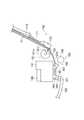
図4は上記キャリッジ141を示す側面図、図5はその平面図、図6はその一部を取り除いた状態を示す斜視図である。このキャリッジ141は、本体部141aとカバー部141b(図4、5参照)を備えている。キャリッジ141の本体部141aの底面には、記録ヘッド142(図4、5参照)が搭載され、キャリッジ141の本体部141aの内部には、ブラックインクを貯留しているインクカートリッジ146B(図6参照)と、イエロー、シアン、マゼンタ等の各色のインクを貯留するインクカートリッジ146C(図6参照)が装着される。
【0035】
また、キャリッジ141の本体部141aの背面両側部には、キャリッジ案内部41(図4、5参照)が所定間隔をあけて一体的に形成されている。そして、用紙の搬送方向と直交する方向でかつ垂直方向に配設されたメインフレーム107(図4参照)には、上記キャリッジ案内部41が抱持して摺動する案内部材43(図4参照)が形成されている。この案内部材43は、メインフレーム107と同様に配設され、先端の断面がZ形状となるように折り曲げられている。そして、キャリッジ案内部41は、案内部材43の折り曲げ部分のうち、水平部分43aを挟持する一対の突起41a、41bと、垂直部分43bを挟持する一対の突起41c、41dが形成されている。さらに、キャリッジ141の本体部141aの前部側下面中央部には、摺動部42(図4参照)が一体的に形成されている。そして、用紙の搬送方向と直交する方向でかつ水平方向に配設された排紙フレーム108には、上記摺動部42が摺動する案内部材44(図4参照)が形成されている。
【0036】
このキャリッジ141も、従来と同様に記録ヘッド142のメンテナンス効率を高めるために、記録ヘッド142を搭載したヘッド搭載部141Aと、インクカートリッジ146B、146Cを装着するカートリッジ装着部141Bとに分離可能に構成されている。そして、カートリッジ装着部141Bの前方側内側壁には、コネクタ147b、147c(図6参照)を含む回路基板148(図6参照)が配設されている。
【0037】
この回路基板148は、インクカートリッジ146B、146Cの前面側に装着されている、インクの製造年月日、型番、インク残量等のインクに関する情報を記憶しているコネクタを含むメモリ149b、149c(図6参照)と、コネクタ147b、147cを介して接続される。なお、記録ヘッド142に接続される基板は、回路基板148と分離されてヘッド搭載部141Aの後方側内側壁に配設されている。
【0038】
このような構成によれば、記録ヘッド142はヘッド搭載部141Aに搭載されており、回路基板148はカートリッジ装着部141Bに配設されているので、記録ヘッド142のメンテナンス処理の際には記録ヘッド142と回路基板148を離間させることができ、回路基板148を保護することができる。
【0039】
なお、インクカートリッジ146B、146Cの前面側には、コネクタを含むメモリ149b、149cと回路基板148のコネクタ147b、147cとを接続する際の位置決め用リブ146Ba、146Caが形成されている。すなわち、この位置決め用リブ146Ba、146Caは、インクカートリッジ146B、146Cがキャリッジ141のカートリッジ装着部141Bに装着される際に、カートリッジ装着部141Bの前面側に設けられている溝141Ba、141Bbに填り込むことにより、コネクタを含むメモリ149b、149cと回路基板148のコネクタ147b、147cとを位置決めするようになっている。
【0040】
また、インクカートリッジ146B、146Cの側面側には、他の形式のキャリッジに誤装着しないように誤装着防止用リブ146Bb、146Cbが形成されている。すなわち、この誤装着防止用リブ146Bb、146Cbは、インクカートリッジ146B、146Cがキャリッジ141のカートリッジ装着部141Bに装着される際に、カートリッジ装着部141Bの側面側に設けられている溝141Bc、141Bdに填り込み、カバー部141bを正常に閉じることができるようになっているが、他の形式のキャリッジのときは衝突して装着できないため、そのカバー部を正常に閉じることができようにして誤装着を防止するようになっている。
【0041】
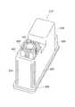
図7は本願の実施形態にかかるインクカートリッジの一例の上面斜視図である。図8は、このインクカートリッジの底面斜視図である。インクカートリッジ210は、インクカートリッジ本体220と、インク供給部240と、情報記憶部260と、位置決め部280とを備える。
【0042】
インクカートリッジ本体220は、その内部にインクを収容する。このインクカートリッジ本体220には、例えば黒のインクが収容される。インクカートリッジ本体220の一例は、単一の略直方体形状の容器本体内に、インクを含有したインク含浸部材である多孔質材(図示せず)が充填されている。しかし本発明はこれに限られず、他の例として中空の容器本体にインクを直接収容し、インク供給部内に設けられた弁などの開閉手段により選択的にインクを記録装置に供給するものであってもよい。
【0043】
インク供給部240は、インクカートリッジ本体220の底面222に設けられたインク供給孔242を有する。インク供給孔242は、インクカートリッジ本体220の底面222の、該底面222と交差する第1の側壁224側に偏する位置に設けられている。なお、ここで底面および側壁とは、インク供給部240が設けられた面を底面と定義して各々の位置関係を表すものであって、インクカートリッジ210の使用状態において必ずしも底面が下向きに位置することを表すものではない。
【0044】
情報記憶部260は、インクカートリッジの種類、インクカートリッジが保持するインクの種類、色、インクの現存量等、インクに関する情報を記憶する記憶装置を有している。情報記憶部260の一例は、接触式のICチップである。接触式のICチップは、基板と、基板の表側に露出された複数の接触子を含む接続端子部と、基板の裏側に設けられたメモリとを有し、接触子に外部から触されて電気的に接続されることによりメモリの情報データが読み出されたり、書き換えられたりする。
【0045】
本実施形態において、情報記憶部260は接触式であり、外部に露出された7つの接触子を含む接続端子部262を有する。接続端子部262は、インクカートリッジ本体220の底面222と交差しかつ第1側壁224と対向する第2側壁226に設けられる。ただし、接触式の接続端子部における接触子は7つに限られない。また、接続端子部262のみが第2側壁226に設けられ、一方情報記憶部260のメモリを他の側壁等インクカートリッジ本体220の適切な位置に配設し、接続端子部262と情報記憶部のメモリとの間を、例えばフレキシブルプリントサーキット(FPC)で引き回して電気的に接続させる構造であってもよい。さらに、接触式に限られず、磁気または光学を利用した非接触式の情報記憶部であってもよい。
【0046】
図9(a)は、本実施形態のインクカートリッジ210を第2側壁226の側からみた平面図である。図9(b)は、このインクカートリッジ210を第3側壁227からみた平面図である。第2側壁226上には、インクカートリッジ210が記録装置に適切な位置に装着される機能を有する位置決め部280が設けられている。位置決め部280は、第2側壁226から突出し、かつ底面222の方向に延びる位置決めリブ282を有する。図9(a)に見られるように、位置決めリブ282は、接続端子部の幅W1の範囲外に位置する。すなわち、位置決めリブ282の中央線(一点鎖線)は、接続端子部の幅W1(二本の鎖線の間)の外にある。
【0047】
インクカートリッジ210は、さらに情報記憶部260の接続端子部262および位置決めリブ282よりも上面側に設けられた凸部290を備える。凸部290は、その面位置が位置決めリブ282よりも突出し、第2側壁と略平行な面292を有する。すなわち、図9(b)において、凸部290の面292の面位置(破線)は、位置決めリブ282(一点鎖線)および接続端子部262(2点鎖線)よりも突出している(図中の左側)。これにより、使用者がインクカートリッジ210を取り扱う場合に、凸部290が外部と接触するので、接続端子部262および位置決めリブ282を外部からの衝撃等から保護することができる。特に使用者がインクカートリッジ210を誤って床に落としてしまったとしても、接続端子部262が床に接触しないのでダメージを受けることはない。
【0048】
また、図9(a)に示されるように、接続端子部262の中心、即ち図9(a)の実施例では上列中央の接続端子の縦方向の中心線は、インク供給孔の中心軸(2点鎖線)からずれた位置に配置されている。接続端子部262は、第2側壁226上の、底面222および第2側壁の両方と交差する第3側壁227の近傍に偏して配される。なお、インクカートリッジ210には、接続端子部262が偏する第3側壁227と対向する第4側壁228に設けられた逆挿防止リブ229をさらに備えている。
【0049】
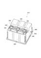
図10は、本願の実施形態にかかるインクカートリッジの他の一例の上面斜視図であり、図11はこのインクカートリッジの底面斜視図である。インクカートリッジ310は、インクカートリッジ本体320と、インク供給部340と、情報記憶部360と、位置決め部380とを備えている。
【0050】
図12は、インクカートリッジ310の分解斜視図である。インクカートリッジ本体320は、その内部に設けられる仕切壁333、335を有する。インクカートリッジ本体320は、さらに、これらの仕切壁333、335により仕切られて、それぞれ異なるインクを収容する複数のインク室332、334、336とを有する。図12に示す実施形態のインクカートリッジ本体320は、外壁331と仕切壁333とで作られるインク室332と、仕切壁333と仕切壁335とで作られるインク室334と、仕切壁335と外壁337とで作られるインク室336との、3個のインク室を有する。これらのインク室には、例えば、インク室332にはシアンのインクが、インク室334にはマゼンタのインクが、インク室336にはイエローのインクが収容される。さらに、インクカートリッジ本体320は、底面322と略平行な共通蓋部339を有する。なお、図12は、仕切壁とインク室を説明するための斜視図であり、インクを保持する多孔質材などその他の構成は省略されている。
【0051】
インク供給部340は、複数のインク室332、334,336のそれぞれに対応してインクカートリッジ本体310の底面322に設けられ、インクカートリッジ本体320の底面322に交差する第1側壁324に偏して位置するインク供給孔342、344、346を有する。
【0052】
情報記憶部360は、接続端子部362を有する。接続端子部362は、インクカートリッジ本体320の底面322と交差しかつ第1側壁324と対向する第2側壁326において、仕切壁333に対応する位置364に設けられる。この情報記憶部360は、図7に示すインクカートリッジ210の情報記憶部260と同様の構成および作用を有するので、これらの説明を省略する。
【0053】
図13(a)は、本実施形態のインクカートリッジ310を第2側壁326の側からみた平面図である。図13(b)は、このインクカートリッジ310を第4側壁328からみた平面図である。
【0054】
図13(a)に示されるように、接続端子部362の中心は、インク供給孔の中心軸(2点鎖線)からずれた位置に配される。接続端子部362は、第2側壁326上の、底面322および第2側壁326の両壁と交差する第3側壁327の近傍に偏して配される。接続端子部362は、上述のように、第3側壁327により近い仕切壁333に対応する位置に配されている。仕切壁333に対応する位置の中心線(一点鎖線)が、情報記憶部360の接続端子部362の幅W2(二本の破線の間)の中に位置するように構成されている。さらに、この実施形態にかかるインクカートリッジ310にあっては、接続端子部362の中心線が、仕切壁333に対応する位置の中心線と略一致する。
【0055】
インクカートリッジ310の位置決め部380は、インクカートリッジ210と同様に、第2側壁326から底面322に向かう方向に延出する位置決めリブ382を有する。位置決めリブ382は、接続端子部の幅W2の外に位置する。すなわち、図13(a)において、位置決めリブ382の中央線(一点鎖線)は、接続端子部の幅W2の範囲の外にある。
【0056】
インクカートリッジ310は、前実施例によるインクカートリッジ210と同様に、情報記憶部360の接続端子部362および位置決めリブ382よりも上面側に設けられる凸部390をさらに備える。凸部390は、その面位置が位置決めリブ382よりも突出し、第2側壁326と略平行な面392を有する。すなわち、図13(b)において、凸部390の面392の面位置(破線)は、位置決めリブ382(一点鎖線)および接続端子部362(2点鎖線)よりも突出している(図中の左側方向へ)。
【0057】
インクカートリッジ310には、接続端子部362が偏する第3側壁327と対向する第4側壁328上に設けられた逆挿防止リブ329をさらに備えている。
【0058】
図14は、2つインクカートリッジが装着される記録装置のキャリッジの上面斜視図である。キャリッジ400は、上述の黒のインクを収容したインクカートリッジ210を収容する第1収容部410と、シアン、マゼンタおよびイエローのインクを収容したインクカートリッジ310を収容する第2収容部450とを有する。
【0059】
第1収容室410には、インクカートリッジ210を収容したときの情報記憶部260の接続端子部262に対応する位置に、接続端子部420が設けられる。さらに、第1収容室410は、接続端子部420と同じ側壁であって、接続端子部420よりも第2収容室450から離れた位置に、インクカートリッジ210の位置決めリブ282が係合する位置決め溝430を有する。さらに、第1収容室410は、第2収容部450と対向する側壁に、インクカートリッジ210の逆挿防止リブ282が係合する切欠部440を有する。
【0060】
また、図14の方向からは見えないが、第1収容室410の底面において、インクカートリッジ210のインク供給部240と対応する位置に、インク供給針部412が設けられる。インク供給針部412は、中空のインク供給針と、インク供給針においてキャリッジ400の底面側に端面とを有する。
【0061】
第1収容部410と同様に、第2収容室450には、インクカートリッジ310を収容したときの情報記憶部360の接続端子部362に対応する位置に、接続端子部460が設けられる。さらに、第2収容室450は、接続端子部460と同じ側壁であって、接続端子部460よりも第1収容室410から離れた位置に、インクカートリッジ310の位置決めリブ382が係合する位置決め溝470を有する。さらに、第2収容室450は、第1収容部410と対向する側壁に、インクカートリッジ310の逆挿防止リブ382が係合する切欠部480を有する。さらに、第2収容室410の底面において、第1収容室と同様に、インク供給針部452が設けられる。インク供給針部452の構成は、第1収容部410におけるインク供給針部452と同様であるが、インクカートリッジ310が3つのインク供給孔342、344、346を有していることに対応して、3つのインク供給針を有する。
【0062】
図15は、キャリッジに装着される2つのインクカートリッジの位置関係を示す斜視図である。図15に示すように、インクカートリッジ210およびインクカートリッジ310が隣り合うようにしてキャリッジ400上に装着される。この場合に、インクカートリッジ210の第3側面227とインクカートリッジ310の第3側面327とが向き合っている。
【0063】
上述のように、インクカートリッジ210の接続端子部262は、第3側面227に偏して位置しており、かつ、インクカートリッジ310の接続端子部362は、第3側面327に偏して位置している。すなわち、インクカートリッジ210の接続端子部262とインクカートリッジ310の接続端子部362とが近接するように配置され、キャリッジ上に装着されている。よって、図14で示すキャリッジ400のように、第1収容部410の接続端子420と第2収容部450の接続端子460とを近接して配することができ、FPCなどの配線を不要に長く引き回す必要がない。
【0064】
さらに、上述のように、インクカートリッジ210の逆挿防止リブ229は、第3側面227に対向する第4側面228に配され、かつ、インクカートリッジ310の逆挿防止リブ329は、第3側面327に対向する第4側面328に配される。すなわち、インクカートリッジ210の逆挿防止リブ229とインクカートリッジ310の逆挿防止リブ329とは向かい合わせの位置にはない。よって、キャリッジ400は、隣り合う第3側面227、327同士を非常に近い距離で装着することができ、キャリッジ400全体の大きさを小さくすることができる。
【0065】
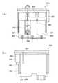
図16(a)および図16(b)は、インクカートリッジがキャリッジに装着される動作を示す部分断面図である。図16(a)および図16(b)は、位置決め溝470を含む平面でのキャリッジ400の第2収容部450の断面図を示す。また、インクカートリッジ310がキャリッジ400の第2収容部450に装着される例で説明するが、インクカートリッジ210がキャリッジ400の第1収容部410に装着される場合も同様である。
【0066】
図16(a)に示すように、インクカートリッジ310がキャリッジ400の第2収容部450に対して、正規の方向に配される。ここで正規の方向とは、インクカートリッジ310のインク供給部340を第2収容部450のインク供給針部452に対向させるとともに、インクカートリッジ310の接続端子部362を収容部450の接続端子部460に対向させる方向をいう。正規の方向に配したインクカートリッジ310がキャリッジ400の第2収容部450に挿入される。
【0067】
図16(b)に示すように、図16(a)の状態からインクカートリッジ310が挿入されると、インクカートリッジ310の位置決めリブ382は、第2収容部450の位置決め溝470に案内される。また、インクカートリッジ310の逆挿防止リブ329が、第2収容部450の切欠き部480に受け入れられて係合する。
【0068】
さらにインクカートリッジ310が挿入されると、第2収容部450のインク供給針部452がインクカートリッジ310のインク供給部340の内部に侵入する。インクカートリッジ310のインク供給部340の端面が、第2収容部450のインク供給針部452の端面に当接して、挿入が終了する。これにより、インクカートリッジ310は、インク供給針部452を通じて、インクを記録装置に供給する。
【0069】
図17(a)および図17(b)は、インクカートリッジがキャリッジに装着される動作を示す別の部分断面図である。図17(a)および図17(b)は、位置決め溝470を含まない平面でのキャリッジ400の第2収容部450の断面図を示す。
【0070】
図17(a)は図16(a)に対応し、インクカートリッジ310がキャリッジ400の第2収容部450に対して、正規の方向に配される状態を示す。図17(b)は図16(b)に対応し、インクカートリッジ310がキャリッジ400の第2収容部450に装着された状態を示す。
【0071】
図17(b)に示すように、インクカートリッジ310のインク供給部340の端面が第2収容部450のインク供給針部452の端面に当接したとき、インクカートリッジ310の凸部290の下端面が第2収容部450の面472に当接する。
【0072】
インクカートリッジ310は、インク供給針452がインク供給部340に進入することにより位置決めされるとともに、位置決めリブ382が位置決め溝470に係合することによっても位置決めされる。よって、位置決めリブ382により同じ第2側面326で位置決めされるので、インクカートリッジ310の接続端子部362は、インク供給部340から離れた位置にあっても、第2収容部450の接続端子部460と高い精度で接続される。したがって、第2収容部450の接続端子部460が、インクカートリッジ310の接続端子部262と接触することにより取得した情報を、FPCなどの配線462を通じて、記録装置側に確実に送ることができる。
【0073】
なおインクカートリッジ310の位置決めリブ382が接続端子部の幅W2の外に位置するので、インクカートリッジ310が第2収容部450に挿入されるときに、位置決めリブ382が第2収容部450の接続端子部460を傷つけることを防ぐことができる。
【0074】
ここで、インクカートリッジ210がすでに装着されているときに、インクカートリッジ310を正規の方向でない逆方向に配されるとする。すなわち、第1側面324を第2収容部450の接続端子部460側にかつ第2側面326を第2収容部450のインク供給針部452の側になるようにインクカートリッジ310が配されるとする。この状態でインクカートリッジ310を第2収容部452に装着しようとすると、インクカートリッジ310の逆挿防止リブ329がインクカートリッジ210に当接する。よって、これ以上インクカートリッジ310が挿入されない。これにより、インクカートリッジ310が逆方向で第2収容部450に装着されることが防止される。
【0075】
以上、本実施形態によれば、インクカートリッジにおいて接続端子部と同じ面に記録装置のキャリッジに対して位置決めする位置決め部が設けられているので、接続端子部がインク供給部と離れた位置に設けられていても、キャリッジの接続端子部と確実に接触することができる。よって、インクカートリッジにおいて接続端子部を設ける場所の自由度を大きくすることができる。
【0076】
さらに、接続端子部がインクカートリッジ本体の仕切壁に対応する位置に設けられている場合には、インクカートリッジの製造時における加工や減圧等によるインクカートリッジ本体の変形の影響を受けにくく、キャリッジの接続端子部とより確実に接触することができる。
【0077】
以上、本発明を種々の実施形態に関して述べたが、本発明は以上の実施形態に限られるものではなく、特許請求の範囲に記載された発明の範囲内で、他の実施形態についても適用されるのは勿論である。例えば、記録装置としてインクジェット式のプリンタを例に説明したが、これに限られるものではなく、例えばインクジェット式のファクシミリ装置やコピー装置等にも適用可能である。
【0078】
以上説明したように、本発明によればインクカートリッジにおいて接続端子部と同じ面に記録装置に対して位置決めする位置決め部が設けられているので、接続端子部がインク供給部と離れた位置に設けられていても、記録装置側の接続端子部と確実に接触することができる。よって、インクカートリッジにおいて接続端子部を設ける場所の自由度を大きくすることができる
【0079】
さらに、本発明によれば、記録ヘッドのメンテナンス処理の際にヘッド搭載部を装置本体から外しても、インクカートリッジのインクに関する情報を読み書きする素子が実装された基板は装置本体に残すことができるので、その基板を保護することができる。
【図面の簡単な説明】
【図1】本発明の実施の形態に係る記録装置の1つであるインクジェット式プリンタの外部構成の全体を斜め前方から見た斜視図である。
【図2】図1のインクジェット式プリンタの上部ハウジングを取り外したときの内部構成の全体を斜め前方から見た斜視図である。
【図3】図2のインクジェット式プリンタの主要部を示す断面側面図である。
【図4】図1のインクジェット式プリンタのキャリッジを示す側面図である。
【図5】図4のキャリッジの平面図である。
【図6】図4のキャリッジの一部を取り除いた状態を示す斜視図である。
【図7】本願の実施形態にかかるインクカートリッジの一例の上面斜視図である。
【図8】インクカートリッジの底面斜視図である。
【図9】(a)はインクカートリッジを第2側壁の側からみた平面図、(b)は、このインクカートリッジを第3側壁からみた平面図である。
【図10】本願の実施形態にかかるインクカートリッジの他の一例の上面斜視図である。
【図11】インクカートリッジの底面斜視図である。
【図12】インクカートリッジの分解斜視図である。
【図13】(a)はインクカートリッジを第2側壁の側からみた平面図、(b)は、このインクカートリッジを第4側壁からみた平面図である。
【図14】2つのインクカートリッジが装着される記録装置のキャリッジの上面斜視図である。
【図15】キャリッジに装着される2つのインクカートリッジの位置関係を示す斜視図である。
【図16】(a)および(b)は、インクカートリッジがキャリッジに装着される動作を示す部分断面図である。
【図17】(a)および(b)は、インクカートリッジがキャリッジに装着される動作を示す別の部分断面図である。
【符号の説明】
100…インクジェット式プリンタ 101…上部ハウジング 102…下部ハウジング 103…給紙口 104…排紙口 105…窓部 106…カバー110…給紙トレイ 111…給紙ガイド 120…排紙スタッカ 130…メイン基板 140…記録手段 141…キャリッジ 141a…本体 141b…カバー 141A…ヘッド搭載部 141B…カートリッジ装着部 142…記録ヘッド 143…キャリッジモータ 144…タイミングベルト 145…吸引ポンプ 146、146B、146C…インクカートリッジ 147b、147c…コネクタ 148…回路基板 149b、149c…メモリ 150…供給手段 151…給紙ローラ 160…搬送手段 161…紙送りローラ 165…紙送りモータ 210、310…インクカートリッジ 220、320…インクカートリッジ本体 222、322…底面 224、324…第1側面226、326…第2側面 227、327…第3側面 228、328…第4側面 229、329…逆挿防止リブ 240、340…インク供給部 242、342、344、346…インク供給孔 260、360…情報記憶部 262、362…接続端子部 280、380…位置決め部 282、382…位置決めリブ 400…キャリッジ[0001]
BACKGROUND OF THE INVENTION
The present invention relates to an ink cartridge that supplies ink to a recording apparatus, and a recording apparatus that includes a carriage in which the ink cartridge is detachable and a recording head mounted on the carriage. In particular, the present invention relates to an ink cartridge that supplies ink to a recording apparatus by being accurately attached to the recording apparatus.
[0002]
[Prior art]
In general, an ink jet printer, which is one of the recording apparatuses, feeds a print medium such as paper set in a paper feed tray one by one by a paper feed mechanism, and intermittently places it in the sub-scanning direction by a paper transport unit. While feeding a fixed amount, ink droplets are ejected onto a print medium by a recording head mounted on a carriage that reciprocates in the main scanning direction to record characters, images, and the like. Usually, an ink cartridge that contains black ink and an ink cartridge that contains ink of each color such as yellow, cyan, and magenta are independently mounted on the carriage of a full-color ink jet printer.
[0003]
The carriage is configured to be separable into a head mounting portion on which the recording head is mounted and a cartridge mounting portion on which an ink cartridge is mounted in order to increase maintenance efficiency of the recording head. The ink cartridge is equipped with a memory for storing information such as date of manufacture, model number, ink remaining amount, etc., and is connected to the memory via the connector and to the recording head. A circuit board is disposed on the head mounting portion of the carriage. It is designed to send and receive information about the ink and the like to and from the printing apparatus. An example of the memory for storing information is a contact-type information storage unit having a connection terminal part with a connection terminal exposed to the outside and a memory part electrically connected to the connection terminal. This connection terminal is electrically connected by contacting the connection terminal on the recording apparatus side. The memory unit stores information on ink and the like (see, for example, Patent Document 1).
[0004]
[Patent Document 1]
International Publication No. 99/59823 Pamphlet
[0005]
[Problems to be solved by the invention]
In the above-described conventional ink jet printer, the connection terminal portion of the information storage portion of the ink cartridge cannot correctly transmit and receive information unless it is in reliable contact with the connection terminal on the recording apparatus side. In particular, when a plurality of small-area connection terminal regions are arranged close to each other, the alignment with the connection terminal on the recording apparatus side needs to be very accurate.
[0006]
Further, in the conventional ink jet printer, since the circuit board is disposed on the head mounting portion of the carriage, there is a risk that the recording head may be damaged when the recording head is detached from the apparatus main body and maintenance processing is performed.
[0007]
Another object of the present invention is to provide an ink cartridge in which the connection terminal portion of the information storage portion of the ink cartridge and the connection terminal on the recording apparatus side can reliably contact each other.
[0008]
Furthermore, another object of the present invention is to provide an ink cartridge having a degree of freedom in the mounting position of the connecting terminal portion of the ink cartridge and the connecting terminal on the recording apparatus side.
[0009]
Another object of the present invention is to provide a recording apparatus capable of protecting a substrate on which an element for reading and writing ink information of an ink cartridge is mounted during maintenance processing of a recording head.
[0010]
[Means for Solving the Problems]
These objects are achieved by a combination of features described in the independent claims. The dependent claims define further advantageous specific examples of the present invention.
[0011]
In other words, according to the first aspect of the present invention, an ink cartridge that supplies an internal ink to the recording apparatus via an ink supply needle that is attached to the recording apparatus and is connected to the recording head. A first side wall adjacent to the bottom wall, a second side wall opposite to the first side wall, and an ink cartridge body containing ink therein, and the first side wall of the bottom wall An ink supply portion having an ink supply hole formed in such a manner that the ink supply needle can be inserted, an information storage portion having a connection terminal portion disposed in the ink cartridge body, and the recording A positioning groove formed in the apparatus and a projecting portion formed so as to be engageable are provided, and the connection terminal portion and the projecting portion are arranged on the second side wall side.
[0012]
In the ink cartridge, the protrusion may be formed to extend toward the bottom wall.
[0013]
In the ink cartridge, the ink cartridge main body may have an upper wall facing the bottom wall, and may include a convex portion on the upper wall side with respect to the connection terminal portion and the protruding portion.
[0014]
In the ink cartridge, the convex portion is formed to protrude outward from the protruding portion, and the convex portion is substantially parallel to the first wall whose surface position protrudes from the positioning rib. It may have a smooth surface.
[0015]
In the ink cartridge, the projecting portion may be located outside a width of the connection terminal portion in a direction perpendicular to the mounting direction of the recording device.
[0016]
In the ink cartridge, the connection terminal portion may be disposed so as to be biased to a third side wall adjacent to both the bottom wall and the second side wall on the second side wall side.
[0017]
The ink cartridge may further include a reverse insertion preventing rib on a fourth side wall facing the third side wall.
[0018]
In the ink cartridge, the protrusion may be formed so as to be biased to a fourth side wall facing the third side wall.
[0019]
The ink cartridge may include a plurality of ink chambers formed by partitioning the inside of the container body with a partition wall.
[0020]
In the recording apparatus to which the ink cartridge is mounted, a carriage having a head mounting portion on which a recording head is mounted, and a cartridge mounting portion on which the ink cartridge is mounted, and by connecting with a connection terminal portion of the ink cartridge, A substrate on which an element for reading / writing information from / to the information storage unit is mounted may be disposed in the cartridge mounting unit.
[0021]
A substrate on which an element connected to the connection terminal portion of the ink cartridge is mounted may be disposed on the front inner wall of the cartridge mounting portion.
[0022]
The above summary of the invention does not enumerate all necessary features of the present invention, and sub-combinations of these feature groups can also be the invention.
[0023]
DETAILED DESCRIPTION OF THE INVENTION
Hereinafter, embodiments of the present invention will be described in detail with reference to the drawings. The following embodiments do not limit the invention according to the claims, and all combinations of features described in the embodiments are not necessarily essential to the solving means of the invention.
[0024]
(Memory element protection mechanism)
FIG. 1 is a perspective view of the entire external configuration of an ink jet printer, which is one of recording apparatuses according to an embodiment of the present invention, seen obliquely from the front. The
[0025]
A
[0026]
A
[0027]
Further, the
[0028]
A
[0029]
FIG. 2 is a perspective view of the entire internal configuration when the
[0030]
The
[0031]
The
[0032]
The
[0033]
The
[0034]
4 is a side view showing the
[0035]
Carriage guides 41 (see FIGS. 4 and 5) are integrally formed at both sides on the back side of the
[0036]
The
[0037]
The
[0038]
According to such a configuration, the
[0039]
In addition, positioning ribs 146Ba and 146Ca for connecting the
[0040]
Further, on the side surface side of the
[0041]
FIG. 7 is a top perspective view of an example of an ink cartridge according to an embodiment of the present application. FIG. 8 is a bottom perspective view of the ink cartridge. The
[0042]
The ink cartridge
[0043]
The
[0044]
The
[0045]
In this embodiment, the
[0046]
FIG. 9A is a plan view of the
[0047]
The
[0048]
9A, the center of the
[0049]
FIG. 10 is a top perspective view of another example of the ink cartridge according to the embodiment of the present application, and FIG. 11 is a bottom perspective view of the ink cartridge. The
[0050]
FIG. 12 is an exploded perspective view of the
[0051]
The
[0052]
The
[0053]
FIG. 13A is a plan view of the
[0054]
As shown in FIG. 13A, the center of the
[0055]
Similar to the
[0056]
Similar to the
[0057]
The
[0058]
FIG. 14 is a top perspective view of the carriage of the recording apparatus in which two ink cartridges are mounted. The
[0059]
In the
[0060]
Although not visible from the direction of FIG. 14, an ink supply needle portion 412 is provided on the bottom surface of the
[0061]
Similar to the
[0062]
FIG. 15 is a perspective view showing the positional relationship between two ink cartridges mounted on the carriage. As shown in FIG. 15, the
[0063]
As described above, the
[0064]
Further, as described above, the reverse
[0065]
FIGS. 16A and 16B are partial cross-sectional views showing the operation of mounting the ink cartridge on the carriage. FIGS. 16A and 16B are cross-sectional views of the second
[0066]
As shown in FIG. 16A, the
[0067]
As illustrated in FIG. 16B, when the
[0068]
When the
[0069]
FIG. 17A and FIG. 17B are other partial cross-sectional views showing the operation of mounting the ink cartridge on the carriage. FIGS. 17A and 17B are cross-sectional views of the
[0070]
FIG. 17A corresponds to FIG. 16A and shows a state in which the
[0071]
As shown in FIG. 17B, when the end surface of the
[0072]
The
[0073]
The
[0074]
Here, it is assumed that when the
[0075]
As described above, according to this embodiment, since the positioning unit for positioning with respect to the carriage of the recording apparatus is provided on the same surface as the connection terminal unit in the ink cartridge, the connection terminal unit is provided at a position away from the ink supply unit. Even if it is, it can contact with the connection terminal part of a carriage reliably. Therefore, it is possible to increase the degree of freedom in the place where the connection terminal portion is provided in the ink cartridge.
[0076]
Further, when the connection terminal portion is provided at a position corresponding to the partition wall of the ink cartridge main body, the connection of the carriage is less affected by deformation of the ink cartridge main body due to processing or pressure reduction during the manufacture of the ink cartridge. The terminal portion can be contacted more reliably.
[0077]
Although the present invention has been described with reference to various embodiments, the present invention is not limited to the above embodiments, and may be applied to other embodiments within the scope of the invention described in the claims. Of course. For example, although an ink jet printer has been described as an example of the recording apparatus, the present invention is not limited to this, and the present invention can be applied to, for example, an ink jet facsimile apparatus and a copying apparatus.
[0078]
As described above, according to the present invention, since the positioning portion for positioning with respect to the recording apparatus is provided on the same surface as the connection terminal portion in the ink cartridge, the connection terminal portion is provided at a position away from the ink supply portion. Even if it is, it can be surely brought into contact with the connection terminal portion on the recording apparatus side. Therefore, the degree of freedom of the location where the connection terminal portion is provided in the ink cartridge can be increased.
[0079]
Furthermore, according to the present invention, even if the head mounting portion is removed from the apparatus main body during the maintenance process of the recording head, the substrate on which the element for reading and writing information on the ink of the ink cartridge is mounted can be left in the apparatus main body. Therefore, the substrate can be protected.
[Brief description of the drawings]
FIG. 1 is a perspective view of an entire external configuration of an ink jet printer that is one of recording apparatuses according to an embodiment of the present invention, viewed obliquely from the front.
FIG. 2 is a perspective view of the entire internal configuration when the upper housing of the ink jet printer of FIG. 1 is removed, as viewed obliquely from the front.
3 is a cross-sectional side view showing the main part of the ink jet printer of FIG. 2;
4 is a side view showing a carriage of the ink jet printer shown in FIG. 1. FIG.
FIG. 5 is a plan view of the carriage of FIG. 4;
6 is a perspective view showing a state where a part of the carriage in FIG. 4 is removed. FIG.
FIG. 7 is a top perspective view of an example of an ink cartridge according to an embodiment of the present application.
FIG. 8 is a bottom perspective view of the ink cartridge.
9A is a plan view of the ink cartridge as viewed from the second side wall, and FIG. 9B is a plan view of the ink cartridge as viewed from the third side wall.
FIG. 10 is a top perspective view of another example of an ink cartridge according to an embodiment of the present application.
FIG. 11 is a bottom perspective view of the ink cartridge.
FIG. 12 is an exploded perspective view of the ink cartridge.
13A is a plan view of the ink cartridge as viewed from the second side wall, and FIG. 13B is a plan view of the ink cartridge as viewed from the fourth side wall.
FIG. 14 is a top perspective view of a carriage of a recording apparatus in which two ink cartridges are mounted.
FIG. 15 is a perspective view showing a positional relationship between two ink cartridges mounted on a carriage.
FIGS. 16A and 16B are partial cross-sectional views showing the operation of mounting the ink cartridge on the carriage. FIGS.
FIGS. 17A and 17B are other partial cross-sectional views illustrating the operation of mounting the ink cartridge on the carriage. FIGS.
[Explanation of symbols]
DESCRIPTION OF
Claims (8)
Translated fromJapanese底壁と、該底壁と隣接する第1の側壁と、該第1の側壁と対向する第2の側壁を有すると共に、内部にインクを収容するインクカートリッジ本体と、
前記底壁の前記第1の側壁に偏した位置に設けられ、前記インク供給針が挿入可能に形成されたインク供給孔を有するインク供給部と、
前記インクカートリッジ本体に配設された接続端子部を有する情報記憶部と、
前記記録装置に形成された位置決め溝と係合可能に形成された突出部とを備え、
前記突出部は、前記第2の側壁側に配設されており、
前記接続端子部は、前記第2の側壁側の、前記底壁および前記第2の側壁の両壁と隣接する第3の側壁に偏して配設されていることを特徴とするインクカートリッジ。An ink cartridge that supplies internal ink to the recording device via an ink supply needle communicated with the recording head by being attached to the recording device,
An ink cartridge main body having a bottom wall, a first side wall adjacent to the bottom wall, a second side wall facing the first side wall, and containing ink therein;
An ink supply part provided at a position biased to the first side wall of the bottom wall and having an ink supply hole formed so that the ink supply needle can be inserted;
An information storage unit having a connection terminal unit disposed in the ink cartridge body;
A positioning groove formed in the recording apparatus, and a protrusion formed so as to be engageable,
The protrusion is disposed on the second side wall;
2. The ink cartridge according toclaim 1, wherein the connection terminal portion is arranged to be biased to a third side wall adjacent to both the bottom wall and the second side wall on the second side wall side .
前記接続端子部および前記突出部よりも前記上壁側に、凸部を備えたことを特徴とする請求項1に記載のインクカートリッジ。The ink cartridge body has an upper wall facing the bottom wall;
The ink cartridge according to claim 1, further comprising a protrusion on the upper wall side of the connection terminal portion and the protrusion.
Priority Applications (37)
| Application Number | Priority Date | Filing Date | Title |
|---|---|---|---|
| JP2003077849AJP3666491B2 (en) | 2002-03-29 | 2003-03-20 | Ink cartridge and recording apparatus |
| CA002423535ACA2423535C (en) | 2002-03-29 | 2003-03-26 | A printing apparatus and ink cartridge therefor |
| TW095139552ATW200706392A (en) | 2002-03-29 | 2003-03-26 | Ink cartridge set |
| TW092106829ATWI280195B (en) | 2002-03-29 | 2003-03-26 | Ink cartridge and printing device |
| US10/400,107US7150520B2 (en) | 2002-03-29 | 2003-03-26 | Printing apparatus and ink cartridge therefor |
| SG200504444-1ASG157950A1 (en) | 2002-03-29 | 2003-03-26 | A printing apparatus and ink cartridge therefor |
| CA002573238ACA2573238C (en) | 2002-03-29 | 2003-03-26 | A printing apparatus and ink cartridge therefor |
| SG200301639ASG106139A1 (en) | 2002-03-29 | 2003-03-26 | A printing apparatus and ink cartridge therefor |
| GB0306981AGB2387353B (en) | 2002-03-29 | 2003-03-26 | A printing apparatus and ink cartridge therefor |
| CA002676080ACA2676080A1 (en) | 2002-03-29 | 2003-03-26 | A printing apparatus and ink cartridge therefor |
| SG200601571-3ASG154325A1 (en) | 2002-03-29 | 2003-03-26 | A printing apparatus and ink cartridge therefor |
| SG200718024-3ASG160226A1 (en) | 2002-03-29 | 2003-03-26 | A printing apparatus and ink cartridge therefor |
| GB0509065AGB2411863B (en) | 2002-03-29 | 2003-03-26 | A printing apparatus and ink cartridge therefor |
| BRPI0301050-3ABR0301050B1 (en) | 2002-03-29 | 2003-03-27 | printer and ink cartridge for the same. |
| NZ524978ANZ524978A (en) | 2002-03-29 | 2003-03-27 | A printing apparatus and ink cartridge where the circuit board is placed in the ink cartridge section |
| AU2003203214AAU2003203214B8 (en) | 2002-03-29 | 2003-03-27 | A Printing Apparatus and Ink Cartridge Therefor |
| EP03006870AEP1348559B8 (en) | 2002-03-29 | 2003-03-28 | A printing apparatus and ink cartridge therefor |
| FR0303859AFR2837744B1 (en) | 2002-03-29 | 2003-03-28 | PRINTING APPARATUS AND INK CARTRIDGE THEREFOR. |
| DE10314194ADE10314194B4 (en) | 2002-03-29 | 2003-03-28 | Ink cartridge and printing device |
| AT03006870TATE382484T1 (en) | 2002-03-29 | 2003-03-28 | INK JET PRINTING APPARATUS AND ASSOCIATED INK CARTRIDGE |
| CNU032427166UCN2673643Y (en) | 2002-03-29 | 2003-03-28 | Ink box and recording device |
| CNB031211798ACN1282549C (en) | 2002-03-29 | 2003-03-28 | Ink cartridges and printing devices |
| ES03006870TES2297068T3 (en) | 2002-03-29 | 2003-03-28 | A PRINTING AND INK CARTRIDGE APPLIANCE FOR THE SAME. |
| DE10362124.5ADE10362124C5 (en) | 2002-03-29 | 2003-03-28 | ink cartridge |
| ES06026589TES2395041T3 (en) | 2002-03-29 | 2003-03-28 | A printing device and ink cartridge for it |
| ARP030101095AAR039182A1 (en) | 2002-03-29 | 2003-03-28 | AN PRINTER AND INK CARTRIDGE FOR THE SAME |
| MYPI20031157AMY134355A (en) | 2002-03-29 | 2003-03-28 | Printing apparatus and ink cartridge therefor |
| DE60318343TDE60318343D1 (en) | 2002-03-29 | 2003-03-28 | Inkjet printing device and associated ink cartridge |
| EP07021649.4AEP1880858B1 (en) | 2002-03-29 | 2003-03-28 | A printing apparatus and ink cartridge therefor |
| KR10-2003-0019506AKR100518197B1 (en) | 2002-03-29 | 2003-03-28 | Ink cartridge and recording device |
| EP06026589AEP1759857B1 (en) | 2002-03-29 | 2003-03-28 | A printing apparatus and ink cartridge therefor |
| DE20321131UDE20321131U1 (en) | 2002-03-29 | 2003-03-28 | Ink cartridge for printing apparatus such as inkjet-type printer, has positioning rib that regulates position of ink cartridge with respect to printing apparatus by entering into ink supply opening |
| MXPA03002796AMXPA03002796A (en) | 2002-03-29 | 2003-03-28 | Printing apparatus and ink cartridge therefor. |
| HK03108629.9AHK1056343B (en) | 2002-03-29 | 2003-11-26 | A printing apparatus and ink cartridge therefor |
| HK06102772AHK1085433A1 (en) | 2002-03-29 | 2006-03-02 | A printing apparatus and ink cartridge therefor |
| US11/469,215US7553005B2 (en) | 2002-03-29 | 2006-08-31 | Printing apparatus and ink cartridge therefor |
| US12/483,990US8123343B2 (en) | 2002-03-29 | 2009-06-12 | Printing apparatus and ink cartridge therefor |
Applications Claiming Priority (3)
| Application Number | Priority Date | Filing Date | Title |
|---|---|---|---|
| JP2002093838 | 2002-03-29 | ||
| JP2002099211 | 2002-04-01 | ||
| JP2003077849AJP3666491B2 (en) | 2002-03-29 | 2003-03-20 | Ink cartridge and recording apparatus |
Related Child Applications (2)
| Application Number | Title | Priority Date | Filing Date |
|---|---|---|---|
| JP2004155256ADivisionJP4075857B2 (en) | 2002-03-29 | 2004-05-25 | Ink cartridge and recording apparatus |
| JP2004317208ADivisionJP2005028883A (en) | 2002-03-29 | 2004-10-29 | Ink cartridge set |
Publications (3)
| Publication Number | Publication Date |
|---|---|
| JP2004001430A JP2004001430A (en) | 2004-01-08 |
| JP3666491B2true JP3666491B2 (en) | 2005-06-29 |
| JP2004001430A5 JP2004001430A5 (en) | 2005-06-30 |
Family
ID=27348115
Family Applications (1)
| Application Number | Title | Priority Date | Filing Date |
|---|---|---|---|
| JP2003077849AExpired - Fee RelatedJP3666491B2 (en) | 2002-03-29 | 2003-03-20 | Ink cartridge and recording apparatus |
Country Status (20)
| Country | Link |
|---|---|
| US (3) | US7150520B2 (en) |
| EP (3) | EP1880858B1 (en) |
| JP (1) | JP3666491B2 (en) |
| KR (1) | KR100518197B1 (en) |
| CN (2) | CN1282549C (en) |
| AR (1) | AR039182A1 (en) |
| AT (1) | ATE382484T1 (en) |
| AU (1) | AU2003203214B8 (en) |
| BR (1) | BR0301050B1 (en) |
| CA (2) | CA2676080A1 (en) |
| DE (3) | DE10314194B4 (en) |
| ES (2) | ES2297068T3 (en) |
| FR (1) | FR2837744B1 (en) |
| GB (2) | GB2387353B (en) |
| HK (1) | HK1085433A1 (en) |
| MX (1) | MXPA03002796A (en) |
| MY (1) | MY134355A (en) |
| NZ (1) | NZ524978A (en) |
| SG (4) | SG106139A1 (en) |
| TW (2) | TWI280195B (en) |
Families Citing this family (41)
| Publication number | Priority date | Publication date | Assignee | Title |
|---|---|---|---|---|
| JP3666491B2 (en)* | 2002-03-29 | 2005-06-29 | セイコーエプソン株式会社 | Ink cartridge and recording apparatus |
| JP4630551B2 (en)* | 2003-02-14 | 2011-02-09 | 理想科学工業株式会社 | Ink container |
| JP4058436B2 (en)* | 2003-12-26 | 2008-03-12 | キヤノン株式会社 | Ink storage container |
| JP2006102964A (en)* | 2004-09-30 | 2006-04-20 | Seiko Epson Corp | Ink cartridge and printer |
| JP4529626B2 (en)* | 2004-09-30 | 2010-08-25 | セイコーエプソン株式会社 | Ink cartridge and printer |
| EP1652679A3 (en) | 2004-09-30 | 2006-11-22 | Seiko Epson Corporation | Ink cartridge and printer |
| JP2006110946A (en)* | 2004-10-18 | 2006-04-27 | Ricoh Co Ltd | Image forming apparatus |
| JP4726195B2 (en)* | 2005-04-14 | 2011-07-20 | キヤノン株式会社 | Liquid discharge recording head and liquid discharge recording apparatus including the same |
| US7703902B2 (en) | 2005-06-09 | 2010-04-27 | Seiko Epson Corporation | Liquid cartridge, contact device for contacting connection terminal portion of liquid cartridge with connector of recording apparatus, recording apparatus, and liquid consuming apparatus |
| JP4144637B2 (en)* | 2005-12-26 | 2008-09-03 | セイコーエプソン株式会社 | Printing material container, substrate, printing apparatus, and method for preparing printing material container |
| US20080018723A1 (en)* | 2006-07-19 | 2008-01-24 | Great Computer Corporation | Control device for inkjet printing machine |
| CN101254699B (en)* | 2007-03-01 | 2010-05-19 | 明基电通股份有限公司 | Printing device with ink box |
| WO2008113094A1 (en)* | 2007-03-21 | 2008-09-25 | Silverbrook Research Pty Ltd | Fluidically damped printhead |
| JP5272391B2 (en)* | 2007-11-30 | 2013-08-28 | ブラザー工業株式会社 | ink cartridge |
| US8359167B2 (en)* | 2009-03-23 | 2013-01-22 | Regents Of The University Of California | Measurement of carbon capture efficiency and stored carbon leakage |
| JP2013049168A (en) | 2011-08-30 | 2013-03-14 | Brother Industries Ltd | Printing fluid cartridge and recording apparatus |
| JP5974439B2 (en) | 2011-08-30 | 2016-08-23 | ブラザー工業株式会社 | Printing fluid cartridge and recording apparatus |
| JP2013049166A (en) | 2011-08-30 | 2013-03-14 | Brother Industries Ltd | Printing fluid cartridge and recording apparatus |
| JP5929168B2 (en)* | 2011-12-22 | 2016-06-01 | ブラザー工業株式会社 | Printing fluid cartridge |
| JP5929167B2 (en)* | 2011-12-22 | 2016-06-01 | ブラザー工業株式会社 | Printing fluid cartridge |
| JP5929169B2 (en)* | 2011-12-22 | 2016-06-01 | ブラザー工業株式会社 | Printing fluid cartridge |
| ES2512816T5 (en)* | 2011-12-22 | 2022-10-04 | Brother Ind Ltd | Printing fluid cartridge, printing apparatus, and use of the printing fluid cartridge |
| PL2607081T3 (en)* | 2011-12-22 | 2015-01-30 | Brother Ind Ltd | Printing fluid cartridge and printing apparatus |
| WO2015093008A1 (en) | 2013-12-18 | 2015-06-25 | セイコーエプソン株式会社 | Liquid supply unit |
| US9738084B2 (en)* | 2014-01-21 | 2017-08-22 | Hewlett-Packard Development Company, L.P. | Replaceable liquid supply having cut outs and latch |
| JP6432172B2 (en)* | 2014-06-17 | 2018-12-05 | セイコーエプソン株式会社 | Recording apparatus and liquid container |
| JP2016175260A (en)* | 2015-03-19 | 2016-10-06 | セイコーエプソン株式会社 | Inkjet printing device, ink cartridge mounting unit |
| CN107020826B (en)* | 2016-01-29 | 2019-01-15 | 理想科学工业株式会社 | The method of reproducing of label stripping means and print cartridge on print cartridge, the box |
| JP7019948B2 (en) | 2016-12-28 | 2022-02-16 | ブラザー工業株式会社 | Printing fluid cartridges and systems |
| JP6930104B2 (en) | 2016-12-28 | 2021-09-01 | ブラザー工業株式会社 | Printing fluid cartridges and systems |
| JP6897098B2 (en) | 2016-12-28 | 2021-06-30 | ブラザー工業株式会社 | Printing fluid cartridges, printing fluid cartridge sets, and systems |
| JP6922219B2 (en) | 2016-12-28 | 2021-08-18 | ブラザー工業株式会社 | Printing fluid cartridges and systems |
| AU2017426463B2 (en)* | 2017-07-31 | 2020-12-10 | Brother Kogyo Kabushiki Kaisha | Printing fluid cartridge and system using the same |
| CN111356591B (en)* | 2017-11-20 | 2022-06-07 | 精工爱普生株式会社 | Container and liquid ejecting apparatus |
| MX2020010362A (en) | 2018-07-13 | 2020-10-19 | Hewlett Packard Development Co | Print liquid supply. |
| EP3687807B1 (en) | 2018-07-13 | 2022-12-21 | Hewlett-Packard Development Company, L.P. | Print liquid supply |
| PT3612395T (en) | 2018-07-13 | 2021-02-04 | Hewlett Packard Development Co | Print liquid supply |
| KR102447092B1 (en) | 2018-07-13 | 2022-09-23 | 휴렛-팩커드 디벨롭먼트 컴퍼니, 엘.피. | printing liquid supply |
| RU2751584C1 (en) | 2018-07-13 | 2021-07-15 | Хьюлетт-Паккард Дивелопмент Компани, Л.П. | Device for supplying printing liquid |
| JP6652178B2 (en)* | 2018-10-31 | 2020-02-19 | セイコーエプソン株式会社 | Liquid container |
| CN117048209A (en)* | 2023-09-15 | 2023-11-14 | 珠海纳思达企业管理有限公司 | Ink box with head |
Family Cites Families (61)
| Publication number | Priority date | Publication date | Assignee | Title |
|---|---|---|---|---|
| JPS61155129U (en) | 1985-03-19 | 1986-09-26 | ||
| JP2594912B2 (en) | 1986-02-12 | 1997-03-26 | キヤノン株式会社 | Ink cartridge and recording device |
| ATE227649T1 (en) | 1989-08-05 | 2002-11-15 | Canon Kk | INK CARTRIDGE |
| JPH05169670A (en) | 1991-12-25 | 1993-07-09 | Canon Inc | ink cartridge |
| JP3294613B2 (en) | 1992-03-03 | 2002-06-24 | ティーティーピー グループ ピーエルシー | Electrical marking device |
| JPH06155758A (en) | 1992-11-25 | 1994-06-03 | Seiko Epson Corp | Ink jet recording apparatus |
| US5408746A (en)* | 1993-04-30 | 1995-04-25 | Hewlett-Packard Company | Datum formation for improved alignment of multiple nozzle members in a printer |
| JP3106772B2 (en) | 1993-05-31 | 2000-11-06 | ブラザー工業株式会社 | Ink jet head and method of mounting the same |
| JP2887058B2 (en) | 1993-11-29 | 1999-04-26 | キヤノン株式会社 | Ink tank |
| US5497178A (en) | 1993-12-10 | 1996-03-05 | Lexmark International, Inc. | Multicolor liquid ink jet print head |
| US5646660A (en)* | 1994-08-09 | 1997-07-08 | Encad, Inc. | Printer ink cartridge with drive logic integrated circuit |
| CA2434525C (en) | 1994-08-24 | 2006-01-03 | Canon Kabushiki Kaisha | Ink container for ink jet printer, holder for the container carriage for the holder and ink jet printer |
| US5659345A (en)* | 1994-10-31 | 1997-08-19 | Hewlett-Packard Company | Ink-jet pen with one-piece pen body |
| DE69514617T2 (en)* | 1994-11-02 | 2000-09-21 | Seiko Epson Corp., Tokio/Tokyo | Ink jet recorders and associated printer |
| US5956057A (en)* | 1996-08-30 | 1999-09-21 | Hewlett-Packard Company | Ink container having electronic and mechanical features enabling plug compatibility between multiple supply sizes |
| US6142617A (en) | 1995-04-27 | 2000-11-07 | Hewlett-Packard Company | Ink container configured for use with compact supply station |
| JP3713632B2 (en)* | 1994-12-28 | 2005-11-09 | 富士写真フイルム株式会社 | Ink cartridge and inkjet printer |
| JP2001018416A (en) | 1995-02-06 | 2001-01-23 | Canon Inc | Ink tank |
| US6017118A (en) | 1995-04-27 | 2000-01-25 | Hewlett-Packard Company | High performance ink container with efficient construction |
| JPH10100448A (en) | 1996-06-25 | 1998-04-21 | Seiko Epson Corp | Ink cartridge, ink cartridge mounting device and detection plate for ink end etc. |
| GB2326378B (en)* | 1996-06-25 | 1999-06-09 | Seiko Epson Corp | Ink cartridge,ink cartridge mounting device and detection plates of ink end detector |
| ES2147084B1 (en) | 1996-07-05 | 2001-04-01 | Seiko Epson Corp | INK CARTRIDGE AND LOAD MECHANISM FOR INK CARTRIDGE. |
| WO1998004414A1 (en) | 1996-07-30 | 1998-02-05 | Philips Electronics N.V. | Printing device |
| FR2751916B1 (en)* | 1996-08-02 | 2000-11-17 | Seiko Epson Corp | INK CARTRIDGE AND PRINTING APPARATUS |
| US6126265A (en) | 1997-01-21 | 2000-10-03 | Hewlett-Packard Company | Ink jet printer service station controlled by data from consumable parts with incorporated memory devices |
| US6168262B1 (en)* | 1997-01-30 | 2001-01-02 | Hewlett-Packard Company | Electrical interconnect for replaceable ink containers |
| US5975677A (en) | 1997-04-30 | 1999-11-02 | Hewlett-Packard Co. | Multiple cartridge printhead assembly for use in an inkjet printing system |
| US6227643B1 (en)* | 1997-05-20 | 2001-05-08 | Encad, Inc. | Intelligent printer components and printing system |
| JP3879788B2 (en) | 1997-08-11 | 2007-02-14 | セイコーエプソン株式会社 | Ink jet recording apparatus and ink cartridge used therefor |
| US6089687A (en)* | 1998-03-09 | 2000-07-18 | Hewlett-Packard Company | Method and apparatus for specifying ink volume in an ink container |
| JP3173601B2 (en) | 1998-05-13 | 2001-06-04 | セイコーエプソン株式会社 | Ink cartridge for inkjet recording device |
| EP1466741B1 (en)* | 1998-05-13 | 2007-08-22 | Seiko Epson Corporation | Ink cartridge for ink-jet printing apparatus |
| EP2179848A1 (en) | 1998-05-18 | 2010-04-28 | Seiko Epson Corporation | Ink-jet printing apparatus and ink cartridge therefor |
| US6116717A (en)* | 1998-09-15 | 2000-09-12 | Lexmark International, Inc. | Method and apparatus for customized control of a print cartridge |
| JP3608397B2 (en)* | 1998-10-06 | 2005-01-12 | セイコーエプソン株式会社 | Disassembly method of ink cartridge |
| ES2232907T3 (en)* | 1998-10-30 | 2005-06-01 | Hewlett-Packard Company, A Delaware Corporation | COPIED APPARATUS AND METHOD FOR RETAINING COPY BRACKETS. |
| US6799820B1 (en) | 1999-05-20 | 2004-10-05 | Seiko Epson Corporation | Liquid container having a liquid detecting device |
| WO2001005596A1 (en) | 1999-07-14 | 2001-01-25 | Seiko Epson Corporation | Ink cartridge, ink jet printer, method of replacing ink cartridge |
| US6155678A (en) | 1999-10-06 | 2000-12-05 | Lexmark International, Inc. | Replaceable ink cartridge for ink jet pen |
| JP2001199082A (en)* | 1999-10-08 | 2001-07-24 | Seiko Epson Corp | INK CARTRIDGE, INK JET RECORDING DEVICE, AND METHOD OF MOUNTING INK CARTRIDGE |
| CN1294022C (en)* | 1999-10-12 | 2007-01-10 | 精工爱普生株式会社 | Ink for ink-jet printer |
| JP2001113722A (en) | 1999-10-21 | 2001-04-24 | Seiko Epson Corp | Ink jet recording device |
| JP3712173B2 (en) | 1999-12-10 | 2005-11-02 | セイコーエプソン株式会社 | Inkjet printer |
| US6435662B2 (en)* | 2000-01-05 | 2002-08-20 | Hewlett-Packard Company | Ink-jet print cartridge, ink-jet printer, method and apparatus |
| CN100439106C (en) | 2000-01-21 | 2008-12-03 | 精工爱普生株式会社 | Ink cartridge for printing apparatus and ink jet printing apparatus |
| US6302535B1 (en)* | 2000-04-19 | 2001-10-16 | Hewlett-Packard Company | Ink container configured to establish reliable electrical connection with a receiving station |
| US6488369B1 (en)* | 2000-01-31 | 2002-12-03 | Hewlett-Packard Company | Ink container configured to establish reliable electrical and fluidic connections to a receiving station |
| JP2001212976A (en) | 2000-02-02 | 2001-08-07 | Seiko Epson Corp | Assembling method of ink cartridge substrate |
| US6260961B1 (en)* | 2000-03-02 | 2001-07-17 | Hewlett-Packard Company | Unitary one-piece body structure for ink-jet cartridge |
| JP4623617B2 (en) | 2000-03-31 | 2011-02-02 | キヤノン株式会社 | Inkjet recording device |
| US6742872B2 (en) | 2000-03-31 | 2004-06-01 | Canon Kabushiki Kaisha | Ink jet recording apparatus and ink tank mounted on such ink jet recording apparatus |
| US6276780B1 (en) | 2000-06-19 | 2001-08-21 | Xerox Corporation | Fail-safe ink tank latching system |
| US7213897B2 (en)* | 2000-07-03 | 2007-05-08 | Seiko Epson Corporation | Ink-jet printer |
| US6345891B1 (en) | 2000-07-31 | 2002-02-12 | Hewlett-Packard Company | Method and apparatus for specifying ink volume in a multichamber ink container |
| EP1201438A3 (en)* | 2000-10-11 | 2002-06-26 | Seiko Epson Corporation | Ink cartridge and inkjet printer |
| JP3770315B2 (en)* | 2000-12-25 | 2006-04-26 | セイコーエプソン株式会社 | ink cartridge |
| JP3649123B2 (en)* | 2000-12-26 | 2005-05-18 | セイコーエプソン株式会社 | Circuit board terminals |
| DE10237326B4 (en)* | 2001-08-16 | 2008-01-03 | Benq Corp., Kweishan | Asymmetric automatic tape bonding device for a printhead cartridge |
| US6533396B2 (en)* | 2001-08-16 | 2003-03-18 | Benq Corporation | Printhead cartridge with asymmetrical contacts |
| JP3596871B2 (en)* | 2001-09-28 | 2004-12-02 | キヤノン株式会社 | Liquid storage container |
| JP3666491B2 (en)* | 2002-03-29 | 2005-06-29 | セイコーエプソン株式会社 | Ink cartridge and recording apparatus |
- 2003
- 2003-03-20JPJP2003077849Apatent/JP3666491B2/ennot_activeExpired - Fee Related
- 2003-03-26TWTW092106829Apatent/TWI280195B/ennot_activeIP Right Cessation
- 2003-03-26SGSG200301639Apatent/SG106139A1/enunknown
- 2003-03-26GBGB0306981Apatent/GB2387353B/ennot_activeExpired - Fee Related
- 2003-03-26SGSG200601571-3Apatent/SG154325A1/enunknown
- 2003-03-26CACA002676080Apatent/CA2676080A1/ennot_activeWithdrawn
- 2003-03-26SGSG200504444-1Apatent/SG157950A1/enunknown
- 2003-03-26CACA002423535Apatent/CA2423535C/ennot_activeExpired - Fee Related
- 2003-03-26USUS10/400,107patent/US7150520B2/ennot_activeExpired - Fee Related
- 2003-03-26SGSG200718024-3Apatent/SG160226A1/enunknown
- 2003-03-26GBGB0509065Apatent/GB2411863B/ennot_activeExpired - Fee Related
- 2003-03-26TWTW095139552Apatent/TW200706392A/ennot_activeIP Right Cessation
- 2003-03-27AUAU2003203214Apatent/AU2003203214B8/ennot_activeCeased
- 2003-03-27BRBRPI0301050-3Apatent/BR0301050B1/ennot_activeIP Right Cessation
- 2003-03-27NZNZ524978Apatent/NZ524978A/ennot_activeIP Right Cessation
- 2003-03-28KRKR10-2003-0019506Apatent/KR100518197B1/ennot_activeExpired - Fee Related
- 2003-03-28FRFR0303859Apatent/FR2837744B1/ennot_activeExpired - Lifetime
- 2003-03-28ARARP030101095Apatent/AR039182A1/ennot_activeApplication Discontinuation
- 2003-03-28EPEP07021649.4Apatent/EP1880858B1/ennot_activeExpired - Lifetime
- 2003-03-28EPEP06026589Apatent/EP1759857B1/ennot_activeExpired - Lifetime
- 2003-03-28MYMYPI20031157Apatent/MY134355A/enunknown
- 2003-03-28ESES03006870Tpatent/ES2297068T3/ennot_activeExpired - Lifetime
- 2003-03-28EPEP03006870Apatent/EP1348559B8/ennot_activeRevoked
- 2003-03-28CNCNB031211798Apatent/CN1282549C/ennot_activeExpired - Fee Related
- 2003-03-28CNCNU032427166Upatent/CN2673643Y/ennot_activeExpired - Lifetime
- 2003-03-28DEDE10314194Apatent/DE10314194B4/ennot_activeExpired - Lifetime
- 2003-03-28MXMXPA03002796Apatent/MXPA03002796A/enactiveIP Right Grant
- 2003-03-28DEDE10362124.5Apatent/DE10362124C5/ennot_activeExpired - Fee Related
- 2003-03-28DEDE60318343Tpatent/DE60318343D1/ennot_activeExpired - Lifetime
- 2003-03-28ATAT03006870Tpatent/ATE382484T1/ennot_activeIP Right Cessation
- 2003-03-28ESES06026589Tpatent/ES2395041T3/ennot_activeExpired - Lifetime
- 2006
- 2006-03-02HKHK06102772Apatent/HK1085433A1/ennot_activeIP Right Cessation
- 2006-08-31USUS11/469,215patent/US7553005B2/ennot_activeExpired - Fee Related
- 2009
- 2009-06-12USUS12/483,990patent/US8123343B2/ennot_activeExpired - Fee Related
Also Published As
Similar Documents
| Publication | Publication Date | Title |
|---|---|---|
| JP3666491B2 (en) | Ink cartridge and recording apparatus | |
| JP2007261286A (en) | Ink cartridge and recording apparatus | |
| JP4539690B2 (en) | Recording device | |
| CN101356058B (en) | liquid container | |
| JP2005028883A (en) | Ink cartridge set | |
| JP4075857B2 (en) | Ink cartridge and recording apparatus | |
| CN100460212C (en) | Ink cartridges and recording devices | |
| RU2267405C2 (en) | Ink cartridge for mounting into printer and printer (versions) | |
| CA2573238C (en) | A printing apparatus and ink cartridge therefor | |
| AU2007201742C1 (en) | A printing apparatus and ink cartridge therefor | |
| AU2007231718B2 (en) | A printing apparatus and ink cartridge therefor | |
| HK1057876A (en) | A printing apparatus and ink cartridge therefor |
Legal Events
| Date | Code | Title | Description |
|---|---|---|---|
| A521 | Written amendment | Free format text:JAPANESE INTERMEDIATE CODE: A523 Effective date:20041022 | |
| A621 | Written request for application examination | Free format text:JAPANESE INTERMEDIATE CODE: A621 Effective date:20041022 | |
| A871 | Explanation of circumstances concerning accelerated examination | Free format text:JAPANESE INTERMEDIATE CODE: A871 Effective date:20041129 | |
| A975 | Report on accelerated examination | Free format text:JAPANESE INTERMEDIATE CODE: A971005 Effective date:20041203 | |
| A131 | Notification of reasons for refusal | Free format text:JAPANESE INTERMEDIATE CODE: A131 Effective date:20041221 | |
| A521 | Written amendment | Free format text:JAPANESE INTERMEDIATE CODE: A523 Effective date:20050201 | |
| TRDD | Decision of grant or rejection written | ||
| A01 | Written decision to grant a patent or to grant a registration (utility model) | Free format text:JAPANESE INTERMEDIATE CODE: A01 Effective date:20050315 | |
| A61 | First payment of annual fees (during grant procedure) | Free format text:JAPANESE INTERMEDIATE CODE: A61 Effective date:20050328 | |
| R150 | Certificate of patent or registration of utility model | Free format text:JAPANESE INTERMEDIATE CODE: R150 | |
| FPAY | Renewal fee payment (event date is renewal date of database) | Free format text:PAYMENT UNTIL: 20080415 Year of fee payment:3 | |
| FPAY | Renewal fee payment (event date is renewal date of database) | Free format text:PAYMENT UNTIL: 20090415 Year of fee payment:4 | |
| FPAY | Renewal fee payment (event date is renewal date of database) | Free format text:PAYMENT UNTIL: 20090415 Year of fee payment:4 | |
| FPAY | Renewal fee payment (event date is renewal date of database) | Free format text:PAYMENT UNTIL: 20100415 Year of fee payment:5 | |
| FPAY | Renewal fee payment (event date is renewal date of database) | Free format text:PAYMENT UNTIL: 20110415 Year of fee payment:6 | |
| FPAY | Renewal fee payment (event date is renewal date of database) | Free format text:PAYMENT UNTIL: 20110415 Year of fee payment:6 | |
| FPAY | Renewal fee payment (event date is renewal date of database) | Free format text:PAYMENT UNTIL: 20120415 Year of fee payment:7 | |
| FPAY | Renewal fee payment (event date is renewal date of database) | Free format text:PAYMENT UNTIL: 20130415 Year of fee payment:8 | |
| FPAY | Renewal fee payment (event date is renewal date of database) | Free format text:PAYMENT UNTIL: 20130415 Year of fee payment:8 | |
| FPAY | Renewal fee payment (event date is renewal date of database) | Free format text:PAYMENT UNTIL: 20140415 Year of fee payment:9 | |
| S531 | Written request for registration of change of domicile | Free format text:JAPANESE INTERMEDIATE CODE: R313531 | |
| R350 | Written notification of registration of transfer | Free format text:JAPANESE INTERMEDIATE CODE: R350 | |
| LAPS | Cancellation because of no payment of annual fees |