JP3666406B2 - Non-stop fee billing method and system - Google Patents
Non-stop fee billing method and systemDownload PDFInfo
- Publication number
- JP3666406B2 JP3666406B2JP2001106317AJP2001106317AJP3666406B2JP 3666406 B2JP3666406 B2JP 3666406B2JP 2001106317 AJP2001106317 AJP 2001106317AJP 2001106317 AJP2001106317 AJP 2001106317AJP 3666406 B2JP3666406 B2JP 3666406B2
- Authority
- JP
- Japan
- Prior art keywords
- vehicle
- mobile station
- specific information
- roadside
- base station
- Prior art date
- Legal status (The legal status is an assumption and is not a legal conclusion. Google has not performed a legal analysis and makes no representation as to the accuracy of the status listed.)
- Expired - Fee Related
Links
Images


Classifications
- G—PHYSICS
- G07—CHECKING-DEVICES
- G07B—TICKET-ISSUING APPARATUS; FARE-REGISTERING APPARATUS; FRANKING APPARATUS
- G07B15/00—Arrangements or apparatus for collecting fares, tolls or entrance fees at one or more control points
- G07B15/06—Arrangements for road pricing or congestion charging of vehicles or vehicle users, e.g. automatic toll systems
- G07B15/063—Arrangements for road pricing or congestion charging of vehicles or vehicle users, e.g. automatic toll systems using wireless information transmission between the vehicle and a fixed station
- G—PHYSICS
- G08—SIGNALLING
- G08G—TRAFFIC CONTROL SYSTEMS
- G08G1/00—Traffic control systems for road vehicles
- G08G1/01—Detecting movement of traffic to be counted or controlled
- G08G1/017—Detecting movement of traffic to be counted or controlled identifying vehicles
- G—PHYSICS
- G08—SIGNALLING
- G08G—TRAFFIC CONTROL SYSTEMS
- G08G1/00—Traffic control systems for road vehicles
- G08G1/01—Detecting movement of traffic to be counted or controlled
- G08G1/056—Detecting movement of traffic to be counted or controlled with provision for distinguishing direction of travel
Landscapes
- Physics & Mathematics (AREA)
- General Physics & Mathematics (AREA)
- Engineering & Computer Science (AREA)
- Computer Networks & Wireless Communication (AREA)
- Business, Economics & Management (AREA)
- Finance (AREA)
- Devices For Checking Fares Or Tickets At Control Points (AREA)
- Traffic Control Systems (AREA)
- Mobile Radio Communication Systems (AREA)
Description
Translated fromJapanese【0001】
【発明の属する技術分野】
本発明は、高度道路交通システム(ITS:Intelligent Transport Systems)の一分野であるノンストップ自動料金収受システムに関し、特に、車載器に対する料金課金に適用して好適とされるシステム及び方法に関する。
【0002】
【従来の技術】
近時、高速道路等有料道路の料金所車線等に設置された路側機アンテナ(基地局アンテナ)と、車両に搭載される車載器(移動局)とが無線を用いて通信し、入口または出口等で、料金課金情報を無線で車載器に送信し、料金情報を受けた車載器では、例えば車載器に接続されるICカード等による電子決済手法により該当料金を差し引くなどの課金処理が実行され、料金所で停止することなく、通行料金の電子的に決済を可能としたノンストップ自動料金収受システムが利用されている。自動料金収受システム(Electrical Toll Collection:「ETC」という)の車載器は、市販されており、例えば車両のダッシュボード等に取りつけられる。
【0003】
ノンストップ自動料金収受システムにおける車載器に対する料金課金手法について、従来の均一料金入口課金方式(有料道路の入口料金所で車載器に均一料金を課金する)を例に説明する。
【0004】
路側無線機(基地局)と、移動局をなす車載器の間における路車間無線通信は、路側無線機が送信する制御信号により行われる。
【0005】
車載器が有料道路の入口料金所にさしかかり、路側無線機の狭域な無線通信領域内に進入すると、車載器は路側無線機が送信している制御信号を受信する。
【0006】
路側無線機が連続送信しているデータ、及び、車載器が送信するデータのフォーマットの一例を、図5に示す。なお、図5は、文献(社団法人 電波産業会刊、「(案)有料道路自動料金収受システム(Electrical Toll Collection System)」、平成1年12月刊、1.2改定、ARIB STD-T55)の第41頁等の記載内容に基づき、あらためて作成したものである。図5には、ダウンリンク(基地局(路側無線機)からの送信データ)と、アップリンク(移動局(車載器)からの送信データ)のフォーマットの一例が示されている。図5を参照すると、データはフレーム構成を有し、1フレームは複数のスロットから構成されており、フレーム内の最初の制御信号(「Naスロット」という)に、移動局(車載器)に対する制御情報10が付加されている。Naスロットは、ガードタイム、キャリア及びクロック同期用のプリアンブル(PR)、ユニークワード(UW1)、制御情報、誤り検査符号(CRC)を含む。
【0007】
Naスロットは、フレームコントロールメッセージスロット(FCMS)といい、フレーム多重用スロットであり、1フレームに1つ、フレームの先頭に配置され、ダウンリンク専用であり、フレーム制御情報とTDMAのスロット割付情報とからなるフレームコントロールメッセージチャネルFCMC(Frame Control Message Channel)を、基地局が送信する通信制御用スロットである。制御情報についてその概略を説明しておくと、いずれも図示されない、2オクテットのレイヤ1のチャネル構成情報等の伝送チャネル制御フィールドSIG(Signaling)、1オクテットのフレーム構成情報フィールドFSI(Frame Structure Information)、1オクテットのリリースタイマ情報フィールドRLT(Release Timer Information)、7オクテットの基地局のサービスアプリケーション情報フィールドSC(Service Code)、通信スロット割り当て用のスロット制御情報フィールドSCI( Slot Conrol Identifier)から構成され、このうち、SCIは、MDS(Message Data Slot)割り当て情報として、1オクテットの制御情報サブフィールドCI(Control Information)、4オクテットのリンクアドレスフィールドLID(Link ID)を有する。Nb、Ncスロットは、メッセージデータスロット(MDS)であり、データ多重用スロットで、FCMSに後続して1フレームに1つ以上のスロット(スロット数m)が割り当てられる。メッセージデータスロット(MDS)は、ダウンリンクでは基地局が、アップリンクでは、移動局がメッセージを多重する。SCIの個数は半二重モードではm、全二重モードでは2mとされている。全二重通信のフレーム構成では、アップリンクチャネルのメッセージデータスロット(MDS)の一部をアクチベーションスロット(ACTS)と兼用しており、スロットの属性はFCMSに多重する制御情報にて行われる。
【0008】
路車間無線通信が行われていない場合、基地局をなす路側無線機は、Naスロットのみを送信し、Nb、Ncは空スロットとなる。
【0009】
移動局をなす車載器が、無線通信領域内に進入すると、車載器は、まず、路側無線機から送信される信号のNaスロット内のユニークワード(UW1)9(n)を検出し、車載器自体のタイムスロットを、路側無線機に同期させる。
【0010】
続いて、車載器は、ユニークワード(UW1)9(n)に後続の制御情報10(n)を受信し、誤り検査符号(CRC)11(n)によりデータエラーチェックを行う。エラーチェックの結果、エラーが発生していなければ、この制御情報10(n)の内容を解析し、車載器に送信が許可されているタイムスロットで、アクチベーションチャネル(無線リンク接続要求信号)ACTC(Activation Channel)15(n)を、路側無線機に送信する。アクチベーションスロット(ACTS)は、アップリンク専用であり、移動局が基地局の通信リンクに登録するためのアクチベーションチャネル(Activation Channel)用のウインドウを6チャネル分配置し、リンク確立フェーズ時に、移動局である車載器が、これらのうち1個のウインドウを選択しACTCを基地局に送信する。
【0011】
車載器よりACTC15(n)を受信した路側無線機は、(N+1)aスロット内の制御情報10(n+1)(不図示)により、車載器の受信タイムスロットを通知するとともに、(N+1)bスロットまたは(N+1)cスロットで、車載器にデータを伝送する。
【0012】
制御情報10(n+1)には、
・路側無線機の種別、
・車載器に対するリンクアドレスフィールドLID(Link ID)情報等が含まれる。
【0013】
また、車載器が、(N+1)bスロットまたは(N+1)cスロット内のデータの受信に成功すると、データの内容を解析し、路側無線機よりフレームコントロールメッセージスロット(FCMS)で指示された送信タイムスロットにて、応答データを返送する。
【0014】
NbスロットまたはNcスロット内のデータ14(n)には、路側無線機と車載器で送受信される料金課金に関わる詳細情報が含まれており、これらデータを取り交わすことで、正常な課金処理が実行される。
【0015】
上記した従来の料金課金処理システムは、路側無線機が有料道路等の入口料金所という限定された場所に設置されている場合、正常に動作可能である。
【0016】
しかしながら、このシステムを、一般の道路に適用し、料金課金が必要なエリア内に進入する車両に対して料金課金を行うというシステムに適用した場合、車両に対する誤課金が発生する、という問題点を有している。
【0017】
すなわち、双方向通行である一般の道路で、特に、道幅が狭く対向通行の車線等においては、一方通行である有料道路の入口料金所レーンとは異なり、課金対象エリアから退出する車両も、路側無線機の無線通信領域内を通らざるを得ない。
【0018】
このため、車載器は、退出時にも、路側無線機と路車間無線通信を行ってしまい、このままでは、課金されてしまうことになり、何らかの課金保護を施さなければ、誤課金が発生する。
【0019】
なお、車両の進行方向に応じて課金の抑止制御を行う技術として、例えば特開平8−69598号公報には、順方向に走行する車両に対しては正常な課金ができ、反対車線を走行する車両に対しては課金を確実に禁止する料金収受システムとして、車両の進行方向に向かって料金所近傍に、第一及び第二のアンテナを設置し、車両に搭載された車載機との間で無線通信を行い非接触で料金を収受し、第一のアンテナ及び第二のアンテナからそれぞれ異なるアンテナ番号を含む情報を送信し、車載機で、第一のアンテナ及び第二のアンテナからの送信信号を受信し先にどちらのアンテナの通信領域に進入したかをアンテナ番号により認識し、反対車線を進行時には、逆走フラグをたてて、課金を禁止し、車載機において、逆走フラグがたっている時間をタイマで計測し、一定時間経過するか、異なった場所情報を有する料金所アンテナの通信領域に進入したとき、逆走フラグをクリアして通信可能状態とする料金収受システムが提案されている。この料金収受システムは、車載機側が、アンテナから送信される情報に基づき、進行方向を判断し、車載機側の逆走フラグがオンのとき課金を禁止する制御が行われている。かかる構成の場合、例えば車載機側での、改竄等により逆走フラグをオンに設定しておくことで、課金請求をまぬがれる機会を与える。
【0020】
【発明が解決しようとする課題】
したがって、本発明が解決しようとする課題は、有料道路の料金所で均一料金を課金する料金課金システムにおいて、料金課金を要する方向に進行する車両に対してのみ、路車間無線通信により、ノンストップで正確な料金課金を行うことを可能とした方法及びシステムを提供することである。
【0021】
後の説明からも明らかとされるように、本発明は、料金課金システム以外にも、移動局の管理を基地局側で行うさまざまなシステムに適用可能である。
【0022】
【課題を解決するための手段】
前記課題を解決する手段を提供する本発明は、互いに通信接続される複数の基地局のうち一の基地局が、前記一の基地局の無線通信範囲に入った移動局との無線通信により前記移動局に関連する固有情報を取得し、前記一の基地局で取得した前記移動局に関連する固有情報を、前記一の基地局に対して前記移動局の進行方向の後方に位置する他の基地局に通知し、前記他の基地局は、前記他の基地局の無線通信範囲に入った前記移動局との無線通信により前記移動局に関連する固有情報を取得し、前記他の基地局で取得した前記移動局に関連する固有情報が、前記一の基地局から通知された前記固有情報と一致するか比較することで、前記移動局の進行方向があらかじめ定められた順方向であるか、逆方向であるかを判別し、前記移動局の進行方向の判別結果に基づき、前記移動局に対して、あらかじめ定められた処理の実行の有無を制御する、構成とされる。
【0023】
本発明は、路側無線機を複数備え、車載器と無線通信する一の路側無線機が、路車間無線通信により前記車載器より取得した固有情報を前記路側無線機に対して進行方向後方に位置する他の路側無線機に通知し、前記他の路側無線機では、路車間無線通信により前記車載器より取得した固有情報が、前記一の路側無線機から通知された固有情報と一致するか判定してその進行方向が料金課金対象エリアへの進入であるか退出であるか判別し、判別結果に基づき、課金を行うように制御する構成としたものである。以下の説明からも明らかとされるように、本願特許請求の範囲の各請求項の発明はいずれも、上記課題を解決する手段を提供している。
【0024】
【発明の実施の形態】
本発明の実施の形態について説明する。本発明は、従来、1式のみ使用していた路側無線機を、少なくとも2式用いており、車載器の固有情報を基に、路側無線機に、どの車載器と路車間無線通信を行ったのかの履歴情報を蓄積する機能を追加し、さらに、この履歴情報を、上記2式の路側無線機間で共有する、構成としたものである。
【0025】
課金対象エリアに進入しようとしている車両から見て、前方側に設置される第一の路側無線機は、車載器から取得する固有情報を、車両から見て後側に設置される第二の路側無線機に通知する。
【0026】
また、第二の路側無線機は、通知された車載器の固有情報から、車両の進行方向を判定して、必要な場合に限り、課金処置を行う。
【0027】
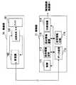
本発明の実施の形態は、有用道路の料金所等、料金課金対象エリアに通ずる道路に沿って、それぞれが基地局をなす少なくとも第一、第二の路側無線機(図1の1、2)を設け、第一、第二の路側無線機の第一、第二の無線通信領域(図1の3、4)は互いに重ならず、料金課金対象エリア(図1の5)に進入する車両(図1の17)に搭載された車載器(移動局)は、車両進行方向前方に位置する第一の無線通信領域(図1の3)に進入し、第一の路側無線機(図1の1)と無線通信し、第一の路側無線機(図1の1)は、車載器より無線送信された車載器固有情報を取得する。
【0028】
第一の路側無線機(1)は、車両進行方向後方に位置する第二の路側無線機(図1の2)に車載器固有情報を送信し、つづいて第一の路側無線機において前記車載器固有情報を破棄(削除)する。
【0029】
第二の路側無線機(2)は、第一の路側無線機(1)から送信された前記車載器固有情報を記憶手段に蓄積し、車両(17)が進行して第二の無線通信領域(4)に進入した際に、第二の路側無線機(2)は、車載器より送信された車載器固有情報を取得し、前記記憶手段に蓄積されている車載器固有情報を検索して、取得した車載器固有情報と一致するものが存在するか比較照合し、前記取得した車載器固有情報と一致する車載器固有情報が前記記憶手段に蓄積されている場合、車両(17)は料金課金対象エリア(5)に進入するものと判断して、第二の路側無線機(2)は、前記車載器に対して料金課金処理を実行し、第二の路側無線機(2)において、前記車載器に対して料金課金処理実行後、前記記憶手段に蓄積されている前記車載器の車載器固有情報を削除する。
【0030】
一方、料金課金対象エリア(5)から退出する方向に進む車両の車載器は、車両の進行方向前方に位置する第二の無線通信領域(4)に進入し、第二の路側無線機(2)と無線通信し、第二の路側無線機(2)が車載器より送信された車載器固有情報を取得する。第二の路側無線機(2)は前記車両の進行方向後方に位置する第一の路側無線機(1)に前記車載器固有情報を送信し、記憶手段に蓄積されている車載器固有情報と照合し、前記取得した車載器固有情報と一致する車載器固有情報が蓄積されていない場合、車載器にに対して料金課金処理を実行しない制御を行う。
【0031】
第一の路側無線機(1)は、第二の路側無線機(2)から送信された前記車載器固有情報を記憶手段に蓄積し、前記車両が進行して第一の無線通信領域(3)に進入した際に、第一の路側無線機(1)は、前記車載器より送信された車載器固有情報を取得し、前記蓄積されている車載器固有情報を検索し一致するものが存在するか比較照合し、前記取得した車載器固有情報と一致する車載器固有情報が前記記憶手段に存在する場合、前記車両は前記料金課金対象エリアからの退出方向に進行するものと判断して、前記車載器にに対して料金課金処理は行わない。第一の路側無線機(1)において、取得した車載器固有情報、及び蓄積されている前記取得した車載器固有情報と同一の車載器固有情報を破棄する。
【0032】
【実施例】
本発明の実施の形態についてさらに詳細に説明すべく、本発明の実施例について図面を参照して以下に説明する。図1は、本発明の一実施例を説明するための図である。均一料金入口課金方式の場合、料金課金対象の車両17は、進行方向前方の第一の路側無線機1、進行方向後方の第二の路側無線機2の順番で、路車間無線通信を行う。図1において、5は、料金課金対象エリア(例えば有料道路)であり、6は、料金課金対象エリア5への入口料金所道路であり、3、4は、路側無線機1と路側無線機2のそれぞれの無線通信領域である。路側無線機1と路側無線機2がそれぞれ有する狭域な無線通信領域3、4は互いに重なることはなく、道路に沿って縦列に配置される。なお、料金課金対象エリア5は、入口で課金されるものであれば、有料道路に限定されるものではなく、有料駐車場、催し物会場等、任意とされる。また路側無線機1、2の無線通信領域3、4は、車両一台分の長さに対応する領域として示されているが、数台、あるいはそれ以上を収容する範囲の領域としてもよい。
【0033】
図2は、本発明の一実施例の路側無線機1の構成の一例を示す図である。図2を参照すると、路側無線機1は、無線部10と、無線部10と接続される制御部11とを備えている。無線部10は、例えば図1の路側無線機1上部に架設され、アンテナ101と、送信回路と受信回路と信号分離部(切換部)よりなる送受共用部102と、変復調部103とを備えている。制御部11は、制御部11全体の動作を制御する制御回路111と、固有情報保持部112と、固有情報蓄積部113と、外部接続部114と、データ処理部(信号処理部)115と、固有情報比較部116とを備えている。データ処理部115は、無線部10の変復調部103から出力される復調データから、車載器の固有情報を抽出し、車載器の固有情報は、固有情報保持部112に保持される。固有情報比較部116は、固有情報保持部112の固有情報が、固有情報蓄積部113に蓄積されている固有情報と一致するか比較照合する処理を行う。外部接続部114は、制御回路111の制御のもと、取得した固有情報(固有情報保持部112の固有情報)を、隣接する路側無線機に通知する。アンテナ101は、例えばマイクロストリップアンテナ素子、あるいは、複数のアンテナ素子を有するアレーアンテナ等で構成され、路側無線機のビームは、所望の形状に形成され、指向性を高めた送受信ビームとなるようにしている。路側無線機の送信電力は、無線通信領域の大きさ、周囲環境等に応じて、適宜、設定される。
【0034】
図3は、本発明の一実施例の車載器の一例を示す図である。図3を参照すると、車載器は、アンテナ201と、送受信部(不図示)と、変復調部202と、データ処理部(信号処理部)203と、全体の制御を行う制御部(CPU)204と、固有情報蓄積部205とを備えている。制御部204は、例えばエンジン始動時等に、乱数を生成し、4オクテット(実際は28ビット)の2進データよりなるリンクアドレスLID(Link ID)を生成して、車載器の固有情報(識別データ)として固有情報蓄積部205に蓄積する。車載器の固有情報としては、製造番号(マニュファクチャー番号+シリアル番号)があるが、プライバシー保護等の点から、通常、リンクアドレスLIDが車載器の固有情報として用いられている。車載器は、制御部204に接続されるICカード接続部(不図示)を有し、ICカードに対して、制御部204により情報の読み書きが行われる。なお、この実施例において、車載器としては、市販のETC車載器をそのまま用いることもできる。
【0035】
本実施例の動作の一例について、図1、及び図5を参照して説明する。
【0036】
車両17が無線通信領域3に進入すると、従来の技術で説明したように、搭載された車載器(不図示)が、第一の路側無線機1からのフレームコントロールメッセージスロット(FCMS)の制御情報10(n)(図5参照)を受信し、路車間無線通信を開始する。車載器(不図示)は、その応答として、アクチベーションスロット(ACTS)に、通信要求信号を送信する。
【0037】
図1に示す場合では、第一、第二の路側無線機1、2が縦列設置されており、第一の路側無線機1は、課金対象車両の進入方向前方側として、第二の路側無線機2は、後方側として配置されている。
【0038】
路車間無線通信が開始されると、第一の路側無線機1は、車載器からアクチベーションチャネルACTC15(n)(図5参照)を受信する。アクチベーションチャネルACTC15(n)のデータ内には、車載器の固有情報(L1)(LID)が付加されており、正常に無線通信が完了した場合、第一の路側無線機1は、車載器の固有情報(L1)を、第二の路側無線機2に対して通知するとともに、自無線機では、車載器の固有情報(L1)を破棄する。第一の路側無線機1から第二の路側無線機2への車載器の固有情報(L1)の伝送方式は有線伝送あるいは無線伝送のいずれであってもよい。
【0039】
一方、第二の路側無線機2は、第一の路側無線機1より通知された車載器の固有情報(L1情報)を、蓄積する。
【0040】
続いて、車両が前進し、無線通信領域4に進入すると、第二の路側無線機2は、車載器からのACTC15(n)のデータより、車載器固有情報(L2)を取得する。
【0041】
第二の路側無線機2において、蓄積している車載器固有情報(L1)と、取得した車載器固有情報(L2)は、同じ車載器の固有情報であるため、同一となる。
【0042】
すなわち、第二の路側無線機2では、車載器から取得した車載器固有情報(L2)と一致する固有情報が、第一の路側無線機1から通知されて第二の路側無線機2の固有情報蓄積部113(図2参照)に蓄積されている車載器固有情報中に、存在するか否かを検索し、検索の結果、同じ固有情報が存在する場合には、第二の路側無線機2は、無線通信を継続して、車載器に対する料金課金処理を実行する。そして、第二の路側無線機2は、車載器に対する課金処理が正常に行われた後、第二の路側無線機2内に蓄積される車載器固有情報(L1、L2)を破棄する。すなわち、第二の路側無線機2の固有情報蓄積部113、固有情報保持部112(図2参照)の車載器固有情報(L1、L2)を削除する。
【0043】
これに対して、料金課金対象エリア5から退出する車両については、進入方向の車線の対向車線を進行し、最初に第二の無線通信領域4に進入することとなる。路車間無線通信が開始され、車両進行方向前方の第二の路側無線機2は、車載器からのACTC15(n)のデータより、車載器固有情報(L2)を取得し、第一の路側無線機1に対して通知するとともに、第二の路側無線機2は、車載器固有情報(L2)を破棄する。
【0044】
このとき、第二の路側無線機2は、蓄積している複数の車載器固有情報に車載器固有情報(L2)が存在するか否かの検索を行う。この場合、車両は、まだ無線通信領域3に進入していず、第一の路側無線機1から車載器固有情報が通知されていないため、第二の路側無線機2の固有情報蓄積部113(図2参照)には、車載器固有情報(L2)と同一の固有情報は存在しない。このため、第二の路側無線機2は、車載器に対する料金課金処理は実行しない。
【0045】
さらに、車両が前進して、無線通信領域3に進入すると、第一の路側無線機1は、車載器から無線送信されたACTC15(n)のデータより固有情報(L1)を取得する。
【0046】
第一の路側無線機1は、第一の路側無線機1の固有情報蓄積部113(図2参照)に蓄積されている車載器固有情報の中に、固有情報(L1)と同じ固有情報が存在するか否かを検索し、同じ固有情報が存在した場合には、L1及びL2を破棄する。そして、同一の固有情報が存在する場合、第一の路側無線機1は、車両が退出方向に進行していると判断し、車載器に対する料金課金処理を実行することはない。
【0047】
本実施例においては、上記した動作により、料金課金対象エリア5へ進入する車両に対してのみの、料金課金が可能となる。
【0048】
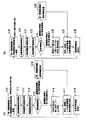
図4(a)、図4(b)は、上記した第一の路側無線機1、第二の路側無線機2の処理手順をそれぞれ流れ図で表したものである。図1乃至図4を参照して、第一の路側無線機1と第二の路側無線機2の処理手順について以下に説明する。
【0049】
はじめに図4(a)を参照すると、第一の路側無線機1は、第二の路側無線機2より車載器固有情報を受信した場合、車載器固有情報を固有情報蓄積部113(図2参照)に蓄積する(ステップS10)。なお、第一の路側無線機1において、この処理ステップは、車両が料金課金対象エリア5から退出方向に進行時に実行される。
【0050】
第一の路側無線機1は、無線通信領域3に進入した車両17の車載器と路車間無線通信を開始し、車載器固有情報を取得し、取得した車載器固有情報を、固有情報保持部112(図2参照)に保持する(ステップS11〜S13)。
【0051】
つづいて、第一の路側無線機1は、固有情報蓄積部113に蓄積されている車載器固有情報を検索し、取得した車載器固有情報と同一の固有情報が蓄積されているか照合判定し(ステップS14)、同じ固有情報が無い場合には(進入方向と判断する)、外部接続部114より、第二の路側無線機2に対して、取得した車載器固有情報を送信し(ステップS15)、さらに、保持していた車載器固有情報を廃棄し(ステップS17)、路車間無線通信待ちとなる(ステップS18)。
【0052】
第一の路側無線機1において、ステップS14の照合の結果、固有情報蓄積部113に同じ固有情報が存在する場合、車両が退出方向に進行しているものと判断し(ステップS16)、固有情報保持部112に保持している車載器固有情報と、固有情報蓄積部113に蓄積していた車載器固有情報(固有情報保持部112に保持している車載器固有情報と同一の固有情報)を廃棄し(ステップS17)、路車間無線通信待ちとなる(ステップS18)。ステップS18の待ち状態において、無線通信領域3に進入した車両17の車載器と通信する場合、ステップS11からの処理が開始され、第二の路側無線機2より車載器固有情報を受信した場合には、ステップS10からの処理が開始される。
【0053】
次に図4(b)を参照すると、第二の路側無線機2は第一の路側無線機1より車載器固有情報を受信した場合、車載器固有情報を固有情報蓄積部113(図2参照)に蓄積する(ステップS20)。なお、第二の路側無線機2において、この処理ステップは、車両が料金課金対象エリア5への入場方向に進行時に実行される。
【0054】
第二の路側無線機2は、無線通信領域4に進入した車両17の車載器と路車間無線通信を開始し、車載器固有情報を取得し、取得した車載器固有情報を、固有情報保持部112(図2参照)に保持する(ステップS21〜S23)。
【0055】
つづいて、第二の路側無線機2は、固有情報蓄積部113(図2参照)に蓄積されている車載器固有情報を検索し、取得した車載器固有情報と同一の固有情報と同じものがあるか照合判定し(ステップS24)、同じ固有情報が無い場合には(退出方向と判断する)、外部接続部114より、第一の路側無線機1に対して、取得した車載器固有情報を送信し(ステップS25)、保持していた車載器固有情報を廃棄し(ステップS27)、路車間無線通信待ちとなる(ステップS28)。
【0056】
第二の路側無線機2において、ステップS24の照合の結果、固有情報蓄積部113に同じ固有情報が存在する場合、車両が入場方向に進行しているものと判断し(ステップS26)、固有情報保持部112に保持している車載器固有情報と、固有情報蓄積部113に蓄積していた車載器固有情報(固有情報保持部112に保持している車載器固有情報と同一の固有情報)を廃棄し(ステップS27)、路車間無線通信待ちとなる(ステップS28)。ステップS28の待ち状態において、無線通信領域4に進入した車両17の車載器と通信する場合、ステップS21からの処理が開始され、第一の路側無線機1より車載器固有情報を受信した場合には、ステップS20からの処理が開始される。
【0057】
上記実施例では、第一、第二の路側無線機1、2の2台の構成により、料金課金処理を実現しているが、料金課金処理に関わる送受信詳細データ量が大きく路車間無線通信に通信時間を要する場合には、さらに複数の路側無線機を設置して実施することも可能である。
【0058】
また、上記実施例において、第一、第二の路側無線機1、2の無線通信領域3、4は、複数台の車両を収容可能なサイズとしてもよい。この場合、複数台の車両の車載器は、路側無線機(基地局)に対して、車載器に許可されているタイムスロットでデータを送信する。
【0059】
本発明によれば、有料道路の料金所等、限定された設置環境に制限されることなく、一般の道路においても、車載器に対して、ノンストップで料金課金することが可能となる。
【0060】
本発明が適用されるシステムは、料金一定の有料道路入口料金所の自動料金収受システム(ETC)に限定されるものではなく、例えば料金一定の有料道路出口料金所の自動料金収受システム(ETC)にも適用できる。この場合、有料道路へ入る車(車載器)には課金せず、有料道路から出てくる車(車載器)に課金する。さらに、本発明は、例えば外部より首都圏内に流入する車に対して課金するロードプライシング(Road Pricing)システムにおいて、高速道路又は主用国道等の所定の関門において、路側無線機を少なくとも2式設け、首都圏内に進入する車両について課金する構成としてもよい。
【0061】
さらに、本発明は、有料駐車場におけるノンストップ課金システムにもそのまま適用できる。例えば遊園地やテーマパーク等の駐車場への入場をスムーズなものとし、駐車場入口での渋滞を回避することができる。さらに、本発明は、ガソリンスタンド、コンビニ、ドライブスルー店舗等における、ノンストップ課金システムにも、そのまま適用できる。この場合、店舗等において商品の精算において、現金等による支払いは不要とされており、例えば商品の発注場所から出口までの間の区間において、本発明のシステムの路側無線機から車載器のICカードに対して課金処理が行われる。この場合、出口方向から進入した車両に対しては、第一、第二の基地局(路側無線機)より、反対方向と判断されるため、課金が行われることはない。
【0062】
さらにまた、本発明は、駅構内、ホーム等における盲人等の方向案内システムにも適用可能である。盲人等の保持する無線端末(移動局)と、一の方向に沿って配設された、複数の基地局との間の通信により、移動局の固有情報を基地局が取得して、移動局の進行方向を判別し、例えば、順方向への進行の場合、そのまま進行してよいことを案内し、禁止場所への進入あるいは目的の場所への進行とは逆の方向へ進行することを検出した場合、アラームを発して警告する等の処理を行うというものである。
【0063】
なお、第1、第2の基地局の双方に接続される制御局あるいは管理センターを備えた構成とし、第1の基地局が移動局から固有情報を受け取った場合、制御局あるいは管理センターに固有情報を送信し、つづいて、第1の基地局に対して移動局の進行方向後方に位置する第2の基地局が、前記移動局から固有情報を受け取った場合、基地局よりも上位の前記制御局あるいはセンターに固有情報を送信し、制御局あるいは管理センターにおいて、第2の基地局から受け取った固有情報が、第1の基地局から先に送信され蓄積保持している固有情報と一致するか、比較照合することで、移動局の進行方向を判定し、判定結果に応じて、第2の基地局を介して、移動局に対する処理の実行の有無の指示を行うようにしてもよい。
【0064】
【発明の効果】
以上説明したように、本発明によれば、料金課金を要する方向に進行する車両に対してのみ路車間無線通信により、ノンストップで正確な料金課金を行うことができる、という効果を奏する。また本発明によれば、移動局の進行方向に応じた処理を適切に行うことができる、という効果を奏する。
【図面の簡単な説明】
【図1】本発明の一実施例のシステム構成を示す図である。
【図2】本発明の一実施例の路側無線機の構成を示す図である。
【図3】本発明の一実施例の車載器の構成を示す図である。
【図4】本発明の一実施例における第一、第二の路側無線機の処理手順を示す流れ図である。
【図5】路側無線機及び車載器送信データフォーマットを示す図である。
【符号の説明】
1 第一の路側無線機
2 第二の路側無線機
3 第一の無線通信領域
4 第二の無線通信領域
5 料金課金対象エリア
6 道路
7 ガードタイム
8 プリアンブル
9 ユニークワード1
10 制御情報
11 CRC(誤り検査情報)
12 ガードタイム
13 ユニークワード2
14 データ
15 アクチベーションチャネル(ACTC)
16 ガードタイム
17 車両[0001]
BACKGROUND OF THE INVENTION
The present invention relates to a non-stop automatic toll collection system, which is a field of intelligent transport systems (ITS), and more particularly to a system and method suitable for application to toll charges for on-vehicle equipment.
[0002]
[Prior art]
Recently, roadside unit antennas (base station antennas) installed on toll gates on toll roads such as expressways and on-vehicle equipment (mobile stations) mounted on vehicles communicate wirelessly, and enter or exit In the in-vehicle device that transmits the fee billing information wirelessly to the in-vehicle device and receives the fee information, for example, an accounting process such as deducting the corresponding fee by an electronic payment method using an IC card or the like connected to the on-vehicle device is executed. In addition, a non-stop automatic toll collection system that allows electronic payment of tolls without stopping at the toll booth is used. An in-vehicle device of an automatic toll collection system (Electrical Toll Collection: “ETC”) is commercially available, and is attached to a dashboard of a vehicle, for example.
[0003]
The fee charging method for the vehicle-mounted device in the non-stop automatic toll collection system will be described by taking a conventional flat fee entrance charging method (charging the vehicle-mounted device at the entrance toll gate on the toll road as a flat fee) as an example.
[0004]
Road-to-vehicle wireless communication between the roadside wireless device (base station) and the vehicle-mounted device constituting the mobile station is performed by a control signal transmitted by the roadside wireless device.
[0005]
When the vehicle-mounted device approaches the entrance toll gate of the toll road and enters the narrow wireless communication area of the roadside wireless device, the vehicle-mounted device receives the control signal transmitted by the roadside wireless device.
[0006]
An example of the format of the data continuously transmitted by the roadside wireless device and the data transmitted by the vehicle-mounted device is shown in FIG. In addition, FIG. 5 is the 41st document (published by the Japan Radio Industry Association, “(Draft) Automatic Toll Collection System”, December 1999, Revised 1.2, ARIB STD-T55). It was created anew based on the contents of the page. FIG. 5 shows an example of the formats of the downlink (transmission data from the base station (roadside radio)) and the uplink (transmission data from the mobile station (vehicle equipment)). Referring to FIG. 5, the data has a frame structure, and one frame is composed of a plurality of slots. The first control signal in the frame (referred to as “Na slot”) controls the mobile station (vehicle equipment).
[0007]
The Na slot is called a frame control message slot (FCMS), and is a frame multiplexing slot. One slot is arranged at the head of the frame, dedicated to the downlink, and includes frame control information and TDMA slot allocation information. This is a communication control slot for transmitting a frame control message channel (FCMC) consisting of An outline of the control information will be described below. None of them is shown in the figure. Transmission channel control field SIG (Signaling) such as 2-
[0008]
When road-to-vehicle wireless communication is not performed, the roadside wireless device forming the base station transmits only the Na slot, and Nb and Nc become empty slots.
[0009]
When the vehicle-mounted device forming the mobile station enters the wireless communication area, the vehicle-mounted device first detects the unique word (UW1) 9 (n) in the Na slot of the signal transmitted from the roadside wireless device. Synchronizes its own time slot with the roadside radio.
[0010]
Subsequently, the vehicle-mounted device receives the subsequent control information 10 (n) in the unique word (UW1) 9 (n) and performs a data error check using the error check code (CRC) 11 (n). If no error occurs as a result of the error check, the contents of the control information 10 (n) are analyzed, and the activation channel (radio link connection request signal) ACTC ( Activation Channel) 15 (n) is transmitted to the roadside radio. The activation slot (ACTS) is dedicated to the uplink, and six channels for activation channels (Activation Channels) for the mobile station to register to the communication link of the base station are arranged. During the link establishment phase, the mobile station A certain vehicle-mounted device selects one of these windows and transmits an ACTC to the base station.
[0011]
The roadside wireless device that has received ACTC15 (n) from the on-vehicle device notifies the reception time slot of the on-vehicle device by the control information 10 (n + 1) (not shown) in the (N + 1) a slot, and (N + 1) Data is transmitted to the vehicle-mounted device in the b slot or the (N + 1) c slot.
[0012]
Control information 10 (n + 1) includes
・ Roadside radio type,
-Link address field LID (Link ID) information etc. for the vehicle-mounted device is included.
[0013]
Further, when the vehicle-mounted device successfully receives the data in the (N + 1) b slot or (N + 1) c slot, the contents of the data are analyzed, and the transmission time indicated by the roadside radio device in the frame control message slot (FCMS) Response data is returned in the slot.
[0014]
The data 14 (n) in the Nb slot or the Nc slot includes detailed information related to the charge billing transmitted / received between the roadside wireless device and the vehicle-mounted device, and normal billing processing is executed by exchanging these data. Is done.
[0015]
The above-described conventional fee billing processing system can operate normally when the roadside wireless device is installed in a limited place such as an entrance toll gate such as a toll road.
[0016]
However, when this system is applied to a general road and applied to a system that charges a vehicle that enters into an area that needs to be charged, there is a problem that erroneous charging occurs for the vehicle. Have.
[0017]
In other words, on ordinary roads with two-way traffic, especially on narrow lanes with opposite traffic, unlike cars that enter the toll gate of toll roads that are one-way, vehicles leaving the chargeable area are It must pass through the wireless communication area of the radio.
[0018]
For this reason, the vehicle-mounted device performs road-to-vehicle wireless communication with the roadside wireless device even when leaving the vehicle, and in this state, the vehicle is charged, and erroneous charging occurs unless some charging protection is applied.
[0019]
In addition, as a technique for performing charging suppression control according to the traveling direction of the vehicle, for example, in Japanese Patent Laid-Open No. 8-69598, a normal traveling can be charged for a vehicle traveling in the forward direction, and the vehicle travels in the opposite lane. As a toll collection system that reliably prohibits charging for vehicles, the first and second antennas are installed in the vicinity of the toll booth in the direction of travel of the vehicle, and between the in-vehicle device mounted on the vehicle Wireless communication is performed in a contactless manner, charges are received from the first antenna and the second antenna, and information including different antenna numbers is transmitted from the first antenna and the second antenna. When the vehicle is traveling in the opposite lane, a reverse flag is set and charging is prohibited, and the reverse flag is set on the in-vehicle device. Have A toll collection system has been proposed in which the time is measured with a timer and a fixed time elapses or when entering the communication area of a toll booth antenna with different location information, the reverse running flag is cleared and communication is enabled. . In this toll collection system, control is performed in which the in-vehicle device side determines the traveling direction based on information transmitted from the antenna and prohibits charging when the reverse-travel flag on the in-vehicle device is on. In the case of such a configuration, for example, by setting the reverse running flag to ON by tampering or the like on the vehicle-mounted device side, an opportunity to bypass the charge bill is given.
[0020]
[Problems to be solved by the invention]
Therefore, the problem to be solved by the present invention is that, in a toll billing system that charges a uniform fee at a toll gate on a toll road, only for vehicles traveling in a direction requiring toll billing, non-stop by road-to-vehicle wireless communication. It is an object to provide a method and a system capable of accurately charging a fee.
[0021]
As will be apparent from the following description, the present invention can be applied to various systems in which the mobile station is managed on the base station side in addition to the fee billing system.
[0022]
[Means for Solving the Problems]
The present invention for providing means for solving the above-mentioned problems is that the base station among a plurality of base stations connected to communicate with each other is wirelessly communicated with a mobile station that has entered a wireless communication range of the one base station. The unique information related to the mobile station is acquired, and the specific information related to the mobile station acquired in the one base station is located behind the base station in the traveling direction of the mobile station. And the other base station acquires specific information related to the mobile station by wireless communication with the mobile station that has entered the wireless communication range of the other base station, and the other base station Whether the traveling direction of the mobile station is a predetermined forward direction by comparing whether the unique information related to the mobile station acquired in
[0023]
The present invention includes a plurality of roadside wireless devices, and one roadside wireless device that wirelessly communicates with the vehicle-mounted device is positioned behind the roadside wireless device with unique information acquired from the vehicle-mounted device by road-to-vehicle wireless communication. To determine whether the unique information acquired from the vehicle-mounted device by road-to-vehicle wireless communication matches the unique information notified from the one roadside wireless device. Thus, it is determined whether the traveling direction is entering or leaving the fee-charging area, and based on the determination result, charging is controlled. As will be apparent from the following description, each of the inventions in the claims of the present application provides means for solving the above-mentioned problems.
[0024]
DETAILED DESCRIPTION OF THE INVENTION
Embodiments of the present invention will be described. The present invention uses at least two types of roadside radios that have conventionally been used only for one set, and based on the unique information of the onboard equipment, which onboard equipment and road-to-vehicle wireless communication were performed. A function for accumulating such history information is added, and this history information is shared between the above two types of roadside wireless devices.
[0025]
The first roadside radio installed on the front side as viewed from the vehicle that is about to enter the chargeable area is the second roadside installed on the rear side of the unique information acquired from the vehicle-mounted device. Notify the radio.
[0026]
In addition, the second roadside wireless device determines the traveling direction of the vehicle from the notified in-vehicle device specific information, and performs billing only when necessary.
[0027]
In the embodiment of the present invention, at least first and second roadside radio devices (1 and 2 in FIG. 1) each forming a base station along a road that leads to a toll-chargeable area such as a toll booth on a useful road The first and second wireless communication areas (3 and 4 in FIG. 1) of the first and second roadside wireless devices do not overlap each other and enter the toll chargeable area (5 in FIG. 1). The in-vehicle device (mobile station) mounted on (17 in FIG. 1) enters the first wireless communication area (3 in FIG. 1) located in front of the vehicle traveling direction, and the first roadside wireless device (FIG. 1). 1) and the first roadside wireless device (1 in FIG. 1) acquires the vehicle-mounted device specific information wirelessly transmitted from the vehicle-mounted device.
[0028]
The first roadside wireless device (1) transmits the vehicle-mounted device specific information to the second roadside wireless device (2 in FIG. 1) located rearward in the vehicle traveling direction, and then the vehicle is mounted on the vehicle by the first roadside wireless device. Discard device specific information.
[0029]
The second roadside radio (2) accumulates the in-vehicle device specific information transmitted from the first roadside radio (1) in the storage means, and the vehicle (17) advances to the second radio communication area. When entering (4), the second roadside radio (2) acquires the on-vehicle device specific information transmitted from the on-vehicle device, and searches the on-vehicle device specific information stored in the storage means. If the on-vehicle device specific information that matches the acquired on-vehicle device unique information is stored in the storage means, the vehicle (17) is charged. The second roadside wireless device (2) determines to enter the chargeable area (5), and executes the fee charging process for the on-vehicle device. In the second roadside wireless device (2), The vehicle stored in the storage means after executing the charge billing process for the on-vehicle device To delete a vehicle-mounted device-specific information of the vessel.
[0030]
On the other hand, the vehicle-mounted device of the vehicle traveling in the direction of leaving the chargeable area (5) enters the second wireless communication area (4) located in front of the traveling direction of the vehicle, and the second roadside wireless device (2 ) And the second roadside wireless device (2) acquires the vehicle-mounted device specific information transmitted from the vehicle-mounted device. The second roadside radio (2) transmits the onboard equipment specific information to the first roadside radio (1) located behind the vehicle in the traveling direction, and the onboard equipment specific information stored in the storage means If the vehicle-mounted device specific information that matches the acquired vehicle-mounted device specific information is not accumulated, the vehicle-mounted device is controlled so as not to execute the fee billing process.
[0031]
The first roadside wireless device (1) accumulates the vehicle-mounted device specific information transmitted from the second roadside wireless device (2) in the storage means, and the vehicle travels to the first wireless communication area (3 ), The first roadside wireless device (1) acquires the vehicle-mounted device specific information transmitted from the vehicle-mounted device, and searches the stored vehicle-mounted device specific information to find a match. If the vehicle-mounted device specific information that matches the acquired vehicle-mounted device specific information is present in the storage means, the vehicle is determined to proceed in the direction of exit from the chargeable area, No fee billing process is performed on the in-vehicle device. In the first roadside wireless device (1), the acquired OBE specific information and the OBE specific information that is the same as the acquired OBE specific information stored are discarded.
[0032]
【Example】
In order to describe the embodiment of the present invention in more detail, examples of the present invention will be described below with reference to the drawings. FIG. 1 is a diagram for explaining an embodiment of the present invention. In the case of the uniform fee entrance charging method, the
[0033]
FIG. 2 is a diagram illustrating an example of the configuration of the
[0034]
FIG. 3 is a diagram illustrating an example of the vehicle-mounted device according to the embodiment of the present invention. Referring to FIG. 3, the vehicle-mounted device includes an
[0035]
An example of the operation of this embodiment will be described with reference to FIG. 1 and FIG.
[0036]
When the
[0037]
In the case shown in FIG. 1, the first and second
[0038]
When road-to-vehicle wireless communication is started, the
[0039]
On the other hand, the
[0040]
Subsequently, when the vehicle moves forward and enters the wireless communication area 4, the second
[0041]
In the second
[0042]
That is, in the second
[0043]
On the other hand, a vehicle leaving the toll
[0044]
At this time, the
[0045]
Further, when the vehicle moves forward and enters the wireless communication area 3, the first
[0046]
The first
[0047]
In the present embodiment, it is possible to charge a fee only for a vehicle entering the fee charging
[0048]
FIGS. 4A and 4B are flowcharts showing the processing procedures of the first
[0049]
First, referring to FIG. 4A, when the
[0050]
The first
[0051]
Subsequently, the first
[0052]
In the first
[0053]
Next, referring to FIG. 4 (b), when the
[0054]
The second
[0055]
Subsequently, the
[0056]
In the second
[0057]
In the above embodiment, the fee billing process is realized by the configuration of the first and second
[0058]
Moreover, in the said Example, the radio | wireless communication area | regions 3 and 4 of the 1st, 2nd roadside radio |
[0059]
According to the present invention, it is possible to charge the vehicle-mounted device in a non-stop manner on a general road without being limited to a limited installation environment such as a toll gate on a toll road.
[0060]
The system to which the present invention is applied is not limited to an automatic toll collection system (ETC) for a toll road entrance toll gate with a fixed fee. For example, an automatic toll collection system (ETC) for a toll road exit toll gate with a fixed fee. It can also be applied to. In this case, the vehicle (onboard device) entering the toll road is not charged, but the vehicle (onboard device) coming out of the toll road is charged. Furthermore, the present invention provides, for example, a road pricing system that charges a vehicle flowing into the metropolitan area from the outside, for example, at least two sets of roadside radios at a predetermined barrier such as an expressway or a main national road. The vehicle may be charged for vehicles entering the metropolitan area.
[0061]
Furthermore, the present invention can be directly applied to a non-stop billing system in a pay parking lot. For example, entrance to a parking lot such as an amusement park or a theme park can be made smooth, and traffic jams at the entrance of the parking lot can be avoided. Furthermore, the present invention can be directly applied to a non-stop billing system in a gas station, a convenience store, a drive-through store, or the like. In this case, payment by cash or the like is not required in the checkout of the product at the store or the like. For example, in the section from the place where the product is ordered to the exit, the IC card of the vehicle-mounted device from the roadside radio of the system of the present invention Is charged. In this case, the vehicle entering from the exit direction is determined to be in the opposite direction by the first and second base stations (roadside radios), so that no charge is made.
[0062]
Furthermore, the present invention can also be applied to a direction guidance system for blind persons in stations, platforms, and the like. By communicating between a wireless terminal (mobile station) held by a blind person or the like and a plurality of base stations arranged along one direction, the base station acquires specific information of the mobile station, and the mobile station For example, if you are traveling in the forward direction, you can proceed as it is.No When it is detected that the vehicle is traveling in the direction opposite to the entry to the prohibited place or the destination place, an alarm is issued and a warning is performed.
[0063]
When the first base station receives specific information from the mobile station, the control station or management center is connected to both the first and second base stations. Information is transmitted, and then, when the second base station located behind the moving direction of the mobile station with respect to the first base station receives specific information from the mobile station, the higher-order base station The unique information is transmitted to the control station or the center, and the unique information received from the second base station in the control station or the management center matches the unique information that is transmitted from the first base station first and stored and held. Alternatively, the traveling direction of the mobile station may be determined by comparison and collation, and instructing whether or not to execute the process to the mobile station may be performed via the second base station according to the determination result.
[0064]
【The invention's effect】
As described above, according to the present invention, there is an effect that non-stop and accurate fee charging can be performed by road-to-vehicle wireless communication only for vehicles traveling in a direction that requires fee charging. Moreover, according to the present invention, there is an effect that processing according to the traveling direction of the mobile station can be appropriately performed.
[Brief description of the drawings]
FIG. 1 is a diagram showing a system configuration of an embodiment of the present invention.
FIG. 2 is a diagram illustrating a configuration of a roadside wireless device according to an embodiment of the present invention.
FIG. 3 is a diagram showing a configuration of an in-vehicle device according to an embodiment of the present invention.
FIG. 4 is a flowchart showing a processing procedure of the first and second roadside wireless devices in one embodiment of the present invention.
FIG. 5 is a diagram showing a roadside radio device and on-vehicle device transmission data format.
[Explanation of symbols]
1 First roadside radio
2 Second roadside radio
3 First wireless communication area
4 Second wireless communication area
5 Chargeable area
6 road
7 Guard time
8 Preamble
9
10 Control information
11 CRC (Error check information)
12 Guard time
13
14 data
15 Activation Channel (ACTC)
16 Guard time
17 Vehicle
Claims (17)
Translated fromJapanese前記一の基地局で取得した前記移動局に関連する固有情報を、前記一の基地局に対して前記移動局の進行方向の後方に位置する他の基地局に通知する手段と、
を備え、
前記他の基地局が、前記他の基地局の無線通信範囲に入った前記移動局との無線通信により、前記移動局から、前記移動局に関連する固有情報を取得する手段と、
前記他の基地局で取得した前記移動局に関連する固有情報が、前記一の基地局から通知された前記固有情報と一致するか比較することで、前記移動局の進行方向があらかじめ定められた順方向であるか、逆方向であるかを判別する手段と、
前記移動局の進行方向の判別結果に基づき、前記移動局に対して、あらかじめ定められた処理の実行の有無を制御する手段と、
を備えている、ことを特徴とする移動局管理システム。Among the plurality of basestations are disposed separated from each other in one direction along the moving direction of the mobile station is communicatively connected to each other, one base station enters the radio communication area of said one base stationthe mobile Means for acquiring specific information related to themobile station from the mobile station by wireless communication with thestation ;
Means for notifying the one base station of other information related to the mobile station acquired by the one base station to another base station located behind the traveling direction of the mobile station;
With
Means for acquiring unique information related to themobile station from the mobile station by wireless communication with the mobile station that has entered the wireless communication range of the other base station;
The traveling direction of the mobile station is determined in advance by comparing whether the unique information related to the mobile station acquired by the other base station matches the unique information notified from the one base station. Means for determining whether the direction is forward or reverse;
Based on the determination result of the traveling direction of the mobile station, the means for controlling the presence or absence of execution of a predetermined process for the mobile station;
A mobile station management system comprising:
車両に搭載される車載器と無線通信する一の路側無線機が、路車間無線通信により前記車載器より取得した固有情報を、前記一の路側無線機に対して車両進行方向後方に位置する他の路側無線機に通知する手段を備え、
前記他の路側無線機では、路車間無線通信により前記車載器より取得した固有情報が、前記一の路側無線機から通知された前記固有情報と一致するか比較判定して、前記車両の進行方向が前記料金課金対象エリアへの進入であるか退出であるか判別し、前記判別結果に基づき、料金課金処理の実行の有無を制御する手段を備えている、ことを特徴とする料金課金システム。A plurality of roadside radios are provided apart from each other along the road leading to the chargeable area,
A roadside wireless device that wirelessly communicates with an on-vehicle device mounted on a vehicle has unique information acquired from the on-vehicle device by road-to-vehicle wireless communication, and is located behind the one roadside wireless device in the vehicle traveling direction. Means to notify the roadside radio of
In the other roadside wireless device, the traveling direction of the vehicle is determined by comparing whether the unique information acquired from the vehicle-mounted device by road-to-vehicle wireless communication matches the unique information notified from the one roadside wireless device. A charge billing system comprising: a means for determining whether or not the vehicle is entering or leaving the charge billing area and controlling whether or not charge billing processing is executed based on the determination result.
前記料金課金対象エリアに進入する車両に搭載される車載器は、前記車両の進行方向前方に位置する前記第一の路側無線機と無線通信し、
前記第一の路側無線機が、前記車載器より無線送信された車載器固有情報を取得し、前記車両の進行方向後方に位置する前記第二の路側無線機に対して前記車載器固有情報を通知する手段を備え、
前記第二の路側無線機は、前記第一の路側無線機から通知された前記車載器固有情報を記憶手段に蓄積する手段と、
前記車載器より無線送信された車載器固有情報を取得し、前記記憶手段に蓄積されている車載器固有情報を検索して前記取得した車載器固有情報と一致するものが存在するか比較照合する手段と、
前記取得した車載器固有情報と一致する車載器固有情報が前記記憶手段に存在する場合、前記車両は前記料金課金対象エリアに進入するものと判断して、前記車載器に対して料金課金処理を実行する手段と、
前記車載器に対して料金課金処理を実行した後、前記記憶手段に蓄積されている前記車載器の車載器固有情報を削除する手段と、
を備えている、ことを特徴とする料金課金システム。At least first and second roadside radios are separated from each other along the road leading to the chargeable area, and the radio communication areas of the first and second roadside radios do not overlap each other,
The vehicle-mounted device mounted on the vehicle entering the chargeable area is wirelessly communicated with the first roadside wireless device located forward in the traveling direction of the vehicle,
The first roadside wireless device acquires the vehicle-mounted device specific information wirelessly transmitted from the vehicle-mounted device, and the vehicle-mounted device specific information is obtained with respect to the second roadside wireless device located behind the vehicle in the traveling direction. With a means of notification,
The second roadside radio is a means for storing the in-vehicle device specific information notified from the first roadside radio in a storage means;
The OBE specific information wirelessly transmitted from the OBE is acquired, the OBE specific information stored in the storage unit is searched, and it is compared and checked whether there is a match with the acquired OBE specific information. Means,
When the vehicle-mounted device specific information that matches the acquired vehicle-mounted device specific information is present in the storage means, the vehicle is determined to enter the chargeable area, and the fee-charging process is performed on the vehicle-mounted device. Means to perform,
Means for deleting the OBE specific information of the OBE stored in the storage means after executing the charge billing process for the OBE;
A billing system characterized by comprising:
前記第二の路側無線機が前記車載器より無線送信された車載器固有情報を取得し、前記車両の進行方向後方に位置する前記第一の路側無線機に前記車載器固有情報を通知する手段を備え、
前記第二の路側無線機は、前記車載器より無線送信された車載器固有情報を取得し、前記記憶手段に蓄積されている車載器固有情報と照合し、前記取得した車載器固有情報と一致する車載器固有情報が前記記憶手段に存在しない場合には、前記車載器に対して料金課金処理を実行せず、
前記第一の路側無線機は、前記第二の路側無線機から通知された前記車載器固有情報を記憶手段に蓄積する手段と、
前記車載器より無線送信された車載器固有情報を取得し、前記記憶手段に蓄積されている車載器固有情報を検索し、一致するものが存在するか比較照合する手段と、
前記取得した車載器固有情報と一致する車載器固有情報が前記記憶手段に存在する場合、前記車両が前記料金課金対象エリア退出方向に進行するものと判断して、前記車載器に対する料金課金処理を抑止するように制御する手段と、
を備えている、ことを特徴とする請求項7記載の料金課金システム。The vehicle-mounted device of the vehicle traveling in the direction of exiting from the chargeable area is wirelessly communicated with the second roadside wireless device located in the forward direction of the vehicle,
Means for the second roadside wireless device to acquire the vehicle-mounted device specific information wirelessly transmitted from the vehicle-mounted device and to notify the vehicle-mounted device specific information to the first roadside wireless device located behind the vehicle in the traveling direction. With
The second roadside radio acquires the OBE specific information wirelessly transmitted from the OBE, collates with the OBE specific information stored in the storage unit, and matches the acquired OBE specific information. If the in-vehicle device specific information to be present does not exist in the storage unit, the charge accounting process is not performed on the on-vehicle device,
The first roadside radio is configured to store in-vehicle device specific information notified from the second roadside radio in a storage means;
Means for acquiring OBE-specific information wirelessly transmitted from the OBE, searching the OBE-specific information stored in the storage means, and comparing and checking whether there is a match;
When the vehicle-mounted device specific information that matches the acquired vehicle-mounted device specific information exists in the storage unit, it is determined that the vehicle travels in the direction of exiting the chargeable area, and the fee charging process for the vehicle-mounted device is performed. Means to control to deter,
The charge billing system according to claim 7, further comprising:
前記一の基地局で取得した前記移動局に関連する固有情報を、前記一の基地局に対して前記移動局の進行方向の後方に位置する他の基地局に通知するステップと、
前記他の基地局が、前記他の基地局の無線通信範囲に入った前記移動局との無線通信により、前記移動局から、前記移動局に関連する固有情報を取得するステップと、
前記他の基地局で取得した前記移動局に関連する固有情報が、前記一の基地局から通知された前記固有情報と一致するか比較することで、前記移動局の進行方向があらかじめ定められた順方向であるか、逆方向であるかを判別するステップと、
前記移動局の進行方向の判別結果に基づき、前記移動局に対して、あらかじめ定められた処理の実行の有無を制御するステップと、
を含む、ことを特徴とする移動局管理方法。One base station among a plurality of base stationsthat are spaced apart from each other in one direction along the moving direction of the mobile station and connected to each other is connected to a mobile station that is in a wireless communication range of the one base station. Acquiring unique information related to themobile station from the mobile station by wireless communication of:
Notifying specific information related to the mobile station acquired by the one base station to another base station located behind the traveling direction of the mobile station to the one base station;
The other base station acquires unique information related to themobile station from the mobile station by wireless communication with the mobile station that has entered the wireless communication range of the other base station;
The traveling direction of the mobile station is determined in advance by comparing whether the unique information related to the mobile station acquired by the other base station matches the unique information notified from the one base station. Determining whether it is forward or reverse;
Based on the determination result of the traveling direction of the mobile station, controlling the presence or absence of execution of a predetermined process for the mobile station;
A mobile station management method comprising:
前記一の基地局で取得した前記移動局に関連する固有情報を、前記一の基地局に接続される制御局またはセンターに通知するステップと、
前記一の基地局に対して前記移動局の進行方向後方に位置する他の基地局が、前記他の基地局の無線通信範囲に入った前記移動局との無線通信により、前記移動局から、前記移動局に関連する固有情報を取得するステップと、
前記他の基地局で取得した前記移動局に関連する固有情報を、前記他の基地局に接続される前記制御局またはセンターに通知するステップと、
前記制御局またはセンターでは、前記他の基地局で取得した前記移動局に関連する固有情報が、前記一の基地局から先に通知された前記固有情報と一致するか比較することで、前記移動局の進行方向があらかじめ定められた順方向であるか、逆方向であるかを判別するステップと、
前記移動局の進行方向の判別結果に基づき、前記第二の基地局を介して前記移動局に対して、あらかじめ定められた処理の実行の有無を制御するステップと、
を含むことを特徴とする移動局管理方法。A base station that performs radio communication withthe mobile station, by acquiringfrom the mobile station specific information related to the mobile station by radio communication withthe mobile station ;
Notifying specific information related to the mobile station acquired by the one base station to a control station or center connected to the one base station;
Another base station located behind the one base station in the traveling direction of themobile station, from the mobile station by wireless communication with the mobile station that has entered the wireless communication range of the other base station, Obtaining unique information associated with the mobile station;
Notifying the control station or center connected to the other base station of the specific information related to the mobile station acquired by the other base station;
In the control station or the center, by comparing whether the specific information related to the mobile station acquired by the other base station matches the specific information previously notified from the one base station, the mobile station Determining whether the direction of travel of the station is a predetermined forward direction or a reverse direction;
Based on the determination result of the traveling direction of the mobile station, controlling the presence or absence of execution of a predetermined process for the mobile station via the second base station;
A mobile station management method comprising:
車両に搭載される車載器と無線通信する一の路側無線機が、路車間無線通信により前記車載器より取得した固有情報を、前記一の路側無線機に対して車両進行方向後方に位置する他の路側無線機に通知するステップと、
前記他の路側無線機では、路車間無線通信により前記車載器より取得した固有情報が、前記一の路側無線機から通知された前記固有情報と一致するか判定して、前記車両の進行方向が前記料金課金対象エリアへの進入であるか退出であるか判別し、前記判別結果に基づき、料金課金処理を行うように制御するステップと、
を含むことを特徴とする料金課金方法。Deploy roadside radios separated from each other along the road leading to the chargeable area,
A roadside wireless device that wirelessly communicates with an on-vehicle device mounted on a vehicle has unique information acquired from the on-vehicle device by road-to-vehicle wireless communication, and is located behind the one roadside wireless device in the vehicle traveling direction. Notifying the roadside radio of
In the other roadside wireless device, it is determined whether the unique information acquired from the vehicle-mounted device by road-to-vehicle wireless communication matches the unique information notified from the one roadside wireless device, and the traveling direction of the vehicle is determined. Determining whether to enter or leave the fee-charging area, and controlling to perform fee-charging processing based on the determination result;
A charge billing method characterized by including:
前記料金課金対象エリアに進入する車両の車載器は、前記車両の進行方向前方に位置する前記第一の無線通信領域に進入して、前記第一の路側無線機と無線通信し、前記第一の路側無線機が、前記車載器より無線送信された車載器固有情報を取得するステップと、
前記第一の路側無線機が、進行方向後方に位置する前記第二の路側無線機に前記車載器固有情報を通知し、つづいて前記第一の路側無線機において前記車載器固有情報を破棄するステップと、
前記第二の路側無線機が、前記第一の路側無線機から通知された前記車載器固有情報を記憶手段に蓄積するステップと、
前記車両が前記第二の無線通信領域に進入した際に、前記第二の路側無線機が、前記車載器より無線送信された車載器固有情報を取得するステップと、
前記第二の路側無線機が、前記記憶手段に蓄積されている車載器固有情報を検索し、前記取得した車載器固有情報と一致するものが存在するか比較照合するステップと、
前記第二の路側無線機において、前記取得した車載器固有情報と一致する車載器固有情報が前記記憶手段に存在する場合、前記車両は前記料金課金対象エリアに進入するものと判断して、前記第二の路側無線機が前記車載器に対して料金課金処理を実行するステップと、
前記第二の路側無線機において、前記車載器に対して料金課金処理実行後、前記記憶手段に蓄積されている前記車載器の車載器固有情報を削除するステップと、
を含む、ことを特徴とする料金課金方法。At least first and second roadside radios are provided at a distance from each other along the road leading to the chargeable area, and the first and second radio communication areas of the first and second roadside radios overlap each other. Rather,
An on-vehicle device of a vehicle entering the area to be charged for charge enters the first wireless communication area located forward in the traveling direction of the vehicle, wirelessly communicates with the first roadside wireless device, The roadside wireless device obtains the OBE-specific information wirelessly transmitted from the OBE,
The first roadside wireless device notifies the second on-vehicle device specific information to the second roadside wireless device located rearward in the traveling direction, and then discards the on-vehicle device specific information in the first roadside wireless device. Steps,
The second roadside radio stores the in-vehicle device specific information notified from the first roadside radio in storage means;
When the vehicle enters the second wireless communication area, the second roadside wireless device acquires the vehicle-mounted device specific information wirelessly transmitted from the vehicle-mounted device; and
The second roadside wireless device searches the vehicle-mounted device specific information stored in the storage means, and compares and checks whether there is a match with the acquired vehicle-mounted device specific information;
In the second roadside wireless device, when the vehicle-mounted device specific information that matches the acquired vehicle-mounted device specific information is present in the storage means, the vehicle is determined to enter the chargeable area, A second roadside wireless device performing a charge billing process on the vehicle-mounted device;
In the second roadside wireless device, after executing the fee billing process for the on-vehicle device, deleting the on-vehicle device specific information of the on-vehicle device stored in the storage unit;
A charge billing method characterized by comprising:
前記第二の路側無線機が、前記車両の進行方向後方に位置する前記第一の路側無線機に前記車載器固有情報を通知するステップと、
前記第二の路側無線機は、前記車載器より無線送信された車載器固有情報を取得し、前記記憶手段に蓄積されている車載器固有情報と検索して一致するものが存在するか比較照合し、前記取得した車載器固有情報と一致する車載器固有情報が前記記憶手段に存在しない場合、前記車載器に対して料金課金処理を実行しない制御を行うステップと、
前記第一の路側無線機は、前記第二の路側無線機から通知された前記車載器固有情報を記憶手段に蓄積するステップと、
前記車両が進行して前記第一の無線通信領域に進入した際に、前記第一の路側無線機は、前記車載器より無線送信された車載器固有情報を取得し、前記記憶手段に蓄積されている車載器固有情報を検索し、一致するものが存在するか比較照合するステップと、
前記第一の路側無線機は、前記取得した車載器固有情報と一致する車載器固有情報が前記記憶手段に存在する場合、前記車両は前記料金課金対象エリア退出方向に進行するものと判断して、前記車載器に対して料金課金処理は行わないように制御するステップと、
前記第一の路側無線機において、前記取得した車載器固有情報、前記記憶手段に蓄積されている前記取得した車載器固有情報と同一の車載器固有情報を削除するステップと、
を含む、ことを特徴とする請求項16記載の料金課金方法。The on-vehicle device of the vehicle traveling in the direction of exiting from the chargeable area enters the second wireless communication area located in front of the traveling direction of the vehicle, and wirelessly communicates with the second roadside wireless device, The second roadside radio acquires the onboard equipment specific information transmitted from the onboard equipment; and
The second roadside radio notifying the onboard equipment specific information to the first roadside radio located behind the vehicle in the traveling direction; and
The second roadside wireless device acquires the OBE specific information wirelessly transmitted from the OBE, and compares and checks whether there is a match with the OBE specific information stored in the storage unit. And, when there is no in-vehicle device specific information that matches the acquired in-vehicle device specific information in the storage means, performing a control not to perform a charge billing process for the in-vehicle device,
The first roadside radio stores the in-vehicle device specific information notified from the second roadside radio in a storage unit;
When the vehicle travels and enters the first wireless communication area, the first roadside wireless device acquires the vehicle-mounted device specific information wirelessly transmitted from the vehicle-mounted device and is stored in the storage unit. Searching for in-vehicle device specific information, and comparing and checking whether there is a match,
The first roadside wireless device determines that the vehicle travels in the direction of exiting the chargeable area when the vehicle-mounted device specific information that matches the acquired vehicle-mounted device specific information exists in the storage unit. A step of controlling the on-vehicle device so as not to perform the charge billing process;
In the first roadside wireless device, the acquired OBE specific information, deleting the same OBE specific information as the acquired OBE specific information stored in the storage unit;
The charge billing method according to claim 16, further comprising:
Priority Applications (6)
| Application Number | Priority Date | Filing Date | Title |
|---|---|---|---|
| JP2001106317AJP3666406B2 (en) | 2001-04-04 | 2001-04-04 | Non-stop fee billing method and system |
| US10/109,849US6791475B2 (en) | 2001-04-04 | 2002-04-01 | Non-stop toll collection method and system |
| SG200201891ASG103853A1 (en) | 2001-04-04 | 2002-04-01 | Non-stop toll collection method and system |
| EP20020007581EP1249794B1 (en) | 2001-04-04 | 2002-04-03 | Non-stop toll collection method and system |
| DE60232478TDE60232478D1 (en) | 2001-04-04 | 2002-04-03 | Nonstop fee entry system and procedures |
| CN02106119ACN1379370A (en) | 2001-04-04 | 2002-04-04 | Non stopping vehicle levy method and system |
Applications Claiming Priority (1)
| Application Number | Priority Date | Filing Date | Title |
|---|---|---|---|
| JP2001106317AJP3666406B2 (en) | 2001-04-04 | 2001-04-04 | Non-stop fee billing method and system |
Publications (2)
| Publication Number | Publication Date |
|---|---|
| JP2002304647A JP2002304647A (en) | 2002-10-18 |
| JP3666406B2true JP3666406B2 (en) | 2005-06-29 |
Family
ID=18958849
Family Applications (1)
| Application Number | Title | Priority Date | Filing Date |
|---|---|---|---|
| JP2001106317AExpired - Fee RelatedJP3666406B2 (en) | 2001-04-04 | 2001-04-04 | Non-stop fee billing method and system |
Country Status (6)
| Country | Link |
|---|---|
| US (1) | US6791475B2 (en) |
| EP (1) | EP1249794B1 (en) |
| JP (1) | JP3666406B2 (en) |
| CN (1) | CN1379370A (en) |
| DE (1) | DE60232478D1 (en) |
| SG (1) | SG103853A1 (en) |
Families Citing this family (48)
| Publication number | Priority date | Publication date | Assignee | Title |
|---|---|---|---|---|
| US20030036369A1 (en)* | 2001-08-17 | 2003-02-20 | Buffmire Andrew W. | Intrinsic pavement transmitter and antenna |
| US6999001B2 (en)* | 2002-07-02 | 2006-02-14 | Kabushiki Kaisha Toshiba | Card processing system and card processing method on toll road |
| CN1846375B (en)* | 2003-10-15 | 2011-04-20 | 三菱电机株式会社 | Road-to-vehicle communication system |
| JP4022625B2 (en)* | 2004-03-08 | 2007-12-19 | 独立行政法人情報通信研究機構 | Communication system, communication method, base station, and mobile station |
| JP4355599B2 (en)* | 2004-03-17 | 2009-11-04 | 富士通株式会社 | Broadband road-to-vehicle communication system |
| EP1756777A2 (en) | 2004-05-10 | 2007-02-28 | Rentatoll, Inc. | Toll fee system and method |
| US7248947B2 (en)* | 2005-01-21 | 2007-07-24 | Denso It Laboratory, Inc. And Research Organization Of Information And Systems Of C/O National Institute Of Informatics | Information-sharing system, information-sharing server, information-sharing method, and information-sharing program |
| JP4628867B2 (en)* | 2005-05-18 | 2011-02-09 | 本田技研工業株式会社 | IC tag mounting structure |
| WO2007030446A2 (en) | 2005-09-07 | 2007-03-15 | Rent-A-Toll, Ltd. | System, method and computer readable medium for billing tolls |
| EP1952618A4 (en) | 2005-10-13 | 2009-09-09 | Rent A Toll Ltd | System, method, and computer readable medium for billing based on a duration of a service period |
| WO2007081833A2 (en) | 2006-01-09 | 2007-07-19 | Rent A Toll, Ltd. | Billing a rented third party transport including an on-board unit |
| US8768754B2 (en) | 2006-01-09 | 2014-07-01 | Rent-A-Toll, Ltd. | Billing a rented third party transport including an on-board unit |
| US7501961B2 (en) | 2006-05-18 | 2009-03-10 | Rent A Toll, Ltd. | Determining a toll amount |
| US7774228B2 (en) | 2006-12-18 | 2010-08-10 | Rent A Toll, Ltd | Transferring toll data from a third party operated transport to a user account |
| JP4375415B2 (en)* | 2007-02-28 | 2009-12-02 | 株式会社デンソー | Automatic toll collection system, in-vehicle device and terminal |
| JP4815532B2 (en)* | 2007-03-20 | 2011-11-16 | 富士通株式会社 | Wireless communication method, wireless base station and wireless terminal in transportation system |
| WO2009000301A1 (en)* | 2007-06-28 | 2008-12-31 | Telecom Italia S.P.A. | Method and system for detecting a moving vehicle within a predetermined area |
| JP5067141B2 (en)* | 2007-11-27 | 2012-11-07 | 株式会社デンソー | DSRC OBE |
| JP4941273B2 (en)* | 2007-12-20 | 2012-05-30 | 株式会社Jvcケンウッド | Road-to-vehicle communication system |
| JP4941274B2 (en)* | 2007-12-20 | 2012-05-30 | 株式会社Jvcケンウッド | Road-to-vehicle communication system |
| JP5071123B2 (en)* | 2008-01-25 | 2012-11-14 | 富士通株式会社 | IT system |
| JP5067217B2 (en)* | 2008-03-18 | 2012-11-07 | アイシン・エィ・ダブリュ株式会社 | Traffic information processing system, statistical processing device, traffic information processing method, and traffic information processing program |
| EP2313870B1 (en) | 2008-06-30 | 2013-12-04 | Telecom Italia S.p.A. | Method and system for communicating access authorization requests based on user personal identification as well as method and system for determining access authorizations |
| JP5029534B2 (en)* | 2008-08-15 | 2012-09-19 | 日本電気株式会社 | Wireless communication system, mobility management method, management apparatus, and base station apparatus |
| KR101000148B1 (en)* | 2008-10-08 | 2010-12-10 | 현대자동차주식회사 | Vehicle automatic bill payment system and device |
| US8363899B2 (en) | 2008-10-10 | 2013-01-29 | Rent A Toll, Ltd. | Method and system for processing vehicular violations |
| JP2010266945A (en)* | 2009-05-12 | 2010-11-25 | Shimizu Corp | Parking lot control system |
| JP5463820B2 (en)* | 2009-09-18 | 2014-04-09 | 日本電気株式会社 | Billing apparatus, billing method, and program |
| US20110166967A1 (en)* | 2010-01-04 | 2011-07-07 | Robert Bernstein | Transaction monitor |
| JP5364680B2 (en)* | 2010-11-18 | 2013-12-11 | 株式会社コナミデジタルエンタテインメント | Charge collection system using electronic currency |
| KR20120135885A (en)* | 2011-06-07 | 2012-12-17 | 삼성전자주식회사 | Wireless power transmitting/receiving system comprising transmitter and receiver, two-way communication method between the transmitter and the receiver, and the apparatuses |
| GB2491870B (en)* | 2011-06-15 | 2013-11-27 | Renesas Mobile Corp | Method and apparatus for providing communication link monito ring |
| US20140278838A1 (en)* | 2013-03-14 | 2014-09-18 | Uber Technologies, Inc. | Determining an amount for a toll based on location data points provided by a computing device |
| CN103456047B (en)* | 2013-09-04 | 2016-04-20 | 广州华工信息软件有限公司 | Based on Electronic Toll Collection for Lane System and the method for vehicle dynamic detection technique |
| US9317976B2 (en)* | 2013-10-29 | 2016-04-19 | Cubic Corporation | Fare collection using wireless beacons |
| JP6383249B2 (en)* | 2014-10-28 | 2018-08-29 | 株式会社駐車場綜合研究所 | Parking lot electronic payment system, parking lot electronic payment method, program |
| JP2016157242A (en)* | 2015-02-24 | 2016-09-01 | 沖電気工業株式会社 | Control method, control system, and control device |
| CN106447805A (en)* | 2015-08-05 | 2017-02-22 | 上海华虹集成电路有限责任公司 | Highway charging method |
| CN105083117B (en)* | 2015-09-14 | 2018-02-02 | 长安大学 | Vehicle enters the anticollision device, collision-prevention device and avoiding collision during expressway ramp mouth |
| US9706354B2 (en) | 2015-11-04 | 2017-07-11 | Visa International Service Association | In-vehicle access application |
| SG11201804467VA (en)* | 2015-11-30 | 2018-07-30 | Mitsubishi Heavy Industries Machinery Systems Ltd | Communication control device, toll collection system, communication control method, and program |
| MY194489A (en)* | 2016-02-26 | 2022-11-30 | Mitsubishi Heavy Ind Mach Systems Ltd | Toll collection system and soundness determination method |
| JP6847587B2 (en)* | 2016-04-26 | 2021-03-24 | 株式会社東芝 | Reverse drive detection roadside device |
| DE112018001928T5 (en)* | 2017-07-14 | 2019-12-19 | Komatsu Ltd. | DEVICE FOR MANAGING VEHICLES, METHOD FOR MANAGING VEHICLES, AND PROGRAM |
| JP6954538B2 (en)* | 2018-10-17 | 2021-10-27 | Etcマネジメントサービス株式会社 | Vehicle-passing information processing system and vehicle-passing information processing method |
| US11158136B2 (en)* | 2019-07-30 | 2021-10-26 | Electronic Transaction Consultants Corp. | Tolling system using vehicle identifier correlation |
| CN112037345A (en)* | 2020-07-21 | 2020-12-04 | 深圳成谷智能科技有限公司 | Method and device for preventing ETC portal system from mischarging and electronic equipment |
| CN116863551A (en)* | 2020-10-12 | 2023-10-10 | 西安艾润物联网技术服务有限责任公司 | Communication implementation method and device based on ETC vehicle terminal |
Family Cites Families (13)
| Publication number | Priority date | Publication date | Assignee | Title |
|---|---|---|---|---|
| US4493103A (en)* | 1981-04-28 | 1985-01-08 | Mitsubishi Jukogyo Kabushiki Kaisha | Automatic toll-ticket issuing apparatus |
| DE4304838C2 (en) | 1993-02-17 | 1996-01-25 | Daimler Benz Ag | Device for determining the usage fees of the web |
| DE4422418B4 (en) | 1994-03-25 | 2008-03-27 | Iav Gmbh Ingenieurgesellschaft Auto Und Verkehr | Procedure for the electronic collection of road tolls and for the control of their collection on road vehicles |
| JP3281725B2 (en) | 1994-08-29 | 2002-05-13 | 三菱重工業株式会社 | Toll collection system |
| JP3095654B2 (en)* | 1995-02-06 | 2000-10-10 | 三菱重工業株式会社 | Mobile monitoring device |
| JP2918024B2 (en)* | 1996-04-15 | 1999-07-12 | 日本電気株式会社 | Vehicle trajectory tracking device |
| JP3298416B2 (en) | 1996-07-01 | 2002-07-02 | 株式会社デンソー | Toll road toll collection system, on-board unit for toll road toll collection system, and controller for toll road toll collection system |
| US5933096A (en)* | 1997-01-17 | 1999-08-03 | Mitsubishi Denki Kabushiki Kaisha | Non-stop automatic toll collection system |
| US5864306A (en) | 1997-01-17 | 1999-01-26 | Raytheon Company | Detection regions for transponder tracking |
| JPH11120396A (en)* | 1997-10-17 | 1999-04-30 | Nec Corp | Device and method for deciding communicating vehicle |
| JP3596314B2 (en)* | 1998-11-02 | 2004-12-02 | 日産自動車株式会社 | Object edge position measuring device and moving object traffic judging device |
| US6657554B1 (en)* | 1999-06-29 | 2003-12-02 | Matsushita Electric Industrial Co., Ltd. | Road antenna controlled on the basis of receiving rate |
| US6411889B1 (en)* | 2000-09-08 | 2002-06-25 | Mitsubishi Denki Kabushiki Kaisha | Integrated traffic monitoring assistance, and communications system |
- 2001
- 2001-04-04JPJP2001106317Apatent/JP3666406B2/ennot_activeExpired - Fee Related
- 2002
- 2002-04-01SGSG200201891Apatent/SG103853A1/enunknown
- 2002-04-01USUS10/109,849patent/US6791475B2/ennot_activeExpired - Fee Related
- 2002-04-03DEDE60232478Tpatent/DE60232478D1/ennot_activeExpired - Fee Related
- 2002-04-03EPEP20020007581patent/EP1249794B1/ennot_activeExpired - Lifetime
- 2002-04-04CNCN02106119Apatent/CN1379370A/enactivePending
Also Published As
| Publication number | Publication date |
|---|---|
| EP1249794A1 (en) | 2002-10-16 |
| US6791475B2 (en) | 2004-09-14 |
| SG103853A1 (en) | 2004-05-26 |
| CN1379370A (en) | 2002-11-13 |
| EP1249794B1 (en) | 2009-06-03 |
| US20020145542A1 (en) | 2002-10-10 |
| JP2002304647A (en) | 2002-10-18 |
| DE60232478D1 (en) | 2009-07-16 |
Similar Documents
| Publication | Publication Date | Title |
|---|---|---|
| JP3666406B2 (en) | Non-stop fee billing method and system | |
| JP3698004B2 (en) | Mobile radio communication device used in automatic toll collection system | |
| US7324893B2 (en) | Traffic management system | |
| JP3102394B2 (en) | Road-to-vehicle communication system | |
| JPH08273007A (en) | Toll collecting device | |
| KR20010109189A (en) | Non-stop toll collection system and method | |
| CN113256828A (en) | Road side unit synchronization system and synchronization method | |
| JP2010015454A (en) | Automatic toll collection system | |
| JP2005050248A (en) | Automatic toll collection system and in-vehicle device | |
| CN112734960B (en) | Roadside unit, method and computer readable storage medium for ETC system | |
| JP2004192557A (en) | Toll collection system and toll collection method | |
| JP3829433B2 (en) | Vehicle identification device | |
| JP2007249655A (en) | Toll collection system and toll collection method | |
| JP3933836B2 (en) | Double billing prevention method in non-stop automatic toll collection system | |
| JP4183405B2 (en) | Double billing prevention method in toll collection system | |
| JP2573733B2 (en) | Mobile communication system and on-board radio in mobile station | |
| JPH1166362A (en) | Non-stop automatic toll collection system | |
| JP3952929B2 (en) | ETC roadside aircraft and ETC system | |
| JP3267155B2 (en) | Communication device and information transmission method between tollgate and vehicle | |
| JPH10222707A (en) | Automatic charge receiving device | |
| KR20050043600A (en) | Electronic toll collection system and method thereof | |
| JP3011171U (en) | Toll road management device | |
| JP2004102664A (en) | Toll receiving system | |
| JPH08235397A (en) | Road-to-vehicle communication method | |
| KR20010017857A (en) | Multi-Lane electronic toll collection scheme with free running and lane change of target vehicle |
Legal Events
| Date | Code | Title | Description |
|---|---|---|---|
| A977 | Report on retrieval | Free format text:JAPANESE INTERMEDIATE CODE: A971007 Effective date:20040924 | |
| A131 | Notification of reasons for refusal | Free format text:JAPANESE INTERMEDIATE CODE: A131 Effective date:20040928 | |
| A521 | Written amendment | Free format text:JAPANESE INTERMEDIATE CODE: A523 Effective date:20041122 | |
| TRDD | Decision of grant or rejection written | ||
| A01 | Written decision to grant a patent or to grant a registration (utility model) | Free format text:JAPANESE INTERMEDIATE CODE: A01 Effective date:20050315 | |
| A61 | First payment of annual fees (during grant procedure) | Free format text:JAPANESE INTERMEDIATE CODE: A61 Effective date:20050328 | |
| R150 | Certificate of patent or registration of utility model | Free format text:JAPANESE INTERMEDIATE CODE: R150 | |
| FPAY | Renewal fee payment (event date is renewal date of database) | Free format text:PAYMENT UNTIL: 20080415 Year of fee payment:3 | |
| FPAY | Renewal fee payment (event date is renewal date of database) | Free format text:PAYMENT UNTIL: 20090415 Year of fee payment:4 | |
| FPAY | Renewal fee payment (event date is renewal date of database) | Free format text:PAYMENT UNTIL: 20100415 Year of fee payment:5 | |
| LAPS | Cancellation because of no payment of annual fees |