JP3665441B2 - Electronic endoscope - Google Patents
Electronic endoscopeDownload PDFInfo
- Publication number
- JP3665441B2 JP3665441B2JP03418597AJP3418597AJP3665441B2JP 3665441 B2JP3665441 B2JP 3665441B2JP 03418597 AJP03418597 AJP 03418597AJP 3418597 AJP3418597 AJP 3418597AJP 3665441 B2JP3665441 B2JP 3665441B2
- Authority
- JP
- Japan
- Prior art keywords
- unit
- insertion portion
- distal end
- electronic endoscope
- end portion
- Prior art date
- Legal status (The legal status is an assumption and is not a legal conclusion. Google has not performed a legal analysis and makes no representation as to the accuracy of the status listed.)
- Expired - Fee Related
Links
- 238000003780insertionMethods0.000claimsdescription61
- 230000037431insertionEffects0.000claimsdescription61
- 238000003384imaging methodMethods0.000claimsdescription17
- 230000002093peripheral effectEffects0.000claimsdescription15
- 230000003287optical effectEffects0.000claimsdescription12
- 238000005286illuminationMethods0.000claimsdescription6
- 238000004659sterilization and disinfectionMethods0.000description5
- 239000000835fiberSubstances0.000description4
- 238000007789sealingMethods0.000description4
- 230000000694effectsEffects0.000description3
- 238000009429electrical wiringMethods0.000description3
- 230000001954sterilising effectEffects0.000description3
- IAYPIBMASNFSPL-UHFFFAOYSA-NEthylene oxideChemical compoundC1CO1IAYPIBMASNFSPL-UHFFFAOYSA-N0.000description2
- 238000005452bendingMethods0.000description2
- 230000006378damageEffects0.000description2
- 239000012530fluidSubstances0.000description2
- 241000590002Helicobacter pyloriSpecies0.000description1
- 208000007107Stomach UlcerDiseases0.000description1
- 241000700605VirusesSpecies0.000description1
- 239000000853adhesiveSubstances0.000description1
- 230000001070adhesive effectEffects0.000description1
- 230000015556catabolic processEffects0.000description1
- 230000002950deficientEffects0.000description1
- 239000000645desinfectantSubstances0.000description1
- 230000005611electricityEffects0.000description1
- 230000002708enhancing effectEffects0.000description1
- 229940037467helicobacter pyloriDrugs0.000description1
- 208000015181infectious diseaseDiseases0.000description1
- 238000007689inspectionMethods0.000description1
- 239000002184metalSubstances0.000description1
- 238000000034methodMethods0.000description1
- 231100000252nontoxicToxicity0.000description1
- 230000003000nontoxic effectEffects0.000description1
- 230000003068static effectEffects0.000description1
- 239000000126substanceSubstances0.000description1
- 230000000007visual effectEffects0.000description1
- XLYOFNOQVPJJNP-UHFFFAOYSA-NwaterSubstancesOXLYOFNOQVPJJNP-UHFFFAOYSA-N0.000description1
Images


Classifications
- A—HUMAN NECESSITIES
- A61—MEDICAL OR VETERINARY SCIENCE; HYGIENE
- A61B—DIAGNOSIS; SURGERY; IDENTIFICATION
- A61B1/00—Instruments for performing medical examinations of the interior of cavities or tubes of the body by visual or photographical inspection, e.g. endoscopes; Illuminating arrangements therefor
- A61B1/04—Instruments for performing medical examinations of the interior of cavities or tubes of the body by visual or photographical inspection, e.g. endoscopes; Illuminating arrangements therefor combined with photographic or television appliances
- A61B1/05—Instruments for performing medical examinations of the interior of cavities or tubes of the body by visual or photographical inspection, e.g. endoscopes; Illuminating arrangements therefor combined with photographic or television appliances characterised by the image sensor, e.g. camera, being in the distal end portion
- A—HUMAN NECESSITIES
- A61—MEDICAL OR VETERINARY SCIENCE; HYGIENE
- A61B—DIAGNOSIS; SURGERY; IDENTIFICATION
- A61B1/00—Instruments for performing medical examinations of the interior of cavities or tubes of the body by visual or photographical inspection, e.g. endoscopes; Illuminating arrangements therefor
- A61B1/00112—Connection or coupling means
- A61B1/00121—Connectors, fasteners and adapters, e.g. on the endoscope handle
- A61B1/00124—Connectors, fasteners and adapters, e.g. on the endoscope handle electrical, e.g. electrical plug-and-socket connection
- A—HUMAN NECESSITIES
- A61—MEDICAL OR VETERINARY SCIENCE; HYGIENE
- A61B—DIAGNOSIS; SURGERY; IDENTIFICATION
- A61B1/00—Instruments for performing medical examinations of the interior of cavities or tubes of the body by visual or photographical inspection, e.g. endoscopes; Illuminating arrangements therefor
- A61B1/04—Instruments for performing medical examinations of the interior of cavities or tubes of the body by visual or photographical inspection, e.g. endoscopes; Illuminating arrangements therefor combined with photographic or television appliances
- A61B1/05—Instruments for performing medical examinations of the interior of cavities or tubes of the body by visual or photographical inspection, e.g. endoscopes; Illuminating arrangements therefor combined with photographic or television appliances characterised by the image sensor, e.g. camera, being in the distal end portion
- A61B1/053—Instruments for performing medical examinations of the interior of cavities or tubes of the body by visual or photographical inspection, e.g. endoscopes; Illuminating arrangements therefor combined with photographic or television appliances characterised by the image sensor, e.g. camera, being in the distal end portion being detachable
Landscapes
- Health & Medical Sciences (AREA)
- Life Sciences & Earth Sciences (AREA)
- Surgery (AREA)
- Biomedical Technology (AREA)
- Medical Informatics (AREA)
- Optics & Photonics (AREA)
- Pathology (AREA)
- Radiology & Medical Imaging (AREA)
- Biophysics (AREA)
- Engineering & Computer Science (AREA)
- Physics & Mathematics (AREA)
- Heart & Thoracic Surgery (AREA)
- Nuclear Medicine, Radiotherapy & Molecular Imaging (AREA)
- Molecular Biology (AREA)
- Animal Behavior & Ethology (AREA)
- General Health & Medical Sciences (AREA)
- Public Health (AREA)
- Veterinary Medicine (AREA)
- Instruments For Viewing The Inside Of Hollow Bodies (AREA)
- Endoscopes (AREA)
- Closed-Circuit Television Systems (AREA)
Description
Translated fromJapanese【0001】
【発明の属する技術分野】
この発明は、挿入部の先端に配置された固体撮像素子によって内視鏡観察像を撮像するようにした電子内視鏡に関する。
【0002】
【従来の技術】
電子内視鏡においては、一般に、対物光学系とその対物光学系によって結像される像を撮像するための固体撮像素子とが、挿入部の先端を構成する先端部本体内に配置されている。固体撮像素子としては、CCD(電荷結合素子)が広く用いられている。
【0003】
【発明が解決しようとする課題】
内視鏡は一回使用する毎に感染防止のために洗浄消毒を行う必要がある。消毒方法としては、これまでは薬液消毒やエチレンオキサイドガス滅菌が広く行われてきている。
【0004】
しかし、消毒薬液やエチレンオキサイドガスが内視鏡に残留すると、人体に対して有害であることや、胃潰瘍の原因菌であるヘリコバクターピロリ菌やその他のウィルスなどをより高度なレベルで滅菌するために、高圧蒸気滅菌(オートクレーブ)が行われるようになってきている。
【0005】
オートクレーブは、毒性が無くて人体に対して安全であるが、一般に被滅菌物を120°C〜135°C程度の高温の環境下に置くことになる。
ところが、CCDは一般に、組み立てに使用されている接着剤と被接着物との熱膨張係数の相違等から、80°C程度以上に加熱されると破損してしまう場合が多い。そのため、電子内視鏡をオートクレーブによって滅菌することは困難であった。
【0006】
また、CCDは、画素間のピッチが6〜10μm程度と非常に小さいので、内視鏡を組み立てている最中に発生する静電気によって、CCD内で放電が起きると静電破壊を起こし不良品になってしまう場合がある。そのような場合には、内視鏡をすべて分解して最初から組み立て直さなければならない。
【0007】
また、内視鏡使用中などに、挿入部の先端部分をぶつけたり床に落としたりして、その衝撃によってCCDが破損する場合がある。そのような場合には、内視鏡ごと交換するか、CCDを交換するために内視鏡全体を分解修理する必要がある。
【0008】
本発明は、上述のような不都合を改善するためになされたものであって、先端の固体撮像素子部分だけの交換を容易に行うことができ、また、オートクレーブによる滅菌処理を行うことができる電子内視鏡を提供することを目的とする。
【0009】
【課題を解決するための手段】
上記の目的を達成するため、本発明の電子内視鏡は、対物光学系とその対物光学系によって結像される像を撮像するための固体撮像素子とが挿入部の先端に設けられた電子内視鏡において、上記対物光学系と上記固体撮像素子とが取り付けられたユニットを上記挿入部の先端部分に外部から着脱自在に構成して、前方に向けて突出する突出部を上記挿入部の先端に形成すると共に、上記突出部が挿通される孔を上記ユニットに形成して、上記ユニットが上記挿入部の先端部分に取り付けられた状態のときに上記挿入部の先端部分と上記ユニットとの間で撮像信号等を伝送するために接続される電気接点を、上記突出部と上記孔とに配置したことを特徴とする。
【0010】
なお、上記ユニット側と上記挿入部の先端部分側とに上記電気接点が複数個ずつ設けられていてもよく、その場合、上記複数の電気接点が、上記突出部の外周面と上記孔の内周面とに、その軸線方向に間隔をあけて配置されていてもよい。
【0011】
そして、上記各電気接点が、上記ユニットの軸線方向と垂直方向にあい対向して配置されていてもよい。
なお、上記ユニットが上記挿入部の先端部分に取り付けられた状態において外部の水分が少なくとも上記電気接点部分に侵入しないようにするための防水手段が設けられているとよい。
【0012】
また、上記ユニットが上記挿入部の先端部分から取り外された状態において、外部の水分が上記挿入部の先端部分内に侵入しないように、上記挿入部の先端部分が防水構造になっているとよく、上記ユニットがそれ自体で、外部の水分が内部に侵入しない防水構造になっているとよい。
【0013】
また、上記電気接点が設けられた突出部と孔とが、複数組設けられていてもよく、或いは、上記電気接点が設けられた突出部と孔とが、上記ユニットの中心軸線位置に設けられていてもよい。
【0014】
そして、上記ユニットが上記挿入部の先端部分に取り付けられた状態のときに上記ユニットを上記挿入部の先端部分に固定するための固定部材が、上記挿入部の先端部分に対して係脱自在なフード状部材であってもよい。
【0015】
また、上記ユニットが上記挿入部の先端部分に取り付けられた状態のときに上記ユニットを上記挿入部の先端部分に固定するための固定手段が、上記ユニットに一体的に設けられていてもよい。
【0016】
そして、上記固定部材が、上記挿入部の先端部分に対してバヨネット係合するようになっていてもよく、上記固定部材が、上記挿入部の先端部分に対して螺合するようになっていてもよい。
【0017】
なお、上記突出部の中に、照明用ライトガイドが挿通されていてもよく、或いは上記突出部の中に、流体通過路が形成されていてもよい。
【0018】
【発明の実施の形態】
図面を参照して本発明の実施の形態を説明する。
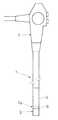
図2は、電子内視鏡を示しており、可撓管からなる挿入部1の基端が操作部2に連結され、挿入部1の先端部分1aには先端ユニット3が着脱自在に連結されている。4は、操作部2からの遠隔操作によって屈曲自在な湾曲部である。
【0019】
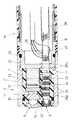
図1は、挿入部1の先端部分1aを示しており、6は、可撓管(湾曲部4を含む)の先端に取り付けられていて、その先側に先端ユニット3が着脱自在に連結される先端口金である。
【0020】
先端ユニット3のブロックを構成するユニット本体7は、例えば電気絶縁性のプラスチックによって形成されていて、その先端面に観察窓8や照明窓9などが配置されている。
【0021】
ユニット本体7の観察窓8の内側には、対物光学系11が内蔵されており、その対物光学系11による被写体の結像面に、例えばCCDからなる固体撮像素子12の撮像面が配置されている。
【0022】
13は、固体撮像素子12が取り付けられた回路基板であり、固体撮像素子12の他にも、固体撮像素子12を駆動するための電子部品(図示せず)などが取り付けられている。
【0023】
照明窓9の部分には、被写体を照明する照明光を伝達するために挿入部1内に挿通配置されたライトガイドファイババンドル28の射出端面が、観察視野方向に向けて配置されている。
【0024】
ユニット本体7は円柱状に形成されていて、挿入部1の先端口金6に対して前方から着脱自在である。ユニット本体7の外周面には、円筒状のフード状部材21が回転自在に被嵌されており、そのフード状部材21と先端口金6とに形成されたネジ部22を螺合させることによって、ユニット本体7が前方から先端口金6に押し付けられた状態で固定される。
【0025】
28aは、ライトガイドファイババンドル28の先端部分を囲んで設けられたパイプ状のライトガイド口金であり、先端口金6から前方に真っ直ぐに突出していて、その基端部は先端口金6に水密に接合固着されている。
【0026】
そして、ユニット本体7側には、ライトガイド口金28aが挿脱自在に嵌合する嵌合孔41が、軸線方向に真っ直ぐにユニット本体7を貫通して穿設されている。
【0027】
28bは、ライトガイド口金28aと先端口金6との固定状態をより確実にするために、先端口金6の前端の壁部を挟むようにライトガイド口金28aに突設された鍔部28bである。
【0028】
ライトガイド口金28aの外周面には、挿入部1内の電気配線26に接続された複数の電気接点25が設けられている。そして、そのライトガイド口金28aが差し込まれるユニット本体7側の嵌合孔41の内周面には、先端ユニット3側の回路基板13上の回路に接続線23を介して接続された複数の電気接点24が、ライトガイド口金28a側の電気接点25と位置を合わせて設けられている。
【0029】
両電気接点24,25は、ユニット本体7の軸線方向と垂直方向にあい対向して配置されている。
挿入部1側の電気接点25は、ライトガイド口金28aの軸線方向に間隔をあけて複数設けられているが、図3は、そのうちの一つの電気接点25が示される状態で、ライトガイド口金28a部分の断面を示している。
【0030】
ライトガイド口金28aは、電気絶縁部材によって形成された内側パイプ28cと、やはり電気絶縁部材によって形成された外側パイプ28dからなる二重パイプ構造になっている。
【0031】
そして、電気接点25は外側パイプ28d部分に形成されていて、電気接点25と先端口金6内の電気配線26とを接続するために軸線方向に長く形成された導電部28eが、内側パイプ28c部分に形成されている。
【0032】
その結果、図1に示されるように、先端ユニット3が挿入部1の先端部分1aに連結された状態では、双方の電気接点24,25が接続されて、固体撮像素子12と挿入部1内の電気配線26との間で信号(撮像信号及びCCD駆動信号など)の伝送が行われる。
【0033】
なお、先端ユニット3を先端口金6に連結する際には、まず、ユニット本体7の嵌合孔41内にライトガイド口金28aを差し込み、その状態からフード状部材21と先端口金6とをネジ部22で螺合させる。ユニット本体7と先端口金6は相対的に回転しない状態に係合しているので、螺合操作の際にユニット本体7が回転してしまうことはない。
【0034】
ネジ部22が螺合するようにフード状部材21を締め込んでいくと、ユニット本体7が、フード状部材21に押されて先端口金6の前端面に押し付け固定された状態になる。
【0035】
そして、フード状部材21と先端口金6とのネジ部22における結合を解いて、先端口金6に対してユニット本体7を前方に引っ張れば、先端ユニット3が先端口金6から外れて、電気接点24,25の接続が外れる。
【0036】
ユニット本体7の先端近傍の外周面には、フード状部材21の内周面に密接するシール用のOリング31が装着されている。また、先端口金6のネジ部22の後端部分には、フード状部材21の口元の内周面に密接するシール用のOリング32が装着されている。ライトガイド口金28aの先端近傍の位置にも、シール用のOリング42が配置されている。
【0037】
その結果、図1に示されるように、挿入部1の先端部分1aに先端ユニット3が連結された状態においては、Oリング31,32,42によるシール効果によって、電気接点24,25部分やネジ部22などに外部の水分が侵入しない。
【0038】
さらにこの実施の形態においては、ゴム製のシール部材47が先端口金6の外周部分にライニングされており、フード状部材21の口元端部がシール部材47に当接することにより、防水効果が高められている。したがって、その内側のOリング32を省略することもできる。
【0039】
このような構成により、先端ユニット3が挿入部1の先端部分1aに取り付けられた使用状態においては、電気接点24,25に水分が付着して信号不良などが発生するおそれがない。なお、フード状部材21と密接する二つのOリング31,32は、ネジ部22の緩み止めの役割も果たしている。
【0040】
また、先端ユニット3は、フード状部材21がユニット本体7に対して回転及び摺動自在であって、ユニット本体7から取り外すことができるが、ユニット本体7の表面部分は全て水密に封止されていて、その内部に外から水分が侵入しないようになっている。したがって、先端ユニット3は、挿入部1から取り外した単体状態で十分に洗浄及び消毒をすることができる。
【0041】
一方、挿入部1の側も、先端ユニット3が取り外された状態において、外部から内部に全く水分が侵入しない防水構造になっている。したがって、この電子内視鏡を検査に使用したら、先端ユニット3を取り外した状態で、挿入部1側(操作部2も含む)をオートクレーブ装置に入れて高圧蒸気による滅菌消毒を行うことができる。
【0042】
そのようにして、先端ユニット3を取り外して滅菌消毒を行えば、固体撮像素子12をオートクレーブ装置内に入れなくて済むので、固体撮像素子12を熱破壊から守ることができる。
【0043】
また、固体撮像素子12が組み込まれた先端ユニット3が挿入部1に対して着脱自在なので、組み立て中や使用中に固体撮像素子12が破損したような場合には、先端ユニット3だけを交換すればよく、挿入部1側には全く手を加える必要がない。
【0044】
なお、図4に示されるように、照明用のライトガイドファイババンドル28が複数設けられている場合には、その各々のライトガイド口金28aに電気接点24,25を配置してもよい(第2の実施の形態)。
【0045】
図5は、本発明の第3の実施の形態を示しており、外周面に電気接点25が配置されたライトガイド口金28aを、先端ユニット3の中心軸線位置に配置したものである。
【0046】
38は処置具挿通チャンネル、39は、処置具挿通チャンネル38に真っ直ぐに連通するようにユニット本体7を貫通して形成された処置具挿通孔である。なお、対物光学系や固体撮像素子の図示は省略されている。
【0047】
このように構成することにより、ユニット本体7が、ライトガイド口金28aを中心にして回転自在となるので、先端口金6と螺合するネジ部22をユニット本体7自体に形成して、フード状部材21を省略することができる。
【0048】
ただし、ユニット本体7が先端口金6に対して常に正しい向きに取り付けられるようにするために、双方のネジ部22のネジ加工を調整して精密なネジ切り加工を行う必要がある。
【0049】
そこでこの実施の形態は、そのような加工の煩雑さを解消するために、先端口金6の外周面に、金属製の調整ナット51を螺合させて、その調整ナット51にユニット本体7が当接するようにしている。したがって、調整ナット51を回転させることによって、先端口金6に対するユニット本体7の固定位置を微調整することができる。
【0050】
なお、この実施の形態においては、先端口金6の外周面に装着されたOリング37は、ネジ部22の緩みを防止するために機能させているので、ライトガイド口金28aの外周面に密接する防水用のOリング42を前後両端部分に設けてある。
【0051】
また、この実施の形態においては、ユニット本体7自体を回転させて、先端口金6に対する係脱をすることができるので、ネジ部22に代えてバヨネット機構を用いて、ユニット本体7と先端口金6とをバヨネット係合させてもよい。
【0052】
なお、本発明は上記の実施の形態に限定されるものではなく、例えば、送気 送水又は吸引などのための流体通過用パイプを先端口金6から前方に突設して、その外周面に電気接点25を設けてもよい。
【0053】
【発明の効果】
本発明によれば、対物光学系と固体撮像素子とが取り付けられたユニットを挿入部の先端部分に外部から着脱自在に構成して、そのユニットが挿入部の先端部分に取り付けられた状態のときに、挿入部の先端から前方に向けて突設された突出部に設けられた電気接点とその突出部が挿通されるようにユニット側に形成された孔に形成された電気接点とが接続されるようにしたことにより、固体撮像素子を含むユニットを挿入部の先端部分から取り外して、固体撮像素子部分だけの交換を容易に行うことができ、また、固体撮像素子を高熱にさらすことなく、電子内視鏡をオートクレーブによって滅菌処理することができる。
【図面の簡単な説明】
【図1】本発明の第1の実施の形態の電子内視鏡の挿入部先端部分の側面断面図である。
【図2】本発明の第1の実施の形態の電子内視鏡の全体略示図である。
【図3】本発明の第1の実施の形態の部分側面断面図である。
【図4】本発明の第2の実施の形態の正面透視図である。
【図5】本発明の第3の実施の形態の電子内視鏡の一部を省略して示す側面断面図である。
【符号の説明】
1 挿入部
1a 先端部分
3 先端ユニット
6 先端口金
7 ユニット本体
12 固体撮像素子
24,25 電気接点
28 ライトガイドファイババンドル
28a ライトガイド口金
41 嵌合孔[0001]
BACKGROUND OF THE INVENTION
The present invention relates to an electronic endoscope in which an endoscopic observation image is picked up by a solid-state imaging device arranged at the tip of an insertion portion.
[0002]
[Prior art]
In an electronic endoscope, generally, an objective optical system and a solid-state imaging device for capturing an image formed by the objective optical system are arranged in a distal end portion main body constituting the distal end of the insertion portion. . A CCD (charge coupled device) is widely used as a solid-state imaging device.
[0003]
[Problems to be solved by the invention]
Endoscopes need to be cleaned and disinfected each time they are used to prevent infection. As disinfection methods, chemical disinfection and ethylene oxide gas sterilization have been widely performed so far.
[0004]
However, if disinfectant solution or ethylene oxide gas remains in the endoscope, it may be harmful to the human body or to sterilize Helicobacter pylori and other viruses that cause gastric ulcers at a higher level. High-pressure steam sterilization (autoclave) has been performed.
[0005]
Autoclaves are non-toxic and safe for the human body, but generally, an object to be sterilized is placed in a high temperature environment of about 120 ° C to 135 ° C.
However, in general, a CCD is often damaged when heated to about 80 ° C. or more due to a difference in thermal expansion coefficient between an adhesive used for assembly and an adherend. For this reason, it has been difficult to sterilize electronic endoscopes using an autoclave.
[0006]
In addition, since the pitch between pixels of the CCD is as small as about 6 to 10 μm, if the discharge occurs in the CCD due to static electricity generated while assembling the endoscope, it causes electrostatic breakdown and becomes a defective product. It may become. In such a case, all endoscopes must be disassembled and reassembled from the beginning.
[0007]
Further, when the endoscope is being used, the tip of the insertion portion may be hit or dropped on the floor, and the impact may damage the CCD. In such a case, it is necessary to replace the entire endoscope or to disassemble and repair the entire endoscope in order to replace the CCD.
[0008]
The present invention has been made to improve the above-described disadvantages, and is an electronic device that can easily replace only the solid-state imaging element portion at the tip and can be sterilized by an autoclave. An object is to provide an endoscope.
[0009]
[Means for Solving the Problems]
In order to achieve the above object, an electronic endoscope according to the present invention is an electronic device in which an objective optical system and a solid-state imaging device for imaging an image formed by the objective optical system are provided at the distal end of the insertion portion. In the endoscope, a unit to which the objective optical system and the solid-state imaging device are attached is configured to be detachable from the outside at the distal end portion of the insertion portion, and a protruding portion protruding forward is provided on the insertion portion. A hole is formed in the unit, and a hole through which the protruding portion is inserted is formed in the unit. When the unit is attached to the distal end portion of the insertion portion, the distal end portion of the insertion portion and the unit An electrical contact connected to transmit an imaging signal or the like between them is arranged in the projecting portion and the hole.
[0010]
Note that a plurality of the electrical contacts may be provided on each of the unit side and the distal end portion side of the insertion portion, and in this case, the plurality of electrical contacts are connected to the outer peripheral surface of the protruding portion and the hole. You may arrange | position with the surrounding surface at intervals in the axial direction.
[0011]
And each said electric contact may be arrange | positioned facing the axial direction and the orthogonal | vertical direction of the said unit.
It should be noted that waterproof means for preventing external moisture from entering at least the electrical contact portion in the state where the unit is attached to the distal end portion of the insertion portion may be provided.
[0012]
In addition, when the unit is removed from the distal end portion of the insertion portion, the distal end portion of the insertion portion should be waterproof so that external moisture does not enter the distal end portion of the insertion portion. The unit itself may have a waterproof structure that prevents external moisture from entering the inside.
[0013]
Further, a plurality of sets of protrusions and holes provided with the electrical contacts may be provided, or the protrusions and holes provided with the electrical contacts are provided at the central axis position of the unit. It may be.
[0014]
A fixing member for fixing the unit to the distal end portion of the insertion portion when the unit is attached to the distal end portion of the insertion portion is detachable with respect to the distal end portion of the insertion portion. It may be a hood-like member.
[0015]
Further, a fixing means for fixing the unit to the distal end portion of the insertion portion when the unit is attached to the distal end portion of the insertion portion may be provided integrally with the unit.
[0016]
The fixing member may be bayonet engaged with the distal end portion of the insertion portion, and the fixing member is screwed with the distal end portion of the insertion portion. Also good.
[0017]
In addition, the light guide for illumination may be penetrated in the said protrusion part, or the fluid passageway may be formed in the said protrusion part.
[0018]
DETAILED DESCRIPTION OF THE INVENTION
Embodiments of the present invention will be described with reference to the drawings.
FIG. 2 shows an electronic endoscope. A proximal end of an insertion portion 1 made of a flexible tube is connected to an
[0019]
FIG. 1 shows a
[0020]
The unit
[0021]
An objective
[0022]
[0023]
In the portion of the illumination window 9, the exit end face of the light
[0024]
The unit
[0025]
28a is a pipe-shaped light guide base provided so as to surround the front end portion of the light
[0026]
On the
[0027]
[0028]
A plurality of
[0029]
Both
A plurality of
[0030]
The
[0031]
The
[0032]
As a result, as shown in FIG. 1, in a state where the
[0033]
When the
[0034]
When the hood-
[0035]
Then, if the
[0036]
A sealing O-
[0037]
As a result, as shown in FIG. 1, in the state where the
[0038]
Further, in this embodiment, the
[0039]
With such a configuration, when the
[0040]
The
[0041]
On the other hand, the insertion portion 1 also has a waterproof structure in which no moisture enters the inside from the outside when the
[0042]
If the
[0043]
Further, since the
[0044]
As shown in FIG. 4, when a plurality of light
[0045]
FIG. 5 shows a third embodiment of the present invention, in which a
[0046]
38 is a treatment instrument insertion channel, and 39 is a treatment instrument insertion hole formed through the
[0047]
With this configuration, the unit
[0048]
However, in order for the unit
[0049]
Therefore, in this embodiment, in order to eliminate the complexity of such processing, a
[0050]
In this embodiment, since the O-
[0051]
Further, in this embodiment, the unit
[0052]
The present invention is not limited to the above-described embodiment. For example, a fluid passage pipe for air supply, water supply, suction, or the like is projected forward from the
[0053]
【The invention's effect】
According to the present invention, when the unit to which the objective optical system and the solid-state imaging device are attached is configured to be detachable from the outside at the distal end portion of the insertion portion, and the unit is attached to the distal end portion of the insertion portion. Are connected to an electrical contact provided in a protruding portion projecting forward from the tip of the insertion portion and an electrical contact formed in a hole formed on the unit side so that the protruding portion is inserted. By doing so, it is possible to remove the unit including the solid-state image sensor from the distal end portion of the insertion portion, and to easily replace only the solid-state image sensor part, and without exposing the solid-state image sensor to high heat, The electronic endoscope can be sterilized by autoclaving.
[Brief description of the drawings]
FIG. 1 is a side sectional view of a distal end portion of an insertion portion of an electronic endoscope according to a first embodiment of the present invention.
FIG. 2 is an overall schematic view of the electronic endoscope according to the first embodiment of the present invention.
FIG. 3 is a partial side cross-sectional view of the first embodiment of the present invention.
FIG. 4 is a front perspective view of a second embodiment of the present invention.
FIG. 5 is a side cross-sectional view showing a part of an electronic endoscope according to a third embodiment of the present invention with a part thereof omitted.
[Explanation of symbols]
DESCRIPTION OF SYMBOLS 1
Claims (10)
Translated fromJapanese上記対物光学系と上記固体撮像素子とが取り付けられたユニットを上記挿入部の先端部分に前方から着脱自在に構成して、照明用のライトガイドを上記挿入部の先端側から前方に向けて突出させると共に、上記ライトガイドが挿通される孔を上記ユニットに形成して、上記ユニットが上記挿入部の先端部分に取り付けられた状態のときに上記挿入部の先端部分と上記ユニットとの間で撮像信号等を伝送するために接続される電気接点を、上記ライトガイドの外周面と上記孔の内周面とに、あい対向して上記ライトガイドの軸線方向に間隔をあけて各々複数個ずつ配置したことを特徴とする電子内視鏡。In an electronic endoscope in which an objective optical system and a solid-state imaging device for capturing an image formed by the objective optical system are provided at the distal end of the insertion portion,
The objective optical system and the solid-state imaging device and is attached unit configured detachably from thefront tip portion of the insertion portion,projecting a light guide for illumination toward the front from the front end side of the insertion portion is allowed Rutotomoni, a hole in which thelight guide is inserted is formed on the unit, the unit is between the tip portion and the unit of the insertion portion in a state attached to the distal end portion of the insertion portion A plurality of electrical contacts connected to transmit an imaging signal, etc., areopposed tothe outer peripheral surface of the light guide andthe inner peripheral surface of the hole witha space inthe axial direction of the light guide. An electronic endoscope characterized by being arranged.
Priority Applications (4)
| Application Number | Priority Date | Filing Date | Title |
|---|---|---|---|
| JP03418597AJP3665441B2 (en) | 1997-02-19 | 1997-02-19 | Electronic endoscope |
| US09/025,632US6095970A (en) | 1997-02-19 | 1998-02-18 | Endoscope |
| GB9803565AGB2322499B (en) | 1997-02-19 | 1998-02-19 | Endoscope |
| DE19806984ADE19806984B4 (en) | 1997-02-19 | 1998-02-19 | endoscope |
Applications Claiming Priority (1)
| Application Number | Priority Date | Filing Date | Title |
|---|---|---|---|
| JP03418597AJP3665441B2 (en) | 1997-02-19 | 1997-02-19 | Electronic endoscope |
Publications (2)
| Publication Number | Publication Date |
|---|---|
| JPH10229969A JPH10229969A (en) | 1998-09-02 |
| JP3665441B2true JP3665441B2 (en) | 2005-06-29 |
Family
ID=12407149
Family Applications (1)
| Application Number | Title | Priority Date | Filing Date |
|---|---|---|---|
| JP03418597AExpired - Fee RelatedJP3665441B2 (en) | 1997-02-19 | 1997-02-19 | Electronic endoscope |
Country Status (1)
| Country | Link |
|---|---|
| JP (1) | JP3665441B2 (en) |
Families Citing this family (2)
| Publication number | Priority date | Publication date | Assignee | Title |
|---|---|---|---|---|
| DE102004009384B4 (en)* | 2004-02-26 | 2005-12-22 | Olympus Winter & Ibe Gmbh | Video endoscopic system |
| JP5384857B2 (en)* | 2008-06-03 | 2014-01-08 | オリンパス株式会社 | Endoscope device |
- 1997
- 1997-02-19JPJP03418597Apatent/JP3665441B2/ennot_activeExpired - Fee Related
Also Published As
| Publication number | Publication date |
|---|---|
| JPH10229969A (en) | 1998-09-02 |
Similar Documents
| Publication | Publication Date | Title |
|---|---|---|
| US6095970A (en) | Endoscope | |
| US9962069B2 (en) | Endoscope with distal hermetically sealed sensor | |
| JP3297033B2 (en) | Endoscope | |
| TWI444171B (en) | Disposable sheath for use with an imaging system | |
| US6019719A (en) | Fully autoclavable electronic endoscope | |
| US5587736A (en) | Sterilizable CCD video camera | |
| JP3665438B2 (en) | Electronic endoscope | |
| US12016527B2 (en) | Video mediastinoscope and a method for its configuration | |
| JP3665443B2 (en) | Endoscope | |
| CN107997732B (en) | Endoscope and have endoscope hose assembly of disposable sleeve | |
| JP3665441B2 (en) | Electronic endoscope | |
| JP7335455B2 (en) | rigid endoscope | |
| JPS59129050A (en) | Endoscope | |
| JP3665442B2 (en) | Electronic endoscope | |
| JP3665440B2 (en) | Electronic endoscope | |
| JP3665439B2 (en) | Electronic endoscope | |
| JPH07327923A (en) | Endoscope system | |
| JP4537514B2 (en) | Endoscope | |
| JP7370474B2 (en) | flexible endoscope | |
| JP3279398B2 (en) | Endoscope imaging device | |
| JPH10229970A (en) | Electronic endoscope | |
| JP2848571B2 (en) | Endoscope device | |
| JP3523666B2 (en) | Endoscope device with endoscope cover system | |
| JP2828296B2 (en) | Endoscope | |
| JP3863788B2 (en) | Endoscope |
Legal Events
| Date | Code | Title | Description |
|---|---|---|---|
| A977 | Report on retrieval | Free format text:JAPANESE INTERMEDIATE CODE: A971007 Effective date:20041124 | |
| A131 | Notification of reasons for refusal | Free format text:JAPANESE INTERMEDIATE CODE: A131 Effective date:20041130 | |
| A521 | Written amendment | Free format text:JAPANESE INTERMEDIATE CODE: A523 Effective date:20050117 | |
| TRDD | Decision of grant or rejection written | ||
| A01 | Written decision to grant a patent or to grant a registration (utility model) | Free format text:JAPANESE INTERMEDIATE CODE: A01 Effective date:20050323 | |
| A61 | First payment of annual fees (during grant procedure) | Free format text:JAPANESE INTERMEDIATE CODE: A61 Effective date:20050401 | |
| R150 | Certificate of patent or registration of utility model | Free format text:JAPANESE INTERMEDIATE CODE: R150 | |
| FPAY | Renewal fee payment (event date is renewal date of database) | Free format text:PAYMENT UNTIL: 20090408 Year of fee payment:4 | |
| FPAY | Renewal fee payment (event date is renewal date of database) | Free format text:PAYMENT UNTIL: 20090408 Year of fee payment:4 | |
| FPAY | Renewal fee payment (event date is renewal date of database) | Free format text:PAYMENT UNTIL: 20100408 Year of fee payment:5 | |
| LAPS | Cancellation because of no payment of annual fees |