JP3665382B2 - Gas desulfurization method with sorbent regeneration - Google Patents
Gas desulfurization method with sorbent regenerationDownload PDFInfo
- Publication number
- JP3665382B2 JP3665382B2JP10762695AJP10762695AJP3665382B2JP 3665382 B2JP3665382 B2JP 3665382B2JP 10762695 AJP10762695 AJP 10762695AJP 10762695 AJP10762695 AJP 10762695AJP 3665382 B2JP3665382 B2JP 3665382B2
- Authority
- JP
- Japan
- Prior art keywords
- sorbent
- gas
- transport
- regenerated
- riser
- Prior art date
- Legal status (The legal status is an assumption and is not a legal conclusion. Google has not performed a legal analysis and makes no representation as to the accuracy of the status listed.)
- Expired - Lifetime
Links
- 239000002594sorbentSubstances0.000titleclaimsdescription176
- 230000008929regenerationEffects0.000titleclaimsdescription47
- 238000011069regeneration methodMethods0.000titleclaimsdescription47
- 238000000034methodMethods0.000titleclaimsdescription31
- 238000006477desulfuration reactionMethods0.000titledescription27
- 230000023556desulfurizationEffects0.000titledescription27
- 239000007789gasSubstances0.000claimsdescription100
- RAHZWNYVWXNFOC-UHFFFAOYSA-NSulphur dioxideChemical compoundO=S=ORAHZWNYVWXNFOC-UHFFFAOYSA-N0.000claimsdescription38
- NINIDFKCEFEMDL-UHFFFAOYSA-NSulfurChemical compound[S]NINIDFKCEFEMDL-UHFFFAOYSA-N0.000claimsdescription37
- 229910052717sulfurInorganic materials0.000claimsdescription37
- 239000011593sulfurSubstances0.000claimsdescription37
- 239000006096absorbing agentSubstances0.000claimsdescription27
- 238000006243chemical reactionMethods0.000claimsdescription15
- QVGXLLKOCUKJST-UHFFFAOYSA-Natomic oxygenChemical compound[O]QVGXLLKOCUKJST-UHFFFAOYSA-N0.000claimsdescription14
- 239000001301oxygenSubstances0.000claimsdescription14
- 229910052760oxygenInorganic materials0.000claimsdescription14
- UCKMPCXJQFINFW-UHFFFAOYSA-NSulphideChemical compound[S-2]UCKMPCXJQFINFW-UHFFFAOYSA-N0.000claimsdescription7
- 230000001172regenerating effectEffects0.000claimsdescription7
- XLOMVQKBTHCTTD-UHFFFAOYSA-NZinc monoxideChemical compound[Zn]=OXLOMVQKBTHCTTD-UHFFFAOYSA-N0.000claimsdescription6
- 230000003134recirculating effectEffects0.000claimsdescription3
- 239000011787zinc oxideSubstances0.000claimsdescription3
- 230000003009desulfurizing effectEffects0.000claimsdescription2
- 238000004064recyclingMethods0.000claims1
- 238000005486sulfidationMethods0.000claims1
- QAOWNCQODCNURD-UHFFFAOYSA-NSulfuric acidChemical compoundOS(O)(=O)=OQAOWNCQODCNURD-UHFFFAOYSA-N0.000description18
- 239000007787solidSubstances0.000description18
- 239000002245particleSubstances0.000description13
- IJGRMHOSHXDMSA-UHFFFAOYSA-NAtomic nitrogenChemical compoundN#NIJGRMHOSHXDMSA-UHFFFAOYSA-N0.000description10
- 238000010521absorption reactionMethods0.000description10
- 239000007800oxidant agentSubstances0.000description10
- 230000001590oxidative effectEffects0.000description10
- 239000003085diluting agentSubstances0.000description9
- 238000000926separation methodMethods0.000description9
- 238000001816coolingMethods0.000description8
- 238000004519manufacturing processMethods0.000description8
- 229910044991metal oxideInorganic materials0.000description8
- 150000004706metal oxidesChemical class0.000description8
- 238000012360testing methodMethods0.000description8
- 238000005243fluidizationMethods0.000description7
- 239000002737fuel gasSubstances0.000description6
- HCHKCACWOHOZIP-UHFFFAOYSA-NZincChemical compound[Zn]HCHKCACWOHOZIP-UHFFFAOYSA-N0.000description5
- 238000010586diagramMethods0.000description5
- 229910052757nitrogenInorganic materials0.000description5
- 229910052725zincInorganic materials0.000description5
- 239000011701zincSubstances0.000description5
- 229910001308Zinc ferriteInorganic materials0.000description4
- 238000010438heat treatmentMethods0.000description4
- 238000001179sorption measurementMethods0.000description4
- WGEATSXPYVGFCC-UHFFFAOYSA-Nzinc ferriteChemical compoundO=[Zn].O=[Fe]O[Fe]=OWGEATSXPYVGFCC-UHFFFAOYSA-N0.000description4
- 238000002474experimental methodMethods0.000description3
- 239000000463materialSubstances0.000description3
- 238000003860storageMethods0.000description3
- QAOWNCQODCNURD-UHFFFAOYSA-LSulfateChemical compound[O-]S([O-])(=O)=OQAOWNCQODCNURD-UHFFFAOYSA-L0.000description2
- RTAQQCXQSZGOHL-UHFFFAOYSA-NTitaniumChemical compound[Ti]RTAQQCXQSZGOHL-UHFFFAOYSA-N0.000description2
- 230000001174ascending effectEffects0.000description2
- 230000015572biosynthetic processEffects0.000description2
- 238000013461designMethods0.000description2
- 238000011161developmentMethods0.000description2
- 230000018109developmental processEffects0.000description2
- 239000000428dustSubstances0.000description2
- 239000012530fluidSubstances0.000description2
- 238000002309gasificationMethods0.000description2
- 229910052751metalInorganic materials0.000description2
- 239000002184metalSubstances0.000description2
- 239000000203mixtureSubstances0.000description2
- 230000004048modificationEffects0.000description2
- 238000012986modificationMethods0.000description2
- 230000003647oxidationEffects0.000description2
- 238000007254oxidation reactionMethods0.000description2
- 239000012071phaseSubstances0.000description2
- 238000010926purgeMethods0.000description2
- XLYOFNOQVPJJNP-UHFFFAOYSA-NwaterChemical compoundOXLYOFNOQVPJJNP-UHFFFAOYSA-N0.000description2
- 235000008733Citrus aurantifoliaNutrition0.000description1
- 235000011941Tilia x europaeaNutrition0.000description1
- 238000009825accumulationMethods0.000description1
- 230000015556catabolic processEffects0.000description1
- 239000003054catalystSubstances0.000description1
- 239000003034coal gasSubstances0.000description1
- 238000007796conventional methodMethods0.000description1
- 239000000498cooling waterSubstances0.000description1
- 230000002950deficientEffects0.000description1
- 238000006731degradation reactionMethods0.000description1
- 238000010790dilutionMethods0.000description1
- 239000012895dilutionSubstances0.000description1
- 238000009826distributionMethods0.000description1
- 230000000694effectsEffects0.000description1
- 238000005485electric heatingMethods0.000description1
- 238000009472formulationMethods0.000description1
- 239000002803fossil fuelSubstances0.000description1
- 230000020169heat generationEffects0.000description1
- 239000001257hydrogenSubstances0.000description1
- 229910052739hydrogenInorganic materials0.000description1
- 125000004435hydrogen atomChemical class[H]*0.000description1
- 229910001026inconelInorganic materials0.000description1
- 239000004571limeSubstances0.000description1
- 229910052976metal sulfideInorganic materials0.000description1
- 238000002156mixingMethods0.000description1
- 238000011017operating methodMethods0.000description1
- 238000013021overheatingMethods0.000description1
- 229920003023plasticPolymers0.000description1
- 238000004321preservationMethods0.000description1
- 238000011165process developmentMethods0.000description1
- 238000012545processingMethods0.000description1
- 238000011084recoveryMethods0.000description1
- 238000012827research and developmentMethods0.000description1
- 229920006395saturated elastomerPolymers0.000description1
- 239000007790solid phaseSubstances0.000description1
- 239000002910solid wasteSubstances0.000description1
- 239000000126substanceSubstances0.000description1
- 150000003464sulfur compoundsChemical class0.000description1
- 238000003786synthesis reactionMethods0.000description1
- 229910052861titaniteInorganic materials0.000description1
- 238000012546transferMethods0.000description1
Images


Landscapes
- Treating Waste Gases (AREA)
- Separation Of Gases By Adsorption (AREA)
- Gas Separation By Absorption (AREA)
Description
Translated fromJapanese【0001】
【産業上の利用分野】
本発明は、再生可能な収着剤を用いた流動床脱硫方法、一層詳しくは収着剤再生オフガスが硫酸製造又は硫黄への還元に適した二酸化硫黄濃度を有する流動床脱硫方法に関する。
【0002】
【従来の技術】
亜鉛系金属酸化物収着剤を用いた流動床脱硫は当分野で知られている。典型的には、化石燃料のガス化により生成した燃料ガスは硫黄化合物を含み、それら化合物はその燃料ガスを用いる前に除去しなければならない。硫黄を奇麗に除去するためには、硫黄含有燃料ガスを粒状金属酸化物収着剤と高い温度で接触させる。これらの気・固相反応装置は、従来固定又は流動床反応器を用いている。硫黄と収着剤との反応により燃料ガスを脱硫し、使用済み硫化収着剤を生ずる。次に使用済み収着剤を、酸化剤ガス、例えば空気と高い温度で反応させ、二酸化硫黄含有オフガスを生成させることにより再生し、硫黄吸収に再使用する。オフガスは次に石灰と反応させて硫酸塩を形成させ、硫黄の除去を完成させるのが典型的なやり方である。
【0003】
金属酸化物収着剤は高い温度では摩耗を受け、化学的及び物理的収着剤構造が劣化することが知られている。吸収・再生工程を繰り返すことにより過度の収着剤劣化が起きるのを回避するため、硫黄吸収及び収着剤再生反応の反応温度は、一般に約650℃〜760℃より低く保持しなければならない。硫黄吸収反応温度の制御は一般には問題にならない。なぜなら、硫黄吸収反応は僅かな量の熱しか発生しないからである。しかし、再生反応温度の制御は、硫黄再生反応が高度に発熱的なので一層困難である。収着剤を損傷することがある過度の再生反応温度にならないようにするため、再生反応速度を限定しなければならない。一般にこのことは、発生した熱を吸収させるため酸化剤ガス中に窒素及び(又は)水蒸気のような希釈剤ガスを使用し、酸化剤(酸素)濃度を低くするか、収着剤冷却器を用いるか、又はその両方の組合せを用いることを必要とする。
【0004】
収着剤再生に希釈剤ガスを用いることには幾つかの欠点がある。希釈剤ガスは再生反応器の処理体積量を増大する。連続した再生器の容器の大きさは、希望の滞留時間を維持するためには増大しなければならない。オフガスの二酸化硫黄濃度は余りにも低くなり、硫酸の製造及び(又は)硫黄の還元のような付加価値のある用途に更に用いることができなくなる。収着剤冷却器を用いるのは、それによって資本コストが更に大きくなるため望ましくない。
【0005】
【発明が解決しようとする課題】
収着剤再生方式で希釈剤又は収着剤冷却に対する必要性を実質的に減少させるか又は皆無にし、硫酸製造及び(又は)硫黄の還元で用いるのに適した二酸化硫黄濃度を有するオフガスを生成するやり方で、亜鉛系金属酸化物による脱硫方法を操作するのが有利であろう。
【0006】
アイアラ(Ayala)その他による「移動床用高温脱硫収着剤の耐久性の改良」(Enhanced Durability of High-Temperature Desulfurization Sorbents for Moving-Bed Applications )〔1992年5月、ニューヨーク、スケネクタディ、GE・コーポレート・リサーチ・アンド・ディベロプメント(Corporate Research and Development), DE-AC21-88MC25003 〕には、化学的に活性で機械的に耐久性のある亜鉛フェライト及びチタン酸亜鉛収着剤配合物の開発が記載されており、それらは移動床高温石炭ガス脱硫法に適している。
【0007】
モルガンタウン・エネルギー・テクノロジー・センター(Morgantown Energy Technology Center)による「流動床高温ガス脱硫法開発装置」(Fluid-Bed Hot-Gas Desulfurization Process Development Unit)〔U.S.デパートメント・オブ・エネルギー(Department of Energy)〕には、吸収器と再生器との間にチタン酸亜鉛、亜鉛フェライト又は他の物質の如き脱硫収着剤の連続的循環を含む総合ガス化併合工程(IGCC)系で流動床高温ガス脱硫(HGD)法開発装置(PDU)を使用することが記載されている。吸収器では、燃料ガス流から硫黄物質を除去する結果として収着剤が硫化される。再生器では、その硫化された収着剤に捕捉された硫黄が空気で酸化され、収着剤の活性度を回復し、SO2を生ずる。
【0008】
【課題を解決するための手段】
本発明の脱硫方法の収着剤再生段階へ脱硫段階から供給される使用済み収着剤の硫黄含有量を限定することにより、収着剤再生段階での反応速度及び温度上昇を、希釈剤ガス又は収着剤冷却を用いることなく、実質的に制御することができる。例えば、硫酸製造及び(又は)硫黄への還元で有用な化学量論濃度に近い二酸化硫黄を含有するオフガスを生成させることができる。更に、再生工程での温度上昇が減少することにより、収着剤性能寿命を増大し、収着剤在庫を減少させることができる。これに対し従来法では、オフガスの二酸化硫黄濃度は余りにも薄く、硫酸製造には用いられないのが典型的である。その代わり、そのようなガスは通常洗浄され、廃棄しなければならない固体廃棄物を生ずる。
【0009】
一つの態様として、本発明は、ガスを脱硫し、収着剤を再生する方法を与える。一つの工程として、供給ガスを粒状金属酸化物収着剤で輸送上昇管(Transport riser)中で脱硫して硫化物含有量が減少した流出ガスを形成する。別の工程として部分的に硫化した収着剤を流出ガスから分離して本質的に収着剤粒子を含まない生成物ガス流を形成する。その硫化した収着剤を酸素含有ガスと接触させることにより再生して二酸化硫黄含有再生オフガスを形成する。再生オフガスから再生収着剤を分離し、実質的に前記収着剤を含まないオフガス流を形成する。再生された収着剤を脱硫工程へ再循環する。部分的に硫化した収着剤は、好ましくは5重量%より少ない硫黄を含み、一層好ましくは約1〜約2重量%の硫黄を含む。再生オフガスは、約10モル%以上、約15モル%の化学量論的濃度までの二酸化硫黄を含むのが好ましい。再生工程は再生輸送上昇管で行うのが好ましい。脱硫及び再生工程は、収着剤、各供給物、及び再生ガスについて1回の通過で行うことができる。別法として、部分的に硫化された収着剤の第一部分を脱硫工程へ再循環し、第二部分を再生工程へ供給してもよい。もし望むならば、その方法は収着剤冷却工程を含んでいてもよい。再生工程中の再生ガスの温度上昇は約140から約195℃(約250から約350°F)であるのが好ましい。
【0010】
別の態様として、本発明は、脱硫装置を与える。その装置は、硫化物を含む供給ガスを粒状金属酸化物収着剤と混合して接触させ、硫化物含有量が減少した流出ガスを生成させるために用いる輸送上昇管を有する。流出ガスから部分的に硫化した収着剤を回収し、本質的に収着剤粒子を含まない生成物ガス流を形成するために、第一分離領域を用いる。部分的に硫化した収着剤と酸素含有ガスとを収着剤再生条件で接触させ、前記収着剤を再生し、二酸化硫黄含有オフガスを形成するために、再生容器を用いる。オフガスから再生収着剤を回収し、本質的に収着剤粒子を含まない再生オフガス流を形成するために第二分離領域を用いる。この装置は、第二分離領域から回収された再生収着剤を輸送上昇管へ移動させるための導管及び輸送上昇管、再生容器、及び分離領域を実質的に連続的に操作するための金属酸化物収着剤の導入(charge) を有する。
【0011】
脱硫装置の再生容器は、硫化された収着剤と酸素含有ガスとを混合し、反応領域中で輸送流体力学的(transport hydrodynamic) 条件でその収着剤を再生するための輸送上昇管を具えているのが好ましい。収着剤移送導管が、第一分離領域から再生容器へ、また第二分離領域から脱硫輸送上昇管へ、その再生容器及び脱硫上昇管を1回通過方式で操作するために含まれているのが好ましい。
【0012】
別法として、脱硫装置は、部分的に硫化した収着剤を第一分離領域から受け取るための滞留領域、その滞留領域から収着剤の第一部分を脱硫輸送上昇管へ再循環するための導管、及び滞留領域からの収着剤の第二部分を再生容器へ移動させるための導管を有するのが好ましい。輸送管中の再生された収着剤を脱硫上昇器へ空圧式で送るために、還元性ガス源が含まれているのが好ましい。もし望むならば、再生された収着剤を冷却するために熱交換器を含ませることができる。
【0013】
別の態様として、本発明は、上で述べた脱硫装置にガスを供給し、その装置を供給ガスから硫化物を除去して二酸化硫黄を含有するオフガスを生成するように操作する工程を含むガス脱硫方法を与える。酸素含有再生ガスは、希釈されていない空気からなるのが好ましく、オフガスは15〜18モル%の二酸化硫黄を含むのが好ましい。
【0014】
【本発明の詳細な説明】
本発明の脱硫方法の脱硫器段階での収着剤の硫黄収着量は、続く収着剤再生段階の反応速度を制御し、収着剤再生器で過度に温度上昇が起きないようにするため、飽和濃度より充分低い水準に限定する。
【0015】
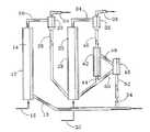
図1〜3に関し、そこでは同じ番号は同様な部品を示しているが、輸送硫黄吸収/再生装置は、入って来るガスと収着剤の両方が唯1回通過する揚力上昇管(lift riser)として操作される上昇管14を有する輸送吸収器12を具えている。上昇管14中では、供給管16を通って導入されたH2S含有ガスを、導管18を通って導入された硫黄収着剤粒子と接触させる。吸収器12は輸送流体力学的範囲で、好ましくは導管16内の供給ガスの圧力及び温度で作動する。
【0016】
金属収着剤によるH2Sの吸収は、金属硫化物及び水を形成する結果になる。この反応は典型的には熱発生量が少なく、収着剤供給速度を、吸収器上昇管14中への再循環量を限定することと組合せて、1回通過当たりの収着剤への硫黄収着率が比較的低くなるように、充分大きくすることができる。1回の通過当たりの収着剤硫黄収着率は、収着剤の5重量%未満であるのが好ましく、一層好ましくは収着剤の約1〜約2重量%である。
【0017】
取り込まれた収着剤粒子を含む脱硫されたガスは、吸収器上昇管14から導管20を通って気体・固体分離器22(一般にサイクロン分離器)中へ送る。実質的に収着剤を含まない脱硫された生成ガスは、導管24を通って取り出す。分離された収着剤粒子は、導管26を通って輸送再生器28へ流れる。再生器28は上昇管30を有し、その中で収着剤上に収着された正味の硫黄が、導管32を通って導入された供給酸化剤(一般に空気+希釈剤)によって二酸化硫黄へ酸化される。取り込まれた再生収着剤粒子を含む二酸化硫黄オフガスは、再生上昇管30から導管34を通り気体・固体分離器36(一般にサイクロン分離器)へ送る。実質的に粒子を含まない二酸化硫黄オフガスは導管38を通って取り出し、回収及び(又は)何かに更に利用し、例えばサルフェーター(sulfator)での使用及び(又は)硫酸の合成のために用いる。分離器36で回収された再生収着剤粒子は、導管40を通って緻密相直立パイプ(dense-phase standpipe)42中へ送り、導管44及び50を通って再生器28へ再循環する。
【0018】
再生は高度の発熱反応であり、もし望むならば、収着剤冷却器46、供給酸化剤中の希釈剤ガス、又はそれらの組合せのような手段により熱を除去することができる。図1〜2で分かるように、直立パイプ42からの収着剤の一部を導管48を通って収着剤冷却器46へ循環し、導管50を通り、直立パイプ42及び導管44からの再循環収着剤と一緒に、収着剤に対し希望の温度を維持するのに充分な物質(mass) 再循環速度で送る。冷却された再生収着剤の一部を収着剤冷却器から導管52を通って取り出し、前に述べたように導管18を通って吸収器12へ再循環する。再循環収着剤は、還元性ガス、例えば水素を含有するガス、又は生成物ガスの後流(slipstream)により吸収器12へ輸送し、収着剤中に残留する硫酸塩と反応させるのが典型的である。プラグ弁54又は同様な型の制御/遮断弁によって、脱硫装置10中の収着剤循環速度を制御する。
【0019】
図2から分かるように、本発明は、吸収器12中への収着剤再循環を組み込むことができる。サイクロン分離器22で生成物ガスから分離された部分的に硫酸塩化された収着剤粒子を、導管102を通って緻密相直立パイプ104中へ送り、導管106を通って吸収器12へ再循環する。導管106中の収着剤粒子の一部分、典型的には少量を、固体(solids)弁110のような手段により導管108を通って輸送再生器28へ分流する。
【0020】
図3に関し、再生器収着剤再循環及び冷却を用いずに、貫流式揚力上昇管(once-through lift riser)のような輸送再生器28を操作することができる。導管202を通って吸収器直立パイプ104から出てきた部分的に硫酸塩化された収着剤の概ね少量部分を、導管204を通って再生器28へ分流する。固体プラグ弁206又は同様なものを用いて再生器28への収着剤供給速度を制御する。分離器36中でSO2オフガスから回収された部分的に再生された収着剤粒子は、導管208を通過し、導管202中の再循環収着剤と一緒にされ、導管210を通って一緒に吸収器12へ送られる。
【0021】
吸収器12から再生器28へ分流する収着剤の量は供給ガスの硫黄含有量及び収着剤の収着量の関数であり、吸収器12中に導入された硫黄平衡量が高くなる程収着剤の分流量は少なくなる結果になるが、再生発熱量は増大する。しかし、約55〜85℃(100〜150°F)の得られる発熱量が、希望する収着剤再生温度の最大値を越えないように、再生器28中での1回の通過当たりの酸化増大量に対応する速度まで、吸収器12からの収着した収着剤の分流量を増大することにより、再生器28は貫流型揚力上昇器として操作することができる。1回通過型上昇器として再生上昇器30を操作することにより、収着剤冷却器46の必要性をなくし、丁度酸化剤に対する上昇器輸送ガス必要量を最小にすることができる。使用済み収着剤の分流量を増大することは、収着剤収着量を低い水準、例えば収着剤の約1〜2重量%の硫黄になる水準に保つことを必要とする。更に、酸化剤の酸素含有量を酸素不足状態に維持するのが好ましい。その結果、収着剤は決して飽和することもなく、完全に再生されることもない。
【0022】
本発明の脱硫、特に1回通過型再生である図3の態様の利点は、気泡発生及び乱流操作方式と比較して容器の直径が小さくてよく、収着剤の寿命が長く、収着剤在庫(inventory)を少なくし、収着剤の冷却及び希釈剤の添加を実質的に除くことができることである。更に、過度の希釈剤添加を避けることにより、導管38中のオフガスは、硫酸製造に適した比較的大きな二酸化硫黄濃度(16〜17%程の高いSO2濃度)を持つことができる。
【0023】
吸収器12は、金属酸化物収着剤を用い、反応器操作方式〔例えば、気泡発生床、高速床(fast bcd)、及び空気輸送〕に依存する圧力で燃料ガスから硫化物を吸収するのに適した温度で操作される。吸収器は一般に約500℃〜約600℃の温度及び約2000kPaまでの周囲圧力で操作される。再生器は最高収着剤作動温度よりも低い温度で操作される。再生器は700℃より低い温度及び吸収器圧力と同様な圧力に維持される。
【0024】
本発明の流動床硫黄吸収器及び収着剤再生器は、気泡発生床、高速床、空気輸送等を含めた流動床操作方式のいずれかで操作することができる。床の粒径及び反応器中の流体速度を含めた操作方式の差は当分野でよく知られている。図1〜3で分かるように、輸送操作方式が好ましい。
【0025】
硫酸プラントへの供給ガスは、約12%の二酸化硫黄を含むのが望ましい。典型的には、空気又は水蒸気希釈を用いず、再生器28の化学量論的に近い操作により、導管38中にほぼ15体積%のSO2を含むオフガス流を生成する。硫酸製造に適したSO2濃度を有するオフガスを導管38中に生ずるのに充分な量で、酸化剤に空気及びいずれかの希釈剤ガスを添加することができる。
【0026】
本発明の脱硫装置の設計の基礎は、脱硫されたガス中のH2Sが20〜30ppmより少なくなるようにするのが好ましい。金属酸化物触媒は、酸化亜鉛、亜鉛フェライト、亜鉛チタナイト(titanite)等又はそれらの組合せからなるのが好ましい。
【0027】
本発明を更に次の実施例により例示する。
【0028】
【実施例】
本発明による、固くて耐久性のある固体状で、亜鉛フェライトと同様な硫黄吸収能力を有する酸化亜鉛系収着剤を用いて硫黄の吸収/再生に対する流動床反応器の適合性及び性能を示すため、輸送流動床反応器試験装置(TRTU)を用いた。他の収着剤の性質には、1.0g/ccの嵩密度、1.6g/ccの真の密度が含まれていた。使用前及び使用後の収着剤粒径分布を表1に与える。
【0029】
【表1】
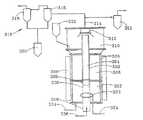
TRTUの一般化した工程図を図4に示す。TRTUは内部反応領域304を有する中心上昇管302を有する。上昇管302は、環状収着剤蓄積領域308を形成する直立パイプ306によって囲まれている。上昇管302の出口の所にある収着剤分離領域310は、生成物ガスから流動化された収着剤を慣性衝突板(inertial strike plate) 312によって分離する。生成物ガスは分離領域310から導管314を通って取り出し、慣用的手段(図示されていない)により分析する。サイクロン分離器318を有する集塵領域316を用いて生成物ガスから残留収着剤を更に分離する。収集した収着剤は保持容器320か又は保存ホッパー321中に保存する。
【0031】
上昇管302の入口の所の収着剤流動化領域322に収着剤の流動床を設置する。収着剤は流動化用ガスにより流動化され、そのガスは散布ガス導管324の出口の所にある散布器323により流動化領域322中へ散布する。このようにして流動化された収着剤を、エダクタ(edactor)326により上昇管302の入口中へ注入する。出口の所に可変円錐弁330を有する導入管328により供給ガスを装置300中へ供給する。供給ガスもエダクタ326への放出ガスとして働く。エダクタ326は、上昇管302を通るガスの速度を制御するように調節することができる。
【0032】
装置300は、収着剤供給ホッパー332、流出管334、及び供給ガス導入導管336を有する。その装置は、直立パイプ306を取り巻く電気加熱装置338、上昇管302上の冷却水ジャケット(図示されていない)、及び予備供給ガス導管(図示されていない)を有する。
【0033】
二つの異なっているが同様な構造を持つ反応器モデルを建造した。低温流動モデルを透明プラスチックから作った。低温流動モデルは、収着剤の空気中での流動化を観察できるように設計した。低温流動モデルは加熱用ジャケット及び上昇管冷却ジャケットを持っていなかった。パージ、流動化、及び試験(放出)ガスは圧搾空気であった。低温流動モデルは、高さが7.01m(23ft)で、上昇管流動領域が1.30cm2(0.0014ft2)である上昇管302を持っていた。直立パイプ306の環状流動領域は、36.23cm2(0.039ft2)であった。更に、低温流動反応器は、循環する固体を蓄積し、上昇管中のガスに対する固体のスリップ(slip)を決定するため、収着剤蓄積領域308(直立パイプ環状部)の真ん中に取付けられた遮断弁(図示されていない)を持っていた。
【0034】
高温操作に適した高温流動モデルを、インコネル800HTで作った。高温流動モデルは、輸送反応器中での硫黄吸収を示すことができるように設計した。高温流動モデルは、加熱用部材の六つの領域を有する加熱用ジャケット338、上昇管、予備流動導管(図示されていない)を持っていた。高温流動反応器は環状遮断弁を持っていなかった。高温流動反応器は、高さが9.14m(30ft)、上昇管流動領域が1.95cm2(0.0021ft2)である上昇管302を持っていた。直立パイプ306の環状流動領域は41.99cm2(0.0452ft2)であった。パージ及び流動化用ガスは圧縮窒素であった。導入試験ガスは、8体積%までのH2S及び残余の窒素を含む圧縮ガス混合物であった。
【0035】
固体供給ホッパー332から使用済み収着剤を供給し、供給導管336から窒素で希釈された空気からなる供給酸化剤を供給することにより、高温流動反応器を収着剤再生のために再構成した。
【0036】
高温排出ガス(吸収又は再生の両方について)のH2S及びSO2濃度水準の両方を決定するために、ドレーガー(Draeger)管を用いた。収着剤再生中の酸素素通りを検出するため、オンラインにGCを設置した。
【0037】
実施例1
上で(低温流動装置で)記述した流動床反応器装置300の低温流動試験を行い、高温流動試験で(高温流動装置で)用いて成功を収める収着剤流動化特性を評価した。
【0038】
約4.55kg(10ポンド)の収着剤を、固体の循環を開始する前に環状部中へ導入した。上昇管中を流れる放出用空気を4.6m/秒(15ft/秒)に設定し、それは実際に2.7m3/時(75ACFH)に相当していた。流動化用空気は約0.06m/秒(0.2ft/秒)に制御した。これによってその環状部中約127cm(50インチ)の固体床高さを生じた。対応する固体循環は113.6kg/時(250ポンド/時)であることが測定された。平均上昇管床密度は約96.1kg/m3(6ポンド/ft3)であった。次に、更に5kg(11ポンド)の収着剤を環状部に添加し、固体床高さを266.7cm(105インチ)まで上昇させた。このようにして固体循環を268.2kg/時(590ポンド/時)まで上昇させ、平均上昇管床密度を200.1kg/m3(12.5ポンド/ft3)まで上昇させた。
【0039】
上で述べたような固定環状部及び上昇管ガス速度を用いた輸送操作方式では、平均上昇管床密度及び固体循環速度は環状部床高さに正比例する。4.5時間の輸送方式実験で、固体キャリオーバー(carryover)率は0.4重量%であることが判明した。
【0040】
低温流動反応器を気泡発生床方式で操作し、環状部中の全固体を9.1kg(20ポンド)に固定して、流動化ガス速度の関数として気泡発生床高さを測定した。エダクタ弁を解放した時、及びエダクタ弁を閉じた時の結果を表2に与える。気泡発生床は、エダクタ弁を閉じた時に同じガス速度で一層大きく拡大した。4.5時間の気泡発生床方式の実験では、固体キャリオーバー率は1.87重量%であることが判明した。
【0041】
【表2】
安定で均一な床特性を考慮すると、反応器及び収着剤は輸送床脱硫用途で用いるのに適していると考えられる。
【0043】
実施例2
上で(高温流動装置で)記述したTRTUの高温流動操作を、低温流動試験によって確立されたパラメーターを用いて行なった。圧力及び流量計の試験に続き、反応器を540℃(1000°F)に加熱し、0.69MPa(絶対圧)(100psia)まで加圧し、15.45kg(34ポンド)の収着剤を導入した。上昇管温度を540℃〜570℃(1000°F〜1050°F)に制御した。上昇管ガス速度を、主に最低2秒間のガス・収着剤接触時間を必要とする条件により決定して4.6m/秒(15ft/秒)に設定した。流動化ガス速度は約0.05m/秒(0.175ft/秒)に維持した。
【0044】
最初、装置を収着剤の循環を行わずに(即ち、エダクタ弁を閉鎖して)操作し、上昇管の壁を予め硫化した。この予備硫化期間中500ppmのH2Sを上昇管中へ導入し、装置出口ではH2Sは検出されなかった。予備硫化期間は約7時間継続した。上昇管出口近くの位置からとったガス試料は、360ppmのH2S濃度を有し、それは希釈することを目的の中に入れる場合の供給物硫黄の原因になっている。試験装置を安定化するため更に1時間経過した後、エダクタ弁を6回転開け、収着剤の循環を開始した。上昇器出口床密度を、144kg/m3(9ポンド/ft3)〜240kg/m3(15ポンド/ft3)に維持した。実験中、装置は、気泡発生床方式の場合の5時間を除き、主に輸送方式で操作した。供給物ガス中のH2S濃度は、最初の2000ppmから終り近くの8000ppmまで変化し、収着剤の飽和を早めた。表3は操作記録を要約したものである。収着剤循環を用いた全実験時間は約42時間であった。
【0045】
素通りが起きるH2S濃度は2700ppmであり、収着剤硫黄含有量は15.4重量%であった。
【0046】
実施例3
実施例2で生成した使用済み収着剤を、再生酸化剤ガスとして窒素で希釈した空気を用い、TRTUで再生した。操作圧力は0.45MPa(絶対圧)(65psia)であり、床温度は620℃〜680℃(1150°F〜1250°F)に維持した。上昇管ガス速度は4.6m/秒(15ft/秒)に設定したままであり、流動化ガス速度は約0.05m/秒(0.175ft/秒)に設定したままであった。上昇管出口床温度は約160kg/m3(10ポンド/ft3)であった。流出ガス中の酸素を検出監視するためオンラインGCを用いた。装置が定常状態に達した直後に収着剤の再生を開始した。最初収着剤が過熱しないようにするため、空気の酸素含有量を、再生工程の最初の2時間同じ間隔で2から10体積%へ次第に増大させ、次に残りの2.5時間は10体積%に維持した。再生中、上昇管流出物中のSO2含有量は、ドレーガー管により分析して、0.8から3.0体積%へ徐々に増大した。SO2濃度は3.75体積%でピークになり、次に3.55体積%へ低下し、然る後、酸素は9.95体積%の濃度水準で輸送床を素通りした。再生後の収着剤中の硫黄含有量は0.15重量%であった。
【0047】
【表3】
本発明の輸送反応器設計は、固定床反応器よりも、遥かに少ない収着剤を用い、単位断面積当たり遥かに大きな生産量を扱っている。更に、540℃で1〜2秒の気体・収着剤接触時間を用いるだけで、平衡H2S漏洩を1ppmvより少なくするのに充分であることが明らかになった。
【0049】
本発明についての上の記述はそれを例示及び説明するためのものである。用いた材料、装置及び特定の部品についての種々の変更が当業者には思い付くであろう。そのような変更は全て特許請求の範囲及びその本質内に入るものである。
【図面の簡単な説明】
【図1】収着剤再循環及び冷却を含めた輸送収着剤再生器及び貫流上昇器(once- through riser)を用いた輸送硫黄吸収器を有する本発明の流動床脱硫器の概略的工程図である。
【図2】輸送吸収器中での収着剤再循環を含む本発明の流動床脱硫器の別の態様の概略的工程図である。
【図3】収着剤再生器が収着剤冷却を用いない貫流揚力上昇器を有する場合の、本発明の流動床脱硫器の別の態様の概略的工程図である。
【図4】本発明の方法の有用性を示すため実施例で用いた小型輸送流動床硫化収着剤吸収器/再生器の概略的工程図である。
【符号の説明】
12 吸収器
14 上昇管
16 供給導管
22 気体・固体分離器
28 再生器
30 再生上昇管
36 分離器
42 直立パイプ
46 収着剤冷却器
104 吸収器直立パイプ
302 中心上昇管
304 内部反応領域
306 直立パイプ
308 環状収着剤蓄積領域
316 集塵領域
318 サイクロン分離器
320 保持容器
321 保存ホッパー
322 収着剤流動化領域
326 放出器(エダクタ)
338 電気加熱装置[0001]
[Industrial application fields]
The present invention relates to a fluidized bed desulfurization method using a renewable sorbent, and more particularly to a fluidized bed desulfurization method in which the sorbent regeneration off-gas has a sulfur dioxide concentration suitable for sulfuric acid production or reduction to sulfur.
[0002]
[Prior art]
Fluid bed desulfurization using zinc-based metal oxide sorbents is known in the art. Typically, the fuel gas produced by fossil fuel gasification contains sulfur compounds that must be removed before the fuel gas can be used. In order to remove sulfur cleanly, the sulfur-containing fuel gas is brought into contact with the particulate metal oxide sorbent at an elevated temperature. These gas / solid phase reactors conventionally use fixed or fluidized bed reactors. The reaction of sulfur with the sorbent desulfurizes the fuel gas, producing a used sulfurized sorbent. The spent sorbent is then regenerated by reacting with an oxidant gas, such as air, at an elevated temperature to produce a sulfur dioxide-containing offgas and reused for sulfur absorption. The off-gas is then typically reacted with lime to form sulfate, completing the sulfur removal.
[0003]
It is known that metal oxide sorbents are subject to wear at high temperatures and the chemical and physical sorbent structures are degraded. In order to avoid excessive sorbent degradation due to repeated absorption and regeneration steps, the reaction temperature of the sulfur absorption and sorbent regeneration reaction must generally be kept below about 650 ° C to 760 ° C. Control of the sulfur absorption reaction temperature is generally not a problem. This is because the sulfur absorption reaction generates only a small amount of heat. However, the control of the regeneration reaction temperature is more difficult because the sulfur regeneration reaction is highly exothermic. In order to avoid excessive regeneration reaction temperatures that can damage the sorbent, the regeneration reaction rate must be limited. In general, this means using a diluent gas, such as nitrogen and / or water vapor, in the oxidant gas to absorb the generated heat, reducing the oxidant (oxygen) concentration, or using a sorbent cooler. Use, or a combination of both.
[0004]
There are several disadvantages to using diluent gas for sorbent regeneration. Diluent gas increases the processing volume of the regeneration reactor. The size of the continuous regenerator vessel must be increased to maintain the desired residence time. The off-gas sulfur dioxide concentration is too low to be used further in value-added applications such as sulfuric acid production and / or sulfur reduction. The use of a sorbent cooler is undesirable because it adds to the capital cost.
[0005]
[Problems to be solved by the invention]
The sorbent regeneration process substantially reduces or eliminates the need for diluent or sorbent cooling and produces an off-gas with a sulfur dioxide concentration suitable for use in sulfuric acid production and / or sulfur reduction. In this way, it would be advantageous to operate the desulfurization process with zinc-based metal oxides.
[0006]
"Improved Durability of High-Temperature Desulfurization Sorbents for Moving-Bed Applications" by Ayala et al. (May 1992, New York, Schenectady, GE Corporate, Corporate Research and Development, DE-AC21-88MC25003) describes the development of chemically active and mechanically durable zinc ferrite and zinc titanate sorbent formulations. They are suitable for moving bed hot coal gas desulfurization process.
[0007]
"Fluid-Bed Hot-Gas Desulfurization Process Development Unit" by the Morgantown Energy Technology Center (US Department of Energy) ] In a fluidized bed hot gas desulfurization in an integrated gasification combined process (IGCC) system involving continuous circulation of desulfurization sorbents such as zinc titanate, zinc ferrite or other materials between the absorber and the regenerator. The use of (HGD) method development equipment (PDU) is described. In the absorber, the sorbent is sulfided as a result of removing sulfur material from the fuel gas stream. In the regenerator, the sulfur trapped in the sulfurized sorbent is oxidized by air to restore the sorbent activity and the SO2 Is produced.
[0008]
[Means for Solving the Problems]
By limiting the sulfur content of the used sorbent supplied from the desulfurization stage to the sorbent regeneration stage of the desulfurization method of the present invention, the reaction rate and temperature increase in the sorbent regeneration stage can be reduced. Or it can be controlled substantially without the use of sorbent cooling. For example, off-gas containing sulfur dioxide close to the stoichiometric concentration useful in sulfuric acid production and / or reduction to sulfur can be produced. In addition, a decrease in temperature rise in the regeneration process can increase sorbent performance life and reduce sorbent inventory. In contrast, in the conventional method, the off-gas sulfur dioxide concentration is too thin and is typically not used for sulfuric acid production. Instead, such gases are usually cleaned, resulting in solid waste that must be discarded.
[0009]
In one embodiment, the present invention provides a method for desulfurizing gas and regenerating the sorbent. As one step, the feed gas is desulfurized with a particulate metal oxide sorbent in a Transport riser to form an effluent gas with reduced sulfide content. As a separate step, the partially sulfurized sorbent is separated from the effluent gas to form a product gas stream that is essentially free of sorbent particles. The sulfurized sorbent is regenerated by contacting it with an oxygen-containing gas to form a sulfur dioxide-containing regenerated off-gas. The regenerated sorbent is separated from the regenerated offgas to form an offgas stream substantially free of the sorbent. Recycle the regenerated sorbent to the desulfurization process. The partially sulfurized sorbent preferably contains less than 5% by weight sulfur, more preferably from about 1 to about 2% by weight sulfur. The regeneration offgas preferably contains sulfur dioxide up to a stoichiometric concentration of about 10 mol% or more and about 15 mol%. The regeneration step is preferably performed with a regenerative transport riser. The desulfurization and regeneration process can be performed in one pass for the sorbent, each feed, and the regeneration gas. Alternatively, the first portion of the partially sulfurized sorbent may be recycled to the desulfurization step and the second portion fed to the regeneration step. If desired, the method may include a sorbent cooling step. The temperature increase of the regeneration gas during the regeneration process is preferably about 140 to about 195 ° C. (about 250 to about 350 ° F.).
[0010]
As another aspect, the present invention provides a desulfurization apparatus. The apparatus has a transport riser pipe used to mix and contact a feed gas containing sulfide with a particulate metal oxide sorbent to produce an effluent gas having a reduced sulfide content. The first separation zone is used to recover partially sulfurized sorbent from the effluent gas and form a product gas stream that is essentially free of sorbent particles. A regeneration vessel is used to contact the partially sulfurized sorbent with the oxygen-containing gas under sorbent regeneration conditions to regenerate the sorbent and form a sulfur dioxide-containing offgas. A second separation zone is used to recover the regenerated sorbent from the offgas and form a regenerated offgas stream that is essentially free of sorbent particles. The apparatus includes a conduit for moving the regenerated sorbent recovered from the second separation zone to the transport riser and a metal oxidation for substantially continuous operation of the transport riser, the regeneration vessel, and the separation zone. Has the introduction of a sorbent.
[0011]
The regeneration vessel of the desulfurization unit is equipped with a transport riser for mixing the sulfurized sorbent and oxygen-containing gas and regenerating the sorbent in the reaction zone under transport hydrodynamic conditions. It is preferable that A sorbent transfer conduit is included to operate the regeneration vessel and desulfurization riser in a single pass from the first separation zone to the regeneration vessel and from the second separation zone to the desulfurization transport riser. Is preferred.
[0012]
Alternatively, the desulfurization unit includes a residence region for receiving the partially sulfurized sorbent from the first separation region, and a conduit for recirculating the first portion of the sorbent from the residence region to the desulfurization transport riser. And a conduit for moving the second part of the sorbent from the residence area to the regeneration vessel. A reducing gas source is preferably included in order to pneumatically send the regenerated sorbent in the transport tube to the desulfurizer. If desired, a heat exchanger can be included to cool the regenerated sorbent.
[0013]
In another aspect, the present invention provides a gas comprising supplying a gas to the desulfurization apparatus described above and operating the apparatus to remove sulfide from the supply gas to produce an off-gas containing sulfur dioxide. A desulfurization method is given. The oxygen-containing regeneration gas preferably consists of undiluted air, and the offgas preferably contains 15 to 18 mol% sulfur dioxide.
[0014]
[Detailed Description of the Invention]
The amount of sulfur sorbed by the sorbent in the desulfurizer stage of the desulfurization method of the present invention controls the reaction rate in the subsequent sorbent regeneration stage so that the temperature does not rise excessively in the sorbent regenerator. Therefore, it is limited to a level sufficiently lower than the saturation concentration.
[0015]
1-3, where the same numbers indicate similar parts, but the transport sulfur absorber / regenerator has a lift riser that passes only one incoming gas and sorbent. ) Comprising a
[0016]
H with metal sorbent2 The absorption of S results in the formation of metal sulfides and water. This reaction is typically low in heat generation and combines the sorbent feed rate with limiting the amount of recirculation into the
[0017]
The desulfurized gas containing entrained sorbent particles is sent from
[0018]
Regeneration is a highly exothermic reaction, and heat can be removed by means such as
[0019]
As can be seen from FIG. 2, the present invention can incorporate sorbent recirculation into the
[0020]
With reference to FIG. 3, a
[0021]
The amount of sorbent that diverts from the
[0022]
The advantages of the embodiment of FIG. 3 which is the desulfurization of the present invention, particularly the single pass regeneration, is that the diameter of the container may be smaller than the bubble generation and turbulent operation method, the life of the sorbent is long, and the sorption The ability to reduce inventory and substantially eliminate sorbent cooling and diluent addition. In addition, by avoiding excessive diluent addition, the off-gas in
[0023]
The
[0024]
The fluidized bed sulfur absorber and sorbent regenerator of the present invention can be operated in any of the fluidized bed operation modes including bubble generating bed, high speed bed, pneumatic transport and the like. Differences in operating procedures, including bed particle size and fluid velocity in the reactor, are well known in the art. As can be seen in FIGS. 1-3, the transport operation mode is preferred.
[0025]
The feed gas to the sulfuric acid plant preferably contains about 12% sulfur dioxide. Typically, near-stoichiometric operation of the
[0026]
The basis for the design of the desulfurization apparatus of the present invention is the H in the desulfurized gas.2 It is preferable that S is less than 20 to 30 ppm. The metal oxide catalyst is preferably composed of zinc oxide, zinc ferrite, zinc titanite or the like or a combination thereof.
[0027]
The invention is further illustrated by the following examples.
[0028]
【Example】
Demonstrate the suitability and performance of a fluidized bed reactor for sulfur absorption / regeneration using a zinc oxide sorbent that is a hard, durable solid and has a sulfur absorption capacity similar to zinc ferrite according to the present invention. Therefore, a transport fluidized bed reactor test apparatus (TRTU) was used. Other sorbent properties included a bulk density of 1.0 g / cc and a true density of 1.6 g / cc. The sorbent particle size distribution before and after use is given in Table 1.
[0029]
[Table 1]
A generalized process diagram of TRTU is shown in FIG. The TRTU has a
[0031]
A sorbent fluidized bed is installed in the
[0032]
The apparatus 300 has a
[0033]
Two different but similar reactor models were built. A cold flow model was made from transparent plastic. The cold flow model was designed to observe the fluidization of the sorbent in air. The cold flow model did not have a heating jacket and a riser cooling jacket. The purge, fluidization, and test (release) gas was compressed air. The cold flow model has a height of 7.01 m (23 ft) and a riser flow region of 1.30 cm.2 (0.0014ft2 ). The annular flow region of the
[0034]
A high temperature flow model suitable for high temperature operation was made with Inconel 800HT. The high temperature flow model was designed to be able to show sulfur absorption in the transport reactor. The hot flow model had a
[0035]
The high temperature fluidized reactor was reconfigured for sorbent regeneration by feeding spent sorbent from the
[0036]
H of hot exhaust gas (both absorption or regeneration)2 S and SO2 A Draeger tube was used to determine both concentration levels. A GC was installed online to detect oxygen passage during regeneration of the sorbent.
[0037]
Example 1
A low temperature flow test of the fluidized bed reactor apparatus 300 described above (with a low temperature fluidizer) was conducted to evaluate the successful sorbent fluidization characteristics used in a high temperature fluidity test (with a high temperature fluidizer).
[0038]
Approximately 4.55 kg (10 lbs) of sorbent was introduced into the annulus before starting to circulate solids. The discharge air flowing through the riser is set to 4.6 m / sec (15 ft / sec), which is actually 2.7 mThree / Hour (75 ACFH). The fluidizing air was controlled at about 0.06 m / sec (0.2 ft / sec). This resulted in a solid bed height of about 127 cm (50 inches) in the annulus. The corresponding solids cycle was measured to be 113.6 kg / hr (250 lb / hr). Average ascending pipe bed density is about 96.1 kg / mThree (6 pounds / ftThree )Met. Next, an additional 5 kg (11 pounds) of sorbent was added to the annulus and the solid bed height was increased to 1056.7 cm. In this way the solids circulation is increased to 268.2 kg / h (590 lb / h) and the average riser bed density is 200.1 kg / mThree (12.5 lb / ftThree ).
[0039]
In the transport mode using a fixed annulus and riser gas velocity as described above, the average riser bed density and solids circulation rate are directly proportional to the annulus bed height. In a 4.5 hour transport experiment, the solid carryover rate was found to be 0.4 wt%.
[0040]
The cold flow reactor was operated in a bubble generation bed mode, with all solids in the annulus fixed at 9.1 kg (20 pounds), and the bubble generation bed height was measured as a function of fluidizing gas velocity. The results when the eductor valve is released and when the eductor valve is closed are given in Table 2. The bubble generation bed expanded further at the same gas velocity when the eductor valve was closed. In a 4.5 hour bubble generation bed experiment, the solid carryover rate was found to be 1.87 wt%.
[0041]
[Table 2]
Given the stable and uniform bed characteristics, the reactor and sorbent are considered suitable for use in transport bed desulfurization applications.
[0043]
Example 2
The TRTU hot flow operation described above (in the hot flow apparatus) was performed using the parameters established by the cold flow test. Following pressure and flow meter testing, the reactor is heated to 540 ° C. (1000 ° F.), pressurized to 0.69 MPa (absolute pressure) (100 psia), and 15.45 kg (34 lbs) of sorbent is introduced. did. The riser temperature was controlled from 540 ° C to 570 ° C (1000 ° F to 1050 ° F). The riser gas velocity was determined to be 4.6 m / sec (15 ft / sec), mainly determined by conditions requiring a gas / sorbent contact time of at least 2 seconds. The fluidizing gas velocity was maintained at about 0.05 m / sec (0.175 ft / sec).
[0044]
Initially, the apparatus was operated without sorbent circulation (ie, with the eductor valve closed) to presulfide the riser wall. 500 ppm H during this presulfidation period2 S is introduced into the riser pipe, and H is2 S was not detected. The presulfidation period lasted about 7 hours. A gas sample taken from a position near the riser outlet is 360 ppm H2 It has an S concentration, which is responsible for the feed sulfur when it is put into the objective to dilute. After an additional hour to stabilize the test apparatus, the eductor valve was opened 6 revolutions and sorbent circulation began. The elevator floor density is 144kg / mThree (9 lb / ftThree ) ~ 240kg / mThree (15 lb / ftThree ). During the experiment, the apparatus was operated mainly in the transport mode except for 5 hours in the case of the bubble generation bed method. H in the feed gas2 The S concentration varied from the initial 2000 ppm to 8000 ppm near the end, accelerating the saturation of the sorbent. Table 3 summarizes the operation records. The total experimental time using sorbent circulation was about 42 hours.
[0045]
H happens2 The S concentration was 2700 ppm and the sorbent sulfur content was 15.4% by weight.
[0046]
Example 3
The spent sorbent produced in Example 2 was regenerated with TRTU using air diluted with nitrogen as the regenerating oxidant gas. The operating pressure was 0.45 MPa (absolute pressure) (65 psia) and the bed temperature was maintained between 620 ° C. and 680 ° C. (1150 ° F. to 1250 ° F.). The riser gas velocity remained set at 4.6 m / sec (15 ft / sec) and the fluidizing gas velocity remained set at about 0.05 m / sec (0.175 ft / sec). The riser outlet floor temperature is about 160kg / mThree (10 lb / ftThree )Met. An on-line GC was used to detect and monitor oxygen in the effluent gas. The regeneration of the sorbent started immediately after the device reached steady state. To prevent the sorbent from overheating first, the oxygen content of the air is gradually increased from 2 to 10% by volume at the same interval for the first 2 hours of the regeneration process and then 10 volumes for the remaining 2.5 hours. %. During regeneration, SO in riser effluent2 The content gradually increased from 0.8 to 3.0% by volume as analyzed by the Drager tube. SO2 The concentration peaked at 3.75% by volume and then dropped to 3.55% by volume, after which oxygen passed through the transport bed at a concentration level of 9.95% by volume. The sulfur content in the sorbent after regeneration was 0.15% by weight.
[0047]
[Table 3]
The transport reactor design of the present invention uses much less sorbent than fixed bed reactors and handles much higher production per unit cross-sectional area. Furthermore, by using a gas / sorbent contact time of 1-2 seconds at 540 ° C., the equilibrium H2 It proved to be sufficient to reduce S leakage below 1 ppmv.
[0049]
The above description of the present invention is meant to illustrate and explain it. Various modifications to the materials used, equipment, and specific components will occur to those skilled in the art. All such modifications are within the scope and spirit of the claims.
[Brief description of the drawings]
1 is a schematic diagram of a fluidized bed desulfurizer of the present invention having a transport sorbent regenerator including a sorbent recirculation and cooling and a transport sulfur absorber using an once-through riser. FIG.
FIG. 2 is a schematic process diagram of another embodiment of the fluidized bed desulfurizer of the present invention including sorbent recirculation in a transport absorber.
FIG. 3 is a schematic process diagram of another embodiment of the fluidized bed desulfurizer of the present invention when the sorbent regenerator has a once-through lifter without sorbent cooling.
FIG. 4 is a schematic process diagram of a small transport fluidized bed sulfurized sorbent absorber / regenerator used in the examples to demonstrate the utility of the method of the present invention.
[Explanation of symbols]
12 Absorber
14 riser
16 Supply conduit
22 Gas / solid separator
28 Regenerator
30 regeneration riser
36 Separator
42 Upright pipe
46 Sorbent Cooler
104 Absorber upright pipe
302 Central riser
304 Internal reaction zone
306 Upright pipe
308 annular sorbent storage area
316 Dust collection area
318 Cyclone separator
320 Holding container
321 Preservation hopper
322 Sorbent fluidization zone
326 Ejector
338 Electric heating device
Claims (5)
Translated fromJapanese該供給ガスを粒状金属亜鉛酸化物系収着剤と輸送吸収器上昇管(ライザー:riser )中で接触させて、懸濁した粒状の部分的に硫化した収着剤を中に有する硫化物含有量が減少した流出ガスを形成し;
該流出ガス及び部分的に硫化した収着剤を分離して本質的に該収着剤を含まない生成物ガス流を形成し;
該収着剤を輸送再生器中で酸素含有ガスと接触させることにより該分離した収着剤を再生して、懸濁した再生収着剤を中に有する二酸化硫黄含有再生オフガスを形成し;
前記再生オフガス及び再生収着剤を分離し、実質的に前記再生収着剤を含まないオフガス流を形成し;そして
前記再生収着剤を前記輸送吸収器上昇管へ再循環する前記方法であって;
しかも、
前記流出ガスから除去された前記粒状の部分的に硫化した収着剤を、第一部分及び第二部分に分離し、部分的に硫化した収着剤の該第二部分は、該輸送再生器中で該酸素含有ガスと接触させた時に、約700℃未満の最大温度よりも高い該輸送再生器中の温度を生み出すのには不十分な発熱反応となる量を含み;
前記収着剤を、約700℃未満の最大温度に維持された該輸送再生器中で、該酸素含有ガスと、1回の通過で(in a single pass)接触させることにより、部分的に硫化した収着剤の前記第二部分を再生し;
前記再生した収着剤を、部分的に硫化した収着剤の前記第一部分と一緒にし;そして、
前記一緒にした再生した収着剤と部分的に硫化した収着剤を、前記輸送吸収器に再循環する;
諸工程を包含する、前記の方法。In a method for regenerating a sulfurized sorbent by desulfurizing a sulfide containing feed gas,
Sulfide containing particulate gas zinc oxide based sorbent in contact with transport absorber riser (riser) to contain suspended particulate partially sulfidized sorbent therein Forming a reduced amount of effluent gas;
Separating the effluent gas and partially sulfurized sorbent to form a product gas stream essentially free of the sorbent;
Regenerating the separated sorbent by contacting the sorbent with an oxygen-containing gas in a transport regenerator to form a sulfur dioxide-containing regenerated off-gas having a suspended regenerated sorbent therein;
Separating the regenerated offgas and regenerated sorbent to form an offgas stream substantially free of the regenerated sorbent; and recirculating the regenerated sorbent to the transport absorber riser. And
Moreover,
The particulate partially sulfided sorbent removed from the effluent gas is separated into a first portion and a second portion, and the second portion of the partially sulfided sorbent is in the transport regenerator. In an amount that results in an exothermic reaction that is insufficient to produce a temperature in the transport regenerator that is higher than a maximum temperature of less than about 700 ° C. when contacted with the oxygen-containing gas at;
Partial sulfidation by contacting the sorbent with the oxygen-containing gas in a single pass in the transport regenerator maintained at a maximum temperature of less than about 700 ° C. Regenerating said second portion of the sorbent;
Combining the regenerated sorbent with the first portion of a partially sulfurized sorbent; and
Recycling the combined regenerated sorbent and partially sulfurized sorbent to the transport absorber;
A method as described above comprising the steps.
Priority Applications (1)
| Application Number | Priority Date | Filing Date | Title |
|---|---|---|---|
| JP10762695AJP3665382B2 (en) | 1995-05-01 | 1995-05-01 | Gas desulfurization method with sorbent regeneration |
Applications Claiming Priority (1)
| Application Number | Priority Date | Filing Date | Title |
|---|---|---|---|
| JP10762695AJP3665382B2 (en) | 1995-05-01 | 1995-05-01 | Gas desulfurization method with sorbent regeneration |
Publications (2)
| Publication Number | Publication Date |
|---|---|
| JPH08299741A JPH08299741A (en) | 1996-11-19 |
| JP3665382B2true JP3665382B2 (en) | 2005-06-29 |
Family
ID=14463964
Family Applications (1)
| Application Number | Title | Priority Date | Filing Date |
|---|---|---|---|
| JP10762695AExpired - LifetimeJP3665382B2 (en) | 1995-05-01 | 1995-05-01 | Gas desulfurization method with sorbent regeneration |
Country Status (1)
| Country | Link |
|---|---|
| JP (1) | JP3665382B2 (en) |
Families Citing this family (5)
| Publication number | Priority date | Publication date | Assignee | Title |
|---|---|---|---|---|
| US6346190B1 (en)* | 2000-03-21 | 2002-02-12 | Phillips Petroleum Company | Desulfurization and novel sorbents for same |
| JP5124407B2 (en)* | 2008-09-26 | 2013-01-23 | ジェイパワー・エンテック株式会社 | Conveyor system for dry exhaust gas treatment equipment |
| CN110396447B (en)* | 2019-09-04 | 2024-03-22 | 重庆科技学院 | Natural gas static desulfurization system and method |
| CN115318432B (en)* | 2022-10-12 | 2022-12-30 | 南通启锦智能科技有限公司 | Sorting device for metal waste |
| CN116864754B (en)* | 2023-09-04 | 2023-11-28 | 广东佛燃科技有限公司 | Regeneration desulfurization system for SOFC system and operation method thereof |
- 1995
- 1995-05-01JPJP10762695Apatent/JP3665382B2/ennot_activeExpired - Lifetime
Also Published As
| Publication number | Publication date |
|---|---|
| JPH08299741A (en) | 1996-11-19 |
Similar Documents
| Publication | Publication Date | Title |
|---|---|---|
| EP0738538B1 (en) | Fluid bed desulfurization | |
| US4857285A (en) | Method and system for removal of sulfur compounds from gases and for regenerating spent sorbents | |
| US9927118B2 (en) | Chemical looping combustion method with a reaction zone including a gas-solid separation zone and plant using same | |
| US20100329963A1 (en) | System and Method for Calcination/Carbonation Cycle Processing | |
| EP0003117A2 (en) | Two-zone fluid bed combustion/gasification | |
| JPS61213407A (en) | Reduction type circulation fluidized-bed combustion method | |
| US5401475A (en) | Process and apparatus for generating elemental sulfur and re-usable metal oxide from spent metal sulfide sorbents | |
| EP0463367B1 (en) | Method for removing HCL and HF from coal derived fuel gas | |
| JP4138032B2 (en) | Carbonaceous material gasification method | |
| JPH021878B2 (en) | ||
| US5102636A (en) | Method of operation of a dry type simultaneous desulfurization and dedusting apparatus | |
| US3843330A (en) | Regeneration apparatus | |
| US8105541B2 (en) | Reactor system and method therefore | |
| EP0622442A2 (en) | System and method for cleaning hot fuel gas | |
| US10494257B2 (en) | Method and plant for chemical looping oxidation-reduction combustion of a gaseous hydrocarbon feedstock with intermediate catalytic steam reforming of the feed | |
| JP3665382B2 (en) | Gas desulfurization method with sorbent regeneration | |
| EP0768364B1 (en) | Gas refining system | |
| US5529291A (en) | Circulating fluidized bed direct reduction system | |
| US5026528A (en) | System for removal or sulfur compounds from gases and for regenerating spent sorbents | |
| US5130097A (en) | Apparatus for hot-gas desulfurization of fuel gases | |
| US4686090A (en) | Desulfurizing of reducing gas stream using a recycle calcium oxide system | |
| EP0634471A1 (en) | Coal gasification and sulfur removal process | |
| KR100367313B1 (en) | Fluidized bed desulfurization method and apparatus | |
| CA2146886C (en) | Fluid bed desulfurization | |
| US5348921A (en) | Method for reducing sulfate formation during regeneration of hot-gas desulfurization sorbents |
Legal Events
| Date | Code | Title | Description |
|---|---|---|---|
| TRDD | Decision of grant or rejection written | ||
| A01 | Written decision to grant a patent or to grant a registration (utility model) | Free format text:JAPANESE INTERMEDIATE CODE: A01 Effective date:20050325 | |
| A61 | First payment of annual fees (during grant procedure) | Free format text:JAPANESE INTERMEDIATE CODE: A61 Effective date:20050401 | |
| R150 | Certificate of patent (=grant) or registration of utility model | Free format text:JAPANESE INTERMEDIATE CODE: R150 | |
| FPAY | Renewal fee payment (prs date is renewal date of database) | Free format text:PAYMENT UNTIL: 20090408 Year of fee payment:4 | |
| FPAY | Renewal fee payment (prs date is renewal date of database) | Free format text:PAYMENT UNTIL: 20090408 Year of fee payment:4 | |
| FPAY | Renewal fee payment (prs date is renewal date of database) | Free format text:PAYMENT UNTIL: 20100408 Year of fee payment:5 | |
| FPAY | Renewal fee payment (prs date is renewal date of database) | Free format text:PAYMENT UNTIL: 20110408 Year of fee payment:6 | |
| FPAY | Renewal fee payment (prs date is renewal date of database) | Free format text:PAYMENT UNTIL: 20120408 Year of fee payment:7 | |
| FPAY | Renewal fee payment (prs date is renewal date of database) | Free format text:PAYMENT UNTIL: 20130408 Year of fee payment:8 | |
| FPAY | Renewal fee payment (prs date is renewal date of database) | Free format text:PAYMENT UNTIL: 20140408 Year of fee payment:9 | |
| R250 | Receipt of annual fees | Free format text:JAPANESE INTERMEDIATE CODE: R250 | |
| R250 | Receipt of annual fees | Free format text:JAPANESE INTERMEDIATE CODE: R250 | |
| EXPY | Cancellation because of completion of term |