JP3665235B2 - Locking device for computer expansion unit - Google Patents
Locking device for computer expansion unitDownload PDFInfo
- Publication number
- JP3665235B2 JP3665235B2JP24498799AJP24498799AJP3665235B2JP 3665235 B2JP3665235 B2JP 3665235B2JP 24498799 AJP24498799 AJP 24498799AJP 24498799 AJP24498799 AJP 24498799AJP 3665235 B2JP3665235 B2JP 3665235B2
- Authority
- JP
- Japan
- Prior art keywords
- expansion unit
- computer
- unit
- extension unit
- main body
- Prior art date
- Legal status (The legal status is an assumption and is not a legal conclusion. Google has not performed a legal analysis and makes no representation as to the accuracy of the status listed.)
- Expired - Fee Related
Links
Images


Classifications
- G—PHYSICS
- G06—COMPUTING OR CALCULATING; COUNTING
- G06F—ELECTRIC DIGITAL DATA PROCESSING
- G06F1/00—Details not covered by groups G06F3/00 - G06F13/00 and G06F21/00
- G06F1/16—Constructional details or arrangements
- G06F1/1613—Constructional details or arrangements for portable computers
- G06F1/1615—Constructional details or arrangements for portable computers with several enclosures having relative motions, each enclosure supporting at least one I/O or computing function
- G06F1/1616—Constructional details or arrangements for portable computers with several enclosures having relative motions, each enclosure supporting at least one I/O or computing function with folding flat displays, e.g. laptop computers or notebooks having a clamshell configuration, with body parts pivoting to an open position around an axis parallel to the plane they define in closed position
- G—PHYSICS
- G06—COMPUTING OR CALCULATING; COUNTING
- G06F—ELECTRIC DIGITAL DATA PROCESSING
- G06F1/00—Details not covered by groups G06F3/00 - G06F13/00 and G06F21/00
- G06F1/16—Constructional details or arrangements
- G06F1/1613—Constructional details or arrangements for portable computers
- G06F1/1633—Constructional details or arrangements of portable computers not specific to the type of enclosures covered by groups G06F1/1615 - G06F1/1626
- G06F1/1656—Details related to functional adaptations of the enclosure, e.g. to provide protection against EMI, shock, water, or to host detachable peripherals like a mouse or removable expansions units like PCMCIA cards, or to provide access to internal components for maintenance or to removable storage supports like CDs or DVDs, or to mechanically mount accessories
- G—PHYSICS
- G11—INFORMATION STORAGE
- G11B—INFORMATION STORAGE BASED ON RELATIVE MOVEMENT BETWEEN RECORD CARRIER AND TRANSDUCER
- G11B33/00—Constructional parts, details or accessories not provided for in the other groups of this subclass
- G11B33/02—Cabinets; Cases; Stands; Disposition of apparatus therein or thereon
- G11B33/022—Cases
- G11B33/025—Portable cases
- G—PHYSICS
- G11—INFORMATION STORAGE
- G11B—INFORMATION STORAGE BASED ON RELATIVE MOVEMENT BETWEEN RECORD CARRIER AND TRANSDUCER
- G11B25/00—Apparatus characterised by the shape of record carrier employed but not specific to the method of recording or reproducing, e.g. dictating apparatus; Combinations of such apparatus
- G11B25/04—Apparatus characterised by the shape of record carrier employed but not specific to the method of recording or reproducing, e.g. dictating apparatus; Combinations of such apparatus using flat record carriers, e.g. disc, card
- G11B25/043—Apparatus characterised by the shape of record carrier employed but not specific to the method of recording or reproducing, e.g. dictating apparatus; Combinations of such apparatus using flat record carriers, e.g. disc, card using rotating discs
Landscapes
- Engineering & Computer Science (AREA)
- Computer Hardware Design (AREA)
- Theoretical Computer Science (AREA)
- Physics & Mathematics (AREA)
- General Engineering & Computer Science (AREA)
- Human Computer Interaction (AREA)
- General Physics & Mathematics (AREA)
- Mathematical Physics (AREA)
- Casings For Electric Apparatus (AREA)
Description
Translated fromJapanese【0001】
【発明の属する技術分野】
本発明はノート型パソコン等のコンピューターに着脱自在とされ所要の機能を実現するための拡張ユニットを装着した際に、その拡張ユニットをコンピューター本体に固定し且つその固定した状態を解除するためのロック装置に関するものである。
【0002】
【従来の技術】
いわゆるノート型パソコンに代表される携帯型電子情報端末は、その高機能化の要求が高まる一方で、さらなる小型軽量化が求められている。このようなノート型パソコンは、A4サイズやB5サイズなどの携帯できる大きさにその機能を実現するシステムを搭載するよう設計されており、必要に応じて、機能を変更し拡張するための拡張ユニットが着脱自在に取り付けられる。このような拡張ユニットは、例えばCD−ROMのディスク装置や、3.5インチのフロッピーディスクのディスク装置、電源、撮像素子カメラユニット、PCカードスロット、プリンタ、スキャナー、ネットワークデバイスなど、追加すべき機能に応じて種々の構成を有する。
【0003】
このような各種の拡張ユニットは通常共通の寸法の筐体を有し、それぞれ必要な機能に対応する拡張ユニットをコンピューター本体のキーボード側筐体の側部や底部から挿入して取り付けるように構成される。もし異なる機能が必要になった時には、他の拡張ユニットにユニット毎取り替えることで、その機能がコンピューターで実現可能となる。拡張ユニットはコンピューター本体の筐体に取り付けられた時に、該筐体の一部をなす構造とされることが多く、一旦取り付けられた時は、筐体に設けられたロック機構が容易に拡張ユニットが脱落しないように拡張ユニットをロックするものが多い。
【0004】
図12は従来のコンピューターにおける拡張ユニットのロック装置の例である。図12に示すように、この拡張ユニット201は、例えば3.5インチフロッピーを挿入する3.5インチフロッピー用のディスクドライブ装置として機能するものである。拡張ユニット201は略矩形状の筐体を有し、コンピューター本体の底部200に該コンピューター本体の側面側からスライドさせて取り付けられ且つ取り外しされる。拡張ユニット201の裏面205にはコンピューター本体に設けられたコネクタ206と接続するコネクタが設けられており、拡張ユニット201が挿入されて裏面205でコネクタ同士が接続する位置でコンピューター本体の底部200に設けられたロック部203が拡張ユニット201に設けられたロック用溝204に嵌合する。このロック部203は水平方向にスライド可能な部材であって、このロック部203に設けられたバネの力でロック用溝204へ嵌合する。この嵌合によって拡張ユニット201が水平方向にスライドしないように固定される。
【0005】
このロック装置では、拡張ユニット201を取り外して、他の拡張ユニット、例えばCD−ROMのディスクドライブ装置を取り付ける場合、まずロック部材203をバネの力に反して移動させ、ロック部材203とロック用溝204の間の嵌合が外れると拡張ユニット201が水平方向へのスライド可能となり、そのまま拡張ユニット201をコンピューター本体の側部方向に押し出すことで、拡張ユニット201を取り外すことができる。その後で同じ筐体を有する他の拡張ユニットを取り付ければ、その拡張ユニットの機能をコンピューターが実現できることになる。
【0006】
【発明が解決しようとする課題】
このような従来のコンピューターにおける拡張ユニットのロック装置では、まず、拡張ユニット201を取り外す際に、コンピューター本体を逆さまにして底部を上や横にしながらロック部203とロック用溝204の間の嵌合を外す必要があり、さらに、そのロック部203を操作してロックを解除したところで、拡張ユニット201を底面200にそって移動させてようやく拡張ユニット201を取り外すことができる。
【0007】
ところが、コンピューター本体にプリンターやモデムへの電話線などをケーブルを接続している場合や、子供や身体障害者などが使用者の場合には、コンピューター本体自体を裏返したり、斜めにしたりするのが容易ではなく、例えば裏返しにできない場合には、コンピューターの底部を浮かせて、拡張ユニット201をスライドさせるが、同時にロック部を操作することも必要となると、両手での作業が不可欠となり、コンピューター本体が倒れて機器の損傷を招いたり、ケーブルやコネクタに余計な力が加わって、信号の伝達に支障が生ずる。
【0008】
そこで、本発明は上述の技術的な課題に鑑み、ノート型パソコンなどのコンピューター本体に拡張ユニットを容易に着脱できるロック装置の提供を目的とする。
【0009】
【課題を解決するための手段】
本発明のコンピューター用拡張ユニットのロック装置は、コンピューター本体に着脱自在とされ該コンピューター本体との接続時に所定の拡張機能を実現するための拡張ユニットを装着した時に該拡張ユニットを固定するためのロック装置において、前記コンピューター本体の拡張ユニット挿入口近傍に配され、回動操作されるための回動片と、前記拡張ユニットの着脱時の移動方向に沿って延在され、前記回動片の回動操作によって前記延在方向に移動し、該拡張ユニットを開放する際に前記拡張ユニットを押圧する押圧部が配設された第1部材と、拡張ユニットの係合部に係合するため第2部材であって、前記第1部材の移動時に該係合部との係合が解除される第2部材とを有することを特徴とする。
【0010】
上記構造によれば、回動片の回動動作によって第一部材がその延存方向に移動する。この第一部材の移動に伴い、拡張ユニットを開放する際に該拡張ユニットを押圧する押圧部が拡張ユニットを裏面側から拡張ユニットを取り外す方向に押すことになるが、この押圧部の動作と同時に、第一部材の移動に伴って第2部材の拡張ユニットの係合部との係合が解除されるため、拡張ユニットのロック解除と取り出しが1つの回動片の回動操作から同時に行われる。従って、本発明のロック装置を使用することで、拡張ユニットを容易に交換することができる。
【0011】
また、本発明は、コンピューター本体に着脱自在とされ該コンピューター本体との接続時に所定の拡張機能を実現するための拡張ユニットを装着した後、該拡張ユニットを取り外す方法において、回動片を回動操作することで前記拡張ユニットの移動方向に沿って延在された第一部材を該移動方向に移動させ、前記第一部材に配設された押圧部が前記拡張ユニットを押圧すると共に前記第一部材に設けられた係合部材が前記拡張ユニットの係合部から外れ、前記拡張ユニットがコンピューター本体から取り外し可能となることを特徴とする。
【0012】
上記方法によっても、拡張ユニットの裏面の押圧動作と同時に、第一部材の移動に伴って係合部材の係合部との係合が解除されるため、拡張ユニットのロック解除と取り出しが1つの回動片の回動操作から同時に行われる。従って、本発明のロック装置を使用することで、拡張ユニットを容易に交換することができる。
【0013】
【発明の実施の形態】
図面を参照しながら、本発明のロック装置の好適な実施形態について説明する。本実施形態は、ノート型パソコンに搭載されるロック装置の例であり、最初に、ノート型パソコンと拡張ユニットについて、図1乃至図3を参照しながら説明する。
【0014】
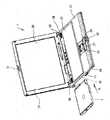
図1において、コンピューター1はヒンジ機構26、26を介して開閉するように構成されたノート型パソコンであり、一方が液晶ディスプレイ21が表面に形成されたディスプレイ側本体20であり、他方はキーボードセクション23が設けられたキーボード側本体22である。それぞれディスプレイ側本体20、キーボード側本体22共に略矩形状のハウジングを有し、ヒンジ機構26、26で折り曲げてディスプレイ側のラッチ機構31と、キーボード側のラッチ機構32をはめ込むことで、ノート型パソコンは完全に閉じられた状態とされて携帯に利用される。
【0015】
キーボードの詳細図示は省略するが、キーボードセクション23には、複数のキーが設けられている。キーボードの形式としては、種種のものがあり、JIS配列、QWERTY配列、101キーボード、109キーボード等があり、いずれでも良い。又、日本語キー(かなキー)、英字キー、数字キーの全て又はいずれかを含んでも良い。
【0016】
キーボードセクション23が設けられたキーボード側本体22には、該キーボードセクション23よりも手前側にパームレスト部が形成され、このパームレスト部の中央やや左寄りにタッチパッド部25が形成され、さらにそのタッチパッド部25の手前側に対をなす左ボタン27、右ボタン28が形成される。外付けマウスを接続しない場合などでは、これらタッチパッド部25、ボタン27、28を操作することによって当該コンピューターは制御可能とされる。また、キーボードセクション23とヒンジ機構26の間のキーボード側本体22の表面角部には、一対のスピーカー29、29が形成され、これらスピーカー29、29から所要の音を出すことができる。
【0017】
このような構造のノート型パソコンの向かって左側の側部30には、拡張ユニット2を挿入するための挿入口33がほぼキーボードセクション23に近い部分で設けられており、その挿入口33から拡張ユニット2を図中A方向に挿入することで、拡張ユニット2をコンピューター1に装着することができる。
【0018】
挿入口33で示され、拡張ユニット2が搭載されるノート型パソコンの搭載スペースは、拡張ベイ、マルチパーパスベイ、マルチベイ、多目的ベイ等と称されるものである。特に携帯型情報処理装置(携帯型パーソナルコンピュータ、ノート型コンピュータ又は携帯型電子機器、以下同様)では、前記ベイを設けて、種種の拡張ユニット(周辺機器等、例えば、FDD,HDD,CD−ROMドライブ)が挿入可能になっているものがある。このベイは、前記拡張ユニットをユーザが着脱可能に(着脱自在に)挿入できる構成を取り、又、複数の拡張ユニット(周辺機器等、例えば、FDD,HDD,CD−ROMドライブ)の1を選択して、前記ベイに挿入する構成をとる。即ち、ユーザは複数の拡張ユニットを事前に有しており、必要に応じて、前記複数の拡張ユニットをベイに挿入/取り外しして使用する。例えば、ユーザがFDDを使用したいときは、ベイにFDDを挿入して、フロッピーディスクを使用可能とする。その後、ユーザがCD−ROMを使用したいときは、前記ベイに挿入されているFDDを抜き取り、CD−ROMドライブをベイに挿入して、CD−ROMを使用可能にする。携帯型情報処理装置等のベイは、デスクトップ情報処理装置のベイやスロットと比べて、拡張ユニットがユーザが自由に着脱可能な点が大きく相違する。デスクトップ情報処理装置にもベイと称されるものがあるが、そこに周辺機器が挿入されるときは、ネジ止め等で着脱できないように周辺機器が取り付けられる。携帯型情報処理装置等のベイは、装置や機器の実装体積/面積が小さい故に設けられる。例えば、FDD,CD−ROMドライブの両者を携帯型情報処理装置に予め設けることは可能であるが、その構成をとると、両方の装置の実装領域が必要となり、携帯型情報処理装置は大きくなる。つまり、ユーザが求める周辺機器が多ければ多いほど、装置は大きくなる。しかりとすれば、携帯型情報処理装置の小型化は達成できない。そこで、上述した様に、1のベイに複数の拡張ユニットの中から選択し、ユーザが着脱可能の態様で、前記ベイに拡張ユニットが取り付けられる構成を取る。このような、ベイは、種種のノート型コンコンピュータ、携帯型情報処理装置、携帯型パーソナルコンピュータ又は携帯型電子機器で採用されている。又、前記ベイを複数有するこれらの装置もある。更に、取り付けられる拡張ユニットは、FDDやCD−ROMのみならず、DVDドライブやバッテリなども提供されている。又、前記ベイは種種の用語で称されることがあり、拡張ベイ、拡張ベイスロットやマルチパーパースベイ(多目的ベイ)と称されることもある。
【0019】
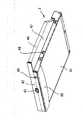
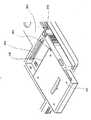
図2および図3は拡張ユニット2のそれぞれ斜視図であり、この拡張ユニット2はCD−ROM用のディスクドライブ装置である。まず、この拡張ユニット2の表面側には、前記コンピューター1の側部30と同じ側面を拡張ユニット2の装着時に形成する表面パネル42が設けられ、この表面パネル42の略中央には、ディスクの出し入れのための図示しないトレイを引き出す際に押すボタン43が設けられ、その斜め下のほうには、強制イジェクト用の穴49が設けられている。この強制イジェクト用の穴49は、電源が入っていないときに、中に入った媒体を取り出すためのもので、この穴49の中に、先のとがったもの(例えば、ボールペンなど)をさすことにより、トレイが飛び出すように設計されている。この拡張ユニット2は略矩形状の筐体を有するが、その上面41側は底面51よりも広くされ、特に、一方の側壁は略上側だけが突出した薄厚部44が形成されている。これはCD(コンパクトディスク)のサイズを考慮し、そのCDを載せるトレイの位置が上側とされ、逆にCDを載せない下側の筐体を小さく形成して、余分なスペースを占めないようにしたためである。図3に示すように、薄厚部44には、拡張ユニット2の上面41と底面51にそれぞれ平行な中間面47が下向きに形成されており、その中間面47の下の拡張ユニット2の側壁には当該拡張ユニットの抜け止めに用いられるロック溝48が設けられている。
【0020】
薄厚部44の裏面側は、円盤であるCD、CD−ROMの形状に起因して拡張ユニット2の移動方向に対して斜めに切りかかれており、更に、拡張ユニット2の周囲のスペースを余分に占有しないようになされている。拡張ユニット2の裏面部46には、コンピューター本体と電気的に接続するためのコネクタ45が設けられており、拡張ユニット2が挿入された時にはコンピューター内部のコネクタと接続される。このコネクタ45を介して拡張ユニット2は電気信号を送受信し所要の機能を発揮する。また、拡張ユニット2の底面51には、その表面パネル42側に拡張ユニット2の装着時にコンピューター1の底面と連続面を形成するエプロン部50が設けられている。
【0021】
次に、図4乃至図6を参照しながら、拡張ユニット2の取り外し機能とロック機能を備えたロック装置について説明する。このロック装置は、回動動作する回動片11と、該回動片11に噛合するピニオンギア12と、該ピニオンギアに噛合するラック部13を一端に形成し拡張ユニット2を押すための押圧部16を他端に設けたフレーム部材14と、そきフレーム部材14の位置に連動して出没自在とされる係合部15とを主たる構成要素としている。
【0022】
回動片11は回動軸104を挿通するための軸穴74を有し、その軸穴74を中心とした部分の周面にはギヤ部73が形成されている。ギヤ部73は軸穴74の軸方向と水平方向に溝が切られている。このギヤ部73は回動片11の最大回動角度に応じた角度とマージンだけ歯部分があれば良いことから、本実施形態では約90度の範囲だけ設けられている。このギヤ部73と軸穴74を挟んで対向する側には回動操作するためのアーム部75が形成されている。このアーム部75はギヤ部73を有した周面からその接線方向に延在する形で形成されており、アーム部75を後述する回動片収納部に収めた時にはアーム部75の外側面がコンピューター1の側面30と同じ面を形成する。この回動片11のアーム部75の先端には、使用者の指先や爪などで回動片11を引っかけて引き出すためにアーム部75の外側面をそのまま延長させた突設部71が設けられている。また、回動片11のアーム部75の裏面には、そのアーム部75に延在方向に沿って溝76が設けられおり、この溝76は軸穴74の周囲にも至るように形成されている。この溝76は図6に示すようにコイルバネ101を収納して係合させるための溝である。コイルバネ101の一端はアーム部75の溝76に係合する。前記回動軸104はコンピューター本体の前記拡張ユニット2の挿入口33の近傍に配設され、この回動軸104を中心に回動片11は回動操作されることになる。
【0023】
ピニオンギヤ12は軸103を中心として回転自在に支持されている。このピニオンギヤ12はその周囲に設けられたギヤ部81が前記回動片11のギヤ部73と噛合すると共に次に説明するラックギア部13にも噛合する。ギヤ部81は軸103の軸方向と水平方向に溝が切られている。ピニオンギヤ12と回動片11はそれぞれの軸が互いに平行とされ、且つ互いに噛合するため、回動片11が回動するとピニオンギヤ12は反対方向に回転し、例えば、回動片11をロック解除のために時計回りに回動させた場合、ピニオンギヤ12は反時計回りに回転する。このピニオンギヤ12の軸103には、回動片11の回動軸104に巻き付けられたコイルバネ101の他端が係合しており、回動片11がコイルバネ101の弾性力に抗じて回動操作された際、コイルバネ101はこの回動片11を元の位置に戻すように作用する。
【0024】
このピニオンギヤ12と噛合するラックギア部13は直線状の部材であり、ピニオンギヤ12のギア部81と噛合するように、垂直方向に溝が延在されて構成されたギヤ部84が設けられている。このラックギア部13の長手方向は拡張ユニット2の着脱時の移動方向である。ここで、回動片11とピニオンギヤ12とラックギア部13の位置関係は、略L字状に配列されたものとされ、ラックギア部13の長手方向の延長線上には、回動片11とピニオンギヤ12が存在せず、従って、ラックギア部13が移動してもこれら回動片11とピニオンギヤ12に接触することはない。また、ラックギア部13のギヤの範囲は回動片11の周面に形成されたギヤ部73を直線状に展開した長さと略等しい。ラックギア部13の一端部にはフレーム部材14に接続するブロック状の接続部85が設けられており、その接続部85の上面でフレーム部材14の上側板部材91から折り曲げられた一部が嵌合してラックギア部13とフレーム部材14は一体化される。
【0025】
フレーム部材14は金属或いは合成樹脂などで構成される帯状の部材であって、ラックギア部13と同様に、拡張ユニット2の着脱時の移動方向に平行に延在されている。そのコンピューターの側部に近い側の一端にはラックギア部13が一体に取り付けられており、コンピューターの内部側の端部には押圧部16が形成されている。この押圧部16は装着されている拡張ユニット2を取り外す際にその裏面46側から押すための部材である。押圧部16は帯状のフレーム部材14の端部を拡張ユニット2側に約直角に折り曲げて形成されており、その長さは拡張ユニット2のフレーム部材14側の裏面側角部を押すのに十分な長さである。これらラックギヤ部13から押圧部16までフレーム部材14と一体化されていることから、ラックギア部13が移動するように操作された場合には、フレーム部材14及び押圧部16が共に移動することになる。このフレーム部材14は、図6に示すように、支持板96の底面に沿って当接しながら移動可能に保持される。前記フレーム部材14と一体化されたラックギア部13も保持部材105に当接しながら移動可能に保持されており、これら保持部材105と支持板96の組み合わせから、フレーム部材14及びこれと一体化したラックギア部13は拡張ユニット2の移動方向と平行な方向にのみ移動できることになる。支持板96には上面からみて凹部とされた一対の取り付け穴97、97が設けられており、このように支持板96に凹部を以て取り付け穴97が設けられることで、螺子止めした場合でも支持板96の上面より螺子が突出することがなく、従って、後述するように拡張ユニット2の薄厚部44を密接して配置させることができ、コンピューター全体の小型化に大きく寄与する。
【0026】
前記フレーム部材14の上側板部材91の底面側には、拡張ユニット2の側面に形成されたロック溝48と拡張ユニット2の装着時に係合する係合部材15が配置されている。この係合部材15は平板状の回動する片であり、拡張ユニット2側に拡張ユニット2の側面に形成されたロック溝48と係合する係合突起93が設けられている。この係合突起93は係合部材15と同じ厚みをもって突設され、先端はロック溝48の形状と合わせてテーパー状とされている。この係合突起93の基端側では、係合部材15は略矩形状でその一部は係合突起93の反対側で係合部材15の外側に至る切欠部95を有している。従って、係合部材15を構成する材料にも依存するが、例えば合成樹脂によって形成した時では係合突起93をその合成樹脂が有する弾性を以て拡張ユニット2のロック溝48に係合させることができる。
【0027】
この係合部材15のラックギヤ部13に近い端部には、軸穴94が形成されており、この軸穴94に図示しない支軸を回動自在に通すことで、係合部材15は回動自在に支持されることになる。この係合部材15の軸穴94と係合する支軸はフレーム部材14ではなくコンピューター本体に固定される。これは次に説明するように、フレーム部材14の移動時に、このフレーム部材14の移動と連動して係合部材15の係合突起93をロック溝48から退かせるためである。係合突起93を拡張ユニット2のロック溝48から退かせる際には、係合部材15自体が軸穴94および図示しない支軸を中心に前記上側板部材91の裏面に沿って回動する。
【0028】
この係合部材15の回動は、係合部材15から垂直方向上側に突設され且つ拡張ユニット2の移動方向に対して斜めの面を有する斜面部17と、フレーム部材14の一部として設けられた斜面当接面18の連動によって制御される。係合部材15の斜面部17は、図4に示すように、係合部材15から垂直方向上側に突設された部分を拡張ユニット2に近い側がコンピューターの側面に近くなり、拡張ユニット2に遠い側がコンピューターの側面すなわち拡張ユニット2の挿入口33から遠くなるように切り欠いた部材であり、拡張ユニット2の移動方向には斜めであるが略垂直な面を有するように形成されている。この斜面部17と当接する斜面当接面18(図6)は上側板部材91から垂直に底面側に折り曲げられた側壁92の端部から該端部を延長するように設けられた面であり、図6に示すように拡張ユニット2に近い側から遠い側へ斜めに切り欠かれた部分の縁に沿って延在されている。これら斜面部17と斜面当接面18(図6)は略平行した面同士が当接しながらその当接位置を変えることができ、この当接した位置の移動によって、係合部材15の係合突起93の出没を制御できる。すなわち、拡張ユニット2がコンピューターに挿入され且つコンピューターに装着された時点では、斜面部17は斜面当接面18の側壁92に近い側に位置し、その部分で斜面当接面18は拡張ユニット2に対する距離が短いために、係合部材15の係合突起93をロック溝48(図4、図8)に対して挿入し、この係合突起93を保持することができる。また、ロックを解除する際には、回動片11の動作によって、フレーム部材14が拡張ユニット2の側壁に沿ってコンピューターの側面側に移動する。その結果、斜面部17は斜面当接面18の側壁92から遠い側に位置し、その部分で斜面当接面18は拡張ユニット2に対する距離が長いために、係合部材15自体が軸穴94および図示しない支軸を中心に回動し、係合部材15の係合突起93をロック溝48から退かせることができる。従って、本実施形態のロック装置では、フレーム部材14との連動でロック解除が可能である。
【0029】
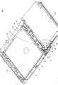
このようなフレーム部材14の移動によってロック解除と拡張ユニット2の押し出しを同時に行うことのできるロック装置は、その全体の大きさが比較的小型であり、拡張ユニット2の薄厚部44の下部に収納されるように配設されている。図8に示すように、拡張ユニット2はその側部には薄厚部44が形成されており、その薄厚部44の下部のスペースを有効に活用して、本実施形態の回動片11、ピニオンギヤ12、ラックギヤ部13、フレーム部材14、係合部材15および押圧部16が配設される。これら回動片11、ピニオンギヤ12、ラックギヤ部13、フレーム部材14、係合部材15および押圧部16のコンピューター本体の厚み方向の高さは、薄厚部44の下部に納まる高さであり、しかもこの高さの範囲の動作だけで、本実施形態は、ロック解除と拡張ユニット2の押し出しを同時に行うことができる。
【0030】
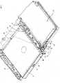
図7は拡張ユニット2を取り外したところのロック装置の斜視図である。拡張ユニット2の下部のエプロン部50と拡張ユニット2の装着時に面一となるように構成された底板111が拡張ユニット2の挿入部分に形成されており、この底板111の挿入口側にはエプロン部50の円弧状の端部に合わせた円弧状の端部が形成される。この拡張ユニット2の挿入部分はコンピューター本体の裏面パネル112の近くまで及ぶ。また、前記ロック装置の拡張ユニット2の反対側の側部には、電池ユニットなどを配置するための領域113がある。この領域113と拡張ユニット2の挿入部分の底板111の間の縦長の領域に、前述の回動片11、ピニオンギヤ12、ラックギヤ部13、フレーム部材14、係合部材15および押圧部16などより構成されるロック装置が配設される。特に、フレーム部材14を移動操作するための回動片11は、コンピューター側部に形成された回動片収納部120に収納されており、このように回動片11が回動片収納部120に収納されることで、回動片11を不作動とする際に回動片11のアーム部75がコンピューター側部と面一となり、その部分で外見上も美観を保つことができ、不要なアーム部75の損壊を防止できる。
【0031】
次に、図9乃至図11を参照しながら、本実施形態のロック装置の動作について説明する。なお、図9から図11においては、ロック装置の動作を良く説明する目的で拡張ユニット2の薄厚部44は破断して図示していない。
【0032】
図9は拡張ユニット2がコンピューター本体に装着された状態を示している。この状態では、回動片11が回動片収納部120に収納され、回動片11のアーム部75がコンピューター側部と面一となっている。回動片11の周面に形成されたギヤ部73はピニオンギヤ12と噛合し、このピニオンギア12はフレーム部材14のラックギア部13と噛合する。この拡張ユニット2の装着時では、ピニオンギヤ12のラックギヤ部13上の位置は、コンピューター側部側の端部である。
【0033】
拡張ユニット2のロック溝48には、拡張ユニット2の装着時に係合部材15の係合突起93が係合する。このようにロック溝48に係合突起93が挿入するため、拡張ユニット2自体は、その側面の面内方向である拡張ユニット2の移動方向以外にはコンピューター筐体内で動かないことから固定されることになる。この時、前述した係合部材15の斜面部17は斜面当接面18の側壁92に近い側に位置し、その部分で斜面当接面18は拡張ユニット2に対する距離が短く、従って、この斜面当接面18と当接する斜面部17も拡張ユニット2に近づいた位置を占める。このため斜面部17と一体である係合部材15の係合突起93はロック溝48に挿入され、拡張ユニット2をロックして保持することができる。
【0034】
次に、図10に示すように、使用者が指で回動片11のアーム部75の先端の突設部71をコンピューター側部の面から起こし、さらに回動片11を指で保持しながら、回動片11を当該回動片11の内部に設けられたコイルバネ101の弾性力に抗じながら回動軸104を中心に回動操作する。すると、回動片11の回動軸104回りのギヤ部73が上から見た場合に時計回りに回転し、このギヤ部73と噛合するピニオンギヤ12は反時計方向に回転する。回動片11では、アーム部75が回動軸104から外周方向に延在した構造を有しているため、アーム部75の先端を梃子の原理により容易に回動させることができる。従って、拡張ユニット2が重く、且つ拡張ユニット2の裏面のコネクタ45の結合状態が固い場合に特に有利である。ピニオンギヤ12が反時計方向に回転することで、フレーム部材14に一体に取り付けられたラックギア部13は水平方向に拡張ユニット2の挿入口33側に直線的に移動させられ、従って、フレーム部材14全体もピニオンギヤ12の回転に伴ってコンピューター側部に向かって移動させられる。
【0035】
このフレーム部材14の移動に伴って斜面部17と斜面当接面18の位置関係が、側壁92から遠い側すわなち斜めの切欠が深い部分で斜面部17と斜面当接面18が当接するようになり、その部分で斜面当接面18は拡張ユニット2に対する距離が長く、係合部材15は斜面当接面18に規制されずに図示しない支軸を中心に回動可能な状態に移行する。これと同時に、フレーム部材14の裏面側の端部に形成された押圧部16が、拡張ユニット2の裏面46の角部を拡張ユニット2を外部に押し出す方向に押す。すると、拡張ユニット2は裏面46に配されたコネクタ45がまずコンピューター本体側のコネクタから外れて電気的に遮断された状態になり、さらに押圧部16の押圧動作によって、コンピューター側部の方向に移動する。
【0036】
このときロック溝48の内部の係合突起93は、ロック溝48の内壁に当接後、該係合突起93を有する係合部材15は既に回動可能となっているために、拡張ユニット2から離れる方向に退き、拡張ユニット2のロックが解除される。
【0037】
図11はロックが解除されて、拡張ユニット2が挿入口33より突出したところを示している。本実施形態では、回動片11の回動動作だけで、押圧部16の押圧から拡張ユニット2が側面方向に移動操作され、同時に係合突起93がロック溝48から外れるために、容易に且つ確実に拡張ユニット2を取り外すことが出来る。
【0038】
拡張ユニット2が取り外され、使用者が回動片11を操作するのを辞めた後では、回動片11はそのアーム部75の裏面に設けられた溝76内に係合してなるコイルバネ101の弾性力から元の位置、すなわち、回動片収納部120に収納され、アーム部75の面がコンピューター側部の面と面一となる位置に戻される。このようにバネの弾性力から自動で回動片11が戻るため、回動片11をいちいち戻すような指先の操作は不要であり、使用者は拡張ユニット2の取り扱いに専念することができ、コンピューターをさらに使い易いものとしている。
【0039】
なお、上述の実施形態では、回動片11を元の位置に戻すバネをコイルバネによるものとしたが、他のバネ、例えば板バネや合成樹脂の樹脂自体の弾性によって、元に戻すような機構を採用することも可能である。また、斜面当接面18と当接する斜面部17は必ずしも面形状を有するものでなくとも良く、斜めに切りかかれた斜面当接面18と当接しながら移動するものであれば、円筒状や球状、角棒状などの形状であっても良い。また、係合突起93をロック溝48から出没させる機構にバネなどを用いることも可能である。
尚、本実施形態は、以下の発明1乃至12も開示しているものであり、前記1乃至図12で説明されている。又、前述した効果も以下の発明1乃至12も奏するものである。
【0040】
発明1として、本実施形態は、「コンピューター本体に着脱自在とされ該コンピューター本体との接続時に所定の拡張機能を実現するための拡張ユニットを装着した時に該拡張ユニットを固定するためのロック装置において、前記ロック装置は、前記コンピューター本体の拡張ユニット挿入口近傍に配されギヤを有する周面が設けられた回動中心側を中心に回動操作される回動片と、前記ギヤと噛合するピニオンギヤと、前記拡張ユニットの着脱時の移動方向に沿って延在され前記ピニオンギヤと噛合するラックギヤ部が配設されると共に前記拡張ユニットの裏面部を該拡張ユニットを開放する際に押圧する押圧部が配設されたフレーム部材と、該コンピューター本体に回動可能に取り付けられ拡張ユニットの凹部に係合し前記フレーム部材の移動時に該凹部との係合が解除される係合部材とを有することを特徴とするコンピューター用拡張ユニットのロック装置。」をも更に開示している。
【0041】
発明2として、本実施形態は、「前記係合部材は前記ラックギアの延在方向に対して斜めに配設された斜面部を有し、該斜面部と平行な面を有する斜面当接面が前記フレーム部材に形成され、前記フレーム部材の移動に応じて前記斜面部と前記斜面当接部が当接して前記拡張ユニットの凹部への係合が解除されることを特徴とする発明1記載のコンピューター用拡張ユニットのロック装置。」をも更に開示している。
【0042】
発明3として、本実施形態は、「前記フレーム部材の押圧部は該フレーム部材を前記拡張ユニットの裏面部側で該裏面部に沿って該フレーム部材の一部を折り曲げて形成されたものであることを特徴とする発明1記載のコンピューター用拡張ユニットのロック装置。」をも更に開示している。
【0043】
発明4として、本実施形態は、「前記回動片は該回動片を操作しない際に前記コンピューター本体の側部に設けられた回動片収納部に収納されることを特徴とする発明1記載のコンピューター用拡張ユニットのロック装置。」をも更に開示している。
【0044】
発明5として、本実施形態は、「前記回動片の先端部には爪または指先で操作するための突設部が設けられていることを特徴とする発明1記載のコンピューター用拡張ユニットのロック装置。」をも更に開示している。
【0045】
発明6として、本実施形態は、「前記回動片にはバネ部材が係合し、前記回動片を該バネ部材の弾性力に反して回動させて、当該ロック装置のロックを解除すると共に、前記回動片を放すことで前記バネ部材の弾性力から前記回動片は前記回動片収納部に収納されることを特徴とする発明4記載のコンピューター用拡張ユニットのロック装置。」をも更に開示している。
【0046】
発明7として、本実施形態は、「前記拡張ユニットは一方の側部が薄い厚みの薄厚部を有し、その薄厚部の垂直方向に重なるように前記回動片、前記ピニオンギア、前記フレーム部材、及び前記係合部材が配設されることを特徴とする発明1記載のコンピューター用拡張ユニットのロック装置。」をも更に開示している。
【0047】
発明8として、本実施形態は、「前記コンピューター本体の側部に設けられた前記回動片を収納する回動片収納部は前記拡張ユニットの前記薄厚部の垂直方向で重なって位置することを特徴とする発明7記載のコンピューター用拡張ユニットのロック装置。」をも更に開示している。
【0048】
発明9として、本実施形態は、「前記コンピューター本体は携帯型情報端末であることを特徴とする発明1記載のコンピューター用拡張ユニットのロック装置。」をも更に開示している。
【0049】
発明10として、本実施形態は、「コンピューター本体に着脱自在とされ該コンピューター本体との接続時に所定の拡張機能を実現するための拡張ユニットを装着した後、該拡張ユニットを取り外す方法において、回動片を回動操作することで前記拡張ユニットの移動方向に沿って延在されたフレーム部材を該移動方向に移動させ、前記フレーム部材に配設された押圧部が前記拡張ユニットの裏面を押圧すると共に前記フレーム部材に設けられた係合部材が前記拡張ユニットの凹部から外れ、前記拡張ユニットがコンピューター本体から取り外し可能となることを特徴とするコンピューター用拡張ユニットの取り外し方法。」をも更に開示している。
【0050】
発明11として、本実施形態は、「前記回動片の回動動作がピニオンギアとラックギアの組み合わせによって直線動作に変換されてフレーム部材を移動させることを特徴とする発明10記載のコンピューター用拡張ユニットの取り外し方法。」をも更に開示している。
【0051】
発明12として、本実施形態は、「前記係合部材は前記拡張ユニットの移動方向に対して斜めに配設された斜面部を有し、該斜面部と平行な面を有する斜面当接面が前記フレーム部材に形成され、前記フレーム部材の移動に応じて前記斜面部と前記斜面当接部が当接して前記拡張ユニットの前記凹部への係合が解除されることを特徴とする発明10記載のコンピューター用拡張ユニットの取り外し方法。」をも更に開示している。
【0052】
【発明の効果】
本発明のロック装置によれば、回動片の回動動作だけで、押圧部の押圧から拡張ユニットが側面方向に移動操作され、同時に係合突起がロック溝から退いて外れるために、容易に且つ確実に拡張ユニットを取り外すことが出来る。このロック装置は、拡張ユニットの薄厚部の下部にも収納できる小型な機構部であり、従って、コンピューター本体内のスペースを極めて有効に使用することができる。
【図面の簡単な説明】
【図1】本発明のロック装置の実施形態が適用されるノート型コンピューターと該コンピューターに取り付けられる拡張ユニットの一例の斜視図である。
【図2】前記拡張ユニットの上側から見た斜視図である。
【図3】前記拡張ユニットの底面側から見た斜視図である。
【図4】本発明の前記ロック装置の実施形態の上側からの要部斜視図である。
【図5】本発明の前記ロック装置の実施形態の底側からの要部斜視図である。
【図6】係合部材を除いた本発明の前記ロック装置の実施形態を底側から見た要部斜視図である。
【図7】本発明の前記ロック装置の実施形態のコンピューター内部における配置を示す斜視図である。
【図8】本発明の前記ロック装置の実施形態の拡張ユニットとの位置関係を示す斜視図である。
【図9】本発明の前記ロック装置の実施形態の動作を示す斜視図であって、拡張ユニットの装着時の状態を示す図である。
【図10】本発明の前記ロック装置の実施形態の動作を示す斜視図であって、拡張ユニットのロックが解除された状態を示す図である。
【図11】本発明の前記ロック装置の実施形態の動作を示す斜視図であって、拡張ユニットが押し出された状態を示す図である。
【図12】従来の拡張ユニットの取り付け構造を示す斜視図である。
【符号の説明】
1 コンピューター
2 拡張ユニット
11 回動片
12 ピニオンギヤ
13 ラックギア部
14 フレーム部材
15 係合部材
16 押圧部材
17 斜面部
18 斜面当接部
20 ディスプレイ側本体
21 液晶ディスプレイ
22 キーボード側本体
23 キーボードセクション
25 タッチパネル部
26 ヒンジ機構
27 左ボタン
28 右ボタン
29 スピーカ
31 ラッチ機構
32 ラッチ機構
33 挿入口
41 上面
42 表面パネル
43 ボタン
44 薄厚部
45 コネクタ
46 裏面
50 エプロン部
51 底面
71 突設部
73 ギヤ部
74 軸穴
75 アーム部
81 ギヤ部
82 軸穴
91 上側板部材
93 係合突起
94 軸穴
101 コイルバネ
120 回動片収納部[0001]
BACKGROUND OF THE INVENTION
The present invention provides a lock for fixing an extension unit to a computer main body and releasing the fixed state when an extension unit for realizing a required function is attached to a computer such as a notebook personal computer. It relates to the device.
[0002]
[Prior art]
While portable electronic information terminals represented by so-called notebook personal computers are increasingly demanded for higher functionality, further reductions in size and weight are required. Such notebook computers are designed to be equipped with a system that realizes the functions in a portable size such as A4 size or B5 size, and an expansion unit for changing and expanding the functions as necessary. Is detachably attached. Such expansion units include, for example, CD-ROM disk devices, 3.5-inch floppy disk device, power supply, imaging device camera unit, PC card slot, printer, scanner, network device, etc. Depending on the situation, it has various configurations.
[0003]
These various types of expansion units usually have a casing with a common size, and each expansion unit corresponding to a required function is configured to be inserted and attached from the side or bottom of the keyboard side casing of the computer body. The If a different function is required, it can be realized by a computer by replacing the unit with another expansion unit. When the expansion unit is attached to the casing of the computer main body, it is often structured to form a part of the casing, and once attached, the locking mechanism provided in the casing is easily attached to the expansion unit. Many lock the expansion unit to prevent it from falling off.
[0004]
FIG. 12 shows an example of an expansion unit locking device in a conventional computer. As shown in FIG. 12, the
[0005]
In this lock device, when the
[0006]
[Problems to be solved by the invention]
In such a conventional locking device for an expansion unit in a computer, first, when removing the
[0007]
However, if the computer is connected to a cable such as a printer or a telephone line to the modem, or if the user is a child or a disabled person, the computer itself may be turned over or tilted. If it is not easy, for example if it cannot be turned upside down, the bottom of the computer is lifted and the
[0008]
In view of the above technical problems, an object of the present invention is to provide a lock device that can easily attach and detach an expansion unit to a computer body such as a notebook personal computer.
[0009]
[Means for Solving the Problems]
The lock device for an expansion unit for a computer according to the present invention is a lock for fixing the expansion unit when the expansion unit is attached to the computer main body and is mounted so as to realize a predetermined expansion function when connected to the computer main body. In the apparatus, a rotation piece disposed near the expansion unit insertion opening of the computer main body and rotated, and extending along a moving direction when the expansion unit is attached / detached. A first member provided with a pressing portion that moves in the extending direction by a moving operation and presses the expansion unit when the expansion unit is opened, and a second member to engage with the engagement portion of the expansion unit. And a second member that is disengaged from the engaging portion when the first member is moved.
[0010]
According to the said structure, a 1st member moves to the extension direction by rotation operation | movement of a rotation piece. Along with the movement of the first member, when the extension unit is opened, the pressing part that presses the extension unit pushes the extension unit in the direction of removing the extension unit from the back side. Since the engagement of the second member with the engaging portion of the extension unit is released as the first member moves, the extension unit is unlocked and removed simultaneously from the turning operation of one turning piece. . Therefore, the extension unit can be easily replaced by using the locking device of the present invention.
[0011]
Further, the present invention provides a method for removing a rotation piece after attaching an expansion unit that is detachable to a computer main body and realizes a predetermined expansion function when connected to the computer main body. By operating, the first member extended along the moving direction of the expansion unit is moved in the moving direction, and the pressing portion disposed on the first member presses the expansion unit and the first member The engaging member provided on the member is disengaged from the engaging portion of the extension unit, and the extension unit is removable from the computer main body.
[0012]
Also according to the above method, since the engagement with the engaging portion of the engaging member is released along with the movement of the first member simultaneously with the pressing operation of the back surface of the expansion unit, the unlocking and taking out of the expansion unit are performed in one way. It is performed simultaneously from the turning operation of the turning piece. Therefore, the extension unit can be easily replaced by using the locking device of the present invention.
[0013]
DETAILED DESCRIPTION OF THE INVENTION
A preferred embodiment of the locking device of the present invention will be described with reference to the drawings. The present embodiment is an example of a lock device mounted on a notebook computer. First, a notebook computer and an expansion unit will be described with reference to FIGS. 1 to 3.
[0014]
In FIG. 1, a computer 1 is a notebook personal computer configured to open and close via
[0015]
Although the detailed illustration of the keyboard is omitted, the
[0016]
The keyboard-side
[0017]
An
[0018]
The mounting space of the notebook type personal computer, which is indicated by the
[0019]
2 and 3 are perspective views of the
[0020]
The back surface side of the
[0021]
Next, with reference to FIGS. 4 to 6, a lock device having a function of removing the
[0022]
The rotating
[0023]
The
[0024]
The
[0025]
The
[0026]
On the bottom surface side of the
[0027]
A
[0028]
The rotation of the
[0029]
Such a locking device that can simultaneously perform unlocking and pushing out the
[0030]
FIG. 7 is a perspective view of the locking device with the
[0031]
Next, the operation of the locking device according to the present embodiment will be described with reference to FIGS. 9 to 11, the
[0032]
FIG. 9 shows a state in which the
[0033]
When the
[0034]
Next, as shown in FIG. 10, the user raises the protruding
[0035]
As the
[0036]
At this time, since the
[0037]
FIG. 11 shows the
[0038]
After the
[0039]
In the above-described embodiment, the spring for returning the
The present embodiment also discloses the following inventions 1 to 12, and has been described with reference to FIGS. In addition, the above-described effects are also exhibited by the following inventions 1 to 12.
[0040]
As a first aspect of the present invention, the present embodiment provides a lock device for fixing an expansion unit when the expansion unit is attached to the computer main body and is attached to the computer main body to realize a predetermined expansion function. The locking device includes a rotation piece that is rotated around a rotation center side provided with a peripheral surface having a gear disposed in the vicinity of the expansion unit insertion opening of the computer main body, and a pinion gear that meshes with the gear. And a rack gear portion that extends along a moving direction when the extension unit is attached and detached and meshes with the pinion gear, and a pressing portion that presses the back surface portion of the extension unit when opening the extension unit. A frame member disposed on the computer main body and pivotally attached to the recess of the expansion unit; Locking device for computer expansion unit and having an engaging member which engages with the concave portion is released during the movement. "Further discloses also.
[0041]
As the
[0042]
As an invention 3, the present embodiment states that “the pressing portion of the frame member is formed by bending a part of the frame member along the back surface portion of the frame member on the back surface side of the extension unit. Further disclosed is a locking device for an expansion unit for a computer according to the first aspect of the invention.
[0043]
According to a fourth aspect of the present invention, “the rotating piece is stored in a rotating piece storage portion provided on a side portion of the computer main body when the rotating piece is not operated. Further disclosed is a locking device for a computer expansion unit.
[0044]
According to a fifth aspect of the present invention, there is provided a computer extension unit lock according to the first aspect of the present invention, wherein a protruding portion for operation with a nail or a fingertip is provided at a tip of the rotating piece. The apparatus is further disclosed.
[0045]
As a sixth aspect of the present invention, a spring member is engaged with the rotating piece, and the rotating piece is rotated against the elastic force of the spring member to release the lock of the locking device. In addition, the locking piece of the expansion unit for a computer according to
[0046]
As an invention 7, the present embodiment states that "the extension unit has a thin part with a thin thickness on one side, and the rotating piece, the pinion gear, and the frame member so as to overlap each other in the vertical direction of the thin part. And a locking device for a computer expansion unit according to the first aspect, wherein the engagement member is disposed.
[0047]
As an eighth aspect of the present invention, the present embodiment states that “the rotating piece storage portion for storing the rotating piece provided on the side portion of the computer body is positioned so as to overlap in the vertical direction of the thin portion of the extension unit. Further disclosed is a locking device for an expansion unit for a computer according to a seventh aspect of the invention.
[0048]
As an invention 9, this embodiment further discloses "the computer expansion unit locking device according to the invention 1, wherein the computer main body is a portable information terminal".
[0049]
As a tenth aspect of the present invention, in the method of removing the expansion unit after attaching the expansion unit that is detachable to the computer main body and realizes a predetermined expansion function when connected to the computer main body, The frame member extended along the moving direction of the extension unit is moved in the moving direction by rotating the piece, and the pressing portion disposed on the frame member presses the back surface of the extension unit. In addition, there is further disclosed a method for removing a computer extension unit, wherein an engagement member provided on the frame member is disengaged from the recess of the extension unit, and the extension unit is removable from the computer main body. ing.
[0050]
According to an eleventh aspect of the present invention, there is provided an expansion unit for a computer according to the tenth aspect of the present invention, wherein the rotational movement of the rotational piece is converted into a linear movement by a combination of a pinion gear and a rack gear to move the frame member. Is also disclosed.
[0051]
As a twelfth aspect of the present invention, “the engagement member has a slope portion disposed obliquely with respect to the moving direction of the extension unit, and a slope contact surface having a plane parallel to the slope portion is provided. 11. The invention according to claim 10, wherein the slope member and the slope contact portion are formed on the frame member, and the engagement of the expansion unit with the concave portion is released according to the movement of the frame member. The method of removing the computer expansion unit is also disclosed.
[0052]
【The invention's effect】
According to the locking device of the present invention, the expansion unit is moved and operated in the lateral direction from the pressing of the pressing portion only by the rotating operation of the rotating piece, and at the same time, the engaging protrusion is retracted from the locking groove and is easily removed. And the expansion unit can be removed reliably. This locking device is a small mechanism part that can be stored in the lower part of the thin part of the expansion unit, and therefore, the space in the computer main body can be used very effectively.
[Brief description of the drawings]
FIG. 1 is a perspective view of an example of a notebook computer to which an embodiment of a locking device of the present invention is applied and an expansion unit attached to the computer.
FIG. 2 is a perspective view of the extension unit as seen from above.
FIG. 3 is a perspective view of the extension unit as seen from the bottom side.
FIG. 4 is a perspective view of a main part from the upper side of the embodiment of the locking device of the present invention.
FIG. 5 is a perspective view of a main part from the bottom side of the embodiment of the locking device of the present invention.
FIG. 6 is a perspective view of an essential part of the embodiment of the locking device according to the present invention, excluding the engaging member, as viewed from the bottom side.
FIG. 7 is a perspective view showing an arrangement in the computer of the embodiment of the locking device of the present invention.
FIG. 8 is a perspective view showing a positional relationship with the expansion unit of the embodiment of the locking device of the present invention.
FIG. 9 is a perspective view showing the operation of the embodiment of the locking device of the present invention, and shows a state when the extension unit is mounted.
FIG. 10 is a perspective view showing the operation of the embodiment of the lock device of the present invention, and shows a state in which the lock of the expansion unit is released.
FIG. 11 is a perspective view showing an operation of the embodiment of the locking device of the present invention, and showing a state in which an extension unit is pushed out.
FIG. 12 is a perspective view showing a conventional extension unit mounting structure.
[Explanation of symbols]
1 computer
2 Expansion unit
11 Rotating piece
12 Pinion gear
13 Rack gear section
14 Frame member
15 Engagement member
16 Pressing member
17 Slope
18 Slope contact part
20 Display side body
21 Liquid crystal display
22 Keyboard side body
23 Keyboard section
25 Touch panel
26 Hinge mechanism
27 Left button
28 Right button
29 Speaker
31 Latch mechanism
32 Latch mechanism
33 insertion slot
41 Upper surface
42 Front panel
43 buttons
44 Thin section
45 connector
46 Back
50 Apron Club
51 Bottom
71 Projection
73 Gear part
74 Shaft hole
75 Arm
81 Gear part
82 Shaft hole
91 Upper plate member
93 Engagement protrusion
94 Shaft hole
101 Coil spring
120 Rotating piece storage
Claims (10)
Translated fromJapanese前記コンピューター本体の拡張ユニット挿入口近傍に配され、回動操作されるための回動片と、
前記拡張ユニットの着脱時の移動方向に沿って延在され、前記回動片の回動操作によって前記延在方向に移動し、該拡張ユニットを開放する際に前記拡張ユニットを押圧する押圧部が配設された第1部材と、
拡張ユニットの係合部に係合するための第2部材であって、前記第1部材の移動時に該係合部との係合が解除される第2部材とを有し、
前記第2部材は前記延在方向に対して斜めに配設された斜面部を有し、該斜面部と平行な面を有する斜面当接面が前記第1部材に形成され、前記第1部材の移動に応じて前記斜面部と前記斜面当接部が当接して前記拡張ユニットの係合部への係合が解除されることを特徴とするコンピューター用拡張ユニットのためのロック装置。In a locking device for fixing the expansion unit when the expansion unit is attached to the computer main body and attached to the computer main body to realize a predetermined expansion function when connected to the computer main body.
A rotating piece arranged in the vicinity of the expansion unit insertion port of the computer main body, and to be rotated;
A pressing portion that extends along a moving direction when the extension unit is attached and detached, moves in the extending direction by a turning operation of the turning piece, and presses the extension unit when the extension unit is opened. A disposed first member;
A second member for engaging with the engaging portion of the expansion unit, the second member being disengaged from the engaging portion when the first member is moved,
The second member has a slope portion disposed obliquely with respect to the extending direction, and a slope contact surface having a plane parallel to the slope portion is formed on the first member. A locking device for a computer extension unit, wherein the slope part and the slope contact part come into contact with each other in accordance with movement of the extension unit and the engagement of the extension unit with the engaging part is released.
回動片を回動操作することで前記拡張ユニットの移動方向に沿って延在された第一部材を該移動方向に移動させ、前記第一部材に配設された押圧部が前記拡張ユニットを押圧すると共に前記第一部材に設けられた係合部材が前記拡張ユニットの係合部から外れ、前記拡張ユニットがコンピューター本体から取り外し可能となり、
前記係合部材は前記拡張ユニットの移動方向に対して斜めに配設された斜面部を有し、該斜面部と平行な面を有する斜面当接面が前記第一部材に形成され、前記第一部材部材の移動に応じて前記斜面部と前記斜面当接部が当接して前記拡張ユニットの前記係合部への係合が解除されることを特徴とするコンピューター用拡張ユニットの取り外し方法。In a method of detaching the expansion unit after attaching the expansion unit to be detachable from the computer main body and realizing a predetermined expansion function when connected to the computer main body,
The first member extended along the moving direction of the extension unit is moved in the moving direction by rotating the rotating piece, and the pressing portion disposed on the first member causes the extension unit to move. The engaging member provided on the first member is released from the engaging portion of the expansion unit while being pressed, and the expansion unit is removable from the computer main body,
The engaging member has a slope portion disposed obliquely with respect to the moving direction of the extension unit, and a slope contact surface having a plane parallel to the slope portion is formed on the first member, A method of removing an expansion unit for a computer, wherein the slope portion and the slope contact portion come into contact with each other in accordance with the movement of one member member, and the engagement of the extension unit with the engagement portion is released.
前記ロック機構は、前記拡張ユニットの挿入口近傍に配され、回動操作されるための回動片と、
前記拡張ユニットの着脱時の移動方向に沿って延在され、前記回動片の回動操作によって前記延在方向に移動し、該拡張ユニットを開放する際に前記拡張ユニットを押圧する押圧部が配設された第1部材と、
拡張ユニットの係合部に係合するための第2部材であって、前記延在方向に対して斜めに配設された傾斜部を有し、該斜面部と平行な面を有する斜面部当接面が前記第1部材に形成され、前記第1部材の移動に応じて前記斜面部と前記斜面当接部が当接して前記拡張ユニットの係合部への係合が解除される第2部材とを有することを特徴とするコンピューター。In a computer comprising a lock mechanism for detachably mounting an expansion unit for realizing a predetermined expansion function and fixing the mounted expansion unit,
The locking mechanism is arranged near the insertion port of the extension unit, and a rotating piece for rotating operation,
A pressing portion that extends along a moving direction when the extension unit is attached and detached, moves in the extending direction by a turning operation of the turning piece, and presses the extension unit when the extension unit is opened. A disposed first member;
A second member for engaging with the engaging portion of the expansion unit, having an inclined portion disposed obliquely with respect to the extending direction, and having an inclined surface portion having a surface parallel to the inclined surface portion. A contact surface is formed on the first member, and the slope portion and the slope contact portion come into contact with each other as the first member moves, and the engagement of the extension unit with the engagement portion is released. And a computer.
Priority Applications (3)
| Application Number | Priority Date | Filing Date | Title |
|---|---|---|---|
| JP24498799AJP3665235B2 (en) | 1999-08-31 | 1999-08-31 | Locking device for computer expansion unit |
| US09/513,141US6332658B1 (en) | 1999-08-31 | 2000-02-25 | Lock device for expansion unit in computer |
| DE10009973ADE10009973B4 (en) | 1999-08-31 | 2000-03-02 | Locking device for expansion unit in the computer |
Applications Claiming Priority (1)
| Application Number | Priority Date | Filing Date | Title |
|---|---|---|---|
| JP24498799AJP3665235B2 (en) | 1999-08-31 | 1999-08-31 | Locking device for computer expansion unit |
Publications (2)
| Publication Number | Publication Date |
|---|---|
| JP2001067146A JP2001067146A (en) | 2001-03-16 |
| JP3665235B2true JP3665235B2 (en) | 2005-06-29 |
Family
ID=17126906
Family Applications (1)
| Application Number | Title | Priority Date | Filing Date |
|---|---|---|---|
| JP24498799AExpired - Fee RelatedJP3665235B2 (en) | 1999-08-31 | 1999-08-31 | Locking device for computer expansion unit |
Country Status (3)
| Country | Link |
|---|---|
| US (1) | US6332658B1 (en) |
| JP (1) | JP3665235B2 (en) |
| DE (1) | DE10009973B4 (en) |
Families Citing this family (24)
| Publication number | Priority date | Publication date | Assignee | Title |
|---|---|---|---|---|
| DE10124635A1 (en)* | 2001-05-18 | 2002-11-21 | Scm Microsystems Gmbh | Blocking device for use with a set-top-box or similar to ensure that only one of the two available PCMCIA format slots can be used with an electronic card module when this a requirement of a particular card |
| US6606241B2 (en)* | 2001-06-29 | 2003-08-12 | Hewlett-Packard Development Company, L.P. | Ejection bay structure for portable computers |
| JP3832286B2 (en)* | 2001-08-03 | 2006-10-11 | 日本電気株式会社 | Electronics |
| US6978903B2 (en)* | 2002-04-04 | 2005-12-27 | Lg Electronics Inc. | Apparatus for receiving module for use in computer |
| KR100745248B1 (en)* | 2002-04-04 | 2007-08-01 | 엘지전자 주식회사 | Module storage unit for computer |
| DE20210362U1 (en) | 2002-07-04 | 2002-09-05 | STOCKO Contact GmbH & Co. KG, 42327 Wuppertal | PC card chip card reader |
| JP2004234194A (en)* | 2003-01-29 | 2004-08-19 | Toshiba Corp | Electronics |
| US20050039201A1 (en)* | 2003-08-12 | 2005-02-17 | First International Computer, Inc. | CD-ROM drive capable of rapidly installing and detaching |
| US7742292B1 (en) | 2004-03-12 | 2010-06-22 | Sun Microsystems, Inc. | Component array bracket assembly |
| US7283371B1 (en) | 2004-03-12 | 2007-10-16 | Sun Microsystems, Inc. | Device carrier system |
| US8434832B2 (en) | 2005-03-10 | 2013-05-07 | Hewlett-Packard Development Company, L.P. | Method and apparatus for locking a computer device |
| CN100530033C (en)* | 2006-05-26 | 2009-08-19 | 鸿富锦精密工业(深圳)有限公司 | Replacing apparatus |
| TW200822084A (en)* | 2006-11-15 | 2008-05-16 | Delta Electronics Inc | Extracting apparatus for removable hard disk drive |
| WO2009086704A1 (en)* | 2008-01-10 | 2009-07-16 | Clevo Co. | Lock device of notebook computer |
| JP4885176B2 (en)* | 2008-08-05 | 2012-02-29 | 日本航空電子工業株式会社 | Eject mechanism and electronic equipment |
| JP2010123197A (en)* | 2008-11-20 | 2010-06-03 | Fujitsu Ltd | Medium drive unit and electronic equipment |
| CN102455740B (en)* | 2010-10-20 | 2013-07-10 | 宏碁股份有限公司 | Battery module and notebook computer |
| CN102541166B (en) | 2010-12-15 | 2014-01-15 | 神基科技股份有限公司 | limit mechanism |
| US8801050B2 (en)* | 2011-03-09 | 2014-08-12 | King Slide Works Co., Ltd. | Locking device for case of portable electronic device |
| EP2608112B1 (en)* | 2011-12-21 | 2015-09-09 | Nokia Technologies Oy | An apparatus for a card holder |
| JP2014029747A (en)* | 2012-07-31 | 2014-02-13 | Fujitsu Ltd | Mounting unit attaching device and electronic apparatus including the same |
| JP6041598B2 (en)* | 2012-09-21 | 2016-12-14 | 富士通株式会社 | Electronic device, case unit, and lock device |
| US10315439B2 (en)* | 2017-07-15 | 2019-06-11 | Hewlett-Packard Development Company, L.P. | Transmissions with retention noses |
| US20250138604A1 (en)* | 2023-10-27 | 2025-05-01 | Hewlett Packard Enterprise Development Lp | Hot swappable drive cage |
Family Cites Families (8)
| Publication number | Priority date | Publication date | Assignee | Title |
|---|---|---|---|---|
| US4914552A (en)* | 1989-06-26 | 1990-04-03 | Rexnord Holdings Inc. | Printed circuit board installation and retaining apparatus |
| US5222897A (en)* | 1992-04-01 | 1993-06-29 | Emc Corporation | Circuit board inserter/ejector system |
| JPH0981269A (en) | 1995-09-14 | 1997-03-28 | Canon Inc | Electronic device with communication function and control method thereof |
| US5721669A (en)* | 1995-09-15 | 1998-02-24 | Apple Computer, Inc. | Gear-driven docking apparatus for removable mass-storage drives |
| JPH09231735A (en) | 1996-02-22 | 1997-09-05 | Nec Home Electron Ltd | Portable information processor |
| US5730610A (en)* | 1996-03-22 | 1998-03-24 | Berg Technology, Inc. | Memory card connector having a spring restrained activator rod and folding push button mechanism |
| US5805420A (en)* | 1996-04-09 | 1998-09-08 | Scitex Digital Video, Inc. | Mounting assembly for removable installation of electronic components into a housing |
| JP2872100B2 (en) | 1996-04-12 | 1999-03-17 | 静岡日本電気株式会社 | Docking station and laptop retention mechanism |
- 1999
- 1999-08-31JPJP24498799Apatent/JP3665235B2/ennot_activeExpired - Fee Related
- 2000
- 2000-02-25USUS09/513,141patent/US6332658B1/ennot_activeExpired - Fee Related
- 2000-03-02DEDE10009973Apatent/DE10009973B4/ennot_activeExpired - Fee Related
Also Published As
| Publication number | Publication date |
|---|---|
| DE10009973B4 (en) | 2005-02-03 |
| DE10009973A1 (en) | 2001-03-15 |
| JP2001067146A (en) | 2001-03-16 |
| US6332658B1 (en) | 2001-12-25 |
Similar Documents
| Publication | Publication Date | Title |
|---|---|---|
| JP3665235B2 (en) | Locking device for computer expansion unit | |
| KR100924038B1 (en) | Keyboard removal device for portable hybrid computer | |
| JP4320091B2 (en) | Expansion unit and portable information processing apparatus | |
| US5264986A (en) | Electronic apparatus equipped with detachable unit having retaining members, interlock, and locking cover plate | |
| US7859833B2 (en) | Function expansion device and electronic device system | |
| JP4667725B2 (en) | Portable information processing device | |
| KR100272780B1 (en) | Personal computer card slot | |
| US7428145B2 (en) | Electronic apparatus | |
| JP2005070969A (en) | Electronic device and operation unit used for electronic device | |
| US7699364B2 (en) | Housing of foldable device | |
| US20070047197A1 (en) | Electronic apparatus | |
| US7433181B2 (en) | Computer with data drive under keyboard | |
| WO2022111656A1 (en) | Detachable electronic device | |
| KR930009800B1 (en) | Portable electronic apparatus | |
| US7233314B2 (en) | Notebook having combined touch pad and CD-ROM drive | |
| US20070047191A1 (en) | Electronic apparatus | |
| US6574097B2 (en) | Battery module for notebook computers | |
| JP5078804B2 (en) | Information processing device | |
| US7283356B2 (en) | Electronic apparatus | |
| JP3100165U (en) | Computer | |
| JP3832286B2 (en) | Electronics | |
| CN102033574A (en) | Notebook computer with pivotable battery holder | |
| CN101661771B (en) | Electronic device and optical storage device thereof | |
| CN222107991U (en) | Protective case for electronic device | |
| US20050162825A1 (en) | Information processor |
Legal Events
| Date | Code | Title | Description |
|---|---|---|---|
| A977 | Report on retrieval | Free format text:JAPANESE INTERMEDIATE CODE: A971007 Effective date:20040512 | |
| A131 | Notification of reasons for refusal | Free format text:JAPANESE INTERMEDIATE CODE: A131 Effective date:20040518 | |
| A521 | Written amendment | Free format text:JAPANESE INTERMEDIATE CODE: A523 Effective date:20040720 | |
| A521 | Written amendment | Free format text:JAPANESE INTERMEDIATE CODE: A821 Effective date:20040720 | |
| TRDD | Decision of grant or rejection written | ||
| A01 | Written decision to grant a patent or to grant a registration (utility model) | Free format text:JAPANESE INTERMEDIATE CODE: A01 Effective date:20050329 | |
| A61 | First payment of annual fees (during grant procedure) | Free format text:JAPANESE INTERMEDIATE CODE: A61 Effective date:20050331 | |
| R150 | Certificate of patent or registration of utility model | Free format text:JAPANESE INTERMEDIATE CODE: R150 | |
| FPAY | Renewal fee payment (event date is renewal date of database) | Free format text:PAYMENT UNTIL: 20080408 Year of fee payment:3 | |
| FPAY | Renewal fee payment (event date is renewal date of database) | Free format text:PAYMENT UNTIL: 20090408 Year of fee payment:4 | |
| FPAY | Renewal fee payment (event date is renewal date of database) | Free format text:PAYMENT UNTIL: 20090408 Year of fee payment:4 | |
| FPAY | Renewal fee payment (event date is renewal date of database) | Free format text:PAYMENT UNTIL: 20100408 Year of fee payment:5 | |
| LAPS | Cancellation because of no payment of annual fees |