JP3664407B2 - Ink containers for writing instruments - Google Patents
Ink containers for writing instrumentsDownload PDFInfo
- Publication number
- JP3664407B2 JP3664407B2JP51659395AJP51659395AJP3664407B2JP 3664407 B2JP3664407 B2JP 3664407B2JP 51659395 AJP51659395 AJP 51659395AJP 51659395 AJP51659395 AJP 51659395AJP 3664407 B2JP3664407 B2JP 3664407B2
- Authority
- JP
- Japan
- Prior art keywords
- ink
- valve
- opening
- feeding means
- tank
- Prior art date
- Legal status (The legal status is an assumption and is not a legal conclusion. Google has not performed a legal analysis and makes no representation as to the accuracy of the status listed.)
- Expired - Fee Related
Links
- 239000000463materialSubstances0.000claimsdescription4
- 238000007789sealingMethods0.000claimsdescription3
- 239000000853adhesiveSubstances0.000description2
- 230000001070adhesive effectEffects0.000description2
- 230000007423decreaseEffects0.000description2
- 239000012530fluidSubstances0.000description2
- 230000007246mechanismEffects0.000description2
- 239000000835fiberSubstances0.000description1
- 239000002657fibrous materialSubstances0.000description1
- 238000003780insertionMethods0.000description1
- 230000037431insertionEffects0.000description1
- 238000009434installationMethods0.000description1
- 239000011148porous materialSubstances0.000description1
- 229920006395saturated elastomerPolymers0.000description1
- 229920002379silicone rubberPolymers0.000description1
- 239000004945silicone rubberSubstances0.000description1
Images


Classifications
- B—PERFORMING OPERATIONS; TRANSPORTING
- B43—WRITING OR DRAWING IMPLEMENTS; BUREAU ACCESSORIES
- B43K—IMPLEMENTS FOR WRITING OR DRAWING
- B43K5/00—Pens with ink reservoirs in holders, e.g. fountain-pens
- B43K5/18—Arrangements for feeding the ink to the nibs
- B43K5/1818—Mechanical feeding means, e.g. valves; Pumps
- B43K5/1827—Valves
- B43K5/1836—Valves automatically closing
- B43K5/1845—Valves automatically closing opened by actuation of the writing point
Landscapes
- Engineering & Computer Science (AREA)
- Mechanical Engineering (AREA)
- Pens And Brushes (AREA)
- Ink Jet (AREA)
- Dental Preparations (AREA)
- Holo Graphy (AREA)
Description
Translated fromJapanese本発明は筆記具に関するものであり、筆記具用のインク容器、特にこの型の容器に使用される弁に関するものである。
特に筆記具が使用されない時に筆記具からのインク流出を防止しまたは制御するための種々のメカニズムが存在する。例えば、万年筆においてはインクは筆記中に毛管作用によって抽出されるが、また他の場合でも一般にインクは筆記先端まで流れる事なく、インク流は「ウエア(堰)」と呼ばれるインクタンク中の小アパチュアによって制御され、筆記先端に進むインクに代わって空気が前記のウエアを通して入る。この種のペンは多くの場合、例えばインクタンク中の空気の膨張によりインクがタンクから押出される場合にインクを貯蔵するバッファとして作用する「コレクタ」を備える。
本発明の目的は改良型インク流制御システムを提供するにある。
本発明によれば、筆記具用のインク容器において、この容器は、
インクを収容するタンクと、
インクをタンクから筆記先端に送るため筆記先端に接続されたインク送り手段と、
前記インク送り手段へのインク流を制御するために前記タンクと前記インク送り手段との間に配置された弁手段とを含み、前記弁手段は、一方の側において前記インク送り手段中の圧力を受け、他方の側において大気圧を受け、前記インク送り手段中の圧力が前記弁に作用する大気圧以下に十分に落ちた時に前記弁手段が開いてインクを前記タンクから前記インク送り手段に流出させるように成された筆記具用インク容器が提供される。
この弁は非筆記期間中に確実な閉鎖を成す。さらにこの弁は筆記中にインク流の確かな制御を成す。この弁は、例えば通常の万年筆または筆記具のコレクタより小さい容積を占める。またこの弁は繊維先端ペンおよびボールペンなど、他の型の筆記具にも使用する事ができる。この弁は、タンク中のインクがこの弁を閉鎖するように配置する事ができる。これは、筆記具が偶然に落下してもインクが筆記先端に達しないように保証する。この弁をホロワーと共に使用し、このホロワーは、インクが筆記中に抽出されるに従ってタンク中を下降するインクに追随するようにインク表面に配置されたプラグとする事ができる。
弁は圧下において変形してインクをインク送り手段に通過させる通路を形成する弾性部材とする事ができる。あるいは、または追加的に、弁またはその一部が開放に際して並進する事ができる。
前記弁は弁体と弁ヘッドとを含み、前記弁ヘッドが常態において前記インクタンクと前記インク送り手段との間のインク流路を密封するように配置され、前記弁ヘッドは前記タンクの内部に配置され、また弁体は前記タンクの外側に配置され、その一方の側面が大気圧に露出され他方の側面が前記インク送り手段に露出されるように配置される事により、前記インク送り手段の中の圧力降下が前記弁ヘッドを上昇させて、前記タンクと前記インク送り手段との間にインク流路を開く。
前記容器は交換自在の充填ユニットとする事ができる。あるいは、容器を筆記具の中に配備する事ができる。
前記容器が交換自在ユニットとして使用される場合、タンクと連通した第1開口と、インク送り手段の中に開く第2開口とを含む事ができる。また弁は第1開口を閉じるための第1アームと、第2開口を閉じるための第2アームとを備える。第1アームは弁に作用する差圧によって第1開口を開くように移動され、また第2アームは筆記具上に配置された外部部品によって開放位置に保持される。
以下、本発明を図面に示す実施例について詳細に説明するが本発明はこれに限定されない。
第1図は閉鎖状態にある本発明の弁の第1実施例を含む筆記具の部分的断面図、
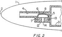
第2図は開閉状態にある本発明の弁を有する第1図の筆記具の部分的断面図、
第3図は閉鎖状態にある本発明の弁の第2実施例を含む筆記具の一方の側面から見た部分的断面図、
第4図は第3図の筆記具の上から見た部分的断面図、
第5図は開閉状態にある弁を含む第3図の筆記具の一方の側面から見た部分的断面図、
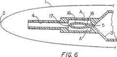
第6図は第5図の筆記具の上から見た部分的断面図、
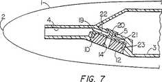
第7図は閉鎖状態にある本発明の弁の第3実施例を含む筆記具の部分的断面図、
第8図は開放状態にある弁を含む第7図の筆記具の部分的断面図、
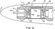
第9図は閉鎖位置にある本発明弁の第4実施例を含む筆記具の一方の側面から見た部分的断面図、
第10図は第9図の筆記具の上から見た部分的断面図、
第11図は開放状態にある弁を有する第9図および第10図の筆記具の上から見た部分的断面図、また
第12図は筆記具中に挿入する前の弁の一方の側面から見た部分的断面図である。
下記の説明全体を通して、相互に対応する各実施例の特徴は同一参照数字を有する。
第1図と第2図には、筆記先端2を有する筆記具1の筆記端部を示す。筆記具1はインクを収容するタンク3を有し、このタンクは通常大気圧であるが大気圧以上の圧力とする事ができる。インク送りチャンバ4がインクをタンク3から筆記具先端2に誘導し、インクはタンクの小開口5を通してインク送りチャンバ4まで連通する。インク送りチャンバ4は中空毛管とし、またはキャピラリー溝穴とし、または繊維質/多孔性材料を含みまたはこの種の材料から成り、この材料がインクによって飽和されてこのインクが筆記中に抽出される。
弁6は一般にカップ状を成し、円形断面を有し、その底部7は頂部8より大直径を有し、また頂部8と底部7との間に段部9が配置される。弁6はシリコーンゴムなどの弾性可撓性材料から成る。弁6は筆記具1の凹部10の中に着座し、弁6の段部9が凹部10の段部11に対してリテーナ12によって保持されている。リテーナ12は凹部10の中に押しばめされて弁6を定位置に保持する。環状リッジ(図示されていない)が凹部10の中に備えられて、リテーナ12の環状グルーブの中に「嵌合」するようにする事ができる。あるいは、または追加的に、リテーナ12を接着剤などの任意適当手段によって凹部10の中に固着する事ができる。
リテーナ12は段部13を有し、この段部13上に弁底部7の下側面が着座して、リテーナ12の一部が弁6の中空内部に入って弁6を凹部10の中に正確に確実に保持する。リテーナ12は中心通し孔14を有し、この孔14はその一方の側面において大気に開き、他方の側面において弁6の内部に開く。従ってリテーナ12の通し孔14は、大気圧が弁6の内部に加えられる事を意味する。
弁6の頂部8がインク送りチャンバ4の中に突出して、常態ではその側壁がタンク3中の開口5を密封し、インクがタンク3からインク送りチャンバ4に流れないようにする。弁6の頂部8はインク送りチャンバ4の中に突出しているので、弁6はその外側面においてインク送りチャンバ4中の大気圧を受ける。
筆記のために筆記具を使用する場合、インクがインク送りチャンバ4から流出して紙またはその他の媒体上に落ちる。これは、インク送りチャンバ4中の圧力を大気圧に対して相対的に低下させる。弁6の内側が大気圧を受けているのであるから、弁6の内側方向に作用する正味力が存在する。差圧が十分になると、頂部8の相対的に大きな頂面を第2図に図示のように外側に湾曲させ、これにより頂部8の相対的に短い側面が内側に湾曲させられる。側面が内側に湾曲されるに従って、タンク中の開口5が密封解除され、タンク3をインク送りチャンバ4と流体連通させる。従ってインクがタンク3から流出してインク送りチャンバ4を満たし、インクはインク送りチャンバ4から必要に応じて筆記先端2に進む。
筆記が停止されると、インク送りチャンバ4がインクで満たされ、インク送りチャンバ4中の圧力が再び上昇する。これにより、弁6の頂面が平坦になり、従って側壁面を外側に押しタンク3中の開口5を密封する。従ってインクは再びタンク3からインク送りチャンバ4に流れる事を防止される。例えば筆記速度とインク送りチャンバ4から抽出されるインク量に伴なうインク送りチャンバ4中の圧力変動とに従って、弁6が筆記の進行に従って開位置と閉位置との間を揺動する事を注意しなければならない。
第3図乃至第6図は弁15の第2実施例を成す筆記具1の筆記端部を示す。弁15の第2実施例は第1図および第2図の弁6の第1実施例と類似である。しかしこの実施例においては、弁15は比較的短い短軸と比較的長い長軸とを有する長円形断面であるので、弁15は一般に高い狭い形状を有する。従って弁15は2つの大きな平坦な対向側面16と2つの狭い対向側面17とを有する。開口5の狭い側面17上に突起18が配置され、この突起18は常態においてタンク3の開口5を密封するサイズおよび形状を有する。
弁15の狭い高い形状の故に、筆記中に、インク送りチャンバ4中の圧力がリテーナ12の通し孔14を通して弁15の内部に加えられる大気圧に対して低下する時、第4図と第6図とを比較すれば明らかなように、弁15の頂部8の大きな平坦側面16が外側に湾曲する。これは第3図と第5図とを比較すれば明らかなように、細い側壁17を内側に引張り、従って突起18をタンク3の開口5から引き離し、タンク3とインク送りチャンバ4との間の流体連通を開く。従ってインクがインク送りチャンバ4中の流路Aにそって弁15の回りに流れてインクを満たし、次にこのインクがインク送りチャンバ4から抽出される。筆記が停止しインク送りチャンバ4中の圧力が十分に上昇すると、大きな側壁16が内側に相互の方に緩み、狭い側壁17を押して開口5を密封する。
第7図と第8図に第3型の弁19を示す。弁19は全体としてカップ状を成し、リテーナ12によって筆記具1の凹部10の中に保持されている。タンク3中の開口5が弁の側壁または側壁上の突起によって密封される前記の弁の2実施例と相違し、第3実施例の弁19は、弁体23の頂面22の一部を成す弁棒21上に弁ヘッド20を有する。弁ヘッド20はタンク3の内側面に着座し常態で開口5を密封している。弁棒21は開口5の中に入り、この弁棒と開口5の縁との間に弁棒の外周にギャップを残すのに十分な程度に細い。
弁19の外側頂面22は開口5を有するタンク3の端壁から離間されているので、その一方の側において(弁ヘッド30の側において)インク送りチャンバ4中の圧力を受ける。頂面22の他方の内側面は、リテーナ12の通し孔14を通して大気圧を受ける。
インクが筆記先端2から抽出されインク送りチャンバ4中の圧力が低下するに従って、弁19の頂面22の内側に作用する大気圧が相対的に大きくなって、頂面22を第8図に図示のように外側に湾曲させる。この外側湾曲により弁ヘッド20が持ち上げられ、開口5を開く。従ってインクがタンク3から開口5を通して(弁棒21の回りを通って)インク送りチャンバ4に流れ、次に筆記先端2に達する。筆記が停止された時、インク送りチャンバ4中の圧力が上昇して、外側面22を再び平坦にし、従って弁ヘッド20を引張ってタンク内側面に当接させ、開口5を閉じる。
この実施例においては、タンク3中のインク圧が弁19を閉鎖する傾向を有する。これは、タンク中のインク圧が弁ヘッド20を押して、タンク3の開口5と密封係合させるからである。従ってもし例えば筆記具が落下し、または筆記具が例えば航空機の中で高空に達しまたは使用中に筆記具が暖められる事によりタンク3中の圧力が周囲大気圧より上昇させられた場合、弁19がさらに強く密封する傾向を示し、良好な密封状態を保証する。
第9図乃至第12図に図示の本発明の好ましい実施態様によれば、筆記先端2を有する筆記具1は図示のような平衡弁カートリッジ30を有する。弁カートリッジ30は、一般に大気圧にあるインクを収容するためのタンク3と、インクをタンク3から筆記先端2に誘導するインク送りチャンバ4とを形成する壁体構造から成る。この壁体構造はさらに弁チャンバ31を備え、この弁チャンバ31はタンク3に開く第1開口32と、弁チャンバ31とインク送りチャンバ4とを連通する第2開口34とを有する。
第12図に最もよく図示されているように、弁36が弁チャンバ32の中に配置され、この弁36は第3図乃至第6図の弁構造と同様に短い短軸と比較的長い長軸とを有する実質的に長円形断面を有する。しかしこの弁実施態様においては、弁36はその本体から下方外側に延在する一対の弾性アーム38、40を備える。弁36は前述のように弾性可撓性材料から成り、底部において大気圧に開いたカップ状を成し、その底壁42がカップ部分から外側に延在し、弁チャンバ31の底面と密封係合する。弁36の底壁42は弁チャンバ31の開口に対して接着剤などの任意適当な手段によって密着する事ができ、その唯一の要件はこのシールが使用中に弁36の受ける差圧に耐える型のものである事である。第12図について述べれば、弁カートリッジを筆記具1の中に組立てる前に、弾性アーム38が弁36の本体から外側に弾発されて第1開口32と密封係合しているが、弾性アーム40は外側に弾発されて第2開口34と密封係合している。
第9図、第10図および第11図に図示のように、弁カートリッジ30が筆記具1の中に組立てられる時、筆記具の中に第2開口34と整列するように取付けられたアーム移動部品44が開口34を通して延在し、弾性アーム40と接触してこのアームを開口34から移動させて、カートリッジ30の使用中にこの開口34を開放状態に保持する。アーム移動部品44は、単一のインクチャンネルキャピラリー溝穴として筆記具の操作中にインクがこのアーム移動部品44を通して流出する事ができるようにし、または多孔性のフィードスティックとし、または通常の穿孔管機構とする事ができる。従って、弁カートリッジ30を筆記具1の中に配置する前には、アーム40が開口34を通るインク流に対して確実なシールを成す事ができるが、カートリッジの設置および筆記具の使用中には、弾性アーム40が部品44によって移動させられて開放位置に保持される事が理解されよう。
操作に際して、弁36は前記の実施例と同様に機能する。筆記具が使用される時、インクがインク送りチャンバ4から紙またはその他の媒体上に流出し、インク送りチャンバ4中の圧力を大気圧に対して低下させる。この場合、弁36の内部が大気圧に保持されているので、弁内側面に作用する正味力が存在し、この差圧が十分になると、この正味力が第11図に図示のように弁の薄い側壁を外側に膨張させる。側壁が外側に膨張すると、弁の比較的狭い端壁が内側に移動して弾性アーム38を内側に移動させ、アーム38を開口32から移動させてインクをタンク3から弁チャンバ31の中に流入させ、次にインク送りチャンバ4の中に流出させる。このようにしてインクが絶えずタンク3から抽出されてインク送りチャンバ4を充填し、このインク送りチャンバ4からインクが必要に応じて筆記先端2まで通過する。
前記の各弁は筆記具の交換自在の充填ユニットの中に使用し、または筆記具の中に一体的に備える事ができる。The present invention relates to a writing instrument, and more particularly to an ink container for a writing instrument, and more particularly to a valve used in this type of container.
There are various mechanisms for preventing or controlling ink spillage from the writing instrument, particularly when the writing instrument is not in use. For example, in a fountain pen, ink is extracted by capillary action during writing, but in other cases, ink generally does not flow to the tip of the writing, and the ink flow is a small aperture in an ink tank called “wear”. The air enters through the wear instead of the ink that is controlled by Such pens often include a “collector” that acts as a buffer for storing ink when, for example, ink is pushed out of the tank due to expansion of air in the ink tank.
It is an object of the present invention to provide an improved ink flow control system.
According to the present invention, in an ink container for a writing instrument, the container is
A tank for containing ink;
An ink feeding means connected to the writing tip for sending ink from the tank to the writing tip;
Valve means disposed between the tank and the ink feed means for controlling ink flow to the ink feed means, the valve means on one side for adjusting the pressure in the ink feed means. Receiving the atmospheric pressure on the other side, and when the pressure in the ink feeding means drops sufficiently below the atmospheric pressure acting on the valve, the valve means opens and ink flows out from the tank to the ink feeding means An ink container for a writing instrument is provided.
This valve provides a positive closure during non-writing periods. In addition, this valve provides reliable control of ink flow during writing. This valve occupies a smaller volume than, for example, a normal fountain pen or writing instrument collector. The valve can also be used for other types of writing instruments such as fiber tip pens and ballpoint pens. This valve can be arranged so that the ink in the tank closes the valve. This ensures that the ink does not reach the writing tip if the writing instrument falls by accident. This valve can be used with a follower, which can be a plug placed on the ink surface to follow the ink descending in the tank as the ink is extracted during writing.
The valve can be an elastic member that deforms under pressure and forms a passage through which ink passes through the ink feed means. Alternatively or additionally, the valve or part thereof can translate upon opening.
The valve includes a valve body and a valve head, and the valve head is disposed so as to seal an ink flow path between the ink tank and the ink feeding means in a normal state, and the valve head is disposed inside the tank. The valve body is disposed outside the tank, and is disposed such that one side surface thereof is exposed to atmospheric pressure and the other side surface is exposed to the ink feeding unit. An internal pressure drop raises the valve head and opens an ink flow path between the tank and the ink feed means.
The container can be a replaceable filling unit. Alternatively, the container can be deployed in a writing instrument.
When the container is used as a replaceable unit, it can include a first opening communicating with the tank and a second opening that opens into the ink feed means. The valve also includes a first arm for closing the first opening and a second arm for closing the second opening. The first arm is moved to open the first opening by the differential pressure acting on the valve, and the second arm is held in the open position by an external part arranged on the writing instrument.
Hereinafter, the present invention will be described in detail with reference to embodiments shown in the drawings, but the present invention is not limited thereto.
FIG. 1 is a partial sectional view of a writing instrument including a first embodiment of the valve of the present invention in a closed state;
FIG. 2 is a partial cross-sectional view of the writing instrument of FIG. 1 having the valve of the present invention in an open / closed state,
FIG. 3 is a partial cross-sectional view seen from one side of a writing instrument including a second embodiment of the valve of the present invention in a closed state;
FIG. 4 is a partial cross-sectional view as seen from above the writing instrument of FIG.
FIG. 5 is a partial sectional view seen from one side of the writing instrument of FIG.
FIG. 6 is a partial cross-sectional view as seen from above the writing instrument of FIG.
FIG. 7 is a partial sectional view of a writing instrument including a third embodiment of the valve of the present invention in a closed state;
FIG. 8 is a partial cross-sectional view of the writing instrument of FIG. 7 including the valve in an open state;
FIG. 9 is a partial sectional view seen from one side of a writing instrument including a fourth embodiment of the valve of the present invention in the closed position;
FIG. 10 is a partial sectional view as seen from above the writing instrument of FIG.
FIG. 11 is a partial cross-sectional view from above of the writing instrument of FIGS. 9 and 10 with the valve in an open state, and FIG. 12 is viewed from one side of the valve prior to insertion into the writing instrument. FIG.
Throughout the following description, features of each embodiment that correspond to each other have the same reference numerals.
1 and 2 show a writing end portion of a writing instrument 1 having a writing tip 2. The writing instrument 1 has a
The valve 6 is generally cup-shaped, has a circular cross section, its bottom 7 has a larger diameter than the top 8, and a
The
The top 8 of the valve 6 protrudes into the
When using a writing instrument for writing, ink flows out of the
When writing is stopped, the
3 to 6 show the writing end portion of the writing instrument 1 constituting the second embodiment of the valve 15. The second embodiment of the valve 15 is similar to the first embodiment of the valve 6 of FIGS. However, in this embodiment, the valve 15 has an oval cross-section with a relatively short minor axis and a relatively long major axis, so that the valve 15 generally has a high narrow shape. The valve 15 thus has two large flat opposing
4 and 6 when the pressure in the
A
Since the outer
As the ink is extracted from the writing tip 2 and the pressure in the
In this embodiment, the ink pressure in the
According to the preferred embodiment of the present invention shown in FIGS. 9-12, the writing instrument 1 having a writing tip 2 has a
As best illustrated in FIG. 12, a
As shown in FIGS. 9, 10 and 11, when the
In operation, the
Each of the valves can be used in a replaceable filling unit of the writing instrument or can be provided integrally in the writing instrument.
Claims (10)
Translated fromJapanese前記インク送り手段へのインク流を制御するために前記タンクと前記インク送り手段との間に配置された弁手段を含み、前記弁手段は、一方の側において前記インク送り手段中の圧力を受け、他方の側において大気圧を受け、前記インク送り手段中の圧力が前記弁に作用する大気圧以下に十分に落ちた時に前記弁手段が開いてインクを前記タンクから前記インク送り手段に流出させる事を特徴とする筆記具用インク容器。In an ink container for a writing instrument, comprising: a tank for storing ink; and an ink feeding means for transporting ink from the tank.
Valve means disposed between the tank and the ink feed means for controlling the ink flow to the ink feed means, the valve means receiving pressure in the ink feed means on one side; When the pressure on the other side receives atmospheric pressure and the pressure in the ink feeding means sufficiently falls below the atmospheric pressure acting on the valve, the valve means opens and causes ink to flow out from the tank to the ink feeding means. An ink container for writing instruments.
Applications Claiming Priority (3)
| Application Number | Priority Date | Filing Date | Title |
|---|---|---|---|
| GB9325891.1 | 1993-12-17 | ||
| GB939325891AGB9325891D0 (en) | 1993-12-17 | 1993-12-17 | Writing instruments |
| PCT/GB1994/002696WO1995016577A1 (en) | 1993-12-17 | 1994-12-09 | Improvements in or relating to writing instruments |
Publications (2)
| Publication Number | Publication Date |
|---|---|
| JPH09506562A JPH09506562A (en) | 1997-06-30 |
| JP3664407B2true JP3664407B2 (en) | 2005-06-29 |
Family
ID=10746819
Family Applications (1)
| Application Number | Title | Priority Date | Filing Date |
|---|---|---|---|
| JP51659395AExpired - Fee RelatedJP3664407B2 (en) | 1993-12-17 | 1994-12-09 | Ink containers for writing instruments |
Country Status (20)
| Country | Link |
|---|---|
| US (1) | US5735624A (en) |
| EP (1) | EP0734328B1 (en) |
| JP (1) | JP3664407B2 (en) |
| CN (1) | CN1051283C (en) |
| AU (1) | AU689833B2 (en) |
| BR (1) | BR9408350A (en) |
| CA (1) | CA2179277C (en) |
| DE (1) | DE69413252T2 (en) |
| EG (1) | EG20444A (en) |
| ES (1) | ES2120715T3 (en) |
| GB (1) | GB9325891D0 (en) |
| IL (1) | IL111812A (en) |
| MY (1) | MY131720A (en) |
| NZ (1) | NZ277070A (en) |
| PL (1) | PL315034A1 (en) |
| RU (1) | RU2123940C1 (en) |
| TW (1) | TW262437B (en) |
| UY (1) | UY23875A1 (en) |
| WO (1) | WO1995016577A1 (en) |
| ZA (1) | ZA949490B (en) |
Families Citing this family (10)
| Publication number | Priority date | Publication date | Assignee | Title |
|---|---|---|---|---|
| US5906446A (en)* | 1996-10-22 | 1999-05-25 | Bic Corporation | Fillerless writing instrument |
| DE19706967C1 (en)* | 1997-02-21 | 1998-09-03 | Kaufmann R Dataprint | Liquid regulator for supplying a consumer with liquid from a liquid supply |
| GB9709513D0 (en) | 1997-05-09 | 1997-07-02 | Parker Pen Products | Marking instrument |
| US6004418A (en)* | 1997-10-28 | 1999-12-21 | Lear Corporation | Method of joining a cover material to a substrate utilizing electrically conductive bonding |
| DE29819071U1 (en)* | 1998-10-20 | 2000-03-02 | Anderka, Gerold, 25474 Ellerbek | Handwriting or application device |
| GB2359786A (en) | 2000-03-02 | 2001-09-05 | Gillette Co | Ink cartridge with plug and valve |
| US6916088B2 (en)* | 2001-04-20 | 2005-07-12 | Hewlett-Packard Development Company, L.P. | Ink container configured to establish reliable fluidic connection to a receiving station |
| JP4461728B2 (en)* | 2003-07-29 | 2010-05-12 | ブラザー工業株式会社 | Inkjet recording apparatus and ink supply apparatus |
| JP7339823B2 (en)* | 2019-09-17 | 2023-09-06 | 三菱鉛筆株式会社 | Applicator |
| JP7441655B2 (en) | 2020-01-22 | 2024-03-01 | 三菱鉛筆株式会社 | applicator |
Family Cites Families (10)
| Publication number | Priority date | Publication date | Assignee | Title |
|---|---|---|---|---|
| US3877619A (en)* | 1974-05-15 | 1975-04-15 | Jr Evelio F Chavez | Pneumatic self-closing valve for a tube of flowable material |
| US4364684A (en)* | 1979-06-21 | 1982-12-21 | Pentel Kabushiki Kaisha | Writing instrument |
| FR2538762A1 (en)* | 1982-12-30 | 1984-07-06 | Dupont S T | IMPROVEMENTS TO CARTRIDGE-RECHARGE STYLOGRAPHS |
| JPS6145191U (en)* | 1984-08-29 | 1986-03-25 | パイロツトインキ株式会社 | writing implements |
| US4588319A (en)* | 1984-10-25 | 1986-05-13 | Nicolet Instrument Corporation | Marking instrument |
| FR2580234B1 (en)* | 1985-04-17 | 1989-07-07 | Mitsubishi Pencil Co | INSTRUMENT FOR WRITING, PAINTING OR THE LIKE |
| DE3772608D1 (en)* | 1986-04-10 | 1991-10-10 | Jiro Hori | DEVICE, FOR EXAMPLE, PEN, FOR APPLYING LIQUID. |
| EP0413273A1 (en)* | 1989-08-14 | 1991-02-20 | Jiro Hori | Valve for a writing instrument |
| DE4013510C2 (en)* | 1990-04-27 | 1995-04-20 | Rotring Int Gmbh | Tube pen tip, especially for use in drawing plotters |
| DE4135605A1 (en)* | 1991-10-29 | 1993-05-06 | Rotring-Werke Riepe Kg, 2000 Hamburg, De | WRITING OR DRAWING DEVICE |
- 1993
- 1993-12-17GBGB939325891Apatent/GB9325891D0/enactivePending
- 1994
- 1994-01-20TWTW083100469Apatent/TW262437B/zhactive
- 1994-11-29ZAZA949490Apatent/ZA949490B/enunknown
- 1994-11-29ILIL111812Apatent/IL111812A/enactiveIP Right Grant
- 1994-12-09EPEP95902872Apatent/EP0734328B1/ennot_activeExpired - Lifetime
- 1994-12-09WOPCT/GB1994/002696patent/WO1995016577A1/enactiveIP Right Grant
- 1994-12-09ESES95902872Tpatent/ES2120715T3/ennot_activeExpired - Lifetime
- 1994-12-09DEDE69413252Tpatent/DE69413252T2/ennot_activeExpired - Fee Related
- 1994-12-09USUS08/663,242patent/US5735624A/ennot_activeExpired - Lifetime
- 1994-12-09AUAU11962/95Apatent/AU689833B2/ennot_activeCeased
- 1994-12-09CNCN94194510Apatent/CN1051283C/ennot_activeExpired - Fee Related
- 1994-12-09JPJP51659395Apatent/JP3664407B2/ennot_activeExpired - Fee Related
- 1994-12-09BRBR9408350Apatent/BR9408350A/ennot_activeApplication Discontinuation
- 1994-12-09NZNZ277070Apatent/NZ277070A/enunknown
- 1994-12-09PLPL94315034Apatent/PL315034A1/enunknown
- 1994-12-09RURU96115188Apatent/RU2123940C1/enactive
- 1994-12-09CACA002179277Apatent/CA2179277C/ennot_activeExpired - Fee Related
- 1994-12-12MYMYPI94003313Apatent/MY131720A/enunknown
- 1994-12-13EGEG78294Apatent/EG20444A/enactive
- 1994-12-19UYUY23875Apatent/UY23875A1/ennot_activeIP Right Cessation
Also Published As
| Publication number | Publication date |
|---|---|
| GB9325891D0 (en) | 1994-02-23 |
| EP0734328B1 (en) | 1998-09-09 |
| RU2123940C1 (en) | 1998-12-27 |
| ES2120715T3 (en) | 1998-11-01 |
| CA2179277A1 (en) | 1995-06-22 |
| CA2179277C (en) | 2000-02-08 |
| BR9408350A (en) | 1997-08-26 |
| JPH09506562A (en) | 1997-06-30 |
| DE69413252D1 (en) | 1998-10-15 |
| NZ277070A (en) | 1998-06-26 |
| US5735624A (en) | 1998-04-07 |
| UY23875A1 (en) | 1995-06-13 |
| TW262437B (en) | 1995-11-11 |
| PL315034A1 (en) | 1996-09-30 |
| CN1051283C (en) | 2000-04-12 |
| DE69413252T2 (en) | 1999-04-15 |
| AU1196295A (en) | 1995-07-03 |
| ZA949490B (en) | 1995-08-14 |
| EP0734328A1 (en) | 1996-10-02 |
| AU689833B2 (en) | 1998-04-09 |
| IL111812A (en) | 1998-06-15 |
| IL111812A0 (en) | 1995-01-24 |
| EG20444A (en) | 1999-04-29 |
| WO1995016577A1 (en) | 1995-06-22 |
| MY131720A (en) | 2007-08-30 |
| CN1137773A (en) | 1996-12-11 |
Similar Documents
| Publication | Publication Date | Title |
|---|---|---|
| US6000788A (en) | Ink cartridge for ink jet printer | |
| US7475972B2 (en) | One-way valve, valve unit assembly, and ink cartridge using the same | |
| US6053604A (en) | Ink refilling method and apparatus for ink cartridge | |
| JP3664407B2 (en) | Ink containers for writing instruments | |
| EP0624483A1 (en) | Writing instrument | |
| US6186620B1 (en) | Ink pressure control apparatus for ink-jet pens | |
| US4569612A (en) | Liquid applicator and valve therefor | |
| US5222824A (en) | Regulated ink flow control system for pen | |
| RU96115188A (en) | WRITER INK CONTAINER | |
| US6863460B2 (en) | Reservoir pens and ink cartridges therefor | |
| US6309127B1 (en) | Caps for writing instruments | |
| JP3179589B2 (en) | Writing implement | |
| JP3924933B2 (en) | Writing instrument | |
| JP4482180B2 (en) | Applicator | |
| JPH0692082A (en) | Writing tool | |
| HK1019007B (en) | Ink cartridge for ink jet printer | |
| HK1028972B (en) | Ink cartridge for ink jet printer |
Legal Events
| Date | Code | Title | Description |
|---|---|---|---|
| A01 | Written decision to grant a patent or to grant a registration (utility model) | Free format text:JAPANESE INTERMEDIATE CODE: A01 Effective date:20050111 | |
| RD02 | Notification of acceptance of power of attorney | Free format text:JAPANESE INTERMEDIATE CODE: A7422 Effective date:20041228 | |
| RD04 | Notification of resignation of power of attorney | Free format text:JAPANESE INTERMEDIATE CODE: A7424 Effective date:20041227 | |
| A61 | First payment of annual fees (during grant procedure) | Free format text:JAPANESE INTERMEDIATE CODE: A61 Effective date:20050208 | |
| A01 | Written decision to grant a patent or to grant a registration (utility model) | Free format text:JAPANESE INTERMEDIATE CODE: A01 Effective date:20050308 | |
| TRDD | Decision of grant or rejection written | ||
| A61 | First payment of annual fees (during grant procedure) | Free format text:JAPANESE INTERMEDIATE CODE: A61 Effective date:20050325 | |
| R150 | Certificate of patent or registration of utility model | Free format text:JAPANESE INTERMEDIATE CODE: R150 | |
| FPAY | Renewal fee payment (event date is renewal date of database) | Free format text:PAYMENT UNTIL: 20090408 Year of fee payment:4 | |
| FPAY | Renewal fee payment (event date is renewal date of database) | Free format text:PAYMENT UNTIL: 20100408 Year of fee payment:5 | |
| FPAY | Renewal fee payment (event date is renewal date of database) | Free format text:PAYMENT UNTIL: 20110408 Year of fee payment:6 | |
| FPAY | Renewal fee payment (event date is renewal date of database) | Free format text:PAYMENT UNTIL: 20120408 Year of fee payment:7 | |
| LAPS | Cancellation because of no payment of annual fees |